generative assembly structural analysis site map preface what's
TRANSCRIPT

Generative Assembly Structural Analysis
Site Map
Preface
What's New?
Getting Started
Basic Tasks
Workbench Description
Index
© Dassault Systèmes 1994-99. All rights reserved.

Site MapPreface
Using This GuideMore Information
What's newGetting Started
Entering Analysis Connections WorkbenchCreating Analysis Face Face ConnectionCreating Analysis Welding Point ConnectionCreating Property ConnectionsComputing the Static Case
Basic Tasks
Before You BeginAnalysis Connections
Creating Face Face ConnectionsCreating Distant ConnectionsCreating Welding Point Connections
Property Connections
Creating Fastened ConnectionsCreating Slider ConnectionsCreating Contact ConnectionsCreating Bold Tightening ConnectionsCreating Virtual Rigid Bold Tightening ConnectionsCreating Virtual Spring Bold Tightening ConnectionsCreating Pressure Fitting ConnectionsCreating Rigid ConnectionsCreating Smooth ConnectionsCreating Spot Welding Connections
Workbench Description
Property Connections ToolbarAnalysis Connection Toolbar
Index

PrefaceELFINI Structural Analysis, Generative Part Structural Analysis and GenerativeAssembly Structural Analysis Version 5 products allow you to rapidly perform first ordermechanical analysis for 3D parts systems.
As a scalable line of products, ELFINI Structural Analysis Version 5 along with GenerativePart Structural Analysis and Generative Assembly Structural Analysis can becooperatively used with other current or future companion products such as Part Design,Assembly Design and Generative Drafting. The widest application portfolio in the industry isalso accessible through interoperability with CATIA Solutions Version 4 to enable support of thefull product development process from initial concept to product in operation.
The Generative Part Structural Analysis application is intended for the casual user.Indeed, its intuitive interface offers the possibility to obtain mechanical behaviorinformation with very few interactions. The dialog boxes are self explanatory and requirepractically no methodology, all defining steps being commutative.
The Generative Assembly Structural Analysis product has been designed as anintegrated extension to Generative Part Structural Analysis enabling the study of themechanical behavior of a whole assembly. The product has been conceived with thesame "easy to learn" and "fun to use" ergonomics principles.

The ELFINI Structural Analysis product is a natural extensions of both abovementioned products, fully based on the V5 architecture. It represents the basis of allfuture mechanical analysis developments.

The ELFINI Structural Analysis User's Guide has been designed to show you how to analyzea system consisting of single parts or of assemblies of parts, operating within a specifiedenvironment. There are several ways for undergoing a part to external actions. There are alsoseveral types of useful output information. This book aims at illustrating these variouspossibilities.
Using This GuideMore Information

Using This GuideThis book is intended for the user who needs to quickly become familiar with AnalysisConnections Version 5. The user should be familiar with basic concepts such as documentwindows, standard and view toolbars.
To get the most out of this guide, we suggest you start reading and performing the step-by-steptutorial "Getting Started". This tutorial will show you how to analyze a part from scratch.
The "Basic Tasks" section presents the main capabilities of the product. Each individual task iscarefully defined and explained in detail.

Where to Find More InformationPrior to reading this book, we recommend that you read:
Generative Structural Analysis (GPS and EST) user's guideInfrastructure User's guide Version 5Part Design User's GuideConventions chapter

ConventionsCertain conventions are used in CATIA, ENOVIA & DELMIA documentation to help yourecognize and understand important concepts and specifications. The following textconventions may be used: The titles of CATIA documents appear in this manner throughout the text. File -> New identifies the commands to be used.
The use of the mouse differs according to the type of action you need to perform.
Use thismouse button, whenever you read
Select (menus, commands, geometry in graphics area, ...)Click (icons, dialog box buttons, tabs, selection of a location in the document window,...)Double-clickShift-clickCtrl-clickCheck (check boxes)DragDrag and drop (icons onto objects, objects onto objects)
DragMove
Right-click (to select contextual menu)
Graphic conventions are denoted as follows:
indicates the estimated time to accomplish a task.
indicates a target of a task.
indicates the prerequisites.
indicates the scenario of a task.
indicates tips

indicates a warning.
indicates information.
indicates the end of a task.
indicates functionalities that are new or enhanced with this Release.Enhancements can also be identified by a blue-colored background in the left-handmargin.

Getting StartedThis tutorial will guide you step-by-step through your first Generative Assembly StructuralAnalysis session, allowing you to get acquainted with the product. You just need to follow theinstructions as you progress.
In this tutorial, you will
1. create Analysis Connections (Analysis Connections workbench),
2. add properties to these connections (Generative Structural Analysis
workbench) and then compute the CATAnalysis document.
Entering Analysis Connections WorkbenchCreating Analysis Face Face Connection
Creating Analysis Welding Point ConnectionCreating Property Connections
Computing the Static Case
These tasks should take about 15 minutes to complete.

Entering Analysis ConnectionsWorkbench
The Analysis Connections workbench of the Generative Assembly Structural Analysisproduct let's you add constraints to existing geometry. You can also add these constraintsusing Product workbench (Design mode). If so, the geometry will be over-constrained.
Open the LandingGear.CATProduct document from the sample directory.

1. Select Start-> Analysis & Simulation -> Analysis Connections from the menu bar.
Now that you entered the Analysis Connections workbench ...
... the following commands are available:
In other words, you can create Face Face, Distant or Welding point connections.
In this tutorial, you will create Connections (Analysis Connections workbench of theGenerative Assembly Structural Analysis product), add property connections(Generative Structural Analysis workbench of the Generative Part Structural Analysisproduct) and then compute the CATAnalysis document.

Creating a Face Face ConnectionFace Face Analysis Connections are connections used for connecting either faces that areparallel to each others or concentric cylinders, on an assembly model.
Remember that you entered the Analysis Connections workbench of theGenerative Assembly Structural Analysis product.
This task shows you how to create a Face Face Connection.
1. Select the Face Face Connection icon.
The Analysis Face Face Connection dialog box is displayed. 2. Select a first face on the assembly.
To manipulate the product more easily click with the middle mouse button on the product.
The Analysis Face Face Connection dialog box displays the selected face.

3. Select a second face on the assembly.
The Analysis Face Face Connections dialog box displays the selected faces.
4. Click OK in the Face Face dialog box.
A symbol appears on each connected face.

The Analysis Connection Manager object appears in the specification tree.

Creating a Welding Point ConnectionWelding Point Analysis Connections are connections used for projecting welding pointsonto two faces, on an assembly model.
You are still in the Analysis Connections workbench of the Generative AssemblyStructural Analysis product
This task shows you how to create a Welding Point Connection.
1. Select Start -> Analysis & Simulation -> Analysis Connections.
2. Select the Welding Point Connection icon.
The Analysis Welding Points Connection dialog box is displayed. 3. Select a first face on the assembly.
The Analysis Welding Points Connection dialog box appears as shown here:

4. Select a second face on the assembly.
The Analysis Welding Points Connection dialog box appears as shown here:

5. Multi-select a set of points in a single Open Body, on the product.
OR
5. Select a set of points in a single Open Body, on the specification tree. In this case selectOpen_body.1.
The Analysis Welding Points Connection dialog box appears as shown here:

6. Click OK in the Analysis Welding Points Connection dialog box.
Symbols appear on the points connecting the faces.
Analysis Connection Manager appears in the specification tree.

Adding Property ConnectionsProperty Connections are used to specify the boundary interaction between bodies in anassembled system. Once the geometric assembly positioning constraints are defined atthe Product level, the user can specify the physical nature of the constraints.
You will now enter in the Generative Structural Analysis workbench of theGenerative Part Structural Analysis product. For this, Select Start-> Analysis &Simulation -> Generative Structural Analysis from the menu bar and select the StaticAnalysis case and click OK in the New Analysis Case dialog box.
1. Select the desired Property Connection icon.
Connections
Advanced Connections
2. Select the previously created Analysis connections (either from the specification tree oron the geometry).
Selecting the Spot Welding icon and theWelding Point connection:
You create this Spot Welding Propertyconnection:

The Spot Welding Connection objectappears in the specification tree.
Repeat the same operation to create fastened Property connections on the Face-Faceconnection previously created.

Computing the Static CaseThe Compute command is most often applied to Analysis Case Solutions (which are particulartypes of objects sets). In this case, it generates the analysis case solution, along with partialresults for all objects involved in the definition of the Analysis Case.
The primary Static Solution Computation result consists of a displacement vector whosecomponents represent the values of the system degree of freedom. This result can be furtherprocessed to produce other results such as stresses, reaction forces, etc.
The program can compute simultaneously several Solution objects sets, with optimal parallelcomputation whenever applicable.
You are still in the Generative Structural Analysis workbench of the GenerativePart Structural Analysis product.
This task will show you how to compute the Static Case Solution of a Finite Element Model onwhich you previously created connections.
1. Click the Storage Location icon .
The Current Storage Location dialog box is displayed.
2. If needed, change the path of the Storage Result and/or Computation Data directory (ResultsData and Computation Data fields) to another directory.
The Results and Computation Data are stored in one single file with given extensions:
xxx.CATAnalysisResultsxxx.CATAnalysisComputations

3. Click the Compute icon .
The Compute dialog box appears.The Elfini Storage Location dialog box disappears.
4. Select the All default value proposed for defining which are the objects sets to be updated.
5. Click OK in the Compute dialog box to launch the computation.
At the bottom right of the screen, a series of status messages (Meshing, Factorization, Solution)informs you of the degree of advancement of the computation process.

Basic TasksThe basic tasks you will perform in the Generative Assembly Structural Analysis workbenchare:
Before You BeginAnalysis ConnectionsProperty Connections

Before You Begin
Before you begin you should be familiar with the following basic concepts on:Analysis strategyAnalysis Connections workbench
A Standalone Analysis Connection Workbench
When you create a connection, you generally first create an assembly constraint in the Assembly Design workbench.Then, in the Generative Structural Analysis workbench, you add a property on this constraint (fastened, pressurefitting, bolt and so forth). This property generates a Mesh part. The property is propagated to the above mentionedMesh part.
Why you will use Analysis Connections workbench:
In some cases, Assembly Design constraints are not sufficient to modelize connections from an Analysis viewpoint:
In order to support properties, users often need to define too many constraints using the Assembly Designworkbench, leading to over-constrained models that cannot be updated.
1.
It is impossible to define constraints that are not positioning constraints but connection constraints (for example :connecting one face from one solid with one face from another solid, these faces being not necessarilycoincident).
2.
In the case of surface parts assemblies, it is not possible to define positioning constraints.3.
It is impossible to modelize welding spot connections.4.
In order to meet these different needs, a new workbench called Analysis Connection was added to the GenerativeAssembly Design product. Analysis Connection let you create all these Connections dedicated to Analysis modeling.

About Analysis Connections Workbench
The Analysis Connections workbench allows you creating constraints that are not design constraints.
The Analysis Connections workbench let's you create face face, distance or welding constraints (called connections).As a user, you may need to add design face-to-face connections in order to create property constraints afterwards(Generative Structural Analysis workbench). As a result, a given number of these design constraints need to bede-activated so that the model is not over-constrained. You may also need to add design constraints at a given distance(this constraint goes through a virtual point) so that you can simulate a part that was not designed.
What Type of Property For What Type of Connection ?1. For Connections Between Two Surfaces
Connection Property Assembly Design Analysis Connection
Coincidence Contact Offset Face Face Distant Welding
Fastened
Slider
Contact
Rigid
Smooth
Spot welding

2. For Connections Between Two Parts
Connection PropertyAssembly Design Analysis Connection
Coincidence Contact Offset FaceFace Distant Welding
Fastened ( )
Slider ( )
Contact ( )
Rigid
Smooth
Bolt tightening
Pressure fitting
Virtual bolt tightening
Virtual spring bolttightening
Spot welding
3. For Connections Between a Part and a Surface

Connection Property Assembly Design Analysis Connection
Coincidence Contact Offset Face Face Distant Welding
Fastened
Slider
Contact
Rigid
Smooth
Spot welding
Analysis Connections
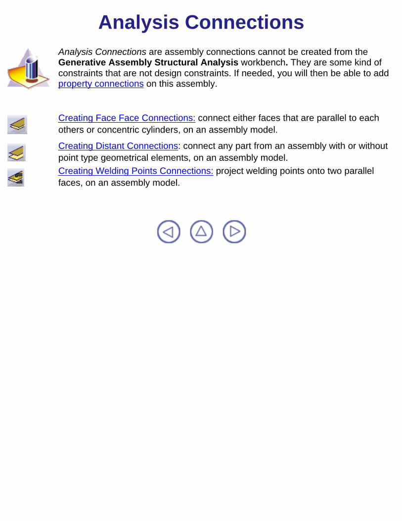
Analysis Connections are assembly connections cannot be created from theGenerative Assembly Structural Analysis workbench. They are some kind ofconstraints that are not design constraints. If needed, you will then be able to addproperty connections on this assembly.
Creating Face Face Connections: connect either faces that are parallel to eachothers or concentric cylinders, on an assembly model.
Creating Distant Connections: connect any part from an assembly with or withoutpoint type geometrical elements, on an assembly model. Creating Welding Points Connections: project welding points onto two parallelfaces, on an assembly model.

Creating a Face Face Connection
Face Face Analysis connections are connections used for connecting either facesthat are parallel to each others or concentric cylinders, on an assembly model.
This task shows you how to create a Face Face Connection.
Open the Sample18.CATAnalysis document.
Make sure that you entered the Analysis Connections workbench of the GenerativeAssembly Structural Analysis product.
1. Select the Face Face Connection icon.
The Analysis Face Face Connections dialog box is displayed.
2. Select a first face on the assembly.

3. Select a second face on the assembly.
The Analysis Face Face Connection dialog box appears as shown here:
4. Click OK in the Analysis Face Face Connections dialog box.
A symbol appears on each connected face.Analysis Connection Manager appears in the specification tree.
Creating a Distant Connection
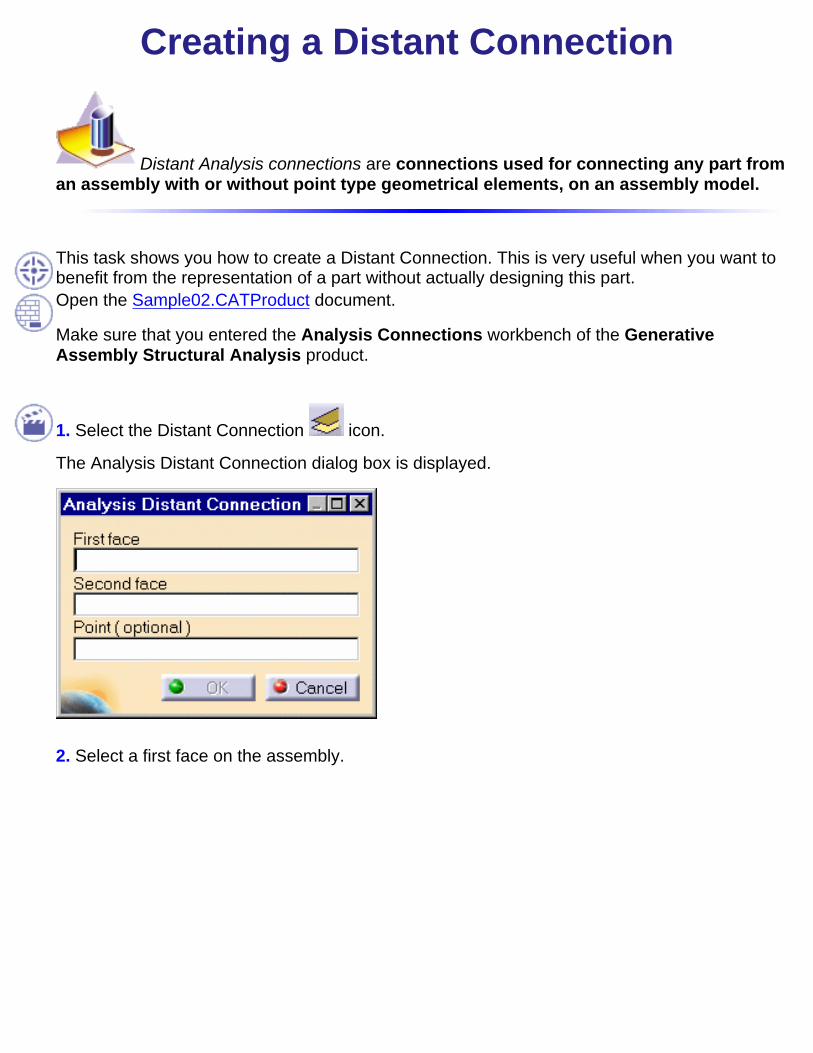
Distant Analysis connections are connections used for connecting any part froman assembly with or without point type geometrical elements, on an assembly model.
This task shows you how to create a Distant Connection. This is very useful when you want tobenefit from the representation of a part without actually designing this part.Open the Sample02.CATProduct document.
Make sure that you entered the Analysis Connections workbench of the GenerativeAssembly Structural Analysis product.
1. Select the Distant Connection icon.
The Analysis Distant Connection dialog box is displayed.
2. Select a first face on the assembly.

The Analysis Distant Connection dialog box appears as shown here.
3. Select a second face on the assembly.

4. Click OK in the Analysis Distant Connection dialog box.
A virtual point is automatically created and the distance connection will go through this virtualpoint.
OR
4. If needed, select a point and then click OK in the Analysis Distant Connection dialog box.
The Distant Analysis Connection.1 object now appears in the specification tree.

A symbol appears on each connected face.Analysis Connection Manager appears in the specification tree.

Creating a Welding Point Connection
Welding Point Analysis connections are connections used for projecting weldingpoints onto parallel faces, on an assembly model.
This task shows you how to create a Welding Point Connection.
Open the Sample03.CATProduct document: you created a set of 3D points on the assembly(Open Body).
Make sure that you entered the Analysis Connections workbench of the GenerativeAssembly Structural Analysis product.
1. Select the Welding Point Connection icon.
The Analysis Welding Points Connection dialog box is displayed.

2. Select a first face on the assembly.
The Analysis Welding Points Connection dialog box is updated:
3. Select a second face on the assembly.

The Analysis Welding Points Connection dialog box is updated:
4. Multi-select a set of points in a single Open Body.

The Analysis Welding Points Connection dialog box is updated:
5. Click OK in the Analysis Welding Points Connection dialog box.
Symbols appear on each connected face.
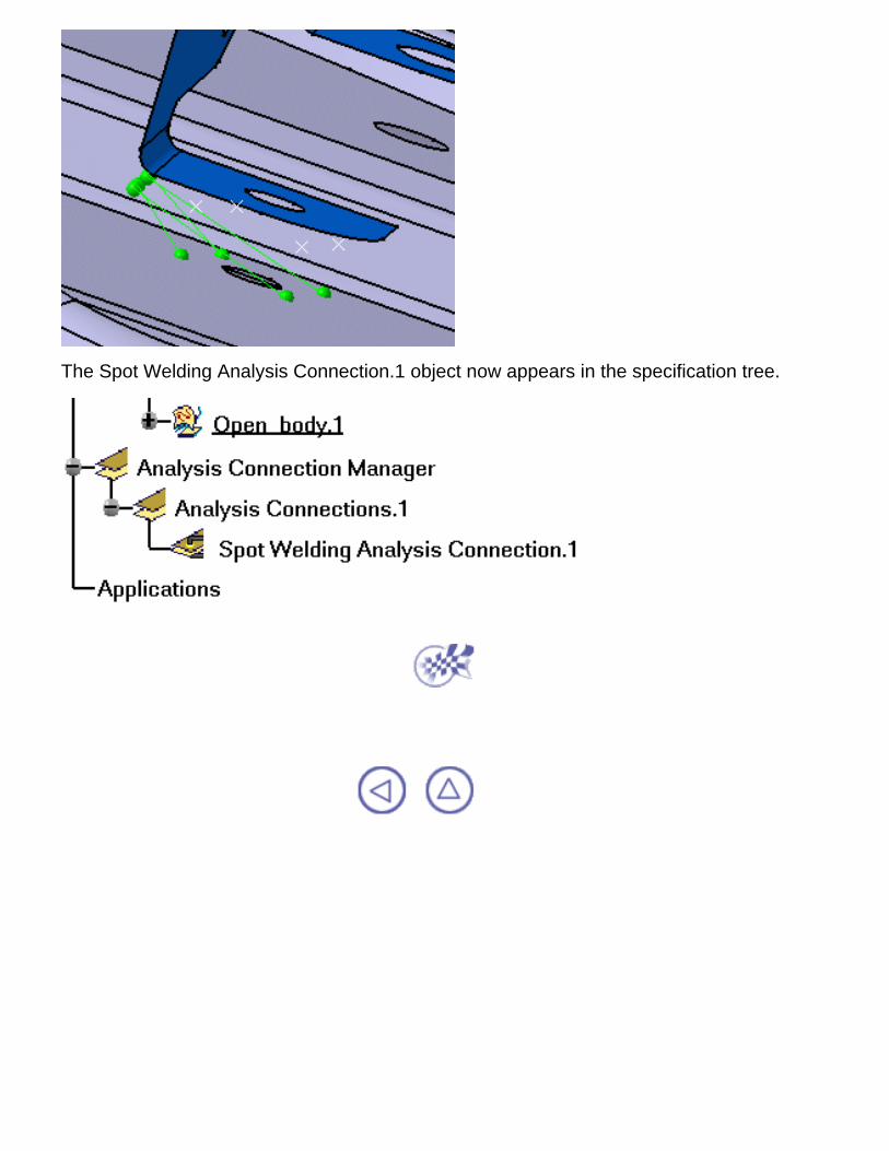
The Spot Welding Analysis Connection.1 object now appears in the specification tree.

Property Connections
Property connections are assembly connections used to specify the boundaryinteraction between bodies in an assembled system. Once the geometric assemblypositioning constraints are defined at the Product level, the user can specify thephysical nature of the constraints.
Creating Fastened Connections: Fastens bodies together at their common interface.
Creating Slider Connections: Fastens bodies together at their common interface inthe normal direction while allowing them to slide relative to each other in thetangential directions.
Creating Contact Connections: Prevents bodies from penetrating each other at acommon interface
Creating Pressure Fitting Connections: Prevents bodies from penetrating each otherat a common interface
Creating Bolt Tightening Connections: Prevents bodies from penetrating each otherat a common interface
Creating Virtual Rigid Bolt Tightening Connections: Takes into account pre-tensionin a bolt-tightened assembly in which the bolt is not included.
Creating Virtual Spring Bolt Tightening Connections: Specifies the boundaryinteraction between bodies in an assembled system.Creating Rigid Connections: Fastens bodies together at a common rigid interface.
Creating Smooth Connections: Fastens bodies together at a common soft interface.
Creating Spot Welding Connections: Fastens bodies together at a common softinterface.

Creating Fastened Connections
A Fastened Connection is the link between two bodies which are fastenedtogether at their common boundary, and will behave as if they were a single body. From afinite element model viewpoint, this is equivalent to the situation where the corresponding nodesof two compatible meshes are merged together. However, since bodies can be meshedindependently, the Fastened Connection is designed to handle incompatible meshes.
The Fastened Connection relations take into account the elastic deformability of the interfaces.
The program proceeds as follows:each node of the finer surface mesh is projected parallel to the local outer normal of thefirst surface onto the second surface mesh.a projection point is located whenever possible at the intercept of the projection directionwith the second surface mesh (extrapolated at the face boundary by roughly half anelement width). if a projection point exists, the start node is connected by a kinematical spider element toall nodes of the element face on which the projection point has landed.a set of join-type relations (involving interpolation using element shape functions and arig-beam relations) is computed between the start node degree of freedom and theconnected nodes degree of freedom.
Thus, the Fastened Connection generates at most as many spider kinematical elements as thereare nodes on the finer surface mesh for which a projection onto the opposite surface meshexists.
This task shows how to create a Fastened Connection between two parts.
You can use the sample16.CATAnalysis document: you applied constraints to the assembly(Assembly Design workbench).
Make sure you enter the Generative Structural Analysis workbench of the Generative PartStructural Analysis product and create a Finite Element Model containing a Static AnalysisCase from this assembly.
1. Click the Fastened Connection icon
.
The Fastened Connection dialog box isdisplayed.

2. Select the assembly constraintpreviously created in the AssemblyDesign workbench.
The only allowed constraint type isContact between surfaces.
3. Click OK to create the FastenedConnection. A symbol representing the FastenedConnection is visualized on thecorresponding faces.
A Fastened Connection object appears inthe features tree under the active Nodesand Elements objects set.

The Finite Element Model contains two Mesh objects, one for each part of the assembly.The sizes of the two meshes are different as can be seen by comparing the Mesh Sizesymbols.

Creating Slider Connections
A Slider Connection is the l two bodies which are constrained to move together inthe local normal direction at their common boundary, and will behave as if they were allowedto slide relative to each other in the local tangential plane. Since bodies can be meshedindependently, the Slider Connection is designed to handle incompatible meshes.
The Slider Connection relations take into account the elastic deformability of the interfaces.
The program proceeds as follows:each node of the finer surface mesh is projected parallel to the local outer normal of thefirst surface onto the second surface mesh.a projection point is located whenever possible at the intercept of the projection directionwith the second surface mesh (extrapolated at the face boundary by roughly half anelement width). if a projection point exists, the start node is connected by a kinematical spider element toall nodes of the element face on which the projection point has landed.a set of join-type relations (involving interpolation using element shape functions and arig-beam relations) is computed between the start node degrees of freedom and theconnected nodes degrees of freedom.these relations are projected on the local normal direction yielding a single scalar relationbetween the start node degrees of freedom and the connected nodes degrees offreedom.
Thus, the Slider Connection generates at most as many spider kinematical elements as there arenodes on the finer surface mesh for which a projection onto the opposite surface mesh exists.
This task shows how to create a Slider Connection between two parts.
You can use the sample16.CATAnalysis document: you applied constraints to the assembly(Assembly Design workbench).
Make sure you enter the Generative Structural Analysis workbench of the Generative PartStructural Analysis product and create a Finite Element Model containing a Static AnalysisCase from this assembly.

1. Click the Slider Connection icon
. The Slider Connection dialog box isdisplayed.
2. Select an assembly constraintpreviously created in the AssemblyDesign workbench.
The only allowed constraint type isContact between surfaces.
3. Click OK in the Slider Connectiondialog box to create the SliderConnection. A symbol representing the SliderConnection is visualized on thecorresponding faces.

A Slider Connection object appearsin the features tree under the activeNodes and Elements objects set.
The Finite Element Model contains two Mesh objects, one for each part of the assembly.The sizes of the two meshes are different as can be seen by comparing the Mesh Sizesymbols.

Creating Contact Connections
A Contact Connection is the link between two part bodies which are preventedfrom inter-penetrating at their common boundary, and will behave as if they were allowed tomove arbitrarily relative to each other as long as they do not come into contact within auser-specified normal clearance. When they come into contact, they can still separate or sliderelative to each other in the tangential plane, but they cannot reduce their relative normalclearance. Since part bodies can be meshed independently, the Contact Connection is designedto handle incompatible meshes.
The Contact Connection relations take into account the elastic deformability of the interfaces.
The Contact cannot be generated on two surfaces or between a surface and a part.
The program proceeds as follows:each node of the finer body surface mesh is projected parallel to the local outer normal ofthe first surface onto the second surface mesh.a projection point is located whenever possible at the intercept of the projection directionwith the second body surface mesh (extrapolated at the face boundary by roughly half anelement width). if a projection point exists, the start node is connected by a node-to-face element withcontact property to all nodes of the element face on which the projection point has landed.a set of join-type relations (involving interpolation using element shape functions) iscomputed between the projection point degrees of freedom and the degrees of freedom ofthe element face nodes (the projection point virtual degrees of freedom are eliminated inthe process).rigid body kinematical relations are computed between the start node and the projectionnode.after the elimination of the projection point degrees of freedom, a contact relation isgenerated by projecting these relations in the local normal direction yielding a singlescalar inequality between the start node degrees of freedom and the degrees of freedomof the element face nodes, with a right-hand side equal to the user-defined clearance.
Thus, the Contact Connection generates at most as many node-to-face elements with contactproperty as there are nodes on the finer surface mesh for which a projection onto the oppositesurface mesh exists.
This task shows how to create a Contact Connection between two parts.

Open the sample16.CATAnalysis document: you applied constraints to the assembly (AssemblyDesign workbench).
Make sure you enter the Generative Structural Analysis workbench of the Generative PartStructural Analysis product and create a Finite Element Model containing a Static AnalysisCase from this assembly.
1. Click the Contact
Connection icon . The Contact Connection dialogbox is displayed.
The Clearance field can be used to enter an algebric value for the maximum allowed normalclearance reduction:
a positive Clearance value (used to model a known gap between the surfaces) means thatthe surfaces can still come closer until they come in contact. a negative Clearance value (used for instance to model a press-fitted clamp between thesurfaces) means that the surfaces are already too close, and the program will have topush them apart.the default value used for the Clearance represents the actual geometric spacing betweensurfaces.
2. Optionally modify the default value of the Clearance parameter.
3. Select an assemblyconstraint previously created inthe Assembly Designworkbench.

The only allowed constrainttype is Contact between bodysurfaces.
4. Click OK in the ContactConnection dialog box tocreate the ContactConnection. A symbol representing theContact Connection isvisualized on thecorresponding faces.
A Contact Connection objectappears in the specificationtree under the active Nodesand Elements objects set.
The Finite Element Model contains two Mesh objects, one for each part of the assembly.The sizes of the two meshes are different as can be seen by comparing the Mesh Sizesymbols.

Creating Bolt Tightening Connections
As a support, the Bolt Tightening Connection requires a surface contact assemblyconstraint between the bolt thread and the bolt support tapping. Note that both these surfacesshould be coincident.
Surface 1 and surface 2 are supports for the assembly constraint of surface contact type.
A Bolt Tightening Connection is a connection that takes into account pre-tension in bolt-tightenedassemblies. The computation is carried out according to the two-step traditional approach. In thefirst step of the computation, the model is submitted to tension forces relative to bolt tightening byapplying opposite forces on the bolt thread and on the support tapping, respectively. Then, in thesecond step, the relative displacement of these two surfaces (obtained in the first step) isimposed while the model is submitted to user loads. During these two steps, the bolt and thesupport displacements are linked in the direction normal to the bolt axis. Since bodies can bemeshed independently, the Bolt Tightening Connection is designed to handle incompatiblemeshes.
The Contact Connection relations take into account the elastic deformability of the interfaces.
The program proceeds as follows:each node of the finer surface mesh is projected parallel to the local outer normal of thefirst surface onto the second surface mesh.

a projection point is located whenever possible at the intercept of the projection directionwith the second surface mesh (extrapolated at the face boundary by roughly half anelement width). if a projection point exists, the start node is connected by a node-to-face element with BoltTightening property to all nodes of the element face on which the projection point haslanded.a set of join-type relations (involving interpolation using element shape functions) iscomputed between the degrees of freedom of the start node and the degrees of freedomof element face nodes (the projection point virtual degrees of freedom are eliminated inthe process).rigid body kinematical relations are computed between the start node and the nodes ofelement face.after the elimination of the projection point degrees of freedom, these relations are rotatedin a coordinate frame the third vector of which is aligned with the tension direction (boltaxis).two scalar equality relations are generated in the first two directions of the coordinateframe, in order to link the displacement of the start node and the nodes of the elementface in the plane normal to the bolt axis.a cable relation (the reverse of a contact relation) is generated between the start node andthe nodes of element face in the third direction, generating an inequality.
Thus, the Bolt Tightening Connection generates at most as many node-to-face elements withBolt Tightening property as there are nodes on the finer surface mesh for which a projectiononto the opposite surface mesh exists.
This task shows how to create a Bolt Tightening Connection between two parts.
Open the sample05.CATAnalysis document: you applied constraints to the assembly (AssemblyDesign workbench).
Make sure you enter the Generative Structural Analysis workbench of the Generative PartStructural Analysis product and create a Finite Element Model from the assembly prior tobeginning this task.
1. Click the Bolt Tightening Connection icon
.
The Bolt Tightening dialog box is displayed.

2. Select a constraint on the assemblypreviously created in the Assembly Designworkbench.
3. Optionally modify the default value of theforce and orientation parameters.
Choose either the same or the oppositeorientation so that the graphic representation ofthe bolt tightening connection matches the boltdirection.
4. Click OK in the Bolt Tightening dialog box to create the Bolt Tightening Connection.
A symbol representing the Bolt TighteningConnection is visualized on the correspondingfaces.

Bolt Tightening.1 Connection object appears inthe specification tree under Properties.1.

Creating Virtual Rigid Bolt TighteningConnections
Virtual Rigid Bolt Tightening Connections are used to specify the boundary interactionbetween bodies in an assembled system. Once the geometric assembly positioning constraintsare defined at the Product level, the user can specify the physical nature of theconstraints. When creating this connection, both the coincidence constraints and the AnalysisConnections workbench constraints can be selected.
Surface 1 and surface 2 are supports for the assembly constraints of coincidence type.
A Virtual Rigid Bolt Tightening Connection is a connection that takes into account pre-tension ina bolt-tightened assembly in which the bolt is not included. The computation is carried outaccording to the two-step traditional approach. In the first step of the computation, the model issubmitted to tension forces relative to bolt tightening by applying opposite forces on the firstsurface (S1) and the second surface (S2) of the assembly constraint, respectively. Then, in thesecond step, the relative displacement of these two surfaces (obtained in the first step) isimposed while the model is submitted to user loads. During these two steps, the rotations of bothsurfaces and the translations perpendicular to the coincidence constraint axis are linked together,while taking into account the elastic deformability of the surfaces. Since bodies can be meshedindependently, the Virtual Rigid Bolt Tightening Connection is designed to handle incompatible

meshes.
The program proceeds as follows:a central node is created at the centroid of each surface of the assembly constraintreferenced as the support.for each surface/central node couple, a set of mean (constr-n) relations is generated tolink the average displacement of the central node and the nodes of the surface.the first central node is linked rigidly to the duplicata of the second central node.the second central node is linked rigidly to its duplicata except for the translation in thedirection of the coincidence constraint.in the direction of the coincidence constraint, a cable relation (the reverse of a contactrelation) is generated between translation degrees of freedom of the second central nodeand its duplicata.
This task shows how to create a Virtual Rigid Bolt Tightening Connection between two parts.
Open the sample11.CATAnalysis document: you applied constraints to the assembly (AssemblyDesign workbench).
Make sure you enter the Generative Structural Analysis workbench of the Generative PartStructural Analysis product and create a Finite Element Model from the assembly prior tobeginning this task.
1. Click the Virtual Rigid BoltTightening Connection icon .
The Virtual Rigid Bolt Tighteningdialog box is displayed.
2. Select a constraint on theassembly previously created in theAssembly Design workbench.

3. Optionally modify the defaultvalue of the force and orientationparameters.
4. Click OK in the Virtual Rigid Bolt Tightening dialog box to create the Virtual Rigid BoltTightening Connection.
A symbol representing the VirtualRigid Bolt Tightening Connection isvisualized on the correspondingfaces.

Virtual Bolt Tightening.1 Connectionobject appears in the specificationtree under Properties.1.

Creating Virtual Spring Bolt TighteningConnections
Virtual Spring Bolt Tightening Connections are used to specify the boundaryinteraction between bodies in an assembled system. Once the geometric assembly positioningconstraints are defined at the Product level, the user can specify the physical nature of theconstraints. When creating this connection, both the coincidence constraints and the AnalysisConnections workbench constraints can be selected.
Surface 1 and surface 2 are supports for the assembly constraints of coincidence type.
Virtual Spring Bolt Tightening Connection is a connection that takes into account pre-tension in abolt-tightened assembly in which the bolt is not included. The computation is carried outaccording to the two-step traditional approach. In the first step of the computation, the model issubmitted to tension forces relative to bolt tightening by applying opposite forces on the firstsurface (S1) and the second surface (S2) of the assembly constraint, respectively. Then, in thesecond step, the relative displacement of these two surfaces (obtained in the first step) isimposed while the model is submitted to user loads. The Virtual Spring Bolt TighteningConnection takes into account the elastic deformability of the surfaces and since bodies can bemeshed independently, the Virtual Spring Bolt Tightening Connection is designed to handleincompatible meshes.

The program proceeds as follows:a central node is created at the centroid of each surface of the assembly constraintreferenced as the support.for each surface/central node couple, a set of mean rigid body (constr-n) relations isgenerated to link the average displacement of the central nodes and the nodes of thesurface.the first central node is linked to the duplicata of the second central node using atightening element. This element generates:- a set of equality relations linking both nodes according to the rigid body motion except forthe translation in the direction of the element.- a cable inequality relation (the reverse of a contact element) in the direction of theelement. This cable relation is used to enforce the relative displacement of both surfacesat the second step of the computation.the second central node is linked to its duplicata using a spring element the characteristicsof which are defined by the user.
This task shows how to create a Virtual Spring Bolt Tightening Connection between two parts.
You can use the sample14.CATAnalysis document: you applied constraints to the assembly(Assembly Design workbench).
Make sure you enter the Generative Structural Analysis workbench of the Generative PartStructural Analysis product and create a Finite Element Model from the assembly prior tobeginning this task.
1. Click the Virtual Spring BoltTightening Connection icon .
The Virtual Spring Bolt Tighteningdialog box is displayed.

2. Select a constraint on theassembly previously created in theAssembly Design workbench.
3. Optionally modify the defaultvalue of the force and stiffnessparameters.
4. Click OK in the Virtual Spring Bolt Tightening dialog box to create the Virtual Spring BoltTightening Connection.

A symbol representing the VirtualSpring Bolt Tightening Connectionis visualized on the correspondingfaces.
Virtual Spring Bolt Tightening.1Connection object appears in thespecification tree underProperties.1.
Creating Pressure Fitting Connections
The Pressure Fitting Connection uses assembly surface contact constraint as asupport. A Pressure Fitting Connection is the link between two bodies which are assembledin a Pressure Fitting configuration, more precisely when there are interferences or overlapsbetween both parts. Along the surface normal, the connection behaves as a contact connectionwith negative clearance value (positive overlap). The difference lies in the tangential directionswhere both parts are linked together. Since bodies can be meshed independently, the PressureFitting Connection is designed to handle incompatible meshes.
The Pressure Fitting Connection relations take into account the elastic deformability of theinterfaces.
The program proceeds as follows:each node of the finer surface mesh is projected parallel to the local outer normal of thefirst surface onto the second surface mesh.a projection point is located whenever possible at the intercept of the projection directionwith the second surface mesh (extrapolated at the face boundary by roughly half anelement width).if a projection point exists, the start node is connected by a a node-to-face element withcontact property to all nodes of the element face on which the projection point has landed.a set of join-type relations (involving interpolation using element shape functions) iscomputed between the degrees of freedom of the start node and the degrees of freedomof element face nodes (the projection point virtual degrees of freedom are eliminated inthe process).rigid body kinematical relations are computed between the start node and the nodes ofelement face.these relations are rotated in a coordinate system the third vector of which corresponds tothe normal of the local surface.after the elimination of the projection point degrees of freedom, a pressure fitting relationis generated between the start node and the projected node, transforming the scalarequality relation into an inequality relation with a right-hand side equal to the minususer-defined overlap.two scalar equality relations are generated in the tangential plane to link the tangentialdisplacement of the start node and its projection.
Thus, the Pressure Fitting Connection generates at most as many node-to-face elements withPressure Fitting property as there are nodes on the finer surface mesh for which a projectiononto the opposite surface mesh exists.
This task shows how to create a Pressure Fitting Connection between two parts.

Open the sample12.CATAnalysis document: you applied constraints to the assembly (AssemblyDesign workbench).
Make sure you enter the Generative Structural Analysis workbench of the Generative PartStructural Analysis product and create a Finite Element Model from the assembly prior tobeginning this task.
1. Click the Pressure FittingConnection icon .
The Pressure Fitting dialog box isdisplayed.
The Overlap field can be used to enter an algebraic value for the maximum allowed normalclearance reduction:
a positive Overlap value (used for instance to model a press-fitted clamp between thesurfaces) means that the surfaces are already too close, and the program will have topush them apart.a negative Overlap value (used to model a known gap between the surfaces) means thatthe surfaces can still come closer until they come in contact. the default value used for the Overlap represents the actual geometric spacing betweensurfaces.
The overlap indicates the interference between both parts. It is intended to be positive.
2. Select an assembly constraintpreviously created in the AssemblyDesign workbench.

3. Optionally modify the defaultvalue of the overlap parameter. Inthis case, enter 0.001mm.
4. Click OK to create the PressureFitting Connection. A symbol representing the PressureFitting Connection is visualized onthe corresponding faces.
Pressure Fitting.1 Connectionobject appears in the specificationtree under Properties.1.

Creating Rigid Connections
A Rigid Connection is the link between two bodies which are stiffened andfastened together at their common boundary, and will behave as if their interface wasinfinitely rigid. Since bodies can be meshed independently, the Rigid Connection is designed tohandle incompatible meshes.
The Rigid Connection relations do not take into account the elastic deformability of theinterfaces.
The program proceeds as follows:a central node is created at the midpoint between the centroids of the two systems ofpoints represented by the nodes of the two meshes.this node is connected by a rig-beam element to each node of the first and of the secondmeshes. a set of rig-beam relations is generated between the central node degree of freedom andthe connected nodes degree of freedom.
Thus, the Rigid Connection generates as many rig-beam kinematical elements as there arenodes on the two surface meshes.
This task shows how to create a Rigid Connection between two parts.
Open the sample17.CATAnalysis document: you applied constraints to the assembly (AssemblyDesign workbench).
Make sure you enter the Generative Structural Analysis workbench of the Generative PartStructural Analysis product and create a Finite Element Model containing a Static AnalysisCase from this assembly.
1. Click the Rigid Connection icon
. The Rigid Connection dialog box isdisplayed.

2. Select the Coincidence assemblyconstraint previously created in theAssembly Design workbench.
The allowed assembly constrainttypes are Coincidence, Offset andAngle.
3. Click OK in the Rigid Connectiondialog box to create the RigidConnection. A symbol representing the RigidConnection is visualized on thecorresponding faces.
A Rigid Connection object appears inthe features tree under the activeNodes and Elements objects set.

The Finite Element Model contains two Mesh objects, one for each part of the assembly.The sizes of the two meshes are different as can be seen by comparing the Mesh Sizesymbols.

Creating Smooth Connections
A Smooth Connection is the link between two bodies which are fastened togetherat their common boundary, and will behave approximately as if their interface was soft. Sincebodies can be meshed independently, the Smooth Connection is designed to handleincompatible meshes.
The Smooth Connection relations take approximately into account the elastic deformability of theinterfaces. The approximation is based on a least squares fit of a slave node degree of freedomrigidly linked to the master nodes (element shape functions are ignored).
The program proceeds as follows:a central node is created at the midpoint between the centroids of the two systems ofpoints represented by the nodes of the two meshes.this node is connected by two spider elements to all nodes of the first and of the secondmeshes. a set of mean (constr-n) relations is generated between the central node degree offreedom and the connected nodes degree of freedom.
Thus, the Smooth Connection generates two spider kinematical elements.
This task shows how to create a Smooth Connection between two parts.
Open the sample17.CATAnalysis document: you applied constraints to the assembly (AssemblyDesign workbench).
Make sure you enter the Generative Structural Analysis workbench of the Generative PartStructural Analysis product and create a Finite Element Model containing a Static AnalysisCase from this assembly.
1. Click the Smooth Connection icon
. The Smooth Rigid dialog box isdisplayed.

2. Select the Coincidence assemblyconstraint previously created in theAssembly Design workbench.
The allowed assembly constraint typesare Coincidence, Offset and Angle.
3. Click OK to create the SmoothConnection. A symbol representing the SmoothConnection is visualized on thecorresponding faces.
A Smooth Connection object appears inthe features tree under the active Nodesand Elements objects set.
The Finite Element Model contains two Mesh objects, one for each part of the assembly.The sizes of the two meshes are different as can be seen by comparing the Mesh Sizesymbols.

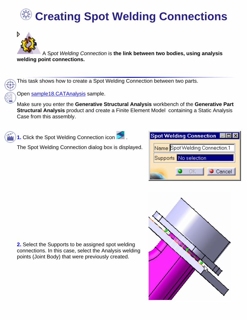
Creating Spot Welding Connections
A Spot Welding Connection is the link between two bodies, using analysiswelding point connections.
This task shows how to create a Spot Welding Connection between two parts.
Open sample18.CATAnalysis sample.
Make sure you enter the Generative Structural Analysis workbench of the Generative PartStructural Analysis product and create a Finite Element Model containing a Static AnalysisCase from this assembly.
1. Click the Spot Welding Connection icon .
The Spot Welding Connection dialog box is displayed.
2. Select the Supports to be assigned spot weldingconnections. In this case, select the Analysis weldingpoints (Joint Body) that were previously created.

The Spot Welding Connection dialog box is updated.
3. Click OK in the Spot Welding Connection dialog box
A Spot Welding Connection object appears in thespecification tree under the Properties objects set.


Workbench DescriptionThis section contains the description of the icons and menus which are specific to theGenerative Assembly Structural Analysis product, either:
from the Generative Part Structural Analysis workbench
or
from the Analysis Connections workbench
The menu items can be found on the top border of your analysis document.
The icons are grouped in toolbars, which can be found on the right and bottom border ofyour analysis document.

Property Connections ToolbarAnalysis Connection Toolbar

Property Connections Toolbar
The Mesh Specification toolbar (Generative Assembly Structural Analysis workbench)gives access to the following tools for defining Property Connections and AdvancedConnections:
ConnectionsSee Fastened Connections
See Slider Connections
See Contact Connections
See Rigid Connections
See Smooth Connections
Advanced Connections
See Pressure Fitting Connections
See Bolt Tightening Connections
See Virtual Rigid Bolt Tightening Connections
See Virtual Spring Bolt Tightening Connections
See Spot Welding Connections

Analysis Connections Toolbar
The Analysis Connections toolbar (Analysis Connections workbench) gives you directaccess to the following tools for defining Analysis Connections:
Analysis Connections
See Face Face Connections
See Distant Connections
See Welding Points Connections

IndexA
Analysis connections
distant connection
face face connection
welding point connection
Bbolt tightening connection
Cconnections
bolt tightening connection
contact connection
distant Analysis connection
face face Analysis connection
fastened connection
pressure fitting connection
rigid connection
rigid virtual bolt tightening
slider connection

smooth connection
spot welding connection
virtual spring bolt tightening
welding point Analysis connection
contact connection
Ffastened connection
face-to-face connection
Ppressure fitting connection
property connections
bolt tightening connection
contact connection
fastened connection
pressure fitting connection
rigid connection
rigid virtual bolt tightening
slider connection
smooth connection
virtual spring bolt tightening
Rrigid connection
rigid virtual bolt tightening connection
virtual spring bolt tightening connection
Sslider connection
smooth connection
spot welding connection
Wwelding point Analysis connection
workbench