generally, the broad definition of a sensors/ transducers
TRANSCRIPT

Q3. Write a short note on classification of transducers.
Nearly all engineering applications require some form of measuring, controlling, calculating,
communicating and recording of data. These operations, grouped or isolated, are inherent in
measurement instrumentation. If the equipment is to be used for the quantitative analysis of an
analogue signal, i.e., a naturally occurring signal, the following must be taken into consideration:
The analogue signal to be measured may be temperature, pressure, humidity,
velocity, flow rate, linear motion, position, amongst others. This signal must be
converted into an analogue electrical signal, typically voltage or current, and then
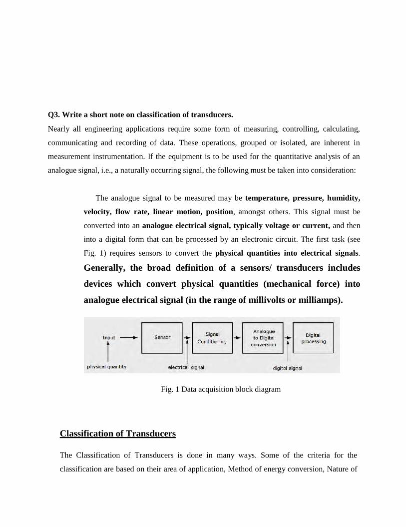
into a digital form that can be processed by an electronic circuit. The first task (see
Fig. 1) requires sensors to convert the physical quantities into electrical signals.
Generally, the broad definition of a sensors/ transducers includes
devices which convert physical quantities (mechanical force) into
analogue electrical signal (in the range of millivolts or milliamps).
Fig. 1 Data acquisition block diagram
Classification of Transducers
The Classification of Transducers is done in many ways. Some of the criteria for the
classification are based on their area of application, Method of energy conversion, Nature of

output signal, According to Electrical principles involved, Electrical parameter used,
principle of operation, & Typical applications.
The transducers can be classified broadly
i. On the basis of transduction form used
ii. As primary and secondary transducers
iii. As active and passive transducers
iv. As transducers and inverse transducers.
Broadly one such generalization is concerned with energy considerations wherein they are
classified as active & Passive transducers.
A component whose output energy is supplied entirely by its input signal (physical
quantity under measurement) is commonly called a ‘passive transducer’. In other words the
passive transducers derive the power required for transduction from an auxiliary source.
Active transducers are those which do not require an auxiliary power source to produce
their output. They are also known as self generating type since they produce their own
voltage or current output.
Some of the passive transducers ( electrical transducers), their electrical parameter
(resistance, capacitance, etc), principle of operation and applications are listed below.
The table 1 & 2 list the principle of operation and applications of the resistance transducers
respectively.
The capacitive, inductive, etc transducers are listed next.

Table 1. Type & principle of operation of resistance transducers
Table 1. Type & applications of resistance transducers

Capacitance Transducers
1. Variable capacitance pressure gage -
Principle of operation: Distance between two parallel plates is varied by an externally applied
force
Applications: Measurement of Displacement, pressure
2. Capacitor microphone
Principle of operation: Sound pressure varies the capacitance between a fixed plate and a
movable diaphragm. Applications: Speech, music, noise
3. Dielectric gage
Principle of operation: Variation in capacitance by changes in the dielectric.
Applications: Liquid level, thickness
Inductance Transducers
1. Magnetic circuit transducer
Principle of operation: Self inductance or mutual inductance of ac-excited coil
is varied by changes in the magnetic circuit.
Applications: Pressure, displacement
2. Reluctance pickup
Principle of operation: Reluctance of the magnetic circuit is varied by changing the
position of the iron core of a coil.
Applications: Pressure, displacement, vibration, position
3. Differential transformer
Principle of operation: The differential voltage of two secondary windings of a
transformer is varied by positioning the magnetic core through an externally applied
force.
Applications: Pressure, force, displacement, position
4. Eddy current gage
Principle of operation: Inductance of a coil is varied by the proximity of an eddy current
plate.
Applications: Displacement, thickness
5. Magnetostriction gage
Principle of operation: Magnetic properties are varied by pressure and stress.
Applications: Force, pressure, sound
Voltage and current Transducers
1. Hall effect pickup
Principle of operation: A potential difference is generated across a semiconductor
plate (germanium) when magnetic flux interacts with an applied current.
Applications: Magnetic flux, current
2. Ionization chamber
Principle of operation: Electron flow induced by ionization of gas due to radioactive
radiation. Applications: Particle counting, radiation
3. Photoemissive cell
Principle of operation: Electron emission due to incident radiation on photoemissive
surface. Applications: Light and radiation
4. Photomultiplier tube
Principle of operation: Secondary electron emission due to incident radiation on
photosensitive cathode.
Applications: Light and radiation, photo-sensitive relays
Self-Generating Transducers (No External Power) – Active Transducers
1. Thermocouple and thermopile
Principle of operation: An emf is generated across the junction of two dissimilar
metals or semiconductors when that junction is heated.
Applications: Temperature, heat flow, radiation
2. Moving-coil generator
Principle of operation: Motion of a coil in a magnetic field generates a voltage.
Applications: Velocity. vibration
3. Piezoelectric pickup
An emf is generated when an external force is applied to certain crystalline materials,
such as quartz
Sound, vibration. acceleration, pressure changes
4. Photovoltaic cell
Principle of operation: A voltage is generated in a semi-conductor junction device when
radiant energy stimulates the cell
Applications: Light meter, solar cell
Q4. Explain the construction and working of LVDTLinear Variable Differential Transformer – LVDT Transducer
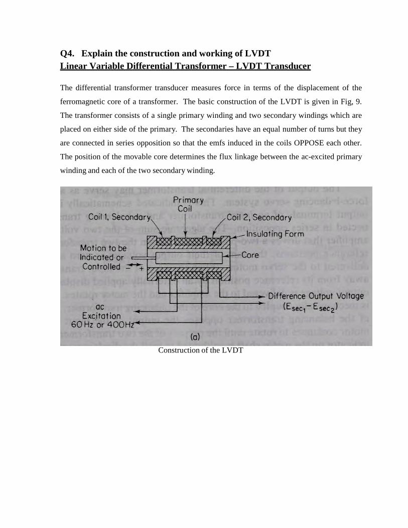
The differential transformer transducer measures force in terms of the displacement of the
ferromagnetic core of a transformer. The basic construction of the LVDT is given in Fig, 9.
The transformer consists of a single primary winding and two secondary windings which are
placed on either side of the primary. The secondaries have an equal number of turns but they
are connected in series opposition so that the emfs induced in the coils OPPOSE each other.
The position of the movable core determines the flux linkage between the ac-excited primary
winding and each of the two secondary winding.
Construction of the LVDT
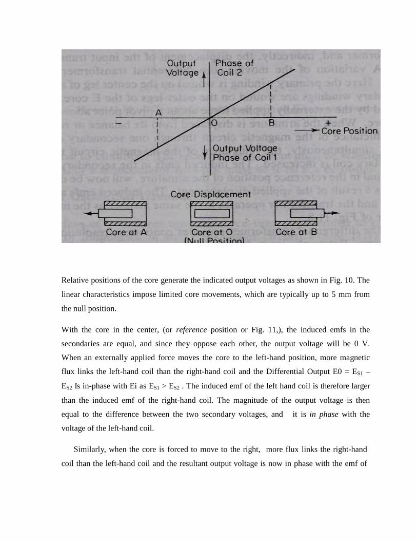
Relative positions of the core generate the indicated output voltages as shown in Fig. 10. The
linear characteristics impose limited core movements, which are typically up to 5 mm from
the null position.
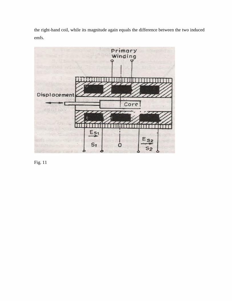
With the core in the center, (or reference position or Fig. 11,), the induced emfs in the
secondaries are equal, and since they oppose each other, the output voltage will be 0 V.
When an externally applied force moves the core to the left-hand position, more magnetic
flux links the left-hand coil than the right-hand coil and the Differential Output E0 = ES1 –
ES2 Is in-phase with Ei as ES1 > ES2 . The induced emf of the left hand coil is therefore larger
than the induced emf of the right-hand coil. The magnitude of the output voltage is then
equal to the difference between the two secondary voltages, and it is in phase with the
voltage of the left-hand coil.
Similarly, when the core is forced to move to the right, more flux links the right-hand
coil than the left-hand coil and the resultant output voltage is now in phase with the emf of
the right-hand coil, while its magnitude again equals the difference between the two induced
emfs.
Fig. 11

Fig. 12
Ideally the output voltage at the null position should be equal to zero. In actual practice there
exists a small voltage at the null position. (refer Fig. 12). This may be on account of
presence of harmonics in the input supply voltage and also due to harmonics produced
in the output voltage due to use of iron Displacement core. There may be either an
incomplete magnetic or electrical unbalance or both which result in a finite output voltage
at the null position. This finite residual voltage is generally less than 1% of the maximum
output voltage in the linear range. Other causes of residual voltage are stray magnetic fields
and temperature effects.
Applications of LVDT
Acting as a secondary transducer it can be used as a device to measure force, weight and
pressure etc. The force measurement can be done by using a load cell as the primary
transducer while fluid pressure can be measured by using Bourdon tube which acts as
primary transducer. The force or the pressure is converted into a voltage.
In these applications the high sensitivity of LVDTs is a major attraction.
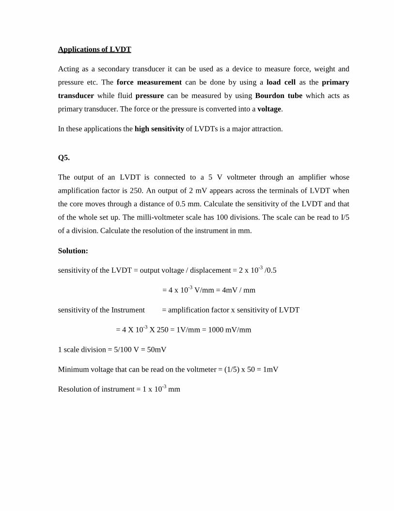
Q5.
The output of an LVDT is connected to a 5 V voltmeter through an amplifier whose
amplification factor is 250. An output of 2 mV appears across the terminals of LVDT when
the core moves through a distance of 0.5 mm. Calculate the sensitivity of the LVDT and that
of the whole set up. The milli-voltmeter scale has 100 divisions. The scale can be read to I/5
of a division. Calculate the resolution of the instrument in mm.
Solution:
sensitivity of the LVDT = output voltage / displacement = 2 x 10⁻³ /0.5
= 4 x 10⁻³ V/mm = 4mV / mm
sensitivity of the Instrument = amplification factor x sensitivity of LVDT
= 4 X 10-3 X 250 = 1V/mm = 1000 mV/mm
1 scale division = 5/100 V = 50mV
Minimum voltage that can be read on the voltmeter = (1/5) x 50 = 1mV
Resolution of instrument = 1 x 10⁻³ mm