general technical guide for water reservoirs · 2016-06-23 · general technical guide for water...
TRANSCRIPT

General technical guide for water reservoirs | 1
www.firestonebpe.com
GeomembraneGeneral Technical Guide for Water Reservoirs

General technical guide for water reservoirs | 2
I This brochure is meant only to highlight Firestone’s products and specifications. Information is subject to change without notice. All products and specifications are listed in
approximate weights and measurements. For complete product and detail information, please refer to the technical information posted on www.firestonebpe.com. Firestone
takes responsibility for furnishing quality materials which meet Firestone’s published product specifications. As neither Firestone itself nor its representatives practice
architecture, Firestone offers no opinion on and expressly disclaims any responsibility for the soundness of any structure on which its products may be applied. If questions
arise as to the soundness of a structure or its ability to support a planned installation properly, the owner should obtain opinions of competent structural engineers before
proceeding. Firestone accepts no liability for any structural failure or for resultant damages and no Firestone Representative is authorized to vary this disclaimer. I
© Firestone Building Products. All rights reserved • GEO_LIT_TGL_06-2013_EN_00008 - 11/13
Ikaroslaan 75 I 1930 Zaventem I Belgium | Phone +32(0)2 711 44 50 I Fax +32(0)2 721 27 18 I [email protected] I www.firestonebpe.com

General technical guide for water reservoirs | 3
Table of contents
Introduction ......................................................................................................................................................................... 5
1. Firestone EPDM Geomembrane ................................................................................................................................... 6
1.1. Why Firestone, Why EPDM ...................................................................................................................................... 6
1.2. Composition ........................................................................................................................................................... 7
1.3. Production .............................................................................................................................................................. 8
1.4. Splicing mechanism ................................................................................................................................................. 9
1.5. Review of technical performances ......................................................................................................................... 10
1.6. Applications .......................................................................................................................................................... 13
2. Design considerations ................................................................................................................................................. 14
2.1. Geomembrane selection ....................................................................................................................................... 14
2.2. Site selection ......................................................................................................................................................... 15
2.3. Geometry of the reservoir...................................................................................................................................... 17
2.4. Anchoring the geomembrane ............................................................................................................................... 22
2.5. Foundation ........................................................................................................................................................... 25
2.6. Support structure .................................................................................................................................................. 25
2.7. Drainage system .................................................................................................................................................... 27
2.8. Top protection of the geomembrane ..................................................................................................................... 33
2.9. Inlet/outlet of the water ........................................................................................................................................ 36
2.10. Wind uplift............................................................................................................................................................ 42
2.11. Dimensional movements ....................................................................................................................................... 43
2.12. Panel and seam layout .......................................................................................................................................... 44
2.13. Operation facilities ................................................................................................................................................ 44
2.14. Risk level ............................................................................................................................................................... 45
2.15. Legislation ............................................................................................................................................................. 45
3. Installation ................................................................................................................................................................... 46
3.1. Site preparation .................................................................................................................................................... 46
3.2. Earthworks ............................................................................................................................................................ 46
3.3. Water and gas drainage ........................................................................................................................................ 50
3.4. Anchor trench ....................................................................................................................................................... 50
3.5. Geotextile ............................................................................................................................................................. 51
3.6. Geomembrane installation .................................................................................................................................... 51
3.7. Timing .................................................................................................................................................................. 60
3.8. Weather conditions ............................................................................................................................................... 61
3.9. Top protection installation ..................................................................................................................................... 62
3.10. Details ................................................................................................................................................................... 62
3.11. Safety ................................................................................................................................................................... 71
Please contact Firestone
Please contact Firestone
Please contact Firestone
Please contact Firestone
Please contact Firestone
Please contact Firestone
Please contact Firestone
Please contact Firestone
Please contact Firestone
Please contact Firestone
Please contact Firestone
Please contact Firestone
Please contact Firestone
Please contact Firestone
Please contact Firestone
Please contact Firestone
Please contact Firestone
Please contact Firestone
Please contact Firestone
Please contact Firestone
Please contact Firestone
Please contact Firestone

General technical guide for water reservoirs | 4
4. Control and quality assurance .................................................................................................................................... 72
4.1. Control ................................................................................................................................................................. 72
4.2. Acceptance of work .............................................................................................................................................. 78
4.3. Monitoring devices ................................................................................................................................................ 79
4.4. Inspections and maintenance ................................................................................................................................ 79
4.5. Repair guidelines ................................................................................................................................................... 81
5. Application specifications ........................................................................................................................................... 85
5.1. Dung pits .............................................................................................................................................................. 85
5.2. High altitude reservoirs .......................................................................................................................................... 85
5.3. Artificial wetlands ................................................................................................................................................. 86
6. Detail drawings ........................................................................................................................................................... 87
6.1. Lap Splices ............................................................................................................................................................ 88
6.2. Corners ................................................................................................................................................................. 91
6.3. Penetrations .......................................................................................................................................................... 96
6.4. Terminations ....................................................................................................................................................... 100
6.5. Anchoring ........................................................................................................................................................... 106
6.6. Membrane cover ................................................................................................................................................. 110
7. Technical information sheet (TIS) ............................................................................................................................. 113
7.1. Membranes ......................................................................................................................................................... 114
7.2. Adhesives and sealants ........................................................................................................................................ 116
7.3. QuickSeam accessories ........................................................................................................................................ 121
7.4. Battens and Bars ................................................................................................................................................. 127
8. Enclosures .................................................................................................................................................................. 130
8.1. Chemical resistance chart .................................................................................................................................... 130
8.2. Non-exhaustive list of plants producing rhizomes ................................................................................................ 132
9. Bibliography .............................................................................................................................................................. 133
Please contact Firestone
Please contact Firestone
Please contact Firestone
Please contact Firestone
Please contact Firestone
Please contact Firestone
Please contact Firestone
Please contact Firestone
Please contact Firestone
Please contact Firestone
Please contact Firestone
General technical guide for water reservoirs | 5
IntroductionGeomembranes are the most widely used products for solid waste containment (such as landfill liners), mining and water
containment applications. They are designed as relatively impermeable liners for use in a variety of applications.
This manual contains information on lining systems using Firestone EPDM Geomembranes. Apart from general
recommendations on the use and installation of the EPDM Geomembrane, it also gives information on design, site preparation,
excavation works, control and quality assurance.
Generally, for simple projects, the design may be carried out by the owner or the contractor.
However, in the case of larger reservoirs the design is often considerably more complex, and the contractor should request the
advice of a specialist in hydraulic structures. The specialist should be able to answer specific questions on excavation, drainage,
protection of the liner, etc.
Before initiating any project, a study of the site should be carried out for the purpose of obtaining correct information
regarding :
• Nature of the soil
• Presence of cavities (chalk rocks, chalky soil,...)
• Depth and variation of the groundwater level
• Presence of gases in the soil (peat, organic matter,...)
• Risk of differential settling (poorly consolidated soil, recent backfill,...)
• Risk of internal erosion (karst soil, sand,...)
In any case, the rules of soil mechanics must be complied with in order to ensure the stability of the support and consequently,
a durable lining system. All these subjects are covered in chapter 2 of this manual.
Chapter 3 deals with the installation of the Firestone Geomembrane System. This section covers site preparation, compaction
of the soil, installation of the drainage, installation of the Geomembrane, splicing and execution of details.
Chapter 4 is dedicated to making sure the installation is done as per the Firestone specifications and explains different control
procedures and repair techniques.
Some installation guidelines are specific to a certain type of application and these are highlighted in chapter 5.
Finally, the manual is completed with:
• Chapter 6: Drawings
• Chapter 7: Technical Information Sheets
• Chapter 8: Chemical resistance chart
The Firestone Geomembrane must be installed by an authorized Firestone contractor in accordance with Firestone’s specifications.
It is also essential that all local regulations and codes are complied with.

General technical guide for water reservoirs | 6
1. Firestone EPDM Geomembrane
1.1. Why Firestone, Why EPDM
Firestone has been a world-recognized leader in rubber polymer technology for over 100 years. Building on this broad
legacy, Firestone Building Products has become a global leading manufacturer of rubber roofing and waterproofing systems.
Firestone Building Products is part of the Bridgestone Corporation, the world’s largest tire and rubber company.
The first use of Firestone rubber membranes in irrigation reservoirs located in the South of Spain dates from 1973. Today,
even after many years of exposition to UV and ozone, the rubber liner continues to provide a dependable waterproof
solution. Today, Firestone has thousands of references worldwide which are the living proof of the exceptional performance of
Firestone EPDM Geomembrane.
Firestone offers contractors educational programs covering all aspects of an EPDM Geomembrane System installation. The
company’s installation support extends on the job site where field technicians offer training, professional assistance and quality
inspection of finished installations.
The company’s state-of the-art EPDM manufacturing facilities follow stringent quality control guidelines from raw
material selection to finished product testing. Our operations have been certified according to ISO 9001 and ISO 14001.
Firestone EPDM Geomembrane has obtained the CE-marking and has been tested and certified to various international and
national standards, including the French ASQUAL certification.
Firestone EPDM Geomembrane is a rubber liner offering unique features and benefits for a wide variety of agricultural, industrial
and commercial applications.
• Long term durability (UV and ozone).
• High elasticity (> 300% of elongation).
• High flexibility even at low temperature (down to -45°C).
• Excellent puncture resistance.
• High friction angle (27°).
• Chemically inert.
• Environmentally friendly.
• …
More detailed information on Firestone EPDM Geomembrane properties is given in chapter 1.5.

General technical guide for water reservoirs | 9
1.4. Splicing mechanism
There are two types of seams in the Firestone EPDM lining systems:
• Factory seams: splicing is performed during the production of the EPDM sheet prior to vulcanization. The material of the
seam is homogeneous and 100% cured.
• Field seams: splicing is performed on site using a Quick Seam Splice Tape.
When leaving the factory,
the Firestone EPDM Geomembrane is a thermoset
material. Welding techniques or solvents cannot be
used to melt the EPDM membrane. Two adjoining
sheets therefore have to be joined with a material
that is chemically active, the self-adhesive QuickSeam
Splice Tape combined with the QuickPrime Plus primer.
A successful splice will depend on a sound contact of the
bonding agent and the membrane. For this reason the
surface has to be prepared with utmost care.
The surface of the EPDM sheet examined under a microscope,
is not completely smooth - it looks like an orange skin, full
of small irregularities and ridges. It is important to observe
that the surface is not clean but covered with dust and talc.
By scrubbing the surface with a scrubber pad, soaked with
QuickPrime Plus, the irregularities are changed, creating a
receptive surface for contact.
The active molecules of the QuickPrime Plus are carried
by a solvent, which provides a proper coating and a deep
penetration of the components into the surface irregularities.
When most of the solvent is evaporated, the QuickPrime
Plus is still chemically active and provides a tacky surface
for the Splice Tape to be installed to complete the splicing
procedure.
In addition to the adhesion mechanism (attraction between
adhesive and surface molecules), the membrane surfaces
are mechanically interlocked by the components of the
QuickPrime Plus. Both mechanisms create high-resistance
molecular links. It will take 7 to 28 days for the QuickPrime
Plus to complete the curing process.
Experience to date has demonstrated that the EPDM
field splicing technique using QuickSeam Splice Tape and
QuickPrime Plus is very “friendly” and durable.
This installation method satisfies the normal day-to-day
variations such as climatic conditions, different applicators
and job conditions.
Figure 3: Splicing mechanism

General technical guide for water reservoirs | 13
1.6. Applications
Firestone EPDM Geomembrane is used successfully in a wide variety of applications worldwide:
• Agricultural applications
- Irrigation reservoirs and canals
- Agricultural ponds and dung pits
- Aquaculture ponds
- Algae ponds
- Hydroponic farming
- Ensilage covers
• Environmental protection:
- Constructed wetlands
- Waste water reservoirs
- Storm water reservoirs
- Landfill capping
- Mining waste containment
• Industrial applications:
- Settlement lagoons
- Artificial snow reservoirs
- Hydroelectric reservoirs and canals
- Fire reservoirs
• Artificial lakes
The recommendations in this manual mainly apply to water reservoirs. Some applications need specific recommendations which
are described in chapter 5.
Non-acceptable applications for the Firestone EPDM Geomembrane are:
• Applications where gas generation or hydrostatic pressure could disturb the functioning of
the Firestone EPDM Geomembrane.
• Applications where the Firestone EPDM Geomembrane could come in contact with chemical substances that affect
the EPDM Geomembrane.

General technical guide for water reservoirs | 14
2. Design considerationsThere is no single solution to build a water reservoir. Before constructing a water reservoir, it is essential to carry out some site
visits and specific analysis in order to optimize the location of the installation, its characteristics (size, shape, etc.) and the means
to be employed (materials used, etc.). The following are some of the important points that need to be considered:
• Project basics:
- Volume of liquid to store
- Characteristics of the stored liquid (chemical composition, temperature, etc.)
• Site environment:
- Available space (geometric constraints)
- Nature of the soil (composition, stability)
- Topography
- Depth of underground water
- Risk factor (human, environmental, economical)
- Materials availability
• Methods of use and maintenance:
- Expected in-use constraints
- Filling/emptying
- Water speed
- Cleaning
2.1. Geomembrane selection
2.1.1. Panel size
Once the final shape of the reservoir has been designed, the panel size is chosen based on the panel and seam layout drawing.
The goal is to reduce losses and facilitate the installation process (limit on-site splicing and cuts). The design process of the panel
and seam layout is described in chapter 2.11.
The Firestone EPDM Geomembrane is factory-assembled into large, fully vulcanized seamless membranes.
The Firestone EPDM Geomembrane is supplied in the following dimensions:
Thickness 1.1 mm (.045”) 1.5 mm (.060”)
Max. surface 930.25 m² (15,25 m x 61,0 m) 744.5 m² (12,20 m x 61,0 m)
Length 30.48 m, 60.96 m 15.24 m, 30.48 m, 45.72 m, 60.96 m
Width 3.05 m, 6.10 m, 7.62 m, 9.15 m, 12.20 m, 15.25m
Note: Not all roll widths are available in all possible roll lengths
Table 2: Panel sizes
Depending on the panel size, the rubber sheets are folded and packaged onto 1.83 m, 2.13 m, 2.44 m, 3.35 m or 4.27 m long
cores. It is strongly recommended that the longest available core is always used in order to minimize fold lines and wrinkles in
the sheet.
2.1.2. Thickness
The Firestone EPDM Geomembrane is produced in two thicknesses: 1.1 mm and 1.5 mm (Note: the 1.0 mm thick
Firestone EPDM PondGard is specifically designed for decorative pond applications and is not treated in this guide).
Increasing the thickness of an EPDM geomembrane will result in a higher puncture resistance.
The Firestone EPDM Geomembrane 1.5 mm puncture resistance is almost 30% higher than the Firestone EPDM Geomembrane
1.1 mm. The thickness of the geomembrane has to be related to the project specificity. The use of a thicker EPDM geomembrane
can be required for lining applications with an increased security level due to potential human or environmental risks
and/or for applications requiring a higher mechanical performance because of high applied pressure (water, ice crust),
specific uses, maintenance operations, surface irregularities, expected differential settlement, covering (risk of damage during
the installation of the cover)…
A double layer of geomembrane can be installed on sites where no leakage can be tolerated (subsoil presents risks of internal
erosion or dissolution, storage of polluted liquids in a environmentally protected zone, etc.). Between the two geomembranes
a geocomposite drainage system must be connected to a leak detection system. In some specific applications, national
legislations can ask for a double layer, but it is very exceptional.

General technical guide for water reservoirs | 15
2.1.3. Chemical compatibility
Due to its chemical composition and production process (vulcanization) the Firestone EPDM Geomembrane has a wide
spectrum of chemical resistance. Nevertheless, Firestone EPDM Geomembrane cannot be used to store chemicals. When
another product than clear water is expected, it is essential to contact the Firestone Technical Department to confirm the
compatibility of the EPDM geomembrane with the product stored. Some products, such as hydrocarbons and greases, are not
compatible with EPDM geomembranes.
A chemical resistance chart for the Firestone EPDM Geomembrane is enclosed (see enclosure 8.1). The enclosed tables are to
be used solely in case of accidental contact.
The effect of chemicals on the membrane is highly dependent on the following factors:
• Temperature: an increase in temperature accelerates the chemical reaction and affects the durability of any type of
geomembrane.
• pH: in standard conditions, EPDM cannot be used when pH is lower than 4 and higher than 10.
• Type and concentration of the chemicals.
• Duration and frequency of exposure.
• Liner installation quality and details: in certain conditions, tensions in the installed liner can affect the life time.
It is also very important to make sure that the support structure or the cover material are chemically compatible with the
geomembrane. In case of suspected pollution of the ground (hydrocarbon smell when excavating, old factory site, etc.), it is
strongly recommended that a chemical analysis of ground samples and, if required, some compatibility tests are conducted.
2.2. Site selection
When selecting the construction site, several elements must be considered to ensure long-term performance of the lining
system and to avoid any future problems. Site selection is the responsibility of a specialist engineer.
The following is a general overview of a few of the critical site selection parameters which should be investigated.
2.2.1. Preliminary studies of the site
Firstly, all existing data on the site will be collected and studied: topographical and geological maps, existing geotechnical
studies of the zone, historical data (previous activities, old aerial pictures and maps, exceptional natural events, etc.), pluviometry
and wind statistics, among other things.
A detailed visual inspection of the site will be carried out by experienced engineers and geologists. The specifics of the site will
be identified: topography, geology, hydrology, vegetation, existing infrastructure, accessibility, surroundings. Special attention
will need to be given to detect former landfill and dump areas.
In order to learn about the characteristics of the ground located inside the limits of the project and the ground used to raise
the embankments, it is necessary to make on-site field trials (trial pits, static and dynamic penetration tests, deep boreholes,
geophysical prospection,…) and laboratory tests (particle size, plastic limit, dry and wet natural density, content in organic
material, carbonates, sulfates and gypsum, compactness (proctor), shear test, permeability test, dispersion test, etc.).
The number, location, type of on-site field trials and laboratory tests will depend on the importance of the project and the
national applicable code of practice and legislation.
2.2.2. Nature of the soil
A thorough investigation of the site must be carried out in order to design the section of the reservoir and ensure underlying
soil stability throughout the life of the project.
Under no circumstances may the project be located in landfills or dumps. In addition, waste material cannot be used to build
the embankments.
In standard building conditions a site with the following geotechnical characteristics should be acceptable1:
• Particle size: uniformity coefficient (D60/D10) > 2 (important for compaction)
• Plastic limit: liquid limit < 50% (if LL > 40 % then PL > 0.73 (LL-20))
• Organic mater content: < 1%
• Gypsum content: < 2%
• Soluble salts (excepted gypsum): < 1%
• Collapse potential: < 1%
• Free cell swelling oedometer: <1%
• Dispersion test (Crumb): degree 1
If the site inspected does not fulfill the above conditions, some extra investigations will be needed to see if it can be used and
if a specific installation process is to be planned.
1 Information provided on page 15 of the “Manual para el diseño, construcción, explotación y mantenimiento de balsas” – see bibliography for full reference

General technical guide for water reservoirs | 16
The table below outlines some risks associated with general soil type:
Soil Type Risk Solution
Compressible (peat) • Considerable gas generation• Pressure under the geomembrane• Differential settlement
• Change site• Gas drainage• Slope must be adapted to facilitate gas drainage
Loose backfill • Settling• Over-consolidation of the backfill materials
• Appropriate compaction
Soil containing organic matter (old sugar or paper industry ponds, landfill)
• Pressure under the geomembrane (gas)• Differential settlement
• Gas drainage• Extra membrane on penetration details
Soil with internal erosion hazard (backfill material containing waste, limestone-type soil, gypsum chalk)
• Dissolution of the soil by liquid in case of a leaking system
• Collapse caused by eroding water circulation
• Change sites or provide a good geological assessment in order to find cavities, if any
• Double waterproofing layer
Volcanic soil (soft clay, compressible silt) • Absorption capacity• Differential settling provoking tearing of the
geomembrane at the splices
• Add an intermediate layer• Particular drainage and special compacting around
the details
Table 3: Associated risks with general soil type
2.2.3. Topography
The topographical study is very important in the selection process of the site in terms of available surface, slopes, accessibility,
excavation and fill calculations, as well as the hydrology of the site.
If the underground water table is not so deep, the topographical study will help to find the highest location in order to avoid
the underground water table being higher than the bottom of the reservoir.
Where possible, a location will be chosen to permit water circulation by gravity for the filling and emptying of the reservoir and
evacuation of the water collected underneath the membrane by the water drainage system.
The altitude of the reservoir has an impact on the formation of an ice-crust on top of the water and therefore the pressure
applied on top of the membrane as well as the risk of damage by floating or falling ice blocs.
2.2.4. Hydrology
It is not recommended that a water reservoir be installed in a river bed as the site will likely encounter technical complications:
• High underground water level.
• High quantity of sediment and floating objects inside the reservoir.
• Risk of overflows in case of flooding.
In projects where the reservoir has to be installed in a river bed, with a direct input from the river, it is essential to make a
hydrological study of the site. The hydrological study will evaluate the flood design in order to design the dimensions of the
spillway and the high water level. If large quantities of sediment are expected, it is recommended that there is a settlement
pond upstream or that the membrane is covered in order to facilitate sediment removal. The underground water table will have
to be properly drained in order to protect the substrate from water erosion.
For projects located close to a river bed, it is important to evaluate if the outside embankments are protected from any potential
erosion effect in case of flooding from the river.
In very large surface lakes, the direct input of rain can have an impact on the dimension of the overflow pipe.
2.2.5. Underground water table
The state of the art requires that the groundwater level should never be higher than the bottom of the water reservoir.
If the groundwater level exceeds the bottom of the reservoir, the geomembrane risks being lifted (hydrostatic pressure),
the support structure can be damaged (small ground particles removed by the water flow, exposing larger stones and
increasing the risk of puncture) and the functioning of the gas drainage system can be disturbed (causing gas pressure). In this
case, an appropriate drainage system under the geomembrane must be provided. Groundwater drainage systems must be
designed by a specialized project engineer.

General technical guide for water reservoirs | 17
The main characteristics of the groundwater table must be studied during the design process:
• Depth: both the average level and the extreme level over the course of at least one year.
• Estimated flow of the underground water level.
• Type of groundwater table: - Perched water - Temporary underground water - Underground water under pressure
Knowing the underground water characteristics is also very important during the excavation and installation process. It is
important to verify that it is possible to work in dry conditions without jeopardizing the stability of the excavation and adjacent
infrastructures.
2.2.6. Human and natural environment
The reservoir and its building process may have some human and environmental impacts that need to be studied during the
design process.
Depending on the type of reservoir and country, an environmental study may be mandatory during the design process.
If the stored product is likely to disturb the neighborhood (smell) or to be dangerous to the environment, the installation should be
located as far as possible from residential accommodation and/or sensitive areas (rivers, potable water wells, natural ponds, etc.).
Consideration should also be given to the integration of the reservoir into the landscape.
2.2.7. Accessibility
Accessibility to the site must be guaranteed during construction, use and maintenance.
The implementation of the new project should not reduce the accessibility of existing facilities.

General technical guide for water reservoirs | 43
2.11. Dimensional movements
Exposed membranes will undergo dimensional changes due to temperature differences. Furthermore, like any other geomembrane,
EPDM is going to retract during its life time. In the case of EPDM, this is mainly due to the continuation of the vulcanization process.
Dimensional movements will be increased by exposure time, weather conditions and the size of sheets. Dimensional movements
need to be taken into consideration during design in order to avoid excessive tension on the geomembrane and seams.
Depending on project specifics, the following can be done:
• Cover or ballast the geomembrane (see chapters 2.8 and 2.10)
• Mechanically anchor and/or glue the geomembrane to concrete structures
• Anchor the geomembrane in trenches
Folded panels have a lot of stress from the folding and winding built into the sheet. These stresses will dissipate causing the
membrane to shrink (shrinkage due to relaxation). Leaving the membrane ample time to relax before seaming is an easy way
to anticipate this shrinkage effect.

General technical guide for water reservoirs | 44
2.12. Panel and seam layout
A panel and seam layout indicates the location of the geomembrane panels and their seams.
The panel and seam layout will be made in three different stages:
• Before building the reservoir: this step is important to evaluate the type and quantity of needed materials and estimate the
cost of the project. The details of the project will be studied to see if they are adapted to EPDM geomembrane installation.
• Following acceptance of the support, the panel layout will be adapted to the final shape of the reservoir based on the
as-built drawing provided by the groundworks contractor. The goal is to evaluate the exact quantities, reduce losses and
facilitate the installation process (panel orientation, limit on-site splicing and cuts very important in the corners, distribution
of the material).
• After geomembrane installation the as-installed panel layout will have the following information: - Panel location with geomembrane reference numbers - Seam location with QuickSeam Splice Tape and QuickPrime Plus reference numbers - Location of patches (T-joints, repairs) - Gas drainage and vents - Pipe penetrations and details - Destructive seam control samples - Anchor trench
- Operation facilities
The panels need to be installed so as not to have seams perpendicular to the slope. The as-installed panel layout will be very
important for the quality control and the maintenance process (even more for covered membranes). This will be the identity
card of the geomembrane waterproofing system.
Figure 24: Example of as-installed panel and seam layout
General technical guide for water reservoirs | 51
3.6. Geomembrane installation
3.6.1. Panel and seam layout
Following acceptance of the support, the panel layout will be adapted to the actual shape of the pond based on the as-built
drawings provided by the ground working contractor.
The panel and seam layout will facilitate the installation process as the foreman will know where to position the rolls, how to
unroll them, how to deal with the corners, and where to reuse cut offs.
The panel and seam layout needs to be implemented every day by the foreman following the information provided in chapter 2.12.
This document will also be used at the end of the installation to draw the as-built panel and seam layout.
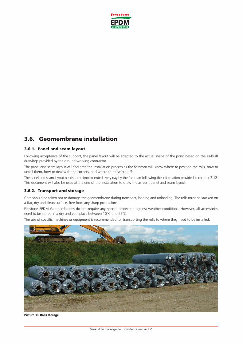
3.6.2. Transport and storage
Care should be taken not to damage the geomembrane during transport, loading and unloading. The rolls must be stacked on
a flat, dry and clean surface, free from any sharp protrusions.
Firestone EPDM Geomembranes do not require any special protection against weather conditions. However, all accessories
need to be stored in a dry and cool place between 10°C and 25°C.
The use of specific machines or equipment is recommended for transporting the rolls to where they need to be installed.
Picture 38: Rolls storage

General technical guide for water reservoirs | 52
3.6.3. Placing the geomembrane
The rolls are unwound and unfolded according to the layout plan. Installation starts with covering the embankments.
The geomembrane panels are unrolled from the trench towards the embankment and the geomembrane is temporarily fixed/
ballasted to avoid it slipping down. Ensure that no pebbles or sharp objects are trapped under the geomembrane, whilst the
sheets are being unrolled. Be sure that nobody is standing downward of the roll before letting it go onto the slope.
If the panel needs to be moved after unfolding, the geomembrane can be lifted at the edge allowing air to play underneath,
thus moving the membrane on an air cushion.
The geomembrane must be installed with some slack to allow for some shrinkage (continuation of the membrane vulcanization)
and dimensional variations due to temperature changes and prevent overstretching in case of differential settlement. However,
it should not be installed leaving excessive wrinkles or creases, especially not in seaming areas.
Excess membrane must be left at the foot of the embankment for connecting with adjoining panels. Horizontal splices on the
embankments must be avoided.
In the corners, the membrane will be either folded or cut. The folds will be fixed with Firestone QuickPrime Plus. It is recommended
to cover the folds with QuickSeam Batten Cover strips or QuickSeam SA Flashing.
Firestone EPDM Geomembranes must relax for at least 30-45 minutes before attachment, cutting or splicing the seams or
executing details. Straight cuts are very important for a neat and easy application. Firestone recommends the use of scissors,
markers and chalklines to achieve this. Do not use cutters.
While installing the sheets, folds in the geotextile and damage to the supporting surface must be avoided.
It is not recommended that EPDM geomembrane sheets are installed when there are heavy winds.
Machines are not allowed to circulate on top of the installed membrane unless it has been specially protected.
Picture 39: Unrolling, unfolding
Picture 40: Moving the geomembrane on air cushion

General technical guide for water reservoirs | 53
3.6.4. Temporary ballast
Directly after unfolding the geomembrane, some temporary ballast needs to be installed in the anchor trench and on
the geomembrane in order to avoid the geomembrane slipping down the slope or being lifted by the wind.
When different panels are seamed together, the wind can enter under the geomembrane and move large quantities of seamed
panels. It is then impossible to replace the panels without making some cuts. Great care therefore needs to be taken at the end
of every working day to make sure that the installed panels are properly ballasted.
Temporary ballasting can be done with sand bags (connected or not by ropes) or any other non-abrasive material such as
rubber tires, etc.
Picture 41: Temporary ballast of the geotextile and the geomembrane with sand bags
3.6.5. Seaming adjoining geomembrane panels
The splicing of adjoining panels should be performed immediately after the relaxation of the Firestone EPDM Geomembrane.
All panels must be installed without tension and without major wrinkles in the seam area, overlapping by at least 150 mm. All
seams on slopes must run up and down the slope with no horizontal seams allowed.
Seaming procedure
Two overlapping Firestone EPDM Geomembrane panels are assembled by means of 76 mm (3”) wide self-adhesive tape,
QuickSeam Splice Tape. Below are the various steps required for correct splicing.
Step 1: Position, fold back the lap edge and temporary bond adjacent panels
Position the sheets at the splice area with an overlap of ± 200 mm (min. 150 mm). The geomembranes must lay flat and
without any tension. The upper geomembrane panel is then folded back ± 200 mm (min. 150 mm). A line of primer (scrubber
width) will be applied simultaneously on the two panels along the entire inside length of the joint. The upper panel is released
and contact is made between the 2 panels by walking on the primed zone.
Temporary bonding the 2 panels will secure their position during the entire seaming process and avoid any dust coming from
the substrate into the seaming zone.
Figure 25: Seaming – Fold back and temporary bond

General technical guide for water reservoirs | 54
Step 2: Mark the sheets
Once both membranes are in place, mark the bottom sheet 10 to 20 mm from the edge of the seam every 300 mm with the
white crayon provided.
Use an index finger as a guide along the top edge; this gives an accurate measurement for this step. The marks will serve as a
guide for the application of the QuickPrime Plus and installation of the QuickSeam Splice Tape.
Figure 26: Seaming – Position and mark of the panels
Step 3: Tack-back the overlap
Tack the top sheet back with QuickPrime Plus at 3.0 m centres and at factory seams. This holds the fold in place during the
splicing operation.
Figure 27: Seaming – Tack-back the overlap
Step 4: Apply QuickPrime Plus
Remove excess dust and dirt on the sheet and at factory seams, using a stiff broom. Pre-scrubbing is required at all areas that
have excess amounts of dust, mica and at all factory seams. Dip the Quick Scrubber Pad into the QuickPrime Plus, keeping the
scrubber horizontal and flat so that no primer drips out prematurely.
Apply the QuickPrime Plus using long back and forth scrubbing strokes, parallel to the seam along the length of the splicing
area, until the surface becomes dark grey in color with no streaking or puddling. Scrub both surfaces at the same time to allow
the same time to go off, start on the folded overlap. Be sure to overlap the guide marks on the bottom sheet and go beyond
the edge of the top sheet.
Figure 28: Seaming – QuickPrime Plus application

General technical guide for water reservoirs | 55
Step 5: Check QuickPrime Plus for dryness
Allow the QuickPrime Plus to go off completely. To test for dryness, use the touch-push test by pushing straight down onto the
QuickPrime Plus with a clean, dry finger. Push forward on the primer at an angle. The primer should feel tacky but not stringy
to the finger.
Figure 29: Seaming – Check for dryness of QuickPrime Plus
Step 6: Install 76 mm (3”) Splice Tape
Position the 76 mm (3”) Splice Tape on the bottom sheet with the release paper facing upwards. Align the edge of the release
paper with the marks. Roll the tape immediately using a 50 mm wide silicone rubber hand roller, applying firm pressure across
the tape to remove any air that may be trapped between primer and tape. Hand pressure is not sufficient to seal the seam, since
it does not provide uniform compression.
Figure 30: Seaming – Splice Tape installation
Step 7: Check tape alignment
Untack the top sheet and allow it to fall freely onto the tape. Trim the top sheet back at all areas where the tape does not extend
5 to 15 mm (maximum 22 mm) outside the seam edge.
Figure 31: Seaming – Check tape alignment
General technical guide for water reservoirs | 56
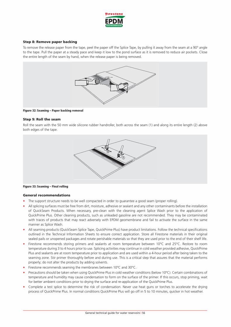
Step 8: Remove paper backing
To remove the release paper from the tape, peel the paper off the Splice Tape, by pulling it away from the seam at a 90° angle
to the tape. Pull the paper at a steady pace and keep it low to the pond surface as it is removed to reduce air pockets. Close
the entire length of the seam by hand, when the release paper is being removed.
Figure 32: Seaming – Paper backing removal
Step 9: Roll the seam
Roll the seam with the 50 mm wide silicone rubber handroller, both across the seam (1) and along its entire length (2) above
both edges of the tape.
Figure 33: Seaming – Final rolling
General recommendations
• The support structure needs to be well compacted in order to guarantee a good seam (proper rolling).
• All splicing surfaces must be free from dirt, moisture, adhesive or sealant and any other contaminants before the installation
of QuickSeam Products. When necessary, pre-clean with the cleaning agent Splice Wash prior to the application of
QuickPrime Plus. Other cleaning products, such as unleaded gasoline are not recommended. They may be contaminated
with traces of products that may react adversely with EPDM geomembrane and fail to activate the surface in the same
manner as Splice Wash.
• All seaming products (QuickSeam Splice Tape, QuickPrime Plus) have product limitations. Follow the technical specifications
outlined in the Technical Information Sheets to ensure correct application. Store all Firestone materials in their original
sealed pails or unopened packages and rotate perishable materials so that they are used prior to the end of their shelf life.
• Firestone recommends storing primers and sealants at room temperature between 10°C and 25°C. Restore to room
temperature during 3 to 4 hours prior to use. Splicing activities may continue in cold weather provided adhesive, QuickPrime
Plus and sealants are at room temperature prior to application and are used within a 4-hour period after being taken to the
seaming zone. Stir primer thoroughly before and during use. This is a critical step that assures that the material performs
properly; do not alter the products by adding solvents.
• Firestone recommends seaming the membranes between 10ºC and 30°C.
• Precautions should be taken when using QuickPrime Plus in cold weather conditions (below 10ºC). Certain combinations of
temperature and humidity may cause condensation to form on the surface of the primer. If this occurs, stop priming, wait
for better ambient conditions prior to drying the surface and re-application of the QuickPrime Plus.
• Complete a test splice to determine the risk of condensation. Never use heat guns or torches to accelerate the drying
process of QuickPrime Plus. In normal conditions QuickPrime Plus will go off in 5 to 10 minutes, quicker in hot weather.

General technical guide for water reservoirs | 57
• In hot weather Firestone recommends applying QuickPrime Plus first onto the bottom sheet and then installing the tape.
After the tape has been rolled, apply QuickPrime Plus to the top sheet. Extreme warm weather may dry out the solvents
quickly. This can be avoided by protecting the primer pails against hot temperatures by installing an insulation board
between the can and membrane on hot summer days and by keeping the pails out of direct sunlight.
• Before using the QuickPrime Plus, ensure that it is thoroughly stirred and poured into a small bucket.
• Assemble the QuickScrubber Pad by twist-locking it into the Scrubber handle. Scrubber pads will last for approximately
60 lm of seam. Replace with a new pad when the pad becomes compressed or when it has dried primer on it. Change the
pad at the start of each working day.
• In normal application, three strokes are typical. The first stroke is to spread the QuickPrime Plus and scrub the membrane;
second stroke is to scrub the membrane and penetrate the primer, the third stroke is to eliminate puddles of QuickPrime
Plus.
• Pre-scrubbing the areas with excess dirt will help the priming process. Three to five strokes with the QuickScrubber,
perpendicular to the seam edge is necessary.
• During the positioning of the tape on the bottom sheet, misalignment may occur. Stop the operation, cut the Splice Tape,
make an overlap of minimum 25 mm with the end of the installed tape and continue the alignment with the markings.
Mark the area for future reference (installation of reinforcement patch). Cutting the tape should be done with the tape
sandwiched between 2 pieces of release paper for a clean cut.
• Any “fish mouth” gap that occurs during installation of the tape should be cut away and repaired with a piece of
QuickSeam FormFlash, covering the perimeters of the cut by minimum 75 mm in all directions.
• After closing the seam, it is important to observe a continuous mark of primer beyond the fold line of the top sheet.
• Moving the Firestone EPDM Geomembrane during application of the Splice Tape and during the first few minutes after
application should be avoided.
• Positioning of a larger number of panels than can be spliced in one day is not allowed.
• Field seams on side slopes must run parallel with the slope i.e. up and down the slope. Horizontal field seams on slopes are
not permitted.
Special considerations
End of Splice Tape
The adjoining roll of tape must overlap a minimum of 25 mm. At these areas a patch of QuickSeam FormFlash should be
installed as illustrated. Apply Lap Sealant around all exposed edges of the QuickSeam FormFlash.
Figure 34: End of splice tape
T-joints
There are two types of T-joints possible, depending whether the transversal joint covers the longitudinal or vice versa. In both
cases, a QuickSeam FormFlash patch is necessary to the dimensions as illustrated below.
When the transversal seam lies on top, trim the QuickSeam Splice Tape so that the edge of the tape and the edge of the EPDM
membrane are flush. Cut away any excess EPDM membrane at the inside of the seam at a 45º angle. Install a QuickSeam patch
over the T-joint area as illustrated below. Seal all exposed edges of the covering piece with Lap Sealant.

General technical guide for water reservoirs | 58
Figure 35: T-joint – Transversal seam lies on top

General technical guide for water reservoirs | 59
Figure 36: T-joint – Longitudinal seam lies on top

General technical guide for water reservoirs | 60
Vertical splice reinforcement
In the area where a field splice runs from the horizontal area into any slope of the embankments the installation of a joint cover
piece at the base is required. The joint cover piece of a minimum 150 by 150 mm will be centered over the seam edge.
min. 75
min
. 150
min.75
min.75
Figure 37: Vertical splice reinforcement
3.6.6. Tool list
Job preparation
• Tape measure (50 m and 5 m)
• Chalk line
• Scissors
• Claw hammer
• Stiff bristle brooms
• Squeegee
Cleaning EPDM geomembrane
• Clean Cotton Rags
• Cleaning Agent – Firestone Splice Wash
Mechanical fixation
• Drilling machine with key
• Drill bits (masonry and steel)
• Hack-saw with blades
• Screw-driver
• Mastic gun
• Tin snip
Installation details
• Quickscrubber pad + handle
• Small plastic bucket
• Marker (white)
• Roller – 50 mm width (silicone rubber)
• Brushes (solvent resistant, short hair and 100 mm width)
• Paint rollers (solvent resistant, short hair and 225 mm width)
• Hot air gun
Additional tools
• Electrical leads
• Rubber gloves
• Tool box with lock
• Mixer
• Cutter
• Insulated storage box
• Temporary ballast
• Safety tools

General technical guide for water reservoirs | 61
3.8. Weather conditions
EPDM geomembranes have been applied at temperatures as low as -40°C and as high as +50°C without the use of any special
equipment. However, at extreme temperatures, there are a couple of points to consider in order to achieve a quality installation.
• EPDM geomembrane panels usually relax within 30 minutes of placement. Colder weather extends this waiting time. EPDM
geomembrane will remain flexible up to -45°C and colder.
• The temperature of EPDM geomembrane can rise up to 80°C when exposed to the sun. It is recommended to wear gloves
when handling the geomembrane and wear knee protection when waterproofing seams and detail work.
• Placement of EPDM geomembrane must not be performed during any form of precipitation (rain, snow, hail), heavy wind,
fog and/or in the presence of any surface moisture or in an area of standing water.
• Installation and positioning of large EPDM geomembrane panels may be difficult in windy conditions. Prevent any wind
from getting under the geomembrane during installation. Use temporary ballast to keep the geomembrane in place until
finally secured to the substrate.
• Precautions should be taken when using Firestone QuickPrime Plus, adhesives and sealants in cold weather conditions
(below 10°C):
- Start working with QuickPrime Plus, sealants and adhesives at room temperature (15-25°C). The use of insulated, heated boxes may be advantageous.
- Cold weather will extend the drying time of QuickPrime Plus and adhesives, since the solvents will take longer to evaporate.
- Seaming a geomembrane at temperatures between +5°C to -7°C is going to require special attention, whereas seaming at temperatures below -7°C is considered to be very difficult. However, the temperature mentioned is the temperature of the geomembrane, which is influenced by the sun (significant warming) and wind (wind chill factor). Preheating the EPDM geomembrane in the seaming area might – in some extreme conditions of cold and wind – be necessary to reduce drying time and make seaming possible.
• When using Firestone QuickPrime Plus in warm weather conditions (> 25°C) the following changes should be made to the
installation technique:
- Do not store the QuickPrime Plus directly onto the heated geomembrane but insulate the product from the geomembrane.
- Do not leave primer cans open as the solvents will evaporate quickly.
- As temperature increases, the drying time of the QuickPrime Plus is reduced. In order not to exceed the open time (time during which the primer remains active) shorten the length of the seaming section to 10 lm. Alternatively the primer can be applied to top and bottom side of the geomembrane separately, starting with the lower membrane. Apply the QuickSeam Splice Tape before priming the top membrane.
• Certain combinations of temperature and humidity may cause water condensation to form on an area of drying primer
or adhesive. The actual appearance of condensation is somewhat unpredictable and its occurrence should continuously
be monitored as work progresses. To determine if condensation has occurred, the following test can be performed.
Approximately five minutes after the primer or adhesive is applied, touch the surface with a clean dry finger. If the primer
or adhesive is tacky to touch, there is no condensation. If the primer or adhesive is coated with a film of moisture, it will not
stick to the finger. If this condition occurs, seaming work must stop until the ambient air conditions no longer cause water
condensation after which a thin additional layer of primer or adhesive needs to be applied.
• Do never use open flame sources (propane torches, etc.) to expedite drying of the primer, adhesives, sealants, etc. Air-dry only.

General technical guide for water reservoirs | 62
3.10. Details
If possible, avoid cutting the Firestone EPDM Geomembrane at details. In some cases, however, as with corner details against
concrete walls and connections to pipes, a cut in the geomembrane will simplify the installation. In such cases, QuickSeam
FormFlash (unvulcanized rubber sheet) will be used in order to provide a watertight seal of the detail.
3.10.1. Corners
Inside corner using 229 mm (9”) QuickSeam FormFlash
Applicability
When flashing onto a concrete structure, the EPDM membrane is cut at the corners so that a vertical seam can be made at the
angle change. The vertical seam is completed with 76 mm (3”) QuickSeam Splice Tape in accordance with general seaming
techniques.
Installation instructions
The inside corner detail is a two step process using two identical pieces of QuickSeam FormFlash to cover the pinhole in the
corner. Apply QuickPrime Plus on the membrane, to an area covering 150 mm from the pinhole on the horizontal and 250 mm
on the vertical surface. In case the hole is larger than a pinhole one should install first a piece of SA Flashing.

General technical guide for water reservoirs | 63
Both pieces of QuickSeam FormFlash are 229 mm wide and 300 mm long. Make sure to round all corners of the cut QuickSeam
FormFlash pieces. Allow the QuickPrime Plus to go off completely before closing the QuickSeam FormFlash.
Fold the first QuickSeam FormFlash piece back on itself lengthwise, making sure the fold is approximately 10 mm offset from
the center of the piece. Fold back a square base on the smaller half and remove the release paper.
Position the folded base on the horizontal surface, 10 mm out from the upstand, as illustrated. Work the flashing piece tightly
into the angle change and continue up against the upstand opposite to the vertical seam.
Work the QuickSeam FormFlash piece into the two remaining angle changes, forming a pig ear as illustrated. Beginning at the
base, press the piece onto the vertical wall to form the pig ear fold. Work from the base of the fold to remove any entrapped
air. Roll the QuickSeam FormFlash gently with a silicone rubber roller.
Apply QuickPrime Plus to the area that will be covered by the pig ear as illustrated and adhere the pig ear on the side of the
vertical seam. Roll all adhered parts of the QuickSeam FormFlash piece with a small 50 mm wide silicone roller.
Use the second piece of QuickSeam FormFlash to cover the pig ear fold after reapplying QuickPrime Plus to the designated
area. Be sure to center the width of the second piece over the side edge of the first piece and work it completely into the angle
change. Roll the entire flashing piece with a silicone roller. Seal all exposed edges with Lap Sealant.

General technical guide for water reservoirs | 64
Outside corner using 229 mm (9”) QuickSeam FormFlash
At outside corners, the EPDM flashing can be continuous (wrap piece on smaller penetrations), or in separate flashing pieces
that are spliced together with a vertical seam at the corner. In both cases, the pinhole at the bottom of the outside corner will
be waterproofed using a square piece of QuickSeam FormFlash of 229 mm wide that is cut circular at one end. Round off the
cut corners on the opposite side.
After completion of the vertical seam at the corner (if required), clean the corner area with QuickPrime Plus as illustrated. Fold
the QuickSeam FormFlash piece in half with the release paper on the outside. Remove the paper from the square half.
Position the flashing piece with the center aligned at the corner. Wrap both sections around the corner and close them to the
vertical upstand.
Remove the second half of the release paper and work the QuickSeam FormFlash from the tape side down to the angle change,
as illustrated. Work the piece into the angle and continue out approximately 20 mm onto the horizontal surface, without
overstretching. The diamond pattern into the material should remain visible. Fold the remainder of the circular part onto the
horizontal surface, taking care to evenly distribute the stresses.
General technical guide for water reservoirs | 65
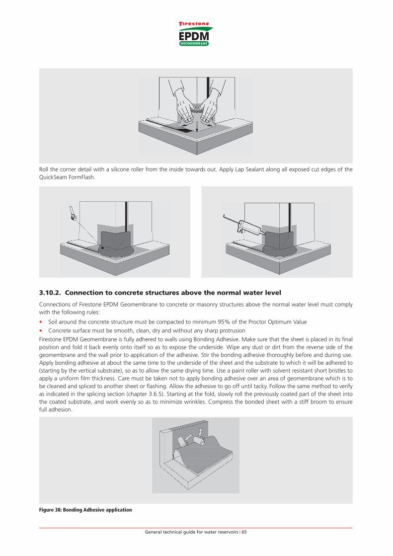
Roll the corner detail with a silicone roller from the inside towards out. Apply Lap Sealant along all exposed cut edges of the
QuickSeam FormFlash.
3.10.2. Connection to concrete structures above the normal water level
Connections of Firestone EPDM Geomembrane to concrete or masonry structures above the normal water level must comply
with the following rules:
• Soil around the concrete structure must be compacted to minimum 95% of the Proctor Optimum Value
• Concrete surface must be smooth, clean, dry and without any sharp protrusion
Firestone EPDM Geomembrane is fully adhered to walls using Bonding Adhesive. Make sure that the sheet is placed in its final
position and fold it back evenly onto itself so as to expose the underside. Wipe any dust or dirt from the reverse side of the
geomembrane and the wall prior to application of the adhesive. Stir the bonding adhesive thoroughly before and during use.
Apply bonding adhesive at about the same time to the underside of the sheet and the substrate to which it will be adhered to
(starting by the vertical substrate), so as to allow the same drying time. Use a paint roller with solvent resistant short bristles to
apply a uniform film thickness. Care must be taken not to apply bonding adhesive over an area of geomembrane which is to
be cleaned and spliced to another sheet or flashing. Allow the adhesive to go off until tacky. Follow the same method to verify
as indicated in the splicing section (chapter 3.6.5). Starting at the fold, slowly roll the previously coated part of the sheet into
the coated substrate, and work evenly so as to minimize wrinkles. Compress the bonded sheet with a stiff broom to ensure
full adhesion.
Figure 38: Bonding Adhesive application

General technical guide for water reservoirs | 66
Adjoining wall flashings are overlapped using standard seaming techniques. At the base, install a vertical splice reinforcement
of minimum 150 by 225 mm centered over the seam edge as illustrated in Figure 37.
The Firestone EPDM Geomembrane is fixed at the top (above the waterline) using a termination bar. Keep a minimum space of
5 mm between two adjoining bars. The termination bar must be installed directly onto the wall surface. Pre-drill holes into the
brick, masonry or concrete but not into the soft mortar joint. A termination bar must be cut at inside and outside corners. Do
not bend the bar around the corners. Prior to installation of the termination bar, pull back the topside of the membrane flashing
20 mm and apply a bead of Water Block between the membrane and the wall.
Install the termination bar with an acceptable hammer plug system at 150 mm o.c. Continuous compression is required and
if needed additional fastening must be installed. Each termination bar must be fastened a maximum of 25 mm from the end.
Apply a bead of Lap Sealant or an acceptable High Grade Sealant on the topside of the bar.
Figure 39: Connection to concrete structures above the normal water level
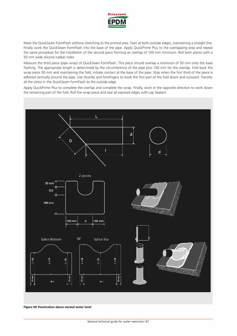
3.10.3. Penetrations above the normal water level
Connections to penetrations above the normal water level or under low water pressure (less than 2.0 m water pressure) can be
made by means of unvulcanized rubber sheet, QuickSeam FormFlash, as follows:
• Pipe needs to be firmly anchored and the pipe temperature may not exceed 80°C.
• Make a circular cut in the geomembrane panel, measuring approximately 50% of the pipe diameter. Pull the geomembrane
over the pipe.
• Pipe and geomembrane are flashed together by means of a piece of QuickSeam FormFlash and QuickSeam SA Flashing
whenever possible.
• Finally, the assembly is mechanically secured with a stainless steel clamping collar (with a protection strip).
This technique cannot be used for multiple penetrations, flexible conduits and cables.
If the geomembrane has been cut to accommodate the penetration, repair the cut as per Firestone specifications before
installing the pipe flashing.
The area around the cut in the geomembrane needs to be reinforced. This will be done with a piece of QuickSeam SA Flashing
whenever possible or two pieces of QuickSeam FormFlash.
Base flashing using SA Flashing
Cut a piece of SA Flashing that will overlap a minimum of 100 mm in all directions onto the geomembrane and cut a hole
20 mm smaller in size than the base of the pipe (D x d in Figure 40). Apply QuickPrime Plus on the designated area on the
geomembrane and the pipe. Allow the primer to flash off and apply the piece of SA Flashing.
QuickSeam FormFlash application:
The base flashing of the pipe consists of two identical pieces of QuickSeam FormFlash.
The dimensions of the QuickSeam FormFlash pieces are such that a base overlap of 100 mm with the field membrane in
all directions and a 100 mm overlap between the two FormFlash pieces is provided. This results in an overall dimension of
(200 + Ø) x (100 + 50+Ø/2). Pipes larger than 225 mm in diameter require the use of one or two EPDM base pieces, applied
with normal seaming techniques.
Apply QuickPrime Plus to the pipe and the base membrane around the pipe in the designated area. Allow the QuickPrime Plus
to go off completely. Apply the first piece of QuickSeam FormFlash and roll it towards the pipe, mark the diameter of the pipe
on the reverse side of the QuickSeam FormFlash and make a horseshoe shape cut ensuring a 25 mm overlap up the pipe.
General technical guide for water reservoirs | 67
Mate the QuickSeam FormFlash without stretching to the primed area. Start at both outside edges, maintaining a straight line.
Finally work the QuickSeam FormFlash into the base of the pipe. Apply QuickPrime Plus to the overlapping area and repeat
the same procedure for the installation of the second piece forming an overlap of 100 mm minimum. Roll both pieces with a
50 mm wide silicone rubber roller.
Measure the third piece (pipe wrap) of QuickSeam FormFlash. This piece should overlap a minimum of 50 mm onto the base
flashing. The appropriate length is determined by the circumference of the pipe plus 100 mm for the overlap. Fold back the
wrap piece 50 mm and maintaining the fold, initiate contact at the base of the pipe. Stop when the first third of the piece is
adhered vertically around the pipe. Use thumbs and forefingers to work the first part of the fold down and outward. Transfer
all the stress in the QuickSeam FormFlash to the outside edge.
Apply QuickPrime Plus to complete the overlap and complete the wrap. Finally, work in the opposite direction to work down
the remaining part of the fold. Roll the wrap piece and seal all exposed edges with Lap Sealant.
Figure 40: Penetration above normal water level
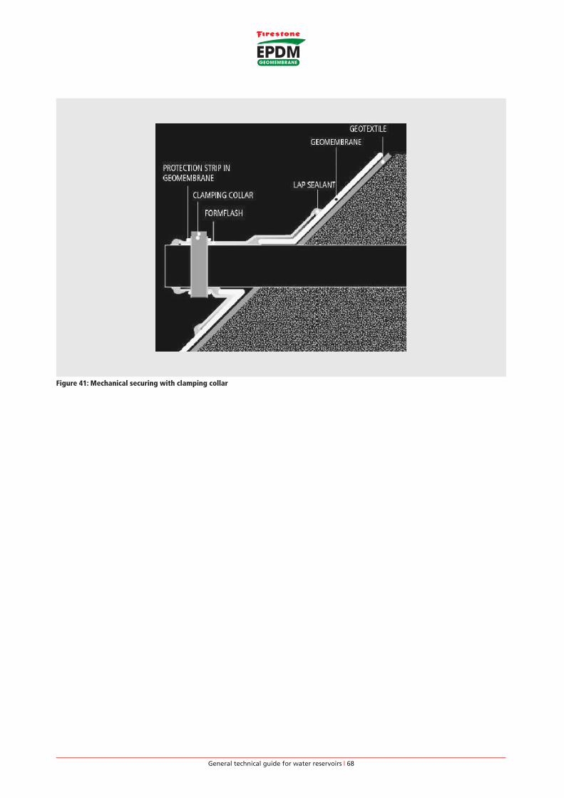
General technical guide for water reservoirs | 68
Figure 41: Mechanical securing with clamping collar

General technical guide for water reservoirs | 69
3.10.4. Connection to concrete structures located below normal water level
Mechanical anchoring of the geomembrane to concrete structures needs to be executed with the utmost care.
There are several ways of realizing this detail. Some solutions are presented below but they need to be adapted to the specifics
of each site (water pressure, concrete quality).
In any case, the following recommendations should be followed:
• Very good ground compaction near the concrete structure (minimum 95% of the Proctor Optimum Value).
• Concrete slab must be smooth, flat and resistant.
• The anchoring metal bar needs to be rigid and the distance between fasteners properly designed in order to apply a
constant pressure over the entire surface.
• The geomembrane has to be glued to the concrete structure over minimum 100 mm starting from the mechanical anchoring.
For vertical connections, it is recommended to glue the geomembrane onto the entire vertical surface.
• Double or triple the protective geotextile at the junction between the ground and the concrete. The geotextile needs to be
glued to the concrete slab.
Figure 42: Mechanical attachment below water line
General technical guide for water reservoirs | 70
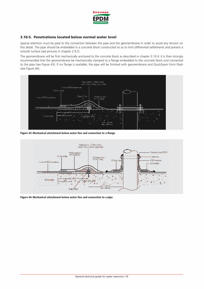
3.10.5. Penetrations located below normal water level
Special attention must be paid to the connection between the pipe and the geomembrane in order to avoid any tension on
this detail. The pipe should be embedded in a concrete block constructed so as to limit differential settlements and present a
smooth surface (see pictures in chapter 2.9.2).
The geomembrane will be first mechanically anchored to the concrete block as described in chapter 3.10.4. It is then strongly
recommended that the geomembrane be mechanically clamped to a flange embedded to the concrete block and connected
to the pipe (see Figure 43). If no flange is available, the pipe will be finished with geomembrane and QuickSeam Form Flash
(see Figure 44).
Figure 43: Mechanical attachment below water line and connection to a flange
Figure 44: Mechanical attachment below water line and connection to a pipe