general specifications analog i/o modules (for...
TRANSCRIPT

GeneralSpecifications
<<Contents>> <<Index>>
Analog I/O Modules (for FIO)
Yokogawa Electric Corporation2-9-32, Nakacho, Musashino-shi, Tokyo, 180-8750 JapanTel.: 81-422-52-5634 Fax.: 81-422-52-9802
GS 33K50F60-50E
GS 33K50F60-50E©Copyright Aug. 2011(YK)
4th Edition Dec. 1, 2013(YK)
GENERALThis document describes about hardware specifications of Analog I/O Modules (for FIO) to be installed in the ESB bus node units (ANB10S and ANB10D), Optical ESB bus node units (ANB11S and ANB11D), ER bus node units (ANR10S and ANR10D) (*1), and field control units (for FIO) (AFV30S, AFV30D, AFV40S, AFV40D, AFV10S, AFV10D, AFF50S, and AFF50D).These analog I/O modules function as signal converters; by inputting field analog signals into these modules, it converts them to internal data for field control stations (FCS), or the FCS’s internal data to analog signals for outputs.
*1: Field control units (AFV30 and AFV40) do not support ER bus node unit (ANR10).

2
All Rights Reserved. Copyright © 2011, Yokogawa Electric Corporation
<<Contents>> <<Index>>
GS 33K50F60-50E
STANDARD SPECIFICATIONS Current/Voltage Input Modules (Non-Isolated)These modules provide 16 inputs of mainly 4 to 20 mA DC or 1 to 5 V DC standardized signals from 2-wire/4-wire transmitters.They can be used in dual-redundant configuration.
Items SpecificationsModel AAI141 (*1) AAV141 AAV142 AAB141(*1) (*4)
Number of input channels 16, non-isolated 16, non-isolated (differential input) 16, non-isolated
16, non-isolated When the voltage input is selected the differential input is applied.
Input signal 4 to 20 mA DC 1 to 5 V DC (allowable common mode voltage ± 1 V or less)
-10 to 10 V DCVoltage input : 1to 5 V DC (allowable common mode voltage ±1 V or less)Current input : 4 to 20 mA DC(*5)
Allowable input current/voltage 27 mA ±7.5 V ±13 V Voltage input : ±7.5 VCurrent input : 25 mA
Withstanding voltage —
Input resistancePower ON 400 Ω (at 20 mA) to
1000 Ω (at 4 mA) (*2) 1 MΩ or larger 1 MΩ or largerVoltage input : 1 MΩ or largerCurrent input : 290 Ω (at 20 mA) to 450 Ω (at 4 mA) (*6)
Power OFF 500 kΩ or larger 340 kΩ or larger 660 kΩ or larger Voltage input : 340 kΩ or largerCurrent input : 500 kΩ or larger
Accuracy ±16 µA ±4 mV ±20 mV Voltage input : ±4 mVCurrent input : ±16 μA
Data update period 10 msStep response time 100 ms
Transmitter power supply14.8 V or higher(at 20 mA) (*3) 26.4 V or less (at 0 mA) (output current limit: 27 mA)
—
Setting of 2-wire or 4-wire transmitter
For each channel by setting pin —
Drift due to ambient temperature change ±16 µA/10 °C ±4 mV/10 °C ±20 mV/10 °C ±0.1 %/10 °C
Maximum current consumption
310 mA (5 V DC), 450 mA (24 V DC) 350 mA (5 V DC) 350 mA (5 V DC) 480 mA (5 V DC),
120 mA (24 V DC)Weight 0.2 kg 0.2 kg 0.2 kg 0.3 kgExternal connection Pressure clamp terminal, KS cable, MIL connector cable KS cableHART communication (*7) Available — — Available (at current input)
*1: A Zener barrier is not allowed to be connected with this module. Use an isolation barrier when the module is used in intrinsically safe application.
*2: The module input resistance viewed from the terminals depends on the current strength as calculated as below:
250 Ω +current value
voltage drop in the input protection circuit
F01E.ai
*3: This voltage is generated between the connecting terminals for 2-wire transmitters for this module. When calculating the minimum operating voltage for transmitters, consider to allow margins for voltage drop in external wiring.
*4: This module can be used only with the following FCSs – AFG30, AFG40, AFG8, AFF50, AFV10, AFV30, or AFV40.
*5: Input mode for each channel is selectable by software.*6: The module input resistance viewed from the terminals depends on the current strength as calculated as below:
250 Ω +current value
voltage drop in the input protection circuit
F02E.ai
*7: When this module is installed to a ER bus node unit with HART function, the EB401 firmware must be rev. 2 or later.
June 1, 2012-00

3<<Contents>> <<Index>>
All Rights Reserved. Copyright © 2011, Yokogawa Electric Corporation GS 33K50F60-50E
Current/Voltage I/O Modules (Non-Isolated)These modules provide 8 inputs and 8 outputs to support up to 8 loops. They can be used in dual-redundant configuration.
Items Specifications Model AAI841 (*1) AAB841 (*5) AAB842 (*5) (*6)
Number of I/O channels 8-channel input/8-channel output, non-isolated
8-channel input/8-channel output, non-isolated (differential input)
8-channel input/8-channel output, non-isolatedWhen the voltage input is selected the differential input is applied.
I/O signal Input: 4 to 20 mA
Output: 4 to 20 mA
Input: 1 to 5 V (allowable common mode voltage ±1 V or less)
Output: 4 to 20 mA
Input (*7)Voltage input: 1 to 5 V DC (allowable common mode voltage ±1 V or less)Current input:4 to 20 mA DC
Output:4 to 20 mA
Allowable input current/voltage 25 mA — ±7.5 V —
Voltage input : ±7.5 VCurrent input : 25 mA
—
Withstanding voltage —
Input resistance
Power ON
400 Ω (at 20 mA) to 1000 Ω (at 4 mA) (*2)
— 1 MΩ or larger —
Voltage input: 1 MΩ or largerCurrent input: 290 Ω (at 20 mA) to 450 Ω (at 4 mA) (*2)
—
Power OFF 500 kΩ or larger — 340 kΩ or larger —
Voltage input: 340 kΩ or largerCurrent input: 500 kΩ or larger
—
Allowable load resistance — 0 to 750 Ω (*3) — 0 to 750 Ω — 0 to 750 Ω (*4)
Circuit-open detection — Less than 0.65 mA — Less than 0.65
mA — Less than 0.65 mA
Accuracy Input: ±16 µA output: ±48 µA Input: ±4 mV output: ±48 µA Voltage input : ±4 mVCurrent input : ±16 μA
±48 μA
Data update period 10 ms Input step response time 100 ms Output step response time 40 ms
Transmitter power supply 14.8 V or higher (at 20 mA) 26.4 V or less (at 0 mA) (*4) —
Setting of 2-wire or 4-wire transmitter For each channel by setting pin —
Temperature drift ±0.1 %/10 °C Maximum current consumption
310 mA (5 V DC), 500 mA (24 V DC)
310 mA (5 V DC), 250 mA (24 V DC)
410 mA (5 V DC),290 mA (24 V DC)
Weight 0.3 kg External connection Pressure clamp terminal, KS cable, MIL connector cable KS cable
HART communication (*8) Available — Available (at Current input and output)
*1: A Zener barrier is not allowed to be connected with this module. Use an isolation barrier when the module is used in intrinsically safe application.
*2: The module input resistance viewed from the terminals depends on the current strength as calculated as below:
250 Ω +current value
voltage drop in the input protection circuit
F03E.ai
*3: When this module is used in the ambient temperature of 60 to 70 ºC by being installed in a node unit that conforms to the temperature environment, the allowable load resistance is 200 to 750 Ω.
*4: This voltage is generated between the connecting terminals for 2-wire transmitters for this module. When calculating the minimum operating voltage for transmitters, consider to allow margins for voltage drop in external wiring.
*5: A Zener barrier is not allowed to be connected with this module for current output. Use an isolation barrier when the module is used in intrinsically safe application.
*6: A Zener barrier is not allowed to be connected with this module for current input. Use an isolation barrier when the module is used in intrinsically safe application. And this module can be used only with the following FCSs – AFG30, AFG40, AFG8, AFF50, AFV10, AFV30, or AFV40.
*7: Input mode for each channel is selectable by software.*8: When this module is installed to a ER bus node unit with HART function, the EB401 firmware must be rev. 2 or later.
Dec. 1, 2013-00

4
All Rights Reserved. Copyright © 2011, Yokogawa Electric Corporation
<<Contents>> <<Index>>
GS 33K50F60-50E June 1, 2012-00
Voltage Output Module (Non-Isolated)This module provides 16 outputs of -10 to +10 V DC signal. It can be used in dual-redundant configuration.
Items Specifications Model AAV542
Number of output channels 16, non-isolated Output signal -10 to 10 V Withstanding voltage — Allowable load resistance 10 kΩ or larger Accuracy Larger of ±0.3 %/FS and ±12 mV Data update period 10 ms Output step response time 40 ms Temperature drift Larger of ±0.1 %/10 °C and ±10 mV/10 °C Maximum current consumption 450 mA (5 V DC) Weight 0.2 kg External connection Pressure clamp terminal, KS cable, MIL connector cable
Current Input Modules (Isolated)This module provides 16 inputs of 4 to 20 mA signal. It can be used in dual-redundant configuration.
Items Specifications Model AAI143 (*1)
Number of input channels 16, isolated Input signal 4 to 20 mA Allowable input current 24 mA Withstanding voltage Between input and system: 1500 V AC, for 1 minute (*4)
Input resistance Power ON 270 Ω (20 mA) to 350 Ω (4 mA) (*2) Power OFF 500 kΩ or larger
Accuracy ±16 µA Data update period 10 ms Transmitter power supply 19.0 V or higher (at 20 mA) 25.5 V or less (at 0 mA) (output current limit: 25 mA) (*5) Setting of 2-wire or 4-wire transmitter For each channel by setting pin Drift due to ambient temperature change ±16 µA/10 C Maximum current consumption 230 mA (5 V DC), 540 mA (24 V DC) Weight 0.3 kg External communication Pressure clamp terminal, MIL connector cable, dedicated cable (KS1) HART communication (*3) Available
*1: A Zener barrier is not allowed to be connected with this module. Use an isolation barrier when the module is used in intrinsically safe application.
*2: The module input resistance viewed from the terminals depends on the current strength as calculated as below:
250 Ω +current value
voltage drop in the input protection circuitF04E.ai
*3: When this module is installed to a ER bus node unit with HART function, the EB401 firmware must be rev. 2 or later.*4: When the dedicated cable is used, the withstanding voltage is 500 V AC (between the input signal and the system). When
the ML connector cable is used, the withstanding voltage depends on the electrical specifications of the cable.*5: This voltage is generated between the connecting terminals for 2-wire transmitters for this module. When calculating the
minimum operating voltage for transmitters, consider to allow margins for voltage drop in external wiring.

5<<Contents>> <<Index>>
All Rights Reserved. Copyright © 2011, Yokogawa Electric Corporation GS 33K50F60-50E Dec. 1, 2013-00
Current Output Module (Isolated)This module provides 16 outputs of 4 – 20 mA signal. It can be used in dual-redundant configuration. (*1)
Items Specifications Model AAI543-5/-E AAI543-6/-F (*2)
Number of output channels 16, isolated, standard switch-over response in redundant configuration (*3)
16, isolated, fast switch-over response in redundant configuration (*3)
Output signal 4 to 20 mA Withstanding voltage Between output and system: 1500 V AC, for 1 minute (*4) Allowable load resistance 0 to 750 Ω Circuit-open detection Less than 0.65 mA Accuracy ±48 µA Data update period 10 ms Drift due to ambient temperature change ±16 µA/10 C Maximum current consumption 230 mA (5 V DC), 540 mA (24 V DC) Weight 0.4 kg External communication Pressure clamp terminal, MIL connector cable, dedicated cable (KS1) HART communication (*5) Available
*1: A dual-redundant configuration is enabled by using two identical modules with the same suffix codes.*2: When AAI543-6/-F is installed in a node unit that conforms to the temperature environment, use it in the ambient
temperature within 0 to 60 ºC range.*3: When a switch over from control to stand-by module takes place in the dual-redundant configuration, the maximum period
of time when the field output falls below 4 mA is 100 ms for AAI543-5/-E (standard switch-over response) and 2 ms for AAI543-6/-F (fast switch-over response). In case of connecting fast response type field devices, use AAI543-6/-F (fast switch-over response) in the dual-redundant configuration.
*4: When the dedicated cable is used, the withstanding voltage is 500 V AC (between the input signal and the system). When the ML connector cable is used, the withstanding voltage depends on the electrical specifications of the cable.
*5: When this module is installed in a ER bus node unit with HART function, the EB401 firmware must be rev. 2 or later.
Voltage Input Module (Isolated)This module is for 16 inputs of 1 to 5 V or -10 to 10 V signal. It can be used in dual-redundant configuration.
Items Specifications Model AAV144
Number of input channels 16, isolated Input signal 1 to 5 V -10 to 10 V Switching input signals Input signals can be set together for CH1 to CH16 Allowable input voltage ±30 V Withstanding isolated voltage Between input and system: 1500 V AC withstanding voltage, for 1 minute (*1)
Input resistance Power ON 1 MΩ Power OFF 200 kΩ
Accuracy ±4 mV ±20 mVData update period 10 ms Drift due to ambient temperature change ±4 mV/10 C ±20 mV/10 CMaximum current consumption 500 mA (5 V DC) Weight 0.2 kg External communication Pressure clamp terminal, MIL connector cable, dedicated cable (KS1)
*1: When the dedicated cable is used, the withstanding voltage is 500 V AC (between the input signal and the system). When the ML connector cable is used, the withstanding voltage depends on the electrical specifications of the cable.

6
All Rights Reserved. Copyright © 2011, Yokogawa Electric Corporation
<<Contents>> <<Index>>
GS 33K50F60-50E Aug. 19, 2011-00
Voltage Output Modules (Isolated)This module is for 16 outputs of -10 to 10V signal. It can be used in dual-redundant configuration.
Items Specifications Model AAV544
Number of output channels 16, isolated Output signal -10 to 10 V Withstanding voltage Between output and system: 1500 V AC withstanding voltage, for 1 minute (*1) Allowable load resistance 5 kΩ or largerAccuracy The larger of ±12 mV or ±0.3 % FS Data update period 10 ms Drift due to ambient temperature change The larger of ±0.1 %/10 C or ±10 mV/10 C Maximum current consumption 860 mA (5 V DC) Weight 0.2 kg External communication Pressure clamp terminal, MIL connector cable, dedicated cable (KS1)
*1: When the dedicated cable is used, the withstanding voltage is 500 V AC (between the input signal and the system). When the ML connector cable is used, the withstanding voltage depends on the electrical specifications of the cable.

7<<Contents>> <<Index>>
All Rights Reserved. Copyright © 2011, Yokogawa Electric Corporation GS 33K50F60-50E Aug. 19, 2011-00
TC/RTD Input Modules (Isolated)These modules receive signals from mV, thermocouple (TC), and RTD. They can be used in dual-redundant configuration.
Items Specifications Model AAT141 AAR181
Number of input channels 16, isolated (*7) 12, isolated
Input signal TC: JIS C1602:1995, IEC584:1995 Type J, K, E, B(*1), R, S, T, N mV: -100 to 150 mV, -20 to 80 mV
RTD: JIS C1604:1997, IEC751:1995 Pt100 (3-wire type)(*6)
Switching input signals TC/mV can be set individually for CH1 to CH16. CH1 to CH12 are RTD inputs. Allowable input voltage ±5 V ±5 V Withstanding voltage Between input and system: 1500 V AC, for 1 minute
Input resistance Power ON 2 MΩ or largerPower OFF 2 MΩ or larger
Accuracy TC: ±30 µV MV: ±80 µV for span (-100 to 150 mV) ±30 µV for span (-20 to 80 mV)
RTD: ±120 mΩ
Allowable total resistance of signal source plus wiring 1000 Ω or less 40 Ω or less (wiring resistance per wire) (*2)
Effect of allowable signal source resistance (1000 Ω) ±20 µV(*3) —
Reference junction compensation accuracy Within ±1 °C (*4) (*5) —
Measurement current — RTD: 1 mA
Temperature drift ±80 µV/10 °C (-100 to 150 mV input) ±30 µV/10 °C (TC/-20 to 80 mV input) ±120 mΩ/10 °C (RTD input)
Data update period 1 s
Burn-out All channels can be set together. Setting: Not available/available (UP/DOWN) Detection time: 60 s
Maximum current consumption 450 mA (5 V DC) 450 mA (5 V DC) Weight 0.2 kg External connection Pressure clamp terminal
*1: Type B does not carry out temperature compensation and temperature under 44 ºC is not measurable.*2: Wiring resistance for the signal cables of INA and INC must be identical.*3: In dual-redundant configuration, it is ±40 μV.*4: This figure varies depending on the installation conditions. When the measured temperature is below 0 ºC, multiply the following coefficient (K) with the above value.
K =Thermoelectromotive force per degree at measured temperature
Thermoelectromotive force per degree at 0 °C
F05E.ai
*5: The reference junction compensation accuracy varies depending on the ambient temperature of the pressure clamp terminal.
By the Node Unit Only
Temperature Environment Reference Junction Compensation Accuracy -20 to 15 C ±2 C 15 to 45 C ±1 C 45 to 70 C ±2 C
Installed in the Standard Cabinet
Temperature Environment Reference Junction Compensation Accuracy 0 to 50 C ±2 C
*6: AAR181 also supports JPt 100.*7: Use a non-ground type thermocouple (TC) because AAT141 is an isolated type module. When the ground type TC is used
with the module’s multiple channels, it causes a temperature error due to the multi-point ground.

8
All Rights Reserved. Copyright © 2011, Yokogawa Electric Corporation
<<Contents>> <<Index>>
GS 33K50F60-50E June 1, 2012-00
Current Input Module and Current I/O Module (Isolated Channels)The current input module receives signal of 4 to 20 mA, and the current I/O module sends and receives signals of 4 to 20 mA. These modules are isolated between the field and the system as well as in between each channel. They can be used in dual-redundant configuration.
Items Specifications Model AAI135 (*1) AAI835 (*1)
Number of I/O channels 8-channel input, isolated channels 4-channel input/4-channel output, isolated channels I/O signal 4 to 20 mA Input: 4 to 20 mA Output: 4 to 20 mA Allowable input current 25 mA 25 mA —
Withstanding voltage Between input and system: 500 V AC, for 1 minute Between input channels: 500 V AC, for 1 minute (*2)
Between input/output and system: 500 V AC, for 1 minute Between input/output channels: 500 V AC, for 1 minute (*2)
Input resistance
Power ON 290 Ω (at 20 mA) to 450 Ω (at 4 mA) (*3) Power OFF 500 kΩ or larger
Allowable load resistance — — 0 to 750 Ω (*4) Circuit-open detection — — Less than 0.65 mA Accuracy ±16 µA Input: ±16 µA Output: ±48 µA Data update period 10 ms
Transmitter power supply 15.0 V or higher (at 20 mA) 29.3 V or less (at 0 mA) (*5)
15.0 V or higher (at 20 mA) 29.3 V or less (at 0 mA) (*5) —
Temperature drift ±16 µA/10 °C Maximum current consumption 360 mA (5 V DC), 450 mA (24 V DC) 360 mA (5 V DC), 450 mA (24 V DC)
Weight 0.3 kg External connection Pressure clamp terminal, MIL connector cable, dedicated cable (KS1) HART communication (*6) Available Available
*1: A Zener barrier is not allowed to be connected with this module. Use an isolation barrier when the module is used in intrinsically safe applications.
*2: When the ML connector cable is used, the withstanding voltage depends on the electrical specifications of the cable.*3: The module input resistance viewed from the terminals depends on the current strength as calculated as below:
250 Ω +current value
voltage drop in the input protection circuit
F06E.ai
*4: When this module is used in the ambient temperature of 60 to 70 ºC by being installed in a ER bus node unit that conforms to the temperature environment, the allowable load resistance is 200 to 750 Ω.
*5: This voltage is generated between the connecting terminals for 2-wire transmitters for this module. When calculating the minimum operating voltage for transmitters, consider to allow margins for voltage drop in external wiring.
*6: When this module is installed to a ER bus node unit with HART function, the EB401 firmware must be rev. 2 or later.

9<<Contents>> <<Index>>
All Rights Reserved. Copyright © 2011, Yokogawa Electric Corporation GS 33K50F60-50E Aug. 19, 2011-00
TC/RTD Input Modules (Isolated Channels)These modules receive signals from mV, thermocouple (TC), RTD, and potentiometer (POT), and they are isolated between the field and the system as well as in between each channel. They can be used in dual-redundant configuration.
Items Specifications Model AAT145 AAR145
Number of input channels 16, isolated channels 16, isolated channels
Input signal TC: JIS C1602:1995 (*1), IEC584:1995 Type J,
K, E, B (*2), R, S, T, N mV: -100 to 150 mV, -20 to 80 mV
RTD: JIS C1604:1997 (*3), IEC751:1995 Pt100 (3-wire type)
POT: Total resistance 100 Ω to 10 kΩ Span resistance: 50 % or larger of total resistance
Switching input signals TC/mV can be set individually for CH1 to CH16. RTD/POT can be selected individually for CH1 to CH16.
Allowable input voltage ±5 V ±5 V
Withstanding voltage Between input and system: 500 V AC (for single card: 1500 V AC), For 1 minute Between input channels: 200 V AC, For 1 minute
Input resistance Power ON 1 MΩ or largerPower OFF 1 MΩ or larger
Accuracy ±40 µV RTD: ±150 mΩ POT: ±0.2 %/FS
Allowable total resistance of signal source plus wiring 1000 Ω or less 150 Ω or less (wiring resistance per wire) (*4)
Effect of allowable signal source resistance (1000 Ω) ±20 µV —
Reference junction compensation accuracy ±1 °C (*5) (6) —
Measurement current — RTD: 1 mA Data update period 1 s
Burn-out All channels can be set together. Setting: not available/available (UP/DOWN) Detection time: 60 s
Temperature drift ±80 µV/10 °C RTD: ±0.3 Ω/10 °C POT: ±0.4 %/10 °C
Maximum current consumption 350 mA (5 V DC) 350 mA (5 V DC)
Weight 0.3 kg External connection Dedicated cable (KS1) Dedicated cable (KS8/AKB335)
*1: AAT145 also complies with JIS C1602:1981.*2: Type B does not carry out temperature compensation and temperature under 44 ºC is not measurable.*3: AAR145 also complies with JIS C1604:1989 (Pt100, JPt100).*4: Wiring resistance for the signal cables of INA and INC must be identical.*5: This figure varies depending on the installation conditions. When the measured temperature is below 0 ºC, multiply the following coefficient (K) with the above value.
K =Thermoelectromotive force per degree at measured temperature
Thermoelectromotive force per degree at 0 °C
F07E.ai
*5: The reference junction compensation accuracy varies depending on the ambient temperature of the terminal board (AET4D).
By the Terminal Board Only
Temperature Environment Reference Junction Compensation Accuracy -20 to 0 C ±1.5 C 0 to 30 C ±1.0 C 30 to 70 C ±1.5 C
Installing in the Standard Cabinet
Temperature Environment Reference Junction Compensation Accuracy 0 to 30 C ±1.0 C 30 to 50 C ±1.5 C

10
All Rights Reserved. Copyright © 2011, Yokogawa Electric Corporation
<<Contents>> <<Index>>
GS 33K50F60-50E Aug. 19, 2011-00
Pulse Input Module (Isolated Channels)This module receives contact ON/OFF, voltage pulse, and current pulse signals. It is isolated between the field and the system as well as in between each channel, and can be used in dual-redundant configuration.
Items Specifications Model AAP135
Number of input channels 8, isolated channels
Input signal (*3) 2-wire type: Contact ON/OFF, voltage pulse, current pulse (possible to supply transmitter power supply) 3-wire type: Power-supply-type voltage pulse
Input frequency 0 to 10 kHz (*4)
Withstanding voltage Between input and system: 500 V AC, for 1 minute Between channels: 500 V AC, for 1 minute (*1)
Minimum input pulse width 40 µs
Input signal level
Contact input Open/close levels of relay contact and transistor contact Open: 100 kΩ or larger, Close: 200 Ω or less Contact capacity When supplying 12 V DC: 15 V DC 15 mA or higherWhen supplying 24 V DC: 30 V DC 30 mA or higher
Voltage/current pulse input (Current input is converted to voltage.) VH (high level): 3 to 24 V DC VL (low level): -1 to 8 V DC VH-VL (swing value): 3 V or higherSignal source resistance: 1 kΩ or less
Shunt resistance Can be selected from none/200/500/1000 Ω. (Open when power is OFF and for the standby side in a dual-redundant configuration)
Pull-up resistance 68 kΩ (12 V DC or 24 V DC) Filter Filter for eliminating chattering can be set. (*2) Data update period 2 ms
Transmitter power supply Can select 24 V DC/12 V DC. Limiter value 12 V DC ±10 %: 40 mA, 24 V DC ±10 %: 30 mA
Maximum current consumption 300 mA (5 V DC), 400 mA (24 V DC) Weight 0.3 kg External connection Pressure clamp terminal, KS cable, MIL connector cable
*1: When the ML connector cable is used, the withstanding voltage depends on the electrical specifications of the cable.*2: When the pulse input signal is a dry contact (e. g. mechanical relay) up to 10 Hz, chattering can be eliminated.*3: Connection methods with field devices vary by the input signals. Refer to the Installation Guidance (TI 33K01J10-50E) for
details. *4: The input frequency is 0 to 800 Hz in between terminals B and C to receive non-voltage contact signals.
Pulse Input Module Compatible with PM1This module counts pulses by receiving 16-channel pulse train signal from pulse train input signal conditioner cards.
Items Specifications Model AAP149
Number of input channels 16, non-isolated Input signal Transistor contact (open collector) Input frequency 0 to 6 kHz Withstanding voltage – Pulse detection edge Trailing edge Data update period 2 ms Maximum current consumption 400 mA (5 V DC) Weight 0.3 kg External connection Dedicated cable (KS2)
11<<Contents>> <<Index>>
All Rights Reserved. Copyright © 2011, Yokogawa Electric Corporation GS 33K50F60-50E Aug. 19, 2011-00
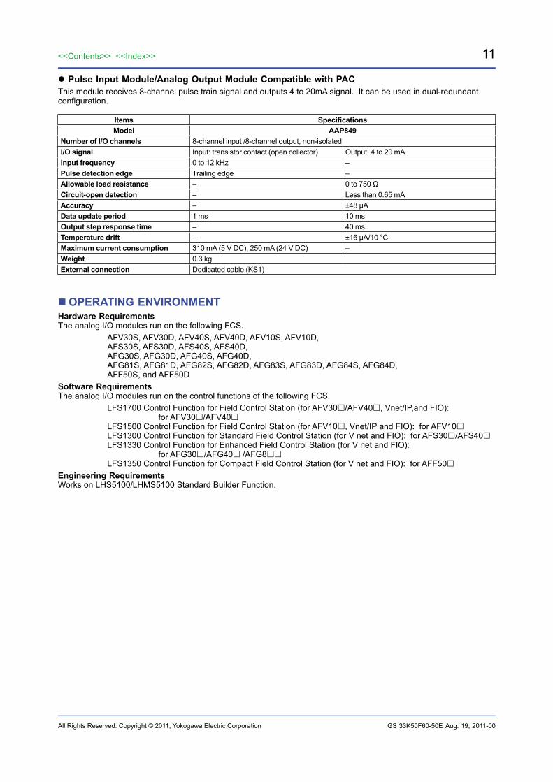
Pulse Input Module/Analog Output Module Compatible with PACThis module receives 8-channel pulse train signal and outputs 4 to 20mA signal. It can be used in dual-redundant configuration.
Items Specifications Model AAP849
Number of I/O channels 8-channel input /8-channel output, non-isolated I/O signal Input: transistor contact (open collector) Output: 4 to 20 mA Input frequency 0 to 12 kHz – Pulse detection edge Trailing edge – Allowable load resistance – 0 to 750 Ω Circuit-open detection – Less than 0.65 mA Accuracy – ±48 µA Data update period 1 ms 10 ms Output step response time – 40 ms Temperature drift – ±16 µA/10 °C Maximum current consumption 310 mA (5 V DC), 250 mA (24 V DC) – Weight 0.3 kg External connection Dedicated cable (KS1)
OPERATING ENVIRONMENTHardware RequirementsThe analog I/O modules run on the following FCS.
AFV30S, AFV30D, AFV40S, AFV40D, AFV10S, AFV10D, AFS30S, AFS30D, AFS40S, AFS40D, AFG30S, AFG30D, AFG40S, AFG40D, AFG81S, AFG81D, AFG82S, AFG82D, AFG83S, AFG83D, AFG84S, AFG84D, AFF50S, and AFF50D
Software RequirementsThe analog I/O modules run on the control functions of the following FCS.
LFS1700 Control Function for Field Control Station (for AFV30/AFV40, Vnet/IP,and FIO): for AFV30/AFV40
LFS1500 Control Function for Field Control Station (for AFV10, Vnet/IP and FIO): for AFV10 LFS1300 Control Function for Standard Field Control Station (for V net and FIO): for AFS30/AFS40 LFS1330 Control Function for Enhanced Field Control Station (for V net and FIO):
for AFG30/AFG40 /AFG8 LFS1350 Control Function for Compact Field Control Station (for V net and FIO): for AFF50
Engineering RequirementsWorks on LHS5100/LHMS5100 Standard Builder Function.

12
All Rights Reserved. Copyright © 2011, Yokogawa Electric Corporation
<<Contents>> <<Index>>
GS 33K50F60-50E
ANALOG I/O MODULE (WITH HART COMMUNICATION)The analog I/O module (with HART communication function) connected to a transmitter or a valve positioner receives HART variable (*1) in addition to exchange analog input/output data by 4 – 20 mA signal with field control stations (FCS). There are 8 types of analog I/O modules (with HART communication function).
*1: HART variable can be read by HART Command #3.
There are 8 types of analog I/O modules (with HART communication function).
Model Model Name Function AAI141-H Analog Input Module (Current Input) 16-channel, 4 to 20 mA, non-isolated AAB141-H Analog Input Module (Voltage/current Input) 16-channel, 1 to 5 V/4 to 20 mA, non-isolated AAI841-H Analog I/O Module (Current I/O) 8-channel input/8-channel output, 4 to 20 mA, non-isolated
AAB842-H Analog I/O Module (Voltage/current Input, Current Output)
8-channel input/8-channel output, 1 to 5 V/4 to 20 mA input, 4 to 20 mA output, non-isolated
AAI135-H Analog Input Module (Current Input) 8-channel, 4 to 20 mA, isolated channels AAI835-H Analog I/O Module (Current I/O) 4-channel input/4-channel output, 4 to 20 mA, isolated channels AAI143-H Analog Input Module (Current Input) 16-channel, 4 to 20 mA, isolated AAI543-H Analog Output Module (Current Output) 16-channel, 4 to 20 mA, isolated
Communication with HART DevicesThe analog I/O modules (with HART communication function) communicate with field devices and store analog data and HART variables in the Input/Output image area in the communication module. An FCS refers to and sets the Input/Output image by accessing the analog I/O modules (with HART communication function). The FCS utilizes the field device data via I/O terminals of the function block in the same way as other analog/digital I/O signals.
F08E.ai
FCS
Analog I/O module
Regulatory Control BlockSequence
Control Block
I/O image
Input/Output image
Data Setting /Reference
HART Communication Function
Figure Process Data Flow of HART Communications
Aug. 19, 2011-00

13<<Contents>> <<Index>>
All Rights Reserved. Copyright © 2011, Yokogawa Electric Corporation GS 33K50F60-50E
HART Communication Functional SpecificationsThe analog I/O modules (with HART communication function) are equipped with HART modems and eable HART communication (*1) by directly connecting the HART devices to he modules.
No. of HART devices: Max. 16 devices/moduleHART variables: Max. 32 points/module HART variables can be treated as ordinary process input data via %Z terminal connection. It is just for input.HART multidrop connection (*2): Max. 5 devices/channelHART variables data refresh cycle time : 1 second/device (When maximum of 16 devices are connected, it is 17 seconds per ESB bus connection and 19 seconds for ER bus connection.)Analog data refresh cycle time (*3): The number of ER bus node unit determines the analog data refresh cycle time in between the ER
bus master interface module (EB401) and ER bus node units. With HART communication, it takes twice as much time than without HART comunication.
No. of ER bus node unit
2 4 6Analog I/O (without HART communication) 50 ms 100 ms 200 ms
Analog I/O (with HART communication) 100 ms 200 ms 400 ms
*1: HART communication refers to HART variable communicaiton, on-demand communication, and hand held terminal (HHT) communication.
*2: It is possible to connect only input devices. This connection does not support analog data value nor burst function.*3: Field control units (AFV30 and AFV40) do not support ER bus node unit (ANR10).
HART Communication Specifications
Table HART Communication Specifications
Function Description Communication mode Serial half duplex, start-stop synchronization, 1 start/ 8 bit/ odd parity/ 1 stop Applicable standard HART Protocol Revision 5.7 (*1)Transmission speed 1200 ±2 bps
Modulation technique Binary phase-continuous FSK 1: 1200 Hz ±1 %, 0: 2200 Hz ±1%
Frame length
5 to 267 bytes Contents of max. 267 bytes:
Delimiter: 1 Address: 5 Command: 1 Byte count: 1 Data: 255 (includes two bytes of response code) Check byte: 1
Frame detection 3 byte header byte-count carrier (ON/OFF) Preamble: 5 to 20 bytes
Error detection coding Longitudinal/vertical parity Response time Max. 28 characters (256.7 ms) No response timer 33 characters (305 ms) for primary, 41 characters (380 ms) for secondary Bus monitor 8 characters (75 ms) Response window 20 ms
*1: The HART 5, 6, and 7 devices can be connected but applying the HART protocol 5.7 function.
Aug. 19, 2011-00

14
All Rights Reserved. Copyright © 2011, Yokogawa Electric Corporation
<<Contents>> <<Index>>
GS 33K50F60-50E Aug. 19, 2011-00
HART Communication System ConfigurationThe analog I/O modules (with HART communication function) can be configured dual-redundant by placing the two modules in the adjacent slots (odd number and even number slots) on the same node unit.
F09E.ai
Control Network
FCS
HIS/ENG
Analog I/O Modules
HART Devices
HIS: Human Interface Station ENG: Engineering Station
Figure HART Communication System Configuration (Dual-redundant)

15<<Contents>> <<Index>>
All Rights Reserved. Copyright © 2011, Yokogawa Electric Corporation GS 33K50F60-50E Aug. 19, 2011-00
EXTERNAL DIMENSIONS AAI141, AAV141, AAV142, AAV144, AAI841, AAB841, AAV542, AAV544, AAI143, AAI543, AAT141,
AAR181, AAI135, AAI835, AAP135, AAB141, AAB842
107.5
9432.8
130
Unit : mm
F10E.ai
AAT145, AAP849
32.8
(127.2)
125.51.7
130
Unit : mm
F11E.ai
112

16
All Rights Reserved. Copyright © 2011, Yokogawa Electric Corporation
<<Contents>> <<Index>>
GS 33K50F60-50E Aug. 19, 2011-00
AAR145
32.8
(127.2)
125.51.7
130
Unit : mm
F12E.ai
112
AAP149
32.8
(127.2)
125.51.7
130
Unit : mm
F13E.ai
112
17<<Contents>> <<Index>>
All Rights Reserved. Copyright © 2011, Yokogawa Electric Corporation GS 33K50F60-50E Apr. 1, 2013-00
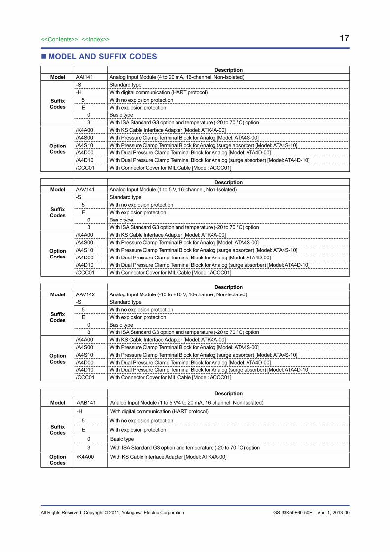
MODEL AND SUFFIX CODESDescription
Model AAI141 Analog Input Module (4 to 20 mA, 16-channel, Non-Isolated)
Suffix Codes
-S Standard type -H With digital communication (HART protocol) 5 With no explosion protection E With explosion protection 0 Basic type 3 With ISA Standard G3 option and temperature (-20 to 70 °C) option
Option Codes
/K4A00 With KS Cable Interface Adapter [Model: ATK4A-00] /A4S00 With Pressure Clamp Terminal Block for Analog [Model: ATA4S-00] /A4S10 With Pressure Clamp Terminal Block for Analog (surge absorber) [Model: ATA4S-10] /A4D00 With Dual Pressure Clamp Terminal Block for Analog [Model: ATA4D-00]/A4D10 With Dual Pressure Clamp Terminal Block for Analog (surge absorber) [Model: ATA4D-10] /CCC01 With Connector Cover for MIL Cable [Model: ACCC01]
Description Model AAV141 Analog Input Module (1 to 5 V, 16-channel, Non-Isolated)
Suffix Codes
-S Standard type 5 With no explosion protection E With explosion protection 0 Basic type 3 With ISA Standard G3 option and temperature (-20 to 70 °C) option
Option Codes
/K4A00 With KS Cable Interface Adapter [Model: ATK4A-00] /A4S00 With Pressure Clamp Terminal Block for Analog [Model: ATA4S-00] /A4S10 With Pressure Clamp Terminal Block for Analog (surge absorber) [Model: ATA4S-10] /A4D00 With Dual Pressure Clamp Terminal Block for Analog [Model: ATA4D-00]/A4D10 With Dual Pressure Clamp Terminal Block for Analog (surge absorber) [Model: ATA4D-10] /CCC01 With Connector Cover for MIL Cable [Model: ACCC01]
Description Model AAV142 Analog Input Module (-10 to +10 V, 16-channel, Non-Isolated)
Suffix Codes
-S Standard type 5 With no explosion protection E With explosion protection 0 Basic type 3 With ISA Standard G3 option and temperature (-20 to 70 °C) option
Option Codes
/K4A00 With KS Cable Interface Adapter [Model: ATK4A-00] /A4S00 With Pressure Clamp Terminal Block for Analog [Model: ATA4S-00] /A4S10 With Pressure Clamp Terminal Block for Analog (surge absorber) [Model: ATA4S-10] /A4D00 With Dual Pressure Clamp Terminal Block for Analog [Model: ATA4D-00]/A4D10 With Dual Pressure Clamp Terminal Block for Analog (surge absorber) [Model: ATA4D-10] /CCC01 With Connector Cover for MIL Cable [Model: ACCC01]
DescriptionModel AAB141 Analog Input Module (1 to 5 V/4 to 20 mA, 16-channel, Non-Isolated)
Suffix Codes
-H With digital communication (HART protocol)
5 With no explosion protection
E With explosion protection
0 Basic type
3 With ISA Standard G3 option and temperature (-20 to 70 °C) option
Option Codes
/K4A00 With KS Cable Interface Adapter [Model: ATK4A-00]
18
All Rights Reserved. Copyright © 2011, Yokogawa Electric Corporation
<<Contents>> <<Index>>
GS 33K50F60-50E Apr. 1, 2013-00
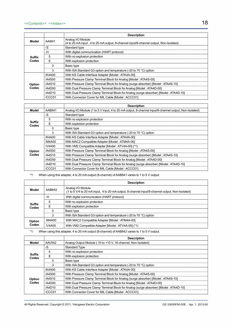
Description
Model AAI841 Analog I/O Module (4 to 20 mA input , 4 to 20 mA output, 8-channel input/8-channel output, Non-Isolated)
Suffix Codes
-S Standard type -H With digital communication (HART protocol) 5 With no explosion protection E With explosion protection 0 Basic type 3 With ISA Standard G3 option and temperature (-20 to 70 °C) option
Option Codes
/K4A00 With KS Cable Interface Adapter [Model : ATK4A-00] /A4S00 With Pressure Clamp Terminal Block for Analog [Model : ATA4S-00] /A4S10 With Pressure Clamp Terminal Block for Analog (surge absorber) [Model : ATA4S-10] /A4D00 With Dual Pressure Clamp Terminal Block for Analog [Model : ATA4D-00]/A4D10 With Dual Pressure Clamp Terminal Block for Analog (surge absorber) [Model : ATA4D-10] /CCC01 With Connector Cover for MIL Cable [Model : ACCC01]
Description Model AAB841 Analog I/O Module (1 to 5 V input, 4 to 20 mA output, 8-channel input/8-channel output, Non-Isolated)
Suffix Codes
-S Standard type 5 With no explosion protection E With explosion protection 0 Basic type 3 With ISA Standard G3 option and temperature (-20 to 70 °C) option
Option Codes
/K4A00 With KS Cable Interface Adapter [Model : ATK4A-00] /M4A00 With MAC2 Compatible Adapter [Model : ATM4A-00] /V4A00 With VM2 Compatible Adapter [Model : ATV4A-00] (*1) /A4S00 With Pressure Clamp Terminal Block for Analog [Model : ATA4S-00] /A4S10 With Pressure Clamp Terminal Block for Analog (surge absorber) [Model : ATA4S-10]/A4D00 With Dual Pressure Clamp Terminal Block for Analog [Model : ATA4D-00] /A4D10 With Dual Pressure Clamp Terminal Block for Analog (surge absorber) [Model : ATA4D-10] /CCC01 With Connector Cover for MIL Cable [Model : ACCC01]
*1: When using this adapter, 4 to 20 mA output (8-channel) of AAB841 varies to 1 to 5 V output.
Description
Model AAB842 Analog I/O Module (1 to 5 V/4 to 20 mA input, 4 to 20 mA output, 8-channel input/8-channel output, Non-Isolated)
Suffix Codes
-H With digital communication (HART protocol) 5 With no explosion protection E With explosion protection 0 Basic type 3 With ISA Standard G3 option and temperature (-20 to 70 °C) option
Option Codes
/M4A00 With MAC2 Compatible Adapter [Model : ATM4A-00]
/V4A00 With VM2 Compatible Adapter [Model : ATV4A-00] (*1)
*1: When using this adapter, 4 to 20 mA output (8-channel) of AAB842 varies to 1 to 5 V output.
Description Model AAV542 Analog Output Module (-10 to +10 V, 16-channel, Non-Isolated)
Suffix Codes
-S Standard Type 5 With no explosion protection E With explosion protection 0 Basic type 3 With ISA Standard G3 option and temperature (-20 to 70 °C) option
Option Codes
/K4A00 With KS Cable Interface Adapter [Model : ATK4A-00] /A4S00 With Pressure Clamp Terminal Block for Analog [Model : ATA4S-00] /A4S10 With Pressure Clamp Terminal Block for Analog (surge absorber) [Model : ATA4S-10] /A4D00 With Dual Pressure Clamp Terminal Block for Analog [Model : ATA4D-00]/A4D10 With Dual Pressure Clamp Terminal Block for Analog (surge absorber) [Model : ATA4D-10] /CCC01 With Connector Cover for MIL Cable [Model : ACCC01]

19<<Contents>> <<Index>>
All Rights Reserved. Copyright © 2011, Yokogawa Electric Corporation GS 33K50F60-50E Apr. 1, 2013-00
Description Model AAI143 Analog Input Module (4 to 20 mA, 16-channel, Isolated)
Suffix Codes
-S Standard type -H With digital communication (HART protocol) 5 With no explosion protection E With explosion protection 0 Basic type 3 With ISA Standard G3 option and temperature (-20 to 70 °C) option
Option Codes
/K4A00 With KS Cable Interface Adapter (For connecting AEA4D Terminal Board) [Model: ATK4A-00] /A4S00 With Pressure Clamp Terminal Block [Model: ATA4S-00] /A4S10 With Pressure Clamp Terminal Block (surge absorber) [Model: ATA4S-10] /A4D00 With Dual Pressure Clamp Terminal Block [Model: ATA4D-00]/A4D10 With Dual Pressure Clamp Terminal Block (surge absorber) [Model: ATA4D-10] /CCC01 With Connector Cover for MIL Cable [Model: ACCC01]
Description Model AAI543 Analog Output Module (4 to 20 mA, 16-channel, Isolated)
Suffix Codes
-S Standard type -H With digital communication (HART protocol) 5 Standard switch-over response in redundant configuration with no explosion protection(*1) 6 Fast switch-over response in redundant configuration with no explosion protection(*2) E Standard switch-over response in redundant configuration with explosion protection(*1) F Fast switch-over response in redundant configuration with explosion protection(*2) 0 Basic type 1 With ISA Standard G3 option 3 With ISA Standard G3 option and temperature (-20 to 70 °C) option
Option Codes
/K4A00 With KS Cable Interface Adapter (For connecting AEA4D Terminal Board) [Model: ATK4A-00] /A4S00 With Pressure Clamp Terminal Block [Model: ATA4S-00] /A4S10 With Pressure Clamp Terminal Block (surge absorber) [Model: ATA4S-10] /A4D00 With Dual Pressure Clamp Terminal Block [Model: ATA4D-00]/A4D10 With Dual Pressure Clamp Terminal Block (surge absorber) [Model: ATA4D-10] /CCC01 With Connector Cover for MIL Cable [Model: ACCC01]
*1: If “standard switch-over response in redundant configuration” is selected, “basic type” or “with ISA Standard G3 option and temperature (-20 to 70 °C) option” may be specified.
*2: If “fast switch-over response in redundant configuration” is selected, “basic type” or “with ISA Standard G3 option” may be specified.
Description Model AAV144 Analog Input Module (-10 to +10 V, 16-channel, Isolated)
Suffix Codes
-S Standard type 5 With no explosion protection E With explosion protection 0 Basic type 3 With ISA Standard G3 option and temperature (-20 to 70 °C) option
Option Codes
/K4A00 With KS Cable Interface Adapter [Model: ATK4A-00] /A4S00 With Pressure Clamp Terminal Block for Analog [Model: ATA4S-00] /A4S10 With Pressure Clamp Terminal Block for Analog (surge absorber) [Model: ATA4S-10] /A4D00 With Dual Pressure Clamp Terminal Block for Analog [Model: ATA4D-00]/A4D10 With Dual Pressure Clamp Terminal Block for Analog (surge absorber) [Model: ATA4D-10] /CCC01 With Connector Cover for MIL Cable [Model: ACCC01]

20
All Rights Reserved. Copyright © 2011, Yokogawa Electric Corporation
<<Contents>> <<Index>>
GS 33K50F60-50E Apr. 1, 2013-00
Description Model AAV544 Analog Output Module (-10 to +10 V, 16-channel, Isolated)
Suffix Codes
-S Standard Type 5 With no explosion protection E With explosion protection 0 Basic type 3 With ISA Standard G3 option and temperature (-20 to 70 °C) option
Option Codes
/K4A00 With KS Cable Interface Adapter [Model : ATK4A-00] /A4S00 With Pressure Clamp Terminal Block for Analog [Model : ATA4S-00] /A4S10 With Pressure Clamp Terminal Block for Analog (surge absorber) [Model : ATA4S-10] /A4D00 With Dual Pressure Clamp Terminal Block for Analog [Model : ATA4D-00]/A4D10 With Dual Pressure Clamp Terminal Block for Analog (surge absorber) [Model : ATA4D-10] /CCC01 With Connector Cover for MIL Cable [Model : ACCC01]
Description Model AAT141 TC/mV Input Module (16-channel, Isolated)
Suffix Codes
-S Standard type 5 With no explosion protection E With explosion protection 0 Basic type 3 With ISA Standard G3 option and temperature (-20 to 70 °C) option
Option Codes
/T4S00 With Pressure Clamp Terminal Block for Thermocouple/mV [Model: ATT4S-00] /T4S10 With Pressure Clamp Terminal Block for Thermocouple/mV (surge absorber) [Model: ATT4S-10] /T4D00 With Dual Pressure Clamp Terminal Block for Thermocouple/mV [Model: ATT4D-00] /T4D10 With Dual Pressure Clamp Terminal Block for Thermocouple/mV (surge absorber) [Model: ATT4D-10]/CCC01 With Connector Cover for MIL Cable [Model: ACCC01]
Description Model AAR181 RTD Input Module (12-channel, Isolated)
Suffix Codes
-S Standard type 5 With no explosion protection E With explosion protection 0 Basic type 3 With ISA Standard G3 option and temperature (-20 to 70 °C) option
Option Codes
/R8S00 With Pressure Clamp Terminal Block for RTD [Model: ATR8S-00] /R8S10 With Pressure Clamp Terminal Block for RTD (surge absorber) [Model: ATR8S-10] /R8D00 With Dual Pressure Clamp Terminal Block for RTD [Model: ATR8D-00]/R8D10 With Dual Pressure Clamp Terminal Block for RTD (surge absorber) [Model: ATR8D-10] /CCC01 With Connector Cover for MIL Cable [Model: ACCC01]
Description Model AAI135 Analog Input Module (4 to 20 mA, 8-channel, Isolated channels)
Suffix Codes
-S Standard type -H With digital communication (HART protocol) 5 With no explosion protection E With explosion protection 0 Basic type 3 With ISA Standard G3 option and temperature (-20 to 70 °C) option
Option Codes
/13A00 With KS Cable Interface Adapter [Model: ATI3A-00] /K4A00 With KS Cable Interface Adapter [Model: ATK4A-00] /13S00 With Pressure Clamp Terminal Block for Isolated Analog [Model: ATI3S-00] /13S10 With Pressure Clamp Terminal Block for Isolated Analog (surge absorber) [Model: ATI3S-10]/13D00 With Dual Pressure Clamp Terminal Block for Isolated Analog [Model: ATI3D-00]/13D10 With Dual Pressure Clamp Terminal Block for Isolated Analog (surge absorber) [Model: ATI3D-10] /CCC01 With Connector Cover for MIL Cable [Model: ACCC01]

21<<Contents>> <<Index>>
All Rights Reserved. Copyright © 2011, Yokogawa Electric Corporation GS 33K50F60-50E
Description Model AAI835 Analog I/O Module (4 to 20 mA, 4-channel input/4-channel output, Isolated channels)
Suffix Codes
-S Standard type -H With digital communication (HART protocol) 5 With no explosion protection E With explosion protection 0 Basic type 3 With ISA Standard G3 option and temperature (-20 to 70 °C) option
Option Codes
/B3A00 With KS Cable Interface Adapter [Model: ATB3A-00] /K4A00 With KS Cable Interface Adapter [Model: ATK4A-00] /13S00 With Pressure Clamp Terminal Block for Isolated Analog [Model: ATI3S-00] /13S10 With Pressure Clamp Terminal Block for Isolated Analog (surge absorber) [Model: ATI3S-10]/13D00 With Dual Pressure Clamp Terminal Block for Isolated Analog [Model: ATI3D-00]/13D10 With Dual Pressure Clamp Terminal Block for Isolated Analog (surge absorber) [Model: ATI3D-10] /CCC01 With Connector Cover for MIL Cable [Model: ACCC01]
Description Model AAT145 TC/mV Input Module (16-channel, Isolated channels)
Suffix Codes
-S Standard type 5 With no explosion protection E With explosion protection 0 Basic type 3 With ISA Standard G3 option and temperature (-20 to 70 °C) option
Description Model AAR145 RTD/POT Input Module (16-channel, Isolated channels)
Suffix Codes
-S Standard type 5 With no explosion protection E With explosion protection 0 Basic type 3 With ISA Standard G3 option and temperature (-20 to 70 °C) option
Description Model AAP135 Pulse Input Module (8-channel, Pulse count, 0 to 10 kHz, Isolated channels)
Suffix Codes
-S Standard type 5 With no explosion protection E With explosion protection 0 Basic type 3 With ISA Standard G3 option and temperature (-20 to 70 °C) option
Option Codes
/13A00 With KS Cable Interface Adapter [Model: ATI3A-00] /K4A00 With KS Cable Interface Adapter [Model: ATK4A-00]/13S00 With Pressure Clamp Terminal Block for Pulse [Model: ATI3S-00]/13S10 With Pressure Clamp Terminal Block for Pulse (surge absorber) [Model: ATI3S-10]/13D00 With Dual Pressure Clamp Terminal Block for Pulse [Model: ATI3D-00]/13D10 With Dual Pressure Clamp Terminal Block for Pulse (surge absorber) [Model: ATI3D-10]/CCC01 With Connector Cover for MIL Cable [Model: ACCC01]
Description Model AAP149 Pulse Input Module PM1 compatible (16-channel, Pulse count, 0 to 6 kHz, Non-Isolated)
Suffix Codes
-S Standard type 0 Always 0 0 Basic type 1 With ISA Standard G3 option
Apr. 1, 2013-00

22
All Rights Reserved. Copyright © 2011, Yokogawa Electric Corporation
<<Contents>> <<Index>>
GS 33K50F60-50ESubject to change without notice.
Apr. 1, 2013-00
Description
Model AAP849 Pulse Input Module/ Analog Output Module for compatible PAC (Pulse count Input, 4 to 20 mA output, 8-channel input / 8-channel output, Non-Isolated)
Suffix Codes
-S Standard type 0 Always 0 0 Basic type 1 With ISA Standard G3 option
ORDERING INFORMATIONSpecify the model and suffix codes. For selecting the right products for explosion protection, please refer to TI 33Q01J30-01E without fail.
TRADEMARKS• CENTUM is a registered trademark of Yokogawa Electric Corporation.• HART is a registered trademark of the HART Communication Foundation.• Other company and product names appearing in this document are trademarks or registered trademarks of their
respective holders.