general overview of hvdc transmission system
TRANSCRIPT

General Overview of HVDC Transmission System

WHAT IS HVDC ? High Voltage Direct Current Transmission
Only Active Power Flow is associated with HVDC: P.
High Voltage Alternative Current Transmission Both Active and Reactive Power (Var) Flows with AC: P and Q
HVDC
1-Phase(±)
HVAC 3-Phase

What is HVDC ? Basic Image : DC vs. AC Transmission
Distance
+
–
R
S
T
Sending Voltage/ Power
Receiving Voltage/ Power
Distance Sending Voltage/ Power
Receiving Voltage/ Power
Voltage/Power – Decrease (Loss) Angle – No Change
Voltage/Power – Decrease (Loss) Angle – Change (Reactive Power)
DC 1-Phase (±)
AC 3-Phase

Sending Side Receiving Side Direct Current Id=(Vs-Vr)/R
WHAT IS HVDC ?
Sending Voltage Vs
Receiving Voltage Vr
RVVVPower rss )( −
= Basic Power Flow Equations Only Governed by Ohm’s Law
AC
R
R
AC Vs Vr
+
–
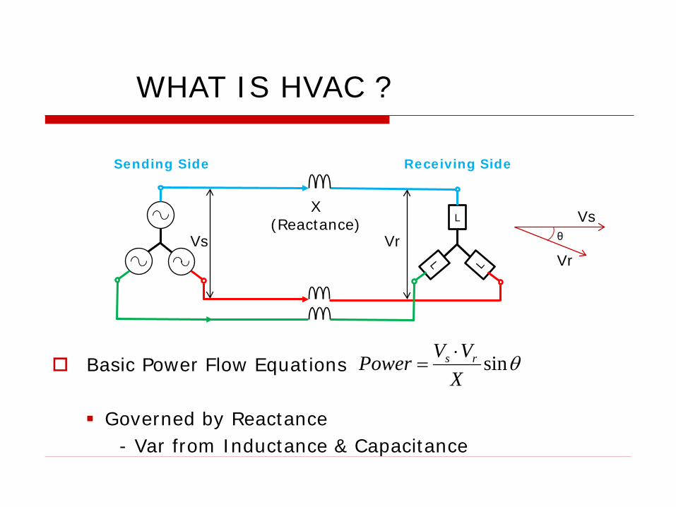
WHAT IS HVAC ?
θsinXVVPower rs ⋅
= Basic Power Flow Equations Governed by Reactance
- Var from Inductance & Capacitance
L X
(Reactance) Vs Vr θ
Vs
Vr
Sending Side Receiving Side
HVDC Advantages (1) Long-Haul Over Head Line (>500 ~ 1000km) Bulk Power Transmission (>1 ~ 2 GW)
No limitation of stability (Free from stability & capacitance limitation)
HVDC transmission line has less right of way requirement & less expensive in construction (HVDC 2-phase; HVAC 3-phase)
Lower transmission loss because of no reactive loss
Lower insulation/clearance of conductor (DC Voltage is about 71% of the AC Peak Voltage. AC is defined by RMS)
Power transmission between asynchronous AC systems

HVDC Advantages (2) Fast Power Flow control
Enhancement of AC system stability
Supplying more active power where AC system is at the
limit of its Short Circuit Capability
HVDC Disadvantages HVDC is generally less reliable and has lower availability
than HVAC. Mainly due to the extra conversion equipment and maintenance
difficulty.
Tapping for Multiple grids is difficult.
HVDC circuit breakers are difficult Some mechanism must be included in the circuit breaker to force
current to zero
Pollution deterioration of Outdoor Insulator is faster Static Charge effect
AC Filters are required to absorb harmonic component
Clean room (Dust free) for Thyristor Valve is necessary

# Item HVDC HVAC
1 Long-Haul OHL Bulk Transmission Capacity
High (> 1~2GW) Limited
2 Long-Haul Transmission Stability No Limit Limited
3 Right-of-Way for Bulk Transmission OHL Low High
4 Long-Haul Transmission Loss Low High
5 Insulation / Clearance Low High
6 System Connection Asynchronous Synchronous
7 Power Flow Control Easy and Fast Difficult
6 Multiple terminal (Tapping) Difficult and Costly Simple and Easy
7 Short Circuit Limitation Effective Not Effective
8 Pollution Effect • More Pronounced • Higher insulator creepage is required
Relatively less
Comparison HVDC with HVAC

Why HVDC rather than HVAC ?
Cheaper in Long-Haul Bulk Power transmission
Asynchronous link
Accurate Control of power flow – both magnitude and direction
Fault isolation
Improved link stability

~100 m ~50 m
400~500 kV AC Lines 400~500 kV DC Line
Comparison of Right of Way for 2 GW
1~2GW Bulk Power Transmission

Cost comparison of HVDC & HVAC OHL Transmission
DC terminal Cost
AC terminal Cost
Cost Break-Even Distance
Distance
AC Line Cost
DC Line Cost
600 ~ 800 km
Total AC Cost
Total DC Cost
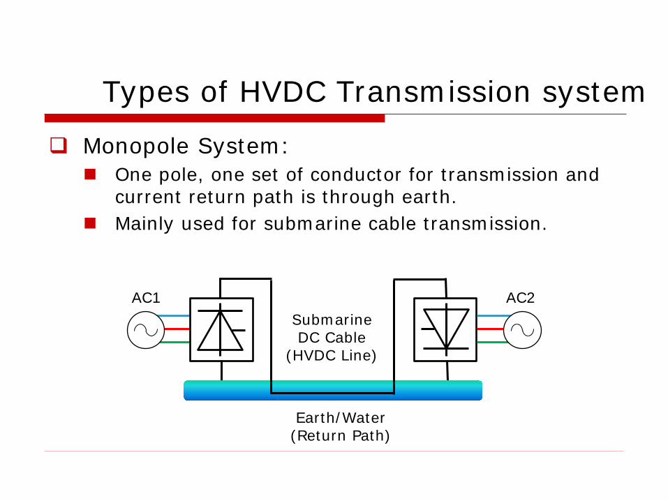
Types of HVDC Transmission system
Monopole System: One pole, one set of conductor for transmission and
current return path is through earth. Mainly used for submarine cable transmission.
AC1 AC2 Submarine DC Cable
(HVDC Line)
Earth/Water (Return Path)
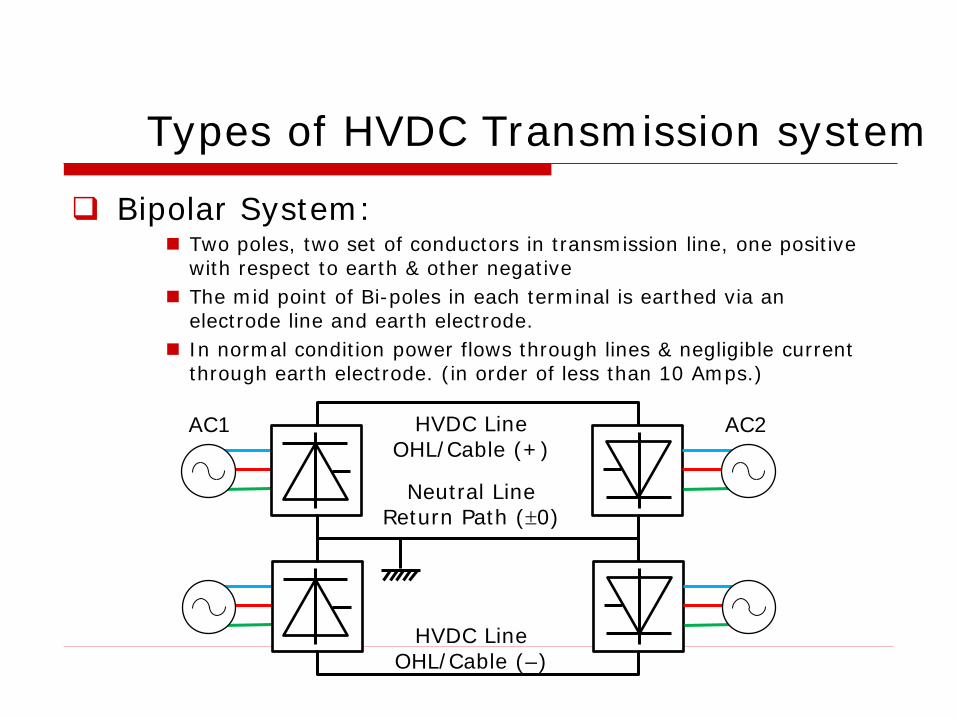
Bipolar System: Two poles, two set of conductors in transmission line, one positive
with respect to earth & other negative The mid point of Bi-poles in each terminal is earthed via an
electrode line and earth electrode. In normal condition power flows through lines & negligible current
through earth electrode. (in order of less than 10 Amps.)
Types of HVDC Transmission system
AC1 AC2 HVDC Line OHL/Cable (+)
HVDC Line OHL/Cable (–)
Neutral Line Return Path (±0)

Back To Back: Usually bipolar without earth return. Converter & inverters are located at the same place. No HVDC Transmission line. Provides Asynchronous tie between two different AC network Power transfer can be in either direction
AC1 AC2
Types of HVDC Transmission system
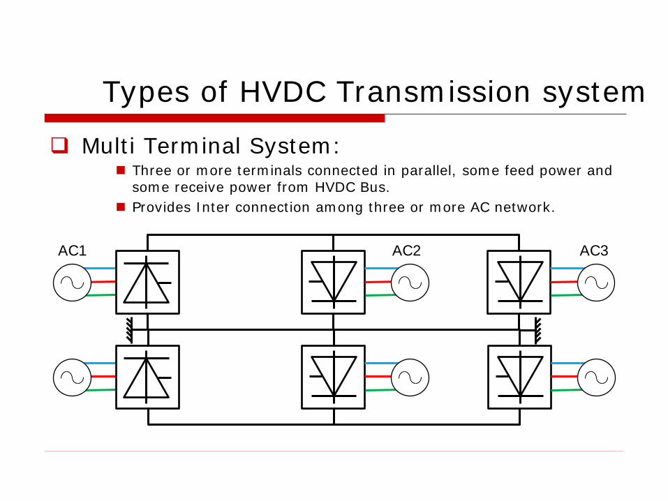
AC1 AC3
Multi Terminal System: Three or more terminals connected in parallel, some feed power and
some receive power from HVDC Bus. Provides Inter connection among three or more AC network.
AC2
Types of HVDC Transmission system
HOW HVDC WORKS

Basic Diagram of HVDC System
DC LINE AC 1
TERMINAL A (Converter)
TERMINAL B (Converter) AC 2
Pd = Vd Id
FILTER
Vd
Ld Id
FILTER
Ld
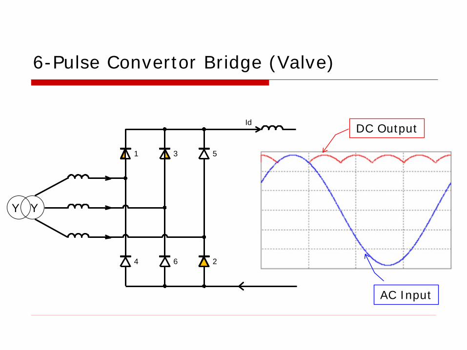
3
6 4
1
2
Id
5
AC Input
DC Output
Y Y
6-Pulse Convertor Bridge (Valve)
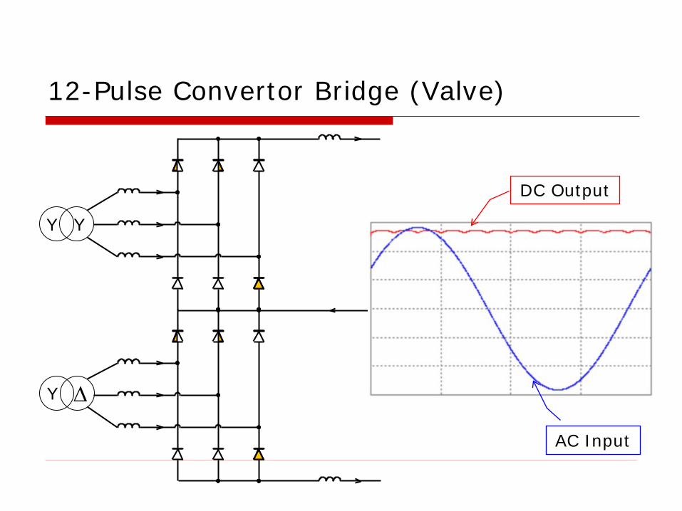
12-Pulse Convertor Bridge (Valve)
AC Input
DC Output
Y Y
∆ Y

HVDC Thyristor Valve (1)
Single Valve
Double Valve Quadruple Valve
(Multiple Valve Unit : MVU)

HVDC Thyristor Valve (2)
Thyristor
Thyristor Module
Drive Unit
Multiple Valve Unit
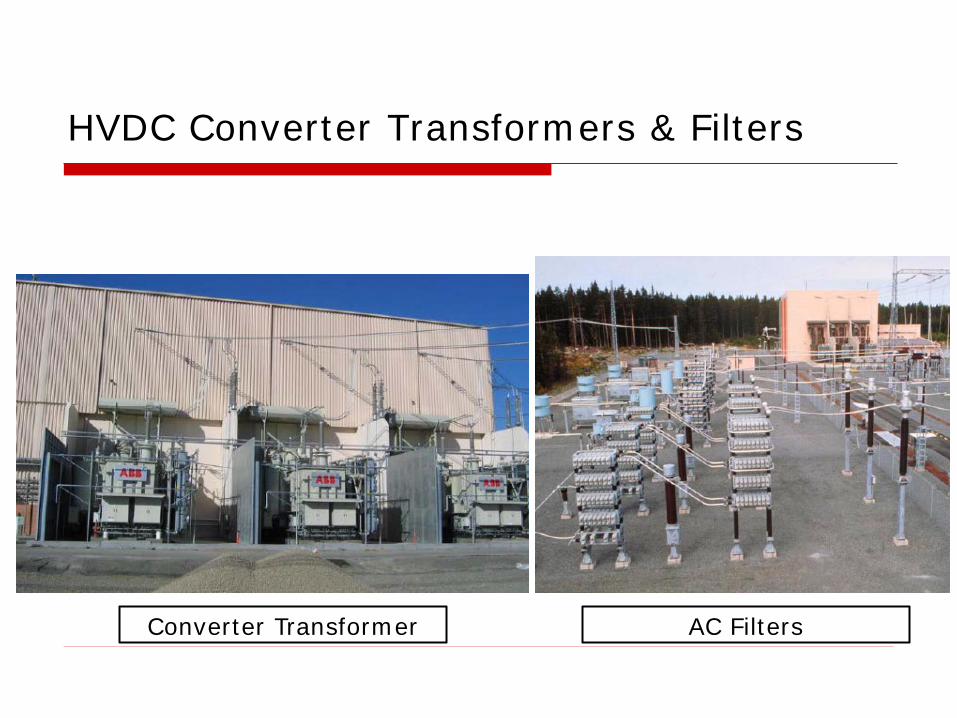
HVDC Converter Transformers & Filters
Converter Transformer AC Filters
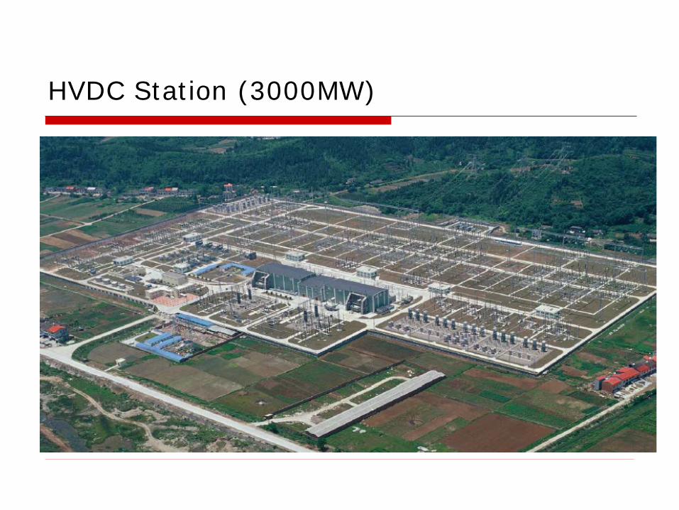
HVDC Station (3000MW)
BIPOLE HVDC
MODES OF OPERATION

BASIC HVDC Single Line Diagram
DC OH Line
Converter Transformer
DC Filter:
DC Filter:
Thyristor Valves
AC Bus
AC Filters
Smoothing Reactor
Converter Transformer
DC Filter:
DC Filter:
Thyristor Valves
AC Bus
AC Filters
Smoothing Reactor
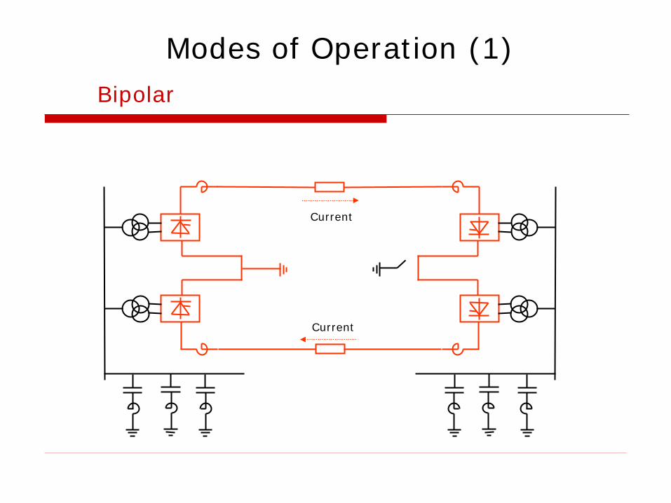
Modes of Operation (1) Bipolar
Current
Current
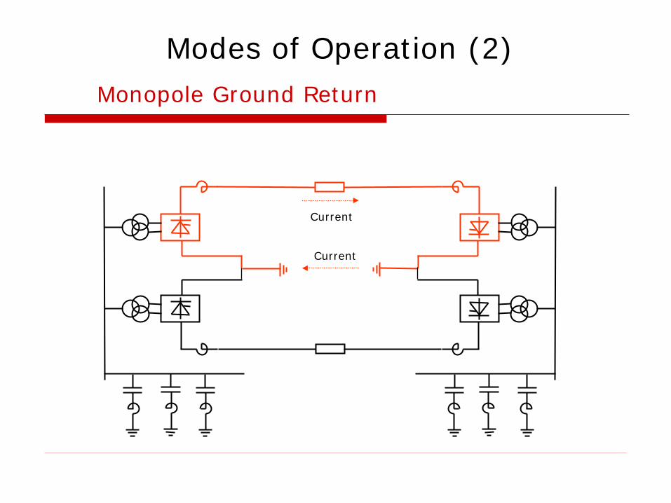
Monopole Ground Return
Current
Modes of Operation (2)
Current
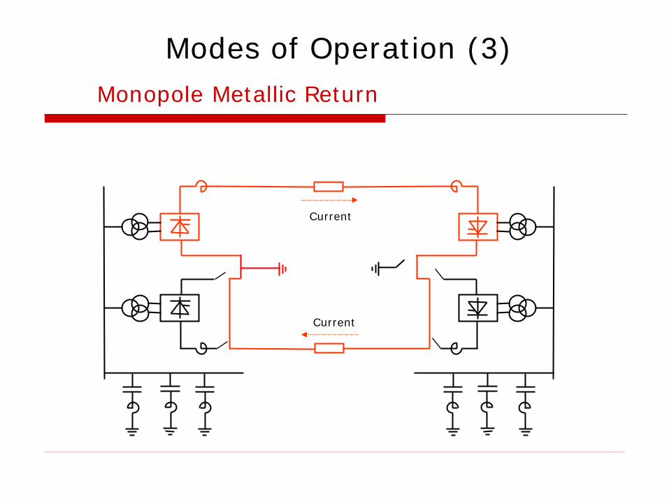
Modes of Operation (3) Monopole Metallic Return
Current
Current