general models se100mj/nj and se200mj/nj … · * in case of fm-nonincendive type, 135ma...
TRANSCRIPT

GeneralSpecifications
<<Contents>> <<Index>>
Models SE100MJ/NJ and SE200MJ/NJMagentic FlowmeterModels SE14 Magnetic Flow ConverterModels SE100DJ/EJ, SE200DJ/EJand SE300DJ Magnetic Flow Tube
Yokogawa Electric Corporation2-9-32, Nakacho, Musashino-shi, Tokyo, 180-8750 JapanTel.: 81-422 52-4443 Fax.: 81-422 52-2018
GS 01E10A01-01E
GS 01E10A01-01E© Copyright Mar. 1998(YK)13th Edition Oct. 2005(KP)
Solution to your profitabilityADMAG SE is the Safe and Easy magnetic flowmeterwhich makes your job simple and effective. You willincrease the productivity and profitability. The installa-tion, operation, and maintenance are all safe andeasy.
ADMAG SE is equipped with a dual compartmenthousing providing ease of wiring while isolating theelectronics from the environment. It is also preparedwith HART or BRAIN communication as standard andits light weight makes installation easy .
FEATURES High Reliability
• Based on Field Proven Technology• Proven Construction• Long Term Durability
Compliance to World Market Requirements
• General Safety• CE mark, C -Tick mark• Explosion Proof• ISO Standard
High Accuracy (0.5% of flow rate)
Easy Operation and Maintenance
• Parameter Setting with Touch Control• Self Diagnostics• Light Weight and Easy Installation• Face to Face Length conform to ISO Standard
(Flange Type) Easily Visible Display
• The Large Visible LCD Panel Communication Capability
• HART or BRAIN as standard Cost-effective
Note : HART is a registered trademark of the HARTCommunication Foundation .
STANDARD SPECIFICATIONS
Magnetic Flow Converter for SE100MJ/NJ,SE200MJ/NJ; SE14Note •For models with no setting switches, a hand-
held terminal is necessary to set parameters.•Pulse output, status output and alarm output use commom terminals, therefore, these functions are not available at the same time.
Excitation method: Pulsed DC excitationOutput Signal Current Output: 4 to 20 mA DC (Load resistance
600 ohm maximum.). Transistor Contact Output(Open-collector):
Pulse, alarm or status output selected byparameter setting (Contact rating: 30VDC(OFF), 200mA*(ON))
* In case of FM-Nonincendive type, 135mA
Communication:HART or BRAIN (Superimposed on the 4 to 20mADC signal)
Conditions of Communication Line:Load Resistance: (including cable resistance)HART: 230 to 600 ohm, depending on q’ty of
field devices connected to the loop(multidrop mode)
BRAIN: 250 to 600 ohmLoad Capacitance: 0.22 µF maximumLoad Inductance: 3.3 mH maximumDistance from Power Line: 15 cm(0.6 ft) or more
(Parallel wiring should be avoided.)Input Impedance of Receiver Connected to the
Receiving Resistance: 10k ohm or larger(at 2.4 kHz) (only for HART)
Maximum Cable Length: 2 km* (6500 ft) (whenpolyethylene-insulated PVC-sheathedcontrol cables (CEV cables) are used)
* In case of FM-Nonincendive type, 1.5km(4875ft)Instantaneous Flow Rate Display Function:
Flow rate can be displayed either inengineering units or in percent of span.(for models with indicator)
Totalizer Display Function:Totalized volume in engineering unitscan be displayed by setting a totalizingfactor. (for models with indicator)
Span Setting Function:Volumetric flow setting is available bysetting volume unit, time unit, flow ratevalue and flow tube size.
Volume Unit: m3, l, cm3, gallon(US), barrel(=158.987L)Velocity Unit: m, ftTime Unit: sec., min., hour, dayFlow Tube Size: mm, inch

2
All Rights Reserved. Copyright © 1998, Yokogawa Electric Corporation
<<Contents>> <<Index>>
GS 01E10A01-01E
Data Security During Power Failure:Data storage in EEPROM - no back-upbattery required.
Damping Time Constant:Settable from 0.5 second to 200 seconds.(63% response time)
Pulse Output Function:Scaled pulse can be output by setting apulse factor.
Pulse Width:Duty 50% or fixed pulse width(0.5, 1, 20, 33, 50, or 100ms) - userselectable.
Output Rate : 0.0001 to 1000pps (whenpulse output function is selected.)
Status Output Function:One of the followings is selected byparameter setting.
• Auto 2 Ranges Status Output:Indicates the selected range for automaticdual range function.
• Forward and Reverse Status Output:Indicates the flow direction for forward andreverse flow measurement mode.
• Totalization Status Output:Indicates that the internal totalized valueexceeds the set value.
• Low Limit Alarm:Indicates that flow rate under the low limitset value.
Alarm Output Function:Indicates that an alarm occurs (NormalClose Fixed).
Self Diagnostics Function:Converter failure, flow tube failure,erroneous setting, etc. can be diagnosedand displayed (for models with indicator).
Touch Control:Parameter setting operation by infraredswitches. (for models with indicator andsetting switches)
Electrical Connection:ANSI 1/2NPT female, DIN Pg13.5 female,ISO M20 X 1.5 female, JIS G1/2 female
Terminal Connection: M4 size screw terminalCase Material: Aluminum alloyCoating: Polyurethane corrosion-resistant coating
Deep sea moss green (Munsell 0.6GY3.1/2.0)Degrees of Protection:
IP67, JIS C0920 Water tight protection
Mounting(SE14): 2-inch pipe mounting
Magnetic Flow Tube for SE100MJ/NJ,SE200MJ/NJ; SE100DJ/EJ,SE200DJ/EJ and300DJ
Degrees of Protection:IP67, JIS C0920 Water tight protection
Size in mm (in.):15 (0.5), 25 (1), 40 (1.5), 50 (2), 80 (3), 100 (4), 150(6), 200 (8), 250 (10)*, 300 (12)*, 350 (14)*, 400 (16)*
*Remote type only
Coating:Terminal Box(SE***DJ/EJ):Polyurethane corrosion-resistant coating,Deep sea moss green (Munsell 0.6Y3.1/2.0)
• Terminal box is coated for all type
Body:Polyurethane corrosion-resistant coating,Deep sea moss green (Munsell 0.6Y3.1/2.0)
• All sizes of carbon steel flange type• 150 and 200 mm of wafer type
No coating• 15 to 100mm of stainless steel flange type• 15 to 100mm of wafer type
Flow Tube Material:Size 15 to 100mm (0.5 to 4in.)
Housing: Stainless steel (15mm: SCS11, 25 to100mm: SUS304)
Mini-flange for wafer conn.: Stainless steel(SUS430)Flange: Carbon steel (SS400) or stainless
steel (SUS304)Pipe: Stainless steel (15 to 25mm:SCS13,
40 to 100mm: SUS304)Terminal box(SE***DJ/EJ): Aluminum alloy
Size 150 to 400mm (6 to 16in.)Housing: Carbon steel (SS400)Mini-flange for wafer conn.: Carbon steel (SS400)Flange: Carbon steel (SS400) or stainless steel (SUS304)Pipe: Stainless steel (SUS304)Terminal box(SE***DJ/EJ): Aluminum alloy
Wetted Part Material:Lining: Fluorocarbon PFAElecctrode: Stainless steel (SUS316L), Hastelloy
C (equivalent to Hastelloy C-276)Titanium, Tantalum, Platinum-Iridium,Tungsten Carbide.
Earth Ring: • Size 15 to 200mmStainless steel (SUS316), HastelloyC (equivalent to Hastelloy C-276),Titanium, PFA lining + Earthelectrode(Tantalum/Platinum-iridium)• Size 250, 300mm Stainless steel(SUS316), Hastelloy C (equivalent toHastelloy C-276), Titanium• Size 350, 400mmStainless steel (SUS316)
Note: Hastelloy is a registered trademark of HaynesInternational Inc.
Gasket:• VALQUA#4010; Fluoro rubber, viton (between
flow tube body and earth ring; for optionalcode/FRG)
• Non-asbestos joint sheet sheathed with fluororesin PTFE (between earth ring and processflange; for optional code or /BSF)
Other gaskets between flow tube and earth ring;• VALQUA#4010(Mixing#RCD970); Alkari
resistance gasket for PVC piping(Fluororubber)
• VALQUA#4010(Mixing#RCD470); Acidresistance gasket for PVC piping(Fluororubber)
Contact YOKOGAWA office.(Refer to TI 1E6A0-06E)
Electrode Construction: External insertion typeElectrical Connection(SE***DJ/EJ):
ANSI 1/2NPT female, DIN Pg13.5 female,ISO M20 X 1.5 female, JIS G1/2 female
Grounding: 100Ω or less*In case of explosion proof type, follow the domesticelectrical requirements as regulated in each country.
13th Edition Oct.15,2005-00

3<<Contents>> <<Index>>
All Rights Reserved. Copyright © 1998, Yokogawa Electric Corporation GS 01E10A01-01E
SE14• Explosion proof for Class I, Division 1, Groups
A, B, C & D.Dust-ignition proof for Class II/III, Division 1,Groups E, F & G.
Temp. Code ; T6Enclosure; NEMA 4XAmbient Temp.: -20 to 60°CMaximum power supply voltage: 250 Vac/ 110 Vdc
• Nonincendive for Class I, Division 2, Groups A,B, C & D.
Suitable for ClassII, Division 2, Groups F& G;Class III, Division 1 and 2.Temp. Code; T4Enclosure; NEMA 4XAmbient Temp.: -20 to 60°CMaximum power supply voltage: 250 Vac/ 110 Vdc
• Nonincendive Field Wiring ParameterOutput
signal
Signal
nameAnalog
output
Current
output
Voc
(V)
19.7
Isc
(mA)
21.6
Ca
(F)
0.3
La
(mH)
10
The nonincendive field wiring concept allows
interconnection of two FM Approved
Nonincendive Apparatuses with nonincendive
field wiring parameters not specifically examined
in combination as a system when:
VocVmax, IscImax, CaCi+Ccable, LaLi+Lcable T00-1.EPS
Input
signal
Signal
nameContact
output
Transistor
output
The nonincendive field wiring concept allows
interconnection of two FM Approved
Nonincendive Apparatuses with nonincendive
field wiring parameters not specifically examined
in combination as a system when:
Voc or VtVmax, Isc or ItImax,
CaCi+Ccable, LaLi+Lcable
Vmax
(V)
30
Imax
(mA)
135
Ci
(F)
0.1
Li
(mH)
0
T00-2.EPS
Note; Installation shall be in accordance with themanufacture’s instructions and NationalElectric code, ANSI/NFPA-70.
SE100EJ and SE200EJExplosion proof for Class I, Division 1, Groups A,B, C & D.Dust-ignition proof for Class II/III, Division 1,Groups E, F & G.Intrinsically safe (electrodes) for Class I, Division1,Groups A, B, C & D.Electrode circuit Vmax = 250 Vac/dcTemp. Code: T6 T5 T4 T3Max. Process Temp.: +70 +85 +120 +150˚CEnclosure ; NEMA 4XAmbient Temp.: -20 to 60°CNote; • Installation shall be in accordance with the
manufacturer’s instructions and NationalElectric code, ANSI/NFPA-70.
• There is no need of the conduit seal forboth of Division 1 and 2 hazardouslocations because this product is sealedat factory.
HAZARDOUS AREA CLASSIFICATIONCENELEC ATEX(KEMA): Applicable Standard:
EN50014, EN50018, EN50020, EN50028,EN60529, EN61010-1
Certificate: KEMA 98ATEX3230 SE100NJ and SE200NJ
Group: IICategory: 2GEEx dm[ia] II C T6..T3Electrode Circuit Um; 250Vac/dcExcitation Circuit; 41V max. 6/6.25HzTemp. Class; T6 T5 T4 T3Process Temp.; 70 85 120 130°CEnclosure; IP67Ambient Temp.: -20 to 60°C(refer to note below)Maximum power supply voltage: 250 Vac/ 110 Vdc
SE14Group: IICategory: 2GEEx d II C T6Electrode Circuit Um; 250Vac/dcExcitation Circuit; 41V max. 6/6.25HzEnclosure; IP67Ambient Temp.: -20 to 60°C(refer to note below)Maximum power supply voltage: 250 Vac/ 110 Vdc
SE100EJ and SE200EJGroup: IICategory: 2GEEx dm[ia] II C T6..T3Electrode Circuit Um; 250Vac/dcExcitation Circuit; 41V max. 6/6.25HzTemp. Class; T6 T5 T4 T3Process Temp. ; 70 85 120 150°CEnclosure; IP67Ambient Temp.: -20 to 60°CNote: The minimum temperature is -10°C in case
of the 40mm or larger sizes with the carbonsteel flange connection or waferconnection.
FM:Applicable Standard:
FM 3600, FM 3610, FM 3615, FM 3810,NEMA 250
SE100NJ and SE200NJExplosion proof for Class I, Division 1, Groups A,B, C & D.Dust-ignition proof for Class II/III, Division 1,Groups E, F & G.Intrinsically safe (electrodes) for Class I, Division1,Groups A, B, C & D.Electrode circuit Vmax: 250 Vac/dcTemp. Code: T6 T5 T4 T3Max. Process Temp.: +70 +85 +120 +130˚CEnclosure; NEMA 4XAmbient Temp.: -20 to 60°CMaximum power supply voltage: 250 Vac/ 110 VdcNote; • Installation shall be in accordance with the
manufacturer’s instructions and NationalElectric code, ANSI/NFPA-70.
• There is no need of the conduit seal forboth of Division 1 and 2 hazardouslocations because this product is sealedat factory.
13th Edition Oct.15,2005-00
4
All Rights Reserved. Copyright © 1998, Yokogawa Electric Corporation
<<Contents>> <<Index>>
GS 01E10A01-01E
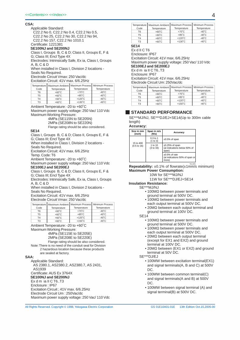
TemperatureCode
T6T5T4T3
Maximum AmbientTemperature
+60˚C+60˚C+60˚C+60˚C
Maximum ProcessTemperature
+70˚C+85˚C
+120˚C+130˚C
Minimum ProcessTemperature
-40˚C-40˚C-40˚C-40˚C
SE14Ex d II C T6Enclosure: IP67Excitation Circuit: 41V max. 6/6.25HzMaximum power supply voltage: 250 Vac/ 110 Vdc
SE100EJ and SE200EJEx d m ia II C T6..T3Enclosure: IP67Excitation Circuit: 41V max. 6/6.25HzElectrode Circuit Um: 250Vac/dcTemperature
CodeT6T5T4T3
Maximum AmbientTemperature
+60˚C+60˚C+60˚C+60˚C
Maximum ProcessTemperature
+70˚C+85˚C
+120˚C+150˚C
Minimum ProcessTemperature
-40˚C-40˚C-40˚C-40˚C
STANDARD PERFORMANCESE***MJ/NJ, SE***DJ/EJ+SE14(Up to 300m cablelength)Accuracy:
Size in mm (inch)
Span in m/s (ft/s)
Accuracy
15 to 400(0.5 to 16)
0.3 to 1(1 to 3)
±0.5% of span
1 to 10(3 to 33)
±0.25% of span(at indications below 50% of span)
±0.5% of rate(at indications 50% of span or more)
T01.EPS
Repeatability: ±0.1% of flowrate(±1mm/s minimum)Maximum Power Consumption:
10W for SE***MJ/NJ11W for SE***DJ/EJ+SE14
Insulation Resistance:SE***MJ/NJ
• 100MΩ between power terminals andground terminal at 500V DC.
• 100MΩ between power terminals andeach output terminal at 500V DC.
• 20MΩ between each output terminal andground terminal at 100V DC.
SE14• 100MΩ between power terminals and
ground terminal at 500V DC.• 100MΩ between power terminals and
each output terminal at 500V DC.• 20MΩ between each output terminal
(except for EX1 and EX2) and groundterminal at 100V DC.
• 20MΩ between (EX1 or EX2) and groundterminal at 50V DC.
SE***DJ/EJ• 100MW between excitation terminal(EX1)
and signal terminals(A, B and C) at 500VDC.
• 100MW between common terminal(C)and signal terminals(A and B) at 500VDC.
• 100MW between signal terminal (A) andsignal terminal(B) at 500V DC.
CSA:Applicable Standard:
C22.2 No 0, C22.2 No 0.4, C22.2 No 0.5,C22.2 No 25, C22.2 No 30, C22.2 No 94,C22.2 No 157, C22.2 No 1010.1
Certificate: 1221381 SE100NJ and SE200NJ
Class I, Groups B, C & D; Class II, Groups E, F &G; Class III; Encl Type 4XElectrodes: Intrinsically Safe, Ex ia, Class I, GroupsA, B, C & DWhen installed in Class I, Division 2 locations -Seals No Required.Electrode Circuit Vmax: 250 Vac/dcExcitation Circuit: 41V max. 6/6.25HzTemperature
CodeT6T5T4T3
Maximum AmbientTemperature
+60˚C+60˚C+60˚C+60˚C
Maximum ProcessTemperature
+70˚C+85˚C+120˚C+130˚C
Minimum ProcessTemperature
-40˚C-40˚C-40˚C-40˚C
Ambient Temperature: -20 to +60˚CMaximum power supply voltage: 250 Vac/ 110 VdcMaximum Working Pressure:
4MPa (SE115N to SE205N)2MPa (SE208N to SE220N)Flange rating should be also considered.
SE14Class I, Groups B, C & D; Class II, Groups E, F &G; Class III; Encl Type 4XWhen installed in Class I, Division 2 locations -Seals No Required.Excitation Circuit: 41V max. 6/6.25HzTemp. Code: T6Ambient Temperature: -20 to +60˚CMaximum power supply voltage: 250 Vac/ 110 Vdc
SE100EJ and SE200EJClass I, Groups B, C & D; Class II, Groups E, F &G; Class III; Encl Type 4XElectrodes: Intrinsically Safe, Ex ia, Class I, GroupsA, B, C & DWhen installed in Class I, Division 2 locations -Seals No Required.Excitation Circuit: 41V max. 6/6.25HzElectrode Circuit Vmax: 250 Vac/dcTemperature
CodeT6T5T4T3
Maximum AmbientTemperature
+60˚C+60˚C+60˚C+60˚C
Maximum ProcessTemperature
+70˚C+85˚C+120˚C+150˚C
Minimum ProcessTemperature
-40˚C-40˚C-40˚C-40˚C
Ambient Temperature: -20 to +60˚CMaximum Working Pressure:
4MPa (SE115E to SE205E)2MPa (SE208E to SE220E)Flange rating should be also considered.
Note: There is no need of the conduit seal for Division2 hazardous location because these productsare sealed at factory.
SAA:Applicable Standard:
AS 2380.1, AS2380.2, AS2380.7, AS 2431,AS1939
Certificate: AUS Ex 3764X SE100NJ and SE200NJ
Ex d m ia II C T6..T3Enclosure : IP67Excitation Circuit ; 41V max. 6/6.25HzElectrode Circuit Um : 250Vac/dcMaximum power supply voltage: 250 Vac/ 110 Vdc
13th Edition Oct.15,2005-00

5<<Contents>> <<Index>>
All Rights Reserved. Copyright © 1998, Yokogawa Electric Corporation GS 01E10A01-01E
Withstand Voltage:SE***MJ/NJ; SE14
• 1500V AC between power terminals andground terminal for 1 minute. (for -A1/A2power supply)
• 500V AC between power terminals andground terminal for 1 minute. (for -D1power supply)
SE***DJ/NJ• 1000V AC between excitation terminals
(EX1 and EX2) and ground terminal(G)for 1 minute.
• 500V AC between signal terminals(A andB) and ground terminal(G) for 1minute.(for /KF2, /FF1)
• 2000V AC between signal terminals(Aand B) and excitation terminals(EX1 andEX2) for 1 minute. (for /KF2, /FF1)
Safety Requirement Standard:IEC1010, EN61010
EMC Conformity Standard:EN61326EN61000-3-2, EN61000-3-3AS/NZS CISPR 11
Pressure Equipment Directive:Notified Body Identification Number 0038Module: H
MODELSE115
SE202
SE204SE205SE208SE210SE215SE220SE325SE330SE335SE340
DN(mm)*15
25
405080
100150200250300350400
PS(MPa)*4
4
4422222211
CATEGORY** Article 3, ***
paragraph 3 Article 3, ***
paragraph 3
IIIIIIIIIIIIIIIIIIIIIIII
PS-DN(MPa-mm)60
100
160200160200300400500600350400
* PS: Maximum allowable pressure for Flow Tube, DN: Noinal size
** Referred to Table 6 covered by ANNEX II of EC Directive on Pressure
Equipment Directive 97/23/EC.
***SE115 and SE202 are not attached CE mark of PED because they do not
come under CE marking of PED.
NORMAL OPERATING CONDITIONAmbient Temperature: -20 to 60 °C (-4 to 140 °F)
Note : The minimum temperature is -10C (14F) incase of the 40mm or lager sizes with the carbonsteel flange connection or wafer connection.
Ambient Humidity: 5 to 95%RH (no condensation)Rated Power Supply Voltage:
100V AC/DC Version: Range 80 to 127V AC, 47 to 63Hz
90 to 110V DC230V AC Version Range 180 to 264V AC24V DC/AC Version : Range 20.4 to 28.8 V DC/AC
Supplied Power and Max. Cable Length for 24VDC version:
Allowable cable length m(ft)1000(3300)
900(2970)800(2640)700(2310)600(1980)500(1650)400(1320)
300(990)200(660)100(330)
020 22 24 26 28 (V)
Cable cross section area: 1.25 mm2
Cable cross section area: 2 mm2F01.EPS
Altitude at installation side: Max.2000m above sea level
Installation category based on IEC1010:II(See Note)
Pollution level based on IEC1010: 2(See Note)Note: • The “Installation category” implies the regulation
for impulse withstand voltage. It is also called the“Overvoltage category”.“II” applies to electricalequipment.
• “Pollution level” describes the degree to which asolid, liquid or gas which deteriorates dielectricstrength is adhering. “2” applies to a normalindoor atmosphere.
Fuse: 2A 250V (Time-Lag type)Fluid Conductivity: 5µS/cm or larger*In case that size 250 or 300mm is used for high conductivityfluid (ex. caustic soda, seawater), please use the flange type.
Measurable Flow Rate Range:
MIN. [email protected]/s
MAX. Range@10m/s
1525405080
100150200250300350400
0.19090.53021.35722.1206
5.4298.483
19.08633.9353.0276.35
103.91135.72
Size
6.36117.671
45.2370.68
180.95282.74
636.11,130.91,767.12,544.6
3,4634,523
SI Units (Size : mm, Flowrate : m3/h)
MIN. [email protected]/s
MAX. Range@33ft/s
0.51
1.523468
10121416
0.60242.4095
5.4229.638
21.68538.5686.74
154.21240.95
347.0472.3616.9
T02.EPS
Size
20.07880.31
180.70321.2722.8
1,285.02,891.3
51408031
11,56515,74120,560
English Units (Size : inch, Flowrate : GPM)
13th Edition Oct.15,2005-00

6
All Rights Reserved. Copyright © 1998, Yokogawa Electric Corporation
<<Contents>> <<Index>>
GS 01E10A01-01E
Fluid Temperature and Pressure:
Integral type SE***MJ/NJ
2(20)(285
4(40)570
1(10)142
-0.1(-1)-14.2
PressureMPa(kgf/cm2)psi
-40(-40)
0(32)
-10(14)
40(104)
130(266)
100(212)
Temperature °C(°F)F02-1.EPS
Size 15 mm(0.5in.) to 50 mm(2in.)Size 80 mm(3in.) to 200 mm(8in.)
Remote type SE***DJ/EJ
Temperature °C (°F)
PressureMPakgf/cm2[psi]
Size 15mm (0.5in.) to 50mm (2in.)Size 80mm (3in.) to 300mm (12in.)Size 350mm (14in.) and 400mm (16in.)
440[570]
220[285]
110[142]
-0.1-1[-14.2]-40
(-40)0
(32)-10(14)
100(212)
40(104)
130(266)
160(320)
F02-2.EPS
Note 1: The above limits show maximum allowable fluid pressure for Flow Tube itself. Further fluid pressure should also be limitted according to flange rating.
Note 2: The minimum temperature is -10C (14F) in case of the 40mm or lager sizes with the carbon steel flange connection or wafer connection.
13th Edition Oct.15,2005-00
TERMINAL CONNECTIONIntegral type flowmeter(SE***MJ/NJ):
Terminal Symbols Description
GPOWER N-POWER L+
CUR+CUR-
PLS/ALM+PLS/ALM-
Ground and power supply
Current output 4 to 20 mA DC
Pulse, alarm or status output
T03-3.EPS
Protective grounding
Remote type converter(SE14):TerminalSymbols
Description
SAAB
SBC
EX1EX2P+P-I+I-
L/+N/-G
Flow signal input
T03-1.EPS
Protective grounding
A shield
Current output 4 to 20mA DC
Excitation current output
B shieldCommon
Pulse, alarm or status output
Power supply and Ground
PLS/ALM OUT
CUROUT
POWER SUPPLY
Remote type flow tube(SE***DJ/EJ):TerminalSymbols
Description
ABC
EX1EX2
Common
Excitation current inputFunction grounding (Outside of the Terminal box)
Flow signal output
T03-2.EPS

7<<Contents>> <<Index>>
All Rights Reserved. Copyright © 1998, Yokogawa Electric Corporation GS 01E10A01-01E
MODEL AND SUFFIX CODEIntegral Type Magnetic Flowmeter:
SE115SE202SE204SE205SE208SE210SE215SE220
M . . . . . . . . . . . . . . . . . . . . . . . . . . . N . . . . . . . . . . . . . . . . . . . . . . . . . . .
J . . . . . . . . . . . . . . . . . . . . . . . . . .
-D . . . . . . . . . . . . . . . . . . . . . . . -E . . . . . . . . . . . . . . . . . . . . . . . .
A . . . . . . . . . . . . . . . . . . . . .
B1S . . . . . . . . . . . . . . . B2S . . . . . . . . . . . . . . . E1S . . . . . . . . . . . . . . . E2S . . . . . . . . . . . . . . . E4S . . . . . . . . . . . . . . . K1S . . . . . . . . . . . . . . . K2S . . . . . . . . . . . . . . . A1C . . . . . . . . . . . . . . . A2C . . . . . . . . . . . . . . . D1C . . . . . . . . . . . . . . . D2C . . . . . . . . . . . . . . . D4C . . . . . . . . . . . . . . . J1C . . . . . . . . . . . . . . . J2C . . . . . . . . . . . . . . . G1C . . . . . . . . . . . . . . . A1S . . . . . . . . . . . . . . . A2S . . . . . . . . . . . . . . . D1S . . . . . . . . . . . . . . . D2S . . . . . . . . . . . . . . . D4S . . . . . . . . . . . . . . . J1S . . . . . . . . . . . . . . . . J2S . . . . . . . . . . . . . . . . G1S . . . . . . . . . . . . . . .
-L . . . . . . . . . . . . . -P . . . . . . . . . . . . . -H . . . . . . . . . . . . . -T . . . . . . . . . . . . . -V . . . . . . . . . . . . . -W . . . . . . . . . . . .
N . . . . . . . . . . S . . . . . . . . . . P . . . . . . . . . . H . . . . . . . . . . T . . . . . . . . . . V . . . . . . . . . .
0 . . . . . . . . . . 2 . . . . . . . . . 3 . . . . . . . . . 4 . . . . . . . . .
-A1 . . . . . -A2 . . . . . -D1 . . . . .
NN . . H1 . . H2 . . V1 . . V2 . .
/
Suffix CodeModel Description
Construc-tion
Aux. Code
Output Signal
Lining (Note 3)
Process Connection
Electrode Material(Note 3)
Earth ring and Earth electrode Material(Note 3)
Electrical Connection
Power Supply
Indicator
HI, H2 V1, V2 NN
T04.EPS
. . . . . . . . . . . . . . . . . . . . . . . . .
. . . . . . . . . . . . . . . . . . . . . . . . .
. . . . . . . . . . . . . . . . . . . . . . . . .
. . . . . . . . . . . . . . . . . . . . . . . . .
. . . . . . . . . . . . . . . . . . . . . . . . .
. . . . . . . . . . . . . . . . . . . . . . . . .
. . . . . . . . . . . . . . . . . . . . . . . . .
. . . . . . . . . . . . . . . . . . . . . . . . .
Optional Code
(Refer to Note2)
Nominal Size 15 mm (1/2in.)Nominal Size 25 mm (1in.)Nominal Size 40 mm (1 1/2in.)Nominal Size 50 mm (2in.)Nominal Size 80 mm (3in.)Nominal Size 100 mm (4in.)Nominal Size 150 mm (6in.)Nominal Size 200 mm (8in.)Integral type for General PurposeIntegral type for Explosion Proof
Always J4-20 mA and Pulse or Alarm, Simultaneous 2-output (BRAIN)4-20 mA and Pulse or Alarm, Simultaneous 2-output (HART)
Fluorocarbon PFA
ANSI 150 WaferANSI 300 WaferDIN PN10 Wafer Only for 200 mm (Note 1)DIN PN16 Wafer Only for 80 to 200 mm (Note 1)DIN PN40 Wafer Only for 15 to 50 mm (Note 1)JIS 10K WaferJIS 20K WaferANSI 150 Flange Carbon Steel (SS400)ANSI 300 Flange Carbon Steel (SS400)DIN PN10 Flange Carbon Steel (SS400), Only for 200 mm (Note 1)DIN PN16 Flange Carbon Steel (SS400), Only for 80 to 200 mm (Note 1)DIN PN40 Flange Carbon Steel (SS400), Only for 15 to 50 mm (Note 1)JIS 10K Flange Carbon Steel (SS400)JIS 20K Flange Carbon Steel (SS400)JIS F12 Flange Carbon Steel (SS400), Only for 80 to 200 mmANSI 150 Flange Stainless Steel (SUS304)ANSI 300 Flange Stainless Steel (SUS304)DIN PN10 Flange Stainless Steel (SUS304), Only for 200 mm (Note 1)DIN PN16 Flange Stainless Steel (SUS304), Only for 80 to 200 mm (Note 1)DIN PN40 Flange Stainless Steel (SUS304), Only for 15 to 50 mm (Note 1)JIS 10K Flange Stainless Steel (SUS304)JIS 20K Flange Stainless Steel (SUS304)JIS F12 Flange Stainless Steel (SUS304), Only for 80 to 200 mm
Stainless Steel (SUS316L)Platinum-iridumHastelloy C276 EquivalentTantalumTitaniumTungsten CarbideNon Earth RingStainless Steel (SUS316)Platinum-iridum Electrode Hastelloy C276 EquivalentTantalum ElectrodeTitanium
JIS G1/2 FemaleANSI 1/2NPT FemaleDIN Pg13.5 FemaleISO M20X1.5 Female80 to 127 V AC/90 to 110 V DC180 to 264 V AC20.4 to 28.8 V DC/ACNon IndicatorWith Horizontal IndicatorWith Horizontal Indicator and Setting SWWith Vertical IndicatorWith Vertical Indicator and Setting SW
Note 1: Select PN40 when PN10, PN16, PN25 is required for 15 to 50mm, and select PN16 when PN10 is required for 80 to 150mm,because of same mating dimensions.
Note 2: Only ANSI1/2NPT electrical connection is available for FM or CSA explosion proof type. JIS G1/2 electrical connection is not available for any explosion proof type.
Note 3: Users must consider the characteristics of selected wetted parts material and the influence of process fluids. The use of inappropriate materials can result in the leakage of corrosive process fluids and cause injury to personnel and/or damage to plant facilities. It is also possible that the instrument itself can be damaged and that fragments from the instrument can contaminate the user's process fluids. Be very careful with highly corrosive process fluids such as hydrochloric acid, sulfuric acid, hydrogen sulfide, sodium hypochlorite, and high-temperature steam (150°C [302°F] or above). Contact Yokogawa for detailed information of the wetted parts material.
13th Edition Oct.15,2005-00
8
All Rights Reserved. Copyright © 1998, Yokogawa Electric Corporation
<<Contents>> <<Index>>
GS 01E10A01-01E
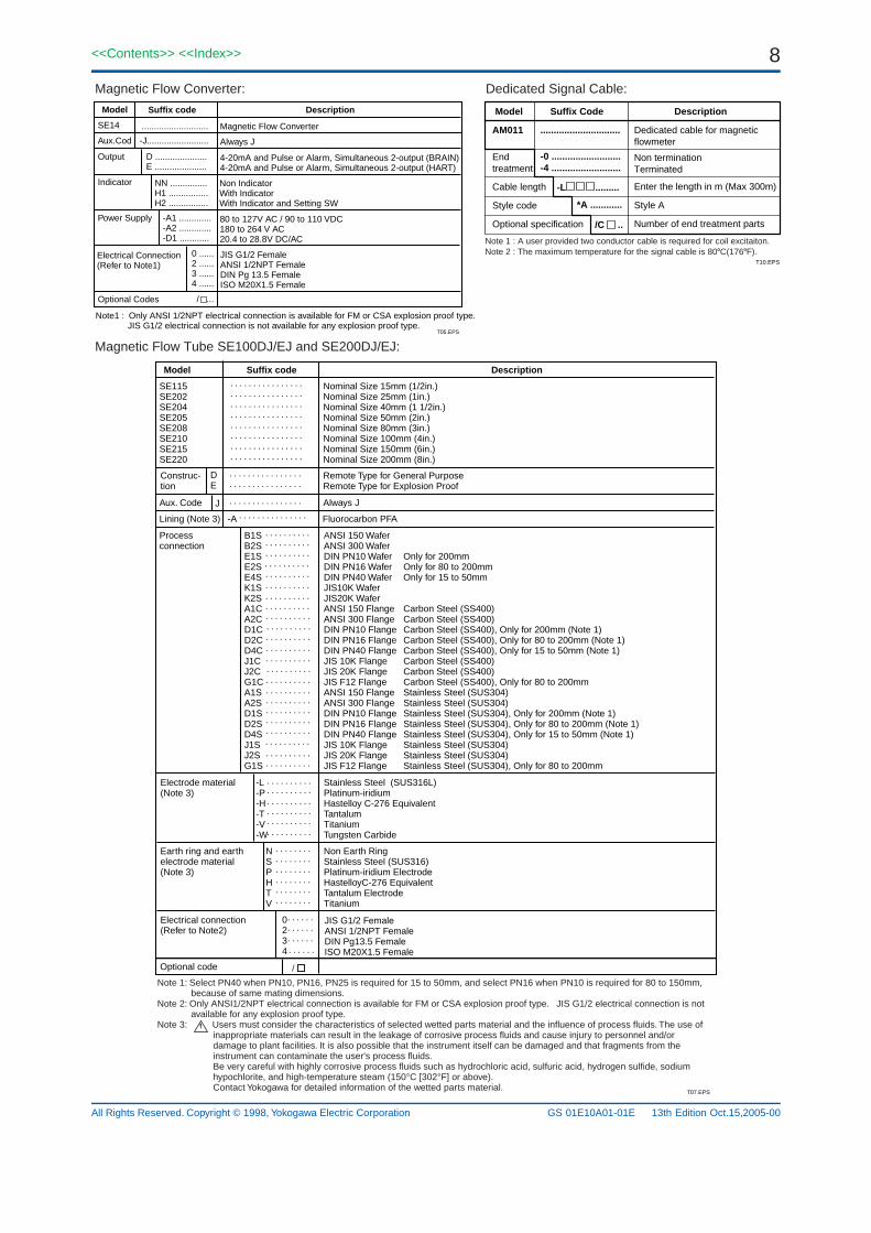
Magnetic Flow Converter: Dedicated Signal Cable:
T05.EPS
Model Suffix code Description
SE14 Magnetic Flow Converter
Aux.Cod -J......................... Always J
Output D .....................E .....................
4-20mA and Pulse or Alarm, Simultaneous 2-output (BRAIN)4-20mA and Pulse or Alarm, Simultaneous 2-output (HART)
Indicator NN ...............H1 ................H2 ................
Non IndicatorWith IndicatorWith Indicator and Setting SW
Power Supply -A1 .............-A2 .............-D1 ............
80 to 127V AC / 90 to 110 VDC180 to 264 V AC20.4 to 28.8V DC/AC
Electrical Connection(Refer to Note1)
0 ......2 ......3 ......4 ......
/ ...
JIS G1/2 FemaleANSI 1/2NPT FemaleDIN Pg 13.5 FemaleISO M20X1.5 Female
Optional Codes
...........................
Note1 : Only ANSI 1/2NPT electrical connection is available for FM or CSA explosion proof type. JIS G1/2 electrical connection is not available for any explosion proof type.
Model Suffix Code Description
AM011 ..............................
-0 ..........................-4 ..........................
Dedicated cable for magneticflowmeter
Non terminationTerminated
Enter the length in m (Max 300m)
Style A
Number of end treatment parts
-L .........
*A ............
/C ..
Endtreatment
Cable length
Style code
Optional specification
T10.EPS
Note 1 : A user provided two conductor cable is required for coil excitaiton.Note 2 : The maximum temperature for the signal cable is 80C(176F).
Magnetic Flow Tube SE100DJ/EJ and SE200DJ/EJ:
T07.EPS
Model Suffix code Description
SE115SE202SE204SE205SE208SE210SE215SE220
Nominal Size 15mm (1/2in.)Nominal Size 25mm (1in.)Nominal Size 40mm (1 1/2in.)Nominal Size 50mm (2in.)Nominal Size 80mm (3in.)Nominal Size 100mm (4in.)Nominal Size 150mm (6in.)Nominal Size 200mm (8in.)
Construc-tion
DE
Remote Type for General PurposeRemote Type for Explosion Proof
Aux. Code J Always J
Lining (Note 3) -A Fluorocarbon PFA
Process connection
Electrode material(Note 3)
Earth ring and earth electrode material(Note 3)
Electrical connection(Refer to Note2)
0234
-L -P -H -T -V -W
N S P H T V
Stainless Steel (SUS316L)Platinum-iridiumHastelloy C-276 EquivalentTantalumTitaniumTungsten Carbide
Non Earth RingStainless Steel (SUS316)Platinum-iridium ElectrodeHastelloyC-276 EquivalentTantalum ElectrodeTitanium
JIS G1/2 FemaleANSI 1/2NPT FemaleDIN Pg13.5 FemaleISO M20X1.5 Female
. . . . . . . . . . . . . . .
. . . . . . . . . . . . . . . .
. . . . . . . . . . . . . . . .
. . . . . . . . . . . . . . . .
. . . . . . . . . . . . . . . .
. . . . . . . . . . . . . . . .
. . . . . . . . . . . . . . . .
. . . . . . . . . . . . . . . .
. . . . . . . . . . . . . . . .
. . . . . . . . . . . . . . . .
. . . . . . . . . . . . . . . .
. . . . . . . . . . . . . . . .
. . . . . . . . . .
. . . . . . . . . .
. . . . . . . . . .
. . . . . . . . . .
. . . . . . . . . .
. . . . . . . . . .
. . . . . . . . . .
. . . . . . . . . .
. . . . . . . . . .
. . . . . . . . . .
. . . . . . . . . .
. . . . . . . . . .
. . . . . . . . . .
. . . . . . . . . .
. . . . . . . . . .
. . . . . . . . . .
. . . . . . . . . .
. . . . . . . . . .
. . . . . . . . . .
. . . . . . . . . .
. . . . . . . . . .
. . . . . . . . . .
. . . . . . . . . .
. . . . . . . . . .
. . . . . . . . . .
. . . . . . . . . .
. . . . . . . . . .
. . . . . . . . . .
. . . . . . . . . .
. . . . . . . .
. . . . . . . .
. . . . . . . .
. . . . . . . .
. . . . . . . .
. . . . . . . .
. . . . . .
. . . . . .
. . . . . .. . . . . .
Optional code /
B1S B2S E1S E2SE4S K1S K2S A1C A2C D1C D2C D4C J1C J2C G1C A1S A2SD1S D2S D4S J1S J2S G1S
ANSI 150 WaferANSI 300 WaferDIN PN10 Wafer Only for 200mmDIN PN16 Wafer Only for 80 to 200mmDIN PN40 Wafer Only for 15 to 50mmJIS10K WaferJIS20K WaferANSI 150 Flange Carbon Steel (SS400)ANSI 300 Flange Carbon Steel (SS400)DIN PN10 Flange Carbon Steel (SS400), Only for 200mm (Note 1)DIN PN16 Flange Carbon Steel (SS400), Only for 80 to 200mm (Note 1)DIN PN40 Flange Carbon Steel (SS400), Only for 15 to 50mm (Note 1)JIS 10K Flange Carbon Steel (SS400)JIS 20K Flange Carbon Steel (SS400)JIS F12 Flange Carbon Steel (SS400), Only for 80 to 200mmANSI 150 Flange Stainless Steel (SUS304)ANSI 300 Flange Stainless Steel (SUS304)DIN PN10 Flange Stainless Steel (SUS304), Only for 200mm (Note 1)DIN PN16 Flange Stainless Steel (SUS304), Only for 80 to 200mm (Note 1)DIN PN40 Flange Stainless Steel (SUS304), Only for 15 to 50mm (Note 1)JIS 10K Flange Stainless Steel (SUS304)JIS 20K Flange Stainless Steel (SUS304)JIS F12 Flange Stainless Steel (SUS304), Only for 80 to 200mm
Note 1: Select PN40 when PN10, PN16, PN25 is required for 15 to 50mm, and select PN16 when PN10 is required for 80 to 150mm,because of same mating dimensions.
Note 2: Only ANSI1/2NPT electrical connection is available for FM or CSA explosion proof type. JIS G1/2 electrical connection is not available for any explosion proof type.
Note 3: Users must consider the characteristics of selected wetted parts material and the influence of process fluids. The use of inappropriate materials can result in the leakage of corrosive process fluids and cause injury to personnel and/or damage to plant facilities. It is also possible that the instrument itself can be damaged and that fragments from the instrument can contaminate the user's process fluids. Be very careful with highly corrosive process fluids such as hydrochloric acid, sulfuric acid, hydrogen sulfide, sodium hypochlorite, and high-temperature steam (150°C [302°F] or above). Contact Yokogawa for detailed information of the wetted parts material.
13th Edition Oct.15,2005-00

9<<Contents>> <<Index>>
All Rights Reserved. Copyright © 1998, Yokogawa Electric Corporation GS 01E10A01-01E
Magnetic Flow Tube : SE300DJ
T08.EPS
Model Suffix code Description
SE325SE330SE335SE340
Nominal Size 250mm (10in.)Nominal Size 300mm (12in.)Nominal Size 350mm (14in.)Nominal Size 400mm (16in.)
Construc-tion
D Remote Type for General Purpose
Aux. Code J Always J
Lining (Note 1) -A Fluorocarbon PFA
Process connection
Electrode material(Note 1)
Earth ring material(Note 1)
Electrical connection 0234
-L -P -H-T-V-W
N S H V
Stainless Steel (SUS316L)Platinum-iridium Only for flange typeHastelloy C Equivalent Only for flange typeTantalum Only for flange typeTitanium Only for flange typeTungsten Carbide
JIS G1/2 FemaleANSI 1/2NPT FemaleDIN Pg13.5 FemaleISO M20X1.5 Female
. . . . . . . . . . . . . . .
. . . . . . . . . . . . . . . .
. . . . . . . . . . . . . . . .
. . . . . . . . . . . . . . . .
. . . . . . . . . . . . . . . .
. . . . . . . . . . . . . . . .
. . . . . . . . . . . . . . . .
. . . . . . . . .
. . . . . . . . .
. . . . . . . . .
. . . . . . . . .
. . . . . . .
. . . . . . . . . . . . . .
. . . . . . .
. . . . .
. . . . .
. . . . .
. . . . .
Non Earth RingStainless Steel (SUS316)Hastelloy C Equivalent Only for flange typeTitanium Only for flange type
Optional code /
. . . . . . . . . . . . . . . . . .
B1C . . . . . . . . . .E1C . . . . . . . . . .K1C . . . . . . . . . .H1C . . . . . . . . . .J1C . . . . . . . . . .J2C . . . . . . . . . .A1C . . . . . . . . . .A2C . . . . . . . . . .D1C . . . . . . . . . .D2C . . . . . . . . . .G1C . . . . . . . . . .J1S . . . . . . . . . .J2S . . . . . . . . . .A1S . . . . . . . . . A2S . . . . . . . . . .D1S . . . . . . . . . .D2S . . . . . . . . . .G1S . . . . . . . . . .
ANSI 150 Wafer Only for size 250 and 300mm (10 and12in.)DIN PN10 Wafer Only for size 250 and 300mm (10 and12in.)JIS 10K Wafer Only for size 250 and 300mm (10 and12in.)JIS F12 Wafer Only for size 250 and 300mm (10 and12in.)JIS 10K Flange Carbon Steel (SS400)JIS 20K Flange Carbon Steel (SS400), Only for size 250 and 300mm (10 and12in.)ANSI 150 Flange Carbon Steel (SS400)ANSI 300 Flange Carbon Steel (SS400), Only for size 250 and 300mm (10 and12in.)DIN PN10 Flange Carbon Steel (SS400)DIN PN16 Flange Carbon Steel (SS400), Only for size 250 and 300mm (10 and12in.)JIS F12 Flange Carbon Steel (SS400)JIS 10K Flange Stainless Steel (SUS304)JIS 20K Flange Stainless Steel (SUS304), Only for size 250 and 300mm (10 and12in.)ANSI 150 Flange Stainless Steel (SUS304)ANSI 300 Flange Stainless Steel (SUS304), Only for size 250 and 300mm (10 and12in.)DIN PN10 Flange Stainless Steel (SUS304)DIN PN16 Flange Stainless Steel (SUS304), Only for size 250 and 300mm (10 and12in.)JIS F12 Flange Stainless Steel (SUS304)
Note 1: Users must consider the characteristics of selected wetted parts material and the influence of process fluids. The use of inappropriate materials can result in the leakage of corrosive process fluids and cause injury to personnel and/or damage to plant facilities. It is also possible that the instrument itself can be damaged and that fragments from the instrument can contaminate the user's process fluids. Be very careful with highly corrosive process fluids such as hydrochloric acid, sulfuric acid, hydrogen sulfide, sodium hypochlorite, and high-temperature steam (150°C [302°F] or above). Contact Yokogawa for detailed information of the wetted parts material.
13th Edition Oct.15,2005-00

10
All Rights Reserved. Copyright © 1998, Yokogawa Electric Corporation
<<Contents>> <<Index>>
GS 01E10A01-01E
Optional Specifications :
Item Specification CodeEx-proof
Applicable Model
General
SE***EJSE14SE***DJSE***MJ SE14 SE***NJ
T09.EPS
A: Available N: Not available
Lightning Protector Built-in Lightning Protector A A N A A N /A
Waterproof Glands Waterproof glands are attached to all wiring ports. For JIS G1/2 only. A A A N N N /ECG
Painting Color Change Black, Munsell code : N1.5 A A A A A A /P1
Jade Green, Munsell code : 7.5BG4/1.5 A A A A A A /P2
Metallic Silver A A A A A A /P7
Level 2:Declaration and Calibration Equipment List A A A A A A /L2
Calibration Certificate Level 3:Declaration and Primary Standard List A A A A A A /L3
Level 4:Declaration and YOKOGAWA Measuring A A A A A A /L4
CENELEC ATEX(KEMA) Explosion Proof EExdm[ia]IICT6...T3;GroupII Category 2G N N N A N N /KF2
FM Explosion Proof Type Explosion Proof N N N A N A /FF1
CSA Explosion Proof Type Explosion proof N N N A N A /CF1
(Only for size 15 to 200mm) Explosion Proof/Nonincendive N N N N A N /FF1/FN1
(Only for size 15 to 200mm)
Explosion Proof Type Explosion Proof EExdIICT6;GroupII Category 2G N N N N A N
(Only for size 15 to 200mm) Explosion Proof EExdm[ia]IICT6...T3;GroupII Category 2G N N N N N A
SAA Explosion Proof Type Explosion Proof Exdm[ia]IICT6...T3 N N N A N N /SF1
(Only for size 15 to 200mm) Explosion Proof ExdIICT6 N N N N A N
Explosion Proof Exdm[ia]IICT6...T3 N N N N N A
Epoxy Coating Coating is changed to epoxy coating. A A A A A A /X1
Oil-prohibited Use Degreased cleansing treatment A N A A N A /K1
180 deg. Rotated Converter 180 deg. rotated converter for reversed flow direction A N N A N N /CRC
Material Certificate Reproduced material certificate for pipe, electrode, earth ring, mini-flange,and flange (depends on spec.). A N A A N A /M01
Hydrostatics Test Certificate With the following water pressure for 10min. The result is filled in Note columnof our standard certificate. JIS10K, ANSI Class 150, DIN PN10 : 1.5MPa,JIS20K, ANSI Class 300, DIN PN16 : 3.0MPa, JIS F12 : 1.25MPa A N A A N A /T01
Oil-prohibited Use with Dehydrating Treatment Degreased cleansing treatment and packed with desiccant A N A A N A /K5
High Anti-corrosion Coating Coating is changed to three-layer coating.(Urethane coating on two-layer Epoxy coating) A A A A A A /X2
Waterproof Glands Waterproof glands (uniont joints) are attached to all wiring ports. with Union Joints For JIS G1/2 only. A A A N N N /ECU
Bolt & Nut Assembly Stainless steel bolts/nuts and non-asbestos PTFE-wrapped gaskets assemblyfor wafer type Available with 15 to 200mm(0.5 to 8in.) A N A A N A /BSF
For District Heating and Cooling Condensation proof for DHC use. Only for size 100 to 400mm(For District Cooling) Terminal box; urethane resin potting. Wired 30m signal cable at factory. N N A N N N /DHC
DC Noise Suppression Eliminating DC Noise (Size 15mm(0.5in.) or larger: Conductivity 50S/cm or higher.) N A N N A N /ELC
Burn Out Down Current output at CPU failure is set to "Downward(2.4mA DC or less)".Without /C1 : Upward(21.6mA or more) A A N A A N /C1
Gaskets for PVC Pipe Gaskets are attached between earth ring and flow tube.(Note 1) Only for size 15 to 200mm A N A A N A /FRG
Note 1: Users must consider the characteristics of selected wetted parts material and the influence of process fluids. The use of inappropriate materials can result in the leakage of corrosive process fluids and cause injury to personnel and/or damage to plant facilities. It is also possible that the instrument itself can be damaged and that fragments from the instrument can contaminate the user's process fluids. Be very careful with highly corrosive process fluids such as hydrochloric acid, sulfuric acid, hydrogen sulfide, sodium hypochlorite, and high-temperature steam (150°C [302°F] or above). Contact Yokogawa for detailed information of the wetted parts material.
13th Edition Oct.15,2005-00

11<<Contents>> <<Index>>
All Rights Reserved. Copyright © 1998, Yokogawa Electric Corporation GS 01E10A01-01E
EXTERNAL DIMENSION
Model
Nominal size
LiningFace-to-facelengthOutsidediameterHeight
Weight kg(lb)*2
L*1
øD
H
H1
F03.EPS
15 mm (0.5 in) Wafer Type
25 mm (1 in) to 100 mm (4 in) Wafer Type
150 mm (6 in) to 200 mm (8 in) Wafer Type
Unit : mm(inch)
Lining : Fluorocarbon PFAWeight: 3.3kg(7.3 lb)With Indicator Option: Add 0.22kg(0.49lb)
When no earth ring is selected the face to face length is shorter by approx. 1.6 mm(0.06 in).
The face to face length is longer by approx. 22 mm(0.87 in) for earth ring(P,T).
The face to face length is longer by approx. 8.4mm(0.33 in) for optional code /FRG.
When no earth ring is selected the face to face length is shorter by approx. 1.6 mm(0.06 in).
The face to face length is longer by approx. 22 mm (0.87 in) for earth ring(P,T).
The face to face length is longer by approx.8.4mm (0.33 in) for optional code/FRG.
With Indicator
SE202J
25(1)
60(2.4)
67.5(2.7)
240(9.4)
84(3.3)
3.6(7.9)
SE204J
40(1.5)
70(2.8)
86(3.4)
260(10.2)
104(4.1)
3.8(8.3)
SE205J
50(2)
Fluorocarbon PFA
80(3.1)
99(3.9)
285(11.2)
129(5.1)
4.2(9.1)
SE208J
80(3)
120(4.7)
129(5.1)
307(12.1)
156(6.1)
6.6(14.6)
SE210J
100(4)
150(5.9)
155(6.1)
338(13.3)
182(7.2)
8.6(19.0)
*2 With Indicator Option: Add 0.22 kg(0.49 lb)
Model
Nominal size
LiningFace-to-facelengthOutsidediameterHeight
Weight kg(lb)*2
L*1
øD
H
H1
When no earth ring is selected the face to face length is shorter by approx. 2 mm (0.08 in).
The face to face length is longer by approx. 32 mm (1.3 in) for earth ring(P,T).
The face to face length is longer by approx. 10.0mm (0.40in) for optional code/FRG.
SE215J
150(6)
200(7.9)
218(8.6)
407(16.0)
248(9.8)
16.1(35.5)
SE220J
200(8)
250(9.8)
268(10.6)
457(18.0)
298(11.7)
24.2(53.4)
*2 With Indicator Option: Add 0.22 kg(0.49 lb)
Fluorocarbon PFA
192(7.6)With Indicator182(7.2)Non Indicator
30(1.2)61(2.4) 61(2.4)
GroundTerminal
40(1.6)With Indicator30(1.2)Non Indicator
ø123(4.8)
44(1.7)
147(5.8)
49(1.9)
67(2.6)
137(5.4)
60.5(2.4)
60(2.4)*
293(11.5)
192(7.6)With Indicator 182(7.2)Non Indicator
30(1.2)
61(2.4) 61(2.4)
GroundTerminal
40(1.6)With Indicator30(1.2)Non Indicator
ø123(4.8)
øD
147(5.8)
49(1.9)
67(2.6)
H1
L*1
H
With Indicator
192(7.6)With Indicator 182(7.2)Non Indicator30
(1.2) 61(2.4) 61(2.4)
GroundTerminal
40(1.6)With Indicator30(1.2)Non Indicator
ø123(4.8)
øD
147(5.8)
49(1.9)
67(2.6)
H1
L*1
H
H1
With Indicator
*
*1
*1
13th Edition Oct.15,2005-00

12
All Rights Reserved. Copyright © 1998, Yokogawa Electric Corporation
<<Contents>> <<Index>>
GS 01E10A01-01E
When no earth ring is selected the face to face length is shorter by approx. 1.6 mm(0.06 in).
The face to face length is longer by approx. 22 mm (0.87 in) for earth ring(P,T).
The face to face length is longer by approx. 8.4 mm (0.33 in) for optional code/FRG.
The thickness(t) is longer by approx. 11 mm (0.43 in) for earth ring(P,T).
The thickness(t) is longer by approx. 4.2 mm (0.17 in) for optional code/FRG.
Model
Nominal size
Flange Type
Lining
Flange outside dial.
Pitch circle dia.
Number of holes
Dia. of holes
Thickness
Weight kg(lb)*3
øD
øC
N
øh
t*2
F04-1.EPS
15 mm (0.5 in) Flange Type
25 mm (1 in) to 50 mm (2 in) Flange Type
Unit : mm(inch)
When no earth ring is selected the face to face length is shorter by approx. 1.6 mm(0.06 in).
The face to face length is longer by approx. 22 mm (0.87 in) for earth ring(P,T).
The face to face length is longer by approx. 8.4 mm (0.33 in) for optional code/FRG.
The thickness(t) is longer by approx. 11 mm (0.43 in) for earth ring(P,T).
The thickness(t) is longer by approx. 4.2 mm (0.17 in) for optional code/FRG.
J1
95(3.7)70
(2.8)
15(0.6)15.8(0.6)4.9
(10.7)
J2
95(3.7)70
(2.8)
15(0.6)17.8(0.7)5.0
(11.1)
A1
88.9(3.5)60.5(2.4)
15.7(0.6)15
(0.6)4.6
(10.0)
SE115 J
15(0.5)
Fluorocarbon PFA
4
A2
95.3(3.8)66.5(2.6)
15.7(0.6)18
(0.7)5.0
(11.0)
D4
95(3.7)65
(2.6)
14(0.6)19.8(0.8)4.5
(9.9)
*3 With Indicator Option: Add 0.22 kg(0.49 lb)
192(7.6)With Indicator 182(7.2)Non Indicator
30(1.2) 61(2.4) 61(2.4)
GroundTerminal
40(1.6)With Indicator30(1.2)Non Indicator
WithIndicator
ø123(4.8)
øC
øD
N-øh
147(5.8)
67(2.6)
49(1.9)
137(5.4)
60.5(2.4)
200(7.9)*1
t*2 293(11.5)
192(7.6)With Indicator182(7.2)Non Indicator
30(1.2) 61(2.4) 61(2.4)
GroundTerminal
40(1.6)With Indicator30(1.2)Non Indicator
With Indicator
147(5.8)
øC øDN-øh
147(5.8)
67(2.6)
49(1.9)
H1
L*1t*2
H
Model
Nominal size
Flange Type
Lining
Face to face length (ISO)
Flange outside dia.
Height
Pitch circle dia.
Number of holes
Dia. of holes
Thickness
Bolt hole pitch
Weight kg(lb)*3
L*1
øD
H
H1
øC
N
øh
t*2
J1
125(4.9)272
(10.7)113(4.4)90
(3.5)
19(0.7)17
(0.7)45
6.0(13.0)
J2
125(4.9)272
(10.7)113(4.4)90
(3.5)
19(0.7)19
(0.7)45
6.3(13.9)
A1
108(4.3)264
(10.4)105(4.1)79.2(3.1)
15.7(0.6)17.2(0.7)45
5.3(11.7)
A2
124(4.9)272
(10.7)113(4.4)88.9(3.5)
19.1(0.7)20.7(0.8)45
6.5(14.3)
D4
115(4.5)267
(10.5)108(4.3)85
(3.3)
14(0.6)21
(0.8)45
6.3(13.9)
J1
140(5.5)290
(11.4)131(5.2)105(4.1)
19(0.7)19
(0.7)45
7.6(16.8)
J2
140(5.5)290
(11.4)131(5.2)105(4.1)
19(0.7)21
(0.8)45
7.9(17.4)
A1
127(5.0)284
(11.1)125(4.9)98.6(3.9)
15.7(0.6)20.5(0.8)45
7.2(15.9)
A2
155.4(6.1)298
(11.7)139(5.5)144.3(5.7)
22.4(0.9)23.5(0.9)45
9.5(20.9)
D4
150(5.9)295
(11.6)136(5.4)110(4.3)
18(0.7)21
(0.8)45
9.2(20.3)
J1
155(6.1)316
(12.4)157(6.2)120(4.7)
419
(0.7)19
(0.7)45
9.0(19.8)
J2
155(6.1)316
(12.4)157(6.2)120(4.7)
819
(0.7)21
(0.8)22.5
9.1(20.0)
A1
152.4(6.0)315
(12.4)156(6.1)120.7(4.8)
419.1(0.7)22.2(0.9)45
9.5(20.9)
A2
165.1(6.5)321
(12.6)162(6.4)127(5.0)
419.1(0.7)25.2(1.0)22.5
11.1(24.5)
D4
165(6.5)321
(12.6)162(6.4)125(4.9)
418
(0.7)23
(0.9)45
10.9(24.0)
SE202J
25(1)
Fluorocarbon PFA
200(7.9)
4
SE204J
40(1.5)
Fluorocarbon PFA
200(7.9)
4
SE205J
50(2)
Fluorocarbon PFA
200(7.9)
*3 With Indicator Option: Add 0.22 kg(0.49 lb)
*1
*2
*1
*2
13th Edition Oct.15,2005-00

13<<Contents>> <<Index>>
All Rights Reserved. Copyright © 1998, Yokogawa Electric Corporation GS 01E10A01-01E
80mm (3in) to 100mm (4in) Flange Type192(7.6)With Indicator 182(7.2)Non Indicator
30(1.2) 61(2.4) 61(2.4)
GroundTerminal
40(1.6)With Indicator30(1.2)Non Indicator
With Indicator
ø123(4.8)
øCøDN-øh
147(5.8)
67(2.6)
49(1.9)
H1
L*1
t *2
H
When no earth ring is selected the face to face length is shorter by approx. 1.6 mm(0.06 in).
The face to face length is longer by approx. 22 mm (0.87 in) for earth ring(P,T).
The face to face length is longer by approx. 0.84mm (0.33 in) for optional code/FRG.
The thickness(t) is longer by approx. 11 mm (0.43 in) for earth ring(P,T).
The thickness(t) is longer by approx. 0.42mm (0.17 in) for optional code/FRG.
Unit : mm(inch)
*1
*2
F05.EPS
Model
Nominal size
Flange Type
Lining
Face to face length (ISO)
Flange outside dia.
Height
Pitch circle dia.
Number of holes
Dia. of holes
Thickness
Bolt hole pitch
Weight kg(lb)*3
L*1
øD
H
H1
øC
N
øh
t*2
J1
185(7.3)338
(13.3)179(7.0)150(5.9)
19(0.7)21.8(0.9)22.5
11.7(25.8)
J2
200(7.9)346
(13.6)187(7.4)160(6.3)
23(0.9)25.8(1.0)22.5
15.6(34.3)
A1
190.5(7.5)341
(13.4)182(7.2)152.4(6.0)
19.1(0.7)27.7(0.7)45
16.3(35.9)
A2
209.6(8.3)351
(13.8)197(7.8)168.1(3.5)
22.4(0.9)32.2(1.3)22.5
17.6(38.8)
D4
200(7.9)346
(13.6)187(7.4)160(6.3)
18(0.7)23.8(0.9)22.5
13.6(29.9)
G1
211(8.3)351
(13.8)192(7.6)168(6.6)
19(0.7)21.8(0.9)45
14.0(30.9)
J1
210(8.3)369
(14.5)210(8.3)175(6.9)
19(0.7)21.8(0.9)22.5
13.7(30.2)
J2
255(8.9)376
(14.8)217(8.5)185(7.3)
23(0.9)27.8(1.1)22.5
17.6(38.7)
A1
228.6(9.1)378
(14.9)219(8.6)190.5(7.5)
19.1(0.7)27.7(1.1)22.5
18.3(40.3)
A2
254(10.0)391
(15.4)232(9.1)200.2(7.9)
22.4(0.9)34.8(1.4)22.5
24.8(54.7)
D2
220(8.7)374
(14.7)215(8.5)180(7.1)
18
(0.7)23.8(0.9)22.5
15.6(34.3)
G1
23.8(9.4)383
(15.1)224(8.8)195(7.7)
419
(0.7)21.8(0.9)45
26(57.3)
SE208J
80(3)
PFA Lining
200(7.9)
4
SE210J
100(4)
PFA Lining
250(9.8)
8
*3 With Indicator Option: Add 0.22 kg(0.49 lb)
488
150mm (6in) to 200mm (8in) Flange Type192(7.6)With Indicator182(7.2)Non Indicator
30(1.2) 61(2.4) 61(2.4)
GroundTerminal
40(1.6)With Indicator30(1.2)Non Indicator
With Indicator
ø123(4.8)
øCøD
N-øh
147(5.8)
67(2.6)
49(1.9)
H1
L*1
t*2
H
When no earth ring is selected the face to face length is shorter by approx. 2 mm (0.08 in).
The face to face length is longer by approx. 32 mm (1.3 in) for earth ring(P,T).
The face to face length is longer by approx. 10.0 mm (0.4 in) for optional code/FRG.
The thickness(t) is longer by approx. 16 mm (0.63 in) for earth ring(P,T).
The thickness(t) is longer by approx. 5.0 mm (0.20 in) for optional code/FRG.
*1
*2
F05-1.EPS
Model
Nominal size
Flange Type
Lining
Face to face length (ISO)
Flange outside dia.
Height
Pitch circle dia.
Number of holes
Dia. of holes
Thickness
Bolt hole pitch
Weight kg(lb)*3
L*1
øD
H
H1
øC
N
øh
t*2
J1
280(11.0)438
(17.2)279
(10.7)240(9.4)
23(0.9)27
(1.1)22.5
28(64.7)
J2
305(12.0)450.5(17.8)291.5(11.5)260
(10.2)
25(1.0)33
(1.3)15
35(77.2)
A1
279.4(11.0)437.7(17.2)278.7(11.0)240(9.5)
22.3(0.9)30.4(1.2)22.5
30(66.1)
A2
317.5(12.5)450.7(18.0)297.8(11.7)270
(10.6)
22.3(0.9)41.5(1.2)15
45(99.2)
D2
285(11.2)440.5(17.4)281.5(11.1)240(9.4)
22(0.9)27
(1.1)22.5
30(66.1)
G1
290(11.4)443
(17.4)284
(11.2)247(9.7)
19(0.7)27
(1.1)30
29(64.0)
J1
330(13.0)488
(19.2)329
(13.0)290
(11.4)
23(0.9)27
(1.1)15
39(86)
J2
350(13.8)498
(19.6)339
(13.3)305
(12.0)
25(1.0)35
(1.4)15
49(108)
A1
342..5(13.5)493.4(19.4)335.5(13.2)298.4(11.7)
22.3(0.9)49.4(1.9)22.5
46(101)
A2
381(15.0)513.5(20.2)354.5(14.0)330.2(13.0)
25.4(1.0)46.1(1.8)15
68(149.9)
D1
220(8.7)493
(14.4)334
(13.1)295
(11.6)
22
(0.9)29
(1.1)22.5
43(94.8)
G1
342(13.5)494
(19.4)335
(13.2)299
(11.8)
819
(0.7)29
(1.1)22.5
45(99.3)
SE215J
150(6)
PFA Lining
300(11.8)
8
SE220J
200(8)
PFA Lining
350(13.8)
12
*3 With Indicator Option: Add 0.22 kg(0.49 lb)
6812
D2
340(13.4)493
(14.4)334
(13.1)295
(11.6)
1222
(0.9)29
(1.1)15
44(97.0)
128 12 12 8 8
13th Edition Oct.15,2005-00

14
All Rights Reserved. Copyright © 1998, Yokogawa Electric Corporation
<<Contents>> <<Index>>
GS 01E10A01-01E
Magnetic Flow Tube Unit : mm (inch)
15mm (0.5in) Wafer Type
111 (4.4)
268
(106
)
48 (1.9)
80.5
(3.
2)13
7 (5
.4)
60.5
(2.
4)
60 (2.4)*1
20.5
(0.
8)68
(2.
7)
ø86 (3.4)
Ground Terminal
ø44
(1.
7)
Weight 1.9 kg (4.2 lb)
SD1d.eps
*1 When no earth ring is selected the face to face length is shorter by approx. 1.6mm (0.06in).
The face to face length is longer by approx. 22mm (0.87in) for earth ring(P,T).
The face to face length is longer by approx. 8.4mm(0.33in)for optional code /FRG.
(M4)
25mm (1in) to 100mm (4in) Wafer Type
Face to face length
Nominal Size
Model
(14.7)(11.3)(6.5)(5.5) (4.2)1.9
Unit : mm (Approx. inch)
100 (4)80 (3)50 (2)40 (1.5)25 (1)
6.75.12.92.5Weight kg (lb)
182 (7.2)151 (5.9)129 (5.1)104 (4.1)84 (3.3)
155 (6.1)129 (5.1)99 (3.9)86 (3.4)67.5 (2.7)
235 (9.3) 313 (12.3)282 (11.1)260 (10.2)215 (8.5)
150 (5.9)120 (4.7)80 (3.1)70 (2.8)60 (2.4)
SE202DJSE202EJ
H1
H
L*1
(M4)
68 (
2.7)
20.5
(8.
1)
H
H1
L*1
111 (4.4)
48 (1.9)
80.5
(3.
2)
Lining
Outside diameter
Height
Fluorocarbon PFA
ø86 (3.4)
(øD
)
øD
øD
Ground Terminal
SD2d.eps
*1 When no earth ring is selected the face to face lengthis shorter by approx. 1.6mm (0.06in).
The face to face length is longer by approx. 22mm (0.87in) for earth ring (P,T).
The face to face length is longer by approx. 8.4mm(0.33in)for optional code /FRG.
SE204DJSE204EJ
SE205DJSE205EJ
SE208DJSE208EJ
SE210DJSE210EJ
150mm (6in), 200mm (8in) Wafer Type
Unit : mm (Approx. inch)
Model
Nominal Size
Weight
Ground Terminal(M4)
L*1 250200
H
H1
SE215DJSE215EJ
150
SE220DJSE220EJ
200
14.5
248
379
298
429
218 268
22.5(32.0) (49.5) kg (lb)
H
H1
80.5
(3.
2)
48(1.9)111 (4.4)
20.5
(8.
1)68
(2.7
)
Lining
Height
(6) (8)
Outside diameter
Face to face length
(14.9)
(9.8)
(16.9)
(11.7)
(8.6) (10.6)
(7.9) (9.8)
Fluorocarbon PFA
øD
ø86 (3.4)
(øD
)
øD
SD3d.eps
*1 When no earth ring is selected the face to face length is shorter by approx. 2mm (0.08in). The face to face length is longer by approx. 32mm (1.3in) for earth ring(P,T).
The face to face length is longer by approx. 10.0mm(0.40in) for optional code /FRG.
L*1
13th Edition Oct.15,2005-00

15<<Contents>> <<Index>>
All Rights Reserved. Copyright © 1998, Yokogawa Electric Corporation GS 01E10A01-01E
250mm(10in), 300mm(12in) Wafer Type Unit : mm (inch)
SD3-2.eps
øD
Ground Terminal(M4)
111 (4.4)
80.5
(3.
2)
48(1.9)
20.5
(8.
1)68
(2.7
)
ø86 (3.4)
L*1
H
H1
(øD
)
Unit : mm (Approx. inch)Model
Nominal Size
Weight
L*1350300
H
H1
SE325DJ250
SE330DJ300
39
340
471
388
519
310 358
48.3(86.0) (106.5) kg (lb)
Lining
Height
(10) (12)
Outside diameter
Face to face length
(18.5)
(13.4)
(20.4)
(15.3)
(12.2) (14.1)
(11.8) (13.8)
Fluorocarbon PFA
øD
*1 : When no earth ring is selected, the face to face length is shorter by approx. 2mm (0.08in).
15mm (0.5in) Flange Type
Face to face length
(6.9)(8.0)(7.1)(8.0)(7.7)
200 (7.9)
(M4)
30.8292628.826.8T*2
3.13.63.23.63.5
15.8 17.8 15
66.560.57070
18
95 95 88.9 95.3
15 15 15.7 15.7
T*2
øh
95
19.8
65
14
J1 J2 A1 A2 D4
L*1268
(10.
6)
137
(5.4
)80
.5 (
3.2)
48 (1.9)
111 (4.4)
20.5
(0.
8)68
(2.
7)
L*1
T*2
60.5
(2.
4)
Unit : mm (Approx. inch)
(3.7)
(0.6)
(1.1)
(2.8)
(0.6)
(3.7)
(0.7)
(1.1)
(2.8)
(0.6)
(3.5)
(0.6)
(1.0)
(2.4)
(0.6)
(3.8)
(0.7)
(1.1)
(2.6)
(0.6)
(3.7)
(0.8)
(1.2)
(2.6)
(0.6)
Flange outside dia
Dia. of holes
Pitch circle dia.
Thickness (Except P.T Earthring)
Weight kg (lb)
Lining
Flange Type
Ground Terminal
Thickness (P.T Earthring)
Fluorocarbon PFA
Nominal size
Model SE115DJ , SE115EJ
15 (0.5)
4-øh
øD
øC
ø86 (3.4)
øC
øD
SD4d.eps
*1 When no earth ring is selected the face to face length is shorter by approx. 1.6mm (0.06in).The face to face length is longer by approx. 22mm (0.87in)for earth ring(P,T).The face to face length is longer by approx. 8.4mm (0.33in)for optional code/FRG.
*2 The thickness(T) is longer by approx. 4.2mm (0.17in)for optional code/FRG.
25mm (1in) to 50mm (2in) Flange Type
Ground Termimal
80.5
(3.
2)
48 (3.2)111 (4.4)
20.5
(0.
8)68
(2.
7)
H1
H2
H
L*1
T*2
SD5d.EPS
N-øhøC
øD
ø86 (3.4)
*1 When no earth ring is selected the face to face length is shorter by approx. 1.6mm (0.06in). The face to face length is longer by approx. 22mm (0.87in) for earth ring(P,T).
The face to face length is longer by approx. 8.4mm (0.33in) for optional code/FRG.*2 The thickness(T) is longer by approx. 4.2mm (0.17in) for optional code/FRG.
Unit : mm(Approx, inch)
Thickness (P,T Earth ring)
4.3 4.6 3.6 4.8 4.6 6.3 6.6 5.9 8.2 7.9 7.7 7.8 8.2 9.8 9.6(9.4) (10.1) (7.8) (10.5) (13.9)(14.5)(13.0)(18.1)(17.4)(17.0)(17.3)(18.1)(21.7)(21.2)
Flange Type
Height
Nominal Size
Model
Face to face length
Pitch circle dia.
Weight
3436.433.132303234.631.532303231.528.23028T*2
293
162
19.1
127
165.1
22.4
114.3
155.4
19.1
88.9
124
270
139113
244
J1 J2 A1 A2 D4J1 J2 A1 A2 D4
162156157136125131108105113
293287288267256262239236
H2
244
50 (2)
165
25.4
18
152.4
19.1
155
1918
23.6
150
15.7
127
19
140
40 (1.5)
1415.719
115108125
20.5
25 (1)
J2
øh
T*2
H1
H
A2A1J1
N
90 79.2 85 105 98.6 110
4
120 120.7 125
4 4 484
17.21917 20.52119 22.12119
D4
21 21 23
200 (7.9) 200 (7.9) 200 (7.9)L*1
806151
SE202DJ,SE202EJ
(lb)kg
(0.7) (0.6) (0.8) (0.6) (0.7) (0.6) (0.9) (0.7) (0.7) (0.7) (0.7) (0.7)
(3.5) (3.1) (3.5) (3.3) (4.1) (4.3)(3.9) (4.5)
(0.7) (0.8) (0.8)
(4.9)(5.0)(4.8)(4.7)
(1.1) (1.3) (1.1) (1.3)(1.1)
(0.7) (0.8) (0.8) (0.8)(0.7)
(1.4)
(0.9)
(1.3)
(0.8)
(6.1)(5.9)(6.1)(5.0)(5.5)(4.3) (4.5)(4.9)
(1.1)(1.2)
(0.9)(1.0)(0.9)
(1.3)(1.4)(1.3)(1.3)
(6.5)(6.5)(6.0)
(1.2)
(4.4)
(10.6)(10.1)(10.3)(9.6)(9.6)(9.3)(9.6)
(5.2)(4.3)(4.4)(4.1)
(11.5)(11.5)(11.3)(13.0)(10.5)
(6.4)(6.4)(6.1)(6.2)(5.4)(5.5)(4.9)
(4.9)
(0.7) (0.7)
(1.1)
(2.0) (2.4) (3.1)
Flange outside dia.
Dia. of holes
Number of holes
Thickness(Except P,T Earth ring)
øD
øC
(10.1)
Lining Fluorocarbon PFA Fluorocarbon PFA Fluorocarbon PFA
SE204DJ,SE204EJ SE205DJ,SE205EJ
Bolt hole pitch
45 45 454545454545 45 45 45 45 4522.5 22.5
(M4)
13th Edition Oct.15,2005-00

16
All Rights Reserved. Copyright © 1998, Yokogawa Electric Corporation
<<Contents>> <<Index>>
GS 01E10A01-01E
80mm(3in), 100mm(4in) Flange Type Unit : mm (inch)
Unit : mm (Approx. inch)
(53.0)(36.0)(34.5)(25.9)(27.6)(32.7)(31.1)(22.5) (35.5)(26.7) (50.4)(30.1)
ModelNominal SizeFlange Type
Height
Face to face length
Thickness (P , T Earth ring)
Thickness(Except P,T Earth ring)
Weight kg (lb)
T*2
L*1
5
(M4)
10587
224
359
19
195
238
348
217
225
23
185
341
210
210
19
175
318310
187179
48488
2319
160150
200185
232219192192182
363350323323313
24.1
H2
12.514.814.110.2 16.415.711.8
21.8
254
22.419.1
228.6
100 (4)
1922.419.1
211209.6190.5
21.8
80 (3)J1 J2 A1 A2 G1A2J2
T*2
H1
H
G1A1J1
N
152.4168.1 168 190.5200.2
8
32.227.725.821.8 34.827.727.821.8
200 (7.9) 250 (9.8)L*1
T*2 32.8 36.8 38.7 32.8 32.8 38.8 37.7 32.843.2 45.8
D2
346
215
D2
318
187
220
23.8
34.8
180
18
200
23.8
34.8
160
18
8 416.1 12.1 22.9 13.7
SE208DJ , SE208EJ SE210DJ , SE210EJ
H2 H
H1
80.5
(3.2
)
48(1.9)
111(4.4)
20.5
(0.8
)68
(2.7
)
Lining
(7.3) (7.9)
(7.4) (7.5)
(8.6)(8.3)(8.3)(7.9)(8.3)(7.5)
(8.5)(8.3)(7.0) (7.4) (7.2) (7.6)
(8.7)(1.0)(9.0)
(12.5)(12.2) (12.5) (12.7)(12.3)(12.7)
(8.5) (8.8)(8.6) (9.1)
(13.7)(13.4) (13.6) (14.1)(13.8)(14.3)
(5.9) (6.3) (6.6)(6.3)(6.6)(6.0)
(1.3) (1.5) (1.3)(1.4)(1.8)(1.5)
(0.9) (1.0) (0.9)(0.9)(1.3)(1.1)
(6.9) (7.3) (7.7)(7.1)(7.9)(7.5)
(0.9) (1.1) (0.9)(0.9)(1.4)(1.1)
(1.3) (1.4) (1.3)(1.4)(1.7)(1.5)
(0.7) (0.9) (0.7)(0.7)(0.9)(0.8)(0.7) (0.9) (0.7)(0.7)(0.9)(0.8)
(9.4)Flange outside dia.
Pitch circle dia.
Dia. of holes
Number of holes
Fluorocarbon PFA Fluorocarbon PFA
N-øh
øD
øC
Ground Terminal
ø86(3.4)
øD
øC
øh
*1 When no earth ring is selected the face to face length is shorter by approx. 1.6mm (0.06 in).
The face to face length is longer by approx. 22mm (0.87in) for earth ring(P,T).
The face to face length is longer by approx. 8.4mm (0.33in) for optional code/FRG.
*2 The thickness(T) is longer by approx. 4.2mm(0.17in) foroptional code/FRG.
(3.4) (4.1)
SD6d.eps
Bolt hole pitch 22.5 22.5 22.5 22.5 22.5 22.5 22.5 22.5 22.5 454545
150mm(6in), 200mm(8in) Flange Type
Unit : mm (Approx : inch)
Ground Terminal
80.5
(3.2
)
48 (1.9)
ø86 (3.4)
111 (4.4)
20.5
(0.
8)68
(2.7
)
H1
H2
L*1
T*2
H
øC
øD
N-øh
SD7d.eps(58.3) (73.7) (62.7) (82.1) (114.2) (104.2) (90.9) (93.1)(95.7) (62.7) (146.1)(60.5) (95.3)
Model
Nominal Size
Flange Type
Height
Thickness (Except P,T Earth ring)
Weight
164139H2
L*1 350 (13.8)300 (11.8)
27 35 49.4 46.127 33 30.4 41.5
12
330.2298.4269.7241.3øC
N
J1 A1
H
H1
øD
T*2
J2 A2 D1A2A1J2J1
SE215DJ , SE215EJ
150 (6)
279.4 317.5
22.3 22.3
SE220DJ , SE220EJ
200 (8)
342.9
22.3 25.4
381
29
37.3 47.3 44.326.4 33.4 28.4 41.3
409.7 428.7 466.4 485.5
278.7 297.8 335.5 354.5
280 305
240 260
23 25
8 12 8 12
279 291.5
410 422.5
290
23
330
329
460
305
25
350
339
470
340
295
22
465
334
D2
465
334
340
29
295
22
42.3
12 8 8 12
43.4 28.4
D2
412.5
281.5
285
27
240
22
8
66.3
12
T*243 49 46.4 57.5 43 43 51 52.4 62.1 45 45
G1
415
284
290
27
43
247
19
6
27.4
G1
466
335
342
29
45
299
19
8
43.3kg (lb)
(16.1)
(11.1)
(16.6) (16.1) (16.9)
(11.2)
(16.2) (16.3) (18.3)
(11.7)
(18.3)
(13.1)
(18.3)
(14.0)
(19.1)
(13.2)
(18.4)(18.5)
(13.3)(12.6)
(18.1)
(13.1) (13.2)
(13.5)
(1.1)(1.1)(1.1)(1.8)
(13.4)(15.0)(13.5)(13.8)(13.0)
(1.7) (2.0) (2.1)
(1.1) (1.9)(1.4)
(13.4)
(11.7) (11.8)(11.6)(11.6)(13.0)
(1.8)(1.8)(1.8)(2.4)
(0.9) (1.0) (0.7)(0.9)(0.9)(1.0)(0.9)
(1.1) (12.0)
(14.8) (11.2) (11.0)
(1.1)
(1.7)
(9.7)
(0.7)
(1.9)(1.7)
(11.0) (12.0) (11.0)
(1.2) (1.1)(1.6)
(10.2) (9.5) (10.6) (9.4)
(1.7)(2.3)(1.8)
(1.3)(1.1)
(9.4)
(0.9) (0.9)(0.9)(0.9)(1.0)
(11.0)(11.5)(11.0)
Lining Fluorocarbon PFA
Face to face length (ISO)
Outside diameter
Pitch circle dia.
Dia. of holes
Number of holes
(6.5)(5.5)
Fluorocarbon PFA
Thickness (P,T Earth ring)
øh
*1 When no earth ring is selected the face to face length is shorter by approx. 2mm (0.08in). The face to face length is longer by approx. 32mm (1.3in) for earth ring(P,T). The face to face length is longer by approx. 10.0mm (0.40in) for optional code/FRG.
*2 The thickness(T) is longer by approx. 5.0mm (0.20in) for optional code/FRG.
Bolt hole pitch 22.5 22.5 30 15 22.5 15 15 22.515 22.522.51515
(M4)
13th Edition Oct.15,2005-00

17<<Contents>> <<Index>>
All Rights Reserved. Copyright © 1998, Yokogawa Electric Corporation GS 01E10A01-01E
250mm(10in) to 400mm(16in) Flange Type Unit : mm (inch)
L*1
T*2
Ground TerminalEye Bolt
(M4)H
1
H2
48(1.9)
86(3.4)ø
H
111(4.4)
111(
4.4)
50.5
(2)
øhN-
øC
ød
øD
*1 When no earth ring is selected the face to face length is shorter by approx. 26mm (1.02 inch) for 250mm(10 inch), 6mm (0.23 inch) for 300mm (12 inch), 10mm (0.4 inch) for 350mm (14 inch) and 400mm (16 inch).
Unit : mm(approx : inch)
(167.6) (156.6) (154.4) (154.4)
Model
Nominal Size
Eye bolt
(161) (211.7) (229.3) (191.8) (194) (191.8) (191.8) (200.7) (271.2) (235.9) (235.9) (235.9) (348.4) (297.7) (297.7) (297.7)
SIZE/ød
H2
M12 / 30
355(14)
350(13.8)øC
N
A1 D1
H
H1
øD
øh
A2 D2
SE325
250(10)
395(15.5)
405(16)
22(0.9)
26(1)
SE330
300(12)
76 81(178.6)
70(154.4)
516.7(20.3)
521.7(20.5)
449.2(17.7)
459.2(18.1)
406.4(16)
444.5(17.5)
361.9(14.2)
387.3(15.2)
25.4(1)
28.4(1.1)
12 16 12 12
460.6(18.1)
498.7(19.6)
522.4(20.6)
541.5(21.3)
71 70
G1
524.2(20.6)464.2(18.3)
410(16.1)
360(14.2)
23(0.9)
8
T*248.5(1.9)
66(2.6)
44(1.7)
44(1.7)
42(1.7)
450(17.7)
J1
519.2(20.4)454.2(17.8)
400(15.7)
42(1.7)355(14)
25(1)
12
70kg(lb)
L*1
J2
534.2(21)484.2(19.1)
430(16.9)
52(2)
380(15)
27(1.1)
12
73
206.4(8.1)
225.45(8.9)
218.2(8.6)
203.2(8.0)
208.2(8.2)
205.7(8.1)
200.7(7.9)
A1 A2 D1 D2 G1 J1 J2
583.2(22.9)
565.7(22.3)
575.2(22.6)
573.2(22.5)
565.7(22.3)
603.6(23.7)
584.7(23)537.1(21)
574.9(22.6)
499.2(19.6)
514.2(20.2)
518.2(20.4)
499.2(19.6)
534.2(21)243.2(9.6)
225.7(8.9)
235.2(9.3)
233.2(9.2)
225.7(8.9)
263.6(10.3)
244.7(9.6)
M12 / 30
500(20)
480(18.9)
445(17.5)
464(18.2)
460(18)
445(17.5)
520.7(20)
482.9(19)
410(16)
400(16)
22(0.9)
26(1)
431.8(17)
450.8(18)
25.4(1)
31.7(1.2)
414(16.3)
23(0.9)
40(1.6)
59(2.3)
34(1.3)
36(1.4)
34(1.3)
34(1.3)400(15.7)
25(1)
44(1.7)430(16.9)
27(1.1)
16161012121612
96 104 87 88 87 87 91
SE335
350(14)
A1 D1 G1 J1
596.6(23.5)
568.2(22.4)
593.2(23.4)
553.2(21.8)248.2(9.8)
268.2(10.6)
255.7(10.1)
269.9(10.6)
609.2(24)
629.2(24.8)
616.7(24.3)
630.9(24.8)
M16 / 35
550(21.7)
533.4(21)
505(19.9)
530(20.8)
490(19.2)
36(1.4)
36(1.4)
34(1.3)
45(1.8)476.2(18.7)
460(18.1)
472(18.6)
445(17.5)
25(1)
25(1)
22(0.9)
28.4(1.2)
12 16 10 12
107107107123
SE340
400(16)
A1 D1 G1 J1
660.1(26)
628.2(24.7)
645.2(25.4)
623.2(24.5)283.2(11.1)
294.2(11.6)
285.7(11.2)
301.65(11.9)
671.7(26.4)
682.7(26.8)
674.2(26.5)
690.2(27.2)
M16 / 35
600(23.6)
596.9(23.5)
565(22.2)
582(22.9)
560(22)38
(1.5)36
(1.4)34
(1.3)47
(1.8)539.7(21.2)
515(20.3)
524(20.6)
510(20.1)
27(1.1)
25(1)
26(1)
28.4(1.1)
16 16 12 16
135135135158
Flange Type
Face to face length (ISO)
Height
Pitch circle dia.
Number of holes
Weight
Outside diameter
Thickness
Dia. of holes
SD9d.eps
Lining Fluorocarbon PFA Fluorocarbon PFA Fluorocarbon PFA Fluorocarbon PFA
*2 When no earth ring is selected the thickness (T) is shorter by approx. 13mm (0.51 inch) for 250mm(10 inch), 3mm (0.11 inch) for 300mm (12 inch), 5mm (0.20 inch) for 350mm (14 inch) and 400mm (16 inch).
Bolt hole pitch 15 15 1511.25 22.5 15 15 15 11.25 11.2515 15 18 11.25 11.2515 1511.25 11.25 11.25 11.2518
Magnetic Flow Converter
230 (9.1)
160 (6.3) 40(1.6)
31(1.2)
133
(5.2
)
123
(4.8
)
170 (6.7)
48 (
1.9)
51 (
2.0)
240
(9.5
)
102(4.02)31(1.2)
SD8d.epsWeight 2.8kg (6.16 lb)
GASKETPlease use compressed non-asbestos fiber gasket, PTFE gasket or the gasket which has equal elasticity.In case of /FRG, please use rubber gasket or others which has equal elasticity.
13th Edition Oct.15,2005-00
18
All Rights Reserved. Copyright © 1998, Yokogawa Electric Corporation
<<Contents>> <<Index>>
GS 01E10A01-01E
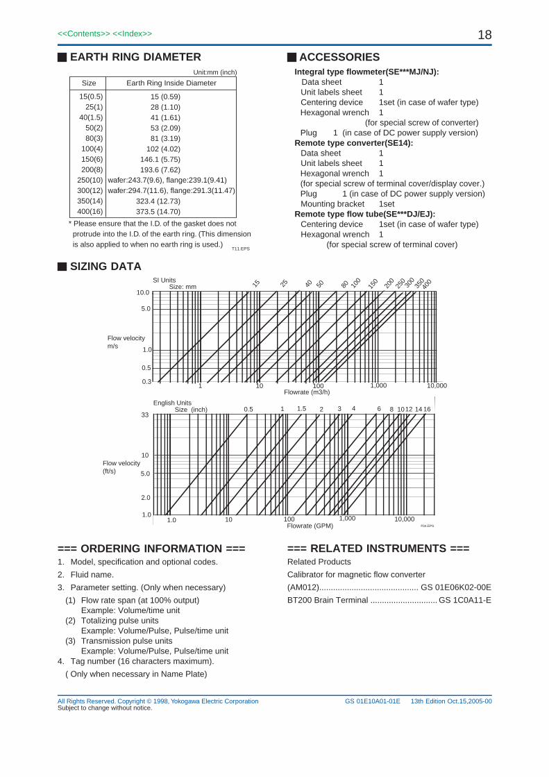
EARTH RING DIAMETER
Size
15(0.5)25(1)
40(1.5)50(2)80(3)
100(4)150(6)200(8)
250(10)300(12)350(14)400(16)
Earth Ring Inside Diameter
15 (0.59)28 (1.10)41 (1.61)53 (2.09)81 (3.19)
102 (4.02)146.1 (5.75)193.6 (7.62)
323.4 (12.73)373.5 (14.70)
Unit:mm (inch)
* Please ensure that the I.D. of the gasket does not protrude into the I.D. of the earth ring. (This dimension is also applied to when no earth ring is used.)
T11.EPS
wafer:243.7(9.6), flange:239.1(9.41)wafer:294.7(11.6), flange:291.3(11.47)
=== RELATED INSTRUMENTS ===Related Products
Calibrator for magnetic flow converter
(AM012)........................................... GS 01E06K02-00E
BT200 Brain Terminal ............................. GS 1C0A11-E
=== ORDERING INFORMATION ===1. Model, specification and optional codes.
2. Fluid name.
3. Parameter setting. (Only when necessary)
(1) Flow rate span (at 100% output)Example: Volume/time unit
(2) Totalizing pulse unitsExample: Volume/Pulse, Pulse/time unit
(3) Transmission pulse unitsExample: Volume/Pulse, Pulse/time unit
4. Tag number (16 characters maximum).
( Only when necessary in Name Plate)
SIZING DATA15 25 40 50 80 10
0
150
200
250
300
350
Size: mm
1 10,0001,00010010
400
0.5
1.0
5.0
10.0
Flow velocitym/s
0.3
Flow velocity(ft/s)
33
5.0
1.0
10
2.0
0.5 1 21.5 3 4 6 12108 14 16Size (inch)English Units
SI Units
1.0 10,0001,00010010Flowrate (GPM) F04.EPS
Flowrate (m3/h)
ACCESSORIESIntegral type flowmeter(SE***MJ/NJ): Data sheet 1
Unit labels sheet 1Centering device 1set (in case of wafer type)Hexagonal wrench 1 (for special screw of converter)Plug 1 (in case of DC power supply version)
Remote type converter(SE14):Data sheet 1Unit labels sheet 1Hexagonal wrench 1(for special screw of terminal cover/display cover.)Plug 1 (in case of DC power supply version)Mounting bracket 1set
Remote type flow tube(SE***DJ/EJ):Centering device 1set (in case of wafer type)Hexagonal wrench 1
(for special screw of terminal cover)
Subject to change without notice.13th Edition Oct.15,2005-00