general instructions for use h-hm closed circuit axial...
TRANSCRIPT
1398THY005EN00 - 01-02-18
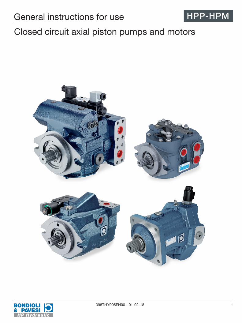
General instructions for use
Closed circuit axial piston pumps and motors
HPP-HPM

2 398THY005EN00 - 01-02-18
IntroductionThis manual contains instructions for the installation and operation of closed circuit axial piston pumps. The following instructions apply to standard products.
Due to the constant technological research that aims to improve the technical characteristics of our products, Bondioli & Pavesi reserves the right to modify its products and internal calibration and testing procedures without prior notice and/or official changes being made. For this reason, this material shall not constitute a base for legal proceedings.
Bondioli & Pavesi shall not be held liable for faults, incidents or modifications caused by a failure to comply with the instructions in this manual and a failure to comply with the safety standards in force, even if not included in this manual.Bondioli & Pavesi shall not be held liable for any errors in this manual; if in doubt, please contact our central office for more information.Failure to observe these instructions will result in the manufacturer's warranty being automatically voided.
This catalogue may not be reproduced, even partially, without specific authorisation in writing from Bondioli & Pavesi. This catalogue replaces all previous versions.
HPP-HPM
3398THY005EN00 - 01-02-18
Contents
Installation General instructions 4
Transport and storage 4
Installation position 6
Pipes and fittings 6
Filters 7
Temperature 7
Cleaning 7
Type of oil 8
Couplings 8
Start-up Precautions to be taken before start-up 9
Filling 9
System start-up 9
Flushing of system 9
Troubleshooting Introduction 11
Tables 11-12
Maintenance and checks Routine maintenance 13
Special maintenance 14
Required equipment 15
Checking efficiencies 15
Checking pump efficiency 15
Checking motor efficiency 16
Checking distributor plate 16
Checking cylinder block 17
Checking pistons and shoes 17
Checking shoe retainer plate 17
Checking air chamber 17
Checking swash plate 17
Checking distributor bushing 17
Checking shaft and bearing 17
Checking servo-control 17-18
Checking feed pump 18
Labelling 18
Protection of oil ports 18
Protection of components 18
Painting 19
HPP-HPM

4 398THY005EN00 - 01-02-18
InstallationTo ensure that Bondioli & Pavesi components operate correctly, the following recommendations must be observed during design and installation.
Depending on the weight and duration of transport (dimensions and weights can be found in the product specifications sheet or technical drawing), the following transport options are available:
Bondioli & Pavesi pumps weighing up to 15 kg can be manually transported for a short period of time if necessary.
Manual transport may be harmful to health.Use personal protective equipment (e.g., safety glasses, gloves, suitable work clothing, safety footwear).Avoid the manual handling of pumps with sensitive accessories (e.g., sensors or valves).
Axial piston units can be transported by connecting them to a lifting device, i.e. eye bolts or lifting straps.An axial piston unit can be transported suspended from an eye bolt screwed into the drive shaft if moved from outside; axial forces are applied with this transport option.Use eye bolts of the correct thread and size (the thread size is indicated in the technical drawing).Make sure that the eye bolt can lift the total weight of the axial piston unit plus 20%.
Suspended loads. When being transported with a lifting device, the axial piston unit may slip out of the lifting strap and cause injury.Use the widest possible lifting strap.Make sure that the lifting strap is securely attached to the axial piston unit.Only manually guide the axial piston unit for fine positioning or to prevent rocking.Do not stand or place your hands under suspended loads.Place the lifting strap around the piston unit without passing over the fastening elements (e,g., valves) or other accessories.
General instructions
Transport and storage
Manual transport
Warning!
Transport with lifting device
Transport with lifting strap
Warning!
HPP-HPM

5398THY005EN00 - 01-02-18
Installation
The storage areas must be free of corrosive materials and gases.To avoid damaging the seals, do not use ozone-releasing equipment (e.g., mercury vapour lamps, high voltage equipment, electric motors, sources of electrical sparks or discharges) in the storage areas.The storage areas must be completely dry.The ideal storage temperature must be between +5 °C and +20 °C (minimum storage temperature -50 °C, except for units that have electronic components; maximum storage temperature +60 °C).Avoid exposing the piston units to high light irradiation (e.g. bright windows or direct fluorescent lighting).Do not stack the axial piston units and protect them from knocks.Do not store the axial piston units on the drive shaft or accessories (e.g. sensors or valves).Check the axial piston units once a month to ensure they are stored correctly.The axial piston units are supplied by the manufacturer with anti-corrosion packaging.An axial piston unit can be stored for a maximum of 12 months with standard protection or a maximum of 24 months with corrosion protection.
The warranty will no longer be valid if the storage requirements and conditions are not complied with or the maximum period of storage has expired.
- Check the entire axial piston unit for damage and corroded areas before installation.- Perform a test run to check that the axial piston unit operates correctly.- If stored for over 24 months, the shaft seal must be replaced.
When the maximum storage period expires or if you have questions regarding repair work or spare parts, contact the Bondioli & Pavesi customer service.The instructions below refer to axial piston units that use mineral oil-based hydraulic fluid. Other hydraulic fluids require specific methods of storage.
Storage
Procedure when maximum storage period
has expired
HPP-HPM
6 398THY005EN00 - 01-02-18
- Empty and clean the axial piston unit.- For storage periods of up to 12 months, coat the inside of the axial piston unit with mineral oil and fill with approximately 100 ml of mineral oil.- For storage periods of up to 24 months, fill the axial piston unit with a VCI 329 corrosion inhibitor (20 ml). The unit is filled via the reservoir port.- Seal all the oil ports.- Moisten the painted surfaces of the axial piston unit with mineral oil or an easily removable corrosion protection agent, e.g., acid-free grease.- Wrap all the oil ports on the axial piston unit in protective anti-corrosion film and store the unit where it is protected from knocks.
When assembling the component and the drain pipes, make sure they are in a position in which the internal parts remain lubricated by the oil during long periods of machine shutdown.The oil level of the reservoir should be higher than that of the pump to prevent cavitation and facilitate boost pump suction.If this is not possible, the difference between the reservoir oil level and the pump must not in any case exceed 0.5 m.When placing the component on the machine, make sure that parts of it do not obstruct the movement of adjusting screws and parts on the pump when in operation.
The pipes that connect the pump to the hydraulic circuit must be able to withstand the required operating pressure. Sharp bends in the pipes should be avoided.Eye unions should not be used.The pipe cross section must also be sufficiently large to keep the fluid velocity within acceptable limits:
DELIVERY PIPES: 5 m/sec MAXRETURN, DRAIN PIPES: 3 m/sec MAXSUCTION PIPES: 1.5 m/sec MAX
The following simplified formula can be used to calculate the fluid velocity:
"v = " "Q x 21.2" /"d" ^"2" where: v = fluid velocity (m/sec) Q = fluid flow rate (l/min) d = inner diameter of pipe (mm)
Pump suction must use a pipe that can withstand vacuums and sharp bends, blockages and excessive lengths (over two metres) should be avoided. Check that at maximum pump speed the vacuum during suction does not exceed 0.5 bar with cold oil and 0.2 bar with oil at working temperature (50-70 °C).
The drain line must be installed in a position that guarantees that the pump is filled even if the system is shut down for a long period of time.The drain line must be left as free as possible to discharge into the reservoir.Do not connect the drain line of other parts of the hydraulic system to the drain line of the Bondioli & Pavesi components.
Bondioli & Pavesi recommends this procedure:
Installation position
Pipes and fittings
Suction
Checking
Drain line
InstallationHPP-HPM

7398THY005EN00 - 01-02-18
Check that the total head loss on the drain line does not create pressure exceeding 1.5 bar in the pump case.
Drain pipes normally have variable flow velocities. Check that any pressure peaks during operating do not exceed 1.5 bar.
A filter with a filtering level of 10 microns (ISO 16 - 13), with a flow rate that is suitable for the oil flow, must always be installed on the pump suction line.If the Bondioli & Pavesi pump is supplied with a pressure filter, a filter cartridge with an absolute rating of at least 90 must be installed on the suction side to protect the feed pump.In any case, the suction filter must not have a by-pass valve.The selected filters must have a vacuum gauge and clogging indicator.The size of the filter depends on the pump speed, the type of fluid used, the pump start-up and operating temperatures, the pollution causes by accidental or systematic entry of contaminants into the system and the frequency with which the filter cartridge is serviced and replaced.During the maintenance cycles, do not contaminate the suction circuit when replacing the filter cartridge.
- after the first 50 hours of operation - when the indicator shows that the filter is clogged- every 500 hours of operation
For information on how to assemble the filter unit and replace the filter cartridge, see Chapter 4. Maintenance and checks paragraph 4.2 Routine maintenance.
The temperature of the fluid in the reservoir must not exceed 80°C for any reason whatsoever; higher values may damage the components and lead to a rapid deterioration in performance.To keep the temperature low:
- do not install the components near heat emitters (heat engines, mufflers, radiators, etc.).- use oil reservoirs with a capacity of over 50 litres at least.- use adequately sized pipes- adequately size the system heat exchanger.Keep the radiating surfaces clean.
Suitable detectors should be installed that warn the operator when high temperatures are reached or stop machine operating to prevent overheating.
Correct cleaning of all the system parts is essential and should be done before start-up.The main connection operations should be performed in a clean, dust-free environment and debris of all types must be removed immediately before it enters the circuit.Bondioli & Pavesi pumps are delivered with the ports closed by protective plugs which should only be removed when the pump is connected.When the component has been installed, it is good practice to add a small amount of hydraulic oil to protect the internal parts until the hydraulic system is filled.Pickle the pipes and wash them with suitable solvents.Dry thoroughly with compressed air to remove all traces of solvent.
Checking
Warning!
Filters
Filters should normally be replaced:
Temperature
Cleaning
Installation HPP-HPM

8 398THY005EN00 - 01-02-18
Use pre-filtered mineral oil-based hydraulic fluid containing antiwear and antifoam additives. Check that the fluid viscosity required for correct operating corresponds: minimum 10 mm2/s (for short periods), maximum 1000 mm2/s (for short periods at start-up), recommended viscosity 15-90 mm2/s.
The required contamination class is ISO 4406 20/18/15 (NAS 1638-9).
Bear in mind that no axial or radial load should be directly applied to the Bondioli & Pavesi pump or hydraulic motor shaft.In any case, provide adequate coupling joints that do not transmit loads to the shaft.
Type of oil
Couplings
InstallationHPP-HPM

9398THY005EN00 - 01-02-18
Thoroughly clean all the parts of the system that will come into contact with the circuit hydraulic fluid (reservoir, pipes, heat exchangers, filters,etc.)Make sure that nothing prevents normal suction of the pump (taps closed on the suction line, loose connections which could cause water to enter the pipes, etc.).Pressure gauges must also be installed to check the operating pressure on all the intakes normally present on the pump (see par. 4.4).
When filling use hydraulic fluid filtered at 10 micron to prevent foreign bodies entering the system. Even new hydraulic fluids may contain impurities.Fill the reservoir and the other large capacity components with fluid (filters, heat exchanger).Fill the pump and hydraulic motor with oil using one of the drain holes and make sure that the case is at least 50% full.
When the system starts up, all the air in the hydraulic circuit must be eliminated before the circuit is subjected to high stresses.To do this, the machine transmission components must be able to rotate freely without load.If you cannot disable the mechanical transmission on the moving parts, you can, for example, lift the machine off the ground so that the transmission rotates freely.
Do not rotate the pump and the hydraulic motor unless the pump has been filled, as stated in the previous paragraph. The components may be seriously damaged.
Make sure that the pump is regulated at zero displacement.Run the pump at minimum speed (for example, by running the diesel engine in stops and starts, using only the starter motor) until the feed pump starts to operate normally.Correct operating of the feed pump can be seen on the pressure gauge on the pump feed circuit which indicates a minimum pressure of a few bars.The diesel engine can now be started at minimum speed.Operate the pump in both directions and make sure that the direction of rotation of the controlled parts is correct.Run the transmission until you are certain that all the air has been expelled and there are air/oil emulsions. A few minutes are normally sufficient.Increase the rotational speed and check that the pressure in the booster circuit reaches a value of 18-20 bar and that the vacuum of the pressure gauge on the suction line does not exceed 0.5 bar with cold oil and 0.2 bar with hot oil.Gradually increase the load and check the maximum operating pressure on the high-pressure pressure gauges.During the various start-up stages, check the hydraulic fluid level in the reservoir and top up if necessary.
"Flushing of the system" means eliminating, as far as possible, all the contaminating particles in the hydraulic fluid and system components from the hydraulic circuit.Do this when the machine is new, when the system has been heavily overhauled, important parts have been replaced or faults have occurred when may introduce metal particles into the circuit.Flush before putting the components under stress.Use additional 3-10 micron filters which should be temporarily placed on the pipes which run back to the reservoir and the suction ones, sized according to the required flow rates and pressures.
Precautions to be taken before start-up
Filling
System start-up
Warning!
Flushing of system
Start-up HPP-HPM
10 398THY005EN00 - 01-02-18
Two examples of inline filter installation are:- connecting the filter instead of the motor.- connecting the filter on the branch that runs back to the pump before it returns to the pump, excluding the motor by using a temporary connection (preferred solution).
Operate the transmission so that the manoeuvres cause the particulate pollutants to come off the pipes and the parts of the hydraulic system.Flushing must last long enough for all the hydraulic fluid to pass through the filters at least 15-20 times.Flushing should be considered satisfactory when the level of oil contamination, according to the ISO 4406 Standard, is 20/18/15 or lower.
If there are several parallel-connected motors in the circuit, flushing must be performed on each "branch" of the circuit, i.e. the pipes that connect each motor to the point where the flow is divided. To do this, we recommend series connecting a high pressure ball shut-off valve to the bypass pipe of each motor. The corresponding circuit branch with the valve open will be flushed whereas the others will be closed. By repeating the same procedure for each branch, the circuit will be completely flushed.After flushing, the filter and any pipes and auxiliary valves used must be removed, the hydraulic fluid replaced and the system returned to a normal operating configuration.The machine can now be tested under load and adjustments can be made if necessary.
Installation of filter
N.B.
Start-upHPP-HPM

11398THY005EN00 - 01-02-18
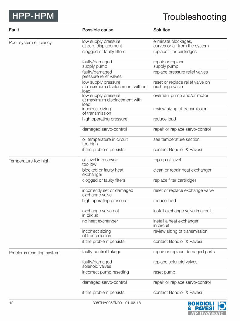
The components listed in this troubleshooting procedure can be inspected, adjusted, repaired or replaced according to the procedures outlined in this manual.The information found in this section serves as a guide for identifying the causes of faults or malfunctioning in the hydraulic components.It is therefore a useful tool for eliminating problems that are easy to solve.
Experience has shown that we can divide the types of problem into a number of general cases.These cases are listed in the tables below which show step by step the checks that must be carried out and the required adjustment or replacement of parts.
Introduction
Troubleshooting
Fault Possible cause Solution
Transmission does not work in both directions
oil level in reservoir too low top up oil level
incorrect direction of rotation of pump
invert rotation
clogged or faulty filters replace filter cartridges
no supply pressure contact Bondioli & Pavesi
Transmission does not work in one direction
faulty control linkage repair or replace damaged parts
faulty/damaged solenoid valves replace solenoid valves
faulty/damaged pressure relief valves
replace pressure relief valves
incorrectly positioned pressure relief valves
change position
incorrectly set or damaged exchange valve
reset or replace exchange valve
damaged servo-control repair or replace servo-control
if the problem persists contact Bondioli & Pavesi
HPP-HPM
12 398THY005EN00 - 01-02-18
Fault Possible cause Solution
Poor system efficiency low supply pressure at zero displacement
eliminate blockages, curves or air from the system
clogged or faulty filters replace filter cartridges
faulty/damaged supply pump
repair or replace supply pump
faulty/damaged pressure relief valves
replace pressure relief valves
low supply pressure at maximum displacement without load
reset or replace relief valve on exchange valve
low supply pressure at maximum displacement with load
overhaul pump and/or motor
incorrect sizing of transmission
review sizing of transmission
high operating pressure reduce load
damaged servo-control repair or replace servo-control
oil temperature in circuit too high
see temperature section
if the problem persists contact Bondioli & Pavesi
Temperature too high oil level in reservoir too low
top up oil level
blocked or faulty heat exchanger
clean or repair heat exchanger
clogged or faulty filters replace filter cartridges
incorrectly set or damaged exchange valve
reset or replace exchange valve
high operating pressure reduce load
exchange valve not in circuit
install exchange valve in circuit
no heat exchanger install a heat exchanger in circuit
incorrect sizing of transmission
review sizing of transmission
if the problem persists contact Bondioli & Pavesi
Problems resetting system faulty control linkage repair or replace damaged parts
faulty/damaged solenoid valves
replace solenoid valves
incorrect pump resetting reset pump
damaged servo-control repair or replace servo-control
if the problem persists contact Bondioli & Pavesi
TroubleshootingHPP-HPM

13398THY005EN00 - 01-02-18
Routine maintenance work on a hydraulic system is usually carried out at regular intervals and involves:- checking the fluid level and topping up if necessary.- cleaning and maintenance of the radiating surfaces.- replacing the filters.- replacing the oil.
- setting and regulating the pump during the first machine start-up.- removing and reassembling the pump and motor, or parts of them.- checking parts of the pump.
- perform all the operations in a clean, dust-free environment so that foreign particles are not introduced into the components.- plug all the pressure ports with plastic caps as soon as the hydraulic pipes have been disconnected.- replace the seals each time the components are opened.
We recommend procuring seal kits before working on the components.
The recommended maintenance intervals are:
Before every machine start-up:- check the oil level in the reservoir- clean the heat exchanger.- check that the reservoir breather is clean.
After the first 50 hours of operation:- replace the oil filter
Every 500 hours or at least once a year:- replace the oil filter
Every 1000 hours or at least once every two years:- change the oil in the hydraulic system (do this when the oil is hot).- replace the reservoir breather filter
After repair work and/or overhauling of the system components:- replace the oil filter- change the oil in the hydraulic system (do this when the oil is hot).
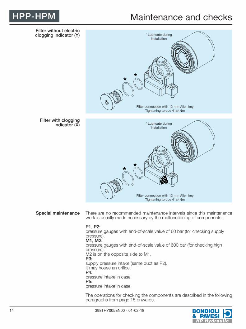
When installing the filter unit, lubricate the cartridge seal before tightening the connection. A 12 mm hex key is used to tighten the filter cartridge connection and the tightening torque is 41±4Nm. In the version with an electrical clogging indicator, the indicator will signal, by way of an acoustic and/or visual device connected to it (not supplied by Bondioli & Pavesi), if the filter cartridge is full.
Warning!
Special maintenance involves:
We recommend:
Routine maintenance
Maintenance and checks HPP-HPM
14 398THY005EN00 - 01-02-18
There are no recommended maintenance intervals since this maintenance work is usually made necessary by the malfunctioning of components.
P1, P2: pressure gauges with end-of-scale value of 60 bar (for checking supply pressure).M1, M2: pressure gauges with end-of-scale value of 600 bar (for checking high pressure). M2 is on the opposite side to M1.P3: supply pressure intake (same duct as P2).It may house an orifice.P4: pressure intake in case.P5:pressure intake in case.
The operations for checking the components are described in the following paragraphs from page 15 onwards.
Special maintenance
* *
* *
Maintenance and checksFilter without electric clogging indicator (Y)
Filter with clogging indicator (X) * Lubricate during
installation
* Lubricate during installation
Filter connection with 12 mm Allen keyTightening torque 41±4Nm
Filter connection with 12 mm Allen keyTightening torque 41±4Nm
HPP-HPM

15398THY005EN00 - 01-02-18
List of pressure gauges and their connections.Positions and connections vary according to the pump model.
If the hydrostatic transmission shows poor efficiency, you may have to check the efficiency of the hydraulic components to establish whether it is the pump or the hydraulic motor that needs to be repaired or overhauled.In this way, you can concentrate on the component that requires maintenance without making pointless attempts that may jeopardise the functionality of the entire hydraulic system.
To check pump efficiency, install a pressure gauge on the supply pressure intake (with end-of-scale value of 600 bar) and a pressure gauge on the high pressure intake (with end-of-scale value of 600 bar).
In any case, pay maximum attention to the moving parts and comply with all the safety regulations and standards in force.Perform this test as quickly as possible to avoid overheating the pump and the system.
- plug the high pressure feed ports with caps and seals that can withstand at least double the maximum pressure of the pump.- operate the pump at 1200 rpm with zero displacement; with the oil at approximately 50 degrees, check that the supply pressure is 18-20 bar.- slightly increase the pump displacement; check that the supply pressure does not drop suddenly and the operating pressure is the same as the set pressure of the pressure relief valves.- if the supply pressure drops suddenly and the pump cannot open the high pressure relief valves, component wear and play have probably reached a level that makes overhauling or replacing the component necessary.
Required equipment
Checking efficiencies
Checking pump efficiency
Warning!
M1
M2
P2
P1
P3 P4
Maintenance and checks HPP-HPM

16 398THY005EN00 - 01-02-18
In this case, the check is performed on the quantity of oil that comes out of the motor drain port.A visual check can be performed without using a measurer since a damaged motor immediately produces a considerable amount of drain flow compared with the small stream of oil normally produced by a motor that is in good condition.Make sure you perform the check correctly and see the actual motor drain fluid and not "cleaning" oil from the pump or oil discharged by an exchange valve.
In any case, pay maximum attention to the moving parts and comply with all the safety regulations and standards in force.Perform this test as quickly as possible to avoid overheating the pump and the system.
- disconnect the drain pipes that connect the hydraulic motor case to the system.
System without washing of motor and without exchange valve:- connect a short length of pipe on the motor drain port and discharge it into an external container so that you can visually check the amount of drain flow.
System with exchange valve on motor:- fully tighten the adjusting screw on the exchange valve so that it is completely excluded.- connect a short length of pipe on the motor drain port and discharge it into an external container so that you can visually check the amount of drain flow.
System with washing of motor:- connect the wash pipe leading from the pump to the previous drain pipe on the motor using suitable connections.- plug one of the two drain holes left open on the body of the motor.- connect a short length of pipe on the other motor drain port and discharge it into an external container so that you can visually check the amount of drain flow.- operate the pump at 1200 rpm with zero displacement; with the oil at approximately 50 degrees, check that the supply pressure is 18-20 bar. In these conditions, motor drain should be practically zero.- increase the pump displacement to maximum; check that the drain port of the hydraulic motor has very low values when unloaded (in these conditions normally only a thin stream of oil comes out of the drain port).- Gradually increase the braking load on the hydraulic motor and check that the drain flow increases in a limited way (at maximum load, a motor does not drain more than 2 litres a minute in good conditions).- a motor that drains a full pipe flow when under stress needs a complete overhaul.
The same procedure can normally be used to check hydraulic motors made by other manufacturers, driven by Bondioli & Pavesi pumps.
The bimetal plate consists of a steel base with a bronze lining; it is vulnerable to wear due to impurities in the oil, the use of unsuitable fluids and very high temperatures.The scoring on the bronze surface in the area between the two distribution slots is usually caused by abrasive solid impurities in the hydraulic fluid.Components with work surfaces with very prominent scoring which can be felt with a fingernail do not guarantee the necessary seal.
Checking motor efficiency
Warning!
Case 1
Case 2
Case 3
Checking distributor plate
Maintenance and checksHPP-HPM
17398THY005EN00 - 01-02-18
The surfaces must therefore be lapped (a maximum of 2 times) or the part replaced if the wear is too severe.
The same considerations made in the previous paragraph apply to the surface of the cylinder block that rotates in contact with the bimetal plate.The piston sliding bushings and piston play must also be checked.If there is a considerable amount of play and heavy scoring, the cylinder block complete with pistons must be replaced.
Every piston ends in a ball joint that houses the sliding shoe on the swash plate.Solid, abrasive impurities cause scoring on the shoe and piston; if this is very severe we recommend replacing the parts. If it is very light, try to repair the surface by polishing with lens tissue or lapping.A faulty hydrostatic bearing will cause the shoe and the piston to seize; a very high rotational speed, on the other hand, will cause rounding at the edges on these parts.In both cases, and if there is too much free play between the pistons and the shoes, they will have to be replaced.
A change in the original colour of the shoe retainer plate indicates that the unit has operated at extremely high temperatures which may deform the disc and increase the wear on the entire rotating unit and the swash plate.The disc must be replaced when annular scoring, caused by impurities or wear, which can be felt with a fingernail appears in the area where it comes into contact with the shoes and the area that rests on the air chamber.
It must be replaced if the scoring, which is usually caused by impurities in the oil, can be felt with a fingernail and if there is considerable wear, a visible sign of faulty lubrication. It must be replaced if there are signs of wear, such as scoring which can be felt with a fingernail, seizure caused by impurities in the oil, overheating or a faulty hydrostatic bearing on the pistons.Also check that the sliding area on the roller bearings or plain bearings is not damaged; if scoring can be seen, the component must be replaced.
Check the bushing in the distributor where the pump shaft rotates for signs of wear in the anti-friction material, seizure or excessive play with the shaft. If necessary, replace the part.
Check the part of the shaft that rotates inside the distributor bushing for signs of wear or seizure.check that the part of the round or grooved shaft that drives the pump does not show signs of abnormal wear.check the bearing rollers and races: there must not be any play or signs or wear or seizure. If there is, replace the shaft and the bearing.
Check that the piston does not have scoring which can be felt with a fingernail and check that the sealed areas of the servo-control body in the pump are not damaged.Check that play between the piston and its seat is kept to a minimum while still allowing the piston to move freely without blocking.
Checking cylinder block
Checking pistons and shoes
Checking shoe retainer plate
Checking air chamber
Checking swash plate
Checking distributor bushing
Checking shaft and bearing
Checking servo-control
Maintenance and checks HPP-HPM

18 398THY005EN00 - 01-02-18
Check that the parts in the pump body that form the servo-control are not broken or shows signs of abnormal wear (pilot valve, pilot valve body, rocker arm).
Check that the solenoid valves are working correctly and, if present, that the orifices underneath them are perfectly clean.
Check the seal on the two O-rings in the servo-control body in the pump.
Check there is no scoring on:- all the surfaces of the two rotors- the surface of the pump distributor- the inside of the feed pump body.
This type of wear is caused by impurities in the suction oil which has not been correctly filtered.This also applies to tandem-configuration pumps.
Always replace the feed pump complete with the two rotors and external body to ensure that design tolerances are maintained.
An identification plate is attached to all the Bondioli & Pavesi components that leave the factory, both new and overhauled, which lists in full the product type and code, the job number and a progressive number.If a request for spare parts is made, it is very important that all the information on this identification plate is provided.If a product is overhauled, the plate is replaced with updated information; every modification to the pump that involves the issue of a new code must be indelibly marked on the plate.
All Bondioli & Pavesi components are shipped with the oil ports protected with plugs.Metal plugs are used for unused ports and plastic ones for all the others.The plugs should be left in position until the components are installed in the system to prevent the entry of humidity and pollutants that may damage them.If a component has to be dismantled for repair and/or overhauling, we recommend closing the oil ports with plugs to protect them from pollution and dirt.
Bondioli & Pavesi components are usually shipped in plastic bags to protect them from humidity and oxidation.This packaging protects the component for a normal shipping and storage period which does not exceed 20 days.For longer periods of storage, we recommend unpacking the component and applying protective oil to the exterior to prevent oxidation.Store the component in an enclosed area with low humidity.
For manual and feedback servo-controls:
Checking feed pump
Labelling
Protection of oil ports
Protection of components
Maintenance and checks
For servo-controls with solenoid valves:
For servo-controls without spring on piston:
Warning!
HPP-HPM

19398THY005EN00 - 01-02-18
If Bondioli & Pavesi components require painting, it is very important to protect the mating surfaces, i.e.:
- flanges- fittings- connection ports- identification plate
The following components, if present, should also be protected:
- solenoid valves- operating levers- filter cartridges- electronic connections- ECUs- pressure, speed, angle sensors
If electrostatically painted, the electrical/electronic components on the Bondioli & Pavesi pumps and motors, for example pressure, speed and angle sensors, must be protected in the following way:- Each sensor must be connected to the product case with a dedicated cable. Earthing should be carried out using the thread on top of the shaft or the servo-control and flat washers inserted to protect the wire terminal.
Painting
Warning!:
Maintenance and checks
* Protect from paint
* Protect from paint
HPP-HPM

20 398THY005EN00 - 01-02-18