general information atomic+ undercut
TRANSCRIPT
TECH
NICA
L GU
IDE
– M
ECHA
NICA
L AN
CHor
s ©
2021
DEW
ALT
– r
EV. D
SECTION CONTENTS
ANCHORS & FASTENERS General InformatIon
1
Mec
han
ical
an
cho
rs
General Information.........................1Material Specifications ...................2Anchor Specifications .....................2Installation Instructions ..................3Installation Specifications ..............4Performance Data ............................5Ordering Information .....................10
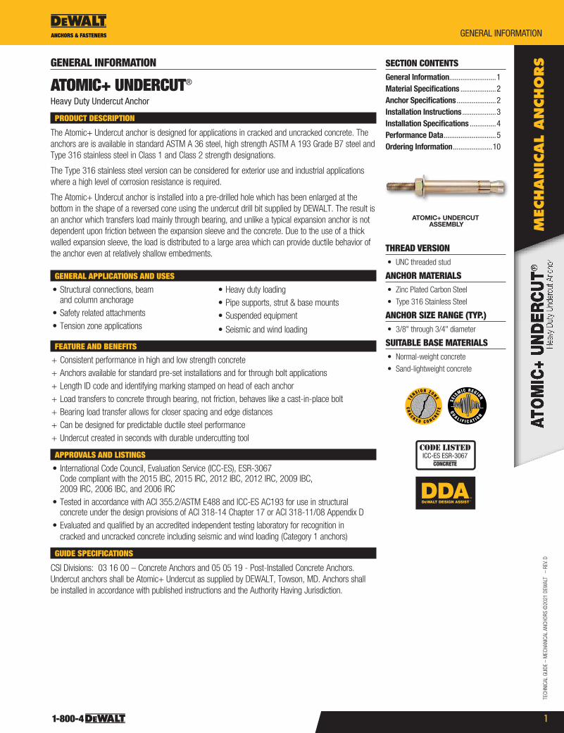
ATOMIC+ UNDERCUT ASSEMBLY
THREAD VERSION• UNC threaded stud
ANCHOR MATERIALS• Zinc Plated Carbon steel
• Type 316 stainless steel
ANCHOR SIZE RANGE (TYP.)• 3/8" through 3/4" diameter
SUITABLE BASE MATERIALS• Normal-weight concrete
• sand-lightweight concrete
CR
AC K E D C O N C R
ET
E
T E
N S I O N Z O NE
QU
A L I F I C A T I O N
SEIS
M IC REG ION
CODE LISTEDICC-eS eSr-3067
CONCRETE
GENERAL INFORMATION
ATOMIC+ UNDERCUT®
Heavy Duty Undercut anchor
PRODUCT DESCRIPTION
The Atomic+ Undercut anchor is designed for applications in cracked and uncracked concrete. The anchors are is available in standard AsTM A 36 steel, high strength AsTM A 193 Grade B7 steel and Type 316 stainless steel in Class 1 and Class 2 strength designations.
The Type 316 stainless steel version can be considered for exterior use and industrial applications where a high level of corrosion resistance is required.
The Atomic+ Undercut anchor is installed into a pre-drilled hole which has been enlarged at the bottom in the shape of a reversed cone using the undercut drill bit supplied by DEWALT. The result is an anchor which transfers load mainly through bearing, and unlike a typical expansion anchor is not dependent upon friction between the expansion sleeve and the concrete. Due to the use of a thick walled expansion sleeve, the load is distributed to a large area which can provide ductile behavior of the anchor even at relatively shallow embedments.
GENERAL APPLICATIONS AND USES
• structural connections, beam and column anchorage
• safety related attachments• Tension zone applications
• Heavy duty loading• Pipe supports, strut & base mounts• suspended equipment
• seismic and wind loading
FEATURE AND BENEFITS
+ Consistent performance in high and low strength concrete + Anchors available for standard pre-set installations and for through bolt applications + Length ID code and identifying marking stamped on head of each anchor + Load transfers to concrete through bearing, not friction, behaves like a cast-in-place bolt + Bearing load transfer allows for closer spacing and edge distances + Can be designed for predictable ductile steel performance + Undercut created in seconds with durable undercutting tool
APPROVALS AND LISTINGS
• International Code Council, Evaluation service (ICC-Es), Esr-3067 Code compliant with the 2015 IBC, 2015 IrC, 2012 IBC, 2012 IrC, 2009 IBC, 2009 IrC, 2006 IBC, and 2006 IrC
• Tested in accordance with ACI 355.2/AsTM E488 and ICC-Es AC193 for use in structural concrete under the design provisions of ACI 318-14 Chapter 17 or ACI 318-11/08 Appendix D
• Evaluated and qualified by an accredited independent testing laboratory for recognition in cracked and uncracked concrete including seismic and wind loading (Category 1 anchors)
GUIDE SPECIFICATIONS
CsI Divisions: 03 16 00 – Concrete Anchors and 05 05 19 - Post-Installed Concrete Anchors. Undercut anchors shall be Atomic+ Undercut as supplied by DEWALT, Towson, MD. Anchors shall be installed in accordance with published instructions and the Authority Having Jurisdiction.

TECHNICAL GUIDE – MECHANICAL ANCHors ©
2021 DEWALT – rEV. D
ANCHORS & FASTENERSmaterIal SpeCIfICatIonS
Mec
han
ical a
ncho
rs
2
MATERIAL SPECIFICATIONS
Anchor ComponentAnchor Designation
Carbon Steel High Strength Carbon Steel Stainless Steel (Type 316) High Strength Stainless Steel (Type 316)
Threaded rod AsTM A 36 AsTM A 193, Grade B7 AsTM A193, Grade B8M, Class 1 AsTM A193, Grade B8M, Class 2Expansion Coupling (Cone) AsTM A 108 12L14 AsTM A 274 sExpansion/spacer sleeve AsTM A 513 Type 5 AsTM A 274 s
Hex Nut AsTM A 563, Grade C AsTM A 194, Grade 8M
Washer AsTM F 844; Meets dimensional requirements of ANsI B18.22.1, Type A plain
Type 316 ss; Meets dimensional requirements of ANsI B18.22.1, Type A plain
Plating Zinc plating in accordance with AsTM B 633, sC1 (Fe/Zn 5) or equivalent; Minimum plating requirement for Mild service Condition Not applicable
ANCHOR SPECIFICATIONSDimensional Characteristics Table for Atomic+ Undercut
Anchor Designation Anchor Type
Anchor RodASTM
Designation
Rod Diameter,
db (inch)
Anchor Length,
lb (inches)
Sleeve Length, ls
(inches)
Sleeve Diameter,
ds (inch)
Expansion Coupling Diameter dc (inch)
Max. Fixture Thickness, t (inches)
03100sD standard A 36 3/8 5-1/2 2-3/4 5/8 5/8 1-3/403102sD Through bolt (TB) A 36 3/8 5-1/2 4-1/2 5/8 5/8 1-3/403600sD standard A 193, Grade B8M, Class 1 3/8 5-1/2 2-3/4 5/8 5/8 1-3/403602sD Through bolt (TB) A 193, Grade B8M, Class 1 3/8 5-1/2 4-1/2 5/8 5/8 1-3/403603sD standard A193, Grade B8M, Class 2 3/8 6-3/4 4 5/8 5/8 1-3/403605sD Through Bolt (TB) A193, Grade B8M, Class 2 3/8 6-3/4 5-3/4 5/8 5/8 1-3/403104sD standard A 193, Grade B7 3/8 6-3/4 4 5/8 5/8 1-3/403106sD Through bolt (TB) A 193, Grade B7 3/8 6-3/4 5-3/4 5/8 5/8 1-3/403108sD standard A 36 1/2 7 4 3/4 3/4 1-3/403110sD Through bolt (TB) A 36 1/2 7 5-3/4 3/4 3/4 1-3/403608sD standard A 193, Grade B8M, Class 1 1/2 7 4 3/4 3/4 1-3/403610sD Through bolt (TB) A 193, Grade B8M, Class 1 1/2 7 5-3/4 3/4 3/4 1-3/403609sD standard A193, Grade B8M, Class 2 1/2 8 5 3/4 3/4 1-3/403613sD Through Bolt (TB) A193, Grade B8M, Class 2 1/2 8 6-3/4 3/4 3/4 1-3/403112sD standard A 193, Grade B7 1/2 8 5 3/4 3/4 1-3/403114sD Through bolt (TB) A 193, Grade B7 1/2 8 6-3/4 3/4 3/4 1-3/403116sD standard A 193, Grade B7 1/2 9-3/4 6-3/4 3/4 3/4 1-3/403118sD Through bolt (TB) A 193, Grade B7 1/2 9-3/4 8-1/2 3/4 3/4 1-3/403120sD standard A 36 5/8 7-3/4 4-1/2 1 1 1-3/403122sD Through bolt (TB) A 36 5/8 7-3/4 6-1/4 1 1 1-3/403620sD standard A 193, Grade B8M, Class 1 5/8 7-3/4 4-1/2 1 1 1-3/403622sD Through bolt (TB) A 193, Grade B8M, Class 1 5/8 7-3/4 6-1/4 1 1 1-3/403635sD standard A193, Grade B8M, Class 2 5/8 10-3/4 7-1/2 1 1 1-3/403639sD Through Bolt (TB) A193, Grade B8M, Class 2 5/8 10-3/4 9-1/4 1 1 1-3/403124sD standard A 193, Grade B7 5/8 10-3/4 7-1/2 1 1 1-3/403126sD Through bolt (TB) A 193, Grade B7 5/8 10-3/4 9-1/4 1 1 1-3/403128sD standard A 193, Grade B7 5/8 12-1/4 9 1 1 1-3/403130sD Through bolt (TB) A 193, Grade B7 5/8 12-1/4 10-3/4 1 1 1-3/403132sD standard A 36 3/4 8-5/8 5 1-1/8 1-1/8 1-3/403134sD Through bolt (TB) A 36 3/4 8-5/8 6-3/4 1-1/8 1-1/8 1-3/403632sD standard A 193, Grade B8M, Class 1 3/4 8-5/8 5 1-1/8 1-1/8 1-3/403634sD Through bolt (TB) A 193, Grade B8M, Class 1 3/4 8-5/8 6-3/4 1-1/8 1-1/8 1-3/403648sD standard A193, Grade B8M, Class 2 3/4 13-5/8 10 1-1/8 1-1/8 1-3/403649sD Through Bolt (TB) A193, Grade B8M, Class 2 3/4 13-5/8 11-3/4 1-1/8 1-1/8 1-3/403136sD standard A 193, Grade B7 3/4 13-5/8 10 1-1/8 1-1/8 1-3/403138sD Through bolt (TB) A 193, Grade B7 3/4 13-5/8 11-3/4 1-1/8 1-1/8 1-3/4
Atomic+ Undercut Anchor Detail Head Marking
lb
db
ls
dsdc
expansion couplingexpansion sleeve
washer
hex nutLegendLetter Code = Length Identification Mark‘+’ symbol = strength Design Compliant Anchor (see ordering information)
Length IdentificationMark A B C D E F G H I J K L M N O P Q R S T
From 1-1/2" 2" 2-1/2" 3" 3-1/2" 4" 4-1/2" 5" 5-1/2" 6" 6-1/2" 7" 7-1/2" 8" 8-1/2" 9" 9-1/2" 10" 11" 12"
Up to but not
including2" 2-1/2" 3" 3-1/2" 4" 4-1/2" 5" 5-1/2" 6" 6-1/2" 7" 7-1/2" 8" 8-1/2" 9" 9-1/2" 10" 11" 12" 13"
Length identification mark indicates overall length of anchor.

TECH
NICA
L GU
IDE
– M
ECHA
NICA
L AN
CHor
s ©
2021
DEW
ALT
– r
EV. D
ANCHORS & FASTENERS InStallatIon InStrUCtIonS
3
Mec
han
ical
an
cho
rsINSTALLATION INSTRUCTIONS
Installation Instructions for Atomic+ Undercut Anchors
1. Using the proper drill bit size, drill a hole into the base material to the required depth. The tolerances of the drill bit used should meet the requirements of ANsI standard B212.15.
2. remove dust and debris from the hole during drilling (e.g. dust extractor, hollow bit) or following drilling (e.g. suction, forced air) to extract loose particles created by drilling.
3. Insert the undercut bit and start the rotohammer. Undercutting is complete when the stopper sleeve is fully compressed (gap closed)
4. remove dust and debris from the hole following drilling (e.g. suction, forced air)
5. Insert anchor into hole. Place setting sleeve over anchor and drive the expansion sleeve over the expansion coupling.
6. Verify that the setting mark is visible on the theaded rod above the sleeve.
7. Apply proper torque; Do not exceed maximum torque.
Atomic+ Undercut Anchor Detail (before and after application of setting sleeve and attachment)
lb
dbitdbit
db
hnomho
lsdads
dc
t
lb
dbitdbit
hef
ho
dads
dc
lb
dbitdbit
db
hnomho, act
lsdads
dc
tpl tpl
lb
dbitdbit
hef
ho, act
dads
dc
Before After Before After
Standard Type (Pre-set Version) Through Bolt Type
Axial Stiffness Values, β, for Atomic+ Undercut Anchors in Normal-Weight Concrete1
Concrete State Notation UnitsNominal Anchor Size / Rod Diameter (inch)
3/8 1/2 5/8 3/4
Uncracked concrete
βmin 103 lbf/in 131
βm 103 lbf/in 930
βmax 103 lbf/in 1,444
Cracked concrete
βmin 103 lbf/in 91
βm 103 lbf/in 394
βmax 103 lbf/in 1,724
1. Valid for anchors with high strength threaded rod (A 193 Grade B7). For anchors with low strength threaded rod (A 36) values must be multiplied by 0.7.

TECHNICAL GUIDE – MECHANICAL ANCHors ©
2021 DEWALT – rEV. D
ANCHORS & FASTENERSInStallatIon SpeCIfICatIonS
Mec
han
ical a
ncho
rs
4
INSTALLATION SPECIFICATIONS
Installation Specifications for Atomic+ Undercut Anchors
Anchor Property/Setting Information Notation Units
Nominal Anchor Diameter
3/8 inch 1/2 inch 5/8 inch 3/4 inch
outside anchor diameter dain.
(mm)0.625 (15.9)
0.750 (19.1)
1.000 (25.4)
1.125 (28.6)
Minimum diameter of hole clearance in fixture2 dh
in. (mm)
7/16 (11.1)
9/16 (14.3)
11/16 (17.5)
13/16 (20.6)
Anchor rod designation, carbon steel AsTM - A36 A193
Gr. B7 A36 A193 Grade B7 A36 A193 Grade B7 A36 A193Gr. B7
Anchor rod designation, stainless steel AsTM -
A193Gr. B8MClass 1
A193Gr. B8MClass 2
A193Gr. B8MClass 1
A193Gr. B8MClass 2
-A193
Gr. B8MClass 1
A193Gr. B8MClass 2
-A193
Gr. B8MClass 1
A193Gr. B8MClass 2
Minimum nominal embedment depth hnom
in. (mm)
3-1/8 (79)
4-3/8 (111)
4-1/4 (108)
5-1/4 (133)
7 (178)
5 (127)
8 (203)
9-1/2 (241)
5-7/8 (149)
10-7/8 (276)
Effective embedment hefin.
(mm)2-3/4 (68)
4 (102)
4 (102)
5 (127)
6-3/4 (171)
4-1/2 (114)
7-1/2 (190)
9 (229)
5 (127)
10 (254)
Minimum hole depth1 hoin.
(mm)3-1/8 (79)
4-3/8 (111)
4-1/4 (108)
5-1/4 (133)
7 (178)
5 (127)
8 (204)
9-1/2 (241)
5-7/8 (149)
10-7/8 (276)
Minimum concrete member thickness
For hmin1in.
(mm)5-1/2 (140)
8 (204)
8 (204)
10 (254)
13-1/2 (343)
9 (229)
15 (381)
18 (457)
10 (254)
20 (508)
cac,1 ≥ in. (mm)
4-1/8 (105)
6 (152)
6 (152)
7-1/2 (190)
10-1/8 (257)
6-3/4 (171)
11-1/4 (256)
13-1/2 (343)
7-1/2 (190)
15 (381)
For hmin2in.
(mm)4-3/8 (111)
6 (152)
6 (152)
7-1/2 (190)
10-1/8 (257)
6-3/4 (171)
11-1/4 (256)
13-1/2 (343)
7-1/2 (190)
15 (381)
cac,2 ≥ in. (mm)
5-1/2 (140)
10-1/4 (260)
9-1/4 (235)
13 (330)
20-1/4 (514)
9-1/2 (241)
21 (533)
27 (686)
10-1/2 (267)
30 (762)
Minimum edge distance cminin.
(mm)2-1/4 (57)
3-1/4 (82)
3-1/4 (82)
4 (102)
5-3/8 (86)
3-5/8 (92)
6 (152)
7-1/4 (184)
4 (102)
8 (204)
Minimum spacing distance sminin.
(mm)2-3/4 (70)
4 (102)
4 (102)
5 (127)
6-3/4 (171)
4-1/2 (114)
7-1/2 (190)
9 (229)
5 (127)
10 (254)
Maximum thickness of fixture t in. (mm)
1-3/4 (44)
1-3/4 (44)
1-3/4 (44)
1-3/4 (44)
Maximum torque Tinst ft.-lbf. 26 44 60 133
Torque wrench / socket size - in. 11/16 7/8 1-1/16 1-1/4
Nut Height - in. 23/64 31/64 39/64 47/64
Stop Drill Bit
Nominal stop drill bit diameter dbit in. 5/8 ANsI
3/4 ANsI
1 ANsI
1-1/8 ANsI
stop drill bit for anchor installation - - 3220sD 3221sD 3222sD 3223sD 3224sD 3225sD 3226sD 3227sD 3228sD 3229sD
Drilled hole depth of stop bit1 - - 3-1/8 4-3/8 4-1/4 5-1/4 7 5 8 9-1/2 5-7/8 10-7/8
stop drill bit shank type - - sDs sDs sDs-Max sDs-Max
Undercut Drill Bit
Nominal undercut drill bit diameter duc in. 5/8 3/4 1 1-1/8
Undercut drill bit designation - - 3200sD 3201sD 3202sD 3203sD
Maximum depth of hole for undercut drill bit - in.
(mm)9
(229)10-1/4 (260)
12-1/4 (311)
13-1/2 (343)
Undercut drill bit shank type - - sDs sDs sDs-Max sDs-Max
required impact drill energy - ft.-lbf. 1.6 2.5 3.2 4.0
Setting Sleeve
recommended setting sleeve - - 3210sD 3211sD 3212sD 3213sD
For sI: 1 inch = 25.4 mm, 1 ft-lbf = 1.356 N-m.
1. For through bolt applications, the actual hole depth is given by the minimum hole depth plus the maximum thickness of fixture less the thickness of the actual part(s) being fastened to the base material (ho,act = ho + t – tpl).
2. For through bolt applications the minimum diameter of hole clearance in fixture is 1/16-inch larger than the nominal outside anchor diameter.
TECH
NICA
L GU
IDE
– M
ECHA
NICA
L AN
CHor
s ©
2021
DEW
ALT
– r
EV. D
ANCHORS & FASTENERS performanCe Data
5
Mec
han
ical
an
cho
rsPERFORMANCE DATA
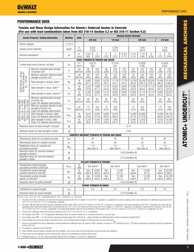
Tension and Shear Design Information For Atomic+ Undercut Anchor in Concrete (For use with load combinations taken from ACI 318-14 Section 5.3 or ACI 318-11 Section 9.2)1
Anchor Property / Setting Information Notation UnitsNominal Anchor Diameter
3/8 inch 1/2 inch 5/8 inch 3/4 inch
Anchor category 1,2 or 3 - 1
outside anchor diameter da[do]8 in. (mm)
0.625 (15.9)
0.750 (19.1)
1.000 (25.4)
1.125 (28.6)
Effective embedment hefin.
(mm)2-3/4 (68)
4 (102)
4 (102)
5 (127)
6-3/4 (171)
4-1/2 (114)
7-1/2 (190)
9 (229)
5 (127)
10 (254)
STEEL STRENGTH IN TENSION AND SHEAR3
Tensile stress area of anchor rod steel Asein.2
(mm2)0.0775
(50)0.1419
(91)0.2260 (146)
0.3345 (216)
AsTM
A36
(fy
≥ 36
ksi)
AsTM
A19
3 Gr
ade
B7
(fy ≥
105
ksi)
Minimum specified yield strength of anchor rod10 fy ksi
(N/mm2)36
(248)105 (723)
36 (248)
105 (723)
105 (723)
36 (248)
105 (723)
105 (723)
36 (248)
105 (723)
Minimum specified ultimate tensile strength of anchor rod10 futa
ksi (N/mm2)
58 (400)
125 (860)
58 (400)
125 (860)
125 (860)
58 (400)
125 (860)
125 (860)
58 (400)
125 (860)
steel strength in tension, static10 Nsalb
(kN)4,495 (20.1)
9,685 (43.2)
8,230 (36.7)
17,735 (79.1)
17,735 (79.1)
13,100 (58.5)
28,250 (126.1)
28,250 (126.1)
19,400 (86.3)
41,810 (186.0)
steel strength in shear, static9,10 Vsalb
(kN)2,245 (10.0)
4,885 (21.7)
4,110 (18.4)
8,855 (39.5)
8,855 (39.5)
6,560 (29.3)
14,110 (63.0)
14,110 (63.0)
9,685 (43.2)
20,875 (93.2)
steel strength in shear, seismic9,10 Veqlb
(kN)2,245 (10.0)
4,885 (21.7)
4,110 (18.4)
8,855 (39.5)
8,855 (39.5)
6,560 (29.3)
14,110 (63.0)
14,110 (63.0)
9,685 (43.2)
20,875 (93.2)
AsTM
A19
3 Gr
ade
B8M
, Cl
ass
1 (fy
>=
30
ksi)
AsTM
A19
3 Gr
ade
B8M
, Cl
ass
2 (fy
>=
95
ksi)
Minimum specified yield strength of anchor rod (Type 316 stainless steel anchor)
fy,ssksi
(N/mm2)30
(205)95
(655)30
(205)95
(655) - 30 (205)
95(655) - 30
(205)95
(655)
Minimum specified ultimate tensile strength of anchor rod(Type 316 stainless steel anchor)
futa,ssksi
(N/mm2)75
(515)105(760)
75 (515)
105(760) - 75
(515)105(760) - 75
(515)105(760)
steel strength in tension, static (Type 316 stainless steel anchor)11 Nsa,ss
lb (kN)
4,415 (19.6)
8,525(37.9)
8,085 (36.0)
15,610(69.4) - 12,880
(57.3)24,860(110.6) - 19,065
(84.8)36,795(163.7)
steel strength in shear, static (Type 316 stainless steel anchor)11 Vsa,ss
lb (kN)
2,210(9.8)
4,265(19.0)
4,045(18.0)
7,805(34.7) - 6,440
(28.6)12,430(55.3) - 9,535
(42.4)18,400(81.8)
reduction factor for steel strength in tension2 f - 0.75
reduction factor for steel strength in shear2 f - 0.65
CONCRETE BREAKOUT STRENGTH IN TENSION AND SHEAR7
Effectiveness factor for uncracked concrete kuncr - 30 30 30 30
Effectiveness factor for cracked concrete kcr - 24 24 24 24Modification factor for cracked and uncracked concrete4 Ψc,n - 1.0
(see note 4)1.0
(see note 4)1.0
(see note 4)1.0
(see note 4)reduction factor for concrete breakout strength in tension2 f - 0.65 (Condition B)
reduction factor for concrete breakout strength in shear2 f - 0.70 (Condition B)
PULLOUT STRENGTH IN TENSION7
Characteristic pullout strength, uncracked concrete (2,500 psi)5 Np,uncr
lb (kN) see note 6 see note 6 see note 6 see note 6
Characteristic pullout strength, cracked concrete (2,500 psi)5 Np,cr
lb (kN)
see note 6
9,000 (40.2)
see note 6
11,500 (51.3)
see note 6
15,000 (67.0)
see note 6
22,000 (98.2)
Characteristic pullout strength, seismic (2,500 psi)5,10 Neq
lb (kN)
see note 6
9,000 (40.2)
see note 6
11,500 (51.3)
see note 6
15,000 (67.0)
see note 6
22,000 (98.2)
reduction factor for pullout strength2 f - 0.65 (Condition B)PRYOUT STRENGTH IN SHEAR7
Coefficient for pryout strength kcp - 2.0 2.0 2.0 2.0
reduction factor for pryout strength2 f - 0.70 (Condition B)
For sI: 1 inch = 25.4 mm, 1 ksi = 6.895 MPa (N/mm2), 1 lbf = 0.0044 kN, 1 in2 = 645 mm2.
1. The data in this table is intended to be used with the design provisions of ACI 318-14 Chapter 17 or ACI 318-11 Appendix D, as applicable; for anchors resisting seismic load combinations the additional requirements of ACI 318-14 17.2.3 or ACI 318-11 D.3.3, as applicable, shall apply.
2. All values of f were determined from the load combinations of IBC section 1605.2, ACI 318-14 section 5.3 or ACI 318-11 section 9.2, as applicable. If the load combinations of ACI 318-11 Appendix C are used, then the appropriate value of f must be determined in accordance with ACI 318-11 D.4.4. For reinforcement that meets ACI 318-14 Chapter 17 or ACI 318-11 Appendix D, as applicable, requirements for Condition A, see ACI 318-14 17.3.3(c) or ACI 318-11 D.4.3(c), as applicable, for the appropriate f factor when the load combinations of IBC section 1605.2, ACI 318-14 section 5.3 or ACI 318-11 section 9.2, as applicable, are used.
3. Anchors are considered a ductile steel element as defined by ACI 318-14 2.3 or ACI 318-11 D.1, as applicable.
4. For all design cases Ψc,n =1.0. The appropriate effectiveness factor for cracked concrete (kcr) or uncracked concrete (kuncr) must be used.
5. For all design cases Ψc,p =1.0. For concrete compressive strength greater than 2,500 psi Npn = (pullout strength from table)*(specified concrete compressive strength/2,500)0.5.
6. Pullout strength does not control design of indicated anchors. Do not calculate pullout strength for indicated anchor size and embedment.
7. Anchors are permitted to be used in lightweight concrete provided the modification factor λa equal to 0.8λ is applied to all values of f'c√ affecting Nn and Vn. λ shall be determined in accordance with the corresponding version of ACI 318.
8. The notation in brackets is for the 2006 IBC.
9. shear strength values are based on standard (pre-set) installation, and must be used for both standard (pre-set) and through-bolt installations.
10. These values are only applicable to carbon steel anchors; values are not established for stainless steel anchors.
11. Calculated using futa,ss = 57 ksi (1.9fy) in accordance with ACI 318-14 Chapter 17 or ACI 318-11 Appendix D.

TECHNICAL GUIDE – MECHANICAL ANCHors ©
2021 DEWALT – rEV. D
ANCHORS & FASTENERSperformanCe Data
Mec
han
ical a
ncho
rs
6
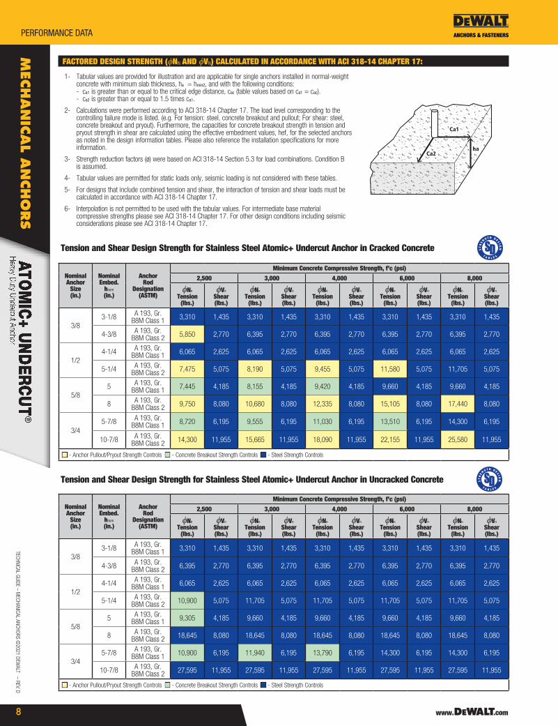
FACTORED DESIGN STRENGTH (fNn AND fVn) CALCULATED IN ACCORDANCE WITH ACI 318-14 CHAPTER 17:
1- Tabular values are provided for illustration and are applicable for single anchors installed in normal-weight concrete with minimum slab thickness, ha = hmin2, and with the following conditions: - ca1 is greater than or equal to the critical edge distance, cac (table values based on ca1 = cac). - ca2 is greater than or equal to 1.5 times ca1.
2- Calculations were performed according to ACI 318-14 Chapter 17. The load level corresponding to the controlling failure mode is listed. (e.g. For tension: steel, concrete breakout and pullout; For shear: steel, concrete breakout and pryout). Furthermore, the capacities for concrete breakout strength in tension and pryout strength in shear are calculated using the effective embedment values, hef, for the selected anchors as noted in the design information tables. Please also reference the installation specifications for more information.
3- strength reduction factors (ø) were based on ACI 318-14 section 5.3 for load combinations. Condition B is assumed.
4- Tabular values are permitted for static loads only, seismic loading is not considered with these tables.
5- For designs that include combined tension and shear, the interaction of tension and shear loads must be calculated in accordance with ACI 318-14 Chapter 17.
6- Interpolation is not permitted to be used with the tabular values. For intermediate base material compressive strengths please see ACI 318-14 Chapter 17. For other design conditions including seismic considerations please see ACI 318-14 Chapter 17.
Ca1
Ca2ha
Tension and Shear Design Strength for Carbon Steel Atomic+ Undercut in Cracked Concrete
Nominal Anchor
Size (in.)
Nominal Embed.
hnom (in.)
AnchorRod
Designation(ASTM)
Minimum Concrete Compressive Strength, f’c (psi)
2,500 3,000 4,000 6,000 8,000
fNn Tension
(lbs.)
fVn Shear (lbs.)
fNn Tension
(lbs.)
fVn Shear (lbs.)
fNn Tension
(lbs.)
fVn Shear (lbs.)
fNn Tension
(lbs.)
fVn Shear (lbs.)
fNn Tension
(lbs.)
fVn Shear (lbs.)
3/83-1/8 A 36 3,370 1,460 3,370 1,460 3,370 1,460 3,370 1,460 3,370 1,460
4-3/8 A 193, Gr. B7 5,850 3,175 6,410 3,175 7,265 3,175 7,265 3,175 7,265 3,175
1/2
4-1/4 A 36 6,175 2,670 6,175 2,670 6,175 2,670 6,175 2,670 6,175 2,670
5-1/4 A 193, Gr. B7 7,475 5,755 8,190 5,755 9,455 5,755 11,580 5,755 13,300 5,755
7 A 193, Gr. B7 7,475 5,755 8,190 5,755 9,455 5,755 11,580 5,755 13,300 5,755
5/8
5 A 36 7,445 4,265 8,155 4,265 9,420 4,265 9,825 4,265 9,825 4,265
8 A 193, Gr. B7 9,750 9,170 10,680 9,170 12,335 9,170 15,105 9,170 17,440 9,170
9-1/2 A 193, Gr. B7 9,750 9,170 10,680 9,170 12,335 9,170 15,105 9,170 17,440 9,170
3/45-7/8 A 36 8,720 6,410 9,555 6,410 11,030 6,410 13,510 6,410 14,550 6,410
10-7/8 A 193, Gr. B7 14,300 13,570 15,665 13,570 18,090 13,570 22,155 13,570 25,580 13,570
■ - Anchor Pullout/Pryout strength Controls ■ - Concrete Breakout strength Controls ■ - steel strength Controls
Tension and Shear Design Strength for Carbon Steel Atomic+ Undercut in Uncracked Concrete
Nominal Anchor
Size (in.)
Nominal Embed.
hnom (in.)
AnchorRod
Designation(ASTM)
Minimum Concrete Compressive Strength, f’c (psi)
2,500 3,000 4,000 6,000 8,000
fNn Tension
(lbs.)
fVn Shear (lbs.)
fNn Tension
(lbs.)
fVn Shear (lbs.)
fNn Tension
(lbs.)
fVn Shear (lbs.)
fNn Tension
(lbs.)
fVn Shear (lbs.)
fNn Tension
(lbs.)
fVn Shear (lbs.)
3/83-1/8 A 36 3,370 1,460 3,370 1,460 3,370 1,460 3,370 1,460 3,370 1,460
4-3/8 A 193, Gr. B7 7,265 3,175 7,265 3,175 7,265 3,175 7,265 3,175 7,265 3,175
1/2
4-1/4 A 36 6,175 2,670 6,175 2,670 6,175 2,670 6,175 2,670 6,175 2,670
5-1/4 A 193, Gr. B7 10,900 5,755 11,940 5,755 13,300 5,755 13,300 5,755 13,300 5,755
7 A 193, Gr. B7 13,300 5,755 13,300 5,755 13,300 5,755 13,300 5,755 13,300 5,755
5/8
5 A 36 9,305 4,265 9,825 4,265 9,825 4,265 9,825 4,265 9,825 4,265
8 A 193, Gr. B7 20,025 9,170 21,190 9,170 21,190 9,170 21,190 9,170 21,190 9,170
9-1/2 A 193, Gr. B7 21,190 9,170 21,190 9,170 21,190 9,170 21,190 9,170 21,190 9,170
3/45-7/8 A 36 10,900 6,410 11,940 6,410 13,790 6,410 14,550 6,410 14,550 6,410
10-7/8 A 193, Gr. B7 30,830 13,570 31,360 13,570 31,360 13,570 31,360 13,570 31,360 13,570
■ - Anchor Pullout/Pryout strength Controls ■ - Concrete Breakout strength Controls ■ - steel strength Controls
TECH
NICA
L GU
IDE
– M
ECHA
NICA
L AN
CHor
s ©
2021
DEW
ALT
– r
EV. D
ANCHORS & FASTENERS performanCe Data
7
Mec
han
ical
an
cho
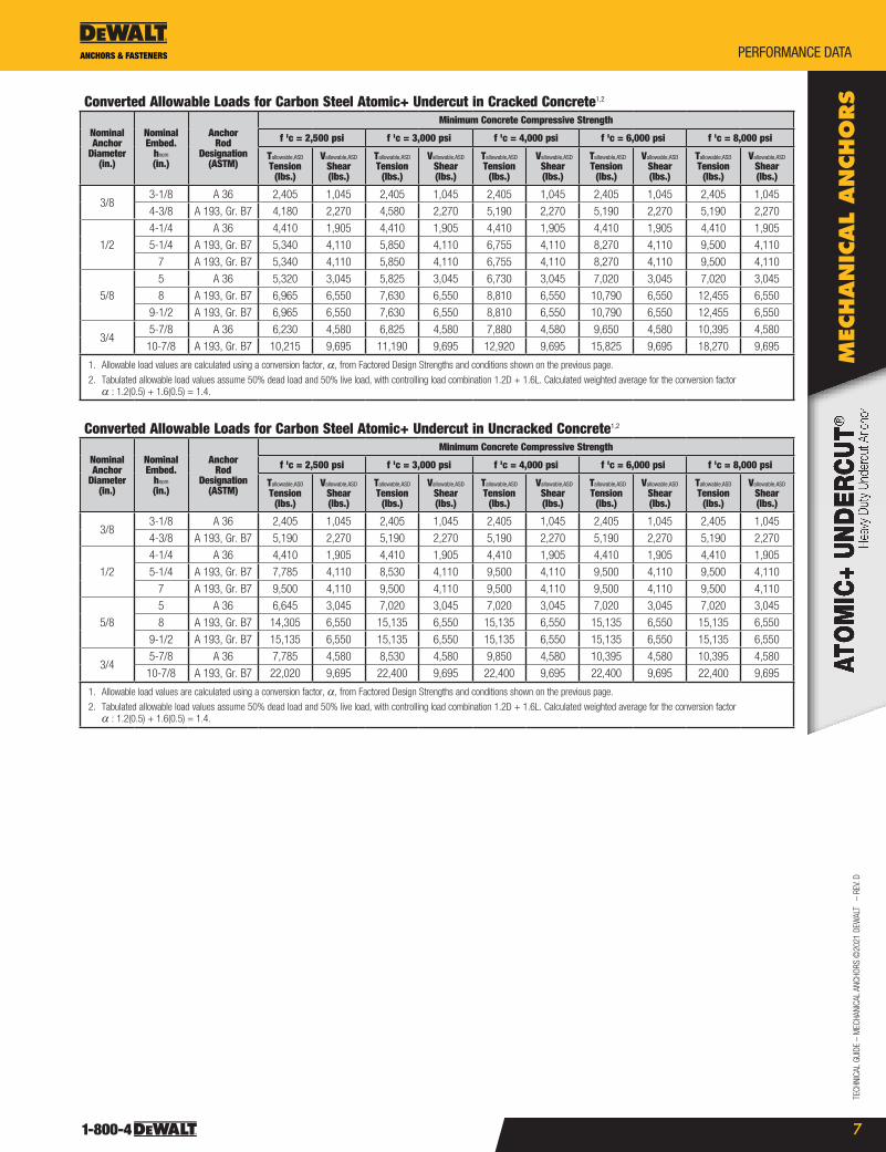
rsConverted Allowable Loads for Carbon Steel Atomic+ Undercut in Cracked Concrete1,2
Nominal Anchor
Diameter(in.)
NominalEmbed.
hnom
(in.)
AnchorRod
Designation(ASTM)
Minimum Concrete Compressive Strength
f 'c = 2,500 psi f 'c = 3,000 psi f 'c = 4,000 psi f 'c = 6,000 psi f 'c = 8,000 psi
Tallowable,aSD
Tension(lbs.)
Vallowable,aSD
Shear(lbs.)
Tallowable,aSD
Tension(lbs.)
Vallowable,aSD
Shear(lbs.)
Tallowable,aSD
Tension(lbs.)
Vallowable,aSD
Shear(lbs.)
Tallowable,aSD
Tension(lbs.)
Vallowable,aSD
Shear(lbs.)
Tallowable,aSD
Tension(lbs.)
Vallowable,aSD
Shear(lbs.)
3/83-1/8 A 36 2,405 1,045 2,405 1,045 2,405 1,045 2,405 1,045 2,405 1,045
4-3/8 A 193, Gr. B7 4,180 2,270 4,580 2,270 5,190 2,270 5,190 2,270 5,190 2,270
1/2
4-1/4 A 36 4,410 1,905 4,410 1,905 4,410 1,905 4,410 1,905 4,410 1,905
5-1/4 A 193, Gr. B7 5,340 4,110 5,850 4,110 6,755 4,110 8,270 4,110 9,500 4,110
7 A 193, Gr. B7 5,340 4,110 5,850 4,110 6,755 4,110 8,270 4,110 9,500 4,110
5/8
5 A 36 5,320 3,045 5,825 3,045 6,730 3,045 7,020 3,045 7,020 3,045
8 A 193, Gr. B7 6,965 6,550 7,630 6,550 8,810 6,550 10,790 6,550 12,455 6,550
9-1/2 A 193, Gr. B7 6,965 6,550 7,630 6,550 8,810 6,550 10,790 6,550 12,455 6,550
3/45-7/8 A 36 6,230 4,580 6,825 4,580 7,880 4,580 9,650 4,580 10,395 4,580
10-7/8 A 193, Gr. B7 10,215 9,695 11,190 9,695 12,920 9,695 15,825 9,695 18,270 9,695
1. Allowable load values are calculated using a conversion factor, a, from Factored Design strengths and conditions shown on the previous page.
2. Tabulated allowable load values assume 50% dead load and 50% live load, with controlling load combination 1.2D + 1.6L. Calculated weighted average for the conversion factor a : 1.2(0.5) + 1.6(0.5) = 1.4.
Converted Allowable Loads for Carbon Steel Atomic+ Undercut in Uncracked Concrete1,2
Nominal Anchor
Diameter(in.)
NominalEmbed.
hnom
(in.)
AnchorRod
Designation(ASTM)
Minimum Concrete Compressive Strength
f 'c = 2,500 psi f 'c = 3,000 psi f 'c = 4,000 psi f 'c = 6,000 psi f 'c = 8,000 psi
Tallowable,aSD
Tension(lbs.)
Vallowable,aSD
Shear(lbs.)
Tallowable,aSD
Tension(lbs.)
Vallowable,aSD
Shear(lbs.)
Tallowable,aSD
Tension(lbs.)
Vallowable,aSD
Shear(lbs.)
Tallowable,aSD
Tension(lbs.)
Vallowable,aSD
Shear(lbs.)
Tallowable,aSD
Tension(lbs.)
Vallowable,aSD
Shear(lbs.)
3/83-1/8 A 36 2,405 1,045 2,405 1,045 2,405 1,045 2,405 1,045 2,405 1,045
4-3/8 A 193, Gr. B7 5,190 2,270 5,190 2,270 5,190 2,270 5,190 2,270 5,190 2,270
1/2
4-1/4 A 36 4,410 1,905 4,410 1,905 4,410 1,905 4,410 1,905 4,410 1,905
5-1/4 A 193, Gr. B7 7,785 4,110 8,530 4,110 9,500 4,110 9,500 4,110 9,500 4,110
7 A 193, Gr. B7 9,500 4,110 9,500 4,110 9,500 4,110 9,500 4,110 9,500 4,110
5/8
5 A 36 6,645 3,045 7,020 3,045 7,020 3,045 7,020 3,045 7,020 3,045
8 A 193, Gr. B7 14,305 6,550 15,135 6,550 15,135 6,550 15,135 6,550 15,135 6,550
9-1/2 A 193, Gr. B7 15,135 6,550 15,135 6,550 15,135 6,550 15,135 6,550 15,135 6,550
3/45-7/8 A 36 7,785 4,580 8,530 4,580 9,850 4,580 10,395 4,580 10,395 4,580
10-7/8 A 193, Gr. B7 22,020 9,695 22,400 9,695 22,400 9,695 22,400 9,695 22,400 9,695
1. Allowable load values are calculated using a conversion factor, a, from Factored Design strengths and conditions shown on the previous page.
2. Tabulated allowable load values assume 50% dead load and 50% live load, with controlling load combination 1.2D + 1.6L. Calculated weighted average for the conversion factor a : 1.2(0.5) + 1.6(0.5) = 1.4.
TECHNICAL GUIDE – MECHANICAL ANCHors ©
2021 DEWALT – rEV. D
ANCHORS & FASTENERSperformanCe Data
Mec
han
ical a
ncho
rs
8
FACTORED DESIGN STRENGTH (fNn AND fVn) CALCULATED IN ACCORDANCE WITH ACI 318-14 CHAPTER 17:
1- Tabular values are provided for illustration and are applicable for single anchors installed in normal-weight concrete with minimum slab thickness, ha = hmin2, and with the following conditions: - ca1 is greater than or equal to the critical edge distance, cac (table values based on ca1 = cac). - ca2 is greater than or equal to 1.5 times ca1.
2- Calculations were performed according to ACI 318-14 Chapter 17. The load level corresponding to the controlling failure mode is listed. (e.g. For tension: steel, concrete breakout and pullout; For shear: steel, concrete breakout and pryout). Furthermore, the capacities for concrete breakout strength in tension and pryout strength in shear are calculated using the effective embedment values, hef, for the selected anchors as noted in the design information tables. Please also reference the installation specifications for more information.
3- strength reduction factors (ø) were based on ACI 318-14 section 5.3 for load combinations. Condition B is assumed.
4- Tabular values are permitted for static loads only, seismic loading is not considered with these tables.
5- For designs that include combined tension and shear, the interaction of tension and shear loads must be calculated in accordance with ACI 318-14 Chapter 17.
6- Interpolation is not permitted to be used with the tabular values. For intermediate base material compressive strengths please see ACI 318-14 Chapter 17. For other design conditions including seismic considerations please see ACI 318-14 Chapter 17.
Ca1
Ca2ha
Tension and Shear Design Strength for Stainless Steel Atomic+ Undercut Anchor in Cracked Concrete
Nominal Anchor
Size (in.)
Nominal Embed.
hnom (in.)
AnchorRod
Designation(ASTM)
Minimum Concrete Compressive Strength, f’c (psi)
2,500 3,000 4,000 6,000 8,000
fNn Tension
(lbs.)
fVn Shear (lbs.)
fNn Tension
(lbs.)
fVn Shear (lbs.)
fNn Tension
(lbs.)
fVn Shear (lbs.)
fNn Tension
(lbs.)
fVn Shear (lbs.)
fNn Tension
(lbs.)
fVn Shear (lbs.)
3/83-1/8 A 193, Gr.
B8M Class 1 3,310 1,435 3,310 1,435 3,310 1,435 3,310 1,435 3,310 1,435
4-3/8 A 193, Gr. B8M Class 2 5,850 2,770 6,395 2,770 6,395 2,770 6,395 2,770 6,395 2,770
1/24-1/4 A 193, Gr.
B8M Class 1 6,065 2,625 6,065 2,625 6,065 2,625 6,065 2,625 6,065 2,625
5-1/4 A 193, Gr. B8M Class 2 7,475 5,075 8,190 5,075 9,455 5,075 11,580 5,075 11,705 5,075
5/85 A 193, Gr.
B8M Class 1 7,445 4,185 8,155 4,185 9,420 4,185 9,660 4,185 9,660 4,185
8 A 193, Gr. B8M Class 2 9,750 8,080 10,680 8,080 12,335 8,080 15,105 8,080 17,440 8,080
3/45-7/8 A 193, Gr.
B8M Class 1 8,720 6,195 9,555 6,195 11,030 6,195 13,510 6,195 14,300 6,195
10-7/8 A 193, Gr. B8M Class 2 14,300 11,955 15,665 11,955 18,090 11,955 22,155 11,955 25,580 11,955
■ - Anchor Pullout/Pryout strength Controls ■ - Concrete Breakout strength Controls ■ - steel strength Controls
Tension and Shear Design Strength for Stainless Steel Atomic+ Undercut Anchor in Uncracked Concrete
Nominal Anchor
Size (in.)
Nominal Embed.
hnom (in.)
AnchorRod
Designation(ASTM)
Minimum Concrete Compressive Strength, f’c (psi)
2,500 3,000 4,000 6,000 8,000
fNn Tension
(lbs.)
fVn Shear (lbs.)
fNn Tension
(lbs.)
fVn Shear (lbs.)
fNn Tension
(lbs.)
fVn Shear (lbs.)
fNn Tension
(lbs.)
fVn Shear (lbs.)
fNn Tension
(lbs.)
fVn Shear (lbs.)
3/83-1/8 A 193, Gr.
B8M Class 1 3,310 1,435 3,310 1,435 3,310 1,435 3,310 1,435 3,310 1,435
4-3/8 A 193, Gr. B8M Class 2 6,395 2,770 6,395 2,770 6,395 2,770 6,395 2,770 6,395 2,770
1/24-1/4 A 193, Gr.
B8M Class 1 6,065 2,625 6,065 2,625 6,065 2,625 6,065 2,625 6,065 2,625
5-1/4 A 193, Gr. B8M Class 2 10,900 5,075 11,705 5,075 11,705 5,075 11,705 5,075 11,705 5,075
5/85 A 193, Gr.
B8M Class 1 9,305 4,185 9,660 4,185 9,660 4,185 9,660 4,185 9,660 4,185
8 A 193, Gr. B8M Class 2 18,645 8,080 18,645 8,080 18,645 8,080 18,645 8,080 18,645 8,080
3/45-7/8 A 193, Gr.
B8M Class 1 10,900 6,195 11,940 6,195 13,790 6,195 14,300 6,195 14,300 6,195
10-7/8 A 193, Gr. B8M Class 2 27,595 11,955 27,595 11,955 27,595 11,955 27,595 11,955 27,595 11,955
■ - Anchor Pullout/Pryout strength Controls ■ - Concrete Breakout strength Controls ■ - steel strength Controls

TECH
NICA
L GU
IDE
– M
ECHA
NICA
L AN
CHor
s ©
2021
DEW
ALT
– r
EV. D
ANCHORS & FASTENERS performanCe Data
9
Mec
han
ical
an
cho
rsConverted Allowable Loads for Stainless Steel Atomic+ Undercut in Cracked Concrete1,2
Nominal Anchor
Diameter(in.)
NominalEmbed.
hnom
(in.)
AnchorRod
Designation(ASTM)
Minimum Concrete Compressive Strength
f 'c = 2,500 psi f 'c = 3,000 psi f 'c = 4,000 psi f 'c = 6,000 psi f 'c = 8,000 psi
Tallowable,aSD
Tension(lbs.)
Vallowable,aSD
Shear(lbs.)
Tallowable,aSD
Tension(lbs.)
Vallowable,aSD
Shear(lbs.)
Tallowable,aSD
Tension(lbs.)
Vallowable,aSD
Shear(lbs.)
Tallowable,aSD
Tension(lbs.)
Vallowable,aSD
Shear(lbs.)
Tallowable,aSD
Tension(lbs.)
Vallowable,aSD
Shear(lbs.)
3/83-1/8 A 193, Gr.
B8M Class 1 2,365 1,025 2,365 1,025 2,365 1,025 2,365 1,025 2,365 1,025
4-3/8 A 193, Gr. B8M Class 2 4,180 1,980 4,570 1,980 4,570 1,980 4,570 1,980 4,570 1,980
1/24-1/4 A 193, Gr.
B8M Class 1 4,330 1,875 4,330 1,875 4,330 1,875 4,330 1,875 4,330 1,875
5-1/4 A 193, Gr. B8M Class 2 5,340 3,625 5,850 3,625 6,755 3,625 8,270 3,625 8,360 3,625
5/85 A 193, Gr.
B8M Class 1 5,320 2,990 5,825 2,990 6,730 2,990 6,900 2,990 6,900 2,990
8 A 193, Gr. B8M Class 2 6,965 5,770 7,630 5,770 8,810 5,770 10,790 5,770 12,455 5,770
3/45-7/8 A 193, Gr.
B8M Class 1 6,230 4,425 6,825 4,425 7,880 4,425 9,650 4,425 10,215 4,425
10-7/8 A 193, Gr. B8M Class 2 10,215 8,540 11,190 8,540 12,920 8,540 15,825 8,540 18,270 8,540
1. Allowable load values are calculated using a conversion factor, a, from Factored Design strengths and conditions shown on the previous page.
2. Tabulated allowable load values assume 50% dead load and 50% live load, with controlling load combination 1.2D + 1.6L. Calculated weighted average for the conversion factor a : 1.2(0.5) + 1.6(0.5) = 1.4.
Converted Allowable Loads for Stainless Steel Atomic+ Undercut in Uncracked Concrete1,2
Nominal Anchor
Diameter(in.)
NominalEmbed.
hnom
(in.)
AnchorRod
Designation(ASTM)
Minimum Concrete Compressive Strength
f 'c = 2,500 psi f 'c = 3,000 psi f 'c = 4,000 psi f 'c = 6,000 psi f 'c = 8,000 psi
Tallowable,aSD
Tension(lbs.)
Vallowable,aSD
Shear(lbs.)
Tallowable,aSD
Tension(lbs.)
Vallowable,aSD
Shear(lbs.)
Tallowable,aSD
Tension(lbs.)
Vallowable,aSD
Shear(lbs.)
Tallowable,aSD
Tension(lbs.)
Vallowable,aSD
Shear(lbs.)
Tallowable,aSD
Tension(lbs.)
Vallowable,aSD
Shear(lbs.)
3/83-1/8 A 193, Gr.
B8M Class 1 2,365 1,025 2,365 1,025 2,365 1,025 2,365 1,025 2,365 1,025
4-3/8 A 193, Gr. B8M Class 2 4,570 1,980 4,570 1,980 4,570 1,980 4,570 1,980 4,570 1,980
1/24-1/4 A 193, Gr.
B8M Class 1 4,330 1,875 4,330 1,875 4,330 1,875 4,330 1,875 4,330 1,875
5-1/4 A 193, Gr. B8M Class 2 7,785 3,625 8,360 3,625 8,360 3,625 8,360 3,625 8,360 3,625
5/85 A 193, Gr.
B8M Class 1 6,645 2,990 6,900 2,990 6,900 2,990 6,900 2,990 6,900 2,990
8 A 193, Gr. B8M Class 2 13,320 5,770 13,320 5,770 13,320 5,770 13,320 5,770 13,320 5,770
3/45-7/8 A 193, Gr.
B8M Class 1 7,785 4,425 8,530 4,425 9,850 4,425 10,215 4,425 10,215 4,425
10-7/8 A 193, Gr. B8M Class 2 19,710 8,540 19,710 8,540 19,710 8,540 19,710 8,540 19,710 8,540
1. Allowable load values are calculated using a conversion factor, a, from Factored Design strengths and conditions shown on the previous page.
2. Tabulated allowable load values assume 50% dead load and 50% live load, with controlling load combination 1.2D + 1.6L. Calculated weighted average for the conversion factor a : 1.2(0.5) + 1.6(0.5) = 1.4.
TECHNICAL GUIDE – MECHANICAL ANCHors ©
2021 DEWALT – rEV. D
ANCHORS & FASTENERSorDerInG InformatIon
Mec
han
ical a
ncho
rs
10
ORDERING INFORMATION
Atomic+ Undercut Anchor Zinc Plated Carbon Steel
Cat. No. Anchor Rod ASTM DesignationNominal Anchor
Diameter
Anchor Outside
DiameterOverall Length
Required Undercut Bit
(Cat. No.)
Required Stop Bit
(Cat. No.)Anchor Type Std. Box
03100sD AsTM A36 3/8" 5/8" 5-1/2"
03200sD
03220sD standard 20
03102sD AsTM A36 3/8" 5/8" 5-1/2" * Through Bolt 20
03104sD AsTM A193 Gr. B7 3/8" 5/8" 6-3/4" 03221sD standard 20
03106sD AsTM A193 Gr. B7 3/8" 5/8" 6-3/4" * Through Bolt 20
03108sD AsTM A36 1/2" 3/4" 7"
03201sD
03222sD standard 15
03110sD AsTM A36 1/2" 3/4" 7" * Through Bolt 15
03112sD AsTM A193 Gr. B7 1/2" 3/4" 8" 03223sD standard 15
03114sD AsTM A193 Gr. B7 1/2" 3/4" 8" * Through Bolt 15
03116sD AsTM A193 Gr. B7 1/2" 3/4" 9-3/4" 03224sD standard 15
03118sD AsTM A193 Gr. B7 1/2" 3/4" 9-3/4" * Through Bolt 15
03120sD AsTM A36 5/8" 1" 7-3/4"
03202sD
03225sD standard 10
03122sD AsTM A36 5/8" 1" 7-3/4" * Through Bolt 10
03124sD AsTM A193 Gr. B7 5/8" 1" 10-3/4" 03226sD standard 10
03126sD AsTM A193 Gr. B7 5/8" 1" 10-3/4" * Through Bolt 10
03128sD AsTM A193 Gr. B7 5/8" 1" 12-1/4" 03227sD standard 10
03130sD AsTM A193 Gr. B7 5/8" 1" 12-1/4" * Through Bolt 10
03132sD AsTM A36 3/4" 1-1/8" 8-5/8"
03203sD
03228sD standard 8
03134sD AsTM A36 3/4" 1-1/8" 8-5/8" * Through Bolt 8
03136sD AsTM A193 Gr. B7 3/4" 1-1/8" 13-5/8" 03229sD standard 8
03138sD AsTM A193 Gr. B7 3/4" 1-1/8" 13-5/8" * Through Bolt 8
For availability of all anchor lengths please contact DEWALT.
*Contact DEWALT for appropriate drilling method and hardware
Atomic+ Undercut Anchor Type 316 Stainless Steel
Cat. No. Anchor Rod ASTM DesignationNominal Anchor
Diameter
Anchor Outside
DiameterOverall Length
Required Undercut Bit
(Cat. No.)
Required Stop Bit
(Cat. No.)Anchor Type Std. Box
03600sD AsTM A193, Grade B8M, Class 1 3/8" 5/8" 5-1/2"
03200sD
03220sD standard 20
03602sD AsTM A193, Grade B8M, Class 1 3/8" 5/8" 5-1/2" * Through Bolt 20
03603sD AsTM A193, Grade B8M, Class 2 3/8" 5/8" 6-3/4" 03221sD standard 20
03605sD AsTM A193, Grade B8M, Class 2 3/8" 5/8" 6-3/4" * Through Bolt 20
03608sD AsTM A193, Grade B8M, Class 1 1/2" 3/4" 7"
03201sD
03222sD standard 15
03610sD AsTM A193, Grade B8M, Class 1 1/2" 3/4" 7" * Through Bolt 15
03609sD AsTM A193, Grade B8M, Class 2 1/2" 3/4" 8" 03223sD standard 15
03613sD AsTM A193, Grade B8M, Class 2 1/2" 3/4" 8" * Through Bolt 15
03620sD AsTM A193, Grade B8M, Class 1 5/8" 1" 7-3/4"
03202sD
03225sD standard 10
03622sD AsTM A193, Grade B8M, Class 1 5/8" 1" 7-3/4" * Through Bolt 10
03635sD AsTM A193, Grade B8M, Class 2 5/8" 1" 10-3/4" 03226sD standard 10
03639sD AsTM A193, Grade B8M, Class 2 5/8" 1" 10-3/4" * Through Bolt 10
03632sD AsTM A193, Grade B8M, Class 1 3/4" 1-1/8" 8-5/8"
03203sD
03228sD standard 8
03634sD AsTM A193, Grade B8M, Class 1 3/4" 1-1/8" 8-5/8" * Through Bolt 8
03648sD AsTM A193, Grade B8M, Class 2 3/4" 1-1/8" 13-5/8" 03229sD standard 8
03649sD AsTM A193, Grade B8M, Class 2 3/4" 1-1/8" 13-5/8" * Through Bolt 8
For availability of all anchor lengths please contact DEWALT.
*Contact DEWALT for appropriate drilling method and hardware
TECH
NICA
L GU
IDE
– M
ECHA
NICA
L AN
CHor
s ©
2021
DEW
ALT
– r
EV. D
ANCHORS & FASTENERS orDerInG InformatIon
11
Mec
han
ical
an
cho
rs
Stop Drill Bits
Cat. No.
Nominal Stop Drill Bit
Diameter
Corresponding Nominal Anchor
DiameterMax. Drill Depth Shank Type Std.
Tube
03220sD 5/8 3/8 3-1/8" sDs 1
03221sD 5/8 3/8 4-3/8" sDs 1
03222sD 3/4 1/2 4-1/4" sDs 1
03223sD 3/4 1/2 5-1/4" sDs 1
03224sD 3/4 1/2 7" sDs 1
03225sD 1 5/8 5" sDs-Max 1
03226sD 1 5/8 8" sDs-Max 1
03227sD 1 5/8 9-1/2" sDs-Max 1
03228sD 1-1/8 3/4 5-13/16" sDs-Max 1
03229sD 1-1/8 3/4 10-13/16" sDs-Max 1
The stop Drill Bit creates a drill hole to the proper depth for standard installations of the Atomic+ Undercut anchor.
(For through bolt applications please contact DEWALT for appropriate drilling method and hardware)
Undercut Drill Bits
Cat. No.
Nominal Undercut Drill Bit Diameter
Corresponding Nominal Anchor
DiameterMaximum Depth
of Hole Shank Type Std. Tube
03200sD 5/8 3/8 9" sDs 1
03201sD 3/4 1/2 10-1/4" sDs 1
03202sD 1 5/8 12-1/4" sDs-Max 1
03203sD 1-1/8 3/4 13-1/2" sDs-Max 1
The Undercut Drill Bit has a unique design that enlarges the bottom of the drill hole creating a reverse cone sized to receive the Atomic+ Undercut anchor.
Setting Sleeve for Undercut AnchorsCat.. No. Corresponding Nominal Anchor Diameter Std.
Box
03210sD 3/8 1
03211sD 1/2 1
03218sD 5/8 1
03213sD 3/4 1
Replacement Blade Assemblies for Undercut Drill BitCat.. No. Description Std.
Tube
03205sD Atomic+ (3/8") Cutter Blade - 5/8" 1
03206sD Atomic+ (1/2") Cutter Blade - 3/4" 1
03208sD Atomic+ (5/8") Cutter Blade - 1" 1
03209sD Atomic+ (3/4") Cutter Blade - 1-1/8" 1
Replacement Bow Jaws for Undercut Drill BitCat.. No. Description Std.
Tube
03212sD 3/8" Bow Jaw for 5/8" Hole 1
03215sD 1/2" Bow Jaw for 3/4" Hole 1
03216sD 5/8" Bow Jaw for 1" Hole 1
03217sD 3/4" Bow Jaw for 1-1/8" Hole 1