general fittings - strut and supply inc general... · 71 material fittings, unless noted, are made...
TRANSCRIPT

71
MATERIALFittings, unless noted, are made from hot-rolled, pickled and oiled steel plates, strip or coil, and conform to ASTM specifications A575, A576, A635, or A36. The fitting steel also meets the physical requirements of ASTM A1011 SS GR 33. The pickling of the steel produces a smooth surface free from scale.
Many fittings are also available in stainless steel, aluminum and fiberglass. Consult factory for ordering information.
FINISHESFittings are available in:
Perma-Green III (GR),
Electro-galvanized (EG), conforming to ASTM B633 Type III SC1;
Hot-dipped galvanized (HG), conforming to ASTM A123 or A153 and
Plain (PL).
APPLICATIONAll parts drawings illustrate only one application of each fitting. In most cases many other applications are possible. The channels shown in the illustrations are P1000, 15⁄8" square, except where noted otherwise.
All 9⁄16" diameter holes use 1⁄2" x 15⁄16" hex head cap screws and 1⁄2" nuts – P1010, P4010 or P5510 – depending on the channel used. Nuts and bolts are not included with the fitting and must be ordered separately.
DESIGN BOLT TORQUE
SET SCREW TORQUE
Note: Caution should be taken not to overtighten the set screw
DIMENSIONSImperial dimensions are illustrated in inches. Metric dimensions are shown in parenthesis or as noted. Unless noted, all metric dimensions are in millimeters and rounded to one decimal place.
DESIGN LOADDesign load data, where shown, is based on the ultimate strength of the connection with a safety factor of 2.5, unless otherwise noted.
BEAM CLAMPSClamps are designed to be used with W, M, S and HP Shape beams, Standard C and Miscellaneous MC Channels, Angles and Structural Tees. Clamps must be used in pairs where indicated. For beam clamps with HG finish, standard hardware is EG finish. For optional stainless steel hardware, please contact the factory for availability.
GENERAL FITTINGSFlat Plate Fittings .................................................................75-76
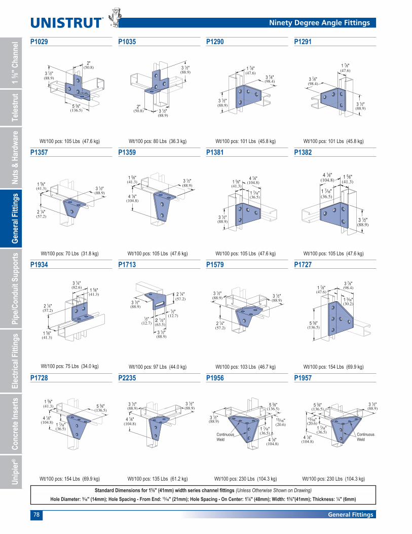
Ninety Degree Fittings.........................................................76-79
Angular Fittings ........................................................................ 79
“Z” Shape Fittings ..................................................................... 80
“U” Shape Fittings ...............................................................81-82
Wing Shape Fittings ............................................................82-84
Post Bases .................................................................................. 84
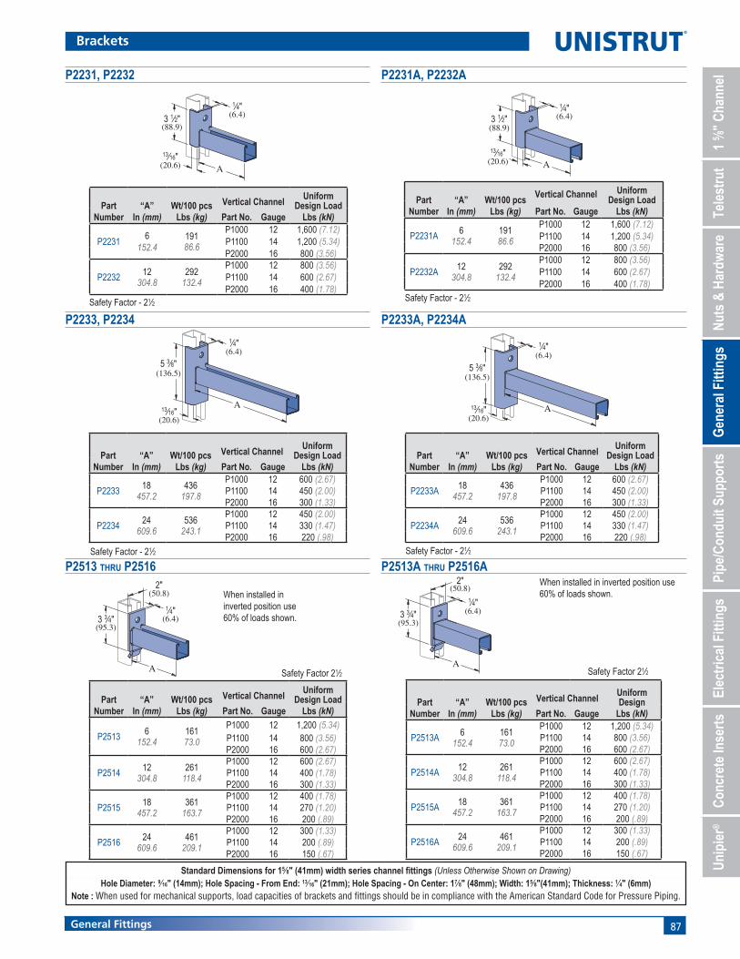
Brackets ................................................................................84-87
Brace Fittings ............................................................................. 88
Beam Clamps ........................................................................89-96
Trolleys ....................................................................................... 96
Special Application Fittings .................................................97-98
Seismic Retrofit Fittings.....................................................98-100
GENERAL FITTINGS

72 General Fittings
General Fittings Pictorial Index
P2469-Pg 80P3045-Pg 80P5560-Pg 80 P4045-Pg 80P3345-Pg 80 P5545-Pg 80P2360-Pg 80P1736-Pg 80P1730-Pg 80 P1734-Pg 80P1479A-Pg 80
"U" Shape Fittings
P4376A-Pg 81 P1377-Pg 81P1363A-Pg 81P1320-Pg 81P2800-Pg 81 P4376-Pg 81P1376-Pg 81 P1376A-Pg 81 P1455-Pg 81P1047-Pg 81 P3047-Pg 81 P4047-Pg 81
P1383-Pg 82 P1732-Pg 82P5547-Pg 81 P1044-Pg 82 P1973-Pg 82P2473-Pg 82 P4043-Pg 82P5543-Pg 82P2237-Pg 82 P1043A-Pg 82P1048-Pg 82 P1737-Pg 82
P2328-Pg 82P2326-Pg 82 P2329-Pg 82
P1062-Pg 75 P1959-Pg 75 P2862-Pg 75 P1065-Pg 75 P1924-Pg 75 P2325-Pg 75 P2324-Pg 75 P1066-Pg 75 P1925-Pg 75 P1067-Pg 75 P2079-Pg 75 P1941-Pg 75 P1036-Pg 75
P1380 A-Pg 75 P1334-Pg 75 P1380-Pg 75 P1873-Pg 76 P1031-Pg 76 P1028-Pg 76 P1356-Pg 76 P1358-Pg 76 P1726-Pg 76 P1953-Pg 76 P1950-Pg 76 P1962-Pg 76
P2626-Pg 76 P1026-Pg 76 P1723-Pg 76 P1068-Pg 76 P1281-Pg 76 P1315-Pg 76 P1538A-Pg 77P1458-Pg 76 P1750-Pg 77 P1747-Pg 77P1498-Pg 77 P1821-Pg 77P1326-Pg 77
P1325-Pg 77 P1823-Pg 77P1822-Pg 77 P1033-Pg 77P1346-Pg 77 P1290-Pg 78 P1291-Pg 78P1038- Pg 77P1037-Pg 77 P1029-Pg 78P1034-Pg 77 P1035-Pg 78
P1357-Pg 78 P1359-Pg 78 P2235-Pg 78 P1956-Pg 78P1727-Pg 78 P1728-Pg 78P1382- Pg 78P1381-Pg 78 P1713-Pg 78P1934-Pg 78 P1579-Pg 78 P1957-Pg 78
Angle Fittings
"Z" Shape Fittings
Flat Plate Fittings
P1347-Pg 80P1045-Pg 80 P1454-Pg 80P1453-Pg 80P2101-Pg 79 P1186-Pg 79 P2260-Pg 79P2484-Pg 79 P1130-Pg 79P2484W-Pg 79 P1546-Pg 79

73General Fittings
General Fittings Pictorial Index
Wing Shape Fittings
Post Bases
P2223-Pg 83 P2224-Pg 83P2472-Pg 83 P2343-Pg 83P1046A-Pg 82 P2341-Pg 83 P2227-Pg 83P2225-Pg 83 P2229-Pg 83P2228-Pg 83 P2345-Pg 83
P2344-Pg 83 P2226-Pg 83P2346-Pg 83 P2347-Pg 83 P2245-Pg 83P2230-Pg 83 P2348-Pg 84 P2453-Pg 84P1887-Pg 84 P2072-Pg 84P2941-Pg 84
Brackets and Brace Fittings
P2073-Pg 84 P2073A-Pg 84P2072A-Pg 84 P2491-Pg 85P1075-Pg 85 P1593-Pg 85P1771-Pg 84P1769-Pg 84 P1775-Pg 85P1773-Pg 85 P1777-Pg 85
P2494-Pg 86 P2500-Pg 86 P2547-Pg 85 P2231-Pg 87P2944-Pg 86 P2542-Pg 86 P2513-Pg 87P2233-Pg 87 P2233A-Pg 87P2231A-Pg 87
Beam Clamps
P2513A-Pg 87 P2458-Pg 88P2452-Pg 88 P2815-Pg 88P2459-Pg 88 P2815D-Pg 88 P2675-Pg 89P2784-Pg 89 PFL2-Pg 89P2897-Pg 89 P2898-Pg 90
P2899-Pg 90 P2398S-Pg 91 P1654A-Pg 91P2679-Pg 91 P1648S-Pg 91P2676-Pg 90 P2677-Pg 90P2682-Pg 90 P1796S-Pg 92P1271S-Pg 92P2674-Pg 91
P2786-Pg 92P2785-Pg 92 P2868-Pg 93 P2868A-Pg 93 P2868B-Pg 93P2867-Pg 92 P2867A-Pg 92 P2867B-Pg 92P2787-Pg 92 P2824-Pg 92 P2893-Pg 93
P2894-Pg 93 P2895-Pg 93 P2896-Pg 93 P3087-Pg 94 P3088-Pg 94P1379S-Pg 94 P1272S-Pg 94P1386-Pg 94 PFL037-Pg 95PLLC025-Pg 94 PLF3037-Pg 95
Trolley Assemblies Special Applications Fittings
PLF9037-Pg 95 P2749-Pg 96 P2750-Pg 96 P2950-Pg 96 P1834-Pg 96P2751-Pg 96 P2949-Pg 96 P1834A-Pg 96 P1354-Pg 98P1354A-Pg 98P1843-Pg 98 P1201-Pg 97
Seismic Retrofit Fittings
P1944-Pg 97P2354-Pg 97 P1204-Pg 97 P2470-Pg 97 P2454-Pg 97P2655-Pg 97 LS500-Pg 100SPF 200-Pg 98SPF 100-Pg 98 SPF 400-Pg 99SPF 300-Pg 99 LS 410-Pg 100

74 General Fittings
DESIGN LOAD DATA FOR TYPICAL UNISTRUT CHANNEL CONNECTIONS90° Fittings (When used in position shown)
Design Load Data
Note:(1) Both ends of beams supported.(2) Load data is based on P1010 nut and 1 2" bolt.(3) Safety factor = 21 2 based on ultimate strength of connection.
LOADLOAD
LOAD LOAD
LOAD LOAD
LOAD
LOAD
LOADLOAD

75General Fittings
7 1⁄4"(184.2)
9 1⁄8"(231.8)
5 3⁄8"(136.5)
3 1⁄2"(88.9) (82.6)
3 1⁄4"1 5⁄8"(41.3)
7 1⁄8"(181.0)
(92.1)3 5⁄8"
4 7⁄8"(123.8)
(41.3)1 5⁄8"
(41.3)1 5⁄8"
(133.4)5 1⁄4"
3 5⁄8"(92.1)
31⁄2"(88.9)
1 5⁄8"(41.3)
(82.6)3 1⁄4"
1 1⁄2"(38.1) (34.9)
1 3⁄8"
Tapped Hole
1 5⁄8"(41.3)
1 5⁄8" (41.3)
Flat Plate Fittings
(88.9)3 1⁄2"
(88.9)3 1⁄2" 3 1⁄2"
(88.9)
3 1⁄2"(88.9)
5 3⁄8"(136.5)
3 1⁄2"(88.9)
(136.5)5 3⁄8"
3 1⁄2"(88.9)

76 General Fittings
5 3⁄8"(136.5)
(88.9)3 1⁄2"
9 1⁄8"
3 1⁄2"(88.9)
(231.8)
(136.5)5 3⁄8"
(136.5)5 3⁄8"
3 1⁄2"(88.9)
3 1⁄2"(88.9)
(136.5)5 3⁄8"
(136.5)5 3⁄8"
5 3⁄8"(136.5)
9 1⁄8"(231.8)
Flat Plate & Ninety Degree Angle Fittings
5 3⁄8"(136.5)
5 3⁄8"(136.5)
(88.9)3 1⁄2"
5 3⁄8"(136.5)
1 7⁄8"(47.6)
1 7⁄8"(47.6)
3⁄4"(19.1)
1⁄2" - 13 Stud
(57.2)2 1⁄4"
3 1⁄2"(88.9)
2 1⁄8"(54.0)
(54.0)2 1⁄8"
1 7⁄8"(47.6)
(50.8)2"
1 5⁄8"(41.3)
2 1⁄4"(57.2)
1 7⁄8"(47.6)
A
Tapped5⁄16"-18 Thd.
1 5⁄8"(41.3)
1 5⁄8"(41.3)
(47.6)1 7⁄8"
41⁄2"(114.3)
27⁄8"(73.0)
15⁄8"(41.3)

77General Fittings
A
1 7⁄8"(47.6)
B
A
(63.5)2 1⁄2"
1 7⁄8"(47.6)
2 5⁄8"(66.7)
1 5⁄8"(41.3)
(33.3)1 5⁄16"
(38.1)1 1⁄2"
Ninety Degree Angle Fittings
2"(50.8) 3 1⁄2"
(88.9)
(50.8)2"
(136.5)5 3⁄8"
2"(50.8)3 1⁄2"
(88.9)
(88.9)3 1⁄2"
(88.9)3 1⁄2"
2"(50.8)
3 7⁄8"(98.4)
(47.6)1 7⁄8"
(82.6)3 1⁄4"1 7⁄8"
(47.6)
(50.8)2"
(41.3)1 5⁄8"
(82.6)3 1⁄4"
(41.3)1 5⁄8"
1 7⁄8"(47.6)
2"(50.8)4 1⁄8"
(104.8)
(88.9)3 1⁄2"
(36.5)1 7⁄16"
(50.8)2"
(123.8)4 7⁄8"
(41.3)1 5⁄8"
4 1⁄8"(104.8)
1 5⁄8"(41.3)
(36.5)1 7⁄16"
(98.4)3 7⁄8"
1 1⁄2"(38.1)
(66.7)2 5⁄8"
1 5⁄16"(33.3)
78 General Fittings
(63.5)2 1⁄2"
3 1⁄2"(88.9)
3 1⁄2"(88.9)
2 1⁄4"(57.2)
1⁄2"(12.7)
1⁄2"(12.7)
(136.5)5 3⁄8"
(30.2)1 3⁄16"
(98.4)3 7⁄8"
1 7⁄8"(47.6)
(104.8)4 1⁄8"
(41.3)1 5⁄8"
(36.5)1 7⁄16"
(136.5)5 3⁄8"
3 1⁄2"(88.9)
(57.2)2 1⁄4"
(88.9)3 1⁄2"(41.3)
1 5⁄8"
(41.3)1 5⁄8"
(82.6)3 1⁄4"
(57.2)2 1⁄4"
Ninety Degree Angle Fittings
(104.8)4 1⁄8"
1 7⁄16"(36.5)
1 5⁄8"(41.3)
(88.9)3 1⁄2"
(104.8)4 1⁄8"
1 7⁄16"(36.5)
1 5⁄8"(41.3)
(88.9)3 1⁄2"
1 7⁄8"(47.6)
3 7⁄8"(98.4)
3 1⁄2"(88.9)
1 7⁄8"(47.6)
3 7⁄8"(98.4)
(88.9)3 1⁄2"
(88.9)3 1⁄2"
(57.2)2 1⁄4"
1 5⁄8"(41.3)
(41.3)1 5⁄8"
4 1⁄8"(104.8)
3 1⁄2"(88.9)
2"(50.8)
(88.9)3 1⁄2"
(88.9)3 1⁄2"
(50.8)2"
5 3⁄8"(136.5)
(88.9)3 1⁄2"
(20.6)13⁄16"
(136.5)5 3⁄8"
(88.9)3 1⁄2"
(36.5)1 7⁄16"
4 1⁄8"(104.8)
Continuous Weld
(20.6)13⁄16"
(136.5)5 3⁄8"
(88.9)3 1⁄2"
(36.5)1 7⁄16"
4 1⁄8"(104.8)
Continuous Weld
4 1⁄8"(104.8)
3 1⁄2"(88.9) (88.9)
3 1⁄2"

79General Fittings
13⁄16"(20.6)
(101.6)4"
(22.2)7⁄8"
1 9⁄16"(39.7)
(101.6)4"
ContinuousWeld
(63.5)2 1⁄2"
A
B
B
(27.0)1 1⁄16"
1 1⁄16"
(52.4)2 1⁄16"
A (27.0)
(27.0)1 1⁄16"
(27.0)1 1⁄16"
B
C
A
13⁄16"(20.6)
(22.2)7⁄8"
1 9⁄16"(39.7)
(101.6)4"
(101.6)4"
Ninety Degree Angle & Angular Fittings
(47.6)1 7⁄8"
(95.3)3 3⁄4"
A
(38.1)1 1⁄2"
1 1⁄2"(38.1)
B
A
B
3 1⁄2"(88.9)
821 2° 35 8

80 General Fittings
(47.6)1 7⁄8"
(47.6)1 7⁄8"
(88.9)3 1⁄2"
(88.9)3 1⁄2"
(41.3)1 5⁄8"
(41.3)1 5⁄8"
(47.6)1 7⁄8"
(47.6)1 7⁄8"
Tapped5⁄16" - 18 Thd.
Tapped5⁄16" - 18 Thd.
1 7⁄8"
(41.3)1 5⁄8"
(41.3)1 5⁄8"
(47.6)
A
1 5⁄8"(41.3)
“Z” Shape Fittings
(41.3)1 5⁄8"
(41.3)1 5⁄8"(27.0)
1 1⁄16"(54.0)2 1⁄8"
1 5⁄8"(41.3)
(82.6)3 1⁄4"
(47.6)1 7⁄8"
P1001P5000
(6.4)Offset
1⁄4"Splice
(88.1)3 "32
15
(34.9)1 3⁄8"
P3000
1 1⁄16"
3 3⁄4"(95.3)
(27.0)
(20.6)
13⁄16"
9⁄32" (7.1) Hole1⁄8" (3.2) Thick
P1000P1100P2000
(20.6)
13⁄16"
P5500
9⁄32" (7.1) Hole1⁄8" (3.2) Thick
(20.6)13⁄16"
(27.0)1 1⁄16"
(95.3)3 3⁄4"
P4000P4100
(61.9)2 7⁄16"
P5500
1 1⁄16"(27.0)
3 3⁄4"(95.3) (27.0)
1 1⁄16"(54.0)2 1⁄8"
(123.8)4 7⁄8"
P1001A3 (shown)or P5501
1 1⁄16"(27.0)
(22.2)7⁄8"
3 3⁄4"(95.3)
P3300

81General Fittings
A
1 7⁄8"(47.6)
“U” Shape Fittings
1 7⁄8"(47.6)
(19.1)
3⁄4"
(54.8)2 5⁄32"
1⁄2"-13 Thd.3 1⁄2"(88.9)
P3300P4000P4100
2 7⁄16"(61.9)
(136.5)5 3⁄8"
1 "(42.1)
2132
P55005 5⁄16"(134.9)
1⁄4" (6.4)Offset
1⁄4" (6.4) Plate
1 "
(136.5)5 3⁄8"
(34.9)1 3⁄8"
2132
P3000
(42.1)
(136.5)5 3⁄8"
(20.6)13⁄16"
1 "(42.1)
2132
P3300P4000P4100
(41.3)1 5⁄8"
1 21⁄32"
(136.5)5 3⁄8"
(42.1)7 1⁄4"
A
(184.2)
5 3⁄8"(136.5)
5 3⁄8"(136.5)
P3300P4000P4100
3 1⁄2"(88.9)
15⁄32"
11 Ga.
1 5⁄8"(41.3)
(11.9)

82 General Fittings
5 3⁄8"(136.5)
3 1⁄2"(88.9)
1 7⁄8"(47.6)
1 "(42.1)
2132
P1000 (shown), P1100, P2000, P4001 or P4101
1 5⁄8"(41.3)
1 5⁄8"(41.3)
13⁄16"(20.6)
2 1⁄4"(57.2)
(96.0)
1 7⁄8"
3 25⁄32"
(47.6)
1 1⁄16"(27.0)
1 21⁄32"(42.1)
P1001 (shown),P1101, P2001or P4004
“U” & Wing Shape Fittings
7"(177.8)
(83.3)3 9⁄32"
1 5⁄8"(41.3)
(41.3)1 5⁄8"
P1001A
(47.6)1 7⁄8"
4 7⁄8"(123.8)
P1001A3 (shown)or P5501
(136.5)5 3⁄8"
P1001(shown), P1101,P2001, P4004 or P5000
(82.6)3 1⁄4"1 21⁄32"
(42.1)
7"(177.8)
3 9⁄32"(83.3) (41.3)
1 5⁄8"
P4004 (shown), P1001, P1101, P2001, or P5000
(41.3)1 5⁄8"
5 3⁄8"(136.5)
Tapped5⁄16"-18Thread
(42.1)1 "21
32
(62.7)2 "
(161.1) 1 7⁄8"(47.6)
15 32
6 "1132
P5500
(41.3)1 5⁄8"
(19.1)3⁄4"
(10.3) (93.7)3 11⁄16"
(42.9)1 11⁄16"
All Holes 9⁄32" (7.1) Dia.
13⁄32"
1 5⁄8"(41.3)
B
1 1⁄2"(38.1)
A
5 3⁄8"(136.5)
(42.1)
1 7⁄8"(47.6)
1 "2132
1 "(42.1)
2132
3 1⁄2"
P1001(shown),P1101, P2001, P4004 or P5000
3 1⁄2"(88.9)
(88.9)
5 3⁄8"(136.5)
4 1⁄32"(102.4)
1 7⁄8" 1 5⁄64"(47.6) (27.4)7"
(177.8)
3 1⁄2"(88.9)
1 7⁄8"
P1001(shown),P1101, P2001, P4004 or P5000
3 9⁄32"(83.3)
(47.6)

83General Fittings
Wing Shape Fittings
2"(50.8)
(41.3)
Note: Holeon back flangenot shown
1 5⁄8"
(47.6)1 7⁄8"
(42.1)1 "21
32 (88.9)3 1⁄2"
(95.3)3 3⁄4"
2"(50.8)
(47.6)1 7⁄8"
3 7⁄8"(98.4)
1 7⁄8"(47.6)
3 7⁄8"(98.4)
3 3⁄4"(95.3)
2"(50.8)
5 (137.3)
1 7⁄8"(47.6)
(41.3)1 5⁄8"
(42.1)
1332
1 "2132
"
(47.6)1 7⁄8"
(98.4)3 7⁄8"
1 5⁄8"(41.3)
5 "(137.3)
1332
(42.1)1 "21
32
(41.3)1 5⁄8"
9 5⁄32"(232.6)
3 7⁄8"(98.4)
(95.3)3 3⁄4"
(42.1)1 "21
32
2"(50.8)
(137.3)1 7⁄8"(47.6)
(41.3)1 5⁄8"
(42.1)1 "21
32
5 "1332
(41.3)1 5⁄8"
3 7⁄8"(98.4)
9 5⁄32"(232.6)
(95.3)3 3⁄4"
(42.1)1 "32
21
3 7⁄8"(98.4)
(137.3)
(41.3)1 5⁄8"
5 13⁄32"
1 21⁄32"(42.1)
1 7⁄8"(47.6)
3 7⁄8"(98.4)
(95.3)3 3⁄4"
3 7⁄8"(98.4)
(95.3)3 3⁄4"
(232.6)
3 7⁄8"(98.4)
(95.3)3 3⁄4"
1 5⁄8"
9 5⁄32"
(41.3)(42.1)1 "21
32
(95.3)3 3⁄4"
5 3⁄8"(136.5)
(95.3)3 3⁄4"
(41.3)1 11⁄16"(42.9)
(47.6)1 7⁄8"
1 5⁄8"

84 General Fittings
When used for mechanical supports, load capacities of brackets and fittings should be in compliance with the American Standard Code for Pressure Piping.
6"(152.4)
6"(152.4)7⁄8"
(22.2)
7⁄8"(22.2)
7⁄8"(22.2)
7⁄8"(22.2)
3"(76.2)
3"(76.2)
3"(76.2)
3"(76.2)
4 Holes3⁄4" (19.1) Dia.
6"(152.4)
(76.2)3"
(76.2)3"
(152.4)6"
3"(76.2)
3"(76.2)
6"(152.4)
4 Holes3⁄4" (19.1) Dia.
6"(152.4)
6"(152.4)7⁄8"
(22.2)
7⁄8"(22.2)
7⁄8"(22.2)
7⁄8"(22.2)
3"(76.2)
3"(76.2)
3"(76.2)
3"(76.2)
4 Holes3⁄4" (19.1) Dia.
6"(152.4)
6"(152.4)7⁄8"
(22.2)
7⁄8"(22.2)
7⁄8"(22.2)
7⁄8"(22.2)
3"(76.2)
3"(76.2)
3"(76.2)
3"(76.2)
4 Holes3⁄4" (19.1) Dia.
6"(152.4)
(152.4)6"
3"(76.2)
3"(76.2)
3"(76.2)
3"(76.2)
6"(152.4)
4 Holes3⁄4" (19.1) Dia.
6"(152.4)
6"(152.4)7⁄8"
(22.2)
7⁄8"(22.2)
7⁄8"(22.2)
7⁄8"(22.2)
3"(76.2)
3"(76.2)
3"(76.2)
3"(76.2)
4 Holes3⁄4" (19.1) Dia.
6"(152.4)
(152.4)6"
3"(76.2)
3"(76.2)
3"(76.2)
3"(76.2)
6"(152.4)
4 Holes3⁄4" (19.1) Dia.
6"(152.4)
(76.2)3"
(76.2)3"
(152.4)6"
3"(76.2)
3"(76.2)
6"(152.4)
4 Holes3⁄4" (19.1) Dia.
Wing Shape Fittings, Post Bases & Brackets
1 11⁄16"(42.9)
(49.2)1 15⁄16"
3 1⁄8"(79.4)
1 5⁄8"1 21⁄32"(41.3)(42.1)
(98.4)3 7⁄8"
(95.3)3 3⁄4"
(232.6)9 5⁄32"
5"(127.0)
5"(127.0)
(15.9)
4 Holes7⁄16" (11.1)Dia.
1 5⁄8"(41.3)
1 5⁄8"(41.3)
3 1⁄2"(88.9)
5⁄8" 2"(50.8)
2"(50.8)
1"(25.4)
1"(25.4)
1"(25.4)
1"(25.4)
2 Holes 11 ⁄16 " (17.5) Dia.
3 1⁄2"(88.9)
6"(152.4)
4"(101.6)
1 5⁄8"(41.3)
1⁄4"(6.4) 1⁄4"
(6.4)
3 1⁄2"(88.9)
1 5⁄8"(41.3)
1⁄4"(6.4)
P1001A
1⁄4"(6.4)
3 1⁄2"(88.9)
P1001A
6 1⁄8"
1 3⁄16"(30.2)
1 3⁄16"1 1⁄16"
4"(101.6)
(215.9)8 1⁄2"
(155.6)
1 5⁄8"(41.3)
(30.2)(27.0)
(101.6)4"
10 1⁄2"(266.7)
(30.2)1 3⁄16"
4 3⁄8"(111.1)3 3⁄4"
(30.2)
(41.3)1 5⁄8"
1 3⁄16"
(95.3)
5⁄16" (7.9) Thick
1 1⁄16"(27.0)

85General Fittings
When used for mechanical supports, load capacities of brackets and fittings should be in compliance with the American Standard Code for Pressure Piping.
Brackets
(152.4)6"
(30.2)1 3⁄16"
(30.2)1 3⁄16"
(41.3)1 5⁄8"
(95.3)3 3⁄4"
(82.6)3 1⁄4"
(63.5)2 1⁄2"
(317.5)12 1⁄2"
3 1⁄8"(79.4)
1 1⁄16"(27.0)
(146.1)5 3⁄4"
(82.6)3 1⁄4" (30.2)
1 3⁄16"
(368.3)14 1⁄2"
1 3⁄16"(30.2)
(41.3)1 5⁄8"
5⁄16" (7.9) Thick
(152.4)6"
(63.5)2 1⁄2"
1 1⁄16"(27.0)
3 1⁄8"(79.4)
4 3⁄4"(120.7)
7 1⁄2"(190.5) (117.5)
4 5⁄8"
1 1⁄16"(27.0)
4 3⁄4"(120.7)
5 7⁄8"(149.2)
(76.2)3"
1 1⁄16"(27.0)
P1000P1100P2000P4001
P1001P1101P5000P2001
(41.3)1 5⁄8"
1 3⁄16"
16 1⁄2"(419.1)
5 3⁄4"(146.1)
(79.4)3 1⁄8"5 1⁄4"
(133.4)
(152.4)6"
(63.5)2 1⁄2"
1 1⁄16"(27.0)
(30.2)
1 3⁄16"(30.2)
B
A
A
B
(15.9)5⁄8"
1"(25.4)
9⁄32" (7.1) Dia.
13⁄16"(20.6)
(41.3)1 5⁄8"
(11.1) Dia.
3⁄8" x 1"(9.5 x 25.4)
7⁄16"

86 General Fittings
When used for mechanical supports, load capacities of brackets and fittings should be in compliance with the American Standard Code for Pressure Piping.
B (15.9)
(41.3)
(25.4)
1 5⁄8"
(20.6)7⁄16" (11.1) Dia.
9⁄32" (7.1) Dia.
5⁄8"
A
3⁄8" x 1"
1"(9.5 x 25)
13⁄16"
Brackets
B
(41.3)1 5⁄8"9⁄32" (7.1) Dia.
7⁄16" (11.1) Dia.
5⁄8" (25.4)1"
13 ⁄16 "(20.6)
A3⁄8" x 1"
(9.5 x 25)
(15.9)
3⁄8"(9.5)
9⁄16"(14.3)
A
2"(50.8)11⁄16"
(17.5)
11⁄16"(17.5)
45⁄8" 31⁄4"(117.5) (82.6)
3⁄8"(9.5)
9⁄16"(14.3)
13⁄16"(20.6)
13⁄16"(20.6)
61⁄4"(158.8)
45⁄8"(117.5)
A
2" (50.8)
P1001
87General Fittings
When used for mechanical supports, load capacities of brackets and fittings should be in compliance with the American Standard Code for Pressure Piping.
3 1⁄2"(88.9)
13⁄16"(20.6)
1⁄4"(6.4)
A
(20.6)13⁄16"
(136.5)5 3⁄8"
(6.4)1⁄4"
A
Brackets
(136.5)5 3⁄8"
(20.6)13⁄16"
(6.4)1⁄4"
A
(20.6)13⁄16"
(88.9)3 1⁄2" (6.4)
1⁄4"
A
(95.3)3 3⁄4" (6.4)
1⁄4"
A
2"(50.8)
(95.3)3 3⁄4" (6.4)
1⁄4"
A
2"(50.8)

88 General Fittings
When used for mechanical supports, load capacities of brackets and fittings should be in compliance with the American Standard Code for Pressure Piping.
Brace Fittings
5 7⁄8"
1 7⁄8"(47.6)
(20.6)13⁄16"
(47.6)
(20.6)13⁄16"
13⁄16"(20.6)
(101.6)4"
(27.0)1 1⁄16"
2 3⁄8"(60.3)
(149.2)
30°(.17π)
Min.
1 7⁄8"
(136.5)5 3⁄8"
3 3⁄4"(95.3)
1 1⁄16"(27.0)
(149.2)5 7⁄8"
13⁄16"(20.6)
13⁄16"(20.6)
13⁄16"(20.6)
(47.6)1 7⁄8"
(47.6)1 7⁄8"
13 5⁄8"(346.1)
16 5⁄8"(422.3)
1 5⁄8"(41.3)
1 5⁄8"(41.3)
13 5⁄8"(346.1)
Material: 1 4" (6.4) thick steel.
Design Axial Load1200 Lbs (5.34 kN)
1. The vertical lines of the graph correspond to the center to center line dimension of the uprights.
2. Along this vertical line locate the (maximum usable) horizontal bracing height line.
3. The arc line that intersects the point formed by the intersection of the two lines, indicates the brace required.
4. 60° - 30° maximum, minimum brace angles are indicated for maximum effect.
A(25.4)
1"
17⁄32" (13.5) Dia. Hole
13⁄16"(20.6)
1 17⁄32"(38.9)
1 5⁄8"(41.3)
CENTER TO CENTER OF UPRIGHT
BR
AC
ING
HE
IGH
T
2'
1'
1'
3'
4'
5'
6'
7'
8'
2' 3' 4' 5' 6' 7'
8
7
6
541/2
4
331/2
60°
30°
P 2459-96P 2459-84
P 2459-72P 2459-54
P 2459-48
P 2459-42P 2459-36
P 2459-60
45°A
(20.6)13⁄16"
1 5⁄8"(41.3)
1 "(38.9)
1"(25.4) Dia Hole(13.5)
17 32
"17 32
0 1/2' 1' 11/2' 2' 21/2' 3'
1/2'
11/2'
1 '
2'
21/2'
WIDTH
HEI
GH
T
P 2458
-18
P 2458
-24
P 2458
-30
P 2458
-36
Design LoadsCompression = 1500 Lbs (6.67 kN)
Tension = 300 Lbs (1.33 kN)

89General Fittings
Beam Clamps
Max.11⁄16"(17.5)
11⁄16"(27.0)
21⁄16"(52.4)
21⁄4"(57.2)
21⁄4"(57.2)
3⁄8" ThreadedRod
Design Load (Safety Factor of 4)(angles ≤ 25°) - 550 Lbs (2.45 kN)(angles > 25°) - 330 Lbs (1.47 kN)
25 ° Max. 25 ° Max.25 ° Max.
25 ° to 45 °25 ° to 45 °
90 °
3"(76.2)
(31.8)(31.8)
(130.2)
1 1⁄4"
5 1⁄8"
1 1⁄4"
(3.2 to 19.1)1⁄8" to 3⁄4"
Design Load150 Lbs (.67 kN)
P3016-1024, orP3016-1420 Channel Nut Insulator
Design Load250 Lbs (1.11 kN)
Rod Size up to 3⁄8"
2 Holes 9⁄32" (7.1) Dia.
2 1⁄16"(52.4)
5⁄8"
4 Holes 13⁄32" (10.3) Dia.
(15.9)
1 7⁄8"(47.6) 3⁄8" X 1 1⁄2" Set Screw
and Nut Included
7⁄8"(22.2)
Rod Sizeup to 3⁄8"

90 General Fittings
A
G
F
EB
D
C
Design Load500 Lbs (2.22 kN)
Design Load300 Lbs (1.33 kN)
Rod Sizeup to 1⁄2"
Rod Size up to 1⁄2"Rod Swivel 15° (0.8π)All Directions
2 Holes9⁄16" (14.3) Dia.
2 7⁄8"(73.0)
7⁄8"
2 Holes 7⁄16" (11.1) Dia.
(22.2)
2 5⁄8"(66.7)
1 5⁄16"(33.3)
1⁄2" X 2" Set Screwand Nut Included
1⁄8"(3.2) Thick
Swivel Nut andJam Nut not Included Clamp P2676 provides a means of rod suspension where a free swing
of up to 15° (0.8π) is required. Clamp will accommodate 1 4" (6.4), 3 8" (9.5), or 1 2" (12.7) rods. Order swivel nuts P2679-4,-6, or -8 as required. Clamp may also be used with P2677 as illustrated in application drawings.Clamp Materials: 1 8" (3.2) thick steel.
A
DB
E
C11⁄4"3⁄4"
(31.8)(19.1)
Rod Size up to 1⁄2"
Rod Swivel 15° (0.08π)All Directions
P2682
P2677
3⁄16"(4.8)
1 3⁄4"(44.5)
Rod Size up to 1⁄2"
4 Holes7⁄16" (11.1) Dia.
1⁄2"(12.7)
1 5⁄8"(41.3)3 25⁄32"
(96.0)3⁄8" X 2"
Screw, Nut,and Lock WasherIncluded
1⁄8" (3.2) Thick
2 1⁄2"(63.5)
1 1⁄4"(31.8)
1 3⁄8" (34.9)
π
Rod Sizeup to 1⁄2"
Rod Swivel 15° (0.08π)All Directions
P2676
Design Load500 Lbs (2.22 kN)
Beam Clamps

91General Fittings
Beam Clamps
For beams under 7 8" (22.2) thick flange.
Weld
7⁄8"(22.2)
TappedHole Size A
Set ScrewSize CIncluded
2 1⁄2(63.5)
2 1⁄2(63.5)
B
D
Weld is not continuous it is either 11 4" (31.8) - 13 4" (44.5) long or 2 spot welds. All welds are on the top and bottom.
Clevis hanger to be used with P2675 to provide angle adjustment for up to 3 8" rod suspension as illustrated.
• Use with P2676 and P2677.• Order size as required.
1⁄4" X 1 1⁄2"
1 3⁄4"(44.5)
(20.6)Hole 13⁄32" (10.3) Dia.
1⁄8" (3.2) Thick
7⁄8" (22.2)
Screw, Nut,and Lock WasherIncluded
13⁄16"
P2675
Rod Sizeup to 3⁄8"
Design Load250 Lbs (1.11 kN)
For beams between 3 4" (19.1) to 15 8" (41.3) thick flanges.
Weld is not continuous it is either 11 4" (31.8) - 13 4" (44) long or 2 spot welds. All welds are on the top and bottom.
3 1⁄4"
D
Weld
B
E
(92.1)3 5⁄8"
(82.6)
Set ScrewSize C Included
TappedHole Size A
For beams under 7 8" (22.2) thick flange.
A
(25.4)1"
(22.2)
7⁄16" (11.1) Hole12 Gage7⁄8"
P1654 A & P1655 A
(12.7)
A
17⁄32" (13.5) Hole
1 3⁄8"(34.9)
1⁄2"
P1656 A thru P1661 A

92 General Fittings
(44.5)1 3⁄4"7⁄8"
(22.2)
1⁄4"(6.4)
1⁄2" - 13 X 11⁄2" Set Screw Included
3 1⁄2"(88.9)
3 1⁄2"(88.9)
3⁄8"(9.5)
7⁄8"(22.2)
1 5⁄8"(41.3)
1 1⁄2"(38.1)
1⁄2" - 13 X 11⁄2" Set Screw Included
2 Holes 9⁄16" (14.3) Dia.
Design Load Each 500 Lbs (2.22 kN) Use in Pairs Only
7⁄8"
3⁄8" Hex Nuts and"U" Bolt Included
(22.2)
3"(76.2)
3 3⁄8"(85.7)
1⁄4"(6.4)
A
3⁄16"(4.8)
3⁄16"(4.8)
Clamp Requires1⁄2" Diameter Rod and2 Hex Nuts (Sold Seperately)
(76.2)3"
81⁄4"(209.6)
1⁄4" (6.4)Thick
A
(76.2)3"
5"(127.0)
1⁄4" (6.4)Thick
A
(76.2)3"
3 3⁄8" (85.7)
A
1⁄4"(6.4)
5"
3"(76.2)
7⁄8"(22.2)
3⁄8" Hex Nuts and"U" Bolt Included
(127.0)
Design Load Each 1000 Lbs (4.45 kN) Use in Pairs Only
Design Load Each 1000 Lbs (4.45 kN) Use in Pairs Only
1⁄4"(6.4)
81⁄4"
3"(76.2)
7⁄8"(22.2)
3⁄8" Hex Nuts and"U" Bolt Included
(209.6)
Beam Clamps
Design Load Each 500 Lbs (2.22 kN) Use in Pairs Only
Design Load Each 1000 Lbs (4.45 kN) Use in Pairs Only

93General Fittings
A
(76.2)3"
3 3⁄8" (85.7)
1⁄4" (6.4)Thick
Beam Clamps
A
(76.2)3"
1⁄4" (6.4)Thick
5"(127.0)
A
(76.2)3"
1⁄4" (6.4)Thick
81⁄4"(209.6) B
A
3⁄4"(19.1)
2 1⁄4"(57.2)
A
B
3⁄4"(19.1)
1⁄2"(12.7)
3⁄8"(9.5)
A
B

94 General Fittings
Beam Clamps
(47.6)(6.4)
1⁄4"
(12.7)1⁄2"
Clamp Requires1⁄2" - 13 X 11⁄2" Hex Head Cap Screwand 1⁄2" Channel Nut Not Included.
1 7⁄8"
(82.6)3 1⁄4"
(25.4)1"
(9.5)3⁄8"
1⁄2" - 13 X 11⁄2" Set Screw Included Clamp Requires
1⁄2" x 13⁄16" Hex Head Cap Screwand 1⁄2" Channel Nut Not Included.
DA
1 1⁄4"(31.8)
A - 1"(A - 25)
A
P3087A
P3087B
Adjusting ScrewsIncluded
Channel
P3088A
P3088B
Adjusting ScrewsIncluded
Channel
A - 1"(A - 25)
A
Set Screw Torque = 3 Ft-LbLock Nut Torque = 3.5 Ft-Lb
135 Lbs.
40 Lbs.
Cup point set screw and lock nut included.
S
UW
X
Y
Z
T
V

95General Fittings
Threaded Rod & NutNot Included
Beam Clamps
Material: Malleable Iron.
Safety Factor: 4
V
T
Z
U
YX
WCup point set screw and lock nut included.
Set Screw Torque = 6 Ft-LbLock Nut Torque = 16 Ft-Lb
Material: Malleable Iron.
S
T
R
Z
V
XW
V
Safety Factor: 4
Threaded Rod & NutNot Included
S
Material: Malleable Iron.
Z TV
V
WX

96 General Fittings
(31.8)1 1⁄4"(15.9)
5⁄8"
5⁄8"(15.9)
Hole9⁄16" (14.3) Dia.
(49.2)115⁄16"
(33.3)1 5⁄16"
9⁄32"(7.1)
(30.2)1 3⁄16"
(20.6)13⁄16"
313⁄32"(86.5)
(6.4)1⁄4"
3 3⁄4"(95.3)
3 1⁄2"(88.9)
(25.4)
2 Holes 7⁄16" (11.1) Dia.
1 Hole 9⁄16" (14.3) Dia.
1"
Trolley Assemblies
(88.9)3 1⁄2"
15⁄16"(23.8)15⁄16"
(23.8)
(20.6)13⁄16"
(20.6)13⁄16"
3 Holes9⁄16" (14.3)Dia.
Design Load 1200 Lbs (5.34 kN)
Design Load 2500 Lbs (11.12 kN)
(49.2)115⁄16"
(33.3)1 5⁄16"
9⁄32"(7.1)
(30.2)1 3⁄16"
(20.6)13⁄16"
313⁄32"(86.5)
(6.4)1⁄4"
3⁄4" (19.1) Dia.
1"(25.4)
1"(25.4)
1"(25.4)
3 1⁄8"(79.4)
1"(25.4)
1"(25.4)
1" (25.4)
3 1⁄8"(79.4)
9⁄32" (7.1) Dia. Hole
9⁄16"x 9⁄32"(14.3 x 7.1) Slots
1 3⁄16"(30.2)
9⁄32"(7.1)
1 23⁄32"(43.7)
(31.8)1 1⁄4"
1⁄4"(6.4)
7⁄16"(11.1)
(61.9)2 7⁄16"
1 23⁄32"(43.7)
(119.9)4 23⁄32"
1 1⁄4"(31.8)
(6.4)1⁄4"
(37.3)1 15⁄32"
(6.4)1⁄4"
(11.1)7⁄16"
(42.1)1 21⁄32"
(4.8)3⁄16" 9⁄32"
(7.1)
(30.2)1 3⁄16"1 1⁄4"
(31.8)
(31.8)1 1⁄4"
3⁄4"(19.1)
9⁄32" (7.1) Dia. Hole
3 3⁄4"(95.3)
1 5⁄8"(41.3)
2 Holes 7⁄16" (11.1) Dia.
1 Hole 9⁄16" (14.3) Dia.
1"(25.4)
3⁄4" (19.1) Dia.
1"(25.4)
1"(25.4)
1"(25.4)
3 1⁄8"(79.4)

97General Fittings
When used for mechanical supports, load capacities of brackets and fittings should be in compliance with the American Standard Code for Pressure Piping.
Special Application Fittings
1 5⁄8"(41.3)
13⁄16"(20.6)
13⁄16"(20.6)
A
B
13⁄16"(20.6)
2"(50.8)
A
13⁄16"(20.6)
(136.5)5 3⁄8"
75⁄8"
3"(76.2)
3"(76.2)
(193.7)
5 3⁄8"(136.5)
A
5 3⁄8"(136.5)
A
13⁄16"(20.6)
8 7⁄8"(225.4)
3 1⁄2"(88.9)3 1⁄2"
(88.9)
1 1⁄16"(27.0)
37 1⁄2°(0.21π)
3 3⁄4"(95.3)
(47.6)1 7⁄8"13⁄16"
(20.6)
8 7⁄8"(225.4)
45°(0.25π)
3 3⁄4"(95.3)
1 7⁄8"(47.6)
1 1⁄16"(27.0)3 1⁄2"
(88.9)3 1⁄2"(88.9)
(.21 )(.25 )

98 General Fittings
Special Application Fittings & Seismic Retrofit Fittings
45°
DesignLoad
15⁄8"(41.3)1⁄4"
(6.4)
25⁄8"(66.7)
41⁄8"(104.8)
11⁄8"(28.6)
17⁄8"
135°
(47.6)SquareWasher
R
13⁄4"(44.5)
1⁄2"(12.7)
7⁄8"(22.2)
(TYP)
9⁄16"(14.3)
Rivet
Rotate Around Rod to Close
Fitting Open
2"(50.8)
1⁄2"(12.7)
3⁄4"(19.1)
9⁄16"(14.3)
25⁄8"(66.7)
13⁄4"(44.5)
135°
R
15⁄8"(41.3)
1⁄4"(6.4)
1⁄2"(12.7)
9⁄16"(14.3)
33⁄8"(85.7) 17⁄8"
(47.6)
13⁄4"(44.5)
135°
30° - 60°
DesignLoad
Rivet
SquareWasher
Rotate Around Rod to Close
(101.8)4"
(101.8)4"
2 1⁄8"(54.0)
2 1⁄8"(54.0)
4"(101.6)
2 1⁄8"(54.0)

99General Fittings
Seismic Retrofit Fittings
Engagement Tab
135°R
2"(50.8)
2"(50.8)
3⁄8"(9.5)
3⁄8" (9.5)
13⁄4"(44.5)
9⁄16"(14.3)
Nut
Gripper
3⁄16" GalvanizedCable
SlottedBolt
LOAD
LOAD
LOAD
SlottedSpacer
SquareWasher
Rotate Around Rod to Close
Welded Eye2"(50.8)
2"(50.8)
3⁄8"(9.5) 3⁄8"
(9.5)
9⁄16"(14.3)
13⁄16"(20.6)
13⁄4"(44.5)
13⁄4"(44.5)
135°R
30° - 60°
DesignLoad
Rotate Around Rod to Close

100 General Fittings
R
R
135°
2"(50.8)
9⁄16"(14.3)
15⁄8"(41.3)
21⁄2"(63.5)
Cable Length096 8' (2.4M) 120 10' (3.0M)144 12' (3.6M)180 15' (4.5M)240 20' (6.1M)300 25' (7.6M)360 30' (9.1M)480 40' (12.2M)
ExampleLS500-037-096
Cable LengthAnchor SizeFitting Number
Cable, Fixed
R
R
15⁄8"(41.3)
2"(50.8)
21⁄2"(63.5)
Seismic Retrofit Fittings