general fa-m3 specifications - cdn2.us.yokogawa.comcdn2.us.yokogawa.com/gs34m06h51-01e.pdf · i/o...
TRANSCRIPT

<<Contents>> <<Index>>
GS 34M06H51-01E 6th Edition Mar.2014(YK)
Contents
F3XP01-0H and F3XP02-0H High-speed Counter Modules ................................................. 3
F3NC32-0N and F3NC34-0N Positioning Modules (with Pulse Output) .............................. 5
F3NC51-0N and F3NC52-0N Positioning Modules (with Analog Voltage Output) ......... 21
F3YP22-0P,F3YP24-0P,F3YP28-0P Positioning Modules (with Multi-channel Pulse Output).................................................................................... 27
General Specifications GS 34M06H51-01E
FA-M3 High-speed Counter Modules and Positioning Modules

<<Contents>> <<Index>> 3
All Rights Reserved. Copyright © 1997, Yokogawa Electric Corporation GS 34M06H51-01E
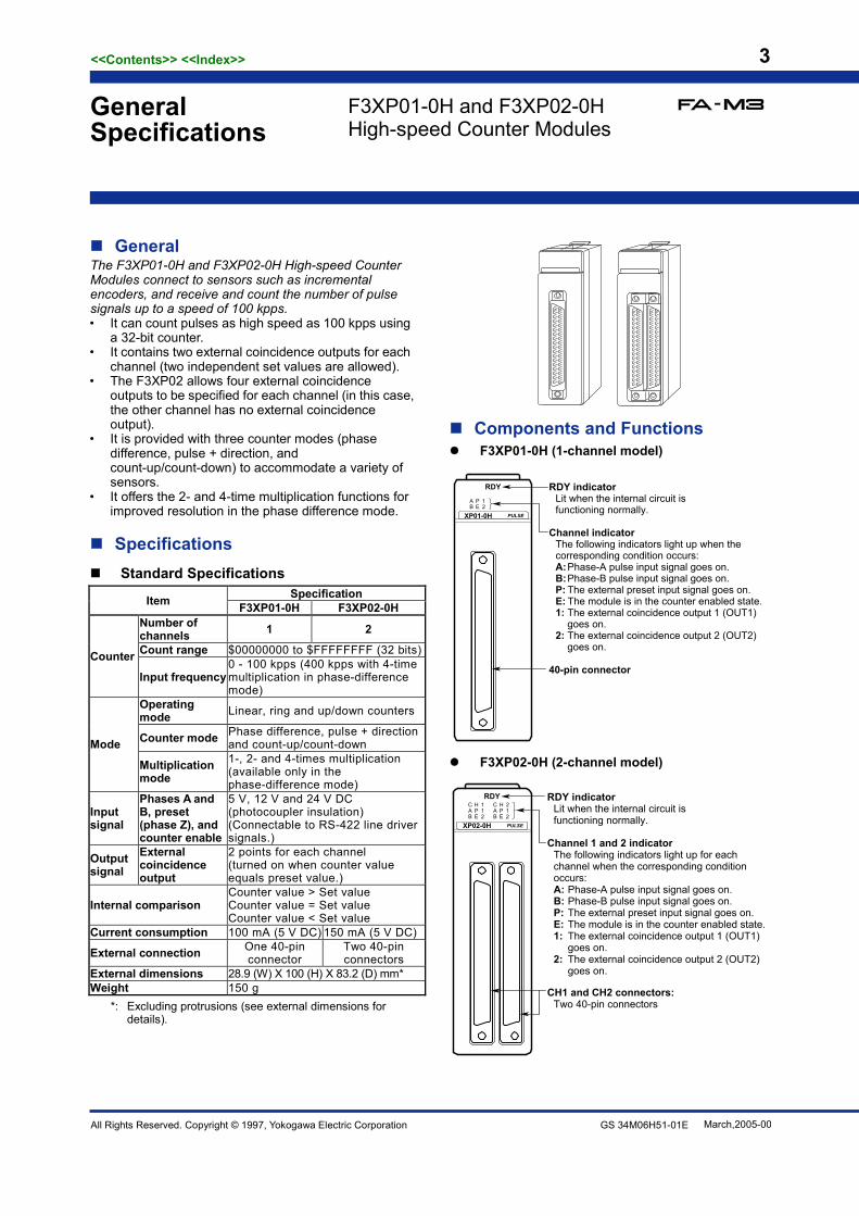
General The F3XP01-0H and F3XP02-0H High-speed Counter Modules connect to sensors such as incremental encoders, and receive and count the number of pulse signals up to a speed of 100 kpps. • It can count pulses as high speed as 100 kpps using
a 32-bit counter. • It contains two external coincidence outputs for each
channel (two independent set values are allowed). • The F3XP02 allows four external coincidence
outputs to be specified for each channel (in this case, the other channel has no external coincidence output).
• It is provided with three counter modes (phase difference, pulse + direction, and count-up/count-down) to accommodate a variety of sensors.
• It offers the 2- and 4-time multiplication functions for improved resolution in the phase difference mode.
Specifications Standard Specifications
Item Specification F3XP01-0H F3XP02-0H
Counter
Number of channels 1 2
Count range $00000000 to $FFFFFFFF (32 bits)
Input frequency 0 - 100 kpps (400 kpps with 4-time multiplication in phase-difference mode)
Mode
Operating mode Linear, ring and up/down counters
Counter mode Phase difference, pulse + direction and count-up/count-down
Multiplication mode
1-, 2- and 4-times multiplication (available only in the phase-difference mode)
Input signal
Phases A and B, preset (phase Z), and counter enable
5 V, 12 V and 24 V DC (photocoupler insulation) (Connectable to RS-422 line driver signals.)
Output signal
External coincidence output
2 points for each channel (turned on when counter value equals preset value.)
Internal comparison Counter value > Set value Counter value = Set value Counter value < Set value
Current consumption 100 mA (5 V DC) 150 mA (5 V DC)
External connection One 40-pin connector
Two 40-pin connectors
External dimensions 28.9 (W) X 100 (H) X 83.2 (D) mm* Weight 150 g
*: Excluding protrusions (see external dimensions for details).
Components and Functions F3XP01-0H (1-channel model)
AB
PE
12
RDY
PULSEXP01-0H
RDY indicatorLit when the internal circuit is functioning normally.
Channel indicatorThe following indicators light up when thecorresponding condition occurs:A: Phase-A pulse input signal goes on.B: Phase-B pulse input signal goes on.P: The external preset input signal goes on.E: The module is in the counter enabled state.1: The external coincidence output 1 (OUT1)
goes on. 2: The external coincidence output 2 (OUT2)
goes on.
40-pin connector
F3XP02-0H (2-channel model)
CAB
HPE
112
CAB
HPE
212
RDY
PULSEXP02-0H
RDY indicatorLit when the internal circuit is functioning normally.
Channel 1 and 2 indicatorThe following indicators light up for each channel when the corresponding condition occurs:A: Phase-A pulse input signal goes on. B: Phase-B pulse input signal goes on.P: The external preset input signal goes on. E: The module is in the counter enabled state.1: The external coincidence output 1 (OUT1)
goes on.2: The external coincidence output 2 (OUT2)
goes on.
CH1 and CH2 connectors:Two 40-pin connectors
General Specifications
F3XP01-0H and F3XP02-0H High-speed Counter Modules
March,2005-00

<<Contents>> <<Index>> 4
All Rights Reserved. Copyright © 2013, Yokogawa Electric Corporation GS 34M06H51-01E
Input/Output Signal Specifications All input/output signals are isolated by photocouplers. External input signals
A : Phase-A pulse input signal B : Phase-B pulse input signal PST : External preset input signal
The preset value is loaded into the counter on the rising edge of the signal.
EN : External counter enable input signal The module performs counting and comparison operations while this signal is on.
External Output Signals OUT1 and OUT2 : External coincidence signals
Electrical Data 1. Input Signals
Signal Ter- minal
Input Type
Rated Input Voltage (Operating Voltage
Range)
Rated Input
Current
Operating Voltage/Current ON OFF
A, B and PST
5 V
DC voltage
5 V DC (4.25 to 5.5 V DC) 16.8 mA 3.5 V min.
10 mA min. 1.5 V max. 2 mA max.
12 V 12 V DC (10.2 to 13.2 V DC) 15.5 mA 8 V min.
10 mA min. 2.4 V max. 2 mA max.
24 V 24 V DC (20.4 to 26.4 V DC) 15.8 mA 16 V min.
10 mA min. 4.8 V max. 2 mA max
EN
5 V 5 V DC (4.25 to 5.5 V DC) 4.6 mA 3.5 V min.
3.2 mA min. 1.5 V max.
0.9 mA max.
12 V 12 V DC (10.2 to 13.2 V DC) 4.6 mA 8 V min.
3.2 mA min. 2.4 V max.
0.9 mA max.
24 V 24 V DC (20.4 to 26.4 V DC) 4.9 mA 16 V min.
3.2 mA min. 4.8 V max.
0.9 mA max.
2. Output Signals
Signal Output Rated Load
Voltage (Maximum
Load Voltage)
Maximum Load
Current
Residual Voltage at ON
Leakage Current at OFF
Surge Protector
Response (Pulse
Input → Output On)
Common Format
OUT1 and
OUT2 Transistor
contact 5 - 24 V DC (26.4 V DC)
0.1 A/point
1.5 V DC max.
0.1 mA max. None 0.1 ms
max. All points
independent.
Configuration Example This example accomplishes high-speed positioning of a motor using two external coincidence outputs of channel 1.
Settings : Set preset values 1 and 2 of channel 1 to the following values: Preset value 1 : Pulse value for the
slow-down command Preset value 2 : Pulse value for the
stop command Operating : When the output relay in a contact output
module (e.g., F3YD32) turns on, the motor is actuated and starts high-speed operation. It starts slowing down when the counter value coincides with preset value 1 and stops when the counter value coincides with preset value 2.
External Connection Diagram CN1 B A
OUT2
OUT1
EN+
PST+
B+
A+
5 V
EN+
PST+
B+
A+
12 V
EN+
PST+
B+
A+
24 V
SHIELD
COM
COM
EN-
PST-
B-
A-
SHIELD
(F3XP02-0H only)2019181716151413121110987654321
2019181716151413121110987654321
EN-
PST-
B-
A-
EN-
PST-
B-
A-
CN2 B AOUT2
OUT1
EN+
PST+
B+
A+
5 V
EN+
PST+
B+
A+
12 V
EN+
PST+
B+
A+
24 V
SHIELD
COM
COM
EN-
PST-
B-
A-
SHIELD
2019181716151413121110987654321
2019181716151413121110987654321
EN-
PST-
B-
A-
EN-
PST-
B-
A-
Applicable External Connectors Connection Method Applicable Connector Remarks
Soldered type Fujitsu:FCN-361J040-AUFCN-360C040-B
connector connector cover
Supplied by the user.
Solderless type Fujitsu:FCN-363J040
FCN-363J-AU FCN-360C040-B
housing contact connector cover
Pressure-welded type Fujitsu:FCN-367J040-AU/FW
Operating Environment There is no restriction on the type of CPU modules that can be used with this module.
Model and Suffix Codes Model Suffix
Code Style Code
Option Code Description
F3XP01 -0H · · · · · · · · · · · · 0-100 Kpps, 1 point, 32 bits F3XP02 -0H · · · · · · · · · · · · 0-100 Kpps, 2 points, 32 bits
Note: See the section on spare parts in the FA-M3 Universalrange Multi-controller (GS 34M6A01-01E) for information on connectors.
External Dimensions
83.2 28.92
100
1.3
Unit: mm
Note: This figure is for the F3XP02-0H.
Jan,2013-00
F3YD32F3XP0¨-0H
FA-M3
High speed
Slow-down
Stop
High-speed counter moduleContact output module, etc.
Encoder Motor
Vel
ocity
Start OUT1 OUT2 Time
Speed controllerStart
OUT1OUT2 Output
Phase A and B

<<Contents>> <<Index>> 5
All Rights Reserved. Copyright © 2014, Yokogawa Electric Corporation GS 34M6H51-01E Mar,2014-00
F3NC32-0N and F3NC34-0N Positioning Module (with pulse output)
General Specification
General The F3NC32-0N and F3NC34-0N positioning modules are advanced
I/O modules to be mounted onto the base module of an FA-M3
range-free controller. It generates a position control path according to
commands from the CPU module and outputs position reference as
pulse trains.
It comes in two models: F3NC32-0N and F3NC34-0N, which can
simultaneously control up to two and four axes respectively. With
position reference pulse output, the module is suitable for driving
servo motors or drivers, as well as stepper motors or drivers in
position control applications.
Features The module has the following features:
Fast and accurate positioning control - High speed position reference pulse output at 5 Mpps max. for
servo motors and 1 Mpps max. for stepper motors provides
comfortable margin for driving linear, DD and other high speed, high
precision motors.
- Short startup time of 0.15 ms for one axis, and 0.5 ms for either four
axes under linear interpolation or two axes under circular
interpolation allows synchronization with high-speed peripheral
devices.
Rich positioning control functions - A full range of positioning control functions enable easy
implementation of any positioning control application. Available
positioning control modes include: position control (PTP, CP and
indexing), speed control, speed control to position control
switchover, and position control to speed control switchover.
Interpolation systems include linear, circular and helical.
- Two operation modes are provided: pattern operation and direct
operation. Pattern operation uses preset action patterns for easier
operation. Direct operation uses a ladder program to set up target
position and specified speed for each positioning action.
Pulse counter and general purpose I/O contacts - A 5-Mpps pulse counter (supporting absolute encoders) is provided
for each axis. As the pulse counter can serve as a motor position
feedback, the module can check the current position, detect position
shift, and by itself implement closed-loop position control for
increased positioning accuracy.
- 6 general inputs and 3 general outputs are provided for each control
axis. When connected to a motor/driver, these I/O contacts can
serve as various control signals: driver alarm, positioning
completed, servo motor on, driver reset, etc.
Parameter setup, action monitoring and action testing using setup tool for positioning modules
- A setup tool known as “ToolBox for Positioning Modules (SF662-ECW)” is
available for easier module configuration and debugging. It can be
used to set up registered parameters, action patterns and position
data, as well as perform action monitoring and testing.
Components and Their Functions F3NC32-0N (with two axis)
RDY
ERR
POSITNC32-0N
RDY indicator: Lit when the internal circuitry is functioning normally
ERR indicator: Lit when an error occurs
Connector for axes 1 and 2 (48P):Connects to external I/O devices such as servo motors and limit switches
F3NC34-0N (with four axes)
RDY
ERR
POSITNC34-0N
RDY indicator: Lit when the internal circuitry is functioning normally
ERR indicator: Lit when an error occurs
Connector for axes 1 and 2 (48P):
Connector for axes 3 and 4 (48P):Connects to external I/O devices such as servo motors and limit switches

<<Contents>> <<Index>> 6
All Rights Reserved. Copyright © 2014, Yokogawa Electric Corporation GS 34M06H51-01E Mar,2014-00
Specifications Item
Specifications F3NC32-0N F3NC34-0N
Control Number of controlled axes 2 4 Control method Open-loop control using position reference pulse output Output pulse type RS-422A compliant differential line driver (AM26C31 or equivalent);
Pulse type selectable for each axis: CW/CCW pulse, travel/direction pulse, and phase A/phase B pulse
Output pulse rates - Using servo motor - Using stepper motor CW/CCW: 5,000,000 (pulse/s) 1,000,000 (pulse/s) Travel/direction: 5,000,000 (pulse/s) 1,000,000 (pulse/s) Phase A/B (x4): 5,000,000 (pulse/s) 1,000,000 (pulse/s) Phase A/B (x2): 2,500,000 (pulse/s) 500,000 (pulse/s) Phase A/B (x1): 1,250,000 (pulse/s) 250,000 (pulse/s)
Counter Number of channels 2 4 Input pulse type - Incremental encoder (phase A/B)
- Absolute encoder (See "Compatible Absolute Encoders" below for details)
Input pulse rate Phase A/B (x 4): 5,000,000 (pulse/s) Phase A/B (x 2): 2,500,000 (pulse/s) Phase A/B (x 1): 1,250,000 (pulse/s)
External contact input 6 inputs per axis (origin input, forward limit input, reverse limit input, driver alarm input, external trigger input, and general input 6); 1 emergency stop input
External contact output 3 outputs per axis (deviation pulse clear signal, general output 2 and general output 3), and 1 SEN signal per axis
Positioning functions
Units of measurement mm, degrees and pulses Control modes Position control (PTP, CP and index);
Speed control, position control to speed control switchover, and speed control to position control switchover
Interpolation modes Single axis movement; 2-axis linear interpolation; 2-axis circular interpolation
Single axis movement; 2-, 3-, and 4-axis linear interpolation; 2-axis circular interpolation, 3- and 4-axis helical interpolation
Operation modes Pattern operation and direct operation Pattern operation PTP movement, CP normal movement, CP pass-by movement, and CP pass-through
movement; Number of action pattern records: 2000 max. (500 actions each for 4 patterns) Number of position data records: 2000 max per axis
Position reference Absolute/incremental position reference -2,147,483,648 to 2,147,483,647 (pulses) -214,748.3648 to 214,748.3647 (mm) -21,474.83648 to 21,474.83647 (degrees)
Speed reference 1 to 5,000,000 (pulses/s) 0.0001 to 214,748.3647 (mm/s) 0.00001 to 21,474.83647 (degree/s)
Acceleration/deceleration curve Automatic trapezoidal acceleration/deceleration (configurable startup speed); Automatic S-shape acceleration/deceleration (startup speed not configurable)
Acceleration/deceleration time 0 to 32,767 (configurable independently for acceleration and deceleration) Others Change in target position during movement
Change in specified speed during movement Origin search Two types of automatic origin search;
Manual origin search (any combination of external contact inputs may be used) Manual operation Jog operation and manual pulse generator mode Other functions Electronic gear, teaching, current position setup;
M code output, override, software limit switch; Counter coincidence or zone coincidence detection
Data backup Flash ROM (100,000 times rewritable) Startup time*1 0.15 ms for single axis positioning
0.16 ms for 2-axis linear interpolation 0.41 ms for 2-axis circular interpolation
0.15 ms for single axis positioning 0.17 ms for 4-axis linear interpolation 0.41 ms for 2-axis circular interpolation
Current consumption (at 5 V DC) 450 mA 540 mA External power supply (24 V DC) 80 mA 120 mA External wiring One 48-pin connector Two 48-pin connectors External dimensions 28.9 (W) x 100 (H) x 83.2 (D) mm*2 Weight 135 g 180g Surrounding air temperature range Operating :0 to 55°C
Storage :-20°C to 75°C Surrounding humidity range Operating :10 to 90% RH (non-condensing)
Storage :10 to 90% RH (non-condensing) Surrounding atmosphere Must be free of corrosive gases, flammable gases or heavy dust.
*1: Up to 1 ms delay may be added if another axis is in motion.
*2: Not including protrusions (see the external dimension diagram for details)

<<Contents>> <<Index>> 7
All Rights Reserved. Copyright © 2014, Yokogawa Electric Corporation GS 34M06H51-01E Mar,2014-00
External Connection Diagram
RDY
ERR
POSITNC32-0N
RDY
ERR
POSITNC34-0N
24b Axis 2 counter phase B input (-) 24a Axis 1 counter phase B input (-) 24b Axis 4 counter phase B input (-) 24a Axis 3 counter phase B input (-) 23b Axis 2 counter phase B input (+) 23a Axis 1 counter phase B input (+) 23b Axis 4 counter phase B input (+) 23a Axis 3 counter phase B input (+) 22b Axis 2 counter phase A input (-) 22a Axis 1 counter phase A input (-) 22b Axis 4 counter phase A input (-) 22a Axis 3 counter phase A input (-) 21b Axis 2 counter phase A input (+) 21a Axis 1 counter phase A input (+) 21b Axis 4 counter phase A input (+) 21a Axis 3 counter phase A input (+) 20b Axis 2 encoder Z-phase input (-) 20a Axis 1 encoder Z-phase input (-) 20b Axis 4 encoder Z-phase input (-) 20a Axis 3 encoder Z-phase input (-) 19b Axis 2 encoder Z-phase input (+) 19a Axis 1 encoder Z-phase input (+) 19b Axis 4 encoder Z-phase input (+) 19a Axis 3 encoder Z-phase input (+) 18b Axis 2 SEN signal output 18a Axis 1 SEN signal output 18b Axis 4 SEN signal output 18a Axis 3 SEN signal output
17b Axis 2 SEN signal output (GND)*1 17a Axis 1 SEN signal output
(GND)*1 17b Axis 4 SEN signal output (GND)*1 17a Axis 3 SEN signal output
(GND)*1 16b Axis 2 general output 3*4 16a Axis 1 general output 3*4 16b Axis 4 general output 3*4 16a Axis 3 general output 3*4 15b Axis 2 general output 2*4 15a Axis 1 general output 2*4 15b Axis 4 general output 2*4 15a Axis 3 general output 2*4
14b Axis 2 deviation pulse clear output *4 14a Axis 1 deviation pulse clear
output *4 14b Axis 4 deviation pulse clear output *4 14a Axis 3 deviation pulse clear
output *4 13b Contact input COM*2 13a Contact input COM*2 13b Contact input COM*2 13a Contact input COM*2 12b Axis 2 general input 6*4 12a Axis 1 general input 6*4 12b Axis 4 general input 6*4 12a Axis 3 general input 6*4 11b Axis 2 external trigger input *4 11a Axis 1 external trigger input *4 11b Axis 4 external trigger input *4 11a Axis 3 external trigger input *4 10b Axis 2 driver alarm input *4 10a Axis 1 driver alarm input *4 10b Axis 4 driver alarm input *4 10a Axis 3 driver alarm input *4 9b Axis 2 reverse limit input *4 9a Axis 1 reverse limit input *4 9b Axis 4 reverse limit input *4 9a Axis 3 reverse limit input *4 8b Axis 2 forward limit input *4 8a Axis 1 forward limit input *4 8b Axis 4 forward limit input *4 8a Axis 3 forward limit input *4 7b Axis 2 origin input *4 7a Axis 1 origin input *4 7b Axis 4 origin input *4 7a Axis 3 origin input *4
6b Axis 2 pulse output B (-) (CCW/direction/phase B) 6a Axis 1 pulse output B (-)
(CCW/direction/phase B) 6b Axis 4 pulse output B (-) (CCW/direction/phase B) 6a Axis 3 pulse output B (-)
(CCW/direction/phase B)
5b Axis 2 pulse output B (+) (CCW/direction/phase B) 5a Axis 1 pulse output B (+)
(CCW/direction/phase B) 5b Axis 4 pulse output B (+) (CCW/direction/phase B) 5a Axis 3 pulse output B (+)
(CCW/direction/phase B)
4b Axis 2 pulse output A (-) (CW/travel/phase A) 4a Axis 1 pulse output A (-)
(CW/travel/phase A) 4b Axis 4 pulse output A (-) (CW/travel/phase A) 4a Axis 3 pulse output A (-)
(CW/travel/phase A)
3b Axis 2 pulse output A (+) (CW/travel/phase A) 3a Axis 1 pulse output A (+)
(CW/travel/phase A) 3b Axis 4 pulse output A (+) (CW/travel/phase A) 3a Axis 3 pulse output A (+)
(CW/travel/phase A) 2b Emergency stop input (GND)*3 2a Emergency stop input *3 2b *5 2a *5
1b 24-V external power supply input (GND)*3 1a 24-V external power supply
input *3 1b 24-V external power supply input (GND)*3 1a 24-V external power supply
input*3
*1: SEN signal output (GND) pins for all axes are connected internally. They may be used as the GND pin for pulse outputs. *2: Contact input COM pins for all axes are connected internally (even across different connectors). *3: The single emergency stop input and 24-V external power supply input are used for all axes. The 24-V external power supply input pins
are connected together internally across different connectors. *4: I/O contacts can be configured as normally-open (NO contact) or normally-closed (NC contact) using registered parameters for each
axis. Origin input, forward limit input, reverse limit input, driver alarm input, and external trigger input may be configured as general inputs,
while deviation pulse clear output may be configured as a general output using registered parameters for each axis. *5: Absolutely do not wire these pins.

<<Contents>> <<Index>> 8
All Rights Reserved. Copyright © 2014, Yokogawa Electric Corporation GS 34M06H51-01E Mar,2014-00
Electrical Characteristics Emergency stop input
Item Specifications Isolation method Photocoupler isolation
Input impedance 7.4 kΩ
Rated input voltage (allowable input voltage range)
24 V DC(20.4 to 26.4 V DC)
Rated input current 3.1 mA
Input voltage/current for emergency stop reset
19.2 V DC min./ 2.4 mA min.
Input voltage/current for emergency stop
5.8 V DC max./ 0.9 mA max.
Pulse output
Item specifications Isolation method Photocoupler isolation
Electrical specification
RS-422A compliant differential line driver (AM26C31 or equivalent)
Transmission rate 5,000,000 pps
Signal Pins
Off (break) On (mark)
Output (+)
Differential positive (high level)
Differential negative (low level)
Output (-)
Differential negative (low level)
Differential positive (high level)
Pulse Output Type Output A Output B
CW/CCW CW signal CCW signal
Travel/direction Travel signal Direction signal
Phase A/phase B Phase A signal Phase B signal
External contact input
Item Specifications
Isolation method Photocoupler isolation
Input impedance 7.4 kΩ
Rated input voltage (allowable input voltage range)
24 V DC(20.4 to 26.4 V DC)
Rated input current 3.1 mA
Voltage/current for on signal (for NO contact)
19.2 V DC min./ 2.4 mA min.
Voltage/current for off signal (for NO contact)
5.8 V DC max./ 0.9 mA max.
Common type Shared common
Response time 2 ms max.
+ -
2b: Emergency stop input (GND)
2a: Emergency stop input
24 V DC
+ -
+ - 13: Contact input COM
12: General input 6
24 V DC
11: External trigger input
(General-purpose input 5)
This internal switch is automatically turned on when the module reads these contact inputs.
10: Driver alarm input
(General-purpose input 4)
9: Reverse limit input
(General-purpose input 3)
8: Forward limit input
(General-purpose input 2)
9: Origin input
(General-purpose input 1)
3: pulse output A (+)
5 V
5 V (GND)
Forward Reverse
CW (output A) ON
OFFCCW (output B)
4: pulse output A (-)
5: pulse output B (+)
6: pulse output B (-)
Forward Reverse
Forward Reverse
Travel (output A)
Direction (output B)
Phase A (output A)
Phase B (output B)
ON
OFF
ON
OFF
<<Contents>> <<Index>> 9
All Rights Reserved. Copyright © 2014, Yokogawa Electric Corporation GS 34M06H51-01E Mar,2014-00
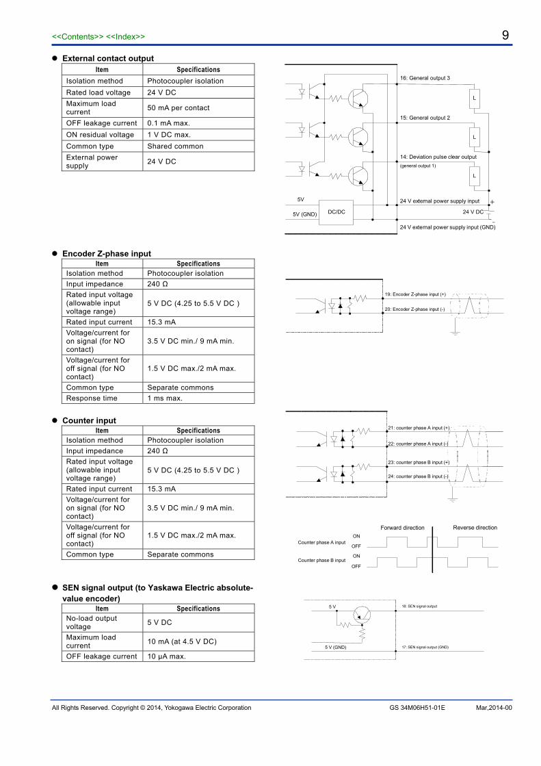
External contact output Item Specifications
Isolation method Photocoupler isolation
Rated load voltage 24 V DC
Maximum load current
50 mA per contact
OFF leakage current 0.1 mA max.
ON residual voltage 1 V DC max.
Common type Shared common
External power supply
24 V DC
Encoder Z-phase input
Item Specifications Isolation method Photocoupler isolation
Input impedance 240 Ω
Rated input voltage (allowable input voltage range)
5 V DC (4.25 to 5.5 V DC)
Rated input current 15.3 mA
Voltage/current for on signal (for NO contact)
3.5 V DC min./ 9 mA min.
Voltage/current for off signal (for NO contact)
1.5 V DC max./2 mA max.
Common type Separate commons
Response time 1 ms max.
Counter input
Item Specifications Isolation method Photocoupler isolation
Input impedance 240 Ω
Rated input voltage (allowable input voltage range)
5 V DC (4.25 to 5.5 V DC)
Rated input current 15.3 mA
Voltage/current for on signal (for NO contact)
3.5 V DC min./ 9 mA min.
Voltage/current for off signal (for NO contact)
1.5 V DC max./2 mA max.
Common type Separate commons
SEN signal output (to Yaskawa Electric absolute-
value encoder) Item Specifications
No-load output voltage
5 V DC
Maximum load current
10 mA (at 4.5 V DC)
OFF leakage current 10 μA max.
-
L
L
L
+
- DC/DC
16: General output 3
5V
5V (GND) 24 V DC
15: General output 2
14: Deviation pulse clear output
(general output 1)
24 V external power supply input
24 V external power supply input (GND)
19: Encoder Z-phase input (+)
20: Encoder Z-phase input (-)
ON
OFF
OFF
ON
Counter phase A input
Forward direction Reverse direction
21: counter phase A input (+)
22: counter phase A input (-)
23: counter phase B input (+)
24: counter phase B input (-)
Counter phase B input
5 V
5 V (GND)
18: SEN signal output
17: SEN signal output (GND)

<<Contents>> <<Index>> 10
All Rights Reserved. Copyright © 2014, Yokogawa Electric Corporation GS 34M6H51-01E Mar,2014-00
Model and Suffix Codes Model Suffix
Code Style Code
Option code Description
F3NC32 -0N – –
2-axis control, 5 Mpps (for driving servo motor)/1 Mpps (for driving stepper motor) pulse rate, 2 counters for input from encoder (including absolute encoder), PTP and CP (linear and circular interpolation), direct and pattern operation
F3NC34 -0N – –
4-axis control, 5 Mpps (for driving servo motor)/1 Mpps (for driving stepper motor) pulse rate, 4 counters for input from encoder (including absolute encoder), PTP and CP (linear, circular, and helical interpolation), direct and pattern operation
Operating Environment This module can be used with the following CPU modules:
CPU Module ROM Revision F3SP28-3N,F3SP38-6N
F3SP53-4H,F3SP58-6H Rev.7 or later
Other CPUs Any
Compatible Absolute Encoders Absolute encoders from Yaskawa Electric or equivalent:
- Yaskawa Electric's Σ-III and Σ-II series for AC servo motor drive Absolute encoders (1 Mbps, Manchester coding) from Sanyo Electric or equivalent:
- Sanyo Electric's ABS-E and ABS-RII absolute sensors (containing RA062M) for use with the Q-series and P-series AC servo-systems
Compatible External Interface Connectors Connection Compatible Connector Remarks
Soldered FCN-361J048-AU connector, and FCN-360C048-B connector cover from Fujitsu Limited
To be purchased separately. Crimp-on
FCN-363J048 housing, FCN-363J-AU contacts, and FCN-360C048-B connector cover from Fujitsu Limited
Pressure-welded FCN-367J048-AU/F from Fujitsu Limited
External Dimensions
83.2 28.9 2
1.3
100
Unit: mm
<<Contents>> <<Index>> 11
All Rights Reserved. Copyright © 2014, Yokogawa Electric Corporation GS 34M6H51-01E Mar,2014-00
Function Overview
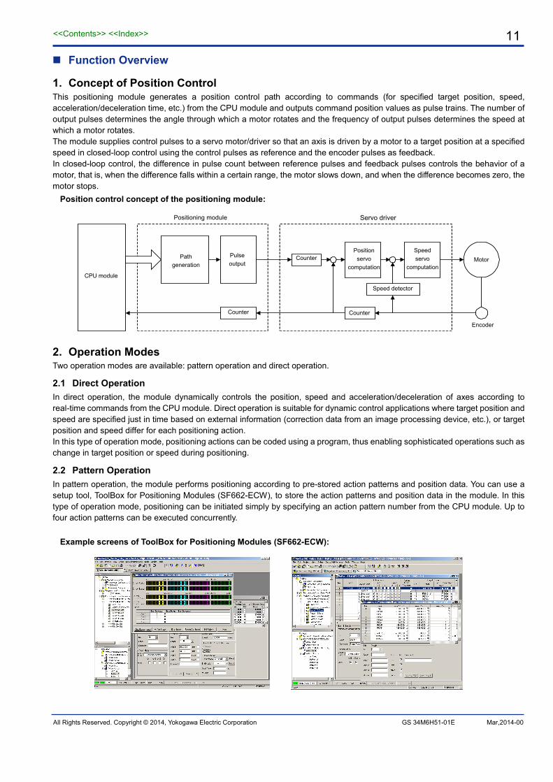
1. Concept of Position Control This positioning module generates a position control path according to commands (for specified target position, speed, acceleration/deceleration time, etc.) from the CPU module and outputs command position values as pulse trains. The number of output pulses determines the angle through which a motor rotates and the frequency of output pulses determines the speed at which a motor rotates. The module supplies control pulses to a servo motor/driver so that an axis is driven by a motor to a target position at a specified speed in closed-loop control using the control pulses as reference and the encoder pulses as feedback. In closed-loop control, the difference in pulse count between reference pulses and feedback pulses controls the behavior of a motor, that is, when the difference falls within a certain range, the motor slows down, and when the difference becomes zero, the motor stops.
Position control concept of the positioning module:
Motor
Encoder
Positioning module Servo driver
Counter
Position servo
computation
Speed servo
computation CPU module
Pulse output
Path generation
Counter
Speed detector
Counter
2. Operation Modes Two operation modes are available: pattern operation and direct operation.
2.1 Direct Operation In direct operation, the module dynamically controls the position, speed and acceleration/deceleration of axes according to real-time commands from the CPU module. Direct operation is suitable for dynamic control applications where target position and speed are specified just in time based on external information (correction data from an image processing device, etc.), or target position and speed differ for each positioning action. In this type of operation mode, positioning actions can be coded using a program, thus enabling sophisticated operations such as change in target position or speed during positioning.
2.2 Pattern Operation In pattern operation, the module performs positioning according to pre-stored action patterns and position data. You can use a setup tool, ToolBox for Positioning Modules (SF662-ECW), to store the action patterns and position data in the module. In this type of operation mode, positioning can be initiated simply by specifying an action pattern number from the CPU module. Up to four action patterns can be executed concurrently.
Example screens of ToolBox for Positioning Modules (SF662-ECW):
<<Contents>> <<Index>> 12
All Rights Reserved. Copyright © 2014, Yokogawa Electric Corporation GS 34M6H51-01E Mar,2014-00
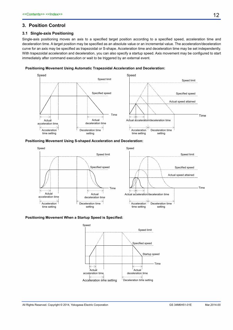
3. Position Control 3.1 Single-axis Positioning Single-axis positioning moves an axis to a specified target position according to a specified speed, acceleration time and deceleration time. A target position may be specified as an absolute value or an incremental value. The acceleration/deceleration curve for an axis may be specified as trapezoidal or S-shape. Acceleration time and deceleration time may be set independently. With trapezoidal acceleration and deceleration, you can also specify a startup speed. Axis movement may be configured to start immediately after command execution or wait to be triggered by an external event.
Positioning Movement Using Automatic Trapezoidal Acceleration and Deceleration:
Time
Speed
Specified speed
Speed limit
Actual acceleration/deceleration time
Actual speed attained
Speed
Time
Speed limit
Actual acceleration time
Actual deceleration time
Acceleration time setting
Deceleration time setting
Specified speed
Acceleration time setting
Deceleration time setting
Positioning Movement Using S-shaped Acceleration and Deceleration:
Time
Specified speed
Actual acceleration time
Actual deceleration time
Acceleration time setting
Deceleration time setting
Speed
Speed limit
Specified speed
Actual speed attained
Time
Actual acceleration/deceleration time
Acceleration time setting
Deceleration time setting
Speed
Speed limit
Positioning Movement When a Startup Speed is Specified:
Speed
Speed limit
Time
Specified speed
Acceleration time setting Deceleration time setting
Actual acceleration time
Actual deceleration time
Startup speed

<<Contents>> <<Index>> 13
All Rights Reserved. Copyright © 2014, Yokogawa Electric Corporation GS 34M6H51-01E Mar,2014-00
3.2 Interpolated Positioning Interpolated positioning moves multiple axes in tandem to reach a target position by following a path obtained using interpolation. The module supports 2-, 3-, and 4-axis linear interpolation, 2-axis circular interpolation, as well as 3- and 4-axis helical interpolation. A target position may be specified as an absolute value or an incremental value. Specified speed may be a combined speed or axis speed. Combined speed in 2-axis circular or helical interpolation is measured along the tangential line of the circular or helical path. The acceleration/deceleration curve for an axis may be specified as trapezoidal or S-shaped. Acceleration time and deceleration time may be set independently. Axis movement may be configured to start immediately after command execution or wait to be triggered by an external event.
2-axis linear interpolation: 3-axis linear interpolation:
Y axis
X-axis travel
Y-ax
is tr
avel
X axis
Z axis
X-axis travel
Y axis
Y-axis travel
Z-ax
is tr
avel
Circular interpolation (using sub point):
Circular interpolation (CW using center):
Circular interpolation (CCW using center):
Y axis Current position
Target position
Sub point
Combined (tangential) speed
Center point
Y axis Current position
Target position
Combined (tangential) speed
X axis
Center point
Target position Y axis
X axis
Current position
Combined (tangential) speed
X axis
Helical interpolation (CW using center): Helical interpolation (CCW using center):
Y axis
Z axis
X axis Center point
Start point
Target point
Combined (tangential) speed
Z axis
X axis Start point
Center point
Target point
Combined (tangential) speed
Y axis

<<Contents>> <<Index>> 14
All Rights Reserved. Copyright © 2014, Yokogawa Electric Corporation GS 34M6H51-01E Mar,2014-00
3.3 Pass-by and Pass-through Movement In pattern operation, two successive positioning actions may be combined so that axes do not stop between actions but moves continuously, passing by or passing through the first target position. Compared to ordinary CP movement, pass-by and pass-through CP movements take shorter time, and are thus effective for collision prevention or tack time reduction. The actions to be combined may be in different directions. In direct operation, pass-by movement can be implemented by changing the specified speed during movement.
Path and Speed for Ordinary CP Movement:
X axis
Y axis X axis speed
Time
P0
P1
P2 Time
Y axis speed
Path and Speed for Pass-by CP Movement:
P0
P1
P2
X axis
Y axis X axis speed
Time
Time
Y axis speed
Transition interval
Path and Speed for Pass-through CP Movement:
P0
P1
P2
X axis
Y axis X axis speed
Y axis speed
Time
Time

<<Contents>> <<Index>> 15
All Rights Reserved. Copyright © 2014, Yokogawa Electric Corporation GS 34M6H51-01E Mar,2014-00
3.4 Changing Target Position during Positioning In direct operation, the target position, as well as the specified speed, may be changed during positioning. The change in target position can be in a different direction.
Path and Speed when Target Position is Changed during Positioning:
P0
P1'
P2
P1
X axis
Y axis
Time
X axis speed Transition
Y axis speed
Time
3.5 Changing Specified Speed during Positioning In direct operation, the movement speed may be changed during positioning.
Changing speed during positioning:
↑ ↑
Speed
Time
Speed change request Speed change request
3.6 Index Control In index control, current and target positions are handled as ring data that assumes values from zero to a specified index range (0-360ºin the example shown below). A target position may be specified as an absolute value or an incremental value. If an absolute target position is specified, an axis rotates in either CW or CCW direction to reach the target position taking the shorter path (shortest path control). When specifying an increment target position, an axis can be made to rotate beyond one revolution. Index positioning can also be initiated during index speed control movement of an axis started with only a specified speed to move the axis to a specified target position.
Index Control (Shortest Path Control):
360° 0°
90°
330°
360°
Start position
Current position

<<Contents>> <<Index>> 16
All Rights Reserved. Copyright © 2014, Yokogawa Electric Corporation GS 34M6H51-01E Mar,2014-00
4. Speed Control
4.1 Speed Control Movement
Speed control moves an axis in the same direction according to a specified speed, acceleration time or deceleration time. The acceleration/deceleration curve for an axis may be specified as trapezoidal or S-shape. Acceleration time and deceleration time may be set independently. Axis movement may be configured to start immediately after command execution or be triggered by an external event.
Speed Change in Speed Control:
↑ ↑ ↑ ↑ Time
Speed
Speed change requestSpeed change request Decelerate & stop request Speed change request
4.2 Speed Control to Position Control Switchover
During speed control movement, axes can be switched from speed control mode to position control mode to be moved to a new target position, which may be specified as an absolute value or an incremental value. You can choose to reset the current position to zero at the time of control switchover or continue with the current position values. The acceleration/deceleration curve of an axis may be specified as trapezoidal or S-shape. Acceleration time and deceleration time may be set independently. Control switchover may be configured to take place immediately after command execution, or be triggered by an external event, such as external trigger input, external trigger input and Z-phase input, counter coincidence detection, or zone coincidence detection. When the Encoder Z-phase input is used as a trigger, you can specify the Z-phase edge and the number of Z-phase detections.
Speed Control to Position Control Switchover:
- When Z-phase Input is Not Used
↑
Time
Speed
Target position (travel)
Control switchover request
Speed control Position control
- When Z-phase Input is Used (Z-phase rising edge is to be detected twice)
↑
Speed
Target position (travel)
Control switchover request
Speed control
Time
Position control
Z phase

<<Contents>> <<Index>> 17
All Rights Reserved. Copyright © 2014, Yokogawa Electric Corporation GS 34M6H51-01E Mar,2014-00
5. Origin Search There are two ways to perform origin search: automatic and manual. In automatic origin search, the origin search behavior is defined by the module's registered parameters. In manual origin search, the origin search behavior is arbitrarily defined by an application program.
5.1 Automatic Origin Search
In automatic origin search, the module searches for the origin automatically using the external switches according to the registered parameters values, and then enters Z-phase search. The search may be configured to use or to not use the origin switch, in addition to using the forward and reverse limit switches. In Z-phase search, the module counts a specified number of Z-phase pulses, and then stops the axis immediately. The stop position is taken as the origin. An origin offset may be specified if required. The module then outputs a deviation pulse clear signal for a specified duration.
Automatic origin search (mode 0: using origin switch):
Reverse limit switch Origin switch
Z-phase pulse
Forward limit switch
Search speed 1
Startup speed
Search speed 2
Automatic origin search (mode 1: not using origin switch):
Reverse limit switch
Z-phase pulse
Forward limit switch
Search speed 1
Startup speed
Search speed 2
5.2 Manual Origin Search
In manual origin search, the origin search behavior is arbitrarily defined by an application program which writes the origin search specified speed, origin search direction, origin search mode (defines the desired action when an external contact input is detected), Z-phase edge selection, and other origin search related parameters before initiating origin search. The module searches for the origin according to the parameter values as it detects changes in external contact inputs. When the required change is detected, it either stops or shifts to Z-phase search. If origin search must be done at different speeds or in different directions depending on the states of the external contact inputs, it may be divided into two or more origin search operations using different sets of parameters.
Manual origin search:
For a rise in contact input
When "ignore' is specified
When "shift to Z-phase search" is specified
When "decelerate and stop"is specified
When "stop immediately" isspecified
Stop when Z-phase is detected
<<Contents>> <<Index>> 18
All Rights Reserved. Copyright © 2014, Yokogawa Electric Corporation GS 34M6H51-01E Mar,2014-00
FA-M3
Positioning pulse
Positioning module
Encoder feedback pulse
6. Counter Function
6.1 Manual Pulse Generator (MPG) Mode
You can manually operate a motor for testing or other purposes by connecting a manual pulse generator to any of the counter inputs (2 channels for F3NC32-0N and 4 channels for F3NC34-0N). The relationship between the pulse count from a manual pulse generator and the travel of an axis depends on the multiplication and decimal point position specified for manual pulse generator mode. As the manual pulse generator mode is configured independently for each axis, you can manually control two axes at the same time using two manual pulse generators, or multiple axes using a single manual pulse generator.
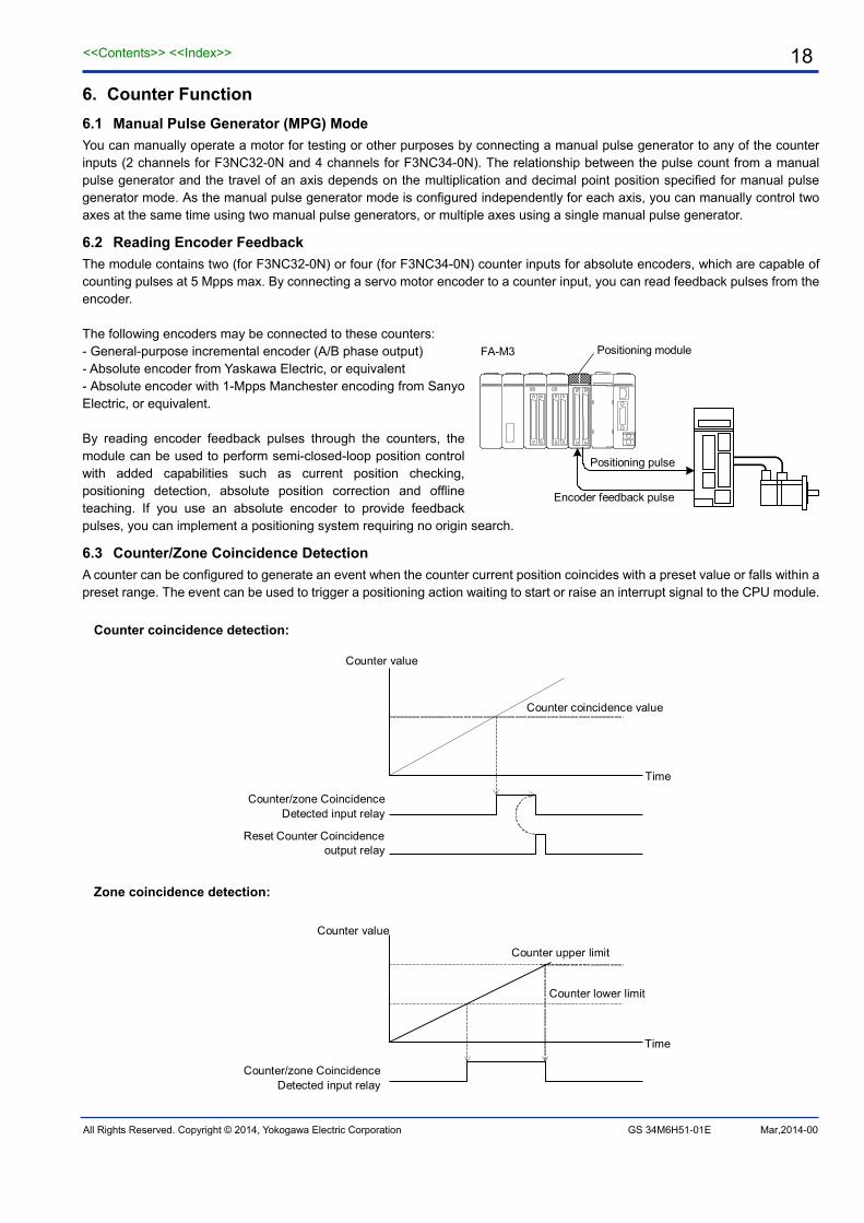
6.2 Reading Encoder Feedback
The module contains two (for F3NC32-0N) or four (for F3NC34-0N) counter inputs for absolute encoders, which are capable of counting pulses at 5 Mpps max. By connecting a servo motor encoder to a counter input, you can read feedback pulses from the encoder. The following encoders may be connected to these counters: - General-purpose incremental encoder (A/B phase output) - Absolute encoder from Yaskawa Electric, or equivalent - Absolute encoder with 1-Mpps Manchester encoding from Sanyo Electric, or equivalent. By reading encoder feedback pulses through the counters, the module can be used to perform semi-closed-loop position control with added capabilities such as current position checking, positioning detection, absolute position correction and offline teaching. If you use an absolute encoder to provide feedback pulses, you can implement a positioning system requiring no origin search.
6.3 Counter/Zone Coincidence Detection
A counter can be configured to generate an event when the counter current position coincides with a preset value or falls within a preset range. The event can be used to trigger a positioning action waiting to start or raise an interrupt signal to the CPU module.
Counter coincidence detection:
Counter value
Counter/zone CoincidenceDetected input relay
Time
Counter coincidence value
Reset Counter Coincidenceoutput relay
Zone coincidence detection:
Time
Counter value
Counter upper limit
Counter lower limit
Counter/zone CoincidenceDetected input relay
<<Contents>> <<Index>> 19
All Rights Reserved. Copyright © 2014, Yokogawa Electric Corporation GS 34M6H51-01E Mar,2014-00
7. Other functions
7.1 External I/O Contacts
The module has one emergency stop input contact as well as six input contacts, three output contacts, and one SEN signal output contact for each axis. All I/O contacts can be individually configured as normally-open (NO) or normally-closed (NC) contact using axis registered parameters. I/O contacts that are allocated for specific functions by default can be reconfigured as general I/O contacts. By connecting external equipment to the general I/O contacts, the CPU module can monitor the equipment by reading the input contacts, as well as control the equipment by turning on or turning off the output contacts.
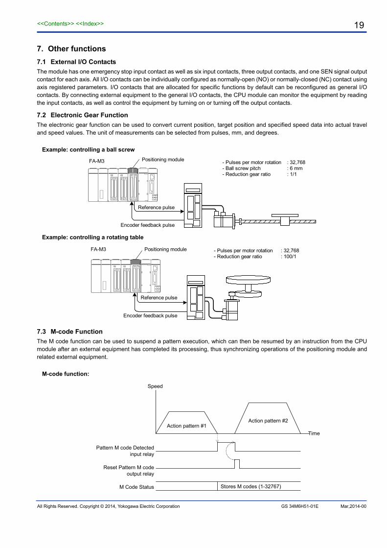
7.2 Electronic Gear Function
The electronic gear function can be used to convert current position, target position and specified speed data into actual travel and speed values. The unit of measurements can be selected from pulses, mm, and degrees.
Example: controlling a ball screw
FA-M3 Positioning module
Reference pulse
Encoder feedback pulse
- Pulses per motor rotation : 32,768 - Ball screw pitch : 6 mm - Reduction gear ratio : 1/1
Example: controlling a rotating table
FA-M3
Reference pulse
Encoder feedback pulse
- Pulses per motor rotation : 32,768 - Reduction gear ratio : 100/1
Positioning module
7.3 M-code Function
The M code function can be used to suspend a pattern execution, which can then be resumed by an instruction from the CPU module after an external equipment has completed its processing, thus synchronizing operations of the positioning module and related external equipment.
M-code function:
Speed
Time Action pattern #1
Action pattern #2
Stores M codes (1-32767)
Pattern M code Detectedinput relay
Reset Pattern M codeoutput relay
M Code Status

<<Contents>> <<Index>> 20
All Rights Reserved. Copyright © 2014, Yokogawa Electric Corporation GS 34M6H51-01E Mar,2014-00
7.4 Teach Function The Teach function provides a convenient way to store current position data, counter current position data and entered numerical data into the position data table as you manually move an axis using the jog function or manual pulse generator mode. The teach function allows storing of absolute or incremental position data, as well as concurrent saving of data for two or more axes.
7.5 Override Function You can override the specified speed during positioning by scaling it to 1 and 500% of its original speed. In direct operation, the module executes a speed change immediately after the override value is changed. In pattern operation, the new override value is not applied to the current action of an executing pattern but to subsequent pattern actions.
7.6 Set Current Position You can change the current position value and/or the counter current position of an axis in Positioning Completed state. You can also set the current position and the counter current position to the same value.
7.7 Saving Parameters to the Module You can save parameters including axis registered parameters, pattern registered parameters, action pattern table, and position data table in the flash memory of the module. At power up or system reset, the contents of the flash memory are automatically restored to these parameters.
Setting and saving parameters:
CPU module
CPU interface
Write parameters
Read parameters
Work area
Flash memory
Execute Set Parameters command
Execute Save to Flash Memory
command
At power up or system reset
Positioning module
<<Contents>> <<Index>> 21
All Rights Reserved. Copyright © 2014, Yokogawa Electric Corporation GS 34M06H51-01E Mar,2014-00
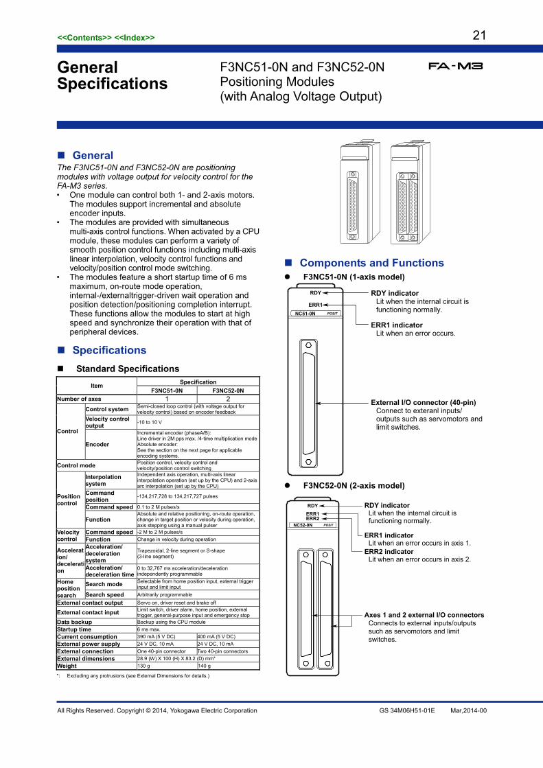
General The F3NC51-0N and F3NC52-0N are positioning modules with voltage output for velocity control for the FA-M3 series. • One module can control both 1- and 2-axis motors.
The modules support incremental and absolute encoder inputs.
• The modules are provided with simultaneous multi-axis control functions. When activated by a CPU module, these modules can perform a variety of smooth position control functions including multi-axis linear interpolation, velocity control functions and velocity/position control mode switching.
• The modules feature a short startup time of 6 ms maximum, on-route mode operation, internal-/externaltrigger-driven wait operation and position detection/positioning completion interrupt. These functions allow the modules to start at high speed and synchronize their operation with that of peripheral devices.
Specifications Standard Specifications
Item Specification F3NC51-0N F3NC52-0N
Number of axes 1 2
Control
Control system Semi-closed loop control (with voltage output for velocity control) based on encoder feedback
Velocity control output -10 to 10 V
Encoder
Incremental encoder (phaseA/B): Line driver in 2M pps max. /4-time multiplication mode Absolute encoder: See the section on the next page for applicable encoding systems.
Control mode Position control, velocity control and velocity/position control switching
Position control
Interpolation system
Independent axis operation, multi-axis linear interpolation operation (set up by the CPU) and 2-axis arc interpolation (set up by the CPU)
Command position -134,217,728 to 134,217,727 pulses
Command speed 0.1 to 2 M pulses/s
Function Absolute and relative positioning, on-route operation, change in target position or velocity during operation, axis stepping using a manual pulser
Velocity control
Command speed -2 M to 2 M pulses/s Function Change in velocity during operation
Acceleration/ deceleration
Acceleration/ deceleration system
Trapezoidal, 2-line segment or S-shape (3-line segment)
Acceleration/ deceleration time
0 to 32,767 ms acceleration/deceleration independently programmable
Home position search
Search mode Selectable from home position input, external trigger input and limit input
Search speed Arbitrarily programmable
External contact output Servo on, driver reset and brake off
External contact input Limit switch, driver alarm, home position, external trigger, general-purpose input and emergency stop
Data backup Backup using the CPU module Startup time 6 ms max. Current consumption 390 mA (5 V DC) 400 mA (5 V DC) External power supply 24 V DC, 10 mA 24 V DC, 10 mA External connection One 40-pin connector Two 40-pin connectors External dimensions 28.9 (W) X 100 (H) X 83.2 (D) mm* Weight 130 g 140 g
*: Excluding any protrusions (see External Dimensions for details.)
Components and Functions F3NC51-0N (1-axis model)
RDY indicatorLit when the internal circuit is functioning normally.
ERR1 indicatorLit when an error occurs.
External I/O connector (40-pin)Connect to exteranl inputs/outputs such as servomotors and limit switches.
RDY
ERR1POSITNC51-0N
F3NC52-0N (2-axis model)
RDYERR1ERR2
POSIT
RDY indicatorLit when the internal circuit is functioning normally.
ERR1 indicatorLit when an error occurs in axis 1.
Axes 1 and 2 external I/O connectorsConnects to external inputs/outputs such as servomotors and limit switches.
ERR2 indicatorLit when an error occurs in axis 2.
NC52-0N
General Specifications
F3NC51-0N and F3NC52-0N Positioning Modules (with Analog Voltage Output)

<<Contents>> <<Index>> 22
All Rights Reserved. Copyright © 2014, Yokogawa Electric Corporation GS 34M06H51-01E Mar,2014-00
External Connection Diagram Pin No. Signal Name Electrical Specification
20b Emergency stop input*1 24 V DC, 4.1 mA 20a Emergency stop input*1 19b External contact input 6*2 24 V DC, 4.1 mA 19a External contact input 5 (external trigger) *2 24 V DC, 4.1 mA 18b External contact input 4 (home position) *2 24 V DC, 4.1 mA 18a External contact input 3 (driver alarm) *2 24 V DC, 4.1 mA 17b External contact input 2 (negative direction limit) *2 24 V DC, 4.1 mA 17a External contact input 1 (positive direction limit) *2 24 V DC, 4.1 mA 16b External contact input (COM) 16a 15b Voltage output for velocity control -10 to 10 V DC, 5 mA 15a Voltage output for velocity control (GND) 14b Shield (FG) 14a Shield (FG) 13b Encoder Z-phse input Z RS-422A compliant differential
signal, terminated by 220 Ω 13a Encoder Z-phse input *Z 12b Encoder B-phse input B RS-422A compliant differential
signal, terminated by 220 Ω 12a Encoder B-phse input *B 11b Encoder A-phse input A RS-422A compliant differential
signal, terminated by 220 Ω 11a Encoder A-phse input *A 10b Encoder/manual pulser signal ground 10a Encoder/manual pulser signal ground 9b SEN (For Yaskawa Electric absolute encoder) 5 V DC, 10 mA 9a SEN_0V(GND) 8b Reserved 8a Reserved 7b Manual pulser input B-phase B*3 RS-422A compliant differential
signal, terminated by 220 Ω 7a Manual pulser input B-phase *B*3 6b Manual pulser input A-phase A*3 RS-422A compliant differential
signal, terminated by 220 Ω 6a Manual pulser input A-phase *A*3 5b 5a 4b 4a External contact output (closed OFF) 24 V DC, 0.1 A 3b External contact output (driver reset) 24 V DC, 0.1 A 3a External contact output (servo ON) 24 V DC, 0.1 A 2b External contact output (COM) 2a External contact output (24 V) 1b External contact output (0 V-in) 1a External contact output (24 V-in)
*1: The emergency stop input is only for axis-1 connector. This pin in axis-2 connector is not connected internally. The signal from axis-1 connector is shared by two connectors.
*2: External contact inputs (1-6) can be programmed for general-purpose inputs.
*3: The manual pulser input is only for axis-1 connector. This pin in axis-2 connector is not connected internally. The signal from axis-1 connector is shared by two connectors.
Applicable External Connectors Connection Method Applicable Connector Remarks
Soldered type Fujitsu:FCN-361J040-AUFCN-360C040-B
connector connector cover
Supplied by the user. Solderless type
Fujitsu:FCN-363J040 FCN-363J-AU FCN-360C040-B
housing contact connector cover
Pressure-welded type Fujitsu:FCN-367J040-AU/FW
Operating Environment There is no restriction on the type of CPU modules that can be used with this module.
Applicable Absolute Encoders • Yaskawa Electric serial absolute encoder (Yaskawa
S series) • Sanyo Electric serial absolute encoders and compatibles
(Manchester coded serial transmission system, Sanyo Electric P series, and Matsushita Electric MINAS series)
Model and Suffix Codes Model Suffix
Code Style Code
Option Code Description
F3NC51 -0N ·········· ·········· 1-axis, position loop control, -10 V to 10 V output for velocity control, 2 Mpps maximum velocity
F3NC52 -0N ·········· ·········· 2-axis, position loop control, -10 V to 10 V output for velocity control, 2 Mpps maximum velocity
Note: See the section on spare parts in the FA-M3 Range-free Multi-controller (GS 34M6A01-01E) for information on connectors.
External Dimensions
83.2 28.92
100
1.3
Unit: mm
Note: This figure is for the F3NC52-0N.

<<Contents>> <<Index>> 23
All Rights Reserved. Copyright © 2014, Yokogawa Electric Corporation GS 34M06H51-01E Mar,2014-00
Function Overview 1. Positioning System This is a positioning module with voltage output for velocity control for the FA-M3 series. It generates positioning trajectory data, performs position-loop computations based on the feedback signal from an external position detector (incremental encoder or absolute encoder), and generates velocity command values in the form of an analog voltage, according to commands from a CPU module.
CPU moduleTrajectorygeneration
Positioning module Servo driver
-1010V-10 -10V
Motor
Encoder
Position servocomputation(14 bit D/A)
Counter(28 bits)
Velocity servoservo
computation
Velocitydetector
+
-
+
-
2. Position Control 2.1 Positioning Operation A positioning operation is started by writing the velocity setpoint (pulses/ms), target position (pulses), acceleration time (ms), and deceleration time (ms) from the CPU module and turning on the operation start relay. The positioning completion relay turns on when the output of position command pulses ends. • The user can specify, as the target position, an absolute, relative position (with reference to the encoder position) or
a relative position (with reference to the preceding target position). • The acceleration/deceleration curve forms a trapezoid, 2-line segment, or S-shape (3-line segment). The
acceleration and deceleration time must be set separately. • A positioning range (pulses) and positioning timeout value (ms) must be specified to identify the end of positioning. • The user can set up the positioning module so that positioning can be started up in normal operation as well as with
remote/local triggering features. Velocity and Acceleration/Deceleration Times in the Trapezoidal Drive/Triangular Drive Mode
VelocityVelocity setpoint
Acceleration time Deceleration time
Time
Operating distance
VelocityVelocity setpoint
Actual velocity attained
Deceleration timeActual acceleration/deceleration times
TimeAcceleration time
Operating distance
End-of-positioning timing
Position Positioning timeout time
End-of-positioning determined
Set value reachedPositioning
range
Current value
Time
Prespecifiedvalue

<<Contents>> <<Index>> 24
All Rights Reserved. Copyright © 2014, Yokogawa Electric Corporation GS 34M06H51-01E Mar,2014-00
2.2 Multi-axis Linear Interpolation Operation A linear interpolation operation is started by writing the velocity setpoint (pulses/ms), target position (pulses), acceleration time (ms) and deceleration time (ms) from the CPU module and turning on the operation start relays for all axes at the same time. When the output of position command pulses for an axis ends, the positioning completion relay associated with that axis turns on. The acceleration time (ms), deceleration time (ms) and acceleration/deceleration pattern must be set to the same values for all axes that are subject to linear interpolation processing. The velocity setpoint (pulses/ms) for the axes must be calculated and preset so that it is equal to the ratio of the distances traveled along the axes. Multi-axis Linear Interpolation Operation (2-axis)
Velocity Velocity setpoint for-X axis
Velocity setpoint for-Y axis
Acceleration time Deceleration time
Time
Distance traveledalong X-axis
Distance traveledalong Y-axis
Y-axis
Distance traveled along X-axis
Dis
tanc
e tr
avel
ed a
long
Y-a
xis
X-axis
2.3 On-route Operation When the next positioning operation is started while the execution of the current positioning operation is in progress, the positioning module keeps on combining the two positioning operations until the preceding positioning operation ends. This mode of operation is called an on-route operation and the interval during which the two positioning operations overlap is called an on-route interval. The on-route operation allows the positioning module to continue its operation toward the next target position without stopping at the preceding target position. • The direction of movement may be changed during an on-route operation. Normal Positioning Operation and On-route Operation Normal Positioning Operation
X-axis velocity
TimeStart Start
On-route Operation Example of an On-route Operation Using 2-axis Linear Interpolation
X-axis velocity On-route interval On-route interval
TimeStart Start Start
Y-axis
X-axis

<<Contents>> <<Index>> 25
All Rights Reserved. Copyright © 2014, Yokogawa Electric Corporation GS 34M06H51-01E Mar,2014-00
2.4 Changing the Target Position during Positioning The positioning module changes the target position when the user turns on a relay to change the target position by writing new positioning parameters during positioning operation. The user can also change the target position in such a way that the direction of movement is also changed (in this case, the positioning module decelerates and stops promptly and starts positioning to the new target position.)
Target Position Change Operation When Direction Change Is Not Involved
When a Direction Change Is Involved
Velocity
TimeStart
Request to change target position
Velocity
TimeStart
Request to change target position 2.5 Changing the Velocity during Positioning The positioning module changes the traveling velocity when the user turns on a relay to change the velocity by writing a new velocity (pulses/ms) during the positioning operation. Change Velocity Operation
Velocity
TimeStart
Request to change target position
Request to change target position
3. Velocity Control A velocity control operation is executed by writing the velocity setpoint (pulses/ms, specify a negative value to drive the target in a negative direction), acceleration time (ms) and deceleration time (ms) from the CPU module and turning on the operation startup relay. • The velocity can be changed while the positioning module is running. • The acceleration/deceleration curve forms a trapezoid, 2-line segment or S-shape (3-line segment). The
acceleration and deceleration times must be set separately. • A positioning range (pulses) and positioning timeout value (ms) must be specified to identify the end of positioning. • The user can set up the positioning module so that positioning can be started up in normal operaion as well as with
remote/local triggering features. Velocity Control and Change Operations
Velocity
TimeStartRequest to change velocity Request to change velocity Request to change velocity Deceleration and stop request

<<Contents>> <<Index>> 26
All Rights Reserved. Copyright © 2014, Yokogawa Electric Corporation GS 34M06H51-01E Mar,2014-00
4. Velocity/Position Control Switching Control 4.1 Velocity/Position Control Switching The module starts positioning operation from scratch if the velocity setpoint (pulses/ms), target position (pulses), acceleration time (ms) and deceleration time (ms) are written from the CPU module, and then the control mode is changed to position control. • The acceleration/deceleration curve forms a trapezoid, 2-line segment or S-shape (3-line segment). The
acceleration and deceleration times must be set separately. • A positioning range (pulses) and positioning timeout value (ms) must be specified to identify the end of positioning. • The user can switch from velocity to position control mode in normal transfer operation as well as with remote
triggering features. • The user can set edges and counts when the Z-phase count is selected. Velocity to Position Control Switching Operation No Z-phase Count is Specified
Time
Velocity
StartRequest to change control mode to position control
Target position(distance traveled)
A Z-phase Count is Specified (Rising Edge, 2 Times)
Velocity
Start
Z-phase
Request to change control mode toposition control
Target position(distance traveled)
4.2 Position to Velocity Control Switching When the control mode is switched from position to velocity control during positioning operation, the positioning module performs velocity control operation while maintaining the velocity that was set before the control mode switching occurs.
5. Acceleration / Deceleration The legitimate position/velocity control acceleration/deceleration modes are trapezoid, 2-line segment and S-shape (3-line segment). The user can specify the mode and time separately for both acceleration and deceleration. Neither 2-line segment nor S-shape is formed, however, when the target setpoint or velocity is changed during the positioning operation. Acceleration/Deceleration Methods in Position and Velocity Control Operation Trapezoid 2-line Segment S-shape (3-line segment)
Velocity
Time
Velocity
Time
Velocity
Time
<<Contents>> <<Index>> 27
All Rights Reserved. Copyright © 2014, Yokogawa Electric Corporation GS 34M06H51-01E Mar,2014-00
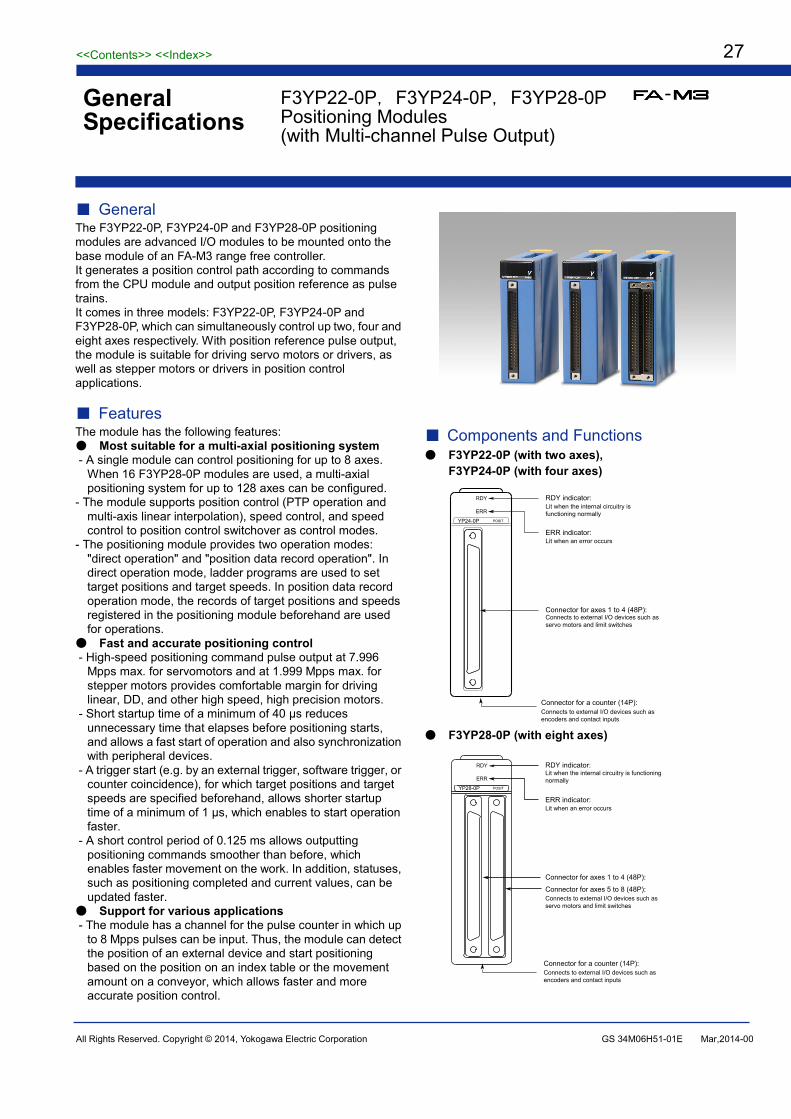
General The F3YP22-0P, F3YP24-0P and F3YP28-0P positioning modules are advanced I/O modules to be mounted onto the base module of an FA-M3 range free controller. It generates a position control path according to commands from the CPU module and output position reference as pulse trains. It comes in three models: F3YP22-0P, F3YP24-0P and F3YP28-0P, which can simultaneously control up two, four and eight axes respectively. With position reference pulse output, the module is suitable for driving servo motors or drivers, as well as stepper motors or drivers in position control applications.
Features The module has the following features: Most suitable for a multi-axial positioning system - A single module can control positioning for up to 8 axes.
When 16 F3YP28-0P modules are used, a multi-axial positioning system for up to 128 axes can be configured.
- The module supports position control (PTP operation and multi-axis linear interpolation), speed control, and speed control to position control switchover as control modes.
- The positioning module provides two operation modes: "direct operation" and "position data record operation". In direct operation mode, ladder programs are used to set target positions and target speeds. In position data record operation mode, the records of target positions and speeds registered in the positioning module beforehand are used for operations.
Fast and accurate positioning control - High-speed positioning command pulse output at 7.996
Mpps max. for servomotors and at 1.999 Mpps max. for stepper motors provides comfortable margin for driving linear, DD, and other high speed, high precision motors.
- Short startup time of a minimum of 40 μs reduces unnecessary time that elapses before positioning starts, and allows a fast start of operation and also synchronization with peripheral devices.
- A trigger start (e.g. by an external trigger, software trigger, or counter coincidence), for which target positions and target speeds are specified beforehand, allows shorter startup time of a minimum of 1 μs, which enables to start operation faster.
- A short control period of 0.125 ms allows outputting positioning commands smoother than before, which enables faster movement on the work. In addition, statuses, such as positioning completed and current values, can be updated faster.
Support for various applications - The module has a channel for the pulse counter in which up
to 8 Mpps pulses can be input. Thus, the module can detect the position of an external device and start positioning based on the position on an index table or the movement amount on a conveyor, which allows faster and more accurate position control.
Components and Functions F3YP22-0P (with two axes),
F3YP24-0P (with four axes)
RDY indicator:Lit when the internal circuitry is functioning normally
ERR indicator:Lit when an error occurs
Connector for axes 1 to 4 (48P):Connects to external I/O devices such as servo motors and limit switches
RDY
ERR
POSITYP24-0P
Connector for a counter (14P):Connects to external I/O devices such as encoders and contact inputs
F3YP28-0P (with eight axes)
RDY indicator:Lit when the internal circuitry is functioning normally
ERR indicator:Lit when an error occurs
Connector for axes 1 to 4 (48P):
Connector for axes 5 to 8 (48P):Connects to external I/O devices such as servo motors and limit switches
RDY
ERR
POSITYP28-0P
Connector for a counter (14P):Connects to external I/O devices such as encoders and contact inputs
F3YP22-0P,F3YP24-0P,F3YP28-0P Positioning Modules (with Multi-channel Pulse Output)
General Specifications
<<Contents>> <<Index>> 28
All Rights Reserved. Copyright © 2014, Yokogawa Electric Corporation GS 34M06H51-01E Mar,2014-00
Specifications
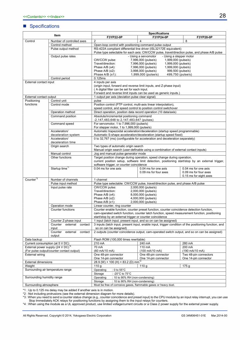
Item Specifications F3YP22-0P F3YP24-0P F3YP28-0P
Control Number of controlled axes 2 4 8 Control method Open-loop control with positioning command pulse output Pulse output method RS-422A compliant differential line driver (ISL32172E equivalent)
Pulse type selectable for each axis: CW/CCW pulse, travel/direction pulse, and phase A/B pulse Output pulse rates
- Using a servomotor - Using a stepper motor CW/CCW pulse: 7,996,000 (pulse/s) 1,999,000 (pulse/s) Travel/direction: 7,996,000 (pulse/s) 1,999,000 (pulse/s) Phase A/B (x4): 7,996,000 (pulse/s) 1,999,000 (pulse/s) Phase A/B (x2): 3,998,000 (pulse/s) 999,500 (pulse/s) Phase A/B (x1): 1,999,000 (pulse/s) 499,750 (pulse/s)
Control period 0.125ms External contact input
4 inputs per axis (origin input, forward and reverse limit inputs, and Z-phase input) ( A digital filter can be set for each input. Forward and reverse limit inputs can be used as generic inputs.)
External contact output 1 output per axis (deviation pulse clear signal) Positioning functions
Control unit pulse Control mode Position control (PTP control, multi-axis linear interpolation),
speed control, and speed control to position control switchover Operation method Direct operation, position data record operation (10 data/axis) Command position Absolute/incremental positioning command
-2,147,483,648 to 2,147,483,647 (pulses) Command speed For servomotor, 1 to 7,996,000 (pulse/s)
For stepper motor, 1 to 1,999,000 (pulse/s) Acceleration/ deceleration system
Automatic trapezoidal acceleration/deceleration (startup speed programmable) Automatic S-shape acceleration/deceleration (startup speed fixed)
Acceleration/ deceleration time
0 to 32,767 (ms) (configurable for acceleration and deceleration separately)
Origin search Two types of automatic origin search Manual origin search (user-definable using a combination of external contact inputs)
Manual control Jog and manual pulse generator mode Other functions Target position change during operation, speed change during operation,
current position setup, software limit detection, positioning start/stop by an external trigger, software trigger, or counter coincidence
Startup time*1 0.04 ms for one axis
0.04 ms for one axis 0.09 ms for four axes
0.04 ms for one axis 0.09 ms for four axes 0.15 ms for eight axes
Counter*3 Number of channels 1 channel
Pulse input method Pulse type selectable: CW/CCW pulse, travel/direction pulse, and phase A/B pulse Input pulse rate CW/CCW pulse: 2,000,000 (pulse/s)
Travel/direction: 2,000,000 (pulse/s) Phase A/B (x4): 8,000,000 (pulse/s) Phase A/B (x2): 4,000,000 (pulse/s) Phase A/B (x1): 2,000,000 (pulse/s)
Operation mode Linear counter, ring counter Counter functions Counter enable function, counter preset function, counter coincidence detection function,
cam-operated switch function, counter latch function, speed measurement function, positioning start/stop by an external trigger or counter coincidence
Counter Z-phase input 1 input (latch input, present input, and so on can be assigned) Counter external contact input
3 inputs (latch input, present input, enable input, trigger condition of the positioning function, and so on can be assigned)
Counter external contact output
2 outputs (counter coincidence output, cam-operated switch output, and so on can be assigned)
Data backup Flash ROM (100,000 times rewritable) Current consumption (at 5 V DC) 210 mA 240 mA 280 mA External power supply (24 V DC)*4
(For pulse output/counter contact output) 70 mA (60 mA/10 mA)
110 mA (100 mA/10 mA)
200 mA (190 mA/10 mA)
External wiring One 48-pin connector One 14-pin connector
One 48-pin connector One 14-pin connector
Two 48-pin connectors One 14-pin connector
External dimensions 28.9 (W) × 100 (H) × 83.2 (D) mm*2
Weight 110 g 110 g 175 g Surrounding air temperature range Operating :0 to 55°C
Storage :-20°C to 75°C Surrounding humidity range Operating :10 to 90% RH (non-condensing)
Storage :10 to 90% RH (non-condensing) Surrounding atmosphere Must be free of corrosive gases, flammable gases or heavy dust.
*1 : Up to 0.125 ms delay may be added if another axis is in motion. *2 : Not including protrusions (see the external dimension diagram for more details). *3 : When you need to send a counter status change (e.g., counter coincidence and preset input) to the CPU module by an input relay interrupt, you can use
Stop Immediately ACK relays for positioning functions by assigning them to the input relays for counters. *4 : When using the module as a UL approved product, use limited voltage/current circuits or a Class 2 power supply for the external power supply.

<<Contents>> <<Index>> 29
All Rights Reserved. Copyright © 2014, Yokogawa Electric Corporation GS 34M06H51-01E Mar,2014-00
External Connection Diagram Connector for position control
RDY
ERR
POSITYP22-0P
RDY
ERR
POSITYP24-0P
RDY
ERR
POSITYP28-0P
24b Axis 4 Z-phase input (-) 24a Axis 2 Z-phase input (-) 24b Axis 8 Z-phase input (-) 24a Axis 6 Z-phase input (-) 23b Axis 4 Z-phase input (+) 23a Axis 2 Z-phase input (+) 23b Axis 8 Z-phase input (+) 23a Axis 6 Z-phase input (+) 22b Axis 4 pulse output A (+) 22a Axis 2 pulse output A (+) 22b Axis 8 pulse output A (+) 22a Axis 6 pulse output A (+) 21b Axis 4 pulse output A (-) 21a Axis 2 pulse output A (-) 21b Axis 8 pulse output A (-) 21a Axis 6 pulse output A (-) 20b Axis 4 pulse output B (+) 20a Axis 2 pulse output B (+) 20b Axis 8 pulse output B (+) 20a Axis 6 pulse output B (+) 19b Axis 4 pulse output B (-) 19a Axis 2 pulse output B (-) 19b Axis 8 pulse output B (-) 19a Axis 6 pulse output B (-) 18b Axis 4 deviation pulse clear 18a Axis 2 deviation pulse clear 18b Axis 8 deviation pulse clear 18a Axis 6 deviation pulse clear 17b Pulse output GND*2 17a Pulse output GND*2 17b Pulse output GND*2 17a Pulse output GND*2 16b Axis 3 Z-phase input (-) 16a Axis 1 Z-phase input (-) 16b Axis 7 Z-phase input (-) 16a Axis 5 Z-phase input (-) 15b Axis 3 Z-phase input (+) 15a Axis 1 Z-phase input (+) 15b Axis 7 Z-phase input (+) 15a Axis 5 Z-phase input (+) 14b Axis 3 pulse output A (+) 14a Axis 1 pulse output A (+) 14b Axis 7 pulse output A (+) 14a Axis 5 pulse output A (+) 13b Axis 3 pulse output A (-) 13a Axis 1 pulse output A (-) 13b Axis 7 pulse output A (-) 13a Axis 5 pulse output A (-) 12b Axis 3 pulse output B (+) 12a Axis 1 pulse output B (+) 12b Axis 7 pulse output B (+) 12a Axis 5 pulse output B (+) 11b Axis 3 pulse output B (-) 11a Axis 1 pulse output B (-) 11b Axis 7 pulse output B (-) 11a Axis 5 pulse output B (-) 10b Axis 3 deviation pulse clear 10a Axis 1 deviation pulse clear 10b Axis 7 deviation pulse clear 10a Axis 5 deviation pulse clear 9b Deviation pulse clear GND*2 9a Deviation pulse clear GND*2 9b Deviation pulse clear GND*2 9a Deviation pulse clear GND*2 8b External power supply 24 Vin*1 8a External power 24 Vin (GND)*1 8b External power supply 24 Vin*1 8a External power 24 Vin (GND)*1 7b Axis 4 origin input 7a Axis 2 origin input 7b Axis 8 origin input 7a Axis 6 origin input 6b Axis 4 forward limit input 6a Axis 2 forward limit input 6b Axis 8 forward limit input 6a Axis 6 forward limit input 5b Axis 4 reverse limit input 5a Axis 2 reverse limit input 5b Axis 8 reverse limit input 5a Axis 6 reverse limit input 4b Axis 3 origin input 4a Axis 1 origin input 4b Axis 7 origin input 4a Axis 5 origin input 3b Axis 3 forward limit input 3a Axis 1 forward limit input 3b Axis 7 forward limit input 3a Axis 5 forward limit input 2b Axis 3 reverse limit input 2a Axis 1 reverse limit input 2b Axis 7 reverse limit input 2a Axis 5 reverse limit input 1b Contact input common*2 1a Contact input common*2 1b Contact input common*2 1a Contact input common*2
*1 : The external power supply 24 V is common to all axes. Connect one of two connectors or both connectors to the same power supply. *2 : Four contact input commons, four deviation pulse clear GNDs, and four pulse output GNDs are connected, respectively, in the module. *3 : The F3YP22-0P module does not support three and four axes. Never wire the pins for three and four axes on this module. Connector for pulse counter
1 Counter input A (+) 8 Counter contact output 1
2 Counter input A (-) 9 External power supply 24 Vin (GND)
3 Counter input B (+) 10 Counter contact output 2 4 Counter input B (-) 11 External power supply 24 Vin 5 Counter Z-phase input (+) 12 Counter contact input 1 6 Counter Z-phase input (-) 13 Counter contact input 2
7 Counter contact input plus common
14 Counter contact input 3

<<Contents>> <<Index>> 30
All Rights Reserved. Copyright © 2014, Yokogawa Electric Corporation GS 34M06H51-01E Mar,2014-00
Electrical Characteristics Pulse output
Item Specifications Isolation method Isolated coupler
Electrical specification RS-422 compliant differential line driver (ISL32172E or equivalent)
Maximum speed 7,996,000pps
External power supply 24 V DC (with external power monitoring function)
Pulse output type Output A Output B
CW/CCW CW signal CCW signal Travel/direction Travel signal Direction signal
Phase A/Phase B Phase A signal Phase B signal
- : Make sure that the polarity of the ‘+’ signal and ‘-‘ signal during signal
off matches the specification of the target driver. When connected with reverse polarities, the driver may not operate.
- : Always check the polarity of the external power supply (24 V DC). Connecting with reverse polarities may damage the internal circuitry of the positioning module.
External contact input
Item Specifications Isolation method Photocoupler isolation Input impedance about 7.4 kΩ Rated input voltage (allowable input voltage range)
24 V DC (20.4 to 26.4 V DC)
Rated input current 3.1 mA Voltage/current for ON signal (for NO contact) 19.2 V DC min./ 2.4 mA min.
Voltage/current for OFF signal (for NO contact) 5.8 V DC max./ 0.9 mA max.
Common type Shared common Response time*
(for NO contact) OFF → ON : 0.4 ms max. ON → OFF : 2.0 ms max.
* : The filter time set in the registered parameters is added to this value.
Signal Pins Off (break) On (mark)
Output (+)
High level (differential positive)
Low level (differential negative)
Output (-)
Low level (differential negative)
High level (differential positive)
14a
13aPulse Output A+
Pulse Output B+
24VDCExternal 24 V in
External 24 V in (GND)
12a
11a
8a
8b
Pulse Output A-
Pulse Output B-
External Power Monitoring
Pulse Output
DC/DC
17a Pulse Output GND
Forward Reverse
CW (output A)ON
OFF
OFF
ONCCW (output B)
ON
OFF
OFF
ON
Travel (output A)
Direction (output B)
Forward Reverse
ON
OFF
OFF
ON
Phase A (output A)
Phase B (output B)
Forward Reverse
1a : Contact input COM
2a : Reverse limit input
24 V DC
+ -
+-
4a : Origin input
3a : Forward limit input

<<Contents>> <<Index>> 31
All Rights Reserved. Copyright © 2014, Yokogawa Electric Corporation GS 34M06H51-01E Mar,2014-00
Deviation pulse clear signal output Item Specifications
Isolation method Photocoupler isolation Rated load voltage 24 V DC
Maximum load current 100 mA per contact ( 200 mA per common line)
OFF leakage current 0.1 mA max. ON residual voltage 1.5 V DC max. Common type Shared common
Encoder Z-phase input
Item Specifications Isolation method Photocoupler isolation Input impedance 240 Ω Rated input voltage (allowable input voltage range)
5 V DC (4.25 to 5.5 V DC)
Rated input current 15.3 mA Voltage/current for ON signal (for NO contact) 3.5 V DC min./ 9 mA min.
Voltage/current for OFF signal (for NO contact) 1.5 V DC max./ 2 mA max.
Common type Separate common Response time* 0.125 ms max.
* : The filter time set in the registered parameters is added to this value. Counter input
Item Specifications Isolation method Photocoupler isolation Input impedance 240 Ω Rated input voltage (allowable input voltage range)
5 V DC (4.25 to 5.5 V DC)
Rated input current 15.3 mA Voltage/current for ON signal (for NO contact) 3.5 V DC min./9 mA min.
Voltage/current for OFF signal (for NO contact) 1.5 V DC max./2 mA max.
Input pulse rate 8,000,000 pps Common type Separate commons
- : When connecting the counter input to the encoder of a motor or driver, ensure that the Phase A/Phase B specification of the motor/driver and that of the positioning module agree with each other. To do so, confirm the relationship between the rotating direction and the phases of an encoder by referring to the user's manual, and connect the encoder to the counter input such that the counter Phase B input terminal receives pulses earlier than the counter Phase A input terminal if the encoder rotates in the forward direction.
Forward Reverse
CW (counter input A)ON
OFF
OFF
ONCCW (counter input B)
ON
OFF
OFF
ON
Phase A (counter input A)
Phase B (counter input B)
Forward Reverse
1 : Counter input A (+)
2 : Counter input A (-)
3 : Counter input B (+)
4 : Counter input B (-)
ON
OFF
OFF
ON
Travel (counter input A)
Direction (counter input B)
Forward Reverse
15a : Encoder Z-phase input (+)
16a : Encoder Z-phase input (-)
10a : Deviation pulse clear output
9a : Deviation pulse clear output (GND)

<<Contents>> <<Index>> 32
All Rights Reserved. Copyright © 2014, Yokogawa Electric Corporation GS 34M06H51-01E Mar,2014-00
Counter contact input Item Specifications
Isolation method Photocoupler isolation Input impedance about 3.45 kΩ Rated input voltage (allowable input voltage range)
24 V DC (20.4 to 26.4 V DC)
Rated input current 6.5 mA Voltage/current for ON signal (for NO contact) 19.2 V DC min./ 2.4 mA min.
Voltage/current for OFF signal (for NO contact) 5.8 V DC max./ 0.9 mA max.
Common type Shared common (positive common)
Response time* 0.01 ms max.
* : The filter time set in the registered parameters is added to this value. Counter contact output
Item Specifications Isolation method Isolated coupler Rated load voltage 24 V DC Maximum load current 100 mA per contact OFF leakage current 0.1 mA max. ON residual voltage 1.5 V DC max. Common type Shared common External power supply* 24 V DC Response time 0.01 ms max.
* : When using counter contact output, please connect the external power supply (24 V DC) also to counter connector.
Counter Z-phase input
Item Specifications Isolation method Photocoupler isolation Input impedance 240 Ω Rated input voltage (allowable input voltage range)
5 V DC (4.25 to 5.5 V DC)
Rated input current 15.3 mA Voltage/current for ON signal (for NO contact) 3.5 V DC min./ 9 mA min.
Voltage/current for OFF signal (for NO contact) 1.5 V DC max./2 mA max.
Common time Separate commons Response time* 0.01 ms max.
* : The filter time set in the registered parameters is added to this value.
5 : Counter Z-phase input (+)
6 : Counter Z-phase input (-)
L
8 : Counter contact output 1
11 : External power supply input
9 : External power supply input (GND)
24VDC
+
-
IsolationCoupler L
10 : Counter contact output 2
Constant voltage circuit
7 : Counter contact input COM (positive common)
12 : Counter contact input 1
24 V DC
+ -
14 : Counter contact input 3
13 : Counter contact input 2

<<Contents>> <<Index>> 33
All Rights Reserved. Copyright © 2014, Yokogawa Electric Corporation GS 34M06H51-01E Mar,2014-00
Model and Suffix Codes Model Suffix
code Style code
Option code Description
F3YP22 -0P ・・・・・・ ・ ・ ・ ・ ・・
2-axis control, 7.996 Mpps max. (for servomotor) or 1.999 Mpps max. (for stepper motor) One counter channel for encoder input, 8 Mpps max. Position control/speed control/switching between speed and position control, direct operation/position data record operation
F3YP24 -0P ・ ・ ・ ・ ・・
・ ・ ・ ・ ・・
4-axis control, 7.996 Mpps max. (for servomotor) or 1.999 Mpps max. (for stepper motor) One counter channel for encoder input, 8 Mpps max. Position control/speed control/switching between speed and position control, direct operation/position data record operation
F3YP28 -0P ・ ・ ・ ・ ・・
・ ・ ・ ・ ・・
8-axis control, 7.996 Mpps max. (for servomotor) or 1.999 Mpps max. (for stepper motor) One counter channel for encoder input, 8 Mpps max. Position control/speed control/switching between speed and position control, direct operation/position data record operation
Operating Environment The positioning module can be used with all models of CPU modules.
Applicable External Interface Connectors Connector for positioning control (Fujitsu Component Limited)
Connection Connection Connection Soldered FCN-361J048-AU conector
FCN-360C048-B conector cover
Purchase the desired connector kit separately. Crimp-on
FCN-363J048 housing FCN-363J-AU contacts FCN-360C048-B conector cover
Pressure welded FCN-367J048-AU/F
Connector for pulse counter (Sumitomo 3M Limited) Connection Connection Connection
Soldered 10114-3000PE conector 10314-52F0-008 conector cover Purchase the desired
connector kit separately. Pressure welded
10114-6000EL conector 10314-52F0-008 conector cover
External Dimensions
83.2 28.92
1.3
100
Unit : mm
Note : The above diagram is for the F3YP28-0P module.

<<Contents>> <<Index>> 34
All Rights Reserved. Copyright © 2014, Yokogawa Electric Corporation GS 34M06H51-01E Mar,2014-00
Function Overview 1. Concept of Position Control The positioning module generates a position control path according to commands (with specified target positions, speeds, acceleration/deceleration time, etc.) from the CPU module and outputs positioning command values in the form of pulse trains. The number of output pulses determines the angle through which a motor rotates and the frequency of output pulses determines the speed at which a motor rotates. Based on the pulse trains from the module and feedback pulse trains from an encoder, a servomotor/servo driver adjusts the position and speed and passes a driving current to rotate the motor.
When the module stops pulse outputs, as the difference between the number of pulses output from the module and the number of pulses fed back from the encoder becomes small, the rotation speed decreases, and finally when the difference becomes zero, the motor stops. Position control concept of the positioning module:
Motor
Encoder
Positioning module Servo driver
Counter
Position servo
computation
Speed servo
computationCPU
module
Pulse output
Path generation Counter
Speed detector
Counter
External encoder
Speed
Time
Acceleration time
Deceleration time
Target speed
Remaining travel to the target position
(area of the trapezium)
Time
Position
Positioning command output
pulse value
Position of the motor
Positioning completed
Delay in reaching the target position
2. Counter Functions The module supports connecting a sensor such as an incremental encoder and has a counter input channel that allows input at up to 8 Mpps, three high-speed contact inputs for the counter, and two high-speed contact outputs for the counter. General counter functions, such as the counter enable/disable control function, counter coincidence detection function (two channels), counter latch function (two channels), and counter preset function, are available. A change in counter input states can be used as a trigger condition for a positioning operation. When the counter functions are
used in a positioning operation, the module can detect the position of an external device and start positioning based on the position on an index table or the movement amount on a conveyor.
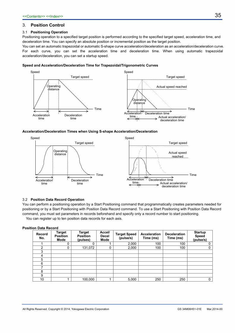
<<Contents>> <<Index>> 35
All Rights Reserved. Copyright © 2014, Yokogawa Electric Corporation GS 34M06H51-01E Mar,2014-00
3. Position Control 3.1 Positioning Operation Positioning operation to a specified target position is performed according to the specified target speed, acceleration time, and deceleration time. You can specify an absolute position or incremental position as the target position. You can set an automatic trapezoidal or automatic S-shape curve acceleration/deceleration as an acceleration/deceleration curve. For each curve, you can set the acceleration time and deceleration time. When using automatic trapezoidal acceleration/deceleration, you can set a startup speed. Speed and Acceleration/Deceleration Time for Trapezoidal/Trigonometric Curves
Time
Target speed
Acceleration time
Deceleration time
Operating distance
Target speed
Time
Speed
Acceleration time
Deceleration time
Operating distance
Actual speed reached
Actual acceleration/deceleration time
Speed
Acceleration/Deceleration Times when Using S-shape Acceleration/Deceleration
SpeedTarget speed
Time
Acceleration time
Deceleration time
Time
SpeedTarget speed
Actual speed reached
Acceleration time
Deceleration timeActual acceleration/deceleration time
Operating distance
3.2 Position Data Record Operation You can perform a positioning operation by a Start Positioning command that programmatically creates parameters needed for positioning or by a Start Positioning with Position Data Record command. To use a Start Positioning with Position Data Record command, you must set parameters in records beforehand and specify only a record number to start positioning.
You can register up to ten position data records for each axis. Position Data Record
Record No.
Target Position
Mode
Target Position (pulses)
Accel/ Decel Mode
Target Speed (pulse/s)
Acceleration Time (ms)
Deceleration Time (ms)
Startup Speed
(pulse/s) 1 0 0 1 2,000 100 100 0 2 0 131,072 0 2,000 100 100 0 3 4 5 6 7 8 9
10 1 100,000 1 5,000 250 250 0

<<Contents>> <<Index>> 36
All Rights Reserved. Copyright © 2014, Yokogawa Electric Corporation GS 34M06H51-01E Mar,2014-00
3.3 Multi-axis Linear Interpolated Operation To perform a linear-interpolated operation, set the target position, target speed, acceleration time, and deceleration time, and
execute a Start Positioning command (or a Start Positioning with Position Data Record command) simultaneously for all axes to be interpolated. In this operation, set the same acceleration and deceleration times to all axes concerned. Set the startup speed for all axes concerned to 0, and then calculate and set the ratio of the target speeds of those axes so that it equals to the ratio of the travels of those axes. Multi-axis Linear Interpolated Operation (Example of Biaxial Operation)
Time
Speed
Target speed of X axis
Acceleration time Deceleration time
Travel of X axis
X axis
Y axis
Travel of X axis
Travel of Y axis
Target speed of Y axis
3.4 Target Position Change Operation You can change the target position during a positioning operation. The Change Target Position command cannot change the
target speed, acceleration, or deceleration. If a Change Target Position command is issued during acceleration/deceleration or a change in speed, the execution of the command is suspended until the start of the constant-speed operation or until the axis stops. When the Change Target Position command is being executed, no commands other than Decelerate-and-Stop and Stop Immediately are available. You can use a position data record for target position change operation. Behavior When the Target Position Is Changed
Time
Speed
Start↑ ↑Request to change
target position
Time
Speed
Start↑Request to change
target position
↑
3.5 Positioning Operation with Resetting Current Position You can perform positioning operation after setting the current position to "0". By executing a single command, you can execute a Set Current Position command to write "0" for the current position and then execute a Start Positioning command.
This operation is useful for control that repeats an operation in a single direction because it can avoid an overflow error that occurs if the operating range (32 bit) of the positioning module is exceeded. Positioning Operation with Resetting Current Position
Time
Speed
↑Target position (position: 1000)
Target position (position: 1000)
↑↑Start positioning with
resetting current position (position: 0)
↑Start positioning with
resetting current position (position: 0)

<<Contents>> <<Index>> 37
All Rights Reserved. Copyright © 2014, Yokogawa Electric Corporation GS 34M06H51-01E Mar,2014-00
3.6 Target Position Change with Resetting Current Position You can perform a positioning operation with Resetting Current Position during a positioning operation. This operation changes the current position so that the current target position becomes "0", and then performs a positioning operation toward the new target position.
The target position can be set only to a positive value during a forward operation or a negative value during a reverse operation. (Note that the operation direction cannot be changed in a target position change operation.) Target Position Change Operation with Resetting Current Position
Time
Speed
↑Start
positioning
↑Change target position with resetting current
position (position: 600)
Time
Speed
↑
↑Target position (position: 1000)
↑Target position (position: 1200)
↑Last target
position (position: 0)
↓ During a positioning operation toward the target position 1000, when the current position is 600 (and remaining travel is 400), a request occurs to change the target position to 1200 with a current position reset.
Changing the target position (The current position is a negative value.)
Change target position with resetting current
position (position: -400)

<<Contents>> <<Index>> 38
All Rights Reserved. Copyright © 2014, Yokogawa Electric Corporation GS 34M06H51-01E Mar,2014-00
4. Speed Control 4.1 Speed Control Operation This operation moves an axis continuously in a single direction according to the specified target speed, acceleration time, and deceleration time.
You can set an automatic trapezoidal or automatic S-shape acceleration/deceleration as an acceleration/deceleration curve. For each curve, you can set the acceleration time and deceleration time. When using automatic trapezoidal acceleration/deceleration, you can set a startup speed. You can request to change the speed during a speed control operation. Behavior When Speed Control Starts and Speed Changes Are Requested
Time
Speed
↑Request to
change speed
↑Request to
change speed
↑Request to
change speed
↑Request to
decelerate and stop
4.2 Speed Control to Position Control Switchover During a speed control operation, you can specify a target position (travel distance) so that the operation can stop at the target position. When speed control is switched to position control, the current position is set to "0".
Switchover to position control can be set to be performed not only when a command request occurs from the CPU module but also when an edge input occurs for the encoder Z-phase. ・Speed Control to Position Control Switchover (without Z-phase counts)
Request to switch to position control
Time
Speed
↑
Target position (travel)
Speed control Position control
・Speed Control to Position Control Switchover (with Z-phase counts, two rising edges)
Speed
Request to switch to position control
↑
Target position (travel)
Z-phase
Time
Speed control Position control

<<Contents>> <<Index>> 39
All Rights Reserved. Copyright © 2014, Yokogawa Electric Corporation GS 34M06H51-01E Mar,2014-00
5. Origin Search There are two ways to perform origin search: automatic and manual. In automatic origin search, the origin search behavior is
defined by registered parameters. In manual origin search, the origin search behavior is arbitrarily defined by an application program.
5.1 Automatic Origin Search The automatic origin search has two modes: mode 0 and mode 1. Mode 0 uses the origin switch input, whilst mode 1 does not
use the origin switch input but uses the forward/reverse limit switch input instead. In Z-phase detection, when the number of Z-phase pulses defined in the AOS Z-phase Search Count parameter is detected,
the axis stops immediately. The stop position is defined as the origin (the value of the origin is defined in the AOS Offset parameter). A deviation pulse clear signal is then output for a period specified in the AOS Deviation Pulse Clear Time parameter. ・Automatic Origin Search (0: Origin input is used)
Forward limit Reverse limitOrigin
Startup speed
Search speed 1
Search speed 2
Z-phase pulse
・Automatic Origin Search (1: Origin input is not used)
Forward limit Reverse limit
Startup speed
Search speed 1
Search speed 2
Z-phase pulse
5.2 Manual Origin Search In manual origin search, the module searches for the origin according to the command parameter values as it detects changes in external contact inputs. When the required change is detected, it either stops or shifts to Z-phase search. If configured to perform Z-phase search, the module counts the number of Z-phase pulses defined by the Z-phase Search Count parameter, and then stops the axis immediately. The stop position is taken as the origin. The module then outputs a deviation pulse clear signal for a duration defined by the Deviation Pulse Clear Time parameter. If the Z-phase Search Count is set to 0, no deviation pulse clear signal is generated.
To perform an origin search at two different speeds or to change the operation direction according to the state of an external contact input detected during origin search, split the origin search process into different phases, varying the parameters for each phase, and perform manual search operations. This strategy allows you to customize your origin-search operation to a desired search pattern. Manual Origin Search
Rise in contact input
When "Ignore" is specified
When "Z-phase Search" is specified
When "Decelerate & Stop" is specified
When "Stop Immediately" is specified
Stop when a Z-phase is detected

<<Contents>> <<Index>> 40
All Rights Reserved. Copyright © 2014, Yokogawa Electric Corporation GS 34M06H51-01E Mar,2014-00
6. Manual Control 6.1 Jog You can use a jog operation to operate a motor manually.
You can specify the target speed, acceleration time, and deceleration time for a jog operation, or even change the speed during a jog operation. Jog Operation
Speed
Time
Forward jog
Start
End
6.2 Manual Pulse Generator Mode In manual pulse generator mode, you can operate a motor manually by using a manual pulse generator connected to the counter input. The number of input pulses of a manual pulse generator and the movement amount for a motor satisfy the following relational expression:
Motor movement amount = Number of input pulses × Manual Pulse Generator M Value / Manual Pulse Generator N Value
You can set a value between 1 through 32,767 for the Manual Pulse Generator M Value and Manual Pulse Generator N Value. You can also set a first order lag filter for the counter input. Manual Pulse Generator Mode
Speed
Time
Manual pulse generator input
Target speed
Actual output
7. Speed Change Operation You can change the operation speed during a positioning operation, speed control operation, or jog operation.
Changing Speed during a Positioning Operation
Time
Speed
Start↑ ↑ ↑Request to
change speedRequest to
change speed
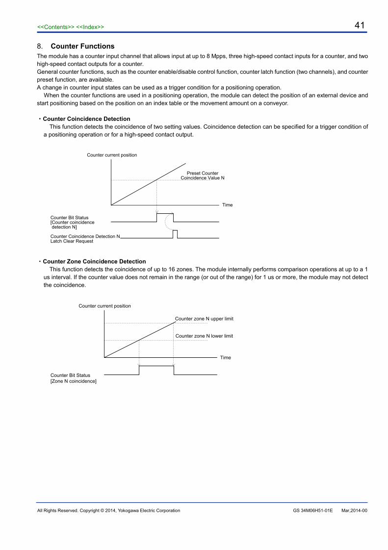
<<Contents>> <<Index>> 41
All Rights Reserved. Copyright © 2014, Yokogawa Electric Corporation GS 34M06H51-01E Mar,2014-00
8. Counter Functions The module has a counter input channel that allows input at up to 8 Mpps, three high-speed contact inputs for a counter, and two high-speed contact outputs for a counter. General counter functions, such as the counter enable/disable control function, counter latch function (two channels), and counter preset function, are available. A change in counter input states can be used as a trigger condition for a positioning operation.
When the counter functions are used in a positioning operation, the module can detect the position of an external device and start positioning based on the position on an index table or the movement amount on a conveyor. ・Counter Coincidence Detection
This function detects the coincidence of two setting values. Coincidence detection can be specified for a trigger condition of a positioning operation or for a high-speed contact output.
Counter current position
Counter Bit Status [Counter coincidence detection N]
Time
Preset Counter Coincidence Value N
Counter Coincidence Detection N Latch Clear Request
・Counter Zone Coincidence Detection
This function detects the coincidence of up to 16 zones. The module internally performs comparison operations at up to a 1 us interval. If the counter value does not remain in the range (or out of the range) for 1 us or more, the module may not detect the coincidence.
Counter current position
Counter Bit Status [Zone N coincidence]
Time
Counter zone N lower limit
Counter zone N upper limit

<<Contents>> <<Index>> 42
All Rights Reserved. Copyright © 2014, Yokogawa Electric Corporation GS 34M06H51-01E Mar,2014-00
9. Trigger Functions You can specify a trigger condition for a positioning operation, speed control operation, or decelerate and stop operation.
You must issue a command with a trigger beforehand in the same procedure as the standard command, and when the trigger occurs, the specified operation starts immediately Trigger Functions
Speed
Execute Command output relay
Time
Execute Command ACK input relay
"Waiting for trigger input" status
Satisfaction of the trigger condition
Positioning Completed input relay
・Software Trigger
A trigger can be activated by an application program. When a WRITE instruction from the CPU module writes "1" to the trigger-specific "Software Trigger Request" parameter, the trigger is activated.
・External Contact Input Trigger
A trigger can be activated when an external contact input is ON for an axis. You can use a reverse limit input, forward limit input, or origin input for the external contact input.
・Counter Status Trigger
A trigger can be activated by a status change of a counter function. You can use, for example, the ON status of counter coincidence detection 1 and 2, or the ON status of counter contact inputs
1 to 3. ・Counter Zone Coincidence Trigger
A trigger can be activated when the zone coincidence detection of a counter function is ON. You can specify Zone Coincidence Detection 1 to 16 as a trigger condition.
・Positioning Completed Input Relay Trigger
A trigger can be activated when a Positioning Completed input relay is ON for another axis.
10. Save to/Initialize Flash Memory ・Save to Flash Memory
After specifying parameters, you can save the parameters to the flash memory in this module. At power up or system reset, the content of the flash memory is automatically reloaded to the parameters.
Parameters to Be Saved
Registered parameters for each axis (parameters specified by a Set Registered Parameters command) Position data records Counter registered parameters (parameters specified with Counter Registered Parameters Request) Part of counter control parameters (Counter Preset Value, Preset Counter Coincidence Value 1 to 2, Counter Zone 1 to 16 Lower Limit/Upper Limit)
・Initialize Flash Memory
You can initialize the parameters saved in the flash memory to the factory defaults.