general design guidelines - university of california, …ae.ucdavis.edu/docs/csdg/design/2 design...
TRANSCRIPT

UC DAVIS Campus Standards & Design Guide
GENERAL DESIGN GUIDELINES The following guidelines apply to all new construction (including entire new buildings as well as remodels or additions to existing buildings) on the University of California at Davis (UCD) Campus. Some projects, due to specific project budgetary, regulatory, or program constraints may not be able to incorporate all of the guidelines listed below. Any questions as to applicability of these guidelines should be directed to the University’s Representative for clarification. For broad campus goals and Architectural Design Guidelines please see: http://www.ae.ucdavis.edu/projectsindesign/campus_standards.htm and click on “Architectural Design Guidelines.” This guide was prepared in 2003 and provides historical background on the development of the UC Davis campus, information on significant buildings and campus districts as well as architectural and site furniture design guidelines. Refer to all specific program requirements, Soils Reports (when furnished by the University), the Long Range Development Plan (LRDP), the LRDP Environmental Impact Report (EIR), project EIR, District Planning Guides, Architectural Design Guide and any other applicable guidelines in designing buildings and site improvements on the UCD campus, as well as the following requirements. ACCESSIBILITY Provide for disabled access to all sites and buildings as per the requirements of CCR Title 24 and the Americans with Disabilities Act of 1990 (ADA) accessibility guidelines, using the most stringent where the two conflict. SUSTAINABLE MATERIALS, PRODUCTS, AND EQUIPMENT Specify materials, products and equipment with the following attributes where they meet the performance goals needed for the project:
1. Materials, products and equipment that have an inherent ability to serve their function with minimal maintenance.
2. Materials, products or equipment that can be removed and re-used when they are no longer needed for the project.
3. Materials, products or equipment that create no or minimal health risks to the people who occupy, construct and maintain the project.
4. Materials, products or equipment that have significant post-industrial and post-consumer recycled content.
5. Local/regional materials and equipment manufactured or having final assembly at a facility within 500 miles of the Project.
6. Certified wood from manufacturers declaring conformance with Forest Stewardship Council Guidelines for certified wood building components.
PART II – DESIGN REQUIREMENTS 1 May 2005

UC DAVIS Campus Standards & Design Guide
SITE REQUIREMENTS See technical sections for additional requirements. SITE UTILITIES All significant Campus Core buildings shall be on campus central systems unless an exception is reviewed and approved by the University’s Representative.
STORM DRAINAGE Prevent concentrated roof storm water from flowing across pedestrian paths or walkways. Provide open clean-out areas at downspout/underground system junction. Implement structural Best Management Practices (BMPs) that will prevent pollution or provide treatment of storm water runoff to reduce pollutants after construction of the project is completed. Post-construction programs are most effective when they stress (i) low impact design; (ii) source controls; and (iii) treatment controls. Examples of BMPs for new development and redevelopment can be found in the California Stormwater Quality Association’s Stormwater Best Management Practice Handbook for New Development and Redevelopment (www.cabmphandbooks.com). If project site existing imperviousness is less than or equal to 50%, implement a stormwater management plan that:
1. Maintains annual groundwater recharge rates, promotes the use of nonstructural practices and infiltration, and captures and treats the volume from 90% of the average annual rainfall.
2. Addresses stream channel stability (e.g., prevents increases in critical erosive velocities during bankfull and near-bankfull storm events) and the frequency and magnitude of out-of-bank flooding (e.g., flow events that exceed the bankfull capacity of the channel and therefore must spill over into the floodplain)
OR If the project site existing imperviousness is greater than 50%, implement a stormwater management plan that:
1. Maintains annual groundwater recharge rates, promotes the use of nonstructural practices and infiltration, and captures and treats the volume of runoff from 90% of the average annual rainfall for all proposed impervious areas, and
2. Results in a decrease of runoff by 25% of the annual stormwater load falling on existing imperviousness. This reduction can be accomplished through a variety of measures, including: increasing perviousness of site, implementing stormwater management practices (nonstructural and structural), capturing rainwater for reuse, or other measures.
3. Results in a decrease of runoff from the site by 50% of the annual stormwater load falling on the site and addresses channel stability and the frequency and magnitude of flooding from 100% of the newly added impervious surfaces. This reduction can be
PART II – DESIGN REQUIREMENTS 2 May 2005

UC DAVIS Campus Standards & Design Guide
accomplished through a variety of measures, including: perviousness of site, stormwater management practices (nonstructural and structural), capture of rainwater for reuse or other measures.
Semi-arid watersheds receive between 15 and 35 inches of rainfall per year. For this calculation, the volume of runoff from 90% of the average annual rainfall is equivalent to the runoff from 0.75 inches of rainfall; structural BMPs used to treat runoff must be capable of removing 80% of the average annual post development total suspended solids (TSS) load based on existing field monitoring information. Structural practices are considered to meet these criteria if (1) they are designed in accordance with standards and specifications from a state of local program that has adopted these performance standards, or (2) there exists in-field performance monitoring data demonstrating compliance with the criteria. Data must conform to accepted protocol (e.g., Technology Acceptance Reciprocity Partnership (TARP), Washington State Department of Ecology) for BMP monitoring.
LANDSCAPE The design of each building complex should be sensitive to, and complementary of, any existing sensitive vegetation and mature specimen trees. The landscape design shall provide for bicycle parking and circulation as well as for pedestrian circulation. Heat Island Mitigation Provide shade (within 5 years of landscape installation) and/or use light-colored/high-albedo materials with a Solar Reflectance Index (SRI) of at least 29 for at least 50% of the site’s non-roof impervious surfaces, including parking areas, walkways, plazas, fire lanes, etc.; OR Place a minimum of 50% of parking spaces underground or covered by structured parking. See Appendix for SRI calculation requirements. Design Considerations for Existing Trees
1. All trees on campus are a prime natural asset and should be carefully protected. All new building should observe the following guidelines:
2. Whenever possible, avoid fill or excavations within the drip line of other species, to avoid suffocation and root cutting. Avoid placing utility lines through trees to be saved.
3. Establish finish grades on paving, footings etc., above the root system. The grade at the base of all trees should not be raised or lowered.
4. Limit root coverage to not more than 40 percent unless a loose permeable covering is used such as gravel, decomposed granite, etc.
5. Re-establish drainage systems around trees where natural drainage system has been disturbed. Finish grades should drain away from the tree.
General Planting Selection
1. Providing shady and sunny seating areas, colorful entries, and screening or buffers when necessary.
2. Plant sizes should be chosen to ensure long-term adaptability to specific site locations.
PART II – DESIGN REQUIREMENTS 3 May 2005

UC DAVIS Campus Standards & Design Guide
3. Coordinate proposed plant material with Grounds and Arboretum. 4. For planting guidelines (specifications for Nursery Tree Acceptance, Tree Planting Detail,
Planting Procedures and Tree Spacing), refer to “Treescapes at UC Davis - A Landscape Management Plan for the Tree-Lined Corridors.”
5. In order to reduce the potential for criminal activity, plant sizes should not inhibit a clear line of vision for users.
Maintenance
1. Plant materials should be selected for ease of maintenance so as not to require substantial pruning, leaf and litter collection or pest control.
2. Avoid large deciduous trees in interior courtyards that require substantial leaf collection. 3. Plants should be drought tolerant and low water use types.
Lawn Areas
1. When lawn areas are required, provide a few larger areas of lawn, as opposed to many small individual patches of lawn, in order to minimize maintenance costs.
2. In layout of lawn areas and other specialized landscape areas, consider the ease of lawn mower or other maintenance equipment access to such areas.
3. Do not use decomposed granite or gravel at paths within developed areas adjacent to buildings where such materials can contaminate or migrate onto lawn or building entry systems.
PARKING/CIRCULATION General Design
1. See Heat Island Mitigation section under the Landscaping section above for further requirements.
2. All parking areas near buildings on campus are to include a portion of the total spaces for handicapped parking as per the requirements of the DSA and CCR.
3. Parking should be convenient, but not obtrusive. Screening or buffering of parking areas is encouraged.
4. Pedestrian movement in and out of parking areas shall be incorporated into the landscape design.
5. Parking should not create an obstacle for pedestrians traveling through the campus core. 6. Parking and service areas shall be landscaped, retain existing trees where possible,
conform to the topography, and be limited in size to decrease their visual impact. 7. All parking areas or clusters of areas 1 acre or larger shall either be provided with
sedimentation/infiltration basins designed to capture the majority of suspended or emulsified contaminants.
8. Provide conduit stub-outs and pull strings for future installation of emergency phone and for ticket/permit dispensers.
9. Layout for parking should provide 5.4 parking spaces for every 10 occupants (staff, faculty and student) of the building.
10. Designate spaces for Disabled, Vendor/Diamond E, and Meter parking. Adequate signage shall be provided to identify designated spaces and identify the parking lot.
PART II – DESIGN REQUIREMENTS 4 May 2005

UC DAVIS Campus Standards & Design Guide
Minimum Parking Area Requirements
1. Provide wheel stops (curb may be used as a wheel stop). 2. Provide parking stalls with minimum dimensions of 8 feet-6 inches wide by 18 feet-0
inches long per space. Aisle width shall be a minimum 25 feet wide for 90 degree parking on both sides.
3. Compact parking spaces are not normally provided. 4. Motorcycle parking shall be provided as specified in the Detailed Project Program (DPP).
When provided, motorcycle parking shall be on a concrete pad. Vehicle/Bicycle/Pedestrian Circulation
1. Two lane roads are to be 24 ft. wide minimum, with minimum 30 ft. radius at curves. 2. Provide asphalt or concrete site paths of a width appropriate to its intended use. If
asphalt is used, provide pressure treated pathway headers. Verify with the University’s Representative.
3. Provide bicycle parking (to serve a minimum of 5% of the regular building occupancy) convenient to building entries and on the project site. Verify amount of bicycle parking with DPP.
4. Provide for bicycle circulation from bike paths to bike parking to pedestrian path to building entry. Bicycle and pedestrian paths shall be separate when possible.
SITE LIGHTING & ELECTRICAL The primary goals for campus lighting area safety, security and aesthetics: Only light areas where exterior lighting is clearly required for safety and security. Lighting used solely for aesthetic effects shall be used only to achieve campus wide way-finding goals.
1. Safety involves minimizing conflicts with pedestrians, bicycles, and vehicles through channeling traffic to the safest paths and providing adequate sight lines and lighting levels.
2. Security minimizes personal harm or property loss by achieving good visibility and by removing shadows along paths.
3. Aesthetics in lighting refers to the appearance and place making qualities of the lighting design, both during the day and night.
The campus lighting recommendations fall into seven application categories of lighting type and context. See Section 16550 – Exterior Lighting. WASTE COLLECTION SITING ISSUES Most buildings on campus are generally near an outside solid waste or recycling storage bin location, accessible by the campus solid waste and recycling collection trucks for periodic (usually daily) collections. All new buildings or building additions should consider convenient access locations to trash and recycling bins by building residents and Custodial personnel, as well as by Solid Waste and R4 Recycling collection trucks.
PART II – DESIGN REQUIREMENTS 5 May 2005

UC DAVIS Campus Standards & Design Guide
Balance convenience to users with desirable isolation of odors and visibility of trash bins when siting bins. For example, avoid placement near air intakes. Screen bin locations, whether by planting, wood fencing concrete walls, etc., depending on particular program requirements. Include continuing accessibility (for instance, growth of maturing plants) in screening plans.
PART II – DESIGN REQUIREMENTS 6 May 2005

UC DAVIS Campus Standards & Design Guide
BUILDING REQUIREMENTS ACCESS TO NATURAL LIGHT AND VIEWS Design the building to maximize interior day-lighting. Strategies to consider include building orientation, shallow floor plates, increased building perimeter, exterior and interior permanent shading devices, high performance glazing and photo-integrated light sensors. Achieve a minimum Daylight Factor of 2% (excluding all direct sunlight penetrations) or achieve at least 25 foot candles using a computer simulation model in 75% of all regularly occupied areas. Provide daylight redirection and/or glare control devices to ensure daylight effectiveness. Exceptions for areas where tasks would be hindered by the use of daylight will be identified in the project program. See Appendix for calculation requirements. Provide direct line of sight to vision glazing for building occupants in 90% of all regularly occupied areas (occupied by an individual for more than 4 hours daily). Exceptions will be identified in the project program. See Appendix for calculation requirements. ACOUSTICS All plumbing penetrations (bathroom, hydronic, etc.) in walls must be caulked airtight using specified acoustical caulk. Where recessed fixtures of any type are installed (e.g., medicine cabinets, fire extinguishers, electric distribution panels, recessed water fountain, recessed bookcases, etc.) ensure that required acoustic wall construction extends behind these recessed elements. Installation of noisemaking equipment (such as telephones, water fountains, etc.) is not allowed on walls of rooms requiring acoustic protection. Use surface mounted rather than recessed lighting fixtures and fans, etc. at ceilings of rooms requiring acoustical protection in order to minimize sound transfer. Space doors to rooms requiring acoustical protection so that neighboring rooms do not have directly adjoining doors and so that doors on opposite sides of corridors do not directly face each other. Stagger all doors. Do not place any doors to rooms requiring acoustical protection opposite stairwell or bathroom doors. Provide a maximum gap of 1/2 inch at all door bottoms (less when possible). Do not place bathrooms (public or private) or student lounges over rooms requiring acoustical protection (especially rooms having non-carpeted floors). Separate studs with a structural, in-wall air gap; must isolate the jamb of all heavily used corridor doors from any adjacent rooms requiring acoustical isolation.
PART II – DESIGN REQUIREMENTS 7 May 2005

UC DAVIS Campus Standards & Design Guide
Mechanical equipment in spaces above or below rooms requiring acoustic isolation must be vibration isolated, including piping and conduits, from walls, floors and ceilings. See General Mechanical section for additional acoustic requirements. HUMAN FACTORS Buildings on campus should be designed with awareness and sensitivity for human interaction with the built environment. Design Professionals are to consider scale, way-finding, and adequate clearances. Walkway canopies, railings and similar work shall be designed to reflect their exposure to student use for consideration in restricting climbing, loading, etc. INDOOR POLLUTANT REDUCTION AND CONTROL Adhesives, sealants, sealant primers and aerosol adhesives used inside the exterior weatherproofing system must not exceed the following requirements:
1. Adhesives, Sealants and Sealant Primers: South Coast Air Quality Management District (SCAQMD) Rule #1168 requirements in effect on January 1, 2003 and rule amendment date of October 3, 2003.
2. Aerosol Adhesives: Green Seal Standard GC-36 requirements in effect on October 19, 2000.
Paints and coatings used on the interior of the building and applied on-site must not exceed the VOC limits and must not include any of the chemical components limited or restricted by the following standards:
1. Topcoat Paints: Green Seal Standard GS-11, Paints, First Edition, May 20, 1993. 2. Anti-corrosive and Anti-rust Paints: Green Seal Standard GS-03, Anti-Corrosive Paints,
Second Edition, January 7, 1997. For applications on ferrous metal substrates. 3. All other Architectural Coatings, Primers and Undercoats: South Coast Air Quality
Management District (SCAQMD) Rule 1113, Architectural Coatings, rules in effect on January 1, 2004.
Carpets systems must not exceed the target emissions factors of the Carpet and Rug Institute’s: Green Label and Green Label Plus Program and Testing Procedures. Composite wood and agrifiber products, including core materials, must contain no added urea-formaldehyde resins. Adhesives used in field- and shop-fabricated assemblies containing these products must contain no urea-formaldehyde. Pollutant Control Design to minimize and control pollutant or biological contaminant entry into buildings and later cross-contamination of regularly occupied areas:
1. Employ permanent entryway systems (recessed walk-off mats or grates, etc.) to capture dirt, particulates, etc. from entering the building at all high volume entryways.
2. Where hazardous gases or chemicals may be present or used (including garages, housekeeping/laundry areas, and copying/printing rooms), provide segregated areas with deck to deck partitions with separate outside exhaust at a rate of at least 0.50 cubic feet
PART II – DESIGN REQUIREMENTS 8 May 2005

UC DAVIS Campus Standards & Design Guide
per minute per square foot, no air re-circulation, and operated at a negative pressure compared with the surrounding spaces of at least an average of 5 Pa (0.02 inches of water gauge) and with a minimum of 1 Pa (0.004 inches of water) when the doors to the rooms are closed.
3. Provide containment drains plumbed for appropriate disposal of hazardous liquid wastes in places where water and chemical concentrate mixing occurs for maintenance, or laboratory purposes.
4. Provide regularly occupied areas of the building with new air filtration media prior to occupancy that provides a Minimum Efficiency Reporting Value (MERV) of 13 or better.
LACTATION ROOMS Lactation rooms are required in every major new campus building unless waived by UCD Child Care & Family Services for small buildings, special uses or occupancies, etc. MAINTENANCE Locate and specify windows, when possible, to enable convenient window cleaning by occupants and maintenance personnel. Pivoting windows or easily accessible windows for cleaning are desirable.
Custodial Equipment Rooms shall be strategically located on all floors throughout the building for the storage of custodial cleaning equipment. Locate to avoid moving equipment long distances. Minimum size: 55 sq. ft. provide one room per 20,000 gross sq. ft. Typical equipment and sizes are:
1. Mopping cart -2 feet by 6 feet 2. Trash cart (6 bushel) - 2 feet by 3 feet 3. Vacuum; carpet (upright) - 3 feet by 1 foot 4. Floor machine (buffer) -2 feet by 4 feet+
Custodial Wet Closets shall be strategically located on all floors throughout the building; they may be designed in conjunction with Custodial Equipment Rooms and should contain the following: (minimum size: 60 sq. ft.)
1. 32-inch by 32-inch or 30-inch by 24-inch floor basin with approximately 4-inch curb height.
2. Hot and cold water outlet with attached hose (and wall clip) for filling buckets, etc. 3. Three or more dry mop and dust mop hooks or clips on wall away from basin. 4. Three or more wet mop hooks or clips arranged to permit dripping of wet mops
into basin. 5. Pad/brush holder. 6. Step ladder - 1 foot by 2 feet. 7. Vacuum, wet or dry - 2 feet by 3 feet. 8. Shelving - 1 foot deep by at least 15 lineal feet of adjustable shelving. 9. Electric receptacle, grounding type located approximately 2 feet above the floor and
near the corridor door.
PART II – DESIGN REQUIREMENTS 9 May 2005

UC DAVIS Campus Standards & Design Guide
10. Mop rack. Rack is fabricated of a one-piece channel of No. 20 gauge, type 304L, 18-8 alloy stainless steel with horizontal edges returning 1/2 inch to the wall. Surface of rack is polished to a No. 4 satin finish. Mop holders are riveted to rack at 10-inch intervals. A pivoting serrate runner cam holds in fixed position. Mounting suggestion - 70 inches from top of finished floor to bottom of rack.
Custodial Storage Rooms shall be one room per building for bulk storage of custodial supplies; may require limited shelving and shall be near the loading dock and an elevator. Minimum size: 100 sq. ft. Additional requirements for custodial spaces are as follows:
1. Doors shall swing out and shall be large enough to permit free movement of boxes and equipment.
2. Custodial Wet Closets shall have exposed concrete or painted drywall ceiling, hardened smooth concrete floor and washable hard smooth finish on concrete block walls. Provide glazed tile walls at basin.
3. Finishes in other custodial spaces shall be similar to those for Custodial Wet Closets.
4. Provide adequate ventilation. 5. Lighting shall meet Illuminating Engineering Society of North America (IES)
guidelines with no exposed lamps. No rooms shall contain telephone switchgear, elevator panels, electrical panels, metering devices or similar equipment.
PART II – DESIGN REQUIREMENTS 10 May 2005

UC DAVIS Campus Standards & Design Guide
STRUCTURAL REQUIREMENTS Building floor and roof loads shall be designed to exceed code minimums. Verify with the University’s Representative for specific design criteria. NON STRUCTURAL BUILDING ELEMENTS Falling hazards from non-structural building elements including equipment, fixtures, ceilings, furniture, and other contents should be abated, to the extent practical. This includes the following guidelines:
1. Free-standing bookshelves, cabinets, and equipment shall be anchored according to Uniform Building Code (as modified by applicable California State Codes), Chapter 16 Structural Design Requirements and 25 Gypsum Board and Plaster.
2. Shelves shall have doors, or restraints to keep items from falling. For bookshelves, the restraint should extend at least one-half inch above the shelf. For chemicals and in other laboratory areas, the restraint should extend at least two inches above the shelf. Where glass chemical containers will be stored, the restraint material should be of a nonmetallic or a rubber coated metallic material.
3. Sliding or swinging cabinet doors shall have mechanical latches. 4. Compressed gas cylinders shall be restrained using approved brackets with two metal
straps or chains that have been firmly attached to walls. When using chains, one should be located approximately 8 inches from the floor and the second should be located approximately 34 inches from the floor.
5. Flexible utility connections shall be used for fume hoods and other equipment.
PART II – DESIGN REQUIREMENTS 11 May 2005

UC DAVIS Campus Standards & Design Guide
ENERGY EFFICIENCY In order to comply with the UC Policy on Green Building and Clean Energy, new buildings will be designed to achieve a minimum standard of LEED 2.1 “Silver” rating and outperform the requirements of Title 24 by 20%.
Alternatives involving increased construction costs shall be economically evaluated to determine pay back period. In determining the pay back period, data concerning energy costs and energy cost escalation rates will be furnished by the University. Data furnished by the University and all assumptions used in the evaluation shall be clearly stated. To ensure that as many life cycle cost-effective measures as possible be installed in all new construction and remodeling projects, every attempt should be made to ensure that all energy conservation measures with a simple payback period of less than 10 years are installed. The design process shall include attention to energy efficiency for systems not addressed by Title 24. The Executive Design Professional is encouraged to suggest alternative designs to reduce both energy use and demand. Alternative design suggestions could include, but are not limited to:
1. Revised building orientation 2. Revised construction materials 3. Increased insulation 4. Use of variable air volume (VAV) HVAC systems vs. constant volume systems 5. More effective use of outdoor air in HVAC systems 6. Revised piping configurations to reduce pumping costs 7. More efficient building and heat recovery equipment selections 8. More sophisticated equipment control strategies 9. High efficiency motors in long run time applications 10. More efficient lighting systems
GLAZING Use appropriate glazing systems to minimize reflected glare to adjacent buildings or public areas. The use of projections and roof overhangs is recommended over windows in sunny locations (especially south and west orientations). The length of the projection shall be calculated to provide solar gain in winter and shading in the summer. Horizontal shutters, fixed awnings or other architectural devices may also provide this function. LIFE CYCLE COST ANALYSIS Life cycle cost analysis requirements are set forth in the Design Professional’s Agreement. For some small remodeling projects, it may not be practical to perform life cycle costing procedures, although required and recommended measures do need to be evaluated for project applicability. TITLE 24 EXEMPT BUILDINGS Buildings or systems that are exempt from Title 24 requirements (e.g. process loads for labs and medical research, animal buildings and hospital spaces, etc.) are to be at least 20 percent more efficient than a standard design for that type of space or system.
PART II – DESIGN REQUIREMENTS 12 May 2005

UC DAVIS Campus Standards & Design Guide
The design of an exempt building must include a computer simulation analysis of a standard base case, exempt building with standard design and an analysis for the upgraded building design which will include many of the measures described in the following paragraph, plus ideas from the Design Professional Consultants. The result of the analysis is that the upgraded building must use at least 20 percent less energy than the standard exempt building. Some typical measures that could be used for the upgraded design are: VAV supply and exhaust; VAV fume hoods; heat recovery and/or indirect evaporative cooling and other measures. REMODELING PROJECTS Every remodeling project is to be evaluated with the University Representative to determine the limits of construction and extent of life cycle cost effective measures to be installed. Title 24 documentation should only be provided for systems that are replaced or upgraded. INFRASTRUCTURE BENEFITS Although not specifically addressed in Title 24, load management plays an important factor in keeping UC Davis’ utility bills low. Many energy efficiency measures such as heat recovery and thermal ice storage reduce loading on the campus chilled water system, steam system and electrical distribution system. Contact University’s Representative to determine the value of the infrastructure benefits that are to be used in life cycle cost analysis. ENERGY CONSERVATION MEASURES The following list identifies energy conservation measures that the Design Professional should consider implementing in order to reach the campus energy conservation goal. Measures listed with bold text are mandatory. BUILDING ENVELOPE
A1 Minimum roof insulation levels of U-0.050. A2 Minimum wall insulation levels of U-0.100. A3 Windows with no exterior shading shall have a visible transmittance to shading
coefficient ratio greater than 1.1 (VT/SC > 1.1). A4 For all spaces where humidification and/or dehumidification are required and
outside air requirements are low (e.g. main frame computer rooms), provide a vapor barrier around the entire controlled space. Include detailing of pipe and conduit penetrations of vapor barriers.
A5 Optimize building orientation A6 Upgrade roof insulation from U=0.050 to U=0.033 A7 Upgrade wall insulation from U=0.100 to U=0.050 A8 Day-lighting to minimize artificial light A9 Double glazed windows A10 Thermal breaks in windows A11 High performance glazing (low SC, high VT) (with shading)
PART II – DESIGN REQUIREMENTS 13 May 2005

UC DAVIS Campus Standards & Design Guide
CHILLERS B1 Thermal storage (TES) or natural gas fired cooling for remote buildings B2 Limit air-cooled chiller to 30 tons B3 Limit air-cooled chiller to 150 tons w/ TES B4 Limit evaporative cooled chiller to 150 tons B5 Provide energy efficiency option COOLING TOWERS C1 FRP, coke bottle shaped, propeller tower C2 Close approach temperature (4-7 degrees) C3 Oversized w/ low fan power (<0.03 kW/ton) C4 2 speed motor for fans 1 HP and up C5 VFD for fans 15 HP and up BOILERS D1 Modulating or high/low fire D2 Factory insulated to R-6 or better D3 Energy efficiency options D4 Pulse boiler
PUMPS E1 Provide lead/lag pumping for VFD systems requiring (i.e., split 1- 100 percent pump
into 2- 60 percent lead/lag pumps). E2 Optimize selection to minimize HP E3 Suction diffuser on base mounted pumps E4 Lead/lag variable water volume for small systems
HYDRONIC SYSTEMS F1 For pumping systems that are approximately 10 HP and larger, provide variable
water volume (VWV) pumping systems for chilled water, hot water, heat recovery and possibly other types of water systems. Chilled water systems using chillers are to be separated into a primary-secondary system so that the chillers may operate at constant volume.
F2 For chilled water systems connected to the central plant, the chilled water delta T should be maximized as much as possible to minimize the flow of chilled water from the central loop and to improve performance for future thermal energy storage systems. The minimum acceptable and desired coil leaving water temperatures (LWT) and chilled water coil delta T’s are shown below.
CHW Coil Design Coil LWT Coil CHW Delta T Minimum 62 degrees 16 degrees Desired (Required >= 10HP AHU) 66 degrees 18-20 degrees
PART II – DESIGN REQUIREMENTS 14 May 2005

UC DAVIS Campus Standards & Design Guide
F3 For heating hot water systems, use 180-degree hot water supply temperature for coil sizing. Hot water system delta T should be maximized to reduce pump and pipe sizing. Typically, a 40 to 60 degree delta T should be used for air handling coils and a 30 to 40 degree delta T should be used for reheat coils when 180-degree hot water system is used.
F4 For hydronic systems where variable water volume (VWV) is used, provide the following: • Install modulating 2-way valves with tight shut-off rated to close against a
differential pressure of 1-1/2 times pump head. • Provide one 3-way valve (or end-of-line needle valves) on heating hot water
systems. • Locate differential pressure sensor at hydraulically most remote coil. • If hydraulically most remote coil is variable, provide multiple differential
pressure sensors and use a low signal selector to send proper signal to variable frequency drive.
• Limit total bypass gpm through 3-way valves to 1.5 gpm per pump horsepower by installing balance valve in the bypass of all 3-way valves.
F5 For constant or variable flow water systems, provide 2- way control valves for all reheat and recool coils except as noted above.
F6 In coil schedule, identify the control valve Cv value. F7 Identify control valve Cv F8 Reverse return piping or pipe looping F9 Pot feeders in parallel with pumps F10 Limit pressure drop to 2 feet H2O per 100 feet
AIR HANDLERS G1 Provide a variable frequency drive (VFD) for VAV systems with motors 15 HP and
larger. G2 Provide a variable frequency drive (VFD) for constant volume systems with motors
25 HP and larger and that utilize 65 percent efficient and greater filtering. G3 Chilled water, hot water, direct expansion, heat recovery, terminal and other coils
are to be sized at a life cycle cost effective face velocity and pressure drop. Maximum desired face velocities and air pressure drops are identified below:
System Type Operating Desired Max. Max. Coil Wet Air Pressure Hours Coil Face Velocity Drop (H2O) (fpm) CHW Run- Hot Water
& DX around 110F 180F Constant 24h/d, 7d/w 350 0.45 0.40 0.30 0.10 Constant 10h/d, 5d/w 400 0.50 0.45 0.35 0.13 Variable 24h/d, 7d/w 400 0.50 0.45 0.35 0.13 Variable 10h/d, 5d/w 450 0.55 0.50 0.40 0.16
PART II – DESIGN REQUIREMENTS 15 May 2005

UC DAVIS Campus Standards & Design Guide
G4 Optimize selection to minimize fan HP G5 VFD for VAV systems 3 HP to 10 HP G6 Casing insulation of R-8 or greater G7 Low leakage dampers G8 Low pressure drop sound attenuation G9 Limit air handler size to 25,000 cfm
AIR FILTERS H1 For air handlers approximately 7.5 HP and larger, provide low pressure drop, UL-
approved air filters similar to the following: Filter Efficiency Similar to Desired Maximum Maximum Initial
Face Velocity (fpm) Pressure Drop (H2O)
35 percent LUWA FP75 400 0.17 65 percent LUWA FP75 400 0.17 85 percent LUWA FP85 400 0.19 95 percent LUWA FP95 375 0.23 99.97 percent HEPA FARR 250 0.65 99.99 percent HEPA FARR 200 0.65
VAV AND CV BOXES
I1 For VAV systems, unless calculations indicate otherwise, set minimum air flow for cooling and for heating to 40 percent of the maximum air flow value, or 0.70 cfm per square foot, whichever is less.
I2 The maximum air pressure drop (PD) of a bare box shall be 0.07 inches. For 1 row coil add 0.10 inches max. PD and for 2 row coil add 0.15 inches to 0.20 inches PD.
DUCTWORK
J1 SMACNA smoke and bubble tests indicate that splitters, extractors, scoops and 90-degree branch taps have high pressure drops and should be avoided. Smoke tests also indicate that the fittings in the following table have low pressure drops and are the fittings of choice for SA, RA and EA branch ducts. Please show or require these fittings in specs. PREFERRED BRANCH TAKE-OFFS Duct Branch Preferred SMACNA Figure * Rectangular to Rectangular Shoe 14-14.N or W Rectangular to Round Conical 14-14.M or V Round to Round Wye 14-14.B, C or J * from SMACNA HVAC Systems Duct Design (1990).
J2 Require random (or complete) duct leakage testing in all ducts rated at (1 or) 2 inches of water and greater.
J3 Use ducted transfer air from corridors as supply air for bathrooms and janitors closets
PART II – DESIGN REQUIREMENTS 16 May 2005

UC DAVIS Campus Standards & Design Guide
J4 To improve IAQ, use high SA, low RA J5 To improve IAQ, use induction type diffusers J6 Maximize the use of round duct J7 Provide duct looping (or gridding) J8 Limit pressure drop to 0.07 inches H2O per 100 feet J9 Provide minimum R-6 insulation for supply ducts EXHAUST FANS K1 Optimize selection to minimize fan HP K2 Provide 5 to 10 diameters straight duct into fan K3 Use propeller fans for low delta P applications PACKAGE UNITS and SPLIT SYSTEMS L1 Select high SEER equipment L2 Provide slightly oversized evaporator coil L3 For multi-compressor systems, intertwine coils
HEAT RECOVERY AND INDIRECT EVAPORATIVE COOLING
M1 Heat recovery and/or indirect evaporative cooling systems shall be provided for all 100 percent outside air systems and shall be evaluated for systems using high outside air flow rates.
M2 Provide lead/lag pumping M3 Additional pre-cooling using cooling tower M4 Additional pre-cooling by spraying exhaust air coil FUME HOODS N1 Variable air volume hoods N2 Gang hoods onto exhaust plenum w/ multiple fans N3 Size ducts per Industrial Ventilation, 21st edition DOMESTIC and INDUSTRIAL HOT WATER O1 Size recirculating pumps for a 10-degree temperature drop O2 Specify low flow showerheads w/o flow restrictors O3 Minimum R-16 insulation for packaged water heaters O4 Minimum R-16 insulation for storage tank
COMPRESSED AIR AND VACUUM PUMP SYSTEMS P1 Main/standby equipment is not allowed except for buildings that are considered
critical by UC Davis. Lead/lag systems are desired for systems requiring 10 HP compressors/pumps and larger (i.e., split 1- 10 HP compressor/pump into 2- 5 HP or 2- 7.5 HP lead/lag compressor/pumps).
P2 Provide intercooled and aftercooled, 2 stage compressors/ pumps for all systems 5 HP and larger.
P3 Do not reject compressor heat into the chilled water system.
PART II – DESIGN REQUIREMENTS 17 May 2005
UC DAVIS Campus Standards & Design Guide
P4 Do not provide once through cooling water systems. P5 Heat recovery into DHW or runaround systems
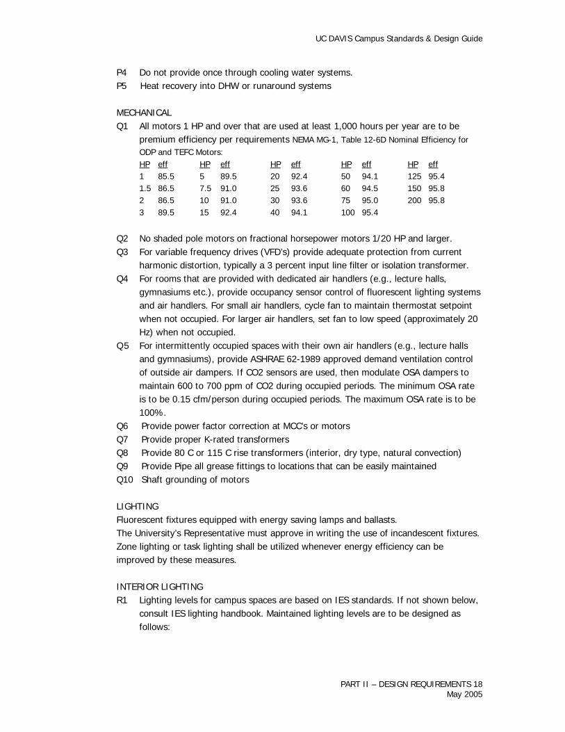
MECHANICAL Q1 All motors 1 HP and over that are used at least 1,000 hours per year are to be
premium efficiency per requirements NEMA MG-1, Table 12-6D Nominal Efficiency for ODP and TEFC Motors:
HP eff HP eff HP eff HP eff HP eff 1 85.5 5 89.5 20 92.4 50 94.1 125 95.4 1.5 86.5 7.5 91.0 25 93.6 60 94.5 150 95.8 2 86.5 10 91.0 30 93.6 75 95.0 200 95.8 3 89.5 15 92.4 40 94.1 100 95.4
Q2 No shaded pole motors on fractional horsepower motors 1/20 HP and larger. Q3 For variable frequency drives (VFD’s) provide adequate protection from current
harmonic distortion, typically a 3 percent input line filter or isolation transformer. Q4 For rooms that are provided with dedicated air handlers (e.g., lecture halls,
gymnasiums etc.), provide occupancy sensor control of fluorescent lighting systems and air handlers. For small air handlers, cycle fan to maintain thermostat setpoint when not occupied. For larger air handlers, set fan to low speed (approximately 20 Hz) when not occupied.
Q 5 For intermittently occupied spaces with their own air handlers (e.g., lecture halls and gymnasiums), provide ASHRAE 62-1989 approved demand ventilation control of outside air dampers. If CO2 sensors are used, then modulate OSA dampers to maintain 600 to 700 ppm of CO2 during occupied periods. The minimum OSA rate is to be 0.15 cfm/person during occupied periods. The maximum OSA rate is to be 100%.
Q6 Provide power factor correction at MCC’s or motors Q7 Provide proper K-rated transformers Q8 Provide 80 C or 115 C rise transformers (interior, dry type, natural convection) Q9 Provide Pipe all grease fittings to locations that can be easily maintained Q10 Shaft grounding of motors
LIGHTING Fluorescent fixtures equipped with energy saving lamps and ballasts. The University’s Representative must approve in writing the use of incandescent fixtures. Zone lighting or task lighting shall be utilized whenever energy efficiency can be improved by these measures.
INTERIOR LIGHTING R1 Lighting levels for campus spaces are based on IES standards. If not shown below,
consult IES lighting handbook. Maintained lighting levels are to be designed as follows:
PART II – DESIGN REQUIREMENTS 18 May 2005

UC DAVIS Campus Standards & Design Guide
Maintained Foot Candle Requirements Illumination Level Type of Occupancy in Foot-Candles Auditorium
Assembly Only ..................................................... 15 Study Hall ........................................................... 50
Classroom Space Regular classroom work........................................ 50 Drafting rooms (manual) ...................................... 100
Corridors (see also- Emergency) Office, Classroom Buildings Intersections ............... 10** 20 Student Housing .................................................. 10**
Dormitory Rooms Prolonged Study .................................................. 50 Lounge/Lobbies ................................................... 10 Kitchen (w/o task light) ........................................ 50 Kitchen (with task light)........................................ 30
Emergency Lighting Corridors ............................................................. 1 min, 3 ave, 10 max ** Stairwells ............................................................ 1 min, 3 ave, 10 max **
Gymnasiums Assembly ............................................................ 15 Recreation, Practice ............................................. 30** Exhibits, Matches ................................................. 50** Kitchen, Commercial............................................. 75
Laboratories General ............................................................... 65 Close Work (task lighting)..................................... 100
Lecture Rooms General ............................................................... 35 Special, Demonstration, Exhibit (task lighting) ........ 100 Chalkboards, Markerboards (task lighting).............. 100
Libraries Reading Rooms, Carrels........................................ 50 Stacks (active)..................................................... 20* Book Repair and Bindings ..................................... 50 Check in and out, catalogs, card files ..................... 50
Lounges Study (with task light) .......................................... 30 Study (w/o task light)........................................... 50 Non-Study........................................................... 20
Offices Designing, detailed drafting (task lighting) ............. 100 Accounting, bookkeeping, business machines ......... 50 General, reading, transcribing, filing, mail sorting ... 50
PART II – DESIGN REQUIREMENTS 19 May 2005

UC DAVIS Campus Standards & Design Guide
General (w/ task lighting and user coordination)..... 30 Computer Rooms (VDT’s) ..................................... 30 - 50 *** Conference Rooms............................................... 30
Recreation Basketball (regulation) ......................................... 50** Basketball (recreation) ......................................... 30** Restrooms........................................................... 15** Service Areas (Mechanical, Electrical Rooms).......... 20** Stairwells (see also- Emergency) ........................... 10** * vertical FC at a work plane height of 30" ** work plane height of 0" *** see IES standard RP-24
R2 All general lighting fixtures to include high efficacy F32T8 lamps and electronic
ballasts where applicable. Suggested minimum ballast product quality requirements are: • Ballast shall have a 3 year manufacturer’s warranty and shall have been on the
commercial market for a minimum of two years. • Ballast shall be UL listed class P and sound rated A. • Ballast must be instant start and parallel wired, solid state, not hybrid. • Ballast shall maintain light regulation of +/- 10 percent with +/- 10 percent
input voltage variation. • Current total harmonic distortion shall be less than 10 percent. • Flicker shall be 15 percent or less with any lamp suitable for the ballast. • Ballast shall be designed to withstand line transients per IEEE 587, category A. • Ballast shall meet FCC Rules and Regulations, Part 18. • Ballast shall operate at 20 kHz or greater.
R3 Specify 3500 kelvin for F32T8 lamp color. If color rendering is important consider specifying a minimum CRI of 80.
R4 Emergency EXIT signs are to be the LED type. Maximum wattage per sign shall be less than 7 watts and the minimum warranty shall be 5 years. Signs are to be painted white and use green LED’s.
R5 The use of standard incandescent lighting (e.g., A-lamps, R-40’s, PAR-38’s etc.) shall be minimized (including closets). If a high color rendering lamp or point source of light is necessary, consider the use of 130-volt halogen lamps. Wherever appropriate, the use of hard-wired compact fluorescent shall be maximized.
R6 In rooms where incandescent lighting and fluorescent lighting are provided for different uses, provide an interlock so that only one type of light source can be used at one time.
R7 Occupancy sensors are to be provided in all common bathrooms (2 water closets or more with connected load of 150 watts or more) lecture halls and classrooms. Specify ceiling mounted, ultrasonic type sensors. Locate sensors so that they will “see” inside bathroom stalls, but will not “see” outside the room. Provide standard wall switches in classrooms and in bathrooms that have windows so that the lights
PART II – DESIGN REQUIREMENTS 20 May 2005

UC DAVIS Campus Standards & Design Guide
may be turned off manually. Light switches are not required in bathrooms with no windows. In bathrooms, provide 1- PL fixture near door that is not controlled by the occupancy sensor but is controlled only by the switch.
R8 For buildings that utilize DDC for HVAC control, integrate the Title 24 required light sweeping system into the DDC controls system, where feasible.
R9 In enclosed stairwells, provide adequate day-lighting for emergency egress if possible and put any stairwell lighting on photocell control.
R10 Maximize use of 3 and 4 lamp ballasts R11 Wall mounted occupancy sensors in private offices R12 15 minute twist timer for bulletin board lighting R13 4 hour twist timer for janitor closets
EXTERIOR LIGHTING S1 In general, all exterior lighting is to be high-pressure sodium. Metal halide is
acceptable if good color rendition is necessary. Fluorescent or compact fluorescent is acceptable for small areas.
S2 Provide two switched conductors to each exterior fixture. One switched conductor is to be on a timeclock, (dusk to 11 PM), the other switched conductor is to be on photocell (dusk to dawn) or astronomic clock. Conductors should be located such that any fixture can be changed from one conductor to the other with minimal effort.
EMERGENCY POWER T1 Design system for load shedding capabilities T2 Autostart and transfer generator using EMCS system T3 Emergency generator alarms shall be interfaced with the campus remote monitoring system.
PART II – DESIGN REQUIREMENTS 21 May 2005