general applications 1 e 01-12 -...
TRANSCRIPT

GENERAL APPLICATIONS E 01-121
HYDRAULIC ACCUMULATORS 1.1
APPLICATION FIELDS 1.2
APPLICATIONS 1.3
CERTIFICATIONS 1.4
ELASTOMERS 1.5
EPE ITALIANA s.r.l. - Viale Spagna,112 • 20093 Cologno Monzese (Mi) Italy Tel.: +39 02 25459028 • Fax: +39 02 25 25459773 • E-mail: [email protected] • Internet: www.epeitaliana.it


HYDRAULIC ACCUMULATORS E 01-121.1
EPE ITALIANA s.r.l. - Viale Spagna,112 • 20093 Cologno Monzese (Mi) Italy Tel.: +39 02 25459028 • Fax: +39 02 25 25459773 • E-mail: [email protected] • Internet: www.epeitaliana.it
1.1.1 GENERALThe main task of the hydraulic accumulator is to accumulate fluid underpressure and return it when necessary. Since the accumulator contains a fluid under pressure, it is treated as apressure tank and must therefore be sized for the maximum operating pres-sure according to test regulations in force in the country where it is instal-led. To achieve the volume compensation and get the accumulation of energy,the fluid is pre-loaded by a weight, a spring or a compressed gas.
Between the pressure of fluid and the counter-pressure exerted by theweight, the spring or the compressed gas must be in a constant state ofequilibrium. Weight and spring accumulators are used in industry only inspecial cases and thus have a relative importance.Gas accumulators without a separating element are rarely used in hy-draulics due to the absorption of gas by the fluid. In most of the hydraulic systems are then used the gas accumulatorsprovided with a separating element between gas and fluid.Depending on the type of separating element, we can distinguish blad-der, piston and diaphragm accumulators.
1.1.2 TYPES OF ACCUMULATORS WITH SEPARATING ELEMENT
These accumulators consist of a fluid zone, a gas zone and a separatinggas-tight element. The fluid area is in contact with the circuit. With the pressure increases,a certain volume of fluid enters into the accumulator and compressesthe gases. In the hydraulic systems, are used with the following accumulators witha separating element:- bladder accumulators (Fig. 1.1b)- piston accumulators (Fig. 1.1c)- diaphragm accumulators (Fig. 1.1d)
1.1.2.1 BLADDER ACCUMULATORSIn the bladder accumulators, the fluid area is separated from the gasarea by a flexible bladder. The fluid around the bladder is in contact withthe circuit, so any increase in pressure causes the entry of the fluid intothe accumulator and thereby compresses the gas. Vice versa, every dropof pressure in the circuit causes the expansion of the gas, resulting in de-livery of the fluid from the accumulator to the circuit. Bladder accumulators can be installed in vertical position (preferable),in horizontal one and, under certain operating conditions, also in an in-clined one. In the inclined and vertical positions, the valve on the fluid sideshould face down. The bladder accumulators include a pressure weldedor forged vessel, a flexible bladder and the fittings for gas and oil.
1.1.2.2 PISTON ACCUMULATORSIn the piston accumulators, the fluid area is separated from the gasarea from a metal piston fitted with gas tight seals. The gas area is fil-led with nitrogen. The fluid zone is connected to the hydraulic system, so any increase
1
Precharge valve
Shell
Bladder
Poppet valve
Bleed
Fluid port valve Gas
Precharge valve
End cap gas side
Cilinder
Piston
Seals
End cap oil side
Fluid connection Gas
1.1c
1.1a
1.1b

EPE ITALIANA s.r.l. - Viale Spagna,112 • 20093 Cologno Monzese (Mi) Italy Tel.: +39 02 25459028 • Fax: +39 02 25 25459773 • E-mail: [email protected] • Internet: www.epeitaliana.it
HYDRAULIC ACCUMULATORSE 01-121.1
in pressure in the circuit causes the entry of fluid in the accumulatorresulting in compression of the gas. Vice versa, at every drop of pressure in the circuit, the compressedgas contained in the accumulator expands and the accumulator deli-vers the fluid to circuit. The piston accumulators can operate in any position, but it is prefera-ble to mount them with the gas area upwards in order to prevent thatsolid contaminants contained in the fluid settle by gravity on the pi-ston seals. The typical structure of the piston accumulator, represented schema-tically in Figure 1.1c, includes a cylindrical pipe, a piston with seals,end caps in which there are the fluid side and gas side connections. The pipe serves to resist to the internal pressure and to drive the pi-ston. To ensure that the pressures of the two chambers are as balanced aspossible, during the movement, it's necessary that the friction betweenthe piston and the pipe is minimized.For this reason, the inner surface of the pipe must be honed. In prac-tice, however, the friction between the piston seals and the pipe crea-tes, between gas area and fluid one, a pressure difference that,however, can be limited to 1 bar with appropriate selection of seals.The position of the piston can be shown continuously through a pas-sing rod. By fixing a cam to the rod, you can also take advantage ofthe movement of the piston in order to control through limit switchesthe switching on or switching off of the pump.For other types of monitoring of the piston position, see Section 4.1.
1.1.2.3 DIAPHRAGM ACCUMULATORSDiaphragm accumulators are made of a steel pressure-resistant vessel,usually cylindrical or spherical in shape, inside which is mounted a flexi-ble material diaphragm as separating element. Diaphragm accumulators are manufactured in three versions: - screwed execution (see Section 5.1.)- forged execution (see Section 5.2.) - welded execution (see Section 5.3.)
In the screwed version, the diaphragm is blocked by a metal ring fittedbetween the lower shell and upper shell of the body. In the welded accumulators, the diaphragm is pressed into the bottom be-fore the welding of two steel shells. Thanks to appropriate processes such as electron beam welding andalso thanks to the special provision of the diaphragm, it's possible to pre-vent its damage and forging.
1.1.2.4 DERIVATION CONNECTION OF THE GAS BOTTLES
When for a given volume of fluid to provide/absorb the difference bet-ween the maximum and minimum pressure in the hydraulic circuit mustbe of limited size, the volume of the accumulator, obtainable with the cal-culation, may be very large. Under these conditions, it is preferable toconnect the gas side of the accumulator with one or more additional gasbottles (Fig. 1.1l). For the sizing of the accumulator, you should take intoaccount the following parameters: - the useful volume to provide/absorb - allowable ratios of pressures and volumes P2/Po = V0/V2 - the expansion of gas volume due to changes in operating temperature.
1.1.3 OPERATING CONDITIONSStage AThe accumulator is empty and neither gas nor hydraulic sides are pres-surized Po = P = 0 bar
Stage BThe accumulator is pre-charged Po
Stage CThe hydraulic system is pressurized. System pressure exceeds the pre-charge one and the fluid flows into the accumulator Po→P1
Stage DSystem pressure peaks. The accumulator is filled with fluid according to its design capacity. Any further increase in hydraulic pressure would be prevented by a re-lief valve fitted on the system P1→P2
Stage ESystem pressure falls. Pre-charge pressure forces the fluid from the ac-cumulator into the system P2→P1
Stage FMinimum system pressure is reached. The accumulator has dischar-ged its maximum design volume of fluid back into the system min ∆P(P1min)
2
Precharge valve
Gas
ShellDiaphragm
Button
Fluid connection
1.1d

1.1.4.1 FAILURE MODESIn certain applications, a sudden failure may be preferable than a gra-dual failure. A high-speed machine, for example, where product qua-lity is a function of hydraulic system pressure.As sudden failure is detected immediately, scrap is minimized, whe-reas a gradual failure might mean that production of a large quantityof sub-standard product could occur before the failure becomes appa-rent. A bladder/diaphragm accumulator would be most suitable to this ap-plication. Vice versa, where continuous operation is paramount andsudden failure could be detrimental as, for example, in a braking orsteering circuit on mobile equipment, a progressive failure mode isdesirable. In this application, a piston accumulator would be appro-priate.
1.1.4.2 FLOW RATEFig. 1.1.n shows typical maximum flow rates for Epe’s accumulator sty-les in a range of sizes.The larger standard bladder designs are limited to 1000 LPM, althoughthis may be increased to 2000 LPM using a high-flow port. The poppet valve controls the flow rate, with excessive flow causing the
HYDRAULIC ACCUMULATORS E 01-121.1
EPE ITALIANA s.r.l. - Viale Spagna,112 • 20093 Cologno Monzese (Mi) Italy Tel.: +39 02 25459028 • Fax: +39 02 25 25459773 • E-mail: [email protected] • Internet: www.epeitaliana.it
1.1.4 ACCUMULATOR SELECTIONSWhen selecting an accumulator for a particular application, both sy-stem and performance criteria should be taken into account. To ensure long and satisfactory service life, the following factors shouldbe taken into account.
- failure modes- flow rate- response time- high frequency cycling- external forces- output volume- fluid type- shock suppression- sizing information- temperature effect- safety- certification
3
Gas
Stage A Stage B Stage C Stage D Stage E Stage F
1.1e

Fig. 1.1f: Perpendicular force causes the mass of the fluid to displacethe bladder. Higher pre-charge pressures increase the resistance of thebladder according to the effects of the perpendicular forces.
1.1.4.6 OUTPUT VOLUMEThe maximum sizes available of each type of accumulator determine thelimits of suitability where large output volumes are required. There are,however, several methods to achieve higher output volumes than standardaccumulator capacities suggest - see Accumulators station, Section 10.
Fig. 1.1g compares typical fluid outputs for Epe’s 35 litres piston andbladder accumulators operating isothermally as auxiliary power sour-ces over a range of minimum system pressures. The higher pre-charge pressures recommended for piston accumula-tors result in higher outputs than as occurred in comparable bladder ac-cumulators.
EPE ITALIANA s.r.l. - Viale Spagna,112 • 20093 Cologno Monzese (Mi) Italy Tel.: +39 02 25459028 • Fax: +39 02 25 25459773 • E-mail: [email protected] • Internet: www.epeitaliana.it
HYDRAULIC ACCUMULATORSE 01-121.1
poppet to close prematurely.Flow rates greater than 2000 LPM may be achieved by mounting several ac-cumulators on a common manifold - see Accumulators station, Section 10.For a given system pressure, flow rates for piston accumulators gene-rally exceed those of the bladder designs. Flow is limited by piston velocity, which should not exceed 3 m/sec. toavoid piston seal damage. In high-speed applications, high seal contact temperatures and rapiddecompression of nitrogen, which has permeated the seal itself, cancause blisters, cracks and pits in the seal surface. In this type of appli-cation, a bladder style accumulator would be better suited.
1.1.4.3 RESPONSE TIMEIn theory, bladder and diaphragm accumulators should respond morequickly to system pressure variations than piston types. There is no static friction to be overcome as occurs with a piston seal,and there is no piston mass to be accelerated and decelerated. In practice, however, the difference in response is not great, and is pro-bably insignificant in most applications.This applies equally in servo applications, as only a small percentageof servos requires response times of 25 ms or less. This is the point where the difference in response between piston andbladder accumulators becomes significant. Generally, a bladder accumulator should be used for applications requi-ring less than 25 ms response time, and either accumulator type for aresponse of 25 ms or greater.
1.1.4.4 HIGH FREQUENCY CYCLINGHigh-frequency system pressure cycling can cause a piston accumula-tor to “dither”, with the piston cycling rapidly back and forth so coveringa distance less than its seal width.Over an extended period, this condition may cause heat build-up underthe seal due to lack of lubrication, resulting in seal and bore wear. For high frequency dampening applications, therefore, a bladder/dia-phragm accumulator is generally more suitable.
1.1.4.5 EXTERNAL FORCESAny application subjecting an accumulator to acceleration, decelerationor centrifugal force may have a detrimental effect on its operation, andcould cause damage to the bladder. Forces along the axis of the pipe or shell normally have little effect on abladder accumulator but may cause a variation in gas pressure in a pi-ston type accumulator because of the mass of the piston.Forces perpendicular to an accumulator’s axis should not affect a pistonmodel, but fluid in a bladder accumulator may be thrown to one side ofthe shell (Fig. 1.1f), displacing the bladder and flattening and lengthe-ning it. In this condition, fluid discharge could cause the poppet valve topinch and cut the bladder.
4
Force
1.1f
1.1g
Compres-sionratio
System
pressure bar
Recommended
Precharge bar
Fluid
Output LPM
max min Bladder Piston Bladder Piston
1,5 210 140 125 130 10,5 11,5
2 210 105 95 98 16 16,5
3 210 70 60 60 21,5 21,5
6 210 35 * 28 * 24
* Below required minimum operating ratio of 4:1

In addition, bladder accumulators are not generally suitable for com-pression ratios greater than 1:4, as these could result in excessivebladder deformation.Piston accumulators have an inherently higher output relative to theiroverall dimensions, which may be critical in locations where space islimited. Piston accumulators are available in a choice of diameters and lengthsfor a given capacity, whereas bladder and diaphragm accumulators arefrequently offered in only one size per capacity, and fewer sizes areavailable. Piston accumulators can also be built to custom lengths for applica-tions in which the available space is critical
1.1.4.7 FLUID TYPEBladder/Diaphragm accumulators are more resistant to damage cau-sed by contamination of the hydraulic fluid than piston types. While some risks exist from contaminants trapped between the blad-der and the shell, a higher risk of failure exists from the same conta-minants acting on the piston seal.Bladder accumulators are usually preferred to piston type accumulatorsfor water service applications. Water systems tend to carry more solid contaminants and lubricationis poor. Both the piston and bladder type units require some type of prepara-tion to resist to corrosion on the wetted surfaces (example nickel coa-ted) Piston accumulators are preferred for systems using specialfluids or where extreme temperatures are experienced as comparedto bladders. Piston seals are more easily moulded in the required special com-pounds and may be less expensive.
1.1.4.8 SHOCK SUPPRESSIONShock control does not necessarily demand a bladder/diaphragm accumu-lator, it is possible to use also a piston accumulator, see example Fig. 1.1h
HYDRAULIC ACCUMULATORS E 01-121.1
EPE ITALIANA s.r.l. - Viale Spagna,112 • 20093 Cologno Monzese (Mi) Italy Tel.: +39 02 25459028 • Fax: +39 02 25 25459773 • E-mail: [email protected] • Internet: www.epeitaliana.it
5
280
140
0
Pres
sure
– b
ar
000200010Time – ms
No accumulator in circuit
Piston accumulator
Bladder accumulator
1.1h
1.1.4.9 MOUNTING POSITIONThe optimum mounting position for any accumulator is vertical, with thehydraulic port downwards. Piston models can be mounted horizontally ifthe fluid is kept clean but, if solid contaminants are present or expectedin significant amount; horizontal mounting can result in uneven or acce-lerated seal wear.A bladder accumulator may also be mounted horizontally, but unevenwear on the top of the bladder as it rubs against the shell while floatingone the fluid can reduce its service life and even cause permanent distor-tion. The extent of the damage will depend on the fluid cleanliness, cycle rate,and compression ratio. In extreme cases, fluid can be trapped away fromthe hydraulic port ( Fig. 1.1i),
Fig. 1.1i A horizontally-mounted bladder accumulator can trap fluid awayfrom the hydraulic valve reducing output, or the bladder may becomeelongated, forcing the poppet valve to close prematurely.
1.1.4.10 SIZING INFORMATIONAccurate sizing of an accumulator is critical if it has to deliver a long andreliable service life. Information and worked examples are shown in Sec-tion 2 or accumulator size can be calculated automatically by entering ap-plication details into Epe’s Sizing software selection program. Please contact your local Epe distributor for details or contact us atwww.epeitaliana.it
1.1.4.11 TEMPERATURE EFFECTTemperature variation can seriously affect the pre-charge pressure of anaccumulator. As the temperature increases, the pre-charge pressure in-creases; Vice versa, decreasing temperature will decrease the pre-charge pressure. In order to assure the accuracy of your accumulatorpre-charge pressure, you need to factor in the temperature variation. The temperature variation is determined by the temperature encounte-red during the pre-charge versus the operating temperature expected inthe system, (see Section 2.2.)
1.1.4.12 SAFETYHydro-pneumatic accumulators should always be used in conjunctionwith a safety block, to enable the accumulator to be isolated from the cir-cuit in an emergency or for maintenance purposes, (see Section8 e 9).
1.1.4.13 CERTIFICATIONAccumulators are frequently required to conform to national or interna-tional certification. These requirements range from simple design factorsto elaborate materials testing and inspection procedures carried out byan external agency. Most of the accumulators within Epe’s piston, blad-der or diaphragm ranges are available with certification PED97/23EC orother on request (see Section 1.4)
1.1i
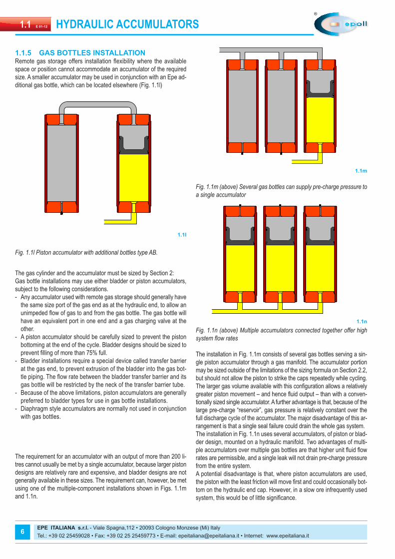
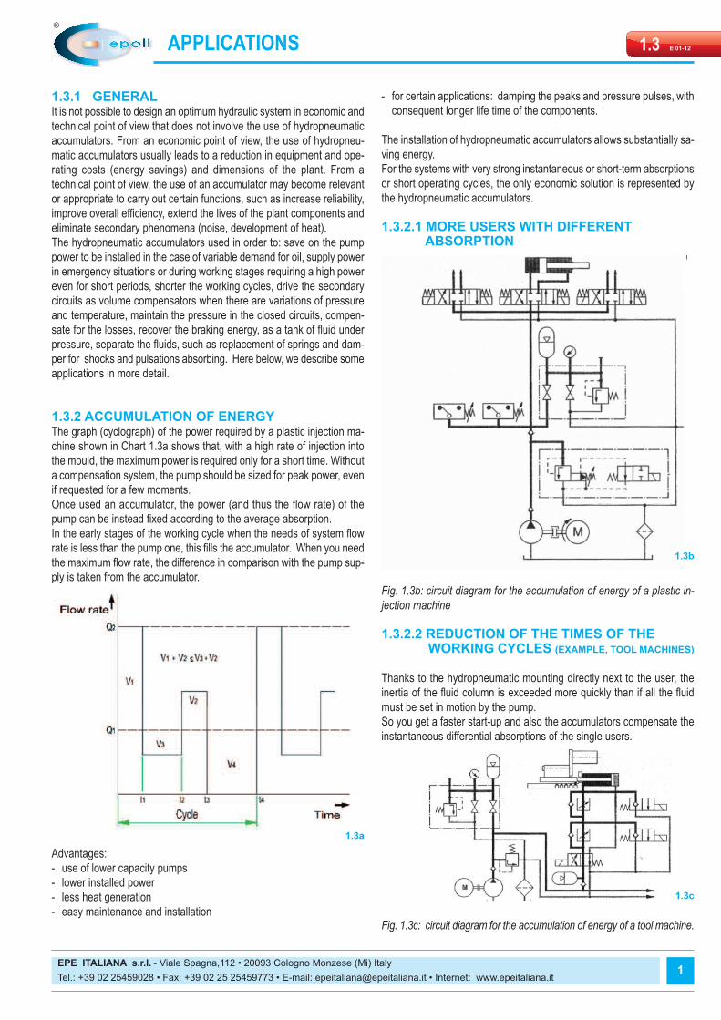
Fig. 1.1m (above) Several gas bottles can supply pre-charge pressure toa single accumulator
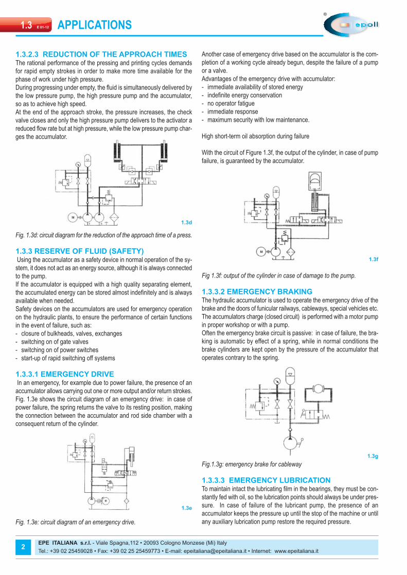
Fig. 1.1n (above) Multiple accumulators connected together offer highsystem flow rates
The installation in Fig. 1.1m consists of several gas bottles serving a sin-gle piston accumulator through a gas manifold. The accumulator portionmay be sized outside of the limitations of the sizing formula on Section 2.2,but should not allow the piston to strike the caps repeatedly while cycling.The larger gas volume available with this configuration allows a relativelygreater piston movement – and hence fluid output – than with a conven-tionally sized single accumulator. A further advantage is that, because of thelarge pre-charge “reservoir”, gas pressure is relatively constant over thefull discharge cycle of the accumulator. The major disadvantage of this ar-rangement is that a single seal failure could drain the whole gas system.The installation in Fig. 1.1n uses several accumulators, of piston or blad-der design, mounted on a hydraulic manifold. Two advantages of multi-ple accumulators over multiple gas bottles are that higher unit fluid flowrates are permissible, and a single leak will not drain pre-charge pressurefrom the entire system.A potential disadvantage is that, where piston accumulators are used,the piston with the least friction will move first and could occasionally bot-tom on the hydraulic end cap. However, in a slow ore infrequently usedsystem, this would be of little significance.
EPE ITALIANA s.r.l. - Viale Spagna,112 • 20093 Cologno Monzese (Mi) Italy Tel.: +39 02 25459028 • Fax: +39 02 25 25459773 • E-mail: [email protected] • Internet: www.epeitaliana.it
HYDRAULIC ACCUMULATORSE 01-121.1
1.1.5 GAS BOTTLES INSTALLATIONRemote gas storage offers installation flexibility where the availablespace or position cannot accommodate an accumulator of the requiredsize. A smaller accumulator may be used in conjunction with an Epe ad-ditional gas bottle, which can be located elsewhere (Fig. 1.1l)
Fig. 1.1l Piston accumulator with additional bottles type AB.
The gas cylinder and the accumulator must be sized by Section 2:Gas bottle installations may use either bladder or piston accumulators,subject to the following considerations.- Any accumulator used with remote gas storage should generally have
the same size port of the gas end as at the hydraulic end, to allow anunimpeded flow of gas to and from the gas bottle. The gas bottle willhave an equivalent port in one end and a gas charging valve at theother.
- A piston accumulator should be carefully sized to prevent the pistonbottoming at the end of the cycle. Bladder designs should be sized toprevent filling of more than 75% full.
- Bladder installations require a special device called transfer barrierat the gas end, to prevent extrusion of the bladder into the gas bot-tle piping. The flow rate between the bladder transfer barrier and itsgas bottle will be restricted by the neck of the transfer barrier tube.
- Because of the above limitations, piston accumulators are generallypreferred to bladder types for use in gas bottle installations.
- Diaphragm style accumulators are normally not used in conjunctionwith gas bottles.
The requirement for an accumulator with an output of more than 200 li-tres cannot usually be met by a single accumulator, because larger pistondesigns are relatively rare and expensive, and bladder designs are notgenerally available in these sizes. The requirement can, however, be metusing one of the multiple-component installations shown in Figs. 1.1mand 1.1n.
6
1.1l
1.1m
1.1n

HYDRAULIC ACCUMULATORS E 01-121.1
EPE ITALIANA s.r.l. - Viale Spagna,112 • 20093 Cologno Monzese (Mi) Italy Tel.: +39 02 25459028 • Fax: +39 02 25 25459773 • E-mail: [email protected] • Internet: www.epeitaliana.it
1.1.6 FAILURE PREVENTIONAccumulator failure is generally defined as inability to accept and exhausta specified amount of fluid when operating over a specific system pres-sure range.Failure often results from an unwanted loss or gain of pre-charge pres-sure.It cannot be too highly stressed that the correct pre-charge pressure isthe most important factor in prolonging accumulator life.If maintenance of the pre-charge pressure and relief valve settings areneglected, and if system pressures are adjusted without making corresponding adjustments to pre-charge pressures, shortened servicelife will result.
1.1.6.1 FAILUREBladder/diaphragm accumulator failure occurs rapidly due to bladder/dia-phragm rupture (Fig. 1.1o). Rupture cannot be predicted because the in-tact bladder or diaphragm is essentially impervious to gas of fluidseepage; no measurable gas or fluid leakage through the bladder or dia-phragm precedes failure.
1.1.6.2 PISTON ACCUMULATOR FAILUREPiston Accumulator failure generally occurs in one of the following gra-dual modes.
- FLUID LEAKS TO THE GAS SIDEThis failure, sometimes called dynamic transfer, normally takes place du-ring rapid cycling operations after considerable time in service. The wornpiston seal carries a small amount of fluid into the gas side during eachstroke.As the gas side slowly fills with fluid, pre-charge pressure rises and theaccumulator stores and exhausts decreasing the amounts of fluid. Theaccumulator will totally fail when pre-charge pressure equals the maxi-mum hydraulic system pressure. At that point, the accumulator will acceptno further fluid. As the increase in pre-charge pressure can be measu-red (Fig. 1.1oa), failure can be predicted and repairs can be carried outbefore total failure occurs.
- GAS LEAKAGEPre-charge may be lost as gas slowly bypasses the damaged pistonseals. Seal deterioration occurs due to excessively long service, fluidcontamination or a combination of the two. Gas can also vent directlythrough a defective gas core or an end cap O-ring.The reducing pre-charge pressure then forces progressively less fluidinto the system. As this gradual decrease in pre-charge pressure can bemeasured (Fig. 1.1ob), repairs can again be carried out before total fai-lure occurs.
7
Fig.1.1.o When anaccumulatorbladder ruptures,precharge pres-sure immediatelyfalls to zero
As �uid leaks pastan accumulatorpiston, prechargepressure rises (oa).
Prec
harg
epr
essu
re –
bar
Number of cycles
Prec
harg
epr
essu
re –
bar
Number of cycles (oa)
Prec
harg
epr
essu
re –
bar
Number of cycles (ob)
Gas leaking pastthe piston or valvecauses prechargepressure to fall (ob)
1.1o
1.1.7 PRE-CHARGING PROCESSCorrect pre-charging involves accurately filling of the gas side of an ac-cumulator with a dry, inert gas such as nitrogen, before admitting fluid tothe hydraulic side.It is important to pre-charge an accumulator under the correct specifiedpressure. Pre-charge pressure determines the volume of fluid retained inthe accumulator at minimum system pressure. In an energy storage ap-plication, a bladder/ diaphragm accumulator is typically pre-charged to90% of the minimum system pressure, and a piston accumulator to 97%of the minimum system pressure at the system operating temperature.The ability to correctly carry out and maintain pre-charging is an impor-tant factor when choosing the type of accumulator for an application.Bladder accumulators are more susceptible to damage during pre-char-ging than piston types. Before pre-charging and entering in service, theinside of the shell should be lubricated with system fluid.This fluid acts as a cushion and lubricates and protects the bladder as itexpands. When pre-charging, the first 10 bar of nitrogen should be intro-duced slowly. Failure to follow this precaution could result in immediatebladder failure: high pressure nitrogen, expanding rapidly and thus cold,could form a channel in the folded bladder, concentrating at the bottom.The chilled expanding rapidly brittle rubber would then inevitably causethe rupture (Fig. 1.1p).The bladder could also be forced under the poppet, resulting in a cut.(Fig. 1.1q).Close attention should be paid to operating temperature during pre-char-ging, as an increase in temperature will cause a corresponding increasein pressure which could then exceed the pre-charge limit.Little damage can occur when pre-charging or checking the pre-chargeon a piston accumulator, but care should be taken to make sure the ac-cumulator is void of all fluid to prevent getting an incorrect reading onthe pre-charge.

EPE ITALIANA s.r.l. - Viale Spagna,112 • 20093 Cologno Monzese (Mi) Italy Tel.: +39 02 25459028 • Fax: +39 02 25 25459773 • E-mail: [email protected] • Internet: www.epeitaliana.it
HYDRAULIC ACCUMULATORSE 01-121.1
Fig. 1.1p Starburst rupture caused by loss of bladder elasticity
Fig. 1.1q C-shaped cut shows that bladder has been trapped under pop-pet
EXCESSIVELY HIGH PRE-CHARGEExcessive pre-charge pressure or a decrease in the minimum systempressure without a corresponding reduction in pre-charge pressure maycause operating problems or damage to accumulators.With excessive pre-charge pressure, a piston accumulator will cyclebetween stages (e) and (b) of Fig. 1.1e), and the piston will travel tooclose to the hydraulic end cap. The piston could bottom at minimum sy-stem pressure, thus reducing the output and eventually damaging thepiston and the piston seal. The piston can often be heard bottoming, war-ning of impending problems.An excessive pre-charge in a bladder accumulator can drive the bladderinto the poppet assembly when cycling between stages (e) and (b).Thiscould cause fatigue failure of the poppet spring assembly, or even a pin-ched and cut bladder, should it become trapped beneath the poppet asit is forced closed (Fig. 1.1q). Excessive pre-charge pressure is the mostcommon cause of bladder failure.
8
Reproduction is forbidden.In the spirit of continuous improvement, our products may be changed.
1.1p
1.1q
EXCESSIVELY LOW PRE-CHARGEExcessively low pre-charge pressure or an increase in system pressurewithout a corresponding increase in pre-charge pressure can also causeoperating problems and subsequent accumulator damage. With no pre-charge in a piston accumulator, the piston will be driven into the gas endcap and will often remain there. Usually, a single contact will not causeany damage, but repeated impacts will eventually damage the piston andseal.Vice versa, for a bladder accumulator, too low or no pre-charge can haverapid and severe consequences. The bladder will be crushed into the topof the shell and can extrude into the gas stem and be punctured (Fig1.1r). This condition is known as “pick out”. One cycle as the one men-tioned above is sufficient to destroy a bladder.Overall, piston accumulators are generally more tolerant with respect tocareless pre-charging.
1.1r

APPLICATION FIELDS E 01-121.2
EPE ITALIANA s.r.l. - Viale Spagna,112 • 20093 Cologno Monzese (Mi) Italy Tel.: +39 02 25459028 • Fax: +39 02 25 25459773 • E-mail: [email protected] • Internet: www.epeitaliana.it
1.2.1 DESCRIPTIONThe main sectors and areas of application are industrial hydraulics, pro-cess technology and mobile sistems
1.2.2 ENERGY POWER PLANTSEnergy is the topic of the future. Global energy demand is rapidly rising.Oil supply for lubrication and/or emergency.
1.2.3 DIE CASTING MACHINERYHigh pressure and flows in a short time period.
1.2.4 PLASTIC MACHINERYQuick response.
1.2.5 STEEL INDUSTRYHigh pressure and fast movements.
1
1.2a
1.2b
1.2c 1.2f
1.2e
1.2d

1.2.6 MACHINE TOOLSMaintains pressure, reduces pump size.
1.2.7 CRANES VEHICLESHigh demands and load stabilizer.
1.2.8 CHEMICAL INDUSTRYReduce pump pulsations.
1.2.9 CONSTRUCTION MOBILE MACHINERYConstant power.
EPE ITALIANA s.r.l. - Viale Spagna,112 • 20093 Cologno Monzese (Mi) Italy Tel.: +39 02 25459028 • Fax: +39 02 25 25459773 • E-mail: [email protected] • Internet: www.epeitaliana.it
APPLICATION FIELDSE 01-121.2
2
1.2l1.2h
1.2g 1.2i

APPLICATION FIELDS E 01-121.2
EPE ITALIANA s.r.l. - Viale Spagna,112 • 20093 Cologno Monzese (Mi) Italy Tel.: +39 02 25459028 • Fax: +39 02 25 25459773 • E-mail: [email protected] • Internet: www.epeitaliana.it
1.2.10 OIL & GAS / OFFSHOREEmergency and shock damper.
1.2.11 INDUSTRIAL APPLICATIONSEnergy reserve.
1.2.12 AUTOMOTIVEBraking system.
3
1.2n
1.2o
1.2o1.2m
1.2p
1.2p

EPE ITALIANA s.r.l. - Viale Spagna,112 • 20093 Cologno Monzese (Mi) Italy Tel.: +39 02 25459028 • Fax: +39 02 25 25459773 • E-mail: [email protected] • Internet: www.epeitaliana.it
APPLICATION FIELDSE 01-121.2
1.2.14 AGRICULTURY MACHINERYStabilizer system.
4
Reproduction is forbidden.In the spirit of continuous improvement, our products may be changed.
1.2.13 LOADING STATIONShock absorber.
1.2q
1.2r
1.2s
1.2.15 COMPENSATORLiquid separator and pressure compensator for subsea applications.
APPLICATIONS E 01-121.3
EPE ITALIANA s.r.l. - Viale Spagna,112 • 20093 Cologno Monzese (Mi) Italy Tel.: +39 02 25459028 • Fax: +39 02 25 25459773 • E-mail: [email protected] • Internet: www.epeitaliana.it
1.3.1 GENERALIt is not possible to design an optimum hydraulic system in economic andtechnical point of view that does not involve the use of hydropneumaticaccumulators. From an economic point of view, the use of hydropneu-matic accumulators usually leads to a reduction in equipment and ope-rating costs (energy savings) and dimensions of the plant. From atechnical point of view, the use of an accumulator may become relevantor appropriate to carry out certain functions, such as increase reliability,improve overall efficiency, extend the lives of the plant components andeliminate secondary phenomena (noise, development of heat). The hydropneumatic accumulators used in order to: save on the pumppower to be installed in the case of variable demand for oil, supply powerin emergency situations or during working stages requiring a high powereven for short periods, shorter the working cycles, drive the secondarycircuits as volume compensators when there are variations of pressureand temperature, maintain the pressure in the closed circuits, compen-sate for the losses, recover the braking energy, as a tank of fluid underpressure, separate the fluids, such as replacement of springs and dam-per for shocks and pulsations absorbing. Here below, we describe someapplications in more detail.
1.3.2 ACCUMULATION OF ENERGYThe graph (cyclograph) of the power required by a plastic injection ma-chine shown in Chart 1.3a shows that, with a high rate of injection intothe mould, the maximum power is required only for a short time. Withouta compensation system, the pump should be sized for peak power, evenif requested for a few moments.Once used an accumulator, the power (and thus the flow rate) of thepump can be instead fixed according to the average absorption. In the early stages of the working cycle when the needs of system flowrate is less than the pump one, this fills the accumulator. When you needthe maximum flow rate, the difference in comparison with the pump sup-ply is taken from the accumulator.
Advantages: - use of lower capacity pumps - lower installed power - less heat generation - easy maintenance and installation
- for certain applications: damping the peaks and pressure pulses, withconsequent longer life time of the components.
The installation of hydropneumatic accumulators allows substantially sa-ving energy. For the systems with very strong instantaneous or short-term absorptionsor short operating cycles, the only economic solution is represented bythe hydropneumatic accumulators.
1.3.2.1 MORE USERS WITH DIFFERENT ABSORPTION
Fig. 1.3b: circuit diagram for the accumulation of energy of a plastic in-jection machine
1.3.2.2 REDUCTION OF THE TIMES OF THEWORKING CYCLES (EXAMPLE, TOOL MACHINES)
Thanks to the hydropneumatic mounting directly next to the user, theinertia of the fluid column is exceeded more quickly than if all the fluidmust be set in motion by the pump. So you get a faster start-up and also the accumulators compensate theinstantaneous differential absorptions of the single users.
Fig. 1.3c: circuit diagram for the accumulation of energy of a tool machine.
1
1.3a
1.3b
1.3c
EPE ITALIANA s.r.l. - Viale Spagna,112 • 20093 Cologno Monzese (Mi) Italy Tel.: +39 02 25459028 • Fax: +39 02 25 25459773 • E-mail: [email protected] • Internet: www.epeitaliana.it
APPLICATIONSE 01-121.3
1.3.2.3 REDUCTION OF THE APPROACH TIMESThe rational performance of the pressing and printing cycles demandsfor rapid empty strokes in order to make more time available for thephase of work under high pressure. During progressing under empty, the fluid is simultaneously delivered bythe low pressure pump, the high pressure pump and the accumulator,so as to achieve high speed. At the end of the approach stroke, the pressure increases, the checkvalve closes and only the high pressure pump delivers to the activator areduced flow rate but at high pressure, while the low pressure pump char-ges the accumulator.
Fig. 1.3d: circuit diagram for the reduction of the approach time of a press.
1.3.3 RESERVE OF FLUID (SAFETY)Using the accumulator as a safety device in normal operation of the sy-stem, it does not act as an energy source, although it is always connectedto the pump. If the accumulator is equipped with a high quality separating element,the accumulated energy can be stored almost indefinitely and is alwaysavailable when needed. Safety devices on the accumulators are used for emergency operationon the hydraulic plants, to ensure the performance of certain functionsin the event of failure, such as: - closure of bulkheads, valves, exchanges- switching on of gate valves - switching on of power switches- start-up of rapid switching off systems
1.3.3.1 EMERGENCY DRIVEIn an emergency, for example due to power failure, the presence of anaccumulator allows carrying out one or more output and/or return strokes.Fig. 1.3e shows the circuit diagram of an emergency drive: in case ofpower failure, the spring returns the valve to its resting position, makingthe connection between the accumulator and rod side chamber with aconsequent return of the cylinder.
Fig. 1.3e: circuit diagram of an emergency drive.
Another case of emergency drive based on the accumulator is the com-pletion of a working cycle already begun, despite the failure of a pumpor a valve. Advantages of the emergency drive with accumulator: - immediate availability of stored energy - indefinite energy conservation - no operator fatigue - immediate response - maximum security with low maintenance.
High short-term oil absorption during failure
With the circuit of Figure 1.3f, the output of the cylinder, in case of pumpfailure, is guaranteed by the accumulator.
Fig 1.3f: output of the cylinder in case of damage to the pump.
1.3.3.2 EMERGENCY BRAKINGThe hydraulic accumulator is used to operate the emergency drive of thebrake and the doors of funicular railways, cableways, special vehicles etc.The accumulators charge (closed circuit) is performed with a motor pumpin proper workshop or with a pump. Often the emergency brake circuit is passive: in case of failure, the bra-king is automatic by effect of a spring, while in normal conditions thebrake cylinders are kept open by the pressure of the accumulator thatoperates contrary to the spring.
Fig.1.3g: emergency brake for cableway
1.3.3.3 EMERGENCY LUBRICATION To maintain intact the lubricating film in the bearings, they must be con-stantly fed with oil, so the lubrication points should always be under pres-sure. In case of failure of the lubricant pump, the presence of anaccumulator keeps the pressure up until the stop of the machine or untilany auxiliary lubrication pump restore the required pressure.
2
1.3d
1.3f
1.3g
1.3e

APPLICATIONS E 01-121.3
EPE ITALIANA s.r.l. - Viale Spagna,112 • 20093 Cologno Monzese (Mi) Italy Tel.: +39 02 25459028 • Fax: +39 02 25 25459773 • E-mail: [email protected] • Internet: www.epeitaliana.it
1.3.5 COMPENSATION OF LEAKAGES The compression force exerted by a hydraulic cylinder can only be main-tained by compensating the inevitable losses due to system leakage. The accumulators are particularly suitable for this purpose. Fig. 1.3mshows a scheme of a system of compensation for a leak, through which,when the pump is stopped, the leakage losses are replenished by di-spensing oil from the accumulator to the piston side chamber of the cy-linder. The pump starts only when the pressure falls below apredetermined value and charges the accumulator. Advantages: - intermittent pump operation- less heat generation, resulting in lower operating costs - longer life of the plant.
Fig. 1.3m: leak compensation
1.3.6 CUSHIONINGIn the hydraulic systems, pressure oscillations can occur when the flowconditions vary for reasons related to the operation of the system; i.e. - uneven distribution of the pump - presence of systems including masses and resilience (i.e. valves pres-sure balancing device) or instantaneous connection of circuit branchesat different pressures
- switching on of regulation and interception valves with short openingand closing
- switching on or off of pumps.These phenomena can cause variations in flow rate or pressure, whichmay have adverse effects on the life of components. According to the conditions of formation, the pressure oscillations canbe divided into impulsive (pressure peaks) and periodic (pulses). To prevent that the functioning of the system is compromised, you shouldevaluate, already during the design phase, the amplitude of these oscil-lations and provide appropriate measures of damping. While there are several options to reduce the pressure fluctuations, inhydraulic systems are particularly suitable certain types of accumulators. To meet the requirements of the machines in terms of performance andspeed of the cycles, while ensuring a limited noise, it is advisable to in-stall an accumulator with appropriate features as ahock absorber inorder to: - reduce the flow rate fluctuations caused by the operation of the ma-chine and their transmission to the mechanical structures that act asresonant bodies and convert them to noise
- extend the life of the machine.
3
Fig. 1.3h: emergency lubrication for bearings.
1.3.3.4 OPERATING SECURITY The lack of voltage during the operation of a machine may cause costlybusiness interruptions. The accumulators allow the completing of theproduction cycle started.
Fig. 1.3i: operational safety circuit.
1.3.4 FORCES COMPENSATOR With the accumulators forces or movements can be compensated. Thisneed arises when, during a continuous working process, i.e. rolling, mayoccur obliquely positioning of the forming rolls as a result of variables re-sistances by the material to be laminated. Thanks to the balance of therolls, you get a uniform thickness. Fig. 1.3l shows the circuit diagram for the balance of the rolls of a rollingmill, comprising an accumulator with its safety block. Advantages: - mild compensation of the forces and, therefore, less load on the foun-dation and frame
- savings of counter weights and thus reduction in weight and dimen-sions of the plant
Fig. 1.3l: balance of the rollers of a rolls mill
1.3h
1.3i
1.3m
1.3l

1.3.6.1 FLOW RATE FLUCTUATIONS OF PUMPS
The volumetric pumps produce more or less pronounced flow rate pul-sations, causing noise and vibrations, with danger of damage to the plant.An accumulator mounted near the pump reduces this phenomenon.
Fig 1.3n Damping pulsations caused by the volumetric pumps.
1.3.6.2 DAMPING OF PRESSURE WAVESIn most of the hydraulic plants, pressure waves are generated by variouscomponents or by the effect of load changes in the system, for examplewhen using the bucket of an excavator. The installation of an accumulator protects the sensitive componentsfrom pressure waves and, in particular, the pumps.
Fig. 1.3o: dampening the pulsations downwards the pump
1.3.6.3 FAST OPENING AND CLOSING OF THE VALVES
By discharging instantly a strong flow rate in the return line generatewater hammer, which can damage the heat exchangers and the filterson the return lines. But even when the fluid in motion is stopped suddenly (i.e. due to anemergency stop), the water hammer can damage the valves, pipes andfittings.
EPE ITALIANA s.r.l. - Viale Spagna,112 • 20093 Cologno Monzese (Mi) Italy Tel.: +39 02 25459028 • Fax: +39 02 25 25459773 • E-mail: [email protected] • Internet: www.epeitaliana.it
APPLICATIONSE 01-121.3
Fig. 1.3p: damping the water hammer.
1.3.6.4 HYDRAULIC SPRINGFor the damping of shock waves and pressure fluctuations, the accumu-lator acts as a hydraulic spring thanks to the compressible gas it contains.
The first example below for the application of the "hydraulic spring" isthe hydraulic tensioning device of a chain (Fig. 1.3q).
Fig. 1.3q: tensioning of a chain for a tool machine.
By installing an accumulator to stretch the chain of a tool machine or avehicle, you avoid tearing chain transmission to the system.
The second application example of the "hydraulic spring" is the tensioningof the hauling cables and main ones (Fig. 1.3r).
Fig. 1.3r: tensioning of the supporting cables of a cableway.
4
1.3n
1.3q
1.3r
1.3o
1.3p
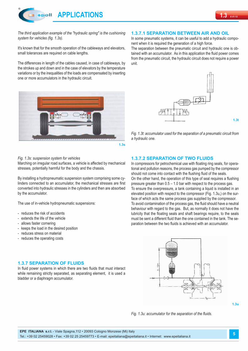
The third application example of the "hydraulic spring" is the cushioningsystem for vehicles (fig. 1.3s).
It's known that for the smooth operation of the cableways and elevators,small tolerances are required on cable lengths.
The differences in length of the cables caused, in case of cableways, bythe strokes up and down and in the case of elevators by the temperaturevariations or by the inequalities of the loads are compensated by insertingone or more accumulators in the hydraulic circuit.
Fig. 1.3s: suspension system for vehicles Marching on irregular road surfaces, a vehicle is affected by mechanicalstresses, potentially harmful for the body and the chassis.
By installing a hydropneumatic suspension system comprising some cy-linders connected to an accumulator, the mechanical stresses are firstconverted into hydraulic stresses in the cylinders and then are absorbedby the accumulator.
The use of in-vehicle hydropneumatic suspensions:
- reduces the risk of accidents - extends the life of the vehicle - allows faster cornering - keeps the load in the desired position - reduces stress on material - reduces the operating costs
1.3.7 SEPARATION OF FLUIDS In fluid power systems in which there are two fluids that must interactwhile remaining strictly separated, as separating element, it is used abladder or a diaphragm accumulator.
APPLICATIONS E 01-121.3
EPE ITALIANA s.r.l. - Viale Spagna,112 • 20093 Cologno Monzese (Mi) Italy Tel.: +39 02 25459028 • Fax: +39 02 25 25459773 • E-mail: [email protected] • Internet: www.epeitaliana.it
1.3.7.1 SEPARATION BETWEEN AIR AND OILIn some pneumatic systems, it can be useful to add a hydraulic compo-nent when it is required the generation of a high force. The separation between the pneumatic circuit and hydraulic one is ob-tained with an accumulator. As in this application the fluid power comesfrom the pneumatic circuit, the hydraulic circuit does not require a powerunit.
Fig. 1.3t: accumulator used for the separation of a pneumatic circuit froma hydraulic one.
1.3.7.2 SEPARATION OF TWO FLUIDSIn compressors for petrochemical use with floating ring seals, for opera-tional and pollution reasons, the process gas pumped by the compressorshould not come into contact with the flushing fluid of the seals. On the other hand, the operation of this type of seal requires a flushingpressure greater than 0.5 – 1.0 bar with respect to the process gas. To ensure the overpressure, a tank containing a liquid is installed in anelevated position with respect to the compressor (Fig. 1.3u,) on the sur-face of which acts the same process gas supplied by the compressor. To avoid contamination of the process gas, the fluid should have a neutralbehaviour with regard to the gas. But, as normally it does not have thelubricity that the floating seals and shaft bearings require, to the sealsmust be sent a different fluid than the one contained in the tank. The se-paration between the two fluids is achieved with an accumulator.
Fig. 1.3u: accumulator for the separation of the fluids.
5
1.3t
1.3s
1.3u

1.3.7.2 SEPARATION OF TWO GASESIn systems that can be damaged by the infiltration of moisture throughthe tank breather filter, or in the case of pressurized tanks with nitrogento prevent condensation due to temperature changes, compensation involume changes is provided by an accumulator (Fig. 1.3v).
Fig. 1.3v: accumulator for the volume compensation.
EPE ITALIANA s.r.l. - Viale Spagna,112 • 20093 Cologno Monzese (Mi) Italy Tel.: +39 02 25459028 • Fax: +39 02 25 25459773 • E-mail: [email protected] • Internet: www.epeitaliana.it
APPLICATIONSE 01-121.3
6
Reproduction is forbidden.In the spirit of continuous improvement, our products may be changed.
1.3v

CERTIFICATIONS E 01-121.4
EPE ITALIANA s.r.l. - Viale Spagna,112 • 20093 Cologno Monzese (Mi) Italy Tel.: +39 02 25459028 • Fax: +39 02 25 25459773 • E-mail: [email protected] • Internet: www.epeitaliana.it
1.4 DESCRIPTIONAccumulators are pressure vessels subjected to the specific currentregulations or accepted ones of the Countries where they will be in-stalled.For all the European Countries, design, construction and accumulatortesting must be carried out according to the Directive 97/23/EC onPressure Equipment.EPE ITALIANA, also in virtue of the quality system using EN ISO9001:2000, works according to forms H and H1 of total quality guaran-tee and design control issued by the Notify Body. The above mentioned Directive includes the pressure equipment thatexceeds 0.5 bar. So all the accumulators are involved in this Directiveeven if it provides different procedures of testing and certification.Please keep in mind that accumulators up to 1 litre of volume, even ifmanufactured according to the Directive 97/23/EC, are not marked ECand are not provided with the conformity declaration.For volumes higher than 1 litre, after the testing, each accumulator isstamped with the mark CE followed by the number that identifies theNotify Body.For these high pressure and low pressure accumulators, the docu-mentation necessary includes the conformity declaration and the ope-rator’s manual.It is also possible to supply accumulators in accordance with DirectiveATEX 94/9/EC (enclosure VIII) and with harmonized regulations EN13463-1 related to non-electrical equipment to be used in environmentwith potentially explosive atmosphere and to be included into the clas-sification ATEX EC II2GcT4.EPE ITALIANA provides also other tests and certifications for thoseCountries in which EC regulations are not accepted:- ASME-U.S. for USA, Canada, South Africa, etc..- ML (ex SQL) for China.- Australian Pressure Vessel Standard AS1210-1997 for Australia.- GOST for Russia.- RTN - Rostechnadzorfor Ukraine- DDP passport for Algeria- RINA and in some cases BS-L Lloyd’s Register and GermanischerLloyd for naval construction.- For other Countries, which require a specific test, accumulators arein any case manufactured according to the European Directive but aresupplied without EC marking and with factory test only.The documentation related to each regulation is normally provided ina proper envelope along with the goods. If it’s not available, it will besent by post or in another way as soon as possible.In order to define correctly both the price and the availability, it is ne-cessary that in the inquiry it is mentioned the required certification.
1.4.0 REPORT TESTAll EPE components are completely tested and, upon request, you canreceive the certificate of inspection by the factory.
1.4.1 TR CERTIFICATEIn most of cases, for importing products into the Russian Federationand former Soviet republics (Belarus, Ukraine, Kazakhstan), you musthave various product certificates. The most common one is the TR cer-tificate. This certificate confirms to the end user that the product com-plies with certain regulations on safety of the Country. Without thecertification, the goods cannot be cleared and the end user (importer)
cannot start-up or use the product because it is classified not safe.
1.4.2 AUSTRALIAN PRESSURE VESSEL STANDARD
In Australia, it is necessary to define the level of risk that a vessel underpressure represents.The level of risk is a ok of: volume to pressure, type of contente fickle/un-stable, its compressibility, operating conditions (static, movable, proximityto public, etc.). The degree of risk level is expressed in the Australian Standard withsome letters according to “AS4343-1999 - Equipment under pressure -Level of risk”.Any pressure vessel that has a level of risk higher than the level “E”should belong to a registered drawing. The registration of the drawings is issued by a Government agency inevery State of Australia called "Work Safe Australia".The "Work Safe" will issue the registrations only for vessels under pres-sure showing to be in accordance with Australian standards: AS1210-1997 - pressure vessels - and, normally, this registration is accepted bythe other Australian States.
1.4.3 ML (EX SQL) - CHINAWith the entry of China into the WTO (World Trade Organization), theChinese State Council has officially issued (02/19/2003) the new regu-lations on safety supervision of special equipment to be entered in theChinese market. The organization “General Administration of Quality Supervision Inspec-tion and Quarantine” (AQSIQ) was authorized to take care of the directcontrol and management of this special equipment used in China. To this control system must therefore be subject even the special equip-ment that are imported into China from all over the world. In place of Safety Quality License Office (SQLO), the offices of SELO(Special Equipment Licensing Office) directly under AQSIQ, become thenew operational reference. SELO is solely responsible for the management of documentation andfor the evaluation of the manufacturer in order to obtain of the license(Manufacture License ML). EPE ITALIANA was authorized by SELO to export its products in Chinawith License ML No. TS2200710-2012.
1.4.4 RINARINA certification for the marine industry. RINA is a third party that,in accordance with its rules, tests and certifies various pressure equip-ment that will be used in the marine industry. RINA is an associate member of IACS and is authorized to act on behalfof the Italian administration in accordance with EU Directive 94/57 andabout 70 other flag administrations.
1
TPTP1.4a
EPE ITALIANA s.r.l. - Viale Spagna,112 • 20093 Cologno Monzese (Mi) Italy Tel.: +39 02 25459028 • Fax: +39 02 25 25459773 • E-mail: [email protected] • Internet: www.epeitaliana.it
CERTIFICATIONSE 01-121.4
1.4.7 ASME-U.S.ASME (American Society of Mechanical Engineers) is an organizationthat regulates the design and manufacture of pressure vessels. Accu-mulators are categorized as unfired pressure vessels and fall under thejurisdiction of ASME Code when required by State law. Accumulators specifically fall under the section of the code referred toSection VIII, Division 1. This section requires certification on vessels withinternal diameters of 6” or greater and with the “U” symbol as evidencethat they were designed and manufactured in accordance with the Code.The “U” symbol is an internationally recognized symbol of design andquality manufacturing.The essential criteria of ASME Certification is a requirement of strengthand material traceability. Accumulators must be manufactured with ma-terials that meet ASME specifications and require a design factor of 4:1in the ratio of burst pressure to rated pressure. This 4:1 requirement is mandatory for all accumulators with ASME Cer-tification with the exception of those that comply with a specific rule withinthe Code called “Appendix 22”.Appendix 22 permits that accumulators manufactured with “forged”shells, with connections of a specified maximum size, may be certifiedwith a design factor of 3:1 in the ratio of burst pressure to rated pres-sure.ASME requires that each vessel is marked with the design pressure atthe Minimum Design Metal Temperature (MDMT) for the vessel.ASME Certification requires third party surveillance of an approved qua-lity system and requires witness by a third party of all hydrostatic testing.Currently, unlike many other standards around the world, there is noASME national requirement for periodic inspection of accumulators afterinstallation. However, local laws would dictate such inspections.
1.4.8 97/23/EC EUROPEThe Pressure Equipment Directive is one of the series of technical har-monization directives covering subjects such as machinery, simple pres-sure vessels, gas appliances, etc., which were identified by the EuropeanCommunity’s program for the elimination of technical barriers to trade.The purpose of the PED is to harmonize national laws of Member Statesregarding the design, manufacture, testing and conformity assessmentof pressure equipment and assemblies of pressure equipment.The program aims to ensure the free placing on the market and puttinginto service of relevant equipment within the European Union and theEuropean Economic Area.The Directive requires that all pressure equipment and assemblies withinits scope must be safe when placed on the market and put into service.The Pressure Equipment Directive applies to the design, manufactureand conformity assessment of pressure equipment and assemblies ofpressure equipment with maximum allowable pressure greater than 0.5bar above atmospheric pressure (i.e.:1.5 bar of absolute pressure).The PED Conformity Assessment Forms apply to all accumulators usingfluids of Group 2 (i.e.: non-hazardous), with a volume greater than 1 litreand a product of service pressure (PS) and volume (V) greater than 50bar x litre or for any pressure vessel where PS exceeds 1000 bar.PED applies in the member States of the European Union (EU) and theEuropean Economic Area (EEA). Similar requirements to PED have been
adopted by many other countries, which joined the European Union.The EU member States are: Austria, Belgium, Bulgaria, Cyprus, Den-mark, Estonia, Finland, France, Germany, Greece, Ireland, Italy, Latvia,Lithuania, Luxembourg, Malta, Netherlands, Poland, Portugal, CzechRepublic, Romania, Slovakia, Slovenia, Spain, Sweden, Hungary, andUnited Kingdom.The European Economic Area (EEA) includes the 27 EU countries listedabove, plus Iceland, Liechtenstein, Norway and Switzerland.
1.4.9 ATEX (94/9/EC)Fall within the scope of the Directive 94/9/EC also non-electrical equip-ment that have to be used in potentially explosive atmospheres so theymust be certified Atex according to the customer’s risk area. See section0.8.As required by the regulation 94/9/EC, in addition to the deposit of thetechnical dossier, EPE ITALIANA monitors its internal production andconstantly checks that the production cycle is consistent with the riskanalysis performed on the equipment and it carries out a self-certification.
1.4.10 DNV«Det Norske Veritas» (DNV) Certification, section «Maritime».DNV certifies all materials, components and systems that are relevantto the operation of ships in terms of safety and quality. The Classificationis a particular type of certification, which is used to confirm that the shipsand all structures that exist within it conform to the requirements. These requirements are specified in the regulations of DNV. The classi-fication, in fact, provides that the same company that performs the clas-sification, namely the institution of the third party, establishes therequirements.
1.4.11 RTN - ROSTECHNADZORRTN Rostekhnadzor Certification The FSETAN RTN ROSTECHNADZOR certificate (former Gosgortek-nadzor).The FSETAN and RTN RosTechNadzor permissions for the use of te-chnological systems (production lines) are required in dangerous indu-strial areas during flammable and explosive processes and for the useof the related equipment as well as in any other field that may cause dan-ger to the ecology and the human being. The Permissions are grantedby the Federal Ecological, Technological and Atomic Monitoring Serviceaccording to expert conclusions on the industrial safety carried out byspecialists of the Organization. Therefore, all components used on theseplants are accompanied by its passport RTN.
1.4.12 ALGERIAN PASSPORTEPE Italiana is able to supply its components with the Algerian passportfor all applications that it’s required.After the approval of the preliminary dossier from the Algerian Ministryof Energy and Certification with endorsement by the Algerian Consulatein Italy and the Italian Chamber of Commerce, will be issued the finaldossier in French language and carried out, by third party, the pressuretest on the equipment subjected to this certification.
2
Reproduction is forbidden.In the spirit of continuous improvement, our products may be changed.

ELASTOMERS E 01-121.5
EPE ITALIANA s.r.l. - Viale Spagna,112 • 20093 Cologno Monzese (Mi) Italy Tel.: +39 02 25459028 • Fax: +39 02 25 25459773 • E-mail: [email protected] • Internet: www.epeitaliana.it
1.5.1 DETAILS OF THE BLADDERS AND/OR SEALS MATERIAL
The bladders can be made of various types of elastomers. To obtain thethermal and chemical compatibility with the fluid used, you must selectthe proper elastomer, depending on the fluid used and the working tem-perature. For more precise information than the specifications outlinedbelow, please contact our technical service.
1.5.2 “P” NITRILE RUBBER (NBR)Nitrile rubber NBR is the generic name of the acryl-nitrile butadiene com-pound. The content of nitrile-acrylate is greater than 33%, so you have theright balance between a good compatibility with oils and fuels, while maintai-ning good flexibility at low temperatures. The NBR rubber is highly resistantto ozone and weathering. Heat resistance up to 80°C and for short periodsup to 90°C (at higher temperatures, the aging is accelerated). Resistance tolow temperatures down to -20°C, for short periods up to -25° C.
Chemical compatibility:- aliphatic hydrocarbons (propane, butane, gasoline, oils, mineral grea-
ses, diesel fuel, fuel oil, kerosene) - mineral greases and oils- HFA, HFB, HFC fluids- many dilute acids, alkalis, salt solutions - water- water glycol
Not compatible with:- fuels with high aromatic content (i.e. premium gasoline) - aromatic hydrocarbons (benzene) - chlorinated hydrocarbons (trichloroethylene) - polar solvents (ketone, acetone, ethylene esters of acetic acid) - strong acids - brake fluids based on glycol - water glycol - poor resistance to ozone, weathering and aging.
1.5.3 “F” NITRILE RUBBER FOR LOW TEMPERATURES
The same as with standard nitrile and most types of freon. It has lowercontent of acrylic nitrile with respect to the standard, so it is best suita-ble to work at low temperatures but the chemical resistance to various li-quids is slightly lower. Working temperature –40°C +70°C.
1.5.4 “H” NITRILE RUBBER FOR HYDROCARBONS
Compatible with normal gasoline, super low-aromatic ones, combinedheavy oil and all fluids of standard nitrile. Working temperature –10°C+90°C
1.5.5 “K” HYDROGENATED NITRILE (HNBR) The hydrogenated nitrile rubber is obtained by adding hydrogen to thecompound of the NBR rubber, which imparts superior mechanical proper-ties, outstanding abrasion resistance, high tensile strength, excellent re-sistance to high temperatures, low gas permeability. Heat resistance upto 130°C, with higher peaks for short periods of up to 150°C. Resistanceto low temperatures up to -30°C. Chemical compatibility greater than the NBR rubber.
1.5.6 “B” BUTYL (IIR)The butyl rubber has low gas permeability and good electric insulation ca-pacity. Heat resistance up to 100°C, with higher peaks for short periodsof up to 120°C. Resistance to low temperatures up to -30°C.
Chemical Compatibility:- hot water up to 100°C - brake fluids based on glycol - many acids and bases - salt solutions- polar solvents such as alcohols, ketones and esters - polyglycol-based hydraulic fluids (HFC fluids) and bases of phospho-
ric acid esters (HFD-R fluids) - silicone oils and greases- Skydrol 500 e 7000- resistance to ozone, weathering and aging
Not compatible with:- mineral oils and greases - fuels - chlorinated hydrocarbons
1.5.7 “E” ETHYLENE-PROPYLENE (EPDM)EPDM is a rubber derived from the copolymerization of ethylene withpropylene and diene, so it has features particularly suitable to contactwith hydraulic fluids based on phosphate esters; it can be also used withfluids of the glycol-based brake systems. Heat resistance up to 100°,with higher peaks for short periods of up to 120°C . Resistance to lowtemperatures up to -30°C.
Chemical Compatibility:- hot water up to 100°C - brake fluids based on glycol - many organic and inorganic acids - detergents, sodium and potassium solutions- hydraulic fluids based on phosphate esters (HFD-R) - silicone oils and greases- many polar solvents (alcohol, ketones, esters) - Skydrol 500 and 7000- resistance to ozone, weathering and aging
Not compatible with:- mineral oils and greases - fuels
1.5.8 “N” CHLOROPRENE (CR)Trade name NEOPRENE. Chloroprene rubber is one of the first rubbers created synthetically. Giventhe high content of chlorine, vulcanizing items have good flammability.They burn under direct action of the flame, but go out when it goes away.The compatibility to the oil is medium, good mechanical properties in thewide temperature range of use. Heat resistance up to 100°C , with hi-gher peaks for short periods of up to 110°C . Resistance to low tempe-ratures up to -30°C.
Chemical Compatibility:- mineral paraffin oils
1

EPE ITALIANA s.r.l. - Viale Spagna,112 • 20093 Cologno Monzese (Mi) Italy Tel.: +39 02 25459028 • Fax: +39 02 25 25459773 • E-mail: [email protected] • Internet: www.epeitaliana.it
ELASTOMERSE 01-121.5
- silicone oils and greases- water and aqueous solutions - refrigerants (ammonia, carbon dioxide, Freon)- naphthenic mineral oils - low molecular aliphatic hydrocarbons (propane, butane, gasoline) - brake fluids based on glycol - better resistance to ozone, weathering and aging than in NBR rubber.
Not compatible with:- aromatic hydrocarbons (benzene) - chlorinated hydrocarbons (trichloroethylene) - polar solvents (ketones, esters, ethers, acetone).
1.5.9 “Y” EPICHLOROHYDIN (ECO) The epichlorohydrin rubber is a copolymer which has good compatibilitywith mineral oils, fuels and ozone. The high temperature resistance is good;it still has a good elasticity at low temperature, while the gas permeability isnot excellent. Heat resistance up to 110°C, with higher peaks for short pe-riods of up to 120°C. Resistance to low temperatures up to -30°C.
Chemical Compatibility:- mineral oils and greases - aliphatic hydrocarbons (propane, butane and gasoline) - silicone oils and greases- water at ambient temperature - resistance to ozone, weathering and aging
Not compatible with:- aromatic hydrocarbons and chlorinated solutions- ketones and esters - non-flammable hydraulic fluids of HFD-R and HFD-S groups- brake fluids based on glycol
1.5.10 “V” FLUOROCARBON (FPM)The trade name ("DuPont") is VITON®. The fluorocarbon rubber has ex-cellent resistance to high temperatures, ozone, oxygen, mineral oils, syn-thetic hydraulic fluids, fuels and many chemicals and organic solutions.In the field of low temperatures, its behaviour is not optimal. The permea-bility to gases is very low, similar to that of butyl. Heat resistance up to180?, for short periods of up to 200?. Resistance to low temperatures upto - 10?.
Chemical Compatibility:- mineral oils and greases - non-flammable fluids of HFD group - silicone oils and greases- animal and vegetable oils and greases - aliphatic hydrocarbons (gasoline, butane, propane, natural gas) - aromatic hydrocarbons (benzene, toluene) - chlorinated hydrocarbons (tetrachloroethylene, carbon tetrachloride) - fuels (normal, premium and containing methanol) - good resistance to ozone, weathering and aging.
Not compatible:- polar solvents (acetone, methyl ethyl ketone, ethyl acetate, diethyl
ether, dioxane) - Skydrol 500 and 7000
- brake fluids based on glycol - ammonia gas, amines, alkali - superheated steam - low molecular organic acids (formic and acetic acid).
1.5.11 POLYURETHANE (HPU) The H-PU polyurethane is a copolymer, based on aromatic isocynateand diols. Compared to all other elastomers, it has excellent wear resistance, ex-cellent resistance to extrusion and high elasticity. The gas permeabilityis good compared to that of IIR. Heat resistance: up to approx. +80°C;resistance to low temperatures: up to approx. –20°C.
Chemical Compatibility: - pure hydrocarbons - natural oils and greases - silicone oils and greases - water up to +50°C- resistance to ozone and aging
Not compatible with:- ketones, esters, ethers, alcohols, glycols - hot water, steam, alkalis, amines, acids
Resistant to:- oil, petrol, hot water, hot air, ozone, synthetic and native esters
Not resistant to:- conc. Acids, conc. Iyes, conc. alcohols and aromatic solvents.
1.5.12 SILICON-FLUORINE (MFQ)The rubber MFQ contains in its molecule, as well as methyl groups, eventrifluoropropyl groups. The physical and mechanical properties are com-parable to those of silicone rubber (MVQ). In comparison to silicone(MVQ), the silicon fluoride (MQF) shows a significantly higher compati-bility to fuels and mineral oils, while resistance to the hot air is slightlylower. Heat resistance: up to approx. 150?. (max. 180°C)Resistance to low temperatures: up to approx. +50°C
Chemical Compatibility:- mineral aromatic oils (i.e. ASTM Oil No. 3) - fuels - aromatic low molecular hydrocarbons (i.e. benzene, toluene) - engine oils and aliphatic type transmissions- animal and vegetable oils and greases - brake fluids based on glycol - non-flammable hydraulic fluids, HFD-R and HFD-S fluids- chlorinated aromatic hydrocarbons with high molecular content (i.e.
Chlophen), chlorinated diphenyl- water up to +70?- dilute salt solutions - resistance to ozone, aging and weathering
Not compatible with:- superheated steam over 100°C - acids and alkalis
2
ELASTOMERS E 01-121.5
EPE ITALIANA s.r.l. - Viale Spagna,112 • 20093 Cologno Monzese (Mi) Italy Tel.: +39 02 25459028 • Fax: +39 02 25 25459773 • E-mail: [email protected] • Internet: www.epeitaliana.it
- silicone oils and greases- low molecular chlorinated hydrocarbons (i.e. trichloroethylene)
1.5.12 TEFLON (PTFE)Normally it is better known by its trade name Teflon®, in which other
stabilizers and plasticizers are added to the polymer to improve the cha-racteristics depending on the application. It's a plastic smoother to thetouch and resistant to high temperatures (up to 200°C). The main features are: - the complete chemical inertia, so it's not attacked by almost all chemi-
cal compounds (with the exception of molten alkali metals, fluorine athigh pressure and some fluorine compounds under particular condi-tions of temperature) and especially it does not change the fluids withwhich is placed in contact, such as high purity fluids for the electro-nics industry
- the complete insolubility in water and in any organic solvent - good electric quality (65 kV / mm of dielectric strength) - excellent resistance to fire: it does not propagate the flame - Excellent flow properties on the surface: the coefficient of friction is the
lowest among the industrial sealing products- Non-stick: the surface cannot be glued (contact angle is of 127°)These characteristics take on added importance when you take into ac-count that remain virtually unchanged in a range of temperatures from -50°C and 150°C (max. 200°C).
Chemical Compatibility:- Teflon has a high chemical compatibility with most fluids and chemicals
used.
Not compatible with:- hardly compatible with fuel oils in general
1.5.13 THE GAS PERMEABILITY ISSUE SIMPLIFIED
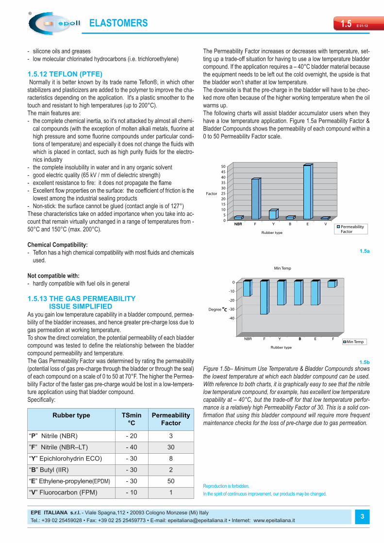
As you gain low temperature capability in a bladder compound, permea-bility of the bladder increases, and hence greater pre-charge loss due togas permeation at working temperature.To show the direct correlation, the potential permeability of each bladdercompound was tested to define the relationship between the bladdercompound permeability and temperature.The Gas Permeability Factor was determined by rating the permeability(potential loss of gas pre-charge through the bladder or through the seal)of each compound on a scale of 0 to 50 at 70°F. The higher the Permea-bility Factor of the faster gas pre-charge would be lost in a low-tempera-ture application using that bladder compound.Specifically:
The Permeability Factor increases or decreases with temperature, set-ting up a trade-off situation for having to use a low temperature bladdercompound. If the application requires a – 40°C bladder material becausethe equipment needs to be left out the cold overnight, the upside is thatthe bladder won’t shatter at low temperature.The downside is that the pre-charge in the bladder will have to be chec-ked more often because of the higher working temperature when the oilwarms up.The following charts will assist bladder accumulator users when theyhave a low temperature application. Figure 1.5a Permeability Factor &Bladder Compounds shows the permeability of each compound within a0 to 50 Permeability Factor scale.
Figure 1.5b– Minimum Use Temperature & Bladder Compounds showsthe lowest temperature at which each bladder compound can be used.With reference to both charts, it is graphically easy to see that the nitrilelow temperature compound, for example, has excellent low temperaturecapability at – 40°C, but the trade-off for that low temperature perfor-mance is a relatively high Permeability Factor of 30. This is a solid con-firmation that using this bladder compound will require more frequentmaintenance checks for the loss of pre-charge due to gas permeation.
3
Rubber type TSmin°C
PermeabilityFactor
“P” Nitrile (NBR) - 20 3
”F” Nitrile (NBR–LT) - 40 30
“Y” Epichlorohydrin ECO) - 30 8
“B” Butyl (IIR) - 30 2
“E” Ethylene-propylene(EPDM) - 30 50
“V” Fluorocarbon (FPM) - 10 1Reproduction is forbidden.In the spirit of continuous improvement, our products may be changed.
NBR BYFNBR
Rubber type
VE
1.5b
°c °c
BYFNBR FEB
Rubber type
1.5a
