general · pdf file · 2012-02-29general 2 2.0 know your indica vista ......
TRANSCRIPT

GENERALGENERALGENERALGENERALGENERAL

1
GENERAL
2. 0 Introduction to Indica Vista 2
2. 1 Good workshop practice and safety precautions 3
2. 2 Precautions for electric circuit service 5
2. 3 Lifting, Jacking and Towing points 7
2. 4 Jack and tool bag location in vehicle 9
2. 5 Numbering system 10
2.5.1 Chassis numbering 10
2.5.2 Chassis type and sales designations 10
2.5.2 Aggregate numbering 10
2.5.3 Location of chassis and aggregate numbering system 10
2.6 Technical specification 13
2.7 Tightening torque of standard bolts and nuts 16
2.8 Recommended lubricant and coolants 17
2.9 Vehicle dimensions 18
CONTENTS
SR.NO. DESCRIPTION PAGE NO.

GENERAL
2
2.0 KNOW YOUR INDICA VISTA
Your INDICA VISTA comes from a family of new cars
that are being rolled out from the Tata Motors’ stables.
It is the outcome of research & development by Tata
Motors Limited. The INDICA VISTA incorporates all
the advanced features of Tata Motors precision and
advanced technology.
The INDICA VISTA is a hatchback having five doors
with an ergonomically designed cab with added
features like collapsible and adjustable power
steering, central locking, power windows,
sophisticated HVAC system, multi adjustable Driver
and co-driver seats having provision for lumbar as
well as head restraint adjustment. The INDICA VISTA
is provided with a set of rear swept stylish head lamps
which are biggest in it’s class
The INDICA VISTA is powered by new generation
engines that have been designed to deliver consistent
and optimum performance under the toughest
conditions.
The INDICA VISTA has vacuum assisted
independent hydraulic brakes with disc brakes in front
and drum brakes for the rear wheels. The suspension
has been designed to provide a comfortable ride.
This design incorporates solutions to eliminate
vibrations caused due to road undulations and
provide better stability in all driving conditions coupled
with reduced noise levels in the car.
In addition to all these, TATA vehicles are backed by
a well established service network with trained and
skilled manpower that ensures proper maintenance.

3
GENERAL
2.1 GOOD WORKSHOP PRACTICES &
SAFETY PRECAUTIONS :
n Always ensure that all the repair / maintenance
work carried out should be as per the instructions
provided in the workshop manual.
n Use protective clothing, apron, hand gloves, and
safety shoes while working in the workshop. Do
not wear watch, rings and belt while serving the
vehicle.
n Keep your work area, equipment and tools clean
at all times.
n Make sure you use the proper tool for the job and
use it the right way. The improper tool or its
incorrect use can damage the part you are
working on or cause injury or both.
n Never keep the tools on the floor/vehicle. The
tools should be kept in the tool box after use.
n Cover fenders, seats, steering wheel and any
other parts those are likely to get scratched/soiled
before starting any service work (Fig. 1).
Fig. 1
n While servicing the vehicle in engine running
condition make sure that the gear shifting lever is
in neutral position and parking brake is fully
applied. Never run the engine without proper
ventilation and adequate means of getting rid of
exhaust gases.
n Prior to removing or disassembling parts, they
must be inspected carefully to isolate the cause
Fig. 2
for which the service is called for (Fig. 2).
n All the reusable dismantled components must be
kept in a clean enamel coated white tray
sequentially in an orderly manner to facilitate their
Fig. 3
accurate and proper reinstallation (Fig. 3).
n Never reuse the parts like oil seals, gaskets,
packing, O-rings, locking washers, split pins, self
locking nuts and certain other parts.
n Plug the ports / openings of aggregates such as
FIP / Injectors, TMC, etc., whenever removed from
the car.

GENERAL
4
n For correct reinstallation of vacuum fuel hoses
attach tag describing the correct positions (Fig.
4).
Fig. 4
n Make sure only the branded lubricants, coolant,
corrosion protection coatings and sealants are
used.
n Check all the lines for leaks related to the systems
like fuel, oil, coolant, vacuum, exhaust and brakes
after servicing (Fig. 5).
Fig. 5
n For vehicles equipped with fuel injection systems
do not disconnect the fuel line between the injector
and the fuel pump without releasing the fuel
pressure or fuel can be sprayed out under
pressure (for diesel).
Precaution for Catalytic Converter (MPFI PetrolEngine) :
Caution : If large amount of unburnt fuel goes into
the converter, it may overheat and create a FIRE
hazard.
To prevent this, observe the following precautions :
n Use only unleaded gasoline.
n Engine compression checks should be carried out
within the shortest possible time.
n If necessary then only conduct a spark jump test
within the shortest possible time.
n Do not run the engine when the fuel tank is nearly
empty to avoid engine misfire and damage to
catalytic converter.
NOTE :
For details on the catalytic converter precautions
please refer to exhaust system of this manual.

5
GENERAL
2.2 PRECAUTION FOR ELECTRICAL
CIRCUIT SERVICE :
n Disconnect the negative cable of the battery while
servicing the electrical parts that do not require
battery power and insulate the negative terminal
Fig. 6
properly (Fig. 6).
n While removing the battery first disconnect the
negative cable and then the positive cable. While
reinstalling the battery, first connect the positive
cable and then negative cable.
n Be sure to turn the ignition switch off before
disconnecting and connecting coupler to avoid
electronic parts damage (Fig. 7).
n Do not touch the electrical terminals of parts which
use microcomputers (e.g. electronic control units
like ECM etc.) to avoid damage to these parts from
static electricity from your body (Fig. 8)
n Always use the correct voltmeter, ohmmeter for
taking measurement to avoid damage to the
electronic control unit and sensors.
n Make sure to insert the probe from wire harness
side of the connector for taking measurement.
n Make sure the connector halves are mating
Fig.7
Fig. 8
properly and terminals seating precisely in the
connector body (Fig. 8)
n Dirt / corroded terminals result in improper contact.
The terminals should be cleaned carefully.
n Improper contact pressure between mating
terminals disturbs the connectivity between them.
n Replace the damaged connector body to avoid
exposure of the terminals in case of inadequate
contact pressure.

GENERAL
6
n Ensure proper connection between the terminal
to the wire. Rectify the loose connection by
repairing / replacing the wire harness (Fig. 9)
n Worn out insulation of the wire may result in short
circuit.
n Avoid water entering the connectors.
Fig. 9

7
GENERAL
2.3 LIFTING, JACKING, TOWING POINTS
USING THE TWO POST LIFT
Make sure you follow the manufacturer’s instructions
while lifting the car on two post lift as shown in (Fig10).
Fig. 10
Always ensure vehicle balance in service while
applying two post lift to under body.
Care should be taken that the two post lift arm is not
in contact with the bracket, brake or fuel pipes etc.
Before servicing, make sure to lock the lift after the
vehicle is lifted up.
Following fig shows the front and the rear jacking
points by two post lift
Fig. 11
FRONT JACKING POINTS
Fig. 12
REAR JACKING POINTS

GENERAL
8
Fig. 13 a
Fig. 13 b
Do not apply the jack against any part which may
get deformed.
If front end or rear end of the vehicle is to be jacked
ensure the wheels on ground and the parking brake
is applied.
TOWING THE VEHICLE : (Fig. 14)
Fig. 14
n For towing a car, the best way is to use a wrecker.
Alternatively use a rigid tow bar.
n Avoid using a flexible cable or rope as your car
may crash into the car towing your car when it
stops suddenly.
n Switch ‘ON’ the hazard warning signals of both
the cars to warn other road users.
n Where possible, keep the engine idling so that
power steering assistance and brake vacuum are
available.
n Limit the speed to 20-30 Kmph.
n In case of brake failure, use the parking brake to
control the car.
USING THE FLOOR JACK:
Use the jacks at the locations as shown in the figs.13 a, 13 b

9
GENERAL
Fig. 16 (Near spare wheel)
2.4 JACK AND TOOL BAG LOCATION IN
VEHICLE:
1. JACK LOCATION :
2. TOOL BAG LOCATION :
Fig. 17 (Below parcel shelf, near suspension tower)
Fig. 15
REAR TOW HOOK : (Fig. 15)
n Boltable tow hook is provided in the toolkit.
n Remove cover on rear bumper.
n Bolt the tow hook (ensure proper fitment).
n Whenever tow hook is not required unscrew the
tow hook and keep it in toolkit.
n Press the cover to close the hole for tow hook in
rear bumper.

GENERAL
10
2.5 NUMBERING SYSTEM :
2.5.1 CHASSIS NUMBERING SYSTEM
Chassis number consists of 15 digits (6 barrels) as given below :
MAT xxxxxx x x x xxxxx
Indicates produced in Serial No. to start every
TATA MOTORS LTD. PUNE year with 00001 on First
JAN for RHD &
Chassis type No. First APRIL for LHD
(Model,execution
wheel base etc.) Drive Type -R-For RHD
L-LHD
Year of production Plant LocationP for K Block,Pune
YEAR CODE (ISO 3779)
1.1.2008 to 31.12.2008 8
1.1.2009 to 31.12.2009 9
1.1.2010 to 31.12.2010 A
1.1.2011 to 31.12.2011 B
1.1.2012 to 31.12.2012 C
1.1.2013 to 31.12.2013 D
1.1.2014 to 31.12.2014 E
2.5.2 CHASSIS TYPE & SALES DESIGNATION :
Chassis no Sales Designation Model Description EC Whole Vehicle TypeApproval Number (ECWVTA)
611248 Tata Indica Vista High TATA INDICA VISTA HIGH e11*2007/46*0052
1.4L SAFIRE 75PS,
EURO -V,LHD
611271 Tata Indica Vista Aura TATA INDICA VISTA AURA e11*2007/46*0052
1.4L SAFIRE 75PS
EURO-V LHD

11
GENERAL
2.5.3 AGGREGATE NUMBERING - NUMBERING FOR SAFIRE ENGINES:
The Label gives the following information :
1. Supplier identification code - 2 Numerical Digits
2. Assembly Code - 1 Numerical Digit
3. Engine number plate - 7 Numerical Digits
4. Engine number plate check digit - 1 Numerical Digit
5. Engine drawing number - 11 Numerical Digits
6. Engine type code - 4 Numerical Digits
7. Production line code - 2 Numerical Digits
8. Filler - 1 Numerical Digit set to fixed zero to uniform the label to the standards.
9. Label cheack digit - 1 Numerical Digit
Homologated Type Dwg.Code Serial number
160D1000
1 2 3 4 5 6 7 8 9
GENERAL
12
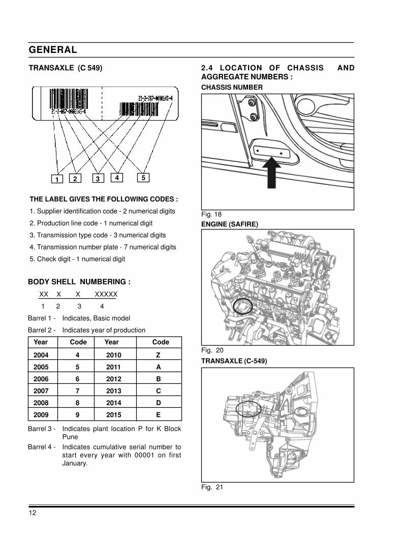
TRANSAXLE (C-549)
2.4 LOCATION OF CHASSIS AND
AGGREGATE NUMBERS :
CHASSIS NUMBER
Fig. 20
Fig. 21
ENGINE (SAFIRE)
Fig. 18
THE LABEL GIVES THE FOLLOWING CODES :
1. Supplier identification code - 2 numerical digits
2. Production line code - 1 numerical digit
3. Transmission type code - 3 numerical digits
4. Transmission number plate - 7 numerical digits
5. Check digit - 1 numerical digit
TRANSAXLE (C 549)
1 2 3 4 5
BODY SHELL NUMBERING :
XX X X XXXXX
1 2 3 4
Barrel 1 - Indicates, Basic model
Barrel 2 - Indicates year of production
Year Code Year Code
2004 4 2010 Z
2005 5 2011 A
2006 6 2012 B
2007 7 2013 C
2008 8 2014 D
2009 9 2015 E
Barrel 3 - Indicates plant location P for K Block
Pune
Barrel 4 - Indicates cumulative serial number to
start every year with 00001 on first
January.

13
GENERAL
STEERING
STEERING
Type Power assisted Rack & Pinion - Hydraulic
Steering Wheel 380 mm
SUSPENSION
REAR AXLE
REAR AXLE
Model / Type Non driven type Twist Beam Suspension
2.6 TECHNICAL SPECIFICATION FOR TATA INDICA VISTA
ENGINE
ENGINE (PETROL) SAFIRE (75PS)
Model / Type Water Cooled Multi-point Fuel Injection Petrol Engine
No. Of Cylinders 4 Inline
Bore / Stroke 72 mm X 84 mm
Capacity 1368 cc
Max. Engine Output 55 Kw @ 6000 rpm
Max. Torque 114 Nm @ 3250 rpm
Compression Ratio 10 : 1
Firing Order 1 - 3 - 4 - 2
CLUTCH
CLUTCH
Model / Type Single Plate Dry Friction Diaphragm type
Ountside dia of clutch lining 200 mm
Friction Area 324 mm
TRANSAXLE
TRANSAXLE
Front Wheel Drive Through Constant Velocity Joints
Model / Type Synchromesh with over drive
No. of gears 5 Forward and 1 Reverse
Gear Raios 1st - 4.273
2nd - 2.238
3rd - 1.520
4th - 1.156
5th - 0.872
Rev. - 3.909
Final drive ratio 3.733
Gear shift Floor mounted with international ‘H’ pattern with Fifth & Reverse inline
SUSPENSION
Front Driven type Independently Suspended with McPherson Strut
Rear Semi-independent, Twist Beam with coil Springs and Hydraulic Shock
Absorbers
Anti-roll bar At Front

GENERAL
14
WHEELS & TYRES
WHEELS & TYRES
Tyres Radial Tubeless 175/65 R14 82T
Wheel rims 5J X 14
No. of wheels Front - 2, Rear - 2, Spare -1
ELECTRICAL
ELECTRICAL
System voltage 12V
Battery DIN44L
Alternator 12V 90A
BODY
BODY
Model / Type hatch-back, Five Door, Steel Monocoque Passenger Car
FUEL TANK
FUEL TANK
Capacity 44 Litres
BRAKES
BRAKES
Service brake Mechanical Brake assist booster, Vacuum assisted independent dual
circuit , Diagonal split Hydraulic Brake on Front & Rear through tandem
cylinder acting on all 4 wheels with Automatic wear adjuster, Foot
operated with ABS
Front brakes / Rear brakes Front : 240 mm Dia. Disc Brake / Rear : 200 mm Dia. Drum Brake
Parking brakes Lever type,Console mounted,Cable operated mechanical linkage acting
on rear wheels
MAIN CHASSIS DIMENSION (IN MM NOMINAL)
MAIN CHASSIS DIMENSION
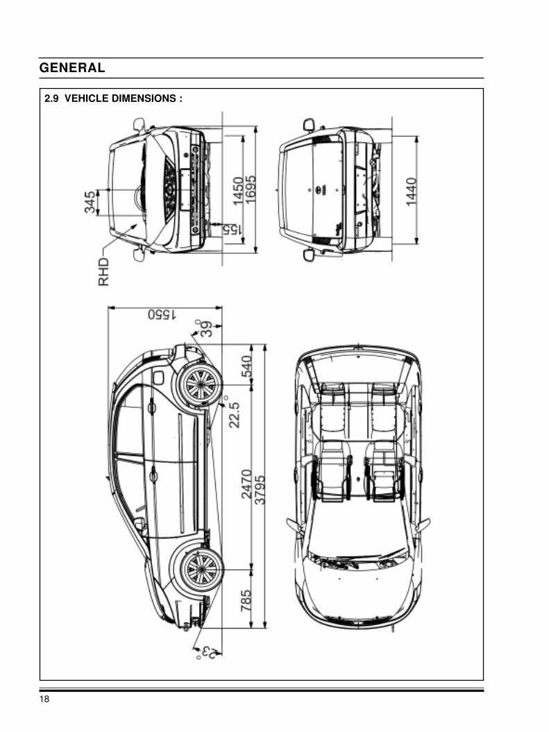
Wheel Base 2470
Track Front 1450
Track Rear 1440
Front Overhang 785
Rear Overhang 540
Overall Length 3795
Max. Width 1695 (Over Body)
Overall Height (Unladen/Laden) 1550 (Unladen)
Min. Turning Circle Dia. 10 m
Min. Turning Clearance Circle 10.6 m
Ground Clearance 155 (Unladen)
WEIGHT (KG)
WEIGHT
Complete vehicle kerb weight 1225 Euro ENCAP / 1125 Non ENCAP
Gross vehicle weight 1625 Euro ENCAP / 1625 Non ENCAP
Payload 400 Euro ENCAP / 500 Non ENCAP

15
GENERAL
PASSENGER CAPACITY
PASSENGER CAPACITY
Capacity 2 Front + 3 Rear
LUGGAGE SPACE
LUGGAGE SPACE
Net inside loading space 232 Litres

GENERAL
16
2.7 TIGHTENING TORQUES OF STANDARD BOLTS & NUTS
Wherever the tightening torques are not specified use the following values for these fasteners.
Grade Bolt or Nut Size Pitch (mm) Torque N-m Torque kg-m
Bolt 8.8
Nut 8.0
Bolt 10.9
Nut 10.0
M6
M8
M10
M12
M14
M16
M6
M8
M10
M12
M14
M16
1.0
1.25
1.5
1.0
1.75
1.5
2.0
1.5
2.0
1.5
1.0
1.25
1.0
1.5
1.0
1.75
1.5
2.0
1.5
2.0
1.5
8.5 - 10
21 - 25
41 - 51
46 - 56
72 - 88
75 - 91
113 - 138
126 -154
176 - 215
189 - 231
12 - 14
29 - 35
32 - 39
58 - 70
64 - 78
99 - 121
104 - 127
162 - 198
176 - 215
248 - 303
266 - 325
0.85 - 1.0
2.1 - 2.5
4.1 - 5.1
4.6 - 5.6
7.2 - 8.8
7.5 - 9.1
11.3 - 13.8
12.6 - 15.4
17.6 - 21.5
18.9 - 23.1
1.2 - 1.4
2.9 - 3.5
3.2 - 3.9
5.8 - 7.0
6.4 - 7.8
9.9 - 12.1
10.4 - 12.7
16.2 - 19.8
17.6 - 21.5
24.8 - 30.3
26.6 - 32.5
1. This standard is applicable to the bolts having the
following marks embossed on the bolt head and
punch mark on the nut head.
Grade
8.8 For the Bolt
10.9 For the Bolt
8 For the Nut
10 For the Nut
Note : Always use the calibrated torque wrenches.
2. Nyloc nuts and copper washer should not be
reused.

17
GENERAL
LUBRICANTS AND OILS :
Please use only recommended grades for goodperformance.
DO NOT mix grease of different brands and optional
grades. Replace old grease completely. The oil
change periods recommended in maintenance
schedule should be adhered.
Recommended grades of engine oil for range of
ambient temperature :
Ambient Engine OilTemp 0CGrade
- 5 and above SAE 15W/40
- 10 to 0 SAE 5W30
- 20 and -10 SAE 0W30
2.8 RECOMMENDED LUBRICANTS & COOLANTS
ITEM SPECIFICATION QTY
ENGINE OIL SAE 5W 40 2.9 LitresSAFIRE 75 PS (PETROL) MEETING ACEA C3
COOLANT Class II / JIS K2234 5.4 Litres(Antifreeze agent + Soft water
50 : 50 ratio)
TRANSAXLE Semi Synthetic 2.2 LitresSAE 75W80 GL4
POWER STEERING OIL ATF Dexron III 1.0 Litres
BRAKE / CLUTCH FLUID SAE J 1703, DOT 3 As required
FUEL (PETROL) : Unleaded regular grade petrol
conforming to EC specification for Euro-V and octane
rating not less than EN 228/ RON 95 (RON stands
for Research Octane Number) is recommended to
be used as fuel.
CAUTION
Do not use petrol with lead in a car fitted with
catalytic convereter. Even single fill of leaded petrol
will seriously damage the catalytic converter.
Recommended grade of Engine Oil confirming to SAE5W40 engine oil meeting ACEA C3 specification
for ambient temp. ranging from -20 to + 40 degree C.
For ambient temp. Below -20 degree C use lower
viscosity grade oil.
Transaxle : Semi Synthetic SAE 75W80 GL4.
Grease for axle bearings : Lithium base grease IPOL
IPLEX LC Grease 2
Brake fluid : SAE J 1703, DOT 3
Power Steering : ATF Dexron III
COOLANTS Qty : Approx. 5.4 Litres
Presence of dirt in coolant chokes up passages in
radiator, cylinder head and crankcase, thereby
causing overheating of engine.
To prevent rust formation and freezing of coolant
inside the passages of radiator, crankcase and
cylinder head use premixed coolant as
recommended.
It is recommended that the entire cooling system
should be drained and filled with fresh premixed
coolant.
Engine coolant antifreeze coolant as per class II/JIS
K2234.
Windscreen Washer Antifrost
Make - Antifrost- K
Concentration - 1 : 5 For 00C
1 : 1 For 100C
2 : 5 For 160C
1 : 0 For 370C
NOTE :
We strongly recommend to refill your car’s engine
coolant only at aTATA Authorised service centre.
GENERAL
18
2.9 VEHICLE DIMENSIONS :