gen5 camaro ls3 twin turbo kit install · reinstall intake manifold, the vacuum hose for the power...
TRANSCRIPT

Granatelli Motor Sports, Inc. - 1000 Yarnell Place - Oxnard, CA 93033-2454805-486-6644 - 805-486-6684 (Fax) - Hours: M-F 8AM-5PM (PST)
www.GranatelliMotorSports.com/[email protected]
Gen5 Camaro LS3 Twin Turbo Kit Install
1. Disconnect battery ground
2. Remove front wheels
3. Remove (5) push pins and (5) #20 torx screws on inner front wheel well liners and remove liners on each side
4. Remove (4) 10mm and (1) 7mm bolt that holds fascia at front corners, on each side
5. Remove (2) 10mm bolts at the bottom of the valance

6. Disconnect head light wire loom, connector is found under passenger headlight
7. Remove (6) push pins and (2) bolts along the top of fascia.
8. With two people, gently lift fascia forward and remove whole fascia assembly
9. Remove (6) bolts holding metal bumper and remove bumper
10. Disconnect outside air temp sensor (Picture reflects steps 10-12)
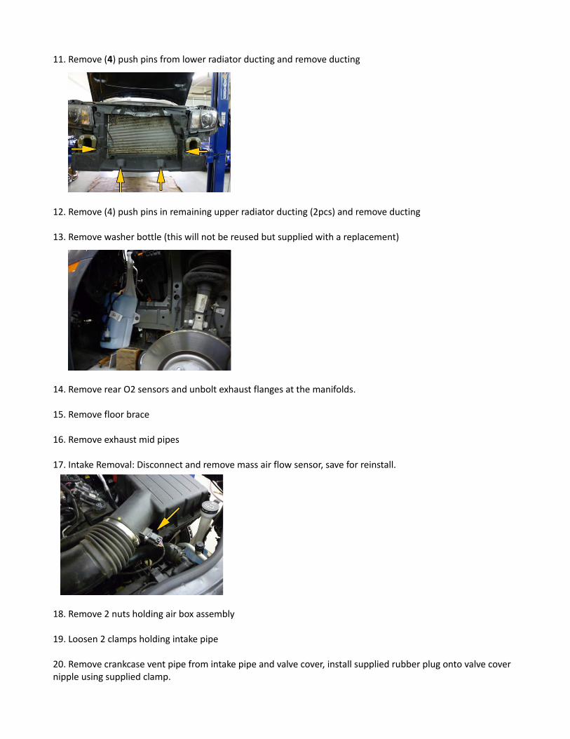
11. Remove (4) push pins from lower radiator ducting and remove ducting
12. Remove (4) push pins in remaining upper radiator ducting (2pcs) and remove ducting
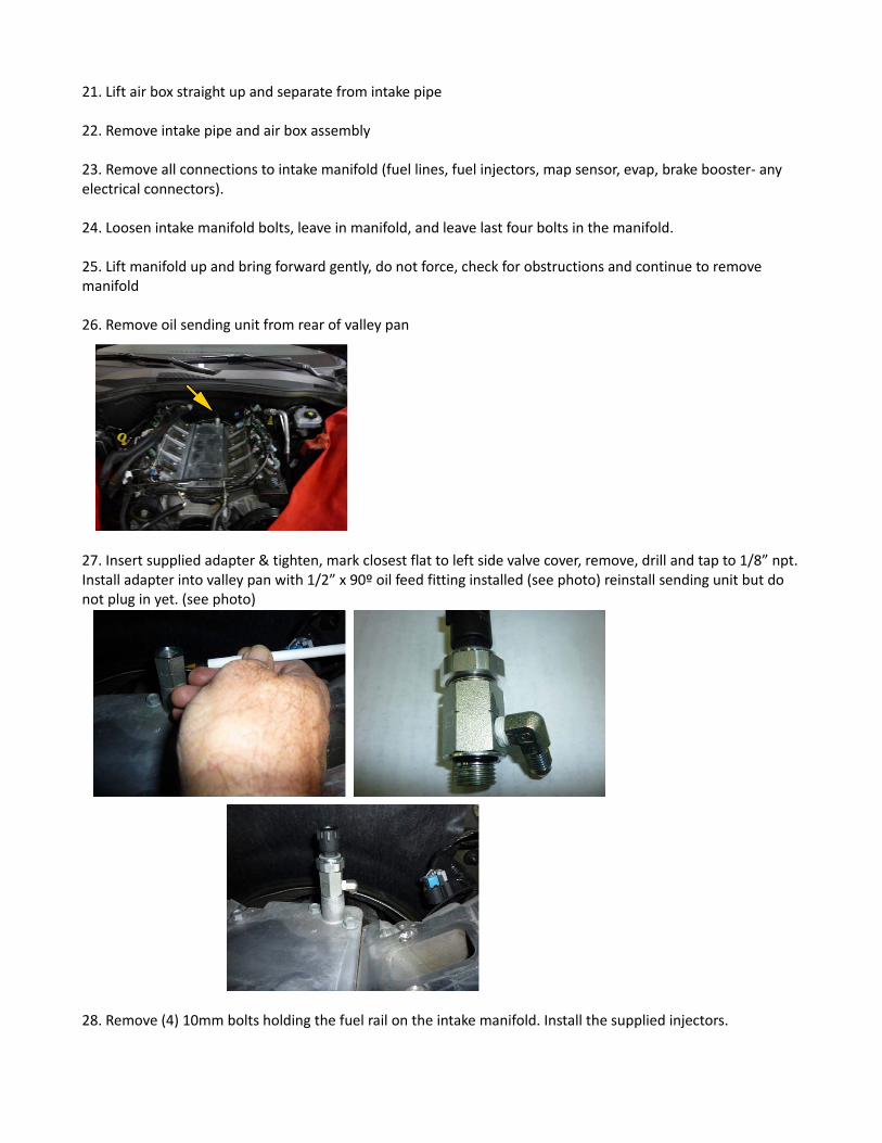
13. Remove washer bottle (this will not be reused but supplied with a replacement)
14. Remove rear O2 sensors and unbolt exhaust flanges at the manifolds.
15. Remove floor brace
16. Remove exhaust mid pipes
17. Intake Removal: Disconnect and remove mass air flow sensor, save for reinstall.
18. Remove 2 nuts holding air box assembly
19. Loosen 2 clamps holding intake pipe
20. Remove crankcase vent pipe from intake pipe and valve cover, install supplied rubber plug onto valve cover nipple using supplied clamp.
21. Lift air box straight up and separate from intake pipe
22. Remove intake pipe and air box assembly
23. Remove all connections to intake manifold (fuel lines, fuel injectors, map sensor, evap, brake booster- any electrical connectors).
24. Loosen intake manifold bolts, leave in manifold, and leave last four bolts in the manifold.
25. Lift manifold up and bring forward gently, do not force, check for obstructions and continue to remove manifold
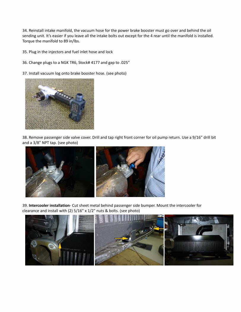
26. Remove oil sending unit from rear of valley pan
27. Insert supplied adapter & tighten, mark closest flat to left side valve cover, remove, drill and tap to 1/8” npt. Install adapter into valley pan with 1/2” x 90º oil feed fitting installed (see photo) reinstall sending unit but do not plug in yet. (see photo)
28. Remove (4) 10mm bolts holding the fuel rail on the intake manifold. Install the supplied injectors.

29. Install -3AN oil feed hose onto 90º fitting installed in step 27. Be sure tee is flat and the hose with the heat protector sleeve goes towards the right side. (see photo)
30. Locate the left side (driver’s side) turbo assembly. Install front O2 sensor after removing it from the OEM converter assembly.
31. Install OEM manifold to converter gaskets onto left side turbo assembly. Install O2 extension harness from the rear of the heads and route it towards the downpipes. The turbo assembly installs from the bottom. Raise it to the exhaust manifold and slip the downpipe portion into the stock band clamps, holding the assembly in place. Start both nuts onto the exhaust manifold studs, align and torque to 35ft/lbs. Install oil feel supply line and tighten.
32. Like the left side, the right side (passenger side) reuses the OEM gasket, installs from the bottom, start oil feed once nuts are started on studs. Use the OEM exhaust band clamps to slide on to the turbo downpipe. Tighten the manifold to adapter nuts to 35ft/lbs. Plug in O2s and tighten oil feed on turbocharger. Secure the oil feed line to the turbo.
33. Installing oil drain assembly and hoses- the drains are shipped preassembled with the exception of the drain plates. You’ll need to install the drain hose onto the passenger oil drain plate first. Using the provided gaskets and bolts install the drivers side drain flange with the drain plate on the drain assembly first. The long –10AN hose goes forward. Be careful not to twist the lines while tightening. (see photo)
34. Reinstall intake manifold, the vacuum hose for the power brake booster must go over and behind the oil sending unit. It’s easier if you leave all the intake bolts out except for the 4 rear until the manifold is installed. Torque the manifold to 89 in/lbs.
35. Plug in the injectors and fuel inlet hose and lock
36. Change plugs to a NGK TR6, Stock# 4177 and gap to .025”
37. Install vacuum log onto brake booster hose. (see photo)
38. Remove passenger side valve cover. Drill and tap right front corner for oil pump return. Use a 9/16” drill bit and a 3/8” NPT tap. (see photo)
39. Intercooler installation- Cut sheet metal behind passenger side bumper. Mount the intercooler for clearance and install with (2) 5/16” x 1/2" nuts & bolts. (see photo)

40. Installation of scavenging pump- Using the oil pump bracket as a template. position oil pump and mark holes. Drill 1/4” and install with (2) 1/4" x 3/4" bolts, washers and nuts. (see photo)
41. Install -10AN hose from pump to forward fitting on drain tank (see photo)
42. Install -8AN hose to pump out to valve cover (see photo)
43. Drivers side intercooler hot side pipes- Install 2-1/2” elbow onto intercooler with (2) #40 clamps. (see photo)
44. Install 2” x 2-1/4” coupler onto driver’s side turbo with (2) #36 clamps. (see photo)
45. This picture is for reference only. Follow the directions taped to intercooler ducting.

46. Install 2” pipe # from top onto turbo coupler. (see photo)
47. Install 2-1/2” pipe # onto intercooler and through to inside of frame. (see photo)
48. Install 2-1/2” to 2” hose coupler onto both pipes and tighten (6) clamps. (see photo)
49. Note w/g inlet different for M6
50. Passenger side intercooler ducting hot side- install 2-1/2” elbow onto intercooler; short leg to intercooler side. (see photo)
51. Install 2” x 2-1/4” hose onto 2” pipe #? turbo side of pipe. (see photo)
52. Install 2” pipe # through outer wheel well and align with turbo. Some slight bending of the a/c lines may be necessary. (see photo)
53. Slide 2” coupler off of pipe onto turbo pipe. It should be pointing straight forward between AC hoses and frame rail. (see photo)
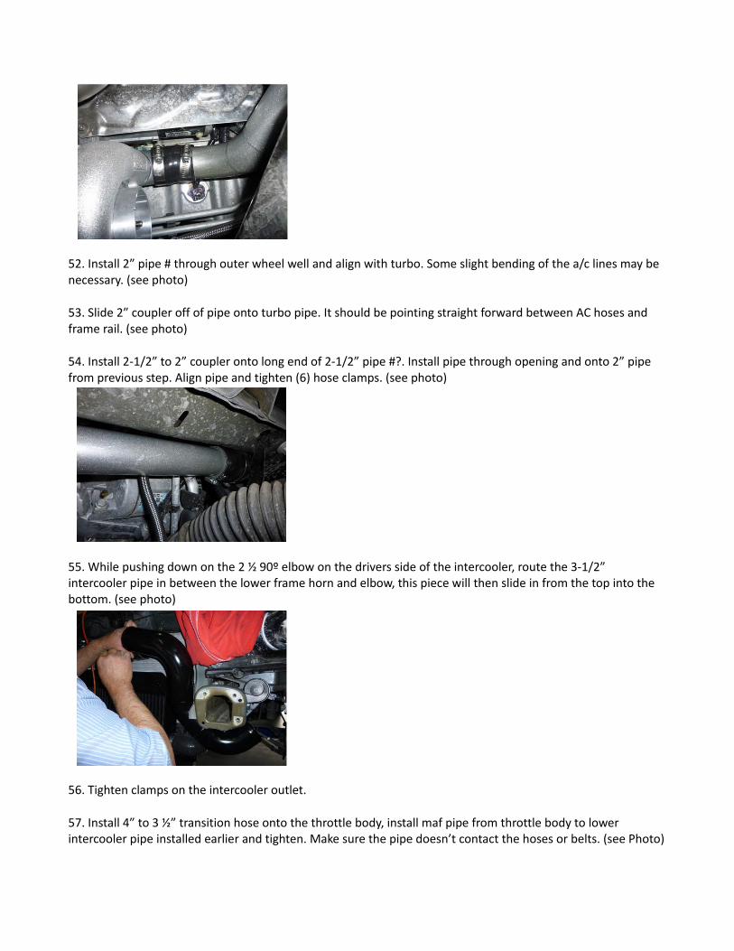
54. Install 2-1/2” to 2” coupler onto long end of 2-1/2” pipe #?. Install pipe through opening and onto 2” pipe from previous step. Align pipe and tighten (6) hose clamps. (see photo)
55. While pushing down on the 2 ½ 90º elbow on the drivers side of the intercooler, route the 3-1/2” intercooler pipe in between the lower frame horn and elbow, this piece will then slide in from the top into the bottom. (see photo)
56. Tighten clamps on the intercooler outlet.
57. Install 4” to 3 ½” transition hose onto the throttle body, install maf pipe from throttle body to lower intercooler pipe installed earlier and tighten. Make sure the pipe doesn’t contact the hoses or belts. (see Photo)
58. Install maf sensor and BOV.
59. Slide silicone elbow on other end of pipe previously installed. (see photo)
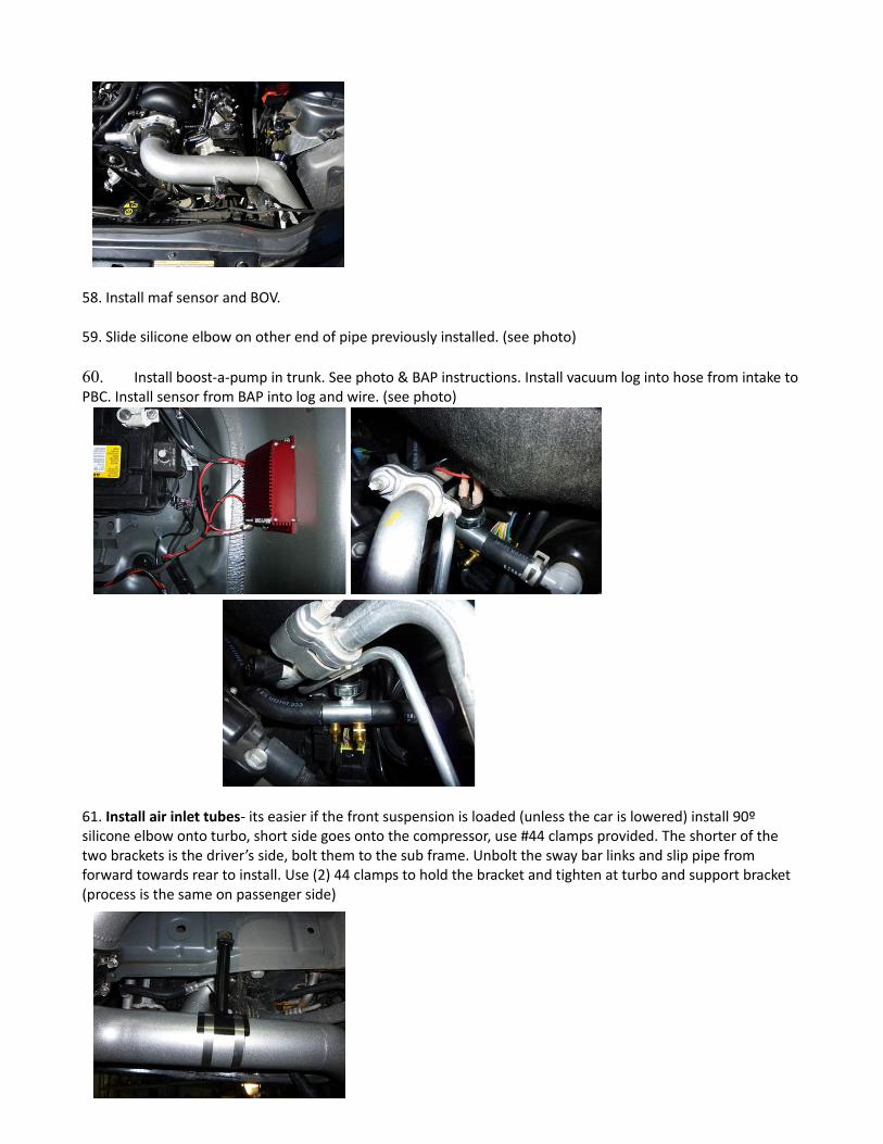
60. Install boost-a-pump in trunk. See photo & BAP instructions. Install vacuum log into hose from intake to PBC. Install sensor from BAP into log and wire. (see photo)
61. Install air inlet tubes- its easier if the front suspension is loaded (unless the car is lowered) install 90º silicone elbow onto turbo, short side goes onto the compressor, use #44 clamps provided. The shorter of the two brackets is the driver’s side, bolt them to the sub frame. Unbolt the sway bar links and slip pipe from forward towards rear to install. Use (2) 44 clamps to hold the bracket and tighten at turbo and support bracket (process is the same on passenger side)

62. Install K&N air filter. (see photo)
63. Same process as right side
64. Reinstall sway bar using spacers provided. We recommend grinding or cutting the remaining stud after tightening the sway bar links, they’ll rub on the inlet pipes if you don’t. (see photo)
65. Plug in air temp sensor and reinstall front bumper cover. (see photo)
66. Reinstall front end, some adjustment of air filters will be necessary.
67. Wiring of oil pump relay- use IGN FUSE#19 (GREEN) 20amp and #85 BLUE (ground; see step 68).
68. Red goes to battery 12V+

69. Light blue from relay to ground (-)
70. Yellow to pump positive (+)
71. Black from oil pump to ground (-) (same as step 68)
72. Run boost hose from log to brass tee and then to w/g, if an aftermarket boost controller is added, follow instructions provided with that gate.
73. Install supplied check valve from intake to valley pan nipple. Arrow goes towards intake. Gently tighten the clamp on the intake side, remember, its plastic (see photo)
74. Install supplied vented oil filler cap.
75. Once you’re all finished and ready to start it for the first time, take a moment to double check a few things- make sure the transmission cooler lines aren’t touching the wastegate dump tube on the passenger side and also check the steel braided oil return line to the oil pump isn’t touching the trans cooler lines either.
76. If you want but isn’t necessary you can trim the lower corners of each plastic wheel well liner so they lay fat. (see photo)

77. Reconnect battery.
78. If your kit was purchased with the optional flash tune flash it at this time. Check for leaks and be sure the oil pump is working and there are no exhaust leaks.
LIMITED WARRANTY& LIABILITY AGREEMENT
Granatelli Motor Sports warrants that all products shall be free from defects in materials and/or workmanship for90 days from the date of purchase (except in-tank and in-line fuel pumps purchased at dealer or wd prices asthese items have no warranty). The following requirements and exclusions apply: (1) You must be the originalpurchaser and must complete the warranty registration form (located atwww.GranatelliMotorSports.com/warranty.asp) and return the defective product within 10 days of your originalpurchase. Failure to do so voids all warranty, either express or implied set forth herein. (2) You must reside inthe United States or Canada and use the product as described in the warranty registration. (3) The product mustnot have been altered, disassembled, modified, or converted for any other use than intended by Granatelli MotorSports. (4) The product, or any part thereof, is not used in accordance with the operating parameters specified byGranatelli Motor Sports (5) The product or any part thereof is damaged or rendered unserviceable due tonegligence, vandalism, theft, fire, debris, flood, Act of God, or other peril, malfunction of equipment, or by anycause within the Customer's control. (6) The serial number (if applicable) must not have been altered orremoved. The extent of Granatelli Motor Sports' liability under this warranty shall be limited to the promptcorrection or replacement, at Granatelli Motor Sports' option and at no cost to the customer other than returnshipment, of any defective part of the product determined to be necessary by Granatelli Motor Sports. This onlyapplies if a written notice of the claimed defect was received by Granatelli Motor Sports prior to expiration of thewarranty period. All warranties of merchantability and fitness for a particular purpose are expressly excluded. Theduration of any and all implied warranties is limited to the duration of this express warranty. All incidental andconsequential damages including but not limited to loss profits even if it has been advised of the possibility ofsuch damages are hereby excluded. Regardless of the form of the claim, Granatelli Motor Sports liability for anydamages to the customer for such product is limited to the guidelines herein. This stated, expressed warranty isin lieu of all liabilities or obligations of Granatelli Motor Sports for damages arising out of or in connection withdelivery, use or performance of the product. This warranty cannot be amended or changed by any GranatelliMotor Sports representative, employee, or agent and any promises inconsistent with this warranty are void andunenforceable against Granatelli Motor Sports. Some states do not allow limitations of incidental orconsequential damages, so the above limitations or exclusions may not apply to you. This warranty gives youspecific legal rights and you may have other rights that vary from state to state. Your sole remedy for the abovewarranties is the repair or replacement of the defective product only, at Granatelli Motor Sports’ sole discretion.
RETURN POLICY:
NOTE: No returns accepted without pre-approved RGA (return goods authorization) number clearly marked onthe outside of the box. No returns accepted on special orders or after 90 days from date of original shipment. Allreturns are subject to a 25% restocking fee. Before you return this product, contact our service department M-F8AM-5PM (PST) at 805-486-6644, Ext. 23 or [email protected] for an RGA number.Returns made without prior authorization will be refused. All returns must be made within 30 days from date oforiginal shipment, safety packaged in original packaging (if available as in-transit damage is not covered by our

limited warranty), have the RGA number clearly marked on the top and two sides of the box and be insured for fullreplacement value. We recommend using UPS or the UPS Store for shipping. In-bound freight is alwayscustomer's responsibility. All returns are subject to a restocking fee up to 25%. The balance will be returned in theform of a check or may be applied as credit towards another purchase. Special orders and electrical componentsare not eligible for returns. For warranty registration, go to: www.GranatelliMotorSports.com/warranty.asp.PERFORMANCE CONSUMER'S BILL OF RIGHTS:Legally, a vehicle manufacturer cannot void the warranty on a vehicle due to an aftermarket part unless they canprove that the aftermarket part caused or contributed to the failure in the vehicle (per the Magnuson MossWarranty Act, www.GranatelliMotorSports.com/magnusonmoss.htm (15 U.S.C. 2302(C)) . For best results,consider working with performance-oriented dealerships with a proven history of working with customers. If yourvehicle manufacturer fails to honor emission/warranty claims, contact EPA at (202) 260-2080 or www.epa.gov. Iffederal warranty protection is denied, contact the FTC at (202) 326-3128 or www.ftc.gov.