gem-tpc trackers for the super-frs at fair
TRANSCRIPT
GEM-TPC TRACKERS FOR THE SUPER-FRS AT FAIR
M. Kalliokoski*, F. Garcia, A. Numminen, R. Lauhakangas, E. Tuominen, Helsinki Institute of Physics, Helsinki, Finland
R. Janik, M. Pikna, B. Sitar, P. Strmen, I. Szarka, FMPI, Comenius University, Bratislava, Slovakia
Abstract For the slow extraction part of the beam diagnostics
system of the Superconducting Projectile Fragment Separator (Super-FRS) [1] of FAIR-facility a total of 32 detectors are needed. They will be used for beam monitoring, tracking and characterization of the produced ions. GEM-TPC detectors can perform over wide dynamic range without disturbing the beam and are thus suitable for this kind of in-beam detection. We present the simulations and first measurements with the GEMs of the Super-FRS GEM-TPC prototype.
INTRODUCTION The Facility for Antiproton and Ion Research (FAIR)
[2] will be built as an extension of the current GSI facility in Darmstadt, Germany. Nuclear Structure, Astrophysics and Reactions (NuSTAR) [3] collaboration will develop, construct and operate the Super-FRS rare isotope beam facility and the related experiments at future FAIR.
The Super-FRS separator will be optimized to an efficient in-flight separation of all primary beams up to 238U and via fission of 238U beams. A diagram of the Super-FRS is shown in Figure 1. It will have two independent separator stages, the Pre and the Main. The Main-Separator stage will be divided into three branches connecting different experimental areas.
Figure 1: Layout of the Superconducting Fragment Separator Super-FRS.
Beam diagnostics system to be used commonly by the
experiments will be an important part of the Super-FRS. The main tasks of the system will be to adjust the separator and to perform beam monitoring, particle identification, tracking and characterization of produced ions.
The beam diagnostics systems will be installed in all intermediate foci with an active area of (40x20) cm2. The
slow extraction with extraction times above 100 ms can be done with GEM-TPC detectors [4].
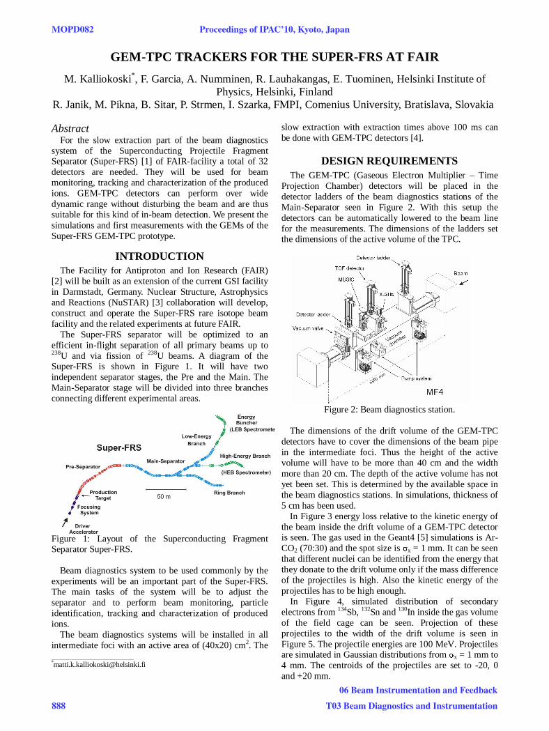
DESIGN REQUIREMENTS The GEM-TPC (Gaseous Electron Multiplier – Time
Projection Chamber) detectors will be placed in the detector ladders of the beam diagnostics stations of the Main-Separator seen in Figure 2. With this setup the detectors can be automatically lowered to the beam line for the measurements. The dimensions of the ladders set the dimensions of the active volume of the TPC.
Figure 2: Beam diagnostics station.
The dimensions of the drift volume of the GEM-TPC
detectors have to cover the dimensions of the beam pipe in the intermediate foci. Thus the height of the active volume will have to be more than 40 cm and the width more than 20 cm. The depth of the active volume has not yet been set. This is determined by the available space in the beam diagnostics stations. In simulations, thickness of 5 cm has been used.
In Figure 3 energy loss relative to the kinetic energy of the beam inside the drift volume of a GEM-TPC detector is seen. The gas used in the Geant4 [5] simulations is Ar-CO2 (70:30) and the spot size is σx = 1 mm. It can be seen that different nuclei can be identified from the energy that they donate to the drift volume only if the mass difference of the projectiles is high. Also the kinetic energy of the projectiles has to be high enough.
In Figure 4, simulated distribution of secondary electrons from 134Sb, 132Sn and 130In inside the gas volume of the field cage can be seen. Projection of these projectiles to the width of the drift volume is seen in Figure 5. The projectile energies are 100 MeV. Projectiles are simulated in Gaussian distributions from σx = 1 mm to 4 mm. The centroids of the projectiles are set to -20, 0 and +20 mm.
_________________________________________ *[email protected]
MOPD082 Proceedings of IPAC’10, Kyoto, Japan
888
06 Beam Instrumentation and Feedback
T03 Beam Diagnostics and Instrumentation
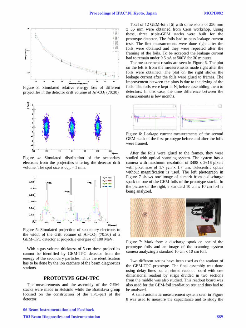
Figure 3: Simulated relative energy loss of different projectiles in the detector drift volume of Ar-CO2 (70:30).
Figure 4: Simulated distribution of the secondary electrons from the projectiles entering the detector drift volume. The spot size is σx, y = 1 mm.
Figure 5: Simulated projection of secondary electrons to the width of the drift volume of Ar-CO2 (70:30) of a GEM-TPC detector at projectile energies of 100 MeV.
With a gas volume thickness of 5 cm these projectiles
cannot be identified by GEM-TPC detector from the energy of the secondary particles. Thus the identification has to be done by the ion catchers of the beam diagnostics stations.
PROTOTYPE GEM-TPC The measurements and the assembly of the GEM-
stacks were made in Helsinki while the Bratislava group focused on the construction of the TPC-part of the detector.
Total of 12 GEM-foils [6] with dimensions of 256 mm x 56 mm were obtained from Cern workshop. Using these, three triple-GEM stacks were built for the prototype detector. The foils had to pass leakage current tests. The first measurements were done right after the foils were obtained and they were repeated after the framing of the foils. To be accepted the leakage current had to remain under 0.5 nA at 500V for 30 minutes.
The measurement results are seen in Figure 6. The plot on the left is from the measurements made right after the foils were obtained. The plot on the right shows the leakage current after the foils were glued to frames. The improvement between the plots is due to the drying of the foils. The foils were kept in N2 before assembling them to detectors. In this case, the time difference between the measurements is few months.
Figure 6: Leakage current measurements of the second GEM-stack of the first prototype before and after the foils were framed.
After the foils were glued to the frames, they were studied with optical scanning system. The system has a camera with maximum resolution of 3488 x 2616 pixels with pixel size of 1.7 μm x 1.7 μm. Telecentric optics without magnification is used. The left photograph in Figure 7 shows one image of a mark from a discharge spark on one of the GEM-foils of the prototype stacks. In the picture on the right, a standard 10 cm x 10 cm foil is being analyzed.
Figure 7: Mark from a discharge spark on one of the prototype foils and an image of the scanning system camera analyzing a standard 10 cm x 10 cm foil.
Two different setups have been used as the readout of the GEM-TPC prototype. The final assembly was done using delay lines but a printed readout board with one dimensional readout by strips divided in two sections from the middle was also studied. This readout board was also used for the GEM-foil irradiation test and thus had to be analyzed.
A semi-automatic measurement system seen in Figure 8 was used to measure the capacitance and to study the
Proceedings of IPAC’10, Kyoto, Japan MOPD082
06 Beam Instrumentation and Feedback
T03 Beam Diagnostics and Instrumentation 889

contacts of the 130-pin Panasonic connectors. The average capacitance was measured to be 3.9 pF for the longer and 3.6 pF for the shorter strips of the board.
Figure 8: The semi-automatic measurement setup of the capacitances of readout-boards and the measured average values of the capacitances of the prototype readout. The connectors are positioned in two rows giving different capacitances to different sides.
The GEM-stack was powered by resistive voltage divider. The active detector volume for the testing of the stacks was composed of a 3 mm drift region, followed by three foils with gaps of 2 mm each. Drift foil was made from one sided alumina coated Mylar foil. The stacks were irradiated with 5.9 keV X-rays from 55Fe source. Figure 9 shows a photograph of the measurement container. The foils were put in a container with a flow of Ar-CO2 (70:30) at room temperature in standard pressure.
Figure 9: Measurement setup of the GEM-stacks. An average resolution FWHME/E = 24.5713 ± 0.2154%
was measured over the detector length. The GEM-stack was set with VGEM1 = 400 V, VGEM2 = 360 V, VGEM3 = 320 V, Vtrans1 = Vtrans2 = Vind = 710 V. Drift field was set to Edrift = 2.376 kV/cm. A spectrum from one measurement is seen in Figure 10.
Figure 10: Measured 55Fe spectra with energy resolution ΔE = 24.3437 ± 0.1612 % at Ar-CO2 (70:30).
The sensitive volume of the field cage of the prototype is 256 mm x 56 mm x 100 mm. The uniform electric field inside the TPC drift volume is formed by high-voltage cathode plane and field forming Mylar strips. Figure 11 shows a photograph of one of the field cages built in Bratislava.
Figure 11: Field cage design of the prototype.
The assembly of the first prototype was made in
Bratislava. Figure 12 shows an image of the detector on test bench at Bratislava.
Figure 12: Assembled GEM-TPC detector in vacuum chamber in laboratory measurements.
CONCLUSIONS A prototype GEM-TPC detector has been build and the
tests of the components have been performed. All the parts used in the prototype have been tested and found to be suitable for the full performance tests of the prototype with test beams in Cern and at GSI. Detailed analysis of the performance of the prototype will be done after the tests.
REFERENCES [1] H. Geissel et al., “Technical Design Report on the
Super FRS”, March 2008. [2] G. Rosner, Nucl. Phys. B – Proceedings
Supplements, vol. 167, May 2007, p. 77. [3] http://www.gsi.de/fair/experiments/NUSTAR [4] M. Killenberg et al., Nucl. Instr. and Meth. A 498
(2003) p.369. [5] S. Agostinelli et al., Nucl. Instr. and Meth. A 506
(2003), p. 250. [6] F.Sauli, Nucl. Instr. and Meth. A 386 (1997), p.53
MOPD082 Proceedings of IPAC’10, Kyoto, Japan
890
06 Beam Instrumentation and Feedback
T03 Beam Diagnostics and Instrumentation