geckoflex frames 8900f signal processing system instruction
TRANSCRIPT

GeckoFlex Frames8900FX/FF/FFN SIGNAL PROCESSING SYSTEM
Instruction Manual
071844404JULY 2010

Affiliate with the N.V. KEMA in The Netherlands
CERTIFICATECertificate Number: 510040.001 The Quality System of: Thomson Inc, and it’s wordwide Grass Valley division affiliates DBA GRASS VALLEY
Headquarters 400 Providence Mine Rd Nevada City, CA 95959 United States
15655 SW Greystone Ct. Beaverton, OR 97006 United States
10 Presidential Way Suite 300 Woburn, MA 01801 United States
Kapittelweg 10 4827 HG Breda The Nederlands
7140 Baymeadows Way Ste 101 Jacksonville, FL 32256 United States
2300 So. Decker Lake Blvd. Salt Lake City, UT 84119 United States
Rue du Clos Courtel CS 31719 35517 Cesson-Sevigné Cedex France
1 rue de l’Hautil Z.I. des Boutries BP 150 78702 Conflans-Sainte Honorine Cedex France
Technopole Brest-Iroise Site de la Pointe du Diable CS 73808 29238 Brest Cedex 3 France
40 Rue de Bray 2 Rue des Landelles 35510 Cesson Sevigné France
Spinnereistrasse 5 CH-5300 Turgi Switzerland
Brunnenweg 9 D-64331 Weiterstadt Germany
Carl-Benz-Strasse 6-8 67105 Schifferstadt Germany
Including its implementation, meets the requirements of the standard:
ISO 9001:2008 Scope:The design, manufacture and support of video and audio hardware and software products and related systems.
This Certificate is valid until: June 14, 2012 This Certificate is valid as of: June 14, 2009 Certified for the first time: June 14, 2000
H. Pierre Sallé President KEMA-Registered Quality
The method of operation for quality certification is defined in the KEMA General Terms And Conditions For Quality And Environmental Management Systems Certifications. Integral publication of this certificate is allowed.
KEMA-Registered Quality, Inc.4377 County Line Road Chalfont, PA 18914 Ph: (215)997-4519 Fax: (215)997-3809 CRT 001 073004
Accredited By:ANAB

GeckoFlex Frames8900FX/FF/FFN SIGNAL PROCESSING SYSTEM
Instruction Manual
071844404JULY 2010

4 GeckoFlex Frames — Instruction Manual
Contacting Grass Valley
Copyright © Grass Valley, Inc. All rights reserved.This product may be covered by one or more U.S. and foreign patents.
Grass Valley Web Site The www.grassvalley.com web site offers the following:
Online User Documentation — Current versions of product catalogs, brochures, data sheets, ordering guides, planning guides, manuals, and release notes in .pdf format can be downloaded.
FAQ Database — Solutions to problems and troubleshooting efforts can be found by searching our Frequently Asked Questions (FAQ) database.
Software Downloads — Download software updates, drivers, and patches.
InternationalSupport Centers
France24 x 7 +800 8080 2020 or +33 1 48 25 20 20 United States/Canada
24 x 7 +1 800 547 8949 or +1 530 478 4148
Local Support Centers
(available during normal
business hours)
AsiaHong Kong, Taiwan, Korea, Macau: +852 2531 3058 Indian Subcontinent: +91 22 24933476Southeast Asia/Malaysia: +603 7805 3884 Southeast Asia/Singapore: +65 6379 1313China: +861 0660 159 450 Japan: +81 3 5484 6868
Australia and New Zealand: +61 1300 721 495 Central/South America: +55 11 5509 3443
Middle East: +971 4 299 64 40 Near East and Africa: +800 8080 2020 or +33 1 48 25 20 20
Europe
Belarus, Russia, Tadzikistan, Ukraine, Uzbekistan: +7 095 2580924 225 Switzerland: +41 1 487 80 02S. Europe/Italy-Roma: +39 06 87 20 35 28 -Milan: +39 02 48 41 46 58 S. Europe/Spain: +34 91 512 03 50Benelux/Belgium: +32 (0) 2 334 90 30 Benelux/Netherlands: +31 (0) 35 62 38 42 1 N. Europe: +45 45 96 88 70Germany, Austria, Eastern Europe: +49 6150 104 444 UK, Ireland, Israel: +44 118 923 0499

ContentsPreface. . . . . . . . . . . . . . . . . . . . . . . . . . . . . . . . . . . . . . . . . . . . . . . . . . . . . . . . . . . . . . . . . . . . . 9
About This Manual . . . . . . . . . . . . . . . . . . . . . . . . . . . . . . . . . . . . . . . . . . . . . . . . . . . . . 9
Safety Summary. . . . . . . . . . . . . . . . . . . . . . . . . . . . . . . . . . . . . . . . . . . . . . . . . . . . . . . . . 11Safety Terms and Symbols. . . . . . . . . . . . . . . . . . . . . . . . . . . . . . . . . . . . . . . . . . . . . . 11
Terms in This Manual . . . . . . . . . . . . . . . . . . . . . . . . . . . . . . . . . . . . . . . . . . . . . . . . 11Terms on the Product . . . . . . . . . . . . . . . . . . . . . . . . . . . . . . . . . . . . . . . . . . . . . . . . 11Symbols on the Product . . . . . . . . . . . . . . . . . . . . . . . . . . . . . . . . . . . . . . . . . . . . . . 12
Warnings . . . . . . . . . . . . . . . . . . . . . . . . . . . . . . . . . . . . . . . . . . . . . . . . . . . . . . . . . . . . 12Cautions . . . . . . . . . . . . . . . . . . . . . . . . . . . . . . . . . . . . . . . . . . . . . . . . . . . . . . . . . . . . . 13
Sicherheit – Überblick . . . . . . . . . . . . . . . . . . . . . . . . . . . . . . . . . . . . . . . . . . . . . . . . . . 15
Consignes de sécurité . . . . . . . . . . . . . . . . . . . . . . . . . . . . . . . . . . . . . . . . . . . . . . . . . . . 19
Regulatory Notices . . . . . . . . . . . . . . . . . . . . . . . . . . . . . . . . . . . . . . . . . . . . . . . . . . . . . . 23Certifications and Compliances . . . . . . . . . . . . . . . . . . . . . . . . . . . . . . . . . . . . . . . . . 23
FCC Emission Control . . . . . . . . . . . . . . . . . . . . . . . . . . . . . . . . . . . . . . . . . . . . . . . 23Canadian EMC Notice of Compliance . . . . . . . . . . . . . . . . . . . . . . . . . . . . . . . . . . 23EN55022 Class A Warning . . . . . . . . . . . . . . . . . . . . . . . . . . . . . . . . . . . . . . . . . . . . 23Canadian Certified Power Cords . . . . . . . . . . . . . . . . . . . . . . . . . . . . . . . . . . . . . . 24Canadian Certified AC Adapter . . . . . . . . . . . . . . . . . . . . . . . . . . . . . . . . . . . . . . . 24Laser Compliance . . . . . . . . . . . . . . . . . . . . . . . . . . . . . . . . . . . . . . . . . . . . . . . . . . . 24
Laser Safety Requirements . . . . . . . . . . . . . . . . . . . . . . . . . . . . . . . . . . . . . . . . . . 24Laser Safety . . . . . . . . . . . . . . . . . . . . . . . . . . . . . . . . . . . . . . . . . . . . . . . . . . . . . . . 24FCC Emission Limits . . . . . . . . . . . . . . . . . . . . . . . . . . . . . . . . . . . . . . . . . . . . . . . 25
Certifications . . . . . . . . . . . . . . . . . . . . . . . . . . . . . . . . . . . . . . . . . . . . . . . . . . . . . . . . . 25
ESD Protection . . . . . . . . . . . . . . . . . . . . . . . . . . . . . . . . . . . . . . . . . . . . . . . . . . . . . . . . . . 27Recommended ESD Guidelines . . . . . . . . . . . . . . . . . . . . . . . . . . . . . . . . . . . . . . . . . 27Sources of ESD and Risks. . . . . . . . . . . . . . . . . . . . . . . . . . . . . . . . . . . . . . . . . . . . . . . 28Grounding Requirements for Personnel . . . . . . . . . . . . . . . . . . . . . . . . . . . . . . . . . . 29
Section 1 — GeckoFlex Frames . . . . . . . . . . . . . . . . . . . . . . . . . . . . . . . . . . . . . . . . 31Introduction . . . . . . . . . . . . . . . . . . . . . . . . . . . . . . . . . . . . . . . . . . . . . . . . . . . . . . . . . . 31GeckoFlex Frames Types . . . . . . . . . . . . . . . . . . . . . . . . . . . . . . . . . . . . . . . . . . . . . . . 33
8900FX – Basic GeckoFlex Distribution Frame . . . . . . . . . . . . . . . . . . . . . . . . . . . 338900FF – Fan-Cooled GeckoFlex Frame . . . . . . . . . . . . . . . . . . . . . . . . . . . . . . . . . 348900FFN – High-Power GeckoFlex Frame. . . . . . . . . . . . . . . . . . . . . . . . . . . . . . . 34Frame Options . . . . . . . . . . . . . . . . . . . . . . . . . . . . . . . . . . . . . . . . . . . . . . . . . . . . . . 35Frame Upgrades . . . . . . . . . . . . . . . . . . . . . . . . . . . . . . . . . . . . . . . . . . . . . . . . . . . . 35
Frame Capacity . . . . . . . . . . . . . . . . . . . . . . . . . . . . . . . . . . . . . . . . . . . . . . . . . . . . . . . 36Calculating Frame Power . . . . . . . . . . . . . . . . . . . . . . . . . . . . . . . . . . . . . . . . . . . . . 36
Power Supply/Demand Web Page (8900FFN Frames) . . . . . . . . . . . . . . . . . . 36
GeckoFlex Frames — Instruction Manual 5

Contents
Section 2 — Installation . . . . . . . . . . . . . . . . . . . . . . . . . . . . . . . . . . . . . . . . . . . . . . . . 41Introduction. . . . . . . . . . . . . . . . . . . . . . . . . . . . . . . . . . . . . . . . . . . . . . . . . . . . . . . . . . 41Rack Mounting the Frame. . . . . . . . . . . . . . . . . . . . . . . . . . . . . . . . . . . . . . . . . . . . . . 42
Rear Rack Support Option. . . . . . . . . . . . . . . . . . . . . . . . . . . . . . . . . . . . . . . . . . . . 42Ventilation Restrictions . . . . . . . . . . . . . . . . . . . . . . . . . . . . . . . . . . . . . . . . . . . . . . 438900-FRMKIT Installation . . . . . . . . . . . . . . . . . . . . . . . . . . . . . . . . . . . . . . . . . . . . 44Frame Front Cover . . . . . . . . . . . . . . . . . . . . . . . . . . . . . . . . . . . . . . . . . . . . . . . . . . 46Power Supply Installation . . . . . . . . . . . . . . . . . . . . . . . . . . . . . . . . . . . . . . . . . . . . 47
Power Supply Descriptions . . . . . . . . . . . . . . . . . . . . . . . . . . . . . . . . . . . . . . . . . 48Module Installation . . . . . . . . . . . . . . . . . . . . . . . . . . . . . . . . . . . . . . . . . . . . . . . . . . . 49
Module Installation Precautions . . . . . . . . . . . . . . . . . . . . . . . . . . . . . . . . . . . . . 49Fiber Optic Cleaning Requirement. . . . . . . . . . . . . . . . . . . . . . . . . . . . . . . . . . . 50
Frame Monitor and 8900NET (Net Card) Network Interface Modules . . . . . . 50Module Placement for Genlock Timing Buses . . . . . . . . . . . . . . . . . . . . . . . . . . . 51Rear Module Installation . . . . . . . . . . . . . . . . . . . . . . . . . . . . . . . . . . . . . . . . . . . . . 52
Blank Rear Adapter Covers . . . . . . . . . . . . . . . . . . . . . . . . . . . . . . . . . . . . . . . . . 52Submodule Installation . . . . . . . . . . . . . . . . . . . . . . . . . . . . . . . . . . . . . . . . . . . . . . 54
Genlock Submodules . . . . . . . . . . . . . . . . . . . . . . . . . . . . . . . . . . . . . . . . . . . . . . 54SFP Fiber Optic Submodules . . . . . . . . . . . . . . . . . . . . . . . . . . . . . . . . . . . . . . . . 54
Front Module Installation . . . . . . . . . . . . . . . . . . . . . . . . . . . . . . . . . . . . . . . . . . . . 55Frame Connections. . . . . . . . . . . . . . . . . . . . . . . . . . . . . . . . . . . . . . . . . . . . . . . . . . . . 56
Frame Alarm Connector . . . . . . . . . . . . . . . . . . . . . . . . . . . . . . . . . . . . . . . . . . . . . 58Frame Alarm Conditions . . . . . . . . . . . . . . . . . . . . . . . . . . . . . . . . . . . . . . . . . . . 58Frame Alarm Example . . . . . . . . . . . . . . . . . . . . . . . . . . . . . . . . . . . . . . . . . . . . . 59
Module Cabling . . . . . . . . . . . . . . . . . . . . . . . . . . . . . . . . . . . . . . . . . . . . . . . . . . . . 60Loop-through Input Connectors. . . . . . . . . . . . . . . . . . . . . . . . . . . . . . . . . . . . . 60Video and Audio Input/Output Connections . . . . . . . . . . . . . . . . . . . . . . . . . 61
Section 3 — Power Up . . . . . . . . . . . . . . . . . . . . . . . . . . . . . . . . . . . . . . . . . . . . . . . . . . 63Introduction. . . . . . . . . . . . . . . . . . . . . . . . . . . . . . . . . . . . . . . . . . . . . . . . . . . . . . . . . . 63Power Connections . . . . . . . . . . . . . . . . . . . . . . . . . . . . . . . . . . . . . . . . . . . . . . . . . . . 63
Canadian Certified Power Cords . . . . . . . . . . . . . . . . . . . . . . . . . . . . . . . . . . . . . . 65Canadian Certified AC Adapter. . . . . . . . . . . . . . . . . . . . . . . . . . . . . . . . . . . . . . . 65Line Cord Retainer . . . . . . . . . . . . . . . . . . . . . . . . . . . . . . . . . . . . . . . . . . . . . . . . . . 65
Applying Power . . . . . . . . . . . . . . . . . . . . . . . . . . . . . . . . . . . . . . . . . . . . . . . . . . . . . . 66Verify Power Supply Demand . . . . . . . . . . . . . . . . . . . . . . . . . . . . . . . . . . . . . . . . 66
Section 4 — Monitoring and Control . . . . . . . . . . . . . . . . . . . . . . . . . . . . . . . . . . . 69Introduction. . . . . . . . . . . . . . . . . . . . . . . . . . . . . . . . . . . . . . . . . . . . . . . . . . . . . . . . . . 69Frame Monitor Module . . . . . . . . . . . . . . . . . . . . . . . . . . . . . . . . . . . . . . . . . . . . . . . . 70
Enabling Alarms and Fan Speed Control Option . . . . . . . . . . . . . . . . . . . . . . . . 71Frame Monitor Module Indicator LEDs . . . . . . . . . . . . . . . . . . . . . . . . . . . . . . . . 71
Establishing 8900FFN Frame Network Identity . . . . . . . . . . . . . . . . . . . . . . . . . . . 72Frame RS-232 Serial Port . . . . . . . . . . . . . . . . . . . . . . . . . . . . . . . . . . . . . . . . . . . . . 72
RS-232 Communication Port Cable . . . . . . . . . . . . . . . . . . . . . . . . . . . . . . . . . . 72Ethernet Cable . . . . . . . . . . . . . . . . . . . . . . . . . . . . . . . . . . . . . . . . . . . . . . . . . . . . 74Local Area Network (LAN) Connection . . . . . . . . . . . . . . . . . . . . . . . . . . . . . . 75
Setting Frame Network Identity. . . . . . . . . . . . . . . . . . . . . . . . . . . . . . . . . . . . . . . 75NetConfig Application. . . . . . . . . . . . . . . . . . . . . . . . . . . . . . . . . . . . . . . . . . . . . . . 77
Connecting 8900FFN Frame to NetConfig LAN . . . . . . . . . . . . . . . . . . . . . . . 77
6 GeckoFlex Frames — Instruction Manual

Contents
Section 5 — Specifications . . . . . . . . . . . . . . . . . . . . . . . . . . . . . . . . . . . . . . . . . . . . . 81Introduction . . . . . . . . . . . . . . . . . . . . . . . . . . . . . . . . . . . . . . . . . . . . . . . . . . . . . . . . . . 81Frame Specifications . . . . . . . . . . . . . . . . . . . . . . . . . . . . . . . . . . . . . . . . . . . . . . . . . . . 81Power Supply. . . . . . . . . . . . . . . . . . . . . . . . . . . . . . . . . . . . . . . . . . . . . . . . . . . . . . . . . 83
Fiber Optic Submodules . . . . . . . . . . . . . . . . . . . . . . . . . . . . . . . . . . . . . . . . . . . . . . . . . 85Introduction . . . . . . . . . . . . . . . . . . . . . . . . . . . . . . . . . . . . . . . . . . . . . . . . . . . . . . . . . . 85
Index . . . . . . . . . . . . . . . . . . . . . . . . . . . . . . . . . . . . . . . . . . . . . . . . . . . . . . . . . . . . . . . . . . . . . . 89
GeckoFlex Frames — Instruction Manual 7

Contents
8 GeckoFlex Frames — Instruction Manual

Preface
About This ManualThis manual provides installation, safety and regulatory, power up, moni-toring and control, and specification information for the GeckoFlex frames (8900FX, 8900FF, and 8900FFN) for housing Grass Valley 8900 Series mod-ules.
This manual provides information for all versions of the GeckoFlex frames that have been shipped from the factory. Frame versions are identified by part number prefix (660- version and 751- version). The part number of the frame can be found on a label on the outside of the frame. Differences between frame versions are outlined throughout this manual when this information is pertinent.
The 8900NET (Net Card) software reflected in this manual is version 4.3.0.
All Modular product manuals can be found on-line in PDF format at this link:
wwwgrassvalley.com/docs/modular
GeckoFlex Frames — Instruction Manual 9

Preface
10 GeckoFlex Frames — Instruction Manual

Safety SummaryRead and follow the important safety information below, noting especially those instructions related to risk of fire, electric shock or injury to persons. Additional specific warnings not listed here may be found throughout the manual.
WARNING Any instructions in this manual that require opening the equipment cover or enclosure are for use by qualified service personnel only. To reduce the risk of electric shock, do not perform any servicing other than that con-tained in the operating instructions unless you are qualified to do so.
Safety Terms and Symbols
Terms in This ManualSafety-related statements may appear in this manual in the following form:
WARNING Warning statements identify conditions or practices that may result in per-sonal injury or loss of life.
CAUTION Caution statements identify conditions or practices that may result in damage to equipment or other property, or which may cause equipment crucial to your business environment to become temporarily non-operational.
Terms on the ProductThe following terms may appear on the product:
DANGER — A personal injury hazard is immediately accessible as you read the marking.
WARNING — A personal injury hazard exists but is not immediately acces-sible as you read the marking.
CAUTION — A hazard to property, product, and other equipment is present.
GeckoFlex Frames — Instruction Manual 11

Safety Summary
Symbols on the ProductThe following symbols may appear on the product:
Indicates that dangerous high voltage is present within the equipment enclosure that may be of sufficient magnitude to constitute a risk of electric shock.
Indicates that user, operator or service technician should refer to product manual(s) for important operating, maintenance, or service instructions.
This is a prompt to note fuse rating when replacing fuse(s). The fuse referenced in the text must be replaced with one having the ratings indicated.
Identifies a protective grounding terminal which must be con-nected to earth ground prior to making any other equipment connections.
Identifies an external protective grounding terminal which may be connected to earth ground as a supplement to an internal grounding terminal.
Indicates that static sensitive components are present which may be damaged by electrostatic discharge. Use anti-static procedures, equipment and surfaces during servicing.
WarningsThe following warning statements identify conditions or practices that can result in personal injury or loss of life:
Dangerous voltage or current may be present — Disconnect power and remove battery (if applicable) before removing protective panels, soldering, or replacing components.
Do not service alone — Do not internally service this product unless another person capable of rendering first aid and resuscitation is present.
Remove jewelry — Prior to servicing, remove jewelry such as rings, watches, and other metallic objects.
Avoid exposed circuitry — Do not touch exposed connections, components or circuitry when power is present.
12 GeckoFlex Frames — Instruction Manual

Safety Summary
Use proper power cord — Use only the power cord supplied or specified for this product.
Ground product — Connect the grounding conductor of the power cord to earth ground.
Operate only with covers and enclosure panels in place — Do not operate this product when covers or enclosure panels are removed.
Use correct fuse — Use only the fuse type and rating specified for this product.
Use only in dry environment — Do not operate in wet or damp conditions.
Use only in non-explosive environment — Do not operate this product in an explosive atmosphere.
High leakage current may be present — Earth connection of product is essential before connecting power.
Dual power supplies may be present — Be certain to plug each power supply cord into a separate branch circuit employing a separate service ground. Disconnect both power supply cords prior to servicing.
Double pole neutral fusing — Disconnect mains power prior to servicing.
Use proper lift points — Do not use door latches to lift or move equipment.
Avoid mechanical hazards — Allow all rotating devices to come to a stop before servicing.
CautionsThe following caution statements identify conditions or practices that can result in damage to equipment or other property:
Use correct power source — Do not operate this product from a power source that applies more than the voltage specified for the product.
Use correct voltage setting — If this product lacks auto-ranging power sup-plies, before applying power ensure that the each power supply is set to match the power source.
Provide proper ventilation — To prevent product overheating, provide equip-ment ventilation in accordance with installation instructions.
Use anti-static procedures — Static sensitive components are present which may be damaged by electrostatic discharge. Use anti-static procedures, equipment and surfaces during servicing.
Do not operate with suspected equipment failure — If you suspect product damage or equipment failure, have the equipment inspected by qualified service personnel.
GeckoFlex Frames — Instruction Manual 13

Safety Summary
Ensure mains disconnect — If mains switch is not provided, the power cord(s) of this equipment provide the means of disconnection. The socket outlet must be installed near the equipment and must be easily accessible. Verify that all mains power is disconnected before installing or removing power supplies and/or options.
Route cable properly — Route power cords and other cables so that they ar not likely to be damaged. Properly support heavy cable bundles to avoid con-nector damage.
Use correct power supply cords — Power cords for this equipment, if provided, meet all North American electrical codes. Operation of this equipment at voltages exceeding 130 VAC requires power supply cords which comply with NEMA configurations. International power cords, if provided, have the approval of the country of use.
Use correct replacement battery — This product may contain batteries. To reduce the risk of explosion, check polarity and replace only with the same or equivalent type recommended by manufacturer. Dispose of used bat-teries according to the manufacturer’s instructions.
Troubleshoot only to board level — Circuit boards in this product are densely populated with surface mount technology (SMT) components and applica-tion specific integrated circuits (ASICS). As a result, circuit board repair at the component level is very difficult in the field, if not impossible. For war-ranty compliance, do not troubleshoot systems beyond the board level.
14 GeckoFlex Frames — Instruction Manual

Safety Summary
Sicherheit – ÜberblickLesen und befolgen Sie die wichtigen Sicherheitsinformationen dieses Abschnitts. Beachten Sie insbesondere die Anweisungen bezüglich Brand-, Stromschlag- und Verletzungsgefahren. Weitere spezifische, hier nicht aufgeführte Warnungen finden Sie im gesamten Handbuch.
WARNUNG Alle Anweisungen in diesem Handbuch, die das Abnehmen der Geräteabdeckung oder des Gerätegehäuses erfordern, dürfen nur von qualifiziertem Servicepersonal ausgeführt werden. Um die Stromschlaggefahr zu verringern, führen Sie keine Wartungsarbeiten außer den in den Bedienungsanleitungen genannten Arbeiten aus, es sei denn, Sie besitzen die entsprechende Qualifikationen für diese Arbeiten.
Sicherheit – Begriffe und Symbole
In diesem Handbuch verwendete BegriffeSicherheitsrelevante Hinweise können in diesem Handbuch in der fol-genden Form auftauchen:
WARNUNG Warnungen weisen auf Situationen oder Vorgehensweisen hin, die Verletzungs- oder Lebensgefahr bergen.
VORSICHT Vorsichtshinweise weisen auf Situationen oder Vorgehensweisen hin, die zu Schäden an Ausrüstungskomponenten oder anderen Gegenständen oder zum zeitweisen Ausfall wichtiger Komponenten in der Arbeitsumgebung führen können.
Hinweise am ProduktDie folgenden Hinweise können sich am Produkt befinden:
GEFAHR — Wenn Sie diesen Begriff lesen, besteht ein unmittelbares Verlet-zungsrisiko.
WARNUNG — Wenn Sie diesen Begriff lesen, besteht ein mittelbares Verlet-zungsrisiko.
VORSICHT — Es besteht ein Risiko für Objekte in der Umgebung, den Mixer selbst oder andere Ausrüstungskomponenten.
GeckoFlex Frames — Instruction Manual 15

Safety Summary
Symbole am ProduktDie folgenden Symbole können sich am Produkt befinden:
Weist auf eine gefährliche Hochspannung im Gerätegehäuse hin, die stark genug sein kann, um eine Stromschlaggefahr darzustellen.
Weist darauf hin, dass der Benutzer, Bediener oder Servicet-echniker wichtige Bedienungs-, Wartungs- oder Servicean-weisungen in den Produkthandbüchern lesen sollte.
Dies ist eine Aufforderung, beim Wechsel von Sicherungen auf deren Nennwert zu achten. Die im Text angegebene Sich-erung muss durch eine Sicherung ersetzt werden, die die angegebenen Nennwerte besitzt.
Weist auf eine Schutzerdungsklemme hin, die mit dem Erdungskontakt verbunden werden muss, bevor weitere Aus-rüstungskomponenten angeschlossen werden.
Weist auf eine externe Schutzerdungsklemme hin, die als Ergänzung zu einem internen Erdungskontakt an die Erde angeschlossen werden kann.
Weist darauf hin, dass es statisch empfindliche Komponenten gibt, die durch eine elektrostatische Entladung beschädigt werden können. Verwenden Sie antistatische Prozeduren, Ausrüstung und Oberflächen während der Wartung.
WarnungenDie folgenden Warnungen weisen auf Bedingungen oder Vorgehensweisen hin, die Verletzungs- oder Lebensgefahr bergen:
Gefährliche Spannungen oder Ströme — Schalten Sie den Strom ab, und ent-fernen Sie ggf. die Batterie, bevor sie Schutzabdeckungen abnehmen, löten oder Komponenten austauschen.
Servicearbeiten nicht alleine ausführen — Führen Sie interne Servicearbeiten nur aus, wenn eine weitere Person anwesend ist, die erste Hilfe leisten und Wiederbelebungsmaßnahmen einleiten kann.
Schmuck abnehmen — Legen Sie vor Servicearbeiten Schmuck wie Ringe, Uhren und andere metallische Objekte ab.
16 GeckoFlex Frames — Instruction Manual

Safety Summary
Keine offen liegenden Leiter berühren — Berühren Sie bei eingeschalteter Strom-zufuhr keine offen liegenden Leitungen, Komponenten oder Schaltungen.
Richtiges Netzkabel verwenden — Verwenden Sie nur das mitgelieferte Netzk-abel oder ein Netzkabel, das den Spezifikationen für dieses Produkt entspricht.
Gerät erden — Schließen Sie den Erdleiter des Netzkabels an den Erdung-skontakt an.
Gerät nur mit angebrachten Abdeckungen und Gehäuseseiten betreiben — Schalten Sie dieses Gerät nicht ein, wenn die Abdeckungen oder Gehäuseseiten entfernt wurden.
Richtige Sicherung verwenden — Verwenden Sie nur Sicherungen, deren Typ und Nennwert den Spezifikationen für dieses Produkt entsprechen.
Gerät nur in trockener Umgebung verwenden — Betreiben Sie das Gerät nicht in nassen oder feuchten Umgebungen.
Gerät nur verwenden, wenn keine Explosionsgefahr besteht — Verwenden Sie dieses Produkt nur in Umgebungen, in denen keinerlei Explosionsgefahr besteht.
Hohe Kriechströme — Das Gerät muss vor dem Einschalten unbedingt geerdet werden.
Doppelte Spannungsversorgung kann vorhanden sein — Schließen Sie die beiden Anschlußkabel an getrennte Stromkreise an. Vor Servicearbeiten sind beide Anschlußkabel vom Netz zu trennen.
Zweipolige, neutrale Sicherung — Schalten Sie den Netzstrom ab, bevor Sie mit den Servicearbeiten beginnen.
Fassen Sie das Gerät beim Transport richtig an — Halten Sie das Gerät beim Trans-port nicht an Türen oder anderen beweglichen Teilen fest.
Gefahr durch mechanische Teile — Warten Sie, bis der Lüfter vollständig zum Halt gekommen ist, bevor Sie mit den Servicearbeiten beginnen.
VorsichtDie folgenden Vorsichtshinweise weisen auf Bedingungen oder Vorge-hensweisen hin, die zu Schäden an Ausrüstungskomponenten oder anderen Gegenständen führen können:
Gerät nicht öffnen — Durch das unbefugte Öffnen wird die Garantie ungültig.
Richtige Spannungsquelle verwenden — Betreiben Sie das Gerät nicht an einer Spannungsquelle, die eine höhere Spannung liefert als in den Spezifika-tionen für dieses Produkt angegeben.
Gerät ausreichend belüften — Um eine Überhitzung des Geräts zu vermeiden, müssen die Ausrüstungskomponenten entsprechend den Installationsan-
GeckoFlex Frames — Instruction Manual 17

Safety Summary
weisungen belüftet werden. Legen Sie kein Papier unter das Gerät. Es könnte die Belüftung behindern. Platzieren Sie das Gerät auf einer ebenen Oberfläche.
Antistatische Vorkehrungen treffen — Es gibt statisch empfindliche Kompo-nenten, die durch eine elektrostatische Entladung beschädigt werden kön-nen. Verwenden Sie antistatische Prozeduren, Ausrüstung und Oberflächen während der Wartung.
CF-Karte nicht mit einem PC verwenden — Die CF-Karte ist speziell formatiert. Die auf der CF-Karte gespeicherte Software könnte gelöscht werden.
Gerät nicht bei eventuellem Ausrüstungsfehler betreiben — Wenn Sie einen Produk-tschaden oder Ausrüstungsfehler vermuten, lassen Sie die Komponente von einem qualifizierten Servicetechniker untersuchen.
Kabel richtig verlegen — Verlegen Sie Netzkabel und andere Kabel so, dass Sie nicht beschädigt werden. Stützen Sie schwere Kabelbündel ordnungs-gemäß ab, damit die Anschlüsse nicht beschädigt werden.
Richtige Netzkabel verwenden — Wenn Netzkabel mitgeliefert wurden, erfüllen diese alle nationalen elektrischen Normen. Der Betrieb dieses Geräts mit Spannungen über 130 V AC erfordert Netzkabel, die NEMA-Konfigura-tionen entsprechen. Wenn internationale Netzkabel mitgeliefert wurden, sind diese für das Verwendungsland zugelassen.
Richtige Ersatzbatterie verwenden — Dieses Gerät enthält eine Batterie. Um die Explosionsgefahr zu verringern, prüfen Sie die Polarität und tauschen die Batterie nur gegen eine Batterie desselben Typs oder eines gleichwertigen, vom Hersteller empfohlenen Typs aus. Entsorgen Sie gebrauchte Batterien entsprechend den Anweisungen des Batterieherstellers.
Das Gerät enthält keine Teile, die vom Benutzer gewartet werden können. Wenden Sie sich bei Problemen bitte an den nächsten Händler.
18 GeckoFlex Frames — Instruction Manual

Safety Summary
Consignes de sécuritéIl est recommandé de lire, de bien comprendre et surtout de respecter les informations relatives à la sécurité qui sont exposées ci-après, notamment les consignes destinées à prévenir les risques d’incendie, les décharges élec-triques et les blessures aux personnes. Les avertissements complémen-taires, qui ne sont pas nécessairement repris ci-dessous, mais présents dans toutes les sections du manuel, sont également à prendre en considération.
AVERTISSEMENT Toutes les instructions présentes dans ce manuel qui concernent l’ouverture des capots ou des logements de cet équipement sont destinées exclusivement à des membres qualifiés du personnel de maintenance. Afin de diminuer les risques de décharges électriques, ne procédez à aucune intervention d’entretien autre que celles contenues dans le manuel de l’utilisateur, à moins que vous ne soyez habilité pour le faire.
Consignes et symboles de sécurité
Termes utilisés dans ce manuelLes consignes de sécurité présentées dans ce manuel peuvent apparaître sous les formes suivantes:
AVERTISSEMENT Les avertissements signalent des conditions ou des pratiques susceptibles d’occasionner des blessures graves, voire même fatales.
ATTENTION Les mises en garde signalent des conditions ou des pratiques susceptibles d’occasionner un endommagement à l’équipement ou aux installations, ou de rendre l’équipement temporairement non opérationnel, ce qui peut porter préjudice à vos activités.
Signalétique apposée sur le produitLa signalétique suivante peut être apposée sur le produit:
DANGER — risque de danger imminent pour l’utilisateur.
AVERTISSEMENT — Risque de danger non imminent pour l’utilisateur.
MISE EN GARDE — Risque d’endommagement du produit, des installations ou des autres équipements.
GeckoFlex Frames — Instruction Manual 19

Safety Summary
Symboles apposés sur le produitLes symboles suivants peut être apposés sur le produit:
Signale la présence d’une tension élevée et dangereuse dans le boîtier de l’équipement ; cette tension peut être suffisante pour constituer un risque de décharge électrique.
Signale que l’utilisateur, l’opérateur ou le technicien de main-tenance doit faire référence au(x) manuel(s) pour prendre con-naissance des instructions d’utilisation, de maintenance ou d’entretien.
Il s’agit d’une invite à prendre note du calibre du fusible lors du remplacement de ce dernier. Le fusible auquel il est fait référence dans le texte doit être remplacé par un fusible du même calibre.
Identifie une borne de protection de mise à la masse qui doit être raccordée correctement avant de procéder au raccorde-ment des autres équipements.
Identifie une borne de protection de mise à la masse qui peut être connectée en tant que borne de mise à la masse supplé-mentaire.
Signale la présence de composants sensibles à l’électricité sta-tique et qui sont susceptibles d’être endommagés par une décharge électrostatique. Utilisez des procédures, des équipe-ments et des surfaces antistatiques durant les interventions d’entretien.
AvertissementsLes avertissements suivants signalent des conditions ou des pratiques sus-ceptibles d’occasionner des blessures graves, voire même fatales:
Présence possible de tensions ou de courants dangereux — Mettez hors tension, débranchez et retirez la pile (le cas échéant) avant de déposer les couvercles de protection, de défaire une soudure ou de remplacer des composants.
Ne procédez pas seul à une intervention d’entretien — Ne réalisez pas une interven-tion d’entretien interne sur ce produit si une personne n’est pas présente pour fournir les premiers soins en cas d’accident.
20 GeckoFlex Frames — Instruction Manual

Safety Summary
Retirez tous vos bijoux — Avant de procéder à une intervention d’entretien, retirez tous vos bijoux, notamment les bagues, la montre ou tout autre objet métallique.
Évitez tout contact avec les circuits exposés — Évitez tout contact avec les connex-ions, les composants ou les circuits exposés s’ils sont sous tension.
Utilisez le cordon d’alimentation approprié — Utilisez exclusivement le cordon d’alimentation fourni avec ce produit ou spécifié pour ce produit.
Raccordez le produit à la masse — Raccordez le conducteur de masse du cordon d’alimentation à la borne de masse de la prise secteur.
Utilisez le produit lorsque les couvercles et les capots sont en place — N’utilisez pas ce produit si les couvercles et les capots sont déposés.
Utilisez le bon fusible — Utilisez exclusivement un fusible du type et du calibre spécifiés pour ce produit.
Utilisez ce produit exclusivement dans un environnement sec — N’utilisez pas ce produit dans un environnement humide.
Utilisez ce produit exclusivement dans un environnement non explosible — N’utilisez pas ce produit dans un environnement dont l’atmosphère est explosible.
Présence possible de courants de fuite — Un raccordement à la masse est indis-pensable avant la mise sous tension.
Deux alimentations peuvent être présentes dans l’équipement — Assurez vous que chaque cordon d’alimentation est raccordé à des circuits de terre séparés. Débranchez les deux cordons d’alimentation avant toute intervention.
Fusion neutre bipolaire — Débranchez l’alimentation principale avant de pro-céder à une intervention d’entretien.
Utilisez les points de levage appropriés — Ne pas utiliser les verrous de la porte pour lever ou déplacer l’équipement.
Évitez les dangers mécaniques — Laissez le ventilateur s’arrêter avant de pro-céder à une intervention d’entretien.
Mises en gardeLes mises en garde suivantes signalent les conditions et les pratiques sus-ceptibles d’occasionner des endommagements à l’équipement et aux instal-lations:
N’ouvrez pas l’appareil — Toute ouverture prohibée de l’appareil aura pour effet d’annuler la garantie.
Utilisez la source d’alimentation adéquate — Ne branchez pas ce produit à une source d’alimentation qui utilise une tension supérieure à la tension nomi-nale spécifiée pour ce produit.
GeckoFlex Frames — Instruction Manual 21

Safety Summary
Assurez une ventilation adéquate — Pour éviter toute surchauffe du produit, assurez une ventilation de l’équipement conformément aux instructions d’installation. Ne déposez aucun document sous l’appareil — ils peuvent gêner la ventilation. Placez l’appareil sur une surface plane.
Utilisez des procédures antistatiques - Les composants sensibles à l’électricité statique présents dans l’équipement sont susceptibles d’être endommagés par une décharge électrostatique. Utilisez des procédures, des équipements et des surfaces antistatiques durant les interventions d’entretien.
N’utilisez pas la carte CF avec un PC — La carte CF a été spécialement formatée. Le logiciel enregistré sur la carte CF risque d’être effacé.
N’utilisez pas l’équipement si un dysfonctionnement est suspecté — Si vous sus-pectez un dysfonctionnement du produit, faites inspecter celui-ci par un membre qualifié du personnel d’entretien.
Acheminez les câbles correctement — Acheminez les câbles d’alimentation et les autres câbles de manière à ce qu’ils ne risquent pas d’être endommagés. Supportez correctement les enroulements de câbles afin de ne pas endom-mager les connecteurs.
Utilisez les cordons d’alimentation adéquats — Les cordons d’alimentation de cet équipement, s’ils sont fournis, satisfont aux exigences de toutes les régle-mentations régionales. L’utilisation de cet équipement à des tensions dépassant les 130 V en c.a. requiert des cordons d’alimentation qui satisfont aux exigences des configurations NEMA. Les cordons internationaux, s’ils sont fournis, ont reçu l’approbation du pays dans lequel l’équipement est utilisé.
Utilisez une pile de remplacement adéquate — Ce produit renferme une pile. Pour réduire le risque d’explosion, vérifiez la polarité et ne remplacez la pile que par une pile du même type, recommandée par le fabricant. Mettez les piles usagées au rebut conformément aux instructions du fabricant des piles.
Cette unité ne contient aucune partie qui peut faire l’objet d’un entretien par l’utilisateur. Si un problème survient, veuillez contacter votre distribu-teur local.
22 GeckoFlex Frames — Instruction Manual

Regulatory Notices
Certifications and Compliances
FCC Emission ControlThis equipment has been tested and found to comply with the limits for a Class A digital device, pursuant to Part 15 of the FCC Rules. These limits are designed to provide reasonable protection against harmful interference when the equipment is operated in a commercial environment. This equip-ment generates, uses, and can radiate radio frequency energy and, if not installed and used in accordance with the instruction manual, may cause harmful interference to radio communications. Operation of this equip-ment in a residential area is likely to cause harmful interference in which case the user will be required to correct the interference at his own expense. Changes or modifications not expressly approved by Grass Valley Group can affect emission compliance and could void the user’s authority to operate this equipment.
Canadian EMC Notice of ComplianceThis digital apparatus does not exceed the Class A limits for radio noise emissions from digital apparatus set out in the Radio Interference Regula-tions of the Canadian Department of Communications.
Le présent appareil numérique n’emet pas de bruits radioélectriques dépassant les limites applicables aux appareils numeriques de la classe A préscrites dans le Règlement sur le brouillage radioélectrique édicte par le ministère des Communications du Canada.
EN55022 Class A WarningIn a domestic environment, products that comply with Class A may cause radio interference in which case the user may be required to take adequate measures.
GeckoFlex Frames — Instruction Manual 23

Regulatory Notices
Canadian Certified Power CordsCanadian approval includes the products and power cords appropriate for use in the North America power network. All other power cords supplied are approved for the country of use.
Canadian Certified AC AdapterCanadian approval includes the AC adapters appropriate for use in the North America power network. All other AC adapters supplied are approved for the country of use.
Laser Compliance
Laser Safety Requirements
The device used in this product is a Class 1 certified laser product. Oper-ating this product outside specifications or altering from its original design may result in hazardous radiation exposure, and may be considered an act of modifying or new manufacturing of a laser product under U.S. regula-tions contained in 21CFR Chapter 1, subchapter J or CENELEC regulations in HD 482 S1. People performing such an act are required by law to recertify and reidentify this product in accordance with provisions of 21CFR sub-chapter J for distribution within the U.S.A., and in accordance with CENELEC HD 482 S1 for distribution within countries using the IEC 825 standard.
Laser Safety
Laser safety in the United States is regulated by the Center for Devices and Radiological Health (CDRH). The laser safety regulations are published in the “Laser Product Performance Standard,” Code of Federal Regulation (CFR), Title 21, Subchapter J.
The International Electrotechnical Commission (IEC) Standard 825, “Radi-ation of Laser Products, Equipment Classification, Requirements and User’s Guide,” governs laser products outside the United States. Europe and member nations of the European Free Trade Association fall under the jurisdiction of the Comite European de Normalization Electrotechnique (CENELEC).
For the CDRH: The radiant power is detected through a 7 mm aperture at a distance of 200 mm from the source focused through a lens with a focal length of 100 mm.
24 GeckoFlex Frames — Instruction Manual

Regulatory Notices
For IEC compliance: The radiant power is detected through a 7 mm aper-ture at a distance of 100 mm from the source focused through a lens with a focal length of 100 mm.
FCC Emission Limits
This device complies with Part 15 of the FCC Rules. Operation is subject to the following two conditions: (1) This device may not cause harmful inter-ference, and (2) this device must accept any interference received, including interference that may cause undesirable operation. This device has been tested and found to comply with FCC Part 15 Class B limits for a digital device when tested with a representative laser-based fiber optical system that complies with ANSI X3T11 Fiber Channel Standard.
Certifications
Safety ANSI/UL60950-1 Safety of Information Technology Equipment, including Electrical Busi-ness Equipment (2003).
CAN/CSA C22.2, No. 60950-01 Safety of Information Technology Equipment, including Electrical Busi-ness Equipment.
cULus certification File number: E300838
IEC 60950-1 Safety of Information Technology Equipment, including Electrical Busi-ness Equipment (2003).
EN60950-1 Safety of Information Technology Equipment, including Electrical Busi-ness Equipment (2001).
73/23/EEC Low voltage directive (19/02/73) amended by 93/68/EEC (22/07/93)
89/336/EEC directive (05/05/89) amended by 93/68/EEC (22/07/93)
EMC FCC Class A CISPR Pub. 22 (1985)
EN55103-1 (1997)
EN55103-2 (1997)
EU marking 93/68/EEC (22/07/93)
Environmental specifications
ETS 300 019-1-3 class 3.1 (Feb. 1992) Operating temperature (for 8900FF and FFN models): + 0°C to + 45°COperating temperature (for 8900FX model): + 0°C to + 40°COperating humidity: 10% to 95% non-condensing
ETS 300 019-1-1 class 1.1 (Feb. 1992) Storage temperature: - 10 °C to 70°C
Transport specifications
ETS 300 019-1-2 class 2.2 (Feb. 1992)ETS 300 019-1-2 class 2.3 (Feb. 1992)
«Careful transportation» for mechanical conditions«Public transportation» for all other parameters
Protection specifications
IP 20 protection
Pollution specifications
n°2 pollution
GeckoFlex Frames — Instruction Manual 25

Regulatory Notices
26 GeckoFlex Frames — Instruction Manual

ESD ProtectionElectronics today are more susceptible to electrostatic discharge (ESD) damage than older equipment. Damage to equipment can occur by ESD fields that are smaller than you can feel. Implementing the information in this section will help you protect the investment that you have made in purchasing Grass Valley equipment. This section contains Grass Valley’s recommended ESD guidelines that should be followed when handling electrostatic discharge sensitive (ESDS) items. These minimal recommen-dations are based on the information in the Sources of ESD and Risks area. The information in Grounding Requirements for Personnel on page 29 is pro-vided to assist you in selecting an appropriate grounding method.
Recommended ESD GuidelinesFollow these guidelines when handling Grass Valley equipment:
• Only trained personnel that are connected to a grounding system should handle ESDS items.
• Do not open any protective bag, box, or special shipping packaging until you have been grounded.
Note When a Personal Grounding strap is unavailable, as an absolute minimum, touch a metal object that is touching the floor (for example, a table, frame, or rack) to discharge any static energy before touching an ESDS item.
• Open the anti-static packaging by slitting any existing adhesive tapes. Do not tear the tapes off.
• Remove the ESDS item by holding it by its edges or by a metal panel.
• Do not touch the components of an ESDS item unless it is absolutely necessary to configure or repair the item.
• Keep the ESDS work area clear of all nonessential items such as coffee cups, pens, wrappers and personal items as these items can discharge static. If you need to set an ESDS item down, place it on an anti-static mat or on the anti-static packaging.
GeckoFlex Frames — Instruction Manual 27

ESD Protection
Sources of ESD and RisksThe following information identifies possible sources of electrostatic dis-charge and can be used to help establish an ESD policy.
Personnel
One of the largest sources of static is personnel. The static can be released from a person’s clothing and shoes.
Environment
The environment includes the humidity and floors in a work area. The humidity level must be controlled and should not be allowed to fluctuate over a broad range. Relative humidity (RH) is a major part in determining the level of static that is being generated. For example, at 10% - 20% RH a person walking across a carpeted floor can develop 35kV; yet when the rel-ative humidity is increased to 70% - 80%, the person can only generate 1.5kV.
Static is generated as personnel move (or as equipment is moved) across a floor’s surface. Carpeted and waxed vinyl floors contribute to static build up.
Work Surfaces
Painted or vinyl-covered tables, chairs, conveyor belts, racks, carts, anod-ized surfaces, plexiglass covers, and shelving are all static generators.
Equipment
Any equipment commonly found in an ESD work area, such as solder guns, heat guns, blowers, etc., should be grounded.
Materials
Plastic work holders, foam, plastic tote boxes, pens, packaging containers and other items commonly found at workstations can generate static elec-tricity.
28 GeckoFlex Frames — Instruction Manual

ESD Protection
Grounding Requirements for Personnel The information in this section is provided to assist you in selecting a grounding method. This information is taken from ANSI/ESD S20.20-2007 (Revision of ANSI/ESD S20.20-1999).
Product qualification is normally conducted during the initial selection of ESD control products and materials. Any of the following methods can be used: product specification review, independent laboratory evaluation, or internal laboratory evaluation.
* For situations where an ESD garment is used as part of the wrist strap grounding path, the total system resistance, including the person, garment, and grounding cord, must be less than 3.5 x 10⁷ ohm.
Table 1. Product Qualification
Personnel Grounding Technical Requirement Test Method Required Limits
Wrist Strap System* ANSI/ESD S1.1 (Section 5.11) < 3.5 x 10⁷ ohm
Flooring / Footwear System – Method 1 ANSI/ESD STM97.1 < 3.5 x 10⁷ ohm
Flooring / Footwear System – Method 2(both required)
ANSI/ESD STM97.1
ANSI/ESD STM97.2
< 109 ohm
< 100 V
Table 2. Compliance Verification
Personnel Grounding Technical Requirement Test Method Required Limits
Wrist Strap System* ESD TR53 Wrist Strap Section < 3.5 x 10⁷ ohm
Flooring / Footwear System – Method 1 ESD TR53 Flooring Section and ESD TR53 Footwear Section
< 3.5 x 10⁷ ohm
Flooring / Footwear System – Method 2(both required)
ESD TR53 Flooring Section and ESD TR53 Footwear Section
< 1.0 x 10⁹ ohm
GeckoFlex Frames — Instruction Manual 29

ESD Protection
30 GeckoFlex Frames — Instruction Manual

Section 1GeckoFlex Frames
IntroductionThe Grass Valley GeckoFlex™ Signal Processing System is a family of con-version, distribution, timing, and processing modules which provides support for a wide variety of signal processing applications. An expanding selection of analog, digital and high definition video and audio Modular products has been created. This range of products allows customers to have a flexible frame environment within a single frame. For configuring and operating modules, from single or multi-function Modular products to an Ethernet based control system, a full range of signal processing products exists.
Note Refer to the specific instruction manual for each 8900 module for frame com-patibility information. Manuals can be found online in PDF format at this URL; http://www.grassvalley.com/docs/modular
Key features of the GeckoFlex frames include:
• Support of all Grass Valley 8900 modules and variety of audio and video HD/SD modules within a single frame environment,
• Module variety supports a wide range of analog and HD/SD digital functions,
• 2 RU, 10 slot high-density modular frame with exchangeable rear mod-ules,
• Dual internal reference distribution buses with module-level choices between Frame Reference Bus 1, Frame Reference Bus 2, or Local timing reference.
• Fiber-ready modules for transmitting over single-mode fiber,
• Analog passive loop-through inputs depending on the rear module,
• Independent AC main inputs and integrated cord retention,
• Hot-swappable, redundant 100 to 240 VAC power supplies that support a maximum of 125 Watts,
• LEDs on front cover for frame and power supply status,
GeckoFlex Frames — Instruction Manual 31

Section 1 — GeckoFlex Frames
• Self-contained variable speed cooling capabilities in frame models using fans in the front cover for any audio/video combination,
• Ethernet control and monitoring with 8900NET (Net Card) Network Interface module installed,
• Serial interface for IP Address configuration and Frame Alarm output,
• Hot swappable front, rear modules and power supplies,
• SNMP status alarm for the frame modules and power supplies via Net-Config, NetCentral, web page and Newton application, and
• IP network identity stored in non-volatile frame memory.
The power usage of 8900 modules varies greatly from less complex analog to higher complexity digital modules. To determine power requirements refer to Frame Capacity on page 36. To handle these power requirements and offer more control and monitoring flexibility, three frame types are offered in GeckoFlex series.
The frame models include:
• 8900FX – basic 2 RU distribution frame with passive cooling,
• 8900FF – fan-cooled, 2 RU frame with Frame Monitor module and dis-tribution, audio, and SD video media modules, and
• 8900FFN – fan-cooled, high power, 2 RU frame with 8900NET (Net Card) Network Interface module for any 8900 media module mix including all HD modules.
The GeckoFlex frame can house 8900 any mix of video and audio media modules including HD modules. The frame can house from one to ten 8900 video or audio modules depending upon power and rear module require-ments. Some rear modules require two slots. Refer to Table 8 on page 38 for a module summary.
All GeckoFlex frames come from the factory with ten blank rear adapter covers (model number 8900B-R) installed.
32 GeckoFlex Frames — Instruction Manual

GeckoFlex Frames Types
GeckoFlex Frames TypesThe three GeckoFlex frame types: 8900FX, 8900FF, and 8900FFN are described in detail below. The basic frame is shown in Figure 1.
Figure 1. GeckoFlex Frame
8900FX – Basic GeckoFlex Distribution FrameThe 8900FX frame is a basic frame suitable for distribution amplifiers and other lower power analog 8900 modules with total power requirements up to 30 Watts.
The system consists of the following:
• 2 RU frame with convection front cover (no fans),
• Single power supply, and
• Ten blank rear adapter covers.
GeckoFlex Frames — Instruction Manual 33

Section 1 — GeckoFlex Frames
8900FF – Fan-Cooled GeckoFlex FrameThe fan-cooled frame is suitable for distribution, audio, and SD modules with power requirements up to 125 Watts.
The 8900FF system consists of the following:
• 2 RU frame with front cover with fans,
• Frame Monitor Module,
• Single power supply, and
• Ten blank rear adapter covers.
The forced-air system has a front cover that is equipped with three fans for air circulation. The fan speed varies with the ambient frame temperature to extend fan life and reduce noise when the frame is used in cooler configu-rations and environments. The fan speed control voltage is generated on the Frame Monitor module and can be disabled so that the fan runs at maximum speed only. This frame is recommended for power requirements greater than 30 Watts or when Frame alarm reporting (via the Frame Monitor module) is required.
8900FFN – High-Power GeckoFlex FrameThe 8900FFN high-power version of the GeckoFlex frame handles any mix of modules including HD with power requirements up to 125 Watts. It con-sists of the following:
• 2 RU frame with front cover with fans,
• Single power supply,
• 8900NET Network Interface module for Ethernet interface, and
• Ten blank rear adapter covers.
The high-power system has the same features as the forced-air system including the fan cover and fault and power indicators. Also included is the 8900NET (Net Card) Network Interface module allowing the frame to com-municate over an Ethernet LAN to the web browser GUI interface and the Newton Control Panel for remote control of 8900 modules.
Note Fan speed on these frames is set to Maximum by default to provide the proper cooling for HD modules.
34 GeckoFlex Frames — Instruction Manual

GeckoFlex Frames Types
Frame OptionsTable 3 lists the GeckoFlex Series frame options available.
Note Modules currently running in Gecko frames can be moved into the GeckoFlex environment with the addition of the necessary rear modules listed in Table 3 and Table 8 on page 38.
Frame UpgradesGeckoFlex frames may be upgraded to the next model by the addition of three basic frame components: a Frame Monitor module and a fan-cooled front cover, or an 8900NET (Net Card) module. Upgrading is a simple process of swapping out frame covers and/or inserting a Frame Monitor or an 8900NET (Net Card) module in the proper slot. Frame upgrades are summarized in Table 4.
To upgrade, do the following steps:
1. Remove the current front cover,
2. Install the new module provided in the upgrade kit if required in the Controller slot of the frame (see Figure 12 on page 55),
3. Install the new fan front cover.
Table 3. Frame Options
Model Number Description
8900F-PSX Redundant power supply for 8900FX, 8900FF, or 8900FFN
8900-FRMKIT Rear rack support kit for all frame types (Gecko and GeckoFlex)
8900V-R Rear video module for Gecko front module (see Table 8 on page 38)
8900A-R Rear audio module for Gecko front audio module (see Table 8 on page 38)
Table 4. Frame Upgrade Options
Model # Upgrade Model Number:
8900FX to 8900FF 8900F-FAN
8900FX to 8900FFN 8900F-FAN and 8900NET
8900FF to 8900FFN 8900NET Module
GeckoFlex Frames — Instruction Manual 35

Section 1 — GeckoFlex Frames
Frame CapacityThis section provides an overview of determining how to configure GeckoFlex frames with modules to maximize frame capacity and other fac-tors. To choose the appropriate module loading configuration or frame type for your application depends upon a number of factors, including:
• The number of modules to be installed in each frame and their power requirements,
• The number of rear slots needed for the module types (some modules require two rear slots),
• Whether an 8900NET (Net Card) module is needed for configuration of any of the modules, and
• If specific slots (slot 1 and slot 3) for are needed for utilizing one or both of the Genlock frame timing buses.
If you have already planned your frame module loading configuration for each of your frames, proceed to Section 2-Installation. If not refer to the next section for guidelines on configuring the number and type of modules in your frames.
Calculating Frame PowerTo calculate the power required for your frame, you must total all the power dissipated for each individual module to be installed in the frame. To determine power ratings, refer to the latest data sheet or instruction manual for that module. An overview of most of the available modules is given in a summary in Table 8 on page 38 but always consult the latest doc-umentation for each module for the most up-to-date information.
Note Please notes that you do not have to include the power needed by the 8900NET (Net Card), fans or other assemblies for this calculation, just the module power requirement.
When total dissipation approaches maximum for any frame type, provide as much space as possible between modules when less than 10 modules are installed.
Power Supply/Demand Web Page (8900FFN Frames)
After the frame has been powered up, if the 8900NET (Net Card) Network Interface module is installed with software version 4.2.0 or later in an 8900FFN frame, it is possible to use to the power demand reporting calcu-lation done by the module to determine the exact power usage by linking to the Power Supply/Demand web page similar described in Verify Power Supply Demand on page 66.
36 GeckoFlex Frames — Instruction Manual

Frame Capacity
An example of power calculations for a typical 8900FX basic distribution frame (30W maximum) for different types of distribution amplifiers with no remote monitoring required (no 8900NET module) is given in Table 5.
An example of power calculations for an 8900FF fan-cooled frame (125 Watts maximum) with a Frame Monitor module for reporting module status to the frame alarm is given in Table 6. The parameters on these mixed audio and video modules can be configured with onboard controls; there-fore no 8900NET module is required for configuration.
Power calculations for an 8900FFN fan-cooled frame (125 Watts maximum) with an 8900NET module are given in Table 6. The parameters on these video and audio modules require an 8900NET (Net Card) module for con-figuration and some of the rear modules require 2 slots.
Table 5. Module Loading for Basic Distribution Frame
Module Quantity SlotsRequired
Power Per Module Total Power
8902 3 3 2.3 Watts 6.9 Watts
8931 3 3 2.5 Watts 7.5 Watts
8945EDA 3 3 2.5 Watts 7.5 Watts
8947RDA-FR 1 1 4.1 Watts 4.1 Watts
Total Modules 10 10 Total Power 26.0 Watts
Table 6. Module Loading for 8900FF Frame
Module Quantity SlotsRequired
Power Per Module Total Power
8920MUX 5 5 7 Watts 35.0 Watts
8920ADC 5 5 4.2 Watts 21.0 Watts
Front Cover Fans 3 in Front Cover 6.2 Watts
Total Modules 10 10 Total Power 62.2 Watts
Table 7. Module Loading for 8900FFN Frame
Module Quantity Slots Required
Power Per Module Total Power
8900NET 1 Dedicated 3.5 Watts 3.5 Watts
8995UDX with dual transmitter SFP and Genlock submodule
2 4 19.2 Watts 38.4 Watts
8935FC 2 2 7.5 Watts 15.0 Watts
8935CF 1 1 7.5 Watts 7.5 Watts
8925DMB-U 1 1 8.0 Watts 8.0 Watts
8977AP-4U with 8900GEN-SM submodule 1 1 6.7 Watts 6.7 Watts
8972PX 1 1 12.0 Watts 12.0 Watts
Front Cover Fans 3 in Front Cover 6.2 watts
Total 8 10 Total Power 97.3 Watts
GeckoFlex Frames — Instruction Manual 37

Section 1 — GeckoFlex Frames
Table 8 provides a summary of the power dissipation, rear module type, slot, and 8900NET requirements for the currently shipping modules com-patible with the GeckoFlex frame. For modules not listed, refer to the Modular Product catalog or the specifications table in the specific module instruction manual available online. Always refer to latest the module doc-umentation for the most current information.
For Fiber Optic submodule ordering information, refer to Fiber Optic Sub-modules on page 85..
Table 8. 8900 Module Summary
Module Power Dissipation
Fiber Typeif applicable
GenlockSubmodule
GeckoFlex FrameRear Module Type
SlotsRequired
8900NET Required
8900GEN-SM submodule1 0.7 Watts N/A N/A Mounts on GeckoFlex modules with genlock capability N/A N/A
8900FSS submodule 2.5 Watts N/A N/A Mounts on 8960DEC and 8960ENC N/A N/A
SFP Fiber Optic submodule (Cage-mount) 2 0.7 Watts N/A N/A Mounts on fiber-ready Gecko-
Flex modules in metal cage N/A N/A
SFP Fiber Optic submodule (Strap-mount) 3 0.7 Watts N/A N/A Mounts on fiber-ready Gecko-
Flex module circuit boards
8901 DA 2.3 Watts N/A N/A 8900V-R option Single No
8902 DA 2.3 Watts N/A N/A 8900V-R option Single No
8906 DA 2.3 Watts N/A N/A 8900V-R option Single No
8910ADA-M/ST 2.2 Watts N/A N/A 8900A-R option Single No
8910ADA-SR 5.0 Watts N/A N/A 8900A-R option Single No
8911 3.0 Watts N/A N/A 8900V-R option Single No
8912RDA/-D 4.0 Watts N/A N/A 8900A-R option Single No
8914 3.5 Watts N/A N/A 8900V-R option Single No
8916 3.5 Watts N/A N/A 8900V-R option Single No
8920ADC 4.2 Watts N/A N/A 8900V-R option Single No
8920ADT 6.0 Watts N/A N/A 8900V-R option Single No
8920DAC 3.1 Watts N/A N/A 8900V-R option Single No
8920DMX 7.0 Watts N/A N/A 8900V-R option Single No
8920MUX 7.0 Watts N/A N/A 8900V-R option Single No
8921ADT 4.7 Watts N/A N/A 8900A-R option Single No
8921DAC 8.0 Watts N/A N/A 8900A-R option Single No
8925DMB-B 7.4 Watts Cage-mount N/A 8900BVF-R Single Yes
8925DMB-U 7.4 Watts Cage-mount N/A 8900UVF-R Single Single
8925EMB-B 7.7 Watts Cage-mount N/A 8900BVF-R Single Yes
8925EMB-U 7.7 watts Cage-mount N/A 8900UVF-R Single Single
8931 2.5 Watts N/A N/A 8900V-R option Single No
8935CF 7.5 Watts with 2 SFP submodules Strap-mount N/A 8935CF-R Single No
8935FC 7.5 Watts with 2 SFP submodules Strap-mount N/A 8935FC-R Single No
8937 3.0 Watts N/A N/A 8900V-R option Single No
8937D 3.5 watts N/A N/A 8900V-R option Single No
38 GeckoFlex Frames — Instruction Manual

Frame Capacity
8939FCA4 0.0 Watts (passive) N/A N/A Mounts in rear of frame, no front module Single rear Yes
(monitoring)
8941 5.5 Watts N/A N/A 8900V-R option Single No
8943RDA 2.7 Watts N/A N/A 89003E-R Single No
8943RDA-D 3.8 Watts N/A N/A 89003E-R Single No
8943RDA-DFR 5.9 Watts Strap-mount N/A 89003FR-R Single no
8945EDA 2.5 Watts N/A No 8900WE-R Single No
8945EDA-D 2.9 Watts N/A N/A 8900WE-R Single No
8947RDA-D 4.1 Watts N/A N/A 8900WE-R Single No
8947RDA-FR 4.1 Watts Cage-mount) N/A 8900WFR-R Single No
8949MDA-CFR 8.5 Watts Cage-mount N/A 8900WFR-R Single No
8949MDA-SFR 7.9 Watts Cage-mount) N/A 8900WFR-R Single No
8949MDA-CFX 7.3 Watts Strap-mount N/A 8900WFR-XFR Single No
8949MDA-SXF 8.1 watts Strap-mount) N/A 8900WFR-XFR Single No
8949SVM-LOC/-UMD4 8.5 Watts N/A N/A 8900AVM-R Single N/A
8950ADC 7.2 Watts N/A N/A 8900V-R option Single No
8950DAC 7.5 Watts N/A N/A 8900V-R option Single No
8960DEC 6.5 Watts N/A 8900FSS 8900V-R option Single No
8960ENC 6.5 Watts N/A 8900FSS 8900V-R option Single No
8964DEC 8.5 Watts N/A N/A 8900V-R option Single No
8964ENC 8.5 Watts N/A N/A 8900V-R option Single No
8964FS 8.0 Watts N/A N/A 8900V-R option Single No
8964MON 8.5 Watts N/A N/A 8900V-R option Single No
8972PX 9.0 Watts N/A N/A 8900PX-DR Dual Yes
8977AP-4B 6.0 Watts N/A 8900GEN-SM 8900BA-R Single Yes
8977AP-U 6.0 Watts N/A 8900GEN-SM 8900UE-R Single Yes
8981FS 4.5 watts N/A N/A 8900V-R option Single No
8981NR 4.5 Watts N/A N/A 8900V-R option Single No
8985FS 8.0 watts Cage-mount 8900GEN-SM 8900V-R option Single Yes
8985FSP 8.0 Watts Cage-mount 8900GEN-SM 8900GFR-R Single Yes
8985PRC 8.0 Watts Cage-mount N/A 8900GFR-R Single Yes
8990ARC 6.5 Watts N/A N/A 8900V-R option Single No
8995DNC 18.0 Watts Cage-mount 8900GEN-SM 8900UDX-R Dual Yes
8995UDX 18.0 Watts Cage-mount 8900GEN-SM 8900UDX-R Dual Yes
8995UPC 18.0 Watts Cage-mount 8900GEN-SM 8900UDX-R Dual Yes 1 Refer to Module Placement for Genlock Timing Buses on page 51 for information on using the 8900GEN-SM. These must be installed on the front module before it is installed in the frame. 2 These SFP fiber optic submodules are mounted in a metal cage on the rear of applicable front modules after front module installation. Refer to Fiber Optic Submoduleson page 85 for more information. 3 These SFP fiber optic submodules are part of a cable kit assembly that mount on the front module circuit board before front module installation. Refer to Fiber Optic Submodules on page 85 for more information. 4 These are rear modules only and the front slot corresponding to these modules cannot be used.
Table 8. 8900 Module Summary
Module Power Dissipation
Fiber Typeif applicable
GenlockSubmodule
GeckoFlex FrameRear Module Type
SlotsRequired
8900NET Required
GeckoFlex Frames — Instruction Manual 39

Section 1 — GeckoFlex Frames
40 GeckoFlex Frames — Instruction Manual

Section 2Installation
IntroductionThis section contains information about:
• Rack mounting the frame,
• Installing the Rear Rack Mount Support Kit option,
• Power Supply installation,
• Module installation, including the following:
• Module Placement for Genlock Timing Frame Buses,
• Rear module installation,
• Front module, Frame Monitor, and 8900NET module installation,
• An overview of available submodules, and
• Frame and rear module connections.
Note Installation of genlock and fiber optic submodules is described in detail in the Instruction Manual for each individual module.
CAUTION Note the following cautionary information when installing the frame and handling frame modules:
• For EMC restrictions to avoid electrostatic problems on modules, please use an anti-static bracelet or heel straps when handling the frame.
• For modules with fiber optic lasers, you must take precautions. Never look into an optical connector when the device is powered on (or the extremity of the fiber which is linked to the connector).
• This device contains some SELV (Safety Electrical Low voltage) modules with a maximum laser of Class 1.
• Do not power up the frame until instructed to do so in the proce-dures given here.
GeckoFlex Frames — Instruction Manual 41

Section 2 — Installation
Rack Mounting the FrameAfter carefully unpacking this equipment, check the box for the power cords and other hardware based on your frame model. Any damage should be promptly reported to the carrier.
Note It is recommended that you install the rear and front 8900 modules and any submodules required first before rack mounting the frame. This will depend on your facility and type of installation. (See Module Installation on page 49.)
CAUTION Read this caution summary below before proceeding.
• Before lifting the frame, verify that the power supplies are fully seated in their slots. Front ejector tabs should click into place when snapped on the locking pin on the module (see Figure 8 on page 47).
• The frame is held in the rack by four standard rack screws on rack ears (screws not supplied). Support the frame from the rear until it all screws are securely in place. See Rear Rack Support Option below.
Rack mounting is highly recommended to allow proper ventilation for the GeckoFlex frame in a standard 19-inch equipment rack.
As shown in Figure 2 on page 43, the frame dimensions for the GeckoFlex frame are 447 mm (17.60 inches) wide, 370.334 mm (14.58 inches) deep including AC connections, and 88 mm (3.46 inches) high.
Rear Rack Support OptionA Rear Rack Support option (8900-FRMKIT) is available for supporting the rear of the frame. If you will be using the Rear Rack Support option, it must be installed on the frame before it is installed in the rack. Refer to 8900-FRMKIT Installation on page 44.
42 GeckoFlex Frames — Instruction Manual

Rack Mounting the Frame
Figure 2. GeckoFlex Frame Dimensions
Ventilation RestrictionsThe GeckoFlex frame is ventilated from the front panel through the rear and the top cover ventilation holes. Follow the general rules listed below for proper ventilation:
• Ensure adequate distribution of air flow to the air intakes of the devices. The rack should ensure a sufficient supply of cold air and sufficient evacuation of hot air (depending on the number of devices mounted in the rack and their corresponding air flows).
• No vertical space is required between GeckoFlex frames. They may be stacked one on top of each other with no rack space between.
• Any rear frame slots not containing modules must be fitted with a blank rear adapter cover so as not to impair rack ventilation.
• The front cover of the frame should remain installed at all times while operating. (Frame cover status is reported on the Frame Status web page when the 8990NET (Net Card) Network Interface module is installed.)
• Remember to regularly clean the air filter in the front cover. It is best cleaned by vacuuming from the front of the frame.
447 (17.60)
358.033 (13.70)
370.334 (14.58)
88 (3.46)
GeckoFlex Frames — Instruction Manual 43

Section 2 — Installation
8900-FRMKIT InstallationIf you have purchased the Rear Rack Support option for the frame, follow the instructions below to install the rear rack supports.
Note This installation must be done when the frame is not mounted in the rack.
1. Verify the presence of the holes (2 or 4) required for installing the side supports on either side of the frame as shown in Figure 3.
Note If these holes are not present you will first need to modify the frame with Field Modification Note (FMN) 075077000 from Grass Valley Customer Service. This FMN provides the drill bit, drilling template, and self-tapping screws free of charge to modify the frame with the holes required for this option.
2. Measure the distance from the rack rear to the four holes on either side of the rear of the frame to determine what hole positions to use on the side supports. The side support should protrude at least one inch from the rear. Refer to the finished installation in Figure 4 on page 45.
Figure 3. Installing Side Rack Supports
3. Attach a side support to each side of the frame with two of the finish washers and two screws provided as shown in Figure 3. Make sure to install the screws and washers in opposite corners of any four sets of adjacent holes for proper support.
Note The finish washer must be used or the screw will protrude into the frame.
CAUTION The screws used for installing this rack mount kit must not exceed 1/4”or 6.35 mm in length. If you have ordered the Field Mod Note to drill holes in the frame, use the only the self-tapping screws provided in the FMN kit to attach the side supports.
8499_02
Use adjacent diagonal holes for greater strength when attaching side support.
Verify presence of 2 or 4 holes on both sides of frame.
(The number of holes will depend on frame model.)
44 GeckoFlex Frames — Instruction Manual

Rack Mounting the Frame
4. Once the side supports are installed, re-install the frame into the front of the rack with the side supports on the inside of the rack rear.
5. From the back of the rack, slide the rear brackets provided over the ends of the attached rack supports as shown in Figure 4.
6. Line up the holes in the rear brackets with holes in the rack and attach the rear brackets to the rack with two sets of rack screws and round washers (not provided) into finishing washers (not provided).
This completes the installation.
Figure 4. Install Rear Brackets to Rack
Finishing washers (2)
Rack screws and washers (2 sets)
Rear Brackets
Finished installation
8499
_01
GeckoFlex Frames — Instruction Manual 45
Section 2 — Installation
Frame Front CoverYou will need to remove the front cover of the frame to install power sup-plies or front modules.
CAUTION For optimum cooling during normal operation, keep the frame front cover installed at all times.
To remove the front cover of the frame, turn the knobs in the opposite direc-tion of the arrows silk-screened on the frame front cover to release the latches (Figure 5). Then pull the front cover out of the frame.
Note Frame front cover appearance will vary among frame versions.
Figure 5. Frame Front Cover
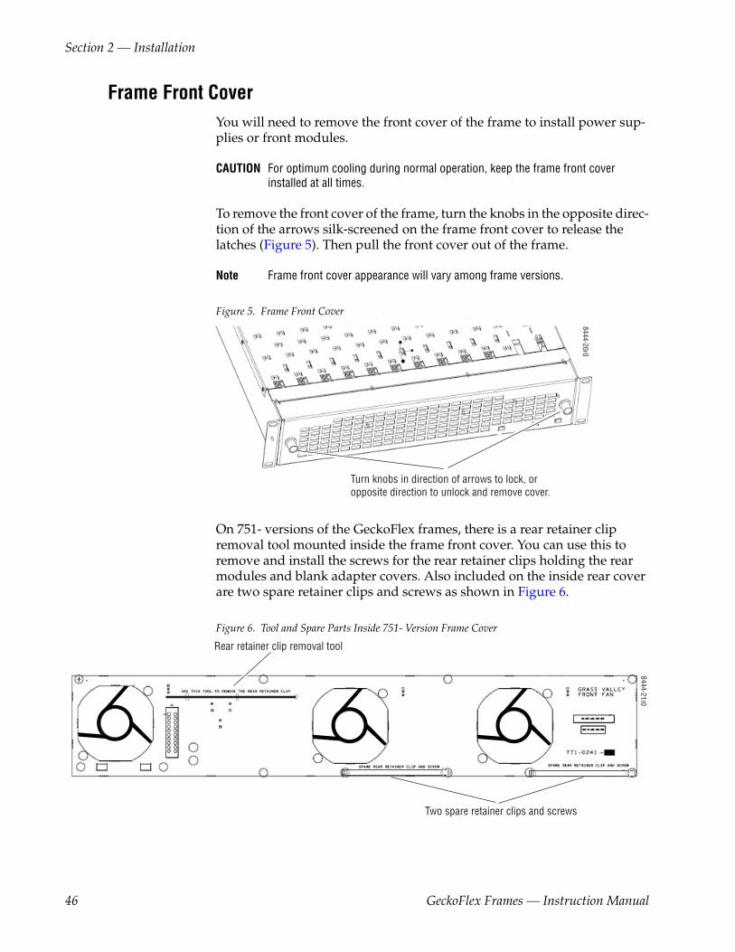
On 751- versions of the GeckoFlex frames, there is a rear retainer clip removal tool mounted inside the frame front cover. You can use this to remove and install the screws for the rear retainer clips holding the rear modules and blank adapter covers. Also included on the inside rear cover are two spare retainer clips and screws as shown in Figure 6.
Figure 6. Tool and Spare Parts Inside 751- Version Frame Cover
Turn knobs in direction of arrows to lock, or opposite direction to unlock and remove cover.
8444-20r0
Rear retainer clip removal tool
Two spare retainer clips and screws
8444-21r0
46 GeckoFlex Frames — Instruction Manual

Rack Mounting the Frame
Power Supply InstallationThe frame will come with a single GeckoFlex 125 Watt power supply installed in one of the slots on the far right. If you have ordered an optional redundant power supply, install it in the empty power supply slot as shown in Figure 7.
Note Refer to Power Supply Descriptions on page 48 if you do not have the power supplies described here.
Figure 7. Power Supply Installation
The power supply ejector tab is illustrated in Figure 8. It is used to extract and install the power supply. Make sure when installing the power supply, the locking pin is snapped into to the ejector to hold the power supply securely in place.
Figure 8. Power Supply Ejector Tab Locking Pin
8444
_25r
0
Power supply label
8444 -05
EjectorTab
Locking Pin
GeckoFlex Frames — Instruction Manual 47

Section 2 — Installation
Power Supply Descriptions
Older GeckoFlex frames were shipped with 100 Watt power supplies. The 100 Watt supply has a black ejector tab and a front shield with holes (shown on the left in Figure 9). Frames now ship with 125 Watt power supplies. The 125 Watt power supply has a white ejector tab and a metal grid over the front of the supply (shown on the right in Figure 9).
Note If you need to swap power supplies between GeckoFlex frames, always verify the wattage of the power supply by reading the power supply label (shown in Figure 7 on page 47). Mixing GeckoFlex 100 Watt and 125 Watt power sup-plies in the same GeckoFlex frame is possible but is not recommended.
Figure 9. 100 and 125 Watt GeckoFlex Power Supplies
Note Power supplies used in the 8900 Gecko frames (8900TF/TFN-A/-V) and the ones used in the GeckoFlex frames cannot be swapped. They are different lengths.
100 Watt Power Supply 125 Watt Power Supply84
44_2
6r0
48 GeckoFlex Frames — Instruction Manual

Module Installation
Module InstallationModule front, rear, and SFP fiber optic submodule installation is discussed here in general terms. Specific module installation, cabling, and genlock and fiber optic option submodule information is given in detail in the spe-cific module instruction manuals. All instruction manuals are available online at this URL in PDF format:
http://www.grassvalley.com/docs/modular
Every 8900 front media module installed in a GeckoFlex frame must have a corresponding rear module. Some GeckoFlex rear modules require two slots for the rear module. When 8900 modules are ordered, you will be advised as to which rear module to order. Some modules are rear modules only and have no corresponding front module. In this case, the front module slot cannot be used.
A module summary table is provided in Table 8 on page 38 for quick refer-ence. Always install the rear module first, followed by strap-mount sub-modules, then the corresponding front module. All modules are hot-swappable (can be installed or removed with power on).
CAUTION If there is no rear module, a blank rear adapter cover should be installed in all unused rear slots to meet ventilation and cooling requirements. Always leave the frame cover installed for normal operation. and proper cooling.
Some front modules have submodules that can be installed to provide Genlock timing for either the module it is installed on or to feed one of two Genlock timing buses from the modules installed in slot 1 and/or slot 3 of the frame. Modules may also have optional fiber optic submodules that require installation.
Note Detailed installation of the genlock submodule and strap-mount or cage-mount SFP fiber optic submodule options is covered in the specific front module instruction manual.
Module Installation Precautions
Please read and follow the precautions listed below before installing the front and rear modules and any submodules:
• Use standard anti-static procedures during installation. As modules can be installed or removed when the GeckoFlex frame is powered up, before removing the cover, please use an anti-static bracelet or heel straps tied to a metal part of the frame. See ESD Protection on page 27.
• Install the rear module first, then any genlock submodules (such as the 8900GEN-SM submodule), then any strap-mount fiber optic submod-ules, then the front module, then any fiber optic submodule cage-mount options.
GeckoFlex Frames — Instruction Manual 49

Section 2 — Installation
• When installing or removing a rear module, loosen or tighten the screws holding the rear retainer clips to the frame manually with the rear retainer clip tool provided inside the front cover of the frame (751- version frames). For 660- version frames without the tool, use a 2 mm (5/64”) hex screwdriver. Please do not use an electric screwdriver.
• Make every effort to leave the screws holding the retainer clips in place (do not remove them completely). They are very small and can easily drop into other equipment causing a shorting hazard. (Two turns of the screw should be enough to loosen the screws, 3 turns or more will remove it.)
• When installing a rear module, tighten the screws on the retainer clips just until snug. Do not apply more force than is necessary to seat the rear module. Refer to the torque specification in Table 14 on page 81.
• When using fiber optics, use anti-static precautions, and read the Fiber Optic Cleaning Requirement below before cabling.
Fiber Optic Cleaning Requirement
Before making any fiber optic cable mating connections and after every de-mating cycle, use an industry standard fiber optic cleaning kit, including oil-free compressed air, to clean the fiber connectors and the con-nectorized fiber end faces. This helps ensure optimum performance of the fiber optic interface. Industry standard fiber optic cleaning kits can be pur-chased on the web and in electronics stores.
Frame Monitor and 8900NET (Net Card) Network Interface ModulesThe GeckoFlex 8900FF frames support the use of the Frame Monitor module. The Frame Monitor module provides alarm reporting for the Frame Alarm only in an 8900FF frame. These modules are installed in the Controller slot of the frame (Figure 12 on page 55).
The GeckoFlex 8900FFN frame supports the use of the 8900NET (Net Card) Network Interface module that provides full functionality of the frame communication buses including:
• Frame Alarm,
• RS-232 Configuration, and
• 10Base-T Ethernet.
The 8900NET Network Interface module must be running software version 4.3.0 or later for full functionality as described in this manual. Updates for the manual are available free of charge from the Grass Valley ftp site.
For complete software update details, refer to the latest 8900NET (Net Card) Network Interface module Release Notes and Instruction Manual on the Grass Valley web site.
50 GeckoFlex Frames — Instruction Manual

Module Installation
Module Placement for Genlock Timing BusesBefore installing the front and rear module sets in the frame, it is important to understand an overview of the various ways that the 8900GEN-SM GeckoFlex Genlock submodule can be used and how genlock timing can be configured. This can influence module placement in the frame.
An 8900GEN-SM GeckoFlex Genlock submodule can be installed on a number of different GeckoFlex front modules in any 8900FFN frame (see Table 8 on page 38). The submodule can provide a local external genlock timing reference to the host module it is mounted on or it can be configured to transmit an external reference to the entire GeckoFlex frame on one of two frame buses.
When a GeckoFlex host module with an 8900GEN-SM submodule is installed in slot 1 of an 8900FFN frame, it can be jumpered on the module circuit board to transmit the external reference fed to the Genlock Loop BNCs on the rear module to Frame Bus 1. Frame Bus 1 is available to every slot in the GeckoFlex frame. Another GeckoFlex module in the frame can be configured to accept this reference using the web browser.
Frame Bus 2 can be transmitted from the GeckoFlex host module with an 8900GEN-SM submodule when the host module is installed in slot 3 of the frame. This bus is also fed to every slot in the GeckoFlex frame. The choice of which frame reference to use is made on the System Config web page for each individual module in the frame. This allows two different references to be fed simultaneously to the entire frame.
This functionality allows for a Primary and Secondary redundant configu-ration. This application allows a house reference input to be designated as the Primary timing source while a backup Secondary house reference can be configured to automatically take the place of the Primary if it fails. When the Primary timing source recovers, the user can set the system to return to the Primary source automatically or to reset the Primary manually and can also set the amount of time before the restored Primary is switched back.
The distribution of Frame Bus 1 from slot 1 and Frame Bus 2 from slot 3 cannot be changed, so plan the placement of your GeckoFlex modules to take advantage of the versatility of this functionality. This functionality is only available on modules that can accept the 8900GEN-SM submodule.
Refer to the 8900GEN-SM GeckoFlex Genlock Submodule Instruction Manual available online in PDF format for complete details on using this timing ref-erence. This timing information and using the Genlock submodule is included in each GeckoFlex module instruction manual that can use it.
GeckoFlex Frames — Instruction Manual 51

Section 2 — Installation
Rear Module InstallationThere are ten rear modules slots to accommodate either video or audio modules (module types can be mixed in a frame). Where no modules will be installed in a slot, leave the blank rear adapter covers in place. The frame ships from the factory with ten blank rear adapter covers installed.
There are a number of different types of rear modules for the various GeckoFlex front module applications. All rear modules (and blank rear adapter covers) are installed in the same manner. These instructions are provided for a general overview of module installation.
Note Refer to the specific module instruction manual when installing the front, rear, modules and any optional submodules for more detailed information.
To install a rear module, follow these steps and refer to Figure 10 on page 53 for 660- version frames and Figure 11 on page 53 for the 751- version frames:
1. Determine the location of the rear module to be installed.
Note If the rear module requires two slots it cannot be installed in slot 10.
2. To remove a blank rear adapter cover (or a rear module already present), loosen the two screws holding each retainer clip on the blank rear adapter cover or rear module to the frame with the rear retainer clip tool provided inside the front cover of the frame (751- version frames only, Figure 6 on page 46) or a 2 mm (5/64”) hex screwdriver.
CAUTION Do not remove the retainer screws completely. They are very small and can easily drop into other equipment causing a shorting hazard.
3. Remove the two retainer clips and then the blank rear adapter cover using a needlenose pliers, or, in the case of the 751- frame, one of the retainer clips.
4. Insert the corresponding rear module in the slot.
5. Replace both rear retainer clips on each side of the rear module and tighten the screws about two turns until snug (just enough to secure the rear module). The torque specification for attaching the screws is 4-5 inch-lb/0.45-0.6Nm.
CAUTION Do not overtighten the screws; the retainer clips should not bend or bow.
Blank Rear Adapter Covers
When all desired modules have been installed, make sure a blank rear adapter cover is installed in every empty rear slot to ensure proper cooling of the frame.
52 GeckoFlex Frames — Instruction Manual

Module Installation
Figure 10. GeckoFlex Frame Rear – 660- Version
Figure 11. GeckoFlex Frame Rear – 751- Version
8521_02
Use needlenose pliersto pull out blank afterremoving retainer clips.
8444
23r0
Use retainer clip or
to pull out blank afterremoving retainer clips.
needlenose pliers
GeckoFlex Frames — Instruction Manual 53

Section 2 — Installation
Submodule InstallationThere are several types of submodules that can be installed on various 8900 front modules. Some require installation on the front module before it is installed in the frame. Each submodule type has its own instruction manual and is also covered in detail in the specific module instruction manuals which use it. Refer to Table 8 on page 38 for a list of front modules and the submodule types used. A summary of each one is given below.
Genlock Submodules
There are two different genlock submodules used on 8900 modules, the 8900GEN-SM and the 8900FSS Genlock submodules. These need to be installed on the front module before it is installed in the frame. Refer to the specific front module and/or submodule instruction manual for detailed installation instructions.
SFP Fiber Optic Submodules
There are two different types of SFP Fiber Optic submodule options, the SFP Fiber Optic cage-mount and the SFP Fiber Optic strap-mount. The front GeckoFlex module determines which type to use. Refer to the sum-maries given below.
CAUTION The Fiber Optic submodules are static sensitive. Use static handling precau-tions when installing or removing the submodule and follow fiber optic cleaning requirements (Fiber Optic Cleaning Requirement on page 50).
Strap-mount SFP Fiber Optic Submodules
Install the strap-mount SFP modules on the front module before installing it into the frame. For instructions on installing the strap mount SFP fiber optic submodules, refer to the specific module instruction manual or the instruction sheet that comes with the submodule. Refer to the example in Figure 31 on page 86.
Cage-mount SFP Fiber Optic Submodules
After the front and rear modules have been installed, the SFP Fiber Optic cage-mount submodule option must be installed into the rear module metal cage labeled Fiber. The SFP submodule is hot-pluggable and may be installed or removed with power applied to the module. Refer to the spe-cific module and/or submodule instruction manual for installation and cabling instructions. Refer to the example in Figure 30 on page 85.
Determining Which SFP Submodule to Use
To determine the correct SFP submodule to use for your front module type and application, refer to Fiber Optic Submodules on page 85.
54 GeckoFlex Frames — Instruction Manual

Module Installation
Front Module InstallationThere are ten front cell locations in each frame to accommodate either video or audio modules (module types can be mixed in a frame). These are the ten cells located on the left side of the frame. Refer to Figure 12. After installing the rear module and any required submodules on the front module (Sub-module Installation on page 54), install the front module in the front slot cor-responding to the corresponding installed rear module.
The two cells on the right of the frame are allocated for the power supplies only (refer to Power Supply Installation on page 47).
The third cell from the right is the Controller slot, allocated only for the Frame Monitor (8900FF frame) or 8900NET (Net Card) Network Interface module (8900FFN frame). These modules provide the interface for the forced-air cover, as well as the Frame Alarm reporting. For additional infor-mation concerning the Frame Monitor and 8900NET Network Interface modules, refer to Section 4-Monitoring and Control.
Note As the module can be changed when the GeckoFlex is powered on, before removing the cover, always use an anti-static bracelet tied to a metal part of the frame.
Figure 12. GeckoFlex Frame Front
8444
_14
Slide top and bottom card carriers on module over top and bottom guides on right of slot.
Module installed
8900NET or Frame Monitor inController slot
Locking Pin
Card Carriers
Card Carriers
Front Module Side View
GeckoFlex Frames — Instruction Manual 55

Section 2 — Installation
Frame ConnectionsOnce you have rack-mounted the frame, you will need to connect the AC power cords and connect the serial port and/or the Ethernet port depending on the needs of your installation.
CAUTION Please do not connect power until instructed to do so. There is no power switch on the frame. Connecting the AC power cords to a power source will power up the frame.
The power/communication AC Rear section of the frame (Figure 13 on page 57 for 660- frame versions and Figure 14 on page 57 for 751- frame versions) provides the following connections:
• AC Power Connections – J1 (standard) and J2 (optional redundant). Connection and power up is covered in Section 3-Power Up.
• Serial Port J102 – DB9 connector labelled RS-232. Requires the 8900NET (Net Card) Network Interface module or the Frame Monitor module for using the Frame Alarm connections (pins 8 and 9 of RS-232 connector), and
• ETHERNET Connection J103 – Ethernet RJ-45 connector (requires the 8900NET (Net Card) Network Interface module) for providing a 10Base-T Ethernet network connection. Connection and configuration is covered in Section 4-Monitoring and Control.
• Earth Grounding – a ground lug is provided for grounding the 751- frame the equipment rack if desired.
56 GeckoFlex Frames — Instruction Manual

Frame Connections
Figure 13. Power and Communication AC Rear – 660- Frame Version
Figure 14. Power and Communications AC Rear – 751- Frame Version
8444_24r0
Ground lug
GeckoFlex Frames — Instruction Manual 57

Section 2 — Installation
Frame Alarm ConnectorUse of the Frame Alarm requires the presence of either the Frame Monitor or 8900NET (Net Card) Network Interface module in the 8900FF or 8900FFN frame. Frame Monitor module features are discussed in Section 4-Monitoring and Control in this manual. For information on the 8900NET (Net Card) Network Interface module see the 8900 Network Inter-face Module Instruction Manual.
The Frame Alarm is accessed through pins 8 and 9 of the RS-232 DB-9 con-nector (J102) as shown in Figure 13 on page 57. The pinout for the RS-232 DB-9F connector is given in Table 9. Refer to Frame Alarm Example on page 59 for using the port in an alarm circuit.
Frame Alarm Conditions
The conditions monitored by Frame Alarm reporting are:
• Frame Health
• Power Supply 1 voltage
• Power Supply 2 voltage
• Fan rotation
• Frame temperature
• Module Health Bus Information (except older audio modules)
• Power supply voltage
• Signal present at input
• EQ warning
The Module Health bus provides a means for older or less capable modules (such as DAs with no microprocessor) that cannot communicate over the Frame serial bus to report alarm conditions to the Frame Monitor or 8900NET module. The reporting is done using a voltage level sent by the
Table 9. RS-232 Connector Pinouts
FrameRS-232 Port Pin Function
1 N/C
2 TX
3 RX
4 N/C
5 Gnd
6 N/C
7 N/C
8 Frame Alarm
9 Frame AlarmRS232
1
95
6
8444
_10
58 GeckoFlex Frames — Instruction Manual

Frame Connections
module to the Frame Alarm connector. When a problem occurs on the module, the Module Health bus will indicate that a problem exists on the module but will not indicate what the problem is.
Alarm conditions are enabled or disabled by using the Alarm Reporting DIP switch(es) on either the Frame Monitor or 8900NET modules and, when an 8900NET module is present, the Frame Alarm and LED Reporting web pages. Refer to Enabling Alarms and Fan Speed Control Option on page 71 for the Frame Monitor module. For information on setting the 8900NET switches and using the Frame Alarm and LED Reporting web pages, refer to the 8900 Network Interface Module Instruction Manual.
In addition to fault reporting through the Frame Alarm connector, there is a red Fault LED on the 8900FF/FFN front cover. This LED is off when no fault conditions are detected and on or pulsing when either an internal fault or a signal error is detected.
Frame Alarm Example
Refer to Figure 15 for an example of a typical alarm schematic using pins 8 and 9 of the RS-232 port.
Figure 15. Typical Alarm Schematic for Frame Alarm
The impedance between the pins 8 and 9 of the RS-232 connector can be in one of two states:
• Open – less than 100 μA of current will flow with 5 volts across the pins, and
• Closed – less than 0.2 V will appear from pin 8 to pin 9 with 20 mA of current flowing.
There are three operational conditions (capability is module dependent, refer to specific module instruction manual):
• Open – no faults,
• Closed – there is an internal fault, and
• Pulsing – there is a missing or invalid signal on one or more of the modules.
Alarm LED
470 ohms
4.7k Ohms
+5V
RS232 Pin 8
RS232 Pin 9
4.7k Ohms
330Ohms
2N4126 (or equivalent)
8444-11
GeckoFlex Frames — Instruction Manual 59

Section 2 — Installation
Module CablingThis section describes a general overview of module cabling. All module connections are made on the rear modules. Each front and rear module set has specific cabling requirements covered in the instruction manual for each module.
Loop-through Input Connectors
Some rear modules, including the 8900V-R rear for Gecko video modules, have loop-through connectors for looping signals to other destinations.
Note No more than five digital modules should be looped. Use cables less than two meters in length, and an input cable of less than 200 meters of Belden 8281 or 1694A.
If not used for looping, the unused loop-through connector must be exter-nally terminated. The recommended termination for serial digital signals is CONARE BCP-TA (or equivalent).
Performance of looping inputs to equipment other than 8900 modules has not been verified; monitor signal quality carefully when configuring such a system.
Serial digital SD SDI video is a wideband RF signal. Be sure to protect the data from environmental noise. The serial digital SD SDI signal is attenu-ated by as much as 30dB after traveling through 1000 feet of Belden 1694A cable. An equalizer must be used to restore the signal so data can be recov-ered. The equalizer boosts the serial digital video signal and any environ-mental noise on the line. Data corruption takes place if the environmental noise is large enough to cause pick-off errors in the equalizer.
When connecting serial digital HD or SD SDI video signals to and from the 8900 Series frame:
• Check the specific front module instruction manual for the recom-mended cable length specifications for HD SDI and SD SDI signals.
• Use high quality BNC connectors to ensure continuous shield connec-tions.
• Use high quality cable (Belden 1694A).
• Use one continuous cable for long cable runs. Avoid using patch panels or BNC barrel connectors.
Note These recommendations become even more important in noisy environ-ments (subject to radio frequencies and static discharges) with long cable runs.
60 GeckoFlex Frames — Instruction Manual

Frame Connections
Video and Audio Input/Output Connections
All 8900 modules from Gecko frames can be installed in any GeckoFlex frame with one of two generic rear modules, the 8900V-R (Table 10) for video module applications and the 8900A-R (Table 11) for audio applica-tions. Cabling of these modules is described in each specific module instruction manual.
8444_15
8900A-R
Pin 3Pin 2Pin 1
Pin 1Pin 2Pin 3
Table 10. 8900V-R Rear Module and Corresponding Front Modules
8900V-R Rear Module Used With 8900 Model #
8901 DA 8941
8902 DA 8950DAC
8906 DA 8950ADC
8911 8960DEC
8914 8960ENC
8916 8964DEC
8920ADC 8964ENC
8920ADT 8964FS
8920DAC 8964MON
8920DMX 8981FS
8920MUX 8981NR
8931 8990ARC
8937/-D
Table 11. 8900A-R Rear Module and Corresponding Front Modules
8900A-R Rear Module Used With 8900 Model #
8910ADA-M/ST
8910ADA-SR
8912RDA/-D
8921ADT
8921DAC
8900V-RJ1 J2
J3 J4
J5 J6
J7 J8
J9 J10
GeckoFlex Frames — Instruction Manual 61

Section 2 — Installation
62 GeckoFlex Frames — Instruction Manual

Section 3Power Up
IntroductionThis section contains information about:
• Power Connections
• Applying Power
CAUTION Verify that the power supplies are fully seated in their slots. Ejector tabs should click into place when snapped on the locking pin on the module (see Figure 7 on page 47). Read this entire section before applying power to the frame.
Power ConnectionsOne power cord is included in the frame box when shipped. Verify that you have the proper power cord for your mains line standard.
If the power cord was not shipped or is not appropriate, you are advised to use a power cord with the following specifications:
• Device end of cable: CEI 320 compliant connector;
• Flexible wire: 3x1 mm2 cross section or 18 AWG, 10A minimum, 250 Volts compliant with the applicable standard or rules of the country where the device is installed;
• Mains outlet end of cable: plug compliant with the applicable standard or rules of the country where the device is installed.
Each power supply has an operating range of 100 to 240 Volts. Please use the appropriate power cord for the voltage and standard of the country where the device is being installed. Line voltage is auto-sensing with this power supply so selection of line voltage is not required.
GeckoFlex Frames — Instruction Manual 63

Section 3 — Power Up
For each power supply installed, AC power is fed through a line cord to a socket (J1 and J2) on the rear of the frame (see Figure 16 for the 660- frame version and Figure 17 for a 751- frame version). For the standard power supply 1, connect the AC cord to J2. If you have installed a second, redun-dant supply, connect the other power cord to J1.
Note To maintain maximum redundant power, ensure that each power supply cord is plugged into a separate branch circuit.
Figure 16. Power and Communication AC Rear – 660- Frame Version
Figure 17. Power and Communication AC Rear 751- Frame Version
8444_24r0
64 GeckoFlex Frames — Instruction Manual

Power Connections
The connection panel should comply with the legislation in force in the country of installation. The connection panel must be positioned in the rack in such way that the plug and power cord are within easy reach for switching off purposes.
Canadian Certified Power CordsCanadian approval includes the products and power cords appropriate for use in the North America power network. All other power cords supplied are approved for the country of use.
Canadian Certified AC AdapterCanadian approval includes the AC adapters appropriate for use in the North America power network. All other AC adapters supplied are approved for the country of use.
Line Cord RetainerTo help prevent accidental loss of power, the AC line cords should be held in place by the power cord retention clips on the AC connectors (Figure 18).
Figure 18. Power Cord Retention Clip
To properly install the line cord, follow these steps:
1. Ensure that the retention clip is inserted properly into the holes of the screw caps.
2. Rotate the retention clip sideways, and plug the power cord into the receptacle.
3. Rotate the retention clip back onto the plug body to hold the power cord in place.
Retention Clip
8444 -12
GeckoFlex Frames — Instruction Manual 65

Section 3 — Power Up
Applying PowerConnect the power cords to separate AC mains sources. Verify that the green Power LEDs for each power supply (assuming a redundant supply is present) PS1 and PS2 are illuminated (Figure 19).
If the frame is an 8900FF or 8900FFN model (with fans), check the red FAULT LED. It should be off if the device is operating correctly and no module faults are reported to the 8900NET (Net Card) module.
Figure 19. Power Indicator LEDs (FF frame shown)
Other specific indicator LEDs can be viewed on the Frame Monitor or 8900NET module with the front cover removed. Frame Monitor module indicators are discussed in Section 4-Monitoring and Control on page 69. If you have a 8900NET module installed in the frame, see the 8900NET Network Interface Module Instruction Manual for indicator details.
Verify Power Supply Demand
Usethislink
For 8900FFN frame operation (with 8900NET (Net Card) module, you can verify that your total frame power supply demand is correct for the power supply installed by linking to the Power Supply/Demand web page from the Frame links (see link at left). The Power Supply/Demand web page is shown in Figure 20 on page 67.
Total power demand for the installed modules, Net Card and fans in the front cover is shown at the bottom of the web page. An Installed Power Supply setting is provided to identify to the frame what wattage power supplies are installed in the frame. The GeckoFlex frame (751-) currently ships with 125 Watt power supplies and the Installed Power Supply setting is set for 125 Watt at the factory.
CAUTION The Total Demand should never exceed the Total Supply. If this occurs, an alarm will be generated.
Fault condition indicator LED Power indicator LEDs
8444-13r1
66 GeckoFlex Frames — Instruction Manual

Applying Power
The Installed Power Supply wattage setting on the Power Supply/Demand web page is not auto-sensed by the frame. It must be set manually by the user. Earlier version GeckoFlex frames were shipped with 100 Watt power supplies, so if you have or install 100 Watt supplies in a frame, you will need to select the proper power supply wattage for the Installed Power Supply setting.
Note Combining 100 Watt and a 125 Watt power supplies in the same GeckoFlex frame is possible but not recommended. Refer to Module Installation on page 49 for complete descriptions of the power supplies.
Figure 20. Power Supply/Demand Web Page
GeckoFlex Frames — Instruction Manual 67

Section 3 — Power Up
68 GeckoFlex Frames — Instruction Manual

Section 4Monitoring and Control
IntroductionThe GeckoFlex 8900FF/8900FFN frames offer monitoring and remote control capability by providing two types of frame communication modules that can reside in the Controller slot of the frame (see Figure 12 on page 55):
• Frame Monitor module (8900FF Frame), or
• 8900NET (Net Card) Network Interface module (8900FFN Frame).
The 8900NET (Net Card) Network Interface module supports all the func-tionality of the Frame Monitor module plus the 10 Base-T Ethernet bus for web-based GUI control and monitoring. An abbreviated overview of con-figuring the 8900NET module to interface to an Ethernet network is included in this section. For detailed information on configuring and using the 8900NET Network Interface module, refer to the 8900NET Network Interface Module Instruction Manual available on-line in PDF format at this URL:
www.grassvalley.com/docs/modular
The Frame Monitor module is described in this manual (see Frame Monitor Module on page 70). The Frame Monitor module is an interface for the 8900FF forced-air cover and Frame Alarm fault reporting. It is used where Ethernet connection is not required.
The Frame Monitor module provides:
• Variable power to the fan front cover to regulate fan speed
• Module presence indication
• LED display for quick diagnostics of alarm conditions
• DIP switch for enabling and disabling alarms and the variable fan speed (set to Maximum by default for higher powered conversion and HD SDI modules).
GeckoFlex Frames — Instruction Manual 69

Section 4 — Monitoring and Control
Frame Monitor ModuleThe Frame Monitor module comes installed in the 8900FF frame. It pro-vides indicator LEDs on the front of the module (visible when fan front cover is removed) that report alarm conditions and module power status.
When on, the LEDs indicate:
• TEMP — Over-temperature problem
• PS2 — Power supply position 2 health problem
• PS1 — Power supply position 1 health problem
• FAN — Cooling fan is not rotating
• MOD — Module health bus error
• INHIB — Disabled module health bus
• FAULT — Reports that one or more of the above alarm conditions is present and the other Fault LEDs on the module should be checked. This LED is visible through the fan front cover Fault window.
The front edge of the Frame Monitor module is shown in Figure 21.
Figure 21. Frame Monitor Module Front View
Fan (red)
Module Health (red)
PS1 (red)PS2 (red)
Temperature (red)
S1
87
65
43
21
Power (green)
Fault detected (red)
Module Health Inhibited (yellow)
Configuration DIP switch S1
0636 -16
Red = FaultGreen = OKYellow = Mode Active
LED Color Key
70 GeckoFlex Frames — Instruction Manual

Frame Monitor Module
Enabling Alarms and Fan Speed Control OptionThe Frame Monitor module has an eight position DIP switch (S1) that enables or disables the alarm functions and the variable fan speed function.
Refer to Figure 21 on page 70 for the location of S1 and Table 12 for the pos-sible settings. A settings table is also silk-screened on the module.
Frame Monitor Module Indicator LEDsThe possible LED status and conditions indicated are shown in Table 13.
Table 12. Configuration DIP Switch Settings
Segment Left Position (open) Right Position (closed)
1 PS1 Fault Reporting Enabled PS1 Fault Reporting Disabled
2 PS2 Fault Reporting Enabled PS2 Fault Reporting Disabled
3 Overtemp Fault Reporting Enabled Overtemp Fault Reporting Disabled
4 Fan Fault Reporting Enabled Fan Fault Reporting Disabled
5 Module Fault Reporting Enabled Module Fault Reporting Disabled
6 Fan Speed Controlled by Temperature Fan Speed Fixed at Maximuma
a Fan speed on the GeckoFlex frames is set for Maximum by default to assure cooling for higher powered conver-sion and HD modules. Fan speed can be reset to be controlled by temperature if desired for lower power modules.
7 Not Used
8 Not Used
Table 13. Indicator LEDs and Conditions Indicated
LED LED State Condition
Power(green)
Off Power is off or onboard regulator has failed
On continuously Module is powered
PS2 (red)
Off Normal operation or alarm disabled
On continuously Power supply 2 is present and reporting an alarm condition
PS1 (red)
Off Normal operation or alarm disabled
On continuously Power supply 1 is present and reporting an alarm condition
FAN(red)
Off Normal operation or alarm disabled
On continuously One or more fans in the front cover assembly is not rotating
MOD(red)
Off Normal operation or alarm disabled
On continuously Module health bus is not disabled and one or more modules is reporting an internal fault
Flashing One or more modules is reporting a data error
INHIB(yellow)
Off Normal operation or alarm disabled
On continuously A non-compliant module in the frame has disabled the module health bus
FAULT (red)
Off Normal operation
On continuously One or more of the onboard fault LEDs is illuminated or flashing
GeckoFlex Frames — Instruction Manual 71

Section 4 — Monitoring and Control
Establishing 8900FFN Frame Network Identity8900FFN Frame network connection is done by configuring the 8900NET Network Interface module installed in the frame, using either the RS-232 port (refer to Frame RS-232 Serial Port below) or the Grass Valley PC appli-cation NetConfig (ref to NetConfig Application on page 77) to establishes the frame’s network identity to enable the operation of the Web-based GUI. The abbreviated information given here is given in more detail in the 8900NET Network Interface Module Instruction Manual available online.
8900NET Network Interface modules are shipped from the factory with the following network parameters configured on the module:
• IP Address: 192.168.0.105
• Gateway Address: 192.168.0.1
• Subnet Mask: 255.255.255.0
Frame RS-232 Serial PortWhen using the serial port on the rear of the frame, a PC running a terminal emulation application is used to set the initial parameters for network com-munication. Once initial identity is established, the GUI can be used to make subsequent changes to the networking parameters. Parameters estab-lished include:
• Local IP Address,
• Gateway IP Address,
• Subnet Mask, and
• Default Route.
Note If the GeckoFlex frame is to be connected point-to-point to a single PC work-station, both the frame and the PC must be on the same Subnet.
RS-232 Communication Port Cable
The nine-pin RS-232 connector is used to connect the frame to a PC to ini-tially set the frame’s network communication parameters. After network communication is established, subsequent changes to these parameters can be made using the network GUI.
CAUTION The RS-232 cable should be removed after completing the initial frame setup. Leaving a long serial cable connected to the frame without a connection at the other end may freeze the 8900NET module startup routine.
Note The cable used for this connection is a DB-9F to DB-9M, straight-through cable available from Grass Valley as part of cable kit model 8900CAB (10 ft./3 m length).
72 GeckoFlex Frames — Instruction Manual

Establishing 8900FFN Frame Network Identity
The male end of the cable connects to the RS-232 connector on the GeckoFlex frame (see Figure 22) and the female end connects to either Com1 or Com2 on the PC, depending upon the configuration of the com-puter’s I/O ports.
Figure 22. RS-232 to Initialization PC Cable and Pinout
If the PC uses a 25-pin RS-232 connector, use a cable adapter as shown in Figure 23.
Note The 25-pin adaptor is available from Grass Valley as part of cable kit model 8900CAB.
Figure 23. DB-9 Cable and DB-25 Cable Adaptor Pinout
RJ-45connector
RJ-45connector
Pin Pin PinPin12345678
12345678
36154287
12345678
To PC network cardRJ-45 connector
Pin 1
PC with network card and net browser software
Category 5, UTP Crossover Cable
8444_17
Ethernet
8900FFN Frame
123456789
123456789
832
207645
22
0612 -11
25-pin 25-pin9-pin 9-pin9-pin12 Tx3 Rx4567892022
1Tx 2
Rx 3456789
9-pin
DB-25Female
DB-9Male
DB-9Female
DB-9Male
Pinout
Pin 5
Pin 1
Pin 9
DB-25FemalePinout
Pin 1
Pin 13
Pin 14
GeckoFlex Frames — Instruction Manual 73

Section 4 — Monitoring and Control
Ethernet Cable
The 8900NET module enables the frame’s RJ-45 Ethernet connector. Through this port the GeckoFlex frame can connect to:
• A single PC with a network card (point-to-point), or
• A local area network (LAN) through a network hub.
Point-to-Point Connection
Figure 24 illustrates the crossover cable connection and pinout for a point-to-point connection to the controlling PC.
Note This Category 5, UTP Crossover Cable is available from Grass Valley as part of cable kit model 8900CAB (10 ft./3 m length).
Figure 24. Point-to-Point RJ-45 Connection and Cable Pinout
RJ-45connector
RJ-45connector
Pin Pin PinPin12345678
12345678
36154287
12345678
To PC network cardRJ-45 connector
Pin 1
PC with network card and net browser software
Category 5, UTP Crossover Cable
8444_17
Ethernet
8900FFN Frame
74 GeckoFlex Frames — Instruction Manual

Establishing 8900FFN Frame Network Identity
Local Area Network (LAN) Connection
Figure 25 illustrates the cable connection for a LAN connection to a network hub.
Note Because of varying length requirements and ready availability from network equipment suppliers, this cable is not supplied by Grass Valley.
Figure 25. LAN RJ-45 Connection and Cable
Setting Frame Network IdentityAfter you have connected the PC to the RS-232 port and established com-munication using the terminal emulation application, press the Enter/Return key several times to see the active prompt ->.
At the prompt enter:
setup
You will see:
-> setup
Here are the current parameters and their values:
Local IP Address: 192.168.0.105Gateway IP Address: 192.168.0.1Subnet Mask: 255.255.255.0If a change is made, it is necessary to reboot
RJ-45connector
RJ-45connector
Pin Pin PinPin12345678
12345678
12345678
12345678
To network hubRJ-45 connector
Ethernet
Pin 1
Network Ethernet Hub (typical)
8444_18
Category 5, UTP Cable
8 7 10 BaseT6 5 4 3 2 1hp
8900FFN Frame
GeckoFlex Frames — Instruction Manual 75

Section 4 — Monitoring and Control
this machine. This will occur automatically whenyou have completed making changes.
Do you wish to change any of the values? y/n (n): y
For each parameter, you will be given the name of the parameter and its current value in parenthesis. To change it, just type in the new value. If you don't wish to change it, just hit the Enter key.
If you make a mistake on a previous value, continue with the remaining parameters; you will be given an opportunity to modify the value again.
Please ensure that you change from Factory defaults to your network parameters.
The local Ip Address is the Internet address of this machine. It consists of four numbers separated by pe-riods ('.'). Each number can be in the range of 0 to 255. For example: 192.167.221.45There must an IP address.
IP Address (192.168.0.105):
The Default Route is the Internet address of the ma-chine which routes network packets outside of the lo-cal network. It consists of four numbers separated by periods ('.').
Each number can be in the range of 0 to 255.For example: 192.167.221.1If you respond with a single period (.),a default route will not be assigned.
Default Route (192.168.0.1):
The Subnet Mask is used in the routing algorithm.The Net Card will use the mask to determine if a ad-dress is in local net or to send the message to the default. It consists of four numbers separated by pe-riods ('.').
Each number can be in the range of 0 to 255.For example: 192.167.221.1
If you respond with a single period (.),a Subnet Mask will not be assigned.Subnet Mask (255.255.255.0):
76 GeckoFlex Frames — Instruction Manual

Establishing 8900FFN Frame Network Identity
NetConfig ApplicationWith 8900NET Network Interface modules running version 4.2.0 or later in an 8900FFN GeckoFlex frame, network parameters can also be set using the Grass Valley PC application NetConfig (Network Configuration Applica-tion). NetConfig is a very useful PC software tool for configuring, moni-toring, and setting up NetConfig-enabled Grass Valley devices. This application is required for software updating on most GeckoFlex modules.
The most recent release of the NetConfig application is available free of charge from the Thomson Grass Valley ftp site at this URL:
ftp://ftp.thomsongrassvalley.com/router/NetConfig
This section provides an overview of using NetConfig for setting network parameters. Refer to the NetConfig Instruction Manual available online for information on using this tool. If you have purchased the Newton Control Panel system, NetConfig is also included in the installation process with the option.
Connecting 8900FFN Frame to NetConfig LAN
Connect the Ethernet port on the rear of the 8900FFN frame to a router or hub (Figure 25 on page 75) on the same LAN as your PC running Net-Config.
Open the NetConfig application and on the left of the NetConfig window, open the IP View directory. Find your frame on the menu tree in the IP View. It will be named Frame with the factory default IP Address (Figure 26).
Figure 26. New Frame in NetConfig IP View
CAUTION If you have installed more than one frame on the LAN, you will see a number of frames with the same IP Address. This will cause NetConfig to report an error IP Error. It is recommended to connect one frame at a time.
GeckoFlex Frames — Instruction Manual 77

Section 4 — Monitoring and Control
To change the IP Address, do the following:
1. Select the Set IP button at the top of the NetConfig window to open the Change IP Addresses window (Figure 27).
2. Select the 8900 Frame choice in the pulldown to view only the 8900 frames on this LAN.
3. Click on the frame you wish to change and select the Edit button at the bottom right of the window.
Figure 27. Change IP Address Screen
This will bring up the Change IP Addresses Configuration fields shown in Figure 28.
Figure 28. Change IP Addresses Pop-Up
78 GeckoFlex Frames — Instruction Manual

Establishing 8900FFN Frame Network Identity
4. Enter the IP Address, Subnet Mask and Gateway for your facility and select the OK button. If you attempt to assign an IP Address that is already assigned to another device a warning message will be displayed.
5. If this is a valid IP address, a confirmation screen will come up with the frame highlighted in yellow (Figure 29). Select Apply Changes to apply these values.
6. Select Status Refresh to update the list.
Figure 29. Change IP Confirmation Window
This frame should now be networked into the LAN and the frame modules can be controlled through NetConfig.
For complete details on using NetConfig, locate the NetConfig Instruc-tion Manual online under the Newton Control Panel category.
GeckoFlex Frames — Instruction Manual 79

Section 4 — Monitoring and Control
80 GeckoFlex Frames — Instruction Manual

Section 5Specifications
IntroductionThis section discusses specifications for the GeckoFlex frames and the 8900F-PSX 100W and 8900U-PSX 125W power supplies. Refer to the spe-cific module instruction manual for the specifications for a particular front module.
Note All specifications are subject to change without prior notice.
Frame SpecificationsSee Table 14 for a list of the GeckoFlex frame specifications.
Table 14. GeckoFlex Frame Specifications
Parameter Value
8900V-R Rear Modules
Input Type 75 Ω loop through BNCs (shield-isolated from ground)
Termination (Serial Digital) CONARE BCP-TA (or equivalent, customer-supplied)
Input/Output Type Eight 75 Ω BNCs
Rear retainer clip screw torque 4-5 inch-lb/0.45-0.6Nm
8900A-R Rear Modules
Input Type 75 Ω loop through BNCs (shield-isolated from ground)
Termination (Serial Digital) CONARE BCP-TA (or equivalent, customer-supplied)
Input/Output Type Two 75 Ω BNCs
Ten 3 pins connectors
Rear retainer clip screw torque 4-5 inch-lb/0.45-0.6Nm
Frame Fault Reporting
Connector Type DB-9F pins 8 and 9 of RS-232 connector
Maximum Current — Alarm OFF 100 µA when voltage < 24 V is applied
Maximum Voltage — Alarm ON 2 V with current < 20 mA
Maximum allowable voltage — center conductor to shield 24 V
GeckoFlex Frames — Instruction Manual 81

Section 5 — Specifications
Maximum allowable current 20 mA
Front Panel Indicators
PS 1 & PS 2 Green LED — ON indicates operating correctly
Fault (FF/FFN front covers only) Red LED — ON indicates an error or failure
Operating Conditions
Input voltage range 100 V to 240 VAC, 50 Hz-60 Hz
Maximum input current- total of the both power supplies- with only one power supply in operating
1.5 A1.2 A
Power Inputs Two independent AC inputs
Connector Type type A device connected by a non-industrial CEI 60320 compliant plug
Maximum power dissipation 8900FX frame: 30 W8900FF and 8900FFN frames: 125 W
Earth Grounding TN/TTFor Norway only, this device can be connected to an earthing arrangement of IT type for a voltage between phases of 230V.
Isolation class I
installation category II
Inrush current 20 A @ 230 V (cold start)
Overcurrent protection Integrated protection, cannot be accessed or reset
Mechanical
Height 2 RU, 3.46 inches (88 mm)
Width 17.60 inches (447 mm)
Depth 14.58 inches (370.3 mm)
Weight with no modules, 1 power supply 8900FX frame: 18.55 lb. (8.4 kg) 8900FF and FFN frames: 19.4 labs (8.8 kg)
Redundant power supply 1.1 labs (0.5 kg)
MTBF at 40°C in hoursBackplaneRear ACFront Fan8900V-R8900A-R
8,756,6005,319,2002,781,70032,894,80030,303,100
Table 14. GeckoFlex Frame Specifications - (continued)
Parameter Value
82 GeckoFlex Frames — Instruction Manual

Power Supply
Power SupplySee Table 15 for a list of power supply specifications.
Table 15. Power Supply Specifications 100/240V
Parameter Value
Inputs
Voltage Range 100-240 V, continuous range
Frequency 47Hz to 63Hz
Outputs
Voltage/Current +12.4 V @ 8 A and –12.4 V @ 1.5 A, common ground (total not to exceed 125 W)
Load/Line Regulation ± 3% for loads from 100 mA to 5 A + 7%, – 3% for loads from 0 to 100 mA
Current Limit +12 V < 10 A under short circuit conditions –12 V < 7 A under short circuit conditions
Status Range (healthy) +12 V + 8% – 4%; –12 V + 8% – 4%
Test Points Three: +12 V, –12 V, and ground
Power Factor Correction Complies with EN61000-3-2 Class D
Efficiency 80-90%
Overheating Integrated
Overload Integrated (the power supply fuse cannot be accessed and reset)
MTBF at 40°C in hours 300,000
GeckoFlex Frames — Instruction Manual 83

Section 5 — Specifications
84 GeckoFlex Frames — Instruction Manual

Fiber Optic Submodules
IntroductionThere are a number of different SFP fiber optic submodules available for fiber ready modules in the Grass Valley Modular product line. The front module type and software version determine what submodule can be used. The submodules that can be used on fiber-ready front modules are cross-referenced in the following tables:
• Submodule to Module Compatibility: this table cross-references sub-modules to the modules they can be used on. (Table 16 on page 87)
• Legacy Submodule Compatibility: This table cross-references legacy submodules that can be used with current modules. (Table 17 on page 88)
The tables use the following legend characters to identify the different types of submodules:
• C = Cage-mount: On a front module with a metal cage as shown in Figure 30, the submodule is inserted into the cage at the rear of the frame after the front module is installed. Use of a submodule type will depend on the capability of the front module.
Figure 30. Cage Mount Front Module
Cage Mount
GeckoFlex Frames — Instruction Manual 85

Fiber Optic Submodules
• S = Strap-mount: A strap-mount front module, as shown in Figure 31, requires a kit that includes an SFP fiber optic submodule, a mounting bracket, and a cable assembly. The submodule is installed on the front or the rear of the module circuit board (depending on the module type) with the mounting bracket. The cable assembly is installed from the submodule output connector so the fiber optic signals are available at the rear connector.
Figure 31. Strap Mount Front Module
• * = kit required: When you have a strap-mount fiber ready front module and are ordering an SFP, be sure to order the full kit, noted by a -K at the end of the part number. If you are replacing an existing strap mount SFP and already have the cable assembly, you may order the strap-mount submodule only.
• X = Recommended to order: The recommended SFP submodules to order are marked with an X. Note that ordering other submodules may require a kit.
Cable Assembly Submodule mounted on circuit board
86 GeckoFlex Frames — Instruction Manual

Introduction
Table 16 cross-references the latest version submodules to fiber ready mod-ules. Note the type of module (cage-mount or strap-mount) and the soft-ware version required to use the corresponding submodule. Software versions earlier than those listed here will not work with the latest submod-ules. Refer to Table 17 on page 88 for a list of legacy submodules that will work with earlier version software, as well as the current software versions.
Note Initial installation of submodules on strap-mount modules requires a kit. Order the -K part number for this. If you want ot order submodule spares, you can order the part number without the -K to only receive the submodule.
Table 16. Submodule to Module Compatibility Chart
Legend:
S = Strap-mount on Front Module
C = Cage-mount on Front Module
X = Recommend to order
* = Module requires strap kit
(C) 8
925D
MB-
B (v
2.1.
3)
(C) 8
925D
MB-
U (v
2.1.
3)
(C) 8
925E
MB-
B (v
2.1.
3)
(C) 8
925E
MB-
U (v
2.1.
3)
(S) 8
935C
F (v
1.0.
0)
(S) 8
935F
C (v
1.0.
0)
(S) 8
943R
DA-D
FR (v
1.1.
2)
(C) 8
947R
DA-F
R (v
1.3.
1)
(C) 8
949M
DA-C
FR (v
2.4.
1)
(S) 8
949M
DA-C
FX (v
2.0.
1)
(C) 8
949M
DA-S
FR (v
2.4.
1)
(S) 8
949M
DA-S
FX (v
2.01
)
(C) 8
985P
RC (v
1.1.
0)
(C) 8
985F
SP/F
S (v
1.3.
2)
(C) 8
995D
NC (v
1.2.
4)
(C) 8
995U
PC (v
1.2.
4)
(C) 8
995U
DX (v
1.2.
4)
(C) 2
040R
DA-F
R (v
2.1.
1)
(C) 2
040R
DA-F
R (v
2.1.
1)
Transceivers
SFP-13103G-M1TRX-K X X X
SFP-13103G-M1TRX X X X X X* X* X* X X X X X X X
SFP-13103G-M2TRX X X X X X* X X X* X X* X X X X X X X
Dual Receivers
SFP-13103G-M1DRX-K X X X X
SFP-13103G-M1DRX X X X X X* X* X X* X* X X X X X X X
SFP-13103G-M2DRX X X X X X* X X X* X X* X X X X X X X
Dual Transmitters
SFP-13103G-M1DTX-K X X X X
SFP-13103G-M1DTX X X X X X* X* X X X X X X X X X X
SFP-13103G-M2DTX X X X X X* X X X X X X X X X X X X
CWDM Dual Transmitters
SFP-CWDM3G-1-K (1470-1490nm) X
SFP-CWDM3G-1 (1470-1490nm) X*SFP-CWDM3G-2-K (1510-1530nm) X
SFP-CWDM3G-2 (1510-1530nm) X*SFP-CWDM3G-3-K (1550-1570nm) X
SFP-CWDM3G-3 (1550-1570nm) X*SFP-CWDM3G-4-K (1590-1610nm) X
SFP-CWDM3G-4 (1590-1610nm) X*
GeckoFlex Frames — Instruction Manual 87

Fiber Optic Submodules
Table 17 provides a cross-reference of older legacy submodules that may be used with earlier version software as well as the latest software versions.
Table 17. Submodule to Module Compatibility Chart
Legend:
S = Strap Mount Front Module
C = Cage Mount Front Module
X = Can be used with older and present software
(C) 8
925D
MB-
B (v
2.1.
3 an
d er
alie
r)
(C) 8
925D
MB-
U (v
2.1.
3 an
d ea
rlier
)
(C) 8
925E
MB-
B (v
2.1.
3 an
d er
alie
r)
(C) 8
925E
MB-
U (v
2.1.
3 an
d er
alie
r)
(S) 8
935C
F (v
1.0.
0)
(S) 8
935F
C (v
1.0.
0)
(S) 8
943R
DA-D
FR (v
1.1.
2 an
d er
alie
r)
(C) 8
947R
DA-F
R (v
1.3.
1 an
d er
alie
r)
(C) 8
949M
DA-C
FR (v
2.4.
1 an
d er
alie
r)
(S) 8
949M
DA-C
FX (v
2.0.
1 an
d er
alie
r)
(C) 8
949M
DA-S
FR (v
2.4.
1 an
d er
alie
r)
(S) 8
949M
DA-S
FX (v
2.01
) and
era
lier)
(C) 8
985P
RC (v
1.1.
0 an
d er
alie
r)
(C) 8
985F
SP/ F
S (v
1.3.
2 a
nd e
ralie
r)
(C) 8
995D
NC (v
1.2.
4 an
d er
alie
r)
(C) 8
995U
PC (v
1.2.
4 an
d er
alie
r)
(C) 8
995U
DX (v
1.2.
4 an
d er
alie
r)
(C) 2
040R
DA-F
R (v
2.1.
1 an
d er
alie
r)
(C) 2
040R
DA-F
R (v
2.1.
1 an
d er
alie
r)
Transceivers
SFP-1310-STRX (711019800) X X X
1310NM-TRL (711011402) X X X X X X X X X X X
1310NM-TRL (711011403) X X X X X X X X X X X X X X
Dual Receivers
SFP-DRX-1 (711018802) X X X X
1310NM-DRL (711011502) X X X X X X X X X X X
1310NM-DRL (711011503) X X X X X X X X X X X X X X
Dual Transmitters
SFP-1310-SDTX (711018700) X X X X
1310NM-DTL (711011302) X X X X X X X X X X X
1310NM-DTL (711011303) X X X X X X X X X X X X X X
CWDM Dual Transmitters
SFP-CWDM-1 (1470-1490nm) X
SFP-CWDM-2 (1510-1530nm) X
SFP-CWDM-3 (1550-1570nm) X
SFP-CWDM-4 (1590-1610nm) X
88 GeckoFlex Frames — Instruction Manual

Index
Numerics10 BaseT
Ethernet bus 69100 Watt power supplies 48125 Watt power supplies 4825-pin adaptor 73660- part numbered frames 9751- part numbered frames 98900A-R Rear module
corresponding front modules 61specifications 81
8900FF FrameFrame Monitor module 55overview 34
8900FFN Frame8900NET (Net Card) module 55overview 34
8900FSS submodule 38, 548900FX Frame
overview 338900GEN-SM submodule
installation 54position in frame 51usage table 38
8900NET (Net Card) modulein 8900FFN frame 69software requirement 50software updating 50version used in this manual 9
8900V-R Rear modulecorresponding front modules 61specifications 81
AAC power cord retention clips 65alarms
conditions 58enabling and disabling 59example 59Frame Alarm (RS-232 connector) 58
Bblank rear adapter covers
for empty slots 52model number 32removing 52
branch circuitspower supplies 64
Ccables
crossover 74Ethernet 74LAN 75
certifications 25Comm 1 port 73Controller slot
location 55upgrading frame 35
Ddimensions
frame 42, 82disabling alarms 69documentation online 4
EEarth grounding
frame ground lug 56Norway only 82
equipment rack 42Ethernet
10 BaseT bus 69cabling 74capability 34connection 56
GeckoFlex Frames — Instruction Manual 89

Index
Ffan speed
GeckoFlex frames 34, 69, 71FAQ database 4FAULT LED
Frame Monitor module 70front cover 66
featuresGeckoFlex frame overview 31
fiber optic submodulescage-mount 54
description 85where used 38
cross-reference tables 85front module to fiber optic type cross-reference
87installation 54strap-mount 54
description 86where used 38
used on legacy front models 88fiber optics
cleaning requirements 50frame
connections 36dimensions 42options 35part number versions 9power calculations 37
Frame alarm 56frame front cover
optimum frame cooling 46removing/installing 46
Frame Monitor moduleDIP switch settings 71in 8900FF frame 55, 69LED indicator illustration 70LED indicator meanings 71
frequently asked questions 4
GGenlock submodule 49genlock timing
8900GEN-SM submodule 51Grass Valley web site 4
Iinstallation 49
8900NET (Net Card) Network Interface module 50
blank rear adapter cover 52fiber optic options 49frame front cover 46Frame Monitor module 50front module 55power supply 47precautions 49rack mounting frame 42rear module 52rear rack support kit 44
Installed Power Supplyweb page setting 67
IP Addresschanging 72factory default 72
LLAN cabling 75line voltage 63
MMaximum power dissipation 82module health bus
reporting to Frame Alarm 58module installation precautions 49monitoring 69
NNetConfig 77network identity 72Network Interface Module 58network parameters
establishing 72
Oonline documentation 4options 35over-temperature 70
90 GeckoFlex Frames — Instruction Manual

Index
Ppoint-to-point cabling 74point-to-point communication 72power and communication back panel 56power calculations 37power cord
retention clips 65specifications 63
power dissipation8900 module list 38
power LEDsfront cover 66
power supplies100 Watt 48125 Watt 48front cover LED indicators 66installation 47specifications 83swapping 48, 67using branch circuits 64
Power Supply/Demand web page 66Primary and Secondary Redundancy
genlock timing 51
Rrear module retainer clip tool
installation precautions 50using 52
rear module retainer clipsinstallation precautions 50installing/removing 52removal tool inside front cover 46screw torque specification 52, 81
remote control 69retention clips
for AC power cords 65RJ-45 connector 74RS-232 communication port
cabling 72impedance 59pinouts 58
SSELV (Safety Electrical Low voltage) 41
software download from web 4software updating
8900NET (NetCard) module 50NetConfig 77
specificationsframe 81power supply 83
subnet 72
Ttermination 60
Vvariable fan speed 71
Wweb site
documentation 4FAQ database 4Grass Valley 4software download 4
GeckoFlex Frames — Instruction Manual 91

Index
92 GeckoFlex Frames — Instruction Manual