gear pumps group 2 l technical information - turolla pumps group 2 l technical information 77c 33m...
TRANSCRIPT
GEAR PUMPS Group 2 l Technical Information
77C33M
55K 50C100Y
66M88Y
66M88Y

GROUP 2 GEAR PUMPS I TECHNICAL INFORMATION2
Turolla - L1016341 • September 2013 • Rev C
History of revisions
Date Page Changed Rev.
28, June 2010 - First edition A
24, Feb 2011 1, 2, 12, 44 Covers to blue color, Turolla brand name, Biofluids deleted. B
30, Sept 2013 ALL Layout and options lists C
Reference documents
Title Type Order number
General Aluminum Gear Pumps and Motors Technical Information L1016238
Group 1 Gear Pumps Technical Information L1016399
Group 3 Gear Pumps Technical Information L1016456
Group 1, 2 and 3 Gear Motors Technical Information L1016082
Hydraulic Fluids and Lubricants Technical Information L1021414
© 2013 Turolla ™. All rights reserved.
Turolla accepts no responsibility for possible errors in catalogs, brochures and other printed material. Turolla reserves the right to alter its products without prior notice. This also applies to products already ordered provided that such alterations can be made without affecting agreed specifications. All trademarks in this material are properties of their respective owners. Danfoss, Turolla, Turolla OpenCircuitGear, OpenCircuitGear, Fast Lane and PLUS+1 are trademarks of the Danfoss Group.
GROUP 2 GEAR PUMPS I TECHNICAL INFORMATION
77C33M
55K 50C100Y
66M88Y
66M88Y
3
Turolla - L1016341 • September 2013 • Rev C
Index
General Information Overview Pump design Features and benefitsPump displacements Gear pump in circuit
Technical Data Technical data
Product Code Model code
Determination of Nominal Pump Sizes Based on SI units/Based on US units
System RequirementsPressure Speed Hydraulic fluids Temperature and viscosity Filtration Filters Selecting a filter Reservoir Line sizing Pump drive Pump drive data form Pump life Sound levels
Pump PerformancePerformance graphs
45556
7
8
14
15151616171717181819202122
23
Product OptionsFlange, shaft and ports configurations Mounting flanges Shaft options Pumps with integral relief valve • SNP2EN and SNP2IN Integral relief valve schematics Variant codes for ordering integral relief valves Integral relief valve covers SNP2IN Outrigger bearingAvailable configurationsOutrigger bearing assembly Auxiliary mounting pads Pump ports
DimensionsSNP2NN – 01DA, 01FA and 01BA SNP2NN – 02DB and 02AA SNP2NN – 03CASNP2NN – 04/05DB and 04/05AA SKP2NN – 06SB and SNP2NN – 06SA, 06GA SNP2NN – 06SA..BxBxYY../.....SNP2NN – 09BJSNP2NN – A9BJ
26282930
3031
323333 343638
3940414243444546

GROUP 2 GEAR PUMPS I TECHNICAL INFORMATION4
Turolla - L1016341 • September 2013 • Rev C
General information
SKP2NN 06SA
SNP2NN 04DA
SNP2NN 02AA
SNP2NN 03CA
OverviewTurolla aluminum gear pumps are ideal for a wide range of applications for: • Small vehicles, such as aerial lifts, greens and fairway mowers and electric forklifts. These
needs are served by the pumps in the SKP2NN range with integral valves and pressure balanced design for high efficiency, and extruded aluminum bodies for high strength.
• Medium and large off-highway vehicles, like tractors, backhoe loaders, dumpers, and telescopic handlers, we offer the SNP2NN.
Many combinations of the pumps mentioned are available as multiple units made to fit any need. Turolla provides standard pumps for use in industrial applications, including power packs.
Group 2 gear pumps representatives:
GROUP 2 GEAR PUMPS I TECHNICAL INFORMATION
77C33M
55K 50C100Y
66M88Y
66M88Y
5
Turolla - L1016341 • September 2013 • Rev C
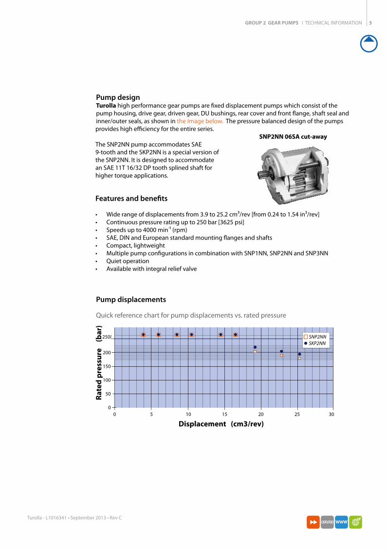
Pump design Turolla high performance gear pumps are fixed displacement pumps which consist of the pump housing, drive gear, driven gear, DU bushings, rear cover and front flange, shaft seal and inner/outer seals, as shown in the image below. The pressure balanced design of the pumps provides high efficiency for the entire series.
The SNP2NN pump accommodates SAE 9-tooth and the SKP2NN is a special version of the SNP2NN. It is designed to accommodate an SAE 11T 16/32 DP tooth splined shaft for higher torque applications.
SNP2NN 06SA cut-away
Features and benefits
• Wide range of displacements from 3.9 to 25.2 cm3/rev [from 0.24 to 1.54 in3/rev] • Continuous pressure rating up to 250 bar [3625 psi] • Speeds up to 4000 min-1 (rpm) • SAE, DIN and European standard mounting flanges and shafts • Compact, lightweight • Multiple pump configurations in combination with SNP1NN, SNP2NN and SNP3NN • Quiet operation • Available with integral relief valve
Pump displacements
Quick reference chart for pump displacements vs. rated pressure
Displacement (cm3/rev)
Rate
d pr
essu
re
(bar
)
200
150
100
50
0
250{
0 5 10 15 20 25 30
SNP2NNSKP2NN
GROUP 2 GEAR PUMPS I TECHNICAL INFORMATION6
Turolla - L1016341 • September 2013 • Rev C
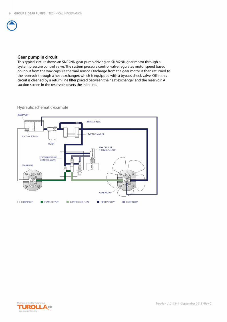
RESERVOIR
BYPASS CHECK
HEAT EXCHANGER
WAX CAPSULETHERMAL SENSOR
SUCTION SCREEN
FILTER
GEAR PUMP
GEAR MOTOR
SYSTEM PRESSURECONTROL VALVE
PUMP INLET PUMP OUTPUT CONTROLLED FLOW RETURN FLOW PILOT FLOW
Gear pump in circuit This typical circuit shows an SNP2NN gear pump driving an SNM2NN gear motor through a system pressure control valve. The system pressure control valve regulates motor speed based on input from the wax capsule thermal sensor. Discharge from the gear motor is then returned to the reservoir through a heat exchanger, which is equipped with a bypass check valve. Oil in this circuit is cleaned by a return line filter placed between the heat exchanger and the reservoir. A suction screen in the reservoir covers the inlet line.
Hydraulic schematic example

GROUP 2 GEAR PUMPS I TECHNICAL INFORMATION
77C33M
55K 50C100Y
66M88Y
66M88Y
7
Turolla - L1016341 • September 2013 • Rev C
Technical Data
Frame size 4,0 6,0 8,0 011 014 017 019 022 025
Displacement cm3/rev[in3/rev]
3.9[0.24]
6.0[0.37]
8.4[0.51]
10.8[0.66]
14.4[0.88]
16.8[1.02]
19.2[1.17]
22.8[1.39]
25.2[1.54]
SNP2NN
Peak pressurebar [psi]
280[4060]
280[4060]
280[4060]
280[4060]
280[4060]
280[4060]
230[3335]
200[2900]
175[2638]
Rated pressure 250[3625]
250[3625]
250[3625]
250[3625]
250[3625]
250[3625]
210[3045]
180[2610]
160[2320]
Minimum speedat 0-100 bar
min-1
(rpm)
600 600 600 500 500 500 500 500 500
Minimum speed at 100-180 bar 1200 1200 1000 800 750 750 700 700 700
Min. speed at 180 bar to rated pressure 1400 1400 1400 1200 1000 1000 1000 800 –
Maximum speed 4000 4000 4000 4000 3500 3000 3000 3000 3000SKP2NN
Peak pressurebar [psi]
280[4060]
280[4060]
280[4060]
280[4060]
280[4060]
280[4060]
260[3770]
230[3335]
200[2900]
Rated pressure 250[3625]
250[3625]
250[3625]
250[3625]
250[3625]
250[3625]
240[3480]
210[3045]
190[2755]
Minimum speedat 0-100 bar
min-1
(rpm)
600 600 600 500 500 500 500 500 500
Minimum speed at 100-180 bar 1200 1200 1000 800 750 750 700 700 700
Min. speed at 180 bar to rated pressure 1400 1400 1400 1200 1000 1000 1000 800 800
Maximum speed 4000 4000 4000 4000 3500 3000 3000 3000 3000Both (SNP2NN, SKP2NN)
Weight kg [lb] 2.3[5.1]
2.4[5.3]
2.5[5.5]
2.7[5.8]
2.9[6.3]
3.0[6.5]
3.1[6.7]
3.2[7.0]
3.3[7.3]
Moment of inertia of rotating components
x 10-6 kg•m2
[x 10-6 lb•ft2]
21.3[505]
26.5[629]
32.4[769]
38.4[911]
47.3[1122]
53.3[1265]
59.2[1405]
68.1[1616]
74.1[1758]
Theoretical flow at maximum speed
l/min[US gal/min]
15.6[4.1]
24.0[6.3]
33.6[8.9]
43.2[11.4]
50.4[13.3]
50.4[13.3]
57.6[15.2]
68.4[18.0]
75.6[20.0]
1 kg•m2 = 23.68 lb•ft2
Caution
The rated and peak pressure mentioned are for pumps with flanged ports only. When threaded ports are required a de-rated performance has to be considered. To verify the compliance of an high pressure application with a threaded ports pump apply to a Turolla representative.
Technical Data
8
Turolla - L1016341 • September 2013 • Rev C
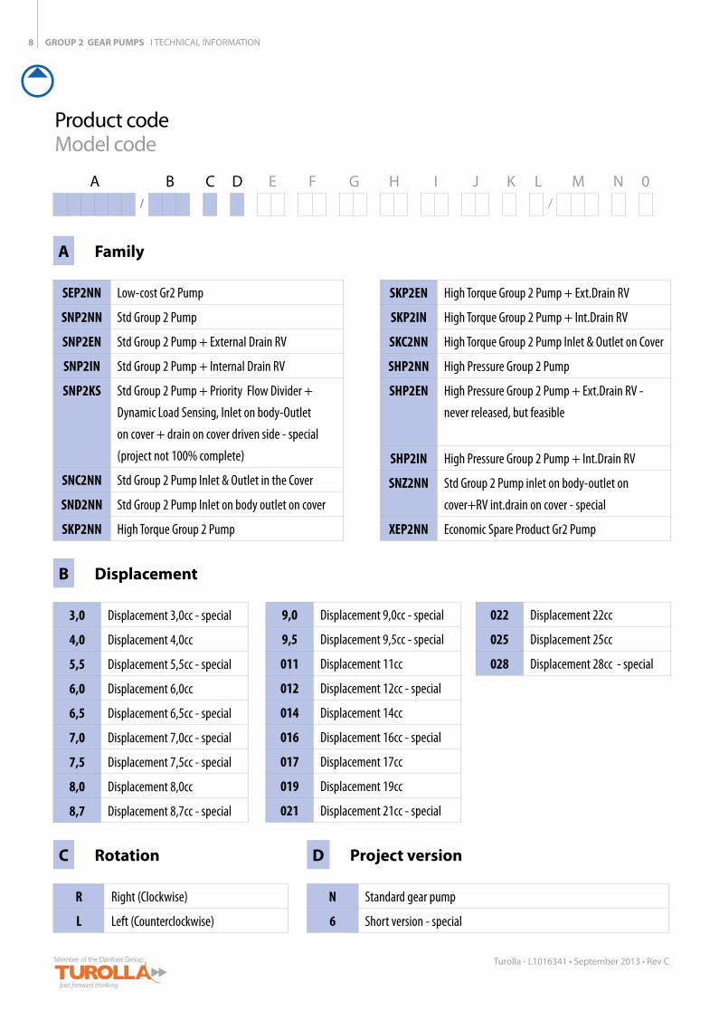
Product codeModel code
GROUP 2 GEAR PUMPS I TECHNICAL INFORMATION
A B C D E F G H I J K L M N 0/ /
A Family
SEP2NN Low-cost Gr2 Pump
SNP2NN Std Group 2 Pump
SNP2EN Std Group 2 Pump + External Drain RV
SNP2IN Std Group 2 Pump + Internal Drain RV
SNP2KS Std Group 2 Pump + Priority Flow Divider +
Dynamic Load Sensing, Inlet on body-Outlet
on cover + drain on cover driven side - special
(project not 100% complete)
SNC2NN Std Group 2 Pump Inlet & Outlet in the Cover
SND2NN Std Group 2 Pump Inlet on body outlet on cover
SKP2NN High Torque Group 2 Pump
B Displacement
3,0 Displacement 3,0cc - special
4,0 Displacement 4,0cc
5,5 Displacement 5,5cc - special
6,0 Displacement 6,0cc
6,5 Displacement 6,5cc - special
7,0 Displacement 7,0cc - special
7,5 Displacement 7,5cc - special
8,0 Displacement 8,0cc
8,7 Displacement 8,7cc - special
C Rotation
R Right (Clockwise)
L Left (Counterclockwise)
D Project version
N Standard gear pump
6 Short version - special
SKP2EN High Torque Group 2 Pump + Ext.Drain RV
SKP2IN High Torque Group 2 Pump + Int.Drain RV
SKC2NN High Torque Group 2 Pump Inlet & Outlet on Cover
SHP2NN High Pressure Group 2 Pump
SHP2EN High Pressure Group 2 Pump + Ext.Drain RV -
never released, but feasible
SHP2IN High Pressure Group 2 Pump + Int.Drain RV
SNZ2NN Std Group 2 Pump inlet on body-outlet on
cover+RV int.drain on cover - special
XEP2NN Economic Spare Product Gr2 Pump
9,0 Displacement 9,0cc - special
9,5 Displacement 9,5cc - special
011 Displacement 11cc
012 Displacement 12cc - special
014 Displacement 14cc
016 Displacement 16cc - special
017 Displacement 17cc
019 Displacement 19cc
021 Displacement 21cc - special
022 Displacement 22cc
025 Displacement 25cc
028 Displacement 28cc - special
77C33M
55K 50C100Y
66M88Y
66M88Y
9
Turolla - L1016341 • September 2013 • Rev C
GROUP 2 GEAR PUMPS I TECHNICAL INFORMATION
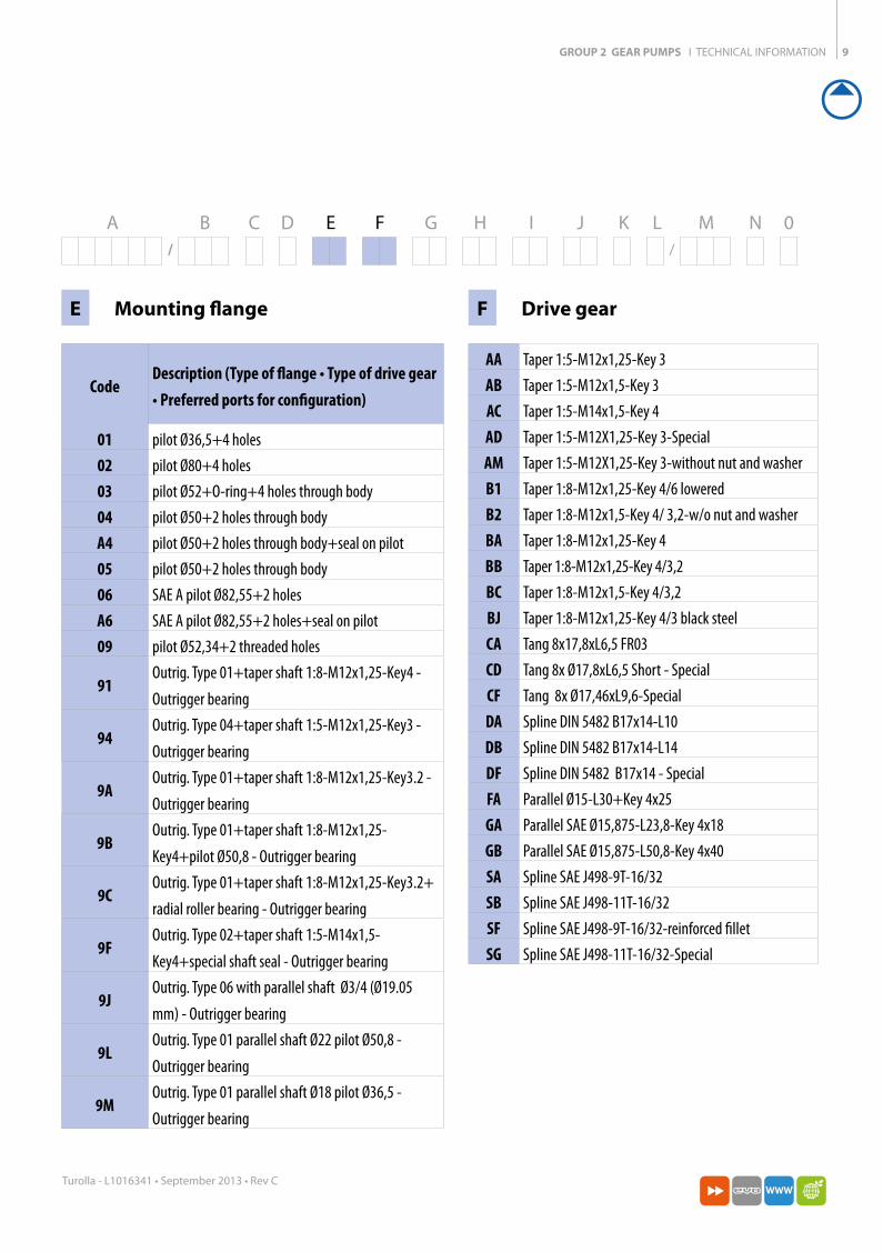
A B C D E F G H I J K L M N 0/ /
E Mounting flange
CodeDescription (Type of flange • Type of drive gear • Preferred ports for configuration)
01 pilot Ø36,5+4 holes 02 pilot Ø80+4 holes 03 pilot Ø52+O-ring+4 holes through body04 pilot Ø50+2 holes through bodyA4 pilot Ø50+2 holes through body+seal on pilot05 pilot Ø50+2 holes through body06 SAE A pilot Ø82,55+2 holes A6 SAE A pilot Ø82,55+2 holes+seal on pilot09 pilot Ø52,34+2 threaded holes
91Outrig. Type 01+taper shaft 1:8-M12x1,25-Key4 -
Outrigger bearing
94Outrig. Type 04+taper shaft 1:5-M12x1,25-Key3 -
Outrigger bearing
9AOutrig. Type 01+taper shaft 1:8-M12x1,25-Key3.2 -
Outrigger bearing
9BOutrig. Type 01+taper shaft 1:8-M12x1,25-
Key4+pilot Ø50,8 - Outrigger bearing
9COutrig. Type 01+taper shaft 1:8-M12x1,25-Key3.2+
radial roller bearing - Outrigger bearing
9FOutrig. Type 02+taper shaft 1:5-M14x1,5-
Key4+special shaft seal - Outrigger bearing
9JOutrig. Type 06 with parallel shaft Ø3/4 (Ø19.05
mm) - Outrigger bearing
9LOutrig. Type 01 parallel shaft Ø22 pilot Ø50,8 -
Outrigger bearing
9MOutrig. Type 01 parallel shaft Ø18 pilot Ø36,5 -
Outrigger bearing
F Drive gear
AA Taper 1:5-M12x1,25-Key 3AB Taper 1:5-M12x1,5-Key 3AC Taper 1:5-M14x1,5-Key 4AD Taper 1:5-M12X1,25-Key 3-SpecialAM Taper 1:5-M12X1,25-Key 3-without nut and washerB1 Taper 1:8-M12x1,25-Key 4/6 loweredB2 Taper 1:8-M12x1,5-Key 4/ 3,2-w/o nut and washerBA Taper 1:8-M12x1,25-Key 4BB Taper 1:8-M12x1,25-Key 4/3,2BC Taper 1:8-M12x1,5-Key 4/3,2BJ Taper 1:8-M12x1,25-Key 4/3 black steelCA Tang 8x17,8xL6,5 FR03CD Tang 8x Ø17,8xL6,5 Short - SpecialCF Tang 8x Ø17,46xL9,6-SpecialDA Spline DIN 5482 B17x14-L10DB Spline DIN 5482 B17x14-L14DF Spline DIN 5482 B17x14 - SpecialFA Parallel Ø15-L30+Key 4x25GA Parallel SAE Ø15,875-L23,8-Key 4x18GB Parallel SAE Ø15,875-L50,8-Key 4x40SA Spline SAE J498-9T-16/32SB Spline SAE J498-11T-16/32SF Spline SAE J498-9T-16/32-reinforced filletSG Spline SAE J498-11T-16/32-Special
10
Turolla - L1016341 • September 2013 • Rev C
GROUP 2 GEAR PUMPS I TECHNICAL INFORMATION
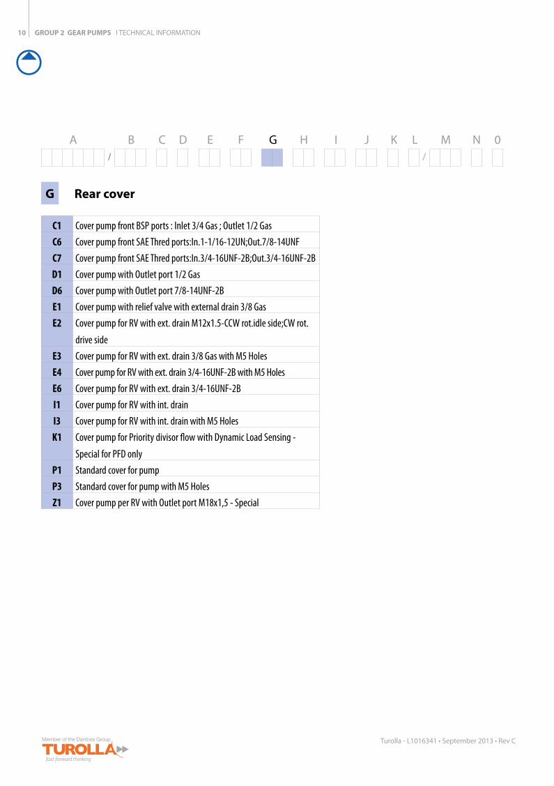
A B C D E F G H I J K L M N 0/ /
G Rear cover
C1 Cover pump front BSP ports : Inlet 3/4 Gas ; Outlet 1/2 Gas C6 Cover pump front SAE Thred ports:In.1-1/16-12UN;Out.7/8-14UNFC7 Cover pump front SAE Thred ports:In.3/4-16UNF-2B;Out.3/4-16UNF-2BD1 Cover pump with Outlet port 1/2 GasD6 Cover pump with Outlet port 7/8-14UNF-2BE1 Cover pump with relief valve with external drain 3/8 GasE2 Cover pump for RV with ext. drain M12x1.5-CCW rot.idle side;CW rot.
drive sideE3 Cover pump for RV with ext. drain 3/8 Gas with M5 HolesE4 Cover pump for RV with ext. drain 3/4-16UNF-2B with M5 HolesE6 Cover pump for RV with ext. drain 3/4-16UNF-2BI1 Cover pump for RV with int. drain I3 Cover pump for RV with int. drain with M5 HolesK1 Cover pump for Priority divisor flow with Dynamic Load Sensing -
Special for PFD onlyP1 Standard cover for pumpP3 Standard cover for pump with M5 HolesZ1 Cover pump per RV with Outlet port M18x1,5 - Special
77C33M
55K 50C100Y
66M88Y
66M88Y
11
Turolla - L1016341 • September 2013 • Rev C
GROUP 2 GEAR PUMPS I TECHNICAL INFORMATION
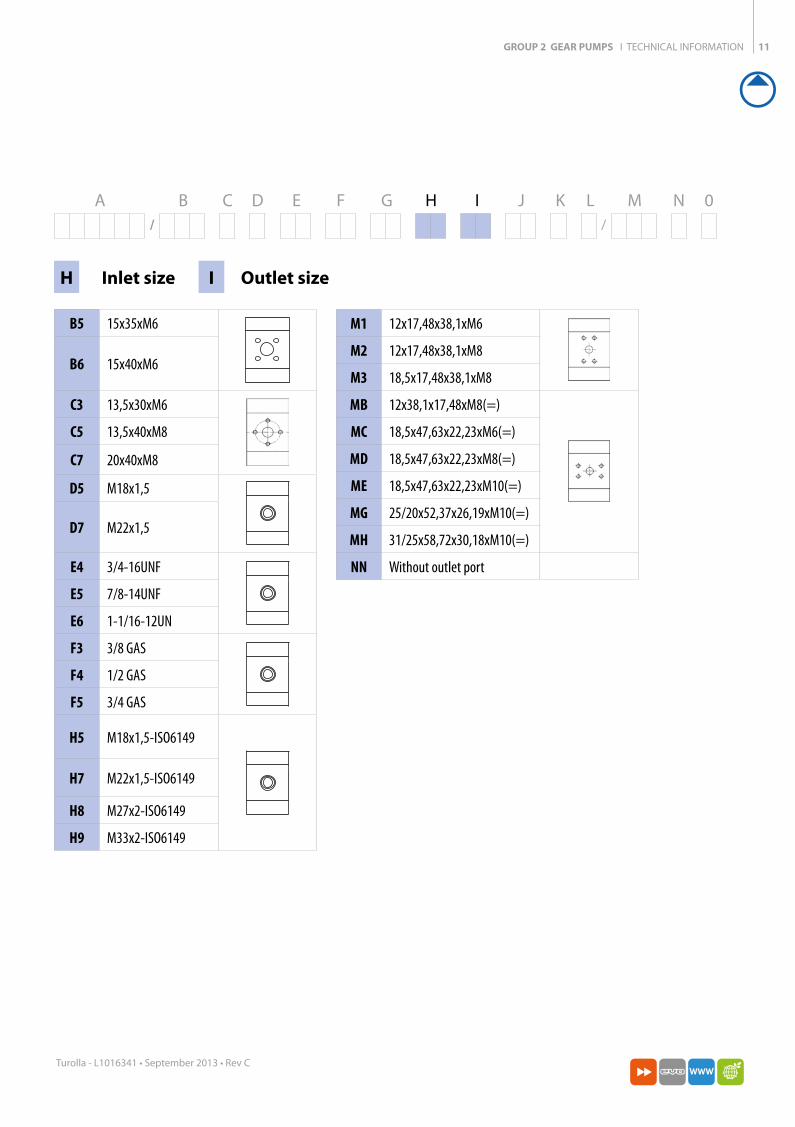
A B C D E F G H I J K L M N 0/ /
M1 12x17,48x38,1xM6
M2 12x17,48x38,1xM8
M3 18,5x17,48x38,1xM8
MB 12x38,1x17,48xM8(=)
MC 18,5x47,63x22,23xM6(=)
MD 18,5x47,63x22,23xM8(=)
ME 18,5x47,63x22,23xM10(=)
MG 25/20x52,37x26,19xM10(=)
MH 31/25x58,72x30,18xM10(=)
NN Without outlet port
H Inlet size I Outlet size
B5 15x35xM6
B6 15x40xM6
C3 13,5x30xM6
C5 13,5x40xM8
C7 20x40xM8
D5 M18x1,5
D7 M22x1,5
E4 3/4-16UNF
E5 7/8-14UNF
E6 1-1/16-12UN
F3 3/8 GAS
F4 1/2 GAS
F5 3/4 GAS
H5 M18x1,5-ISO6149
H7 M22x1,5-ISO6149
H8 M27x2-ISO6149
H9 M33x2-ISO6149
GROUP 2 GEAR PUMPS I TECHNICAL INFORMATION12
Turolla - L1016341 • September 2013 • Rev C
A B C D E F G H I J K L M N 0/ /
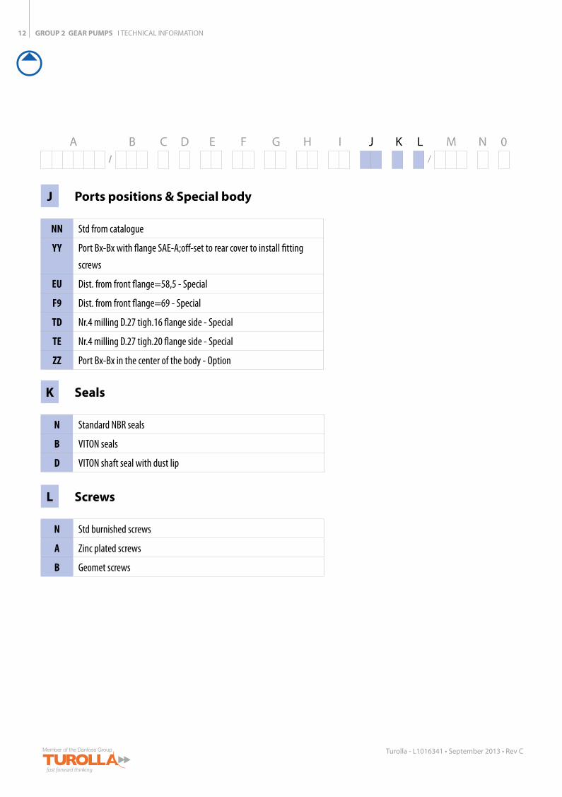
J Ports positions & Special body
NN Std from catalogue
YY Port Bx-Bx with flange SAE-A;off-set to rear cover to install fitting
screws
EU Dist. from front flange=58,5 - Special
F9 Dist. from front flange=69 - Special
TD Nr.4 milling D.27 tigh.16 flange side - Special
TE Nr.4 milling D.27 tigh.20 flange side - Special
ZZ Port Bx-Bx in the center of the body - Option
K Seals
N Standard NBR seals
B VITON seals
D VITON shaft seal with dust lip
L Screws
N Std burnished screws
A Zinc plated screws
B Geomet screws
GROUP 2 GEAR PUMPS I TECHNICAL INFORMATION
77C33M
55K 50C100Y
66M88Y
66M88Y
13
Turolla - L1016341 • September 2013 • Rev C
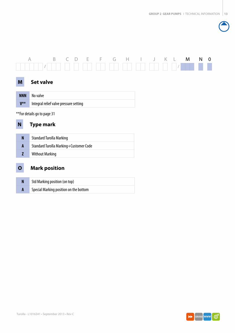
M Set valve
NNN No valve
V** Integral relief valve pressure setting
**For details go to page 31
A B C D E F G H I J K L M N 0/ /
N Type mark
N Standard Turolla Marking
A Standard Turolla Marking+Customer Code
Z Without Marking
O Mark position
N Std Marking position (on top)
A Special Marking position on the bottom
GROUP 2 GEAR PUMPS I TECHNICAL INFORMATION14
Turolla - L1016341 • September 2013 • Rev C
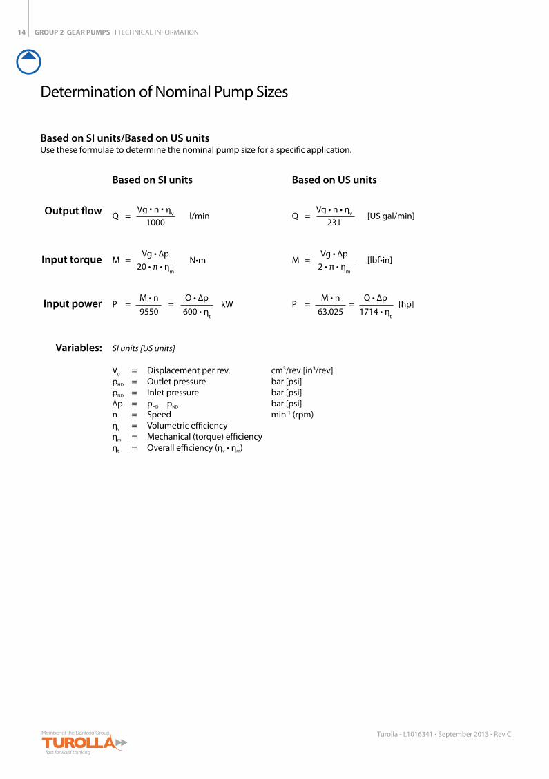
Determination of Nominal Pump Sizes
Based on SI units/Based on US units Use these formulae to determine the nominal pump size for a specific application.
Based on SI units
Output flow
Input torque
Input power
Variables:
Vg • n • ηvQ = l/min 1000
Vg • ∆pM = N•m 20 • π • η
m
M • n Q • ∆pP = = kW 9550 600 • η
t
SI units [US units]
Vg = Displacement per rev. cm3/rev [in3/rev]pHD = Outlet pressure bar [psi]pND = Inlet pressure bar [psi]∆p = pHD – pND bar [psi]n = Speed min-1 (rpm)ηv = Volumetric efficiencyηm = Mechanical (torque) efficiencyηt = Overall efficiency (ηv • ηm)
Vg • n • ηvQ = [US gal/min] 231
Vg • ∆pM = [lbf•in] 2 • π • η
m
M • n Q • ∆pP = = [hp] 63.025 1714 • η
t
Based on US units
77C33M
55K 50C100Y
66M88Y
66M88Y
15
Turolla - L1016341 • September 2013 • Rev C
System Requirements
GROUP 2 GEAR PUMPS I TECHNICAL INFORMATION
Pres
sure
0
SpeedMax
OperatingEnvelope
N10 N2 N3
P1
P2
Rated pressure
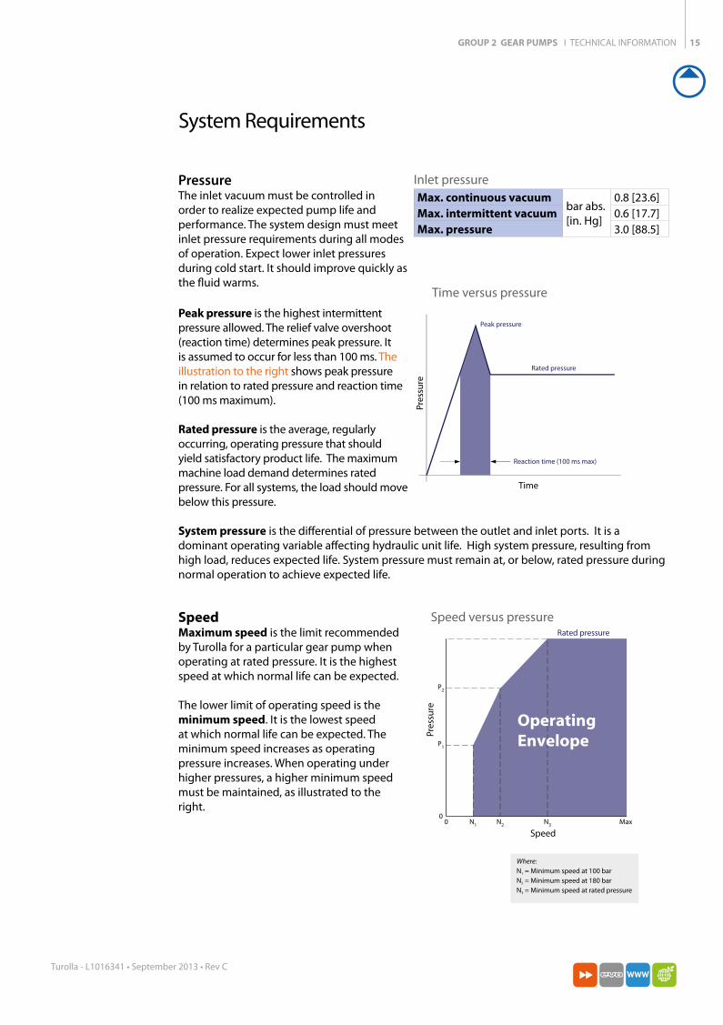
Where:N
1 = Minimum speed at 100 bar
N2 = Minimum speed at 180 bar
N3 = Minimum speed at rated pressure
Where:N1 = Minimum speed at 100 barN2 = Minimum speed at 180 barN3 = Minimum speed at rated pressure
SpeedMaximum speed is the limit recommended by Turolla for a particular gear pump when operating at rated pressure. It is the highest speed at which normal life can be expected.
The lower limit of operating speed is the minimum speed. It is the lowest speed at which normal life can be expected. The minimum speed increases as operating pressure increases. When operating under higher pressures, a higher minimum speed must be maintained, as illustrated to the right.
PressureThe inlet vacuum must be controlled in order to realize expected pump life and performance. The system design must meet inlet pressure requirements during all modes of operation. Expect lower inlet pressures during cold start. It should improve quickly as the fluid warms.
Peak pressure is the highest intermittent pressure allowed. The relief valve overshoot (reaction time) determines peak pressure. It is assumed to occur for less than 100 ms. The illustration to the right shows peak pressure in relation to rated pressure and reaction time (100 ms maximum).
Rated pressure is the average, regularly occurring, operating pressure that should yield satisfactory product life. The maximum machine load demand determines rated pressure. For all systems, the load should move below this pressure.
Peak pressure
Rated pressure
Reaction time (100 ms max)
Time
Pres
sure
Time versus pressure
Speed versus pressure
Inlet pressureMax. continuous vacuum
bar abs.[in. Hg]
0.8 [23.6]Max. intermittent vacuum 0.6 [17.7]Max. pressure 3.0 [88.5]
System pressure is the differential of pressure between the outlet and inlet ports. It is a dominant operating variable affecting hydraulic unit life. High system pressure, resulting from high load, reduces expected life. System pressure must remain at, or below, rated pressure during normal operation to achieve expected life.
GROUP 2 GEAR PUMPS I TECHNICAL INFORMATION16
Turolla - L1016341 • September 2013 • Rev C
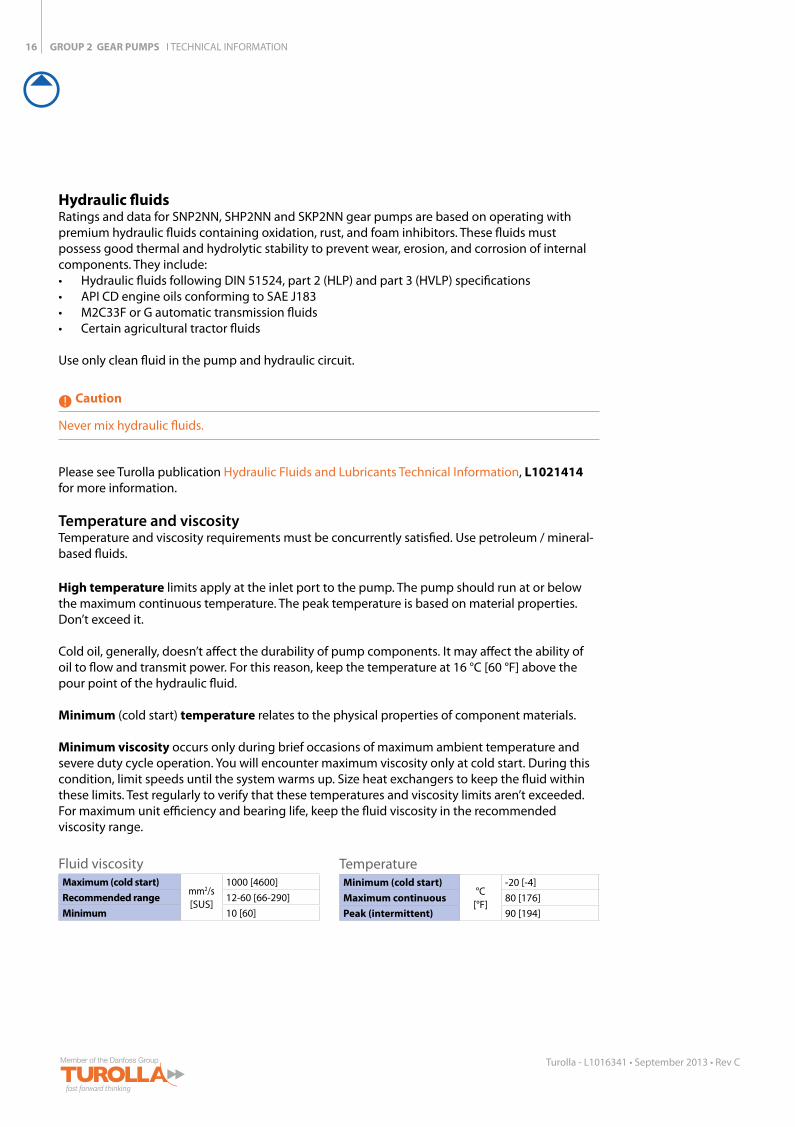
Temperature and viscosityTemperature and viscosity requirements must be concurrently satisfied. Use petroleum / mineral-based fluids.
High temperature limits apply at the inlet port to the pump. The pump should run at or below the maximum continuous temperature. The peak temperature is based on material properties. Don’t exceed it.
Cold oil, generally, doesn’t affect the durability of pump components. It may affect the ability of oil to flow and transmit power. For this reason, keep the temperature at 16 °C [60 °F] above the pour point of the hydraulic fluid.
Minimum (cold start) temperature relates to the physical properties of component materials.
Minimum viscosity occurs only during brief occasions of maximum ambient temperature and severe duty cycle operation. You will encounter maximum viscosity only at cold start. During this condition, limit speeds until the system warms up. Size heat exchangers to keep the fluid within these limits. Test regularly to verify that these temperatures and viscosity limits aren’t exceeded. For maximum unit efficiency and bearing life, keep the fluid viscosity in the recommended viscosity range.
TemperatureMinimum (cold start)
°C[°F]
-20 [-4]Maximum continuous 80 [176]Peak (intermittent) 90 [194]
Fluid viscosityMaximum (cold start)
mm2/s[SUS]
1000 [4600]Recommended range 12-60 [66-290]Minimum 10 [60]
Hydraulic fluidsRatings and data for SNP2NN, SHP2NN and SKP2NN gear pumps are based on operating with premium hydraulic fluids containing oxidation, rust, and foam inhibitors. These fluids must possess good thermal and hydrolytic stability to prevent wear, erosion, and corrosion of internal components. They include: • Hydraulic fluids following DIN 51524, part 2 (HLP) and part 3 (HVLP) specifications • API CD engine oils conforming to SAE J183 • M2C33F or G automatic transmission fluids • Certain agricultural tractor fluids
Use only clean fluid in the pump and hydraulic circuit.
Caution
Never mix hydraulic fluids.
Please see Turolla publication Hydraulic Fluids and Lubricants Technical Information, L1021414 for more information.
GROUP 2 GEAR PUMPS I TECHNICAL INFORMATION
77C33M
55K 50C100Y
66M88Y
66M88Y
17
Turolla - L1016341 • September 2013 • Rev C
Filtration
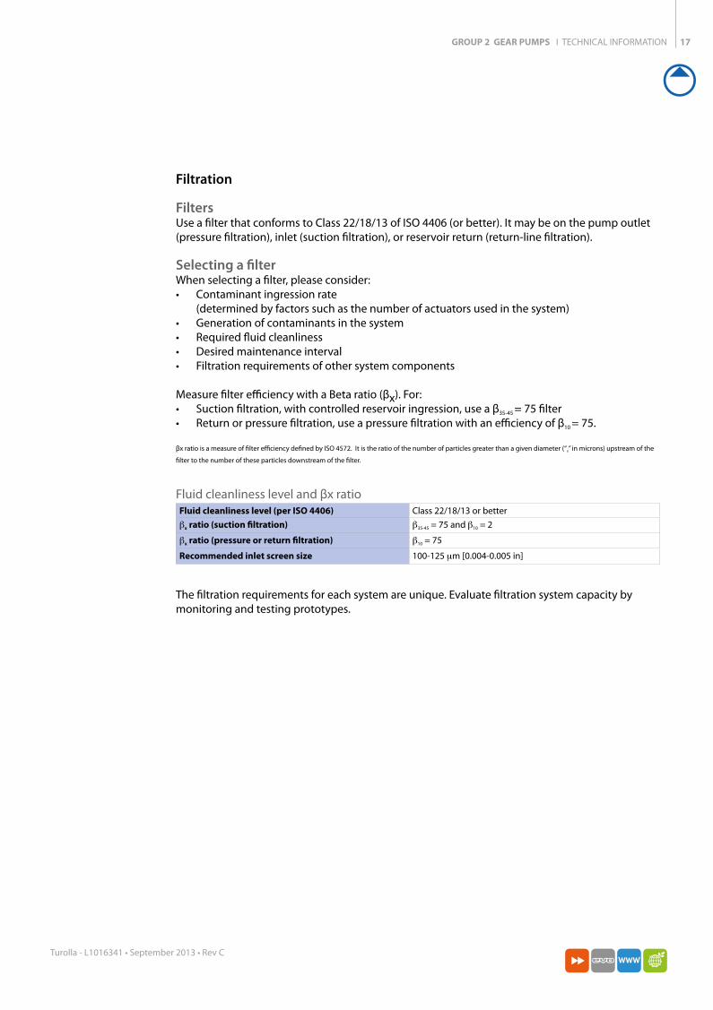
FiltersUse a filter that conforms to Class 22/18/13 of ISO 4406 (or better). It may be on the pump outlet (pressure filtration), inlet (suction filtration), or reservoir return (return-line filtration).
Selecting a filterWhen selecting a filter, please consider: • Contaminant ingression rate
(determined by factors such as the number of actuators used in the system) • Generation of contaminants in the system • Required fluid cleanliness • Desired maintenance interval • Filtration requirements of other system components
Measure filter efficiency with a Beta ratio (βx). For: • Suction filtration, with controlled reservoir ingression, use a β35-45 = 75 filter • Return or pressure filtration, use a pressure filtration with an efficiency of β10 = 75.
βx ratio is a measure of filter efficiency defined by ISO 4572. It is the ratio of the number of particles greater than a given diameter (“x” in microns) upstream of the
filter to the number of these particles downstream of the filter.
Fluid cleanliness level and βx ratioFluid cleanliness level (per ISO 4406) Class 22/18/13 or betterβx ratio (suction filtration) β35-45 = 75 and β10 = 2
βx ratio (pressure or return filtration) β10 = 75
Recommended inlet screen size 100-125 µm [0.004-0.005 in]
The filtration requirements for each system are unique. Evaluate filtration system capacity by monitoring and testing prototypes.
GROUP 2 GEAR PUMPS I TECHNICAL INFORMATION18
Turolla - L1016341 • September 2013 • Rev C
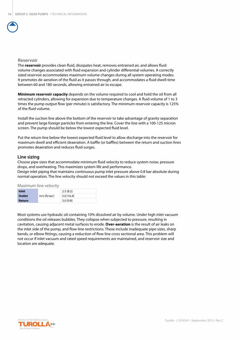
Line sizingChoose pipe sizes that accommodate minimum fluid velocity to reduce system noise, pressure drops, and overheating. This maximizes system life and performance. Design inlet piping that maintains continuous pump inlet pressure above 0.8 bar absolute during normal operation. The line velocity should not exceed the values in this table:
Maximum line velocityInlet
m/s [ft/sec]2.5 [8.2]
Outlet 5.0 [16.4]Return 3.0 [9.8]
Most systems use hydraulic oil containing 10% dissolved air by volume. Under high inlet vacuum conditions the oil releases bubbles. They collapse when subjected to pressure, resulting in cavitation, causing adjacent metal surfaces to erode. Over-aeration is the result of air leaks on the inlet side of the pump, and flow-line restrictions. These include inadequate pipe sizes, sharp bends, or elbow fittings, causing a reduction of flow line cross sectional area. This problem will not occur if inlet vacuum and rated speed requirements are maintained, and reservoir size and location are adequate.
Reservoir The reservoir provides clean fluid, dissipates heat, removes entrained air, and allows fluid volume changes associated with fluid expansion and cylinder differential volumes. A correctly sized reservoir accommodates maximum volume changes during all system operating modes. It promotes de-aeration of the fluid as it passes through, and accommodates a fluid dwell-time between 60 and 180 seconds, allowing entrained air to escape.
Minimum reservoir capacity depends on the volume required to cool and hold the oil from all retracted cylinders, allowing for expansion due to temperature changes. A fluid volume of 1 to 3 times the pump output flow (per minute) is satisfactory. The minimum reservoir capacity is 125% of the fluid volume.
Install the suction line above the bottom of the reservoir to take advantage of gravity separation and prevent large foreign particles from entering the line. Cover the line with a 100-125 micron screen. The pump should be below the lowest expected fluid level.
Put the return-line below the lowest expected fluid level to allow discharge into the reservoir for maximum dwell and efficient deaeration. A baffle (or baffles) between the return and suction lines promotes deaeration and reduces fluid surges.

GROUP 2 GEAR PUMPS I TECHNICAL INFORMATION
77C33M
55K 50C100Y
66M88Y
66M88Y
19
Turolla - L1016341 • September 2013 • Rev C
Pilot cavity
Ø 0.1 [0.004]
P101 002E
Mating spline
Plug-in drives, acceptable only with a splined shaft, can impose severe radial loads when the mating spline is rigidly supported. Increasing spline clearance does not alleviate this condition.
Use plug-in drives if the concentricity between the mating spline and pilot diameter is within 0.1 mm [0.004 in]. Lubricate the drive by flooding it with oil. A 3-piece coupling minimizes radial or thrust shaft loads.
Caution
In order to avoid spline shaft damages it is recommended to use carburized and hardened steel couplings with 80-82 HRA surface hardness.
Allowable radial shaft loads are a function of the load position, load orientation, and operating pressure of the hydraulic pump. All external shaft loads have an effect on bearing life, and may affect pump performance.
In applications where external shaft loads can’t be avoided, minimize the impact on the pump by optimizing the orientation and magnitude of the load. Use a tapered input shaft; don’t use splined shafts for belt or gear drive applications. A spring-loaded belt tension-device is recommended for belt drive applications to avoid excessive tension. Avoid thrust loads in either direction. Contact Turolla if continuously applied external radial or thrust loads occur.
Pump driveShaft options for Group 2 gear pumps include tapered, tang, splined, or parallel shafts. They are suitable for a wide range of direct and indirect drive applications for radial and thrust loads.
GROUP 2 GEAR PUMPS I TECHNICAL INFORMATION20
Turolla - L1016341 • September 2013 • Rev C
90o
α a
0o
270o
180o 0o
Inlet port Inlet port
a
dw
270o
180o
90o
dw
a
P
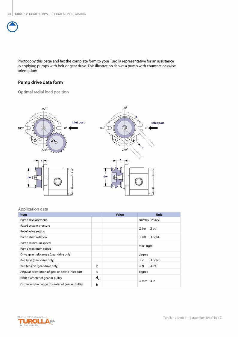
Application dataItem Value Unit
Pump displacement cm3/rev [in3/rev]
Rated system pressure bar psi
Relief valve setting
Pump shaft rotation left right
Pump minimum speedmin-1 (rpm)
Pump maximum speed
Drive gear helix angle (gear drive only) degree
Belt type (gear drive only) V notch
Belt tension (gear drive only) P N lbf
Angular orientation of gear or belt to inlet port α degree
Pitch diameter of gear or pulley dw mm in
Distance from flange to center of gear or pulley a
Pump drive data form
Optimal radial load position
Photocopy this page and fax the complete form to your Turolla representative for an assistance in applying pumps with belt or gear drive. This illustration shows a pump with counterclockwise orientation:
GROUP 2 GEAR PUMPS I TECHNICAL INFORMATION
77C33M
55K 50C100Y
66M88Y
66M88Y
21
Turolla - L1016341 • September 2013 • Rev C
Pump lifePump life is a function of speed, system pressure, and other system parameters (such as fluid quality and cleanliness).
All Turolla gear pumps use hydrodynamic journal bearings that have an oil film maintained between the gear/shaft and bearing surfaces at all times. If the oil film is sufficiently sustained through proper system maintenance and operating within recommended limits, long life can be expected.
B10 life expectancy number is generally associated with rolling element bearings. It does not exist for hydrodynamic bearings.
High pressure, resulting from high loads, impacts pump life. When submitting an application for review, provide machine duty cycle data that includes percentages of time at various loads and speeds. We strongly recommend a prototype testing program to verify operating parameters and their impact on life expectancy before finalizing any system design.

GROUP 2 GEAR PUMPS I TECHNICAL INFORMATION22
Turolla - L1016341 • September 2013 • Rev C
Sound levelsFluid power systems are inherent generators of noise. As with many high power density devices, noise is an unwanted side affect. However, there are many techniques available to minimize noise from fluid power systems. To apply these methods effectively, it is necessary to understand how the noise is generated and how it reaches the listener. The noise energy can be transmitted away from its source as either fluid borne noise (pressure ripple) or as structure borne noise.
Pressure ripple is the result of the number of pumping elements (gear teeth) delivering oil to the outlet and the pump’s ability to gradually change the volume of each pumping element from low to high pressure. In addition, the pressure ripple is affected by the compressibility of the oil as each pumping element discharges into the outlet of the pump. Pressure pulsations will travel along the hydraulic lines at the speed of sound (about 1400 m/s in oil) until affected by a change in the system such as an elbow fitting. Thus the pressure pulsation amplitude varies with overall line length and position.
Structure borne noise may be transmitted wherever the pump casing is connected to the rest of the system. The manner in which one circuit component responds to excitation depends on its size, form, and manner in which it is mounted or supported. Because of this excitation, a system line may actually have a greater noise level than the pump. To reduce this excitation, use flexible hoses in place of steel plumbing. If steel plumbing must be used, clamping of lines is recommended. To minimize other structure borne noise, use flexible (rubber) mounts.
The accompanying graph shows typical sound pressure levels for SNP2NN pumps (with SAE A flange, and spline shaft in plug in drive) measured in dB (A) at 1 m [3.28 ft] from the unit in a semi-anechoic chamber. Anechoic levels can be estimated by subtracting 3 dB (A) from these values.
Contact your Turolla representative for assistance with system noise control.
10 15 20 25 30
80
75
70
65
60
55
Displacement (cc/rev)
Sou
nd
pre
ssu
re le
vel (
dB
(A) a
t 1
m [3
.3ft
])
1800 rpm, 175 bar [2538 psi]3000 rpm, 175 bar [2538 psi]1800 rpm, 250 bar [3626 psi]3000 rpm, 250 bar [3626 psi]
50
Sound levels graph
GROUP 2 GEAR PUMPS I TECHNICAL INFORMATION
77C33M
55K 50C100Y
66M88Y
66M88Y
23
Turolla - L1016341 • September 2013 • Rev C
Pump Performance
0 40001000 2000 3000
16
14
12
10
8
6
4
2
8
6
4
2
Flow
l/
min
[US
gal/m
in]
Pow
er
kW [H
P][4.0]
[0.5]
[1.0]
[1.5]
[2.0]
[2.5]
[3.0]
[3.5]
0
[2]
[4]
[6]
[8]
[10]
[12]
Speed min-1 (rpm)
0
SNP2NN, SKP2NN/4,0
250 bar
150 bar
100 bar 2
4
6
8
10
12
0
[2]
[4]
[6]
[8]
[10]
[12]
[14]
[16]
0 40001000 2000 3000
150 bar
100 bar
26
6
8
10
12
14
16
18
20
22
24[6.5]
[1.5]
[1.0]
[2.0]
[2.5]
[3.0]
[3.5]
[4.0]
[4.5]
[5.0]
[5.5]
[6.0]
4
2[0.5]
0
SNP2NN, SKP2NN/6,0
150 bar
100 bar
250 bar
Flow
l/
min
[US
gal/m
in]
Pow
er
kW [H
P]
Speed min-1 (rpm)
35
5
10
15
20
25
30
5
10
15
0 40001000 2000 3000
[9]
[1]
[2]
[3]
[4]
[5]
[6]
[7]
[8]
0
[5]
[10]
[15]
[20]
0
SNP2NN, SKP2NN/8,0
250 bar
150 bar
100 bar
Flow
l/
min
[US
gal/m
in]
Pow
er
kW [H
P]
Speed min-1 (rpm)
5
10
15
20
0
[25]
[30]
0 40001000 2000 3000
250 bar
150 bar
100 bar
50
5
10
15
20
25
30
35
40
45
[13]
[10]
[11]
[12]
0
SNP2NN, SKP2NN/011
250 bar
150 bar
100 bar
Flow
l/
min
[US
gal/m
in]
Pow
er
kW [H
P]
Speed min-1 (rpm)
[9]
[1]
[2]
[3]
[4]
[5]
[6]
[7]
[8]
[5]
[10]
[15]
[20]
250 b
ar
7 bar
250 b
ar
7 bar
250 b
ar
7 bar
250 b
ar
7 bar
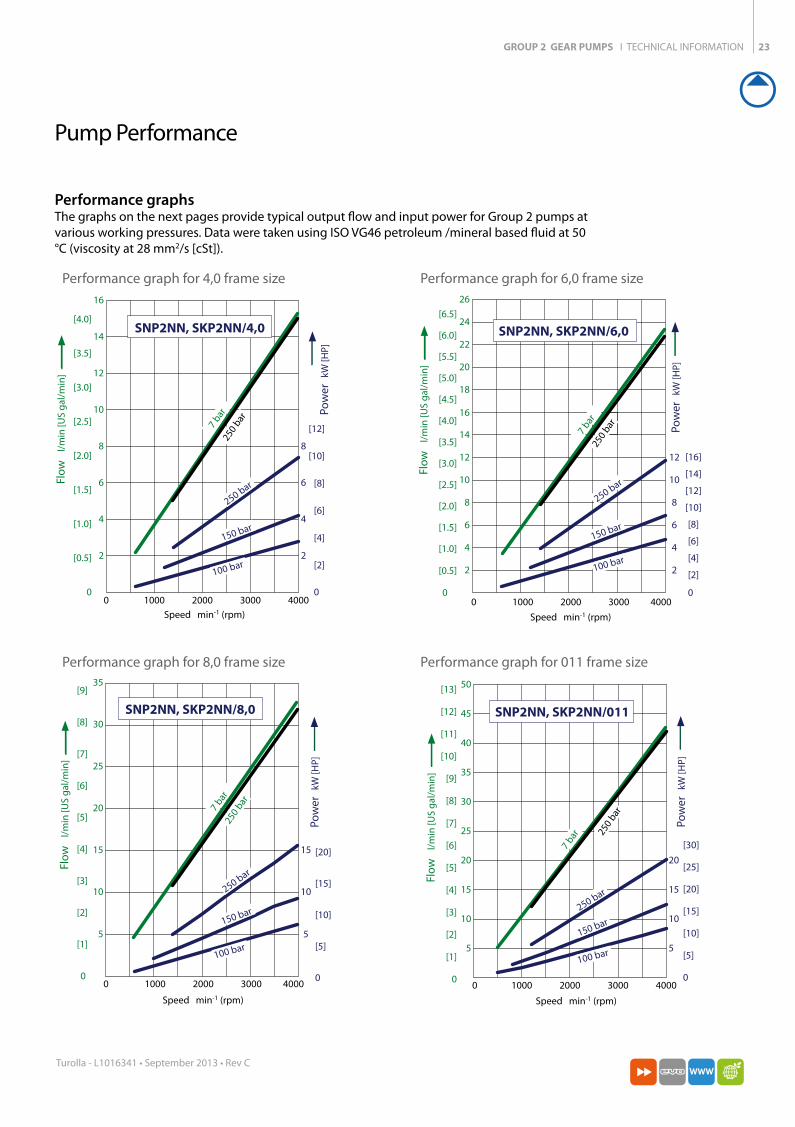
Performance graphsThe graphs on the next pages provide typical output flow and input power for Group 2 pumps at various working pressures. Data were taken using ISO VG46 petroleum /mineral based fluid at 50 °C (viscosity at 28 mm2/s [cSt]).
Performance graph for 4,0 frame size Performance graph for 6,0 frame size
Performance graph for 8,0 frame size Performance graph for 011 frame size
GROUP 2 GEAR PUMPS I TECHNICAL INFORMATION24
Turolla - L1016341 • September 2013 • Rev C
5
10
15
20
25
0
[35]
0 500 1500 2500 3500
50
5
10
15
20
25
30
35
40
45
250
bar
7 ba
r
SNP2NN, SKP2NN/014
250 bar
150 bar
100 bar
[25]
[30]
[13]
[10]
[11]
[12]
0
Flow
l/
min
[US
gal
/min
]
Po
wer
kW
[HP]
Speed min-1 (rpm)
[9]
[1]
[2]
[3]
[4]
[5]
[6]
[7]
[8]
[5]
[10]
[15]
[20]
0 1000 2000 3000
150 bar
250
bar
7 ba
r
SNP2/SKP2 17ccSNP2NN, SKP2NN/017
5
10
15
20
25
0
[35]
50
5
10
15
20
25
30
35
40
45
[25]
[30]
[13]
[10]
[11]
[12]
0
Flow
l/
min
[US
gal
/min
]
Po
wer
kW
[HP]
Speed min-1 (rpm)
[9]
[1]
[2]
[3]
[4]
[5]
[6]
[7]
[8]
[5]
[10]
[15]
[20]
100 bar
250 bar
5
10
15
20
25
30
0 1000 2000 3000
[40]
[45]
210 bar
150 bar
100 bar
60
5
10
15
20
25
30
35
40
45
50
55[15]
[14]
210
bar7
bar
SNP2NN, SKP2NN/019
0
[35]
[25]
[30]
[13]
[10]
[11]
[12]
0
Flow
l/
min
[US
gal
/min
]
Po
wer
kW
[HP]
Speed min-1 (rpm)
[9]
[1]
[2]
[3]
[4]
[5]
[6]
[7]
[8]
[5]
[10]
[15]
[20]
70
10
15
20
25
30
35
40
45
50
55
60
65
4
8
12
16
20
24
0 1000 2000 3000
[18]
[14]
[15]
[16]
[17]
100 bar
5
SNP2NN, SKP2NN/022
150 bar
180 bar
0
[35]
[25]
[30]
[13]
[10]
[11]
[12]
0
Flow
l/
min
[US
gal
/min
]
Po
wer
kW
[HP]
Speed min-1 (rpm)
[9]
[1]
[2]
[3]
[4]
[5]
[6]
[7]
[8]
[5]
[10]
[15]
[20]
180
bar7
bar
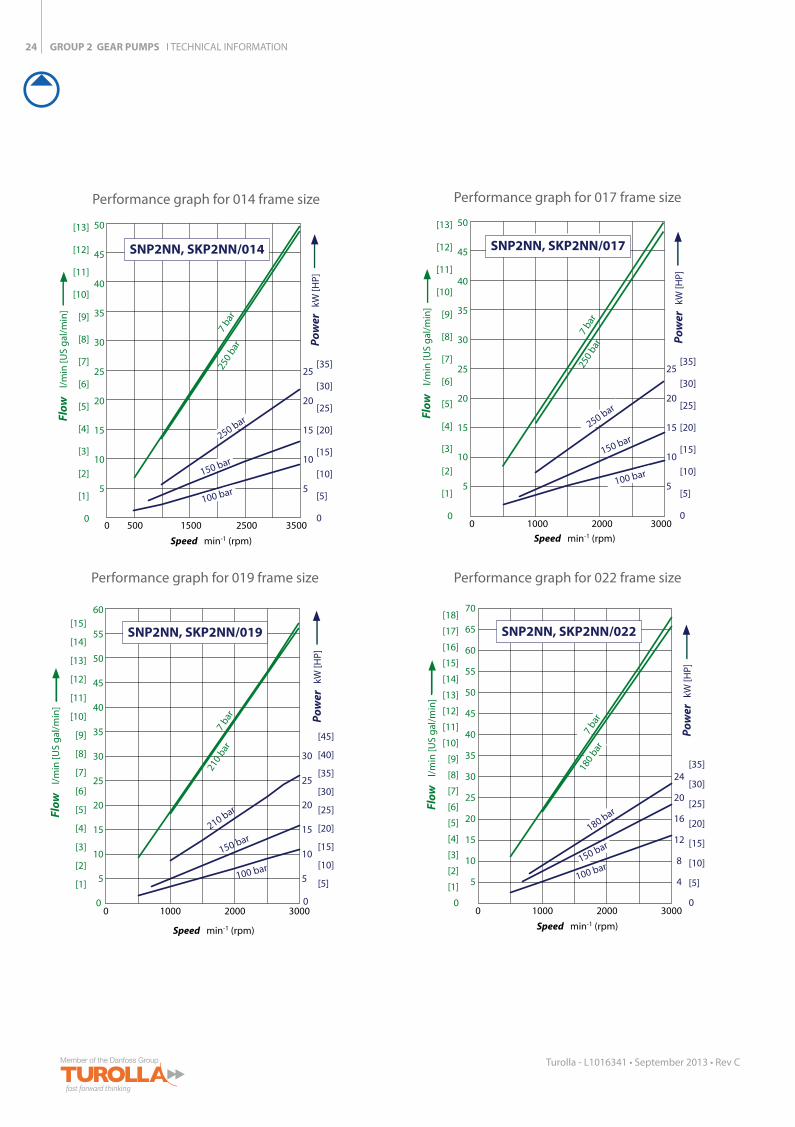
Performance graph for 014 frame size Performance graph for 017 frame size
Performance graph for 019 frame size Performance graph for 022 frame size

GROUP 2 GEAR PUMPS I TECHNICAL INFORMATION
77C33M
55K 50C100Y
66M88Y
66M88Y
25
Turolla - L1016341 • September 2013 • Rev C
80
10
20
30
40
60
70
50
10
20
30
0 1000 2000 3000
[20]
0
[40]
160 bar
100 bar
SNP2NN, SKP2NN/025
[30]
[18]
[10]
[16]
[12]
0
Flow
l/
min
[US
gal
/min
]
Po
wer
kW
[HP]
Speed min-1 (rpm)
[14]
[2]
[4]
[6]
[8]
[10]
[20]
160
bar
7 bar
5
10
15
20
25
30
0 1000 2000 30000
60
5
10
15
20
25
30
35
40
45
50
55
0
SHP2NN/019
240 bar
150 bar
100 bar
[40]
[30]
[10]
[16]
[12]
Flo
w
l/m
in [U
S g
al/m
in]
Po
wer
kW
[HP]
Speed min-1 (rpm)
[14]
[2]
[4]
[6]
[8]
[10]
[20]
240
bar
7 bar
70
10
15
20
25
30
35
40
45
50
55
60
65
0 1000 2000 3000
5
SHP2NN/022
210 bar
150 bar
100 bar
210
bar
4
8
12
16
20
24
[18]
[14]
[15]
[16]
[17]
0
[35]
[25]
[30]
[13]
[10]
[11]
[12]
0
Flow
l/
min
[US
gal
/min
]
Po
wer
kW
[HP]
Speed min-1 (rpm)
[9]
[1]
[2]
[3]
[4]
[5]
[6]
[7]
[8]
[5]
[10]
[15]
[20]
7 bar
0 1000 2000 3000
SHP2NN/025
190 bar
150 bar
100 bar
190
bar
Speed min-1 (rpm)
7 bar
80
10
20
30
40
60
70
50
10
20
30
[20]
0
[40]
[30]
[18]
[10]
[16]
[12]
0
Flow
l/
min
[US
gal
/min
]
Po
wer
kW
[HP]
[14]
[2]
[4]
[6]
[8]
[10]
[20]
Performance graph for 025 frame size Performance graph for 019 frame size
Performance graph for 022 frame size Performance graph for 025 frame size
GROUP 2 GEAR PUMPS I TECHNICAL INFORMATION26
Turolla - L1016341 • September 2013 • Rev C
Product Options
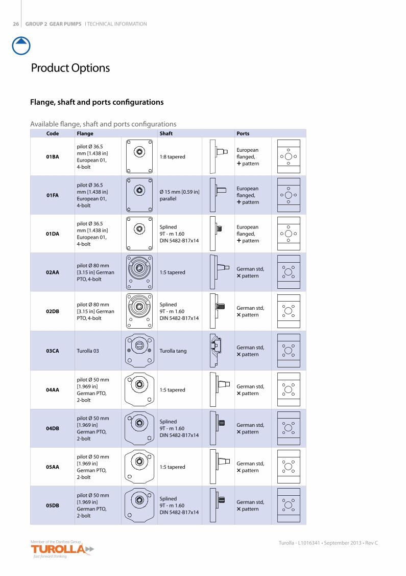
Flange, shaft and ports configurations
Available flange, shaft and ports configurationsCode Flange Shaft Ports
01BA
pilot Ø 36.5 mm [1.438 in]European 01, 4-bolt
1:8 taperedEuropean flanged, + pattern
01FA
pilot Ø 36.5 mm [1.438 in]European 01, 4-bolt
Ø 15 mm [0.59 in]parallel
European flanged, + pattern
01DA
pilot Ø 36.5 mm [1.438 in]European 01, 4-bolt
Splined9T - m 1.60DIN 5482-B17x14
European flanged, + pattern
02AApilot Ø 80 mm [3.15 in] German PTO, 4-bolt
1:5 taperedGerman std,× pattern
02DBpilot Ø 80 mm [3.15 in] German PTO, 4-bolt
Splined9T - m 1.60DIN 5482-B17x14
German std,× pattern
03CA Turolla 03 Turolla tangGerman std,× pattern
04AA
pilot Ø 50 mm [1.969 in] German PTO, 2-bolt
1:5 taperedGerman std,× pattern
04DB
pilot Ø 50 mm [1.969 in] German PTO, 2-bolt
Splined9T - m 1.60DIN 5482-B17x14
German std,× pattern
05AA
pilot Ø 50 mm [1.969 in] German PTO, 2-bolt
1:5 taperedGerman std,× pattern
05DB
pilot Ø 50 mm [1.969 in] German PTO, 2-bolt
Splined9T - m 1.60DIN 5482-B17x14
German std,× pattern

GROUP 2 GEAR PUMPS I TECHNICAL INFORMATION
77C33M
55K 50C100Y
66M88Y
66M88Y
27
Turolla - L1016341 • September 2013 • Rev C
Code Flange Shaft Port
06GApilot Ø 82.55 mm [3.25 in] SAE A, 2-bolt
Ø 15.875 mm [0.625 in]parallel
Threaded SAEO-Ring boss
06SApilot Ø 82.55 mm [3.25 in] SAE A, 2-bolt
9-teeth splined SAE spline J 498-9T-16/32DP
Threaded SAEO-Ring boss
06SBpilot Ø 82.55 mm [3.25 in] SAE A, 2-bolt
11-teeth splined SAE spline J 498-11T-16/32DP
Threaded SAEO-Ring boss
09BJ
pilot Ø 52.34 mm [2.061 in]Perkins 4.236 timing case
1:8 taperedGerman std× pattern
A9BJpilot Ø 52.34 mm [2.061 in] Perkins 900 series
1:8 taperedGerman std× pattern
GROUP 2 GEAR PUMPS I TECHNICAL INFORMATION28
Turolla - L1016341 • September 2013 • Rev C
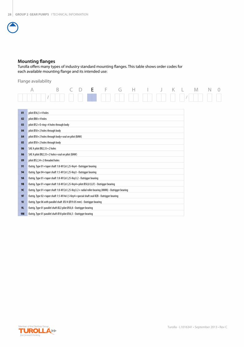
Mounting flangesTurolla offers many types of industry standard mounting flanges. This table shows order codes for each available mounting flange and its intended use:
Flange availability
01 pilot Ø36,5+4 holes
02 pilot Ø80+4 holes
03 pilot Ø52+O-ring+4 holes through body
04 pilot Ø50+2 holes through body
A4 pilot Ø50+2 holes through body+seal on pilot (BAW)
05 pilot Ø50+2 holes through body
06 SAE A pilot Ø82,55+2 holes
A6 SAE A pilot Ø82,55+2 holes+seal on pilot (BAW)
09 pilot Ø52,34+2 threaded holes
91 Outrig. Type 01+taper shaft 1:8-M12x1,25-Key4 - Outrigger bearing
94 Outrig. Type 04+taper shaft 1:5-M12x1,25-Key3 - Outrigger bearing
9A Outrig. Type 01+taper shaft 1:8-M12x1,25-Key3.2 - Outrigger bearing
9B Outrig. Type 01+taper shaft 1:8-M12x1,25-Key4+pilot Ø50,8 (LLF) - Outrigger bearing
9C Outrig. Type 01+taper shaft 1:8-M12x1,25-Key3.2+ radial roller bearing (MMN) - Outrigger bearing
9F Outrig. Type 02+taper shaft 1:5-M14x1,5-Key4+special shaft seal RZB - Outrigger bearing
9J Outrig. Type 06 with parallel shaft Ø3/4 (Ø19.05 mm) - Outrigger bearing
9L Outrig. Type 01 parallel shaft Ø22 pilot Ø50,8 - Outrigger bearing
9M Outrig. Type 01 parallel shaft Ø18 pilot Ø36,5 - Outrigger bearing
A B C D E F G H I J K L M N 0/ /
GROUP 2 GEAR PUMPS I TECHNICAL INFORMATION
77C33M
55K 50C100Y
66M88Y
66M88Y
29
Turolla - L1016341 • September 2013 • Rev C
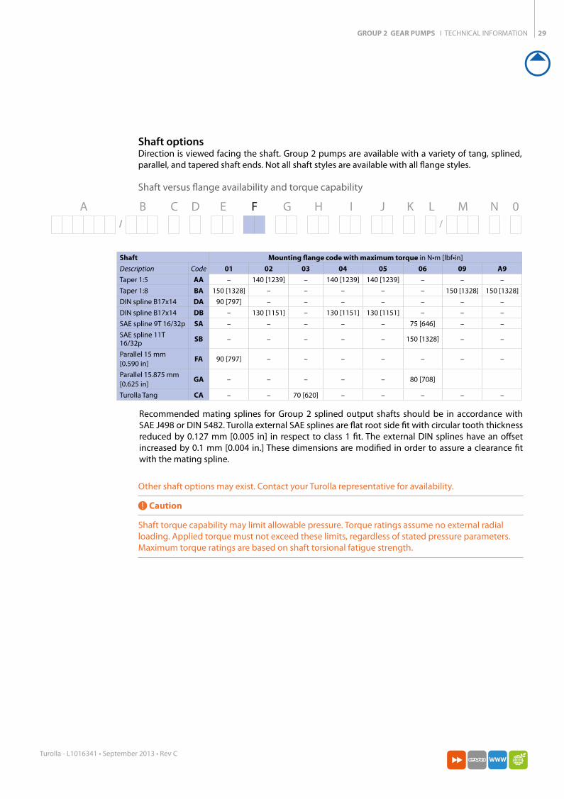
Shaft Mounting flange code with maximum torque in N•m [lbf•in]Description Code 01 02 03 04 05 06 09 A9Taper 1:5 AA – 140 [1239] – 140 [1239] 140 [1239] – – –Taper 1:8 BA 150 [1328] – – – – – 150 [1328] 150 [1328]DIN spline B17x14 DA 90 [797] – – – – – – –DIN spline B17x14 DB – 130 [1151] – 130 [1151] 130 [1151] – – –SAE spline 9T 16/32p SA – – – – – 75 [646] – –SAE spline 11T 16/32p SB – – – – – 150 [1328] – –
Parallel 15 mm [0.590 in]
FA 90 [797] – – – – – – –
Parallel 15.875 mm [0.625 in]
GA – – – – – 80 [708]
Turolla Tang CA – – 70 [620] – – – – –
Other shaft options may exist. Contact your Turolla representative for availability.
Caution
Shaft torque capability may limit allowable pressure. Torque ratings assume no external radial loading. Applied torque must not exceed these limits, regardless of stated pressure parameters. Maximum torque ratings are based on shaft torsional fatigue strength.
Recommended mating splines for Group 2 splined output shafts should be in accordance with SAE J498 or DIN 5482. Turolla external SAE splines are flat root side fit with circular tooth thickness reduced by 0.127 mm [0.005 in] in respect to class 1 fit. The external DIN splines have an offset increased by 0.1 mm [0.004 in.] These dimensions are modified in order to assure a clearance fit with the mating spline.
Shaft optionsDirection is viewed facing the shaft. Group 2 pumps are available with a variety of tang, splined, parallel, and tapered shaft ends. Not all shaft styles are available with all flange styles.
Shaft versus flange availability and torque capability
A B C D E F G H I J K L M N 0/ /
GROUP 2 GEAR PUMPS I TECHNICAL INFORMATION30
Turolla - L1016341 • September 2013 • Rev C
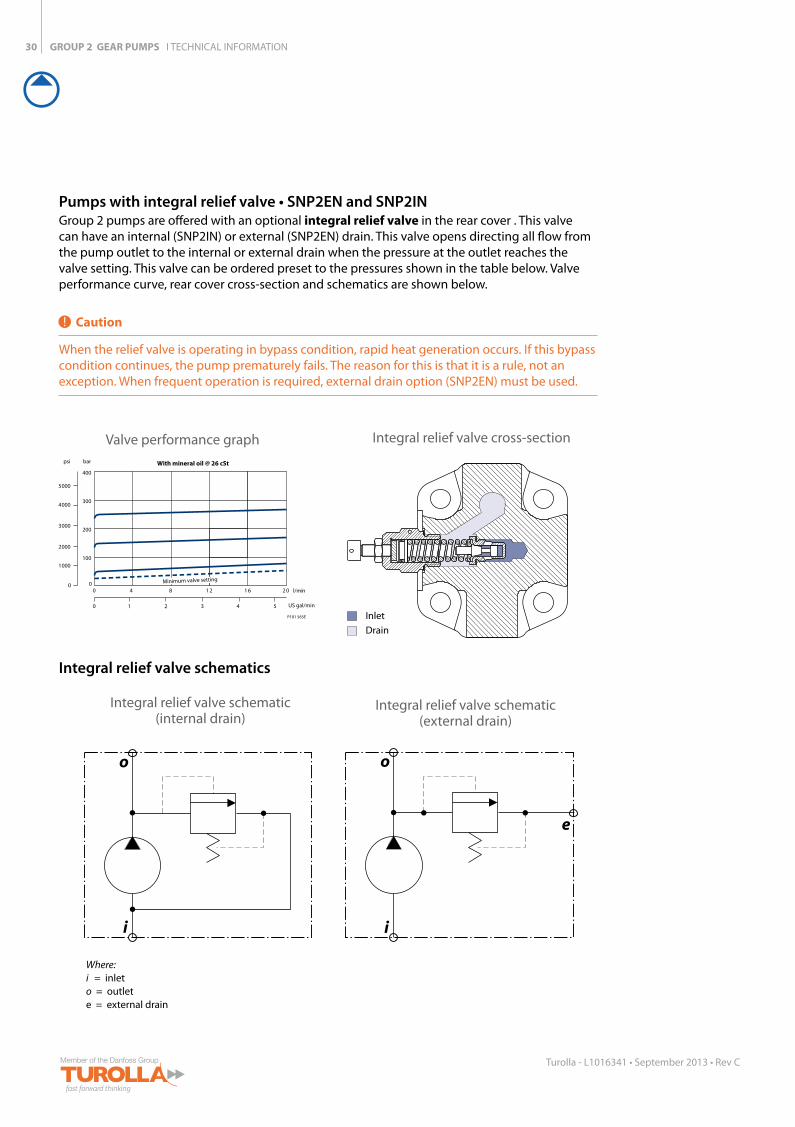
Pumps with integral relief valve • SNP2EN and SNP2INGroup 2 pumps are offered with an optional integral relief valve in the rear cover . This valve can have an internal (SNP2IN) or external (SNP2EN) drain. This valve opens directing all flow from the pump outlet to the internal or external drain when the pressure at the outlet reaches the valve setting. This valve can be ordered preset to the pressures shown in the table below. Valve performance curve, rear cover cross-section and schematics are shown below.
Caution
When the relief valve is operating in bypass condition, rapid heat generation occurs. If this bypass condition continues, the pump prematurely fails. The reason for this is that it is a rule, not an exception. When frequent operation is required, external drain option (SNP2EN) must be used.
Inlet
Drain
P101 016
Valve performance graphbar With mineral oil @ 26 cSt
0
1000
2000
3000
4000
5000
psi
0 4 8 1 2 1 6 2 0 l/min
0 1 2 3 4 5 US gal/min
0
100
200
300
400
P101 565E
Minimum valve setting
Where:i = inleto = outlete = external drain
Integral relief valve schematic (internal drain)
Integral relief valve cross-section
Integral relief valve schematic (external drain)
Integral relief valve schematics
GROUP 2 GEAR PUMPS I TECHNICAL INFORMATION
77C33M
55K 50C100Y
66M88Y
66M88Y
31
Turolla - L1016341 • September 2013 • Rev C
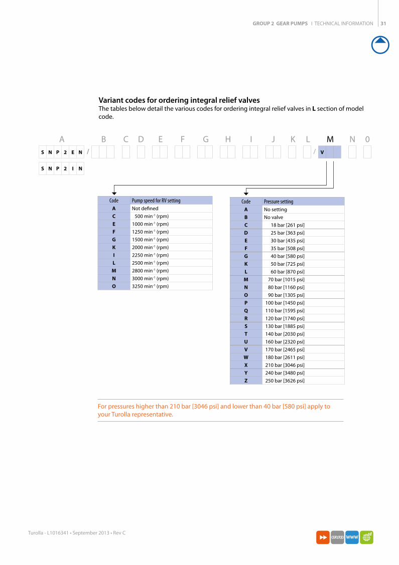
Variant codes for ordering integral relief valvesThe tables below detail the various codes for ordering integral relief valves in L section of model code.
Code Pressure settingA No settingB No valveC 18 bar [261 psi]D 25 bar [363 psi]E 30 bar [435 psi]F 35 bar [508 psi]G 40 bar [580 psi]K 50 bar [725 psi]L 60 bar [870 psi]M 70 bar [1015 psi]N 80 bar [1160 psi]O 90 bar [1305 psi]P 100 bar [1450 psi]Q 110 bar [1595 psi]R 120 bar [1740 psi]S 130 bar [1885 psi]T 140 bar [2030 psi]U 160 bar [2320 psi]V 170 bar [2465 psi]W 180 bar [2611 psi]X 210 bar [3046 psi]Y 240 bar [3480 psi]Z 250 bar [3626 psi]
Code Pump speed for RV settingA Not definedC 500 min-1 (rpm)E 1000 min-1 (rpm)F 1250 min-1 (rpm)G 1500 min-1 (rpm)K 2000 min-1 (rpm)I 2250 min-1 (rpm)L 2500 min-1 (rpm)M 2800 min-1 (rpm)N 3000 min-1 (rpm)O 3250 min-1 (rpm)
For pressures higher than 210 bar [3046 psi] and lower than 40 bar [580 psi] apply to your Turolla representative.
A B C D E F G H I J K L M N 0S N P 2 E N / / V
S N P 2 I N
GROUP 2 GEAR PUMPS I TECHNICAL INFORMATION32
Turolla - L1016341 • September 2013 • Rev C
mm [in]
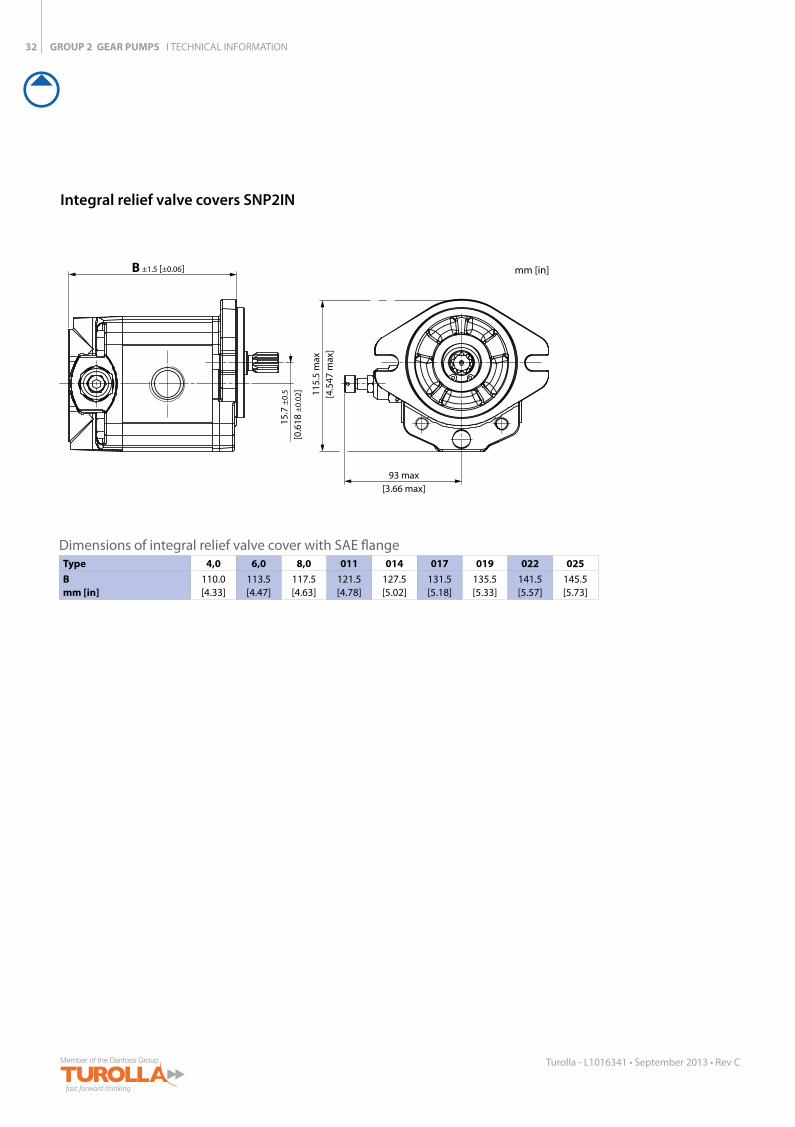
Integral relief valve covers SNP2IN
Dimensions of integral relief valve cover with SAE flangeType 4,0 6,0 8,0 011 014 017 019 022 025Bmm [in]
110.0 [4.33]
113.5 [4.47]
117.5 [4.63]
121.5 [4.78]
127.5 [5.02]
131.5 [5.18]
135.5 [5.33]
141.5 [5.57]
145.5 [5.73]
15.7
±0.
5
[0.6
18 ±
0.02
]
B ±1.5 [±0.06]
115.
5 m
ax[4
.547
max
]
93 max[3.66 max]
GROUP 2 GEAR PUMPS I TECHNICAL INFORMATION
77C33M
55K 50C100Y
66M88Y
66M88Y
33
Turolla - L1016341 • September 2013 • Rev C
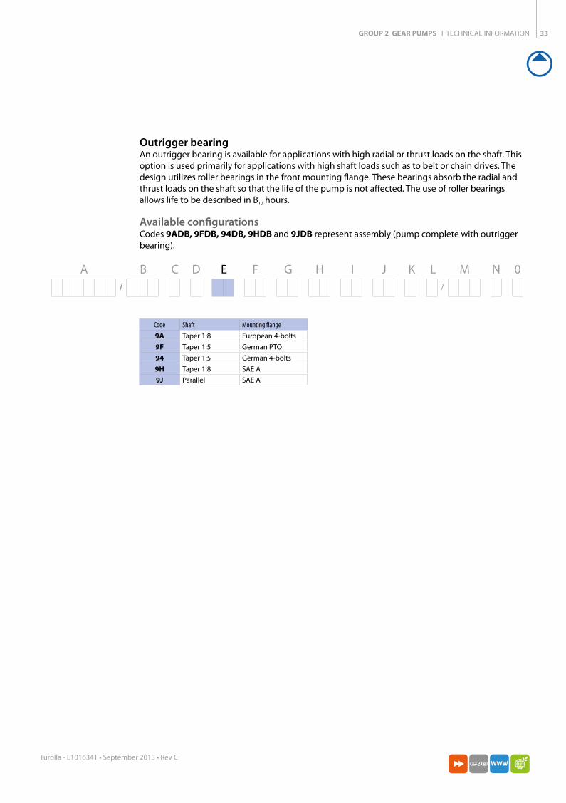
Outrigger bearingAn outrigger bearing is available for applications with high radial or thrust loads on the shaft. This option is used primarily for applications with high shaft loads such as to belt or chain drives. The design utilizes roller bearings in the front mounting flange. These bearings absorb the radial and thrust loads on the shaft so that the life of the pump is not affected. The use of roller bearings allows life to be described in B10 hours.
Available configurationsCodes 9ADB, 9FDB, 94DB, 9HDB and 9JDB represent assembly (pump complete with outrigger bearing).
Code Shaft Mounting flange9A Taper 1:8 European 4-bolts9F Taper 1:5 German PTO94 Taper 1:5 German 4-bolts9H Taper 1:8 SAE A9J Parallel SAE A
A B C D E F G H I J K L M N 0/ /
GROUP 2 GEAR PUMPS I TECHNICAL INFORMATION34
Turolla - L1016341 • September 2013 • Rev C
mm [in]
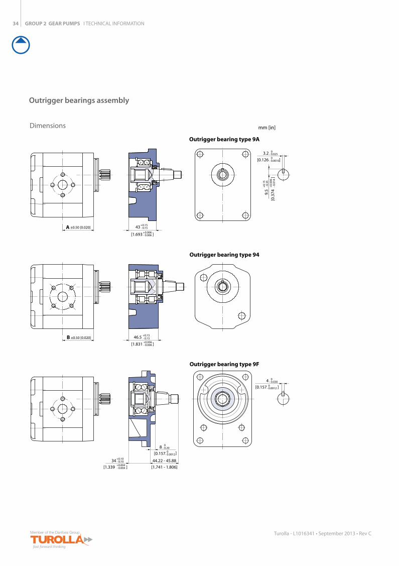
Outrigger bearings assembly
Dimensions
Outrigger bearing type 9A
Outrigger bearing type 94
43
]
- 0.15
+0.006- 0.006
+0.15
46.5
[1.831
3.2
[0.126 ]
- 0.0250
- 0.0010
0
9.5
[0.3
74]
- 0.3
5+
0.00
6- 0
.014
+0.
15
A ±0.50 [0.020]
B ±0.50 [0.020]
[1.693
]
- 0.15+0.006- 0.006
+0.15
Outrigger bearing type 9F
- 0.030 04
- 0.0012 0[0.157 ]
44.22 - 45.88
[1.741 - 1.806]
34
[1.339 ]- 0.10+0.004- 0.004
+0.10
- 0.20 08
- 0.0012 0[0.157 ]
GROUP 2 GEAR PUMPS I TECHNICAL INFORMATION
77C33M
55K 50C100Y
66M88Y
66M88Y
35
Turolla - L1016341 • September 2013 • Rev C
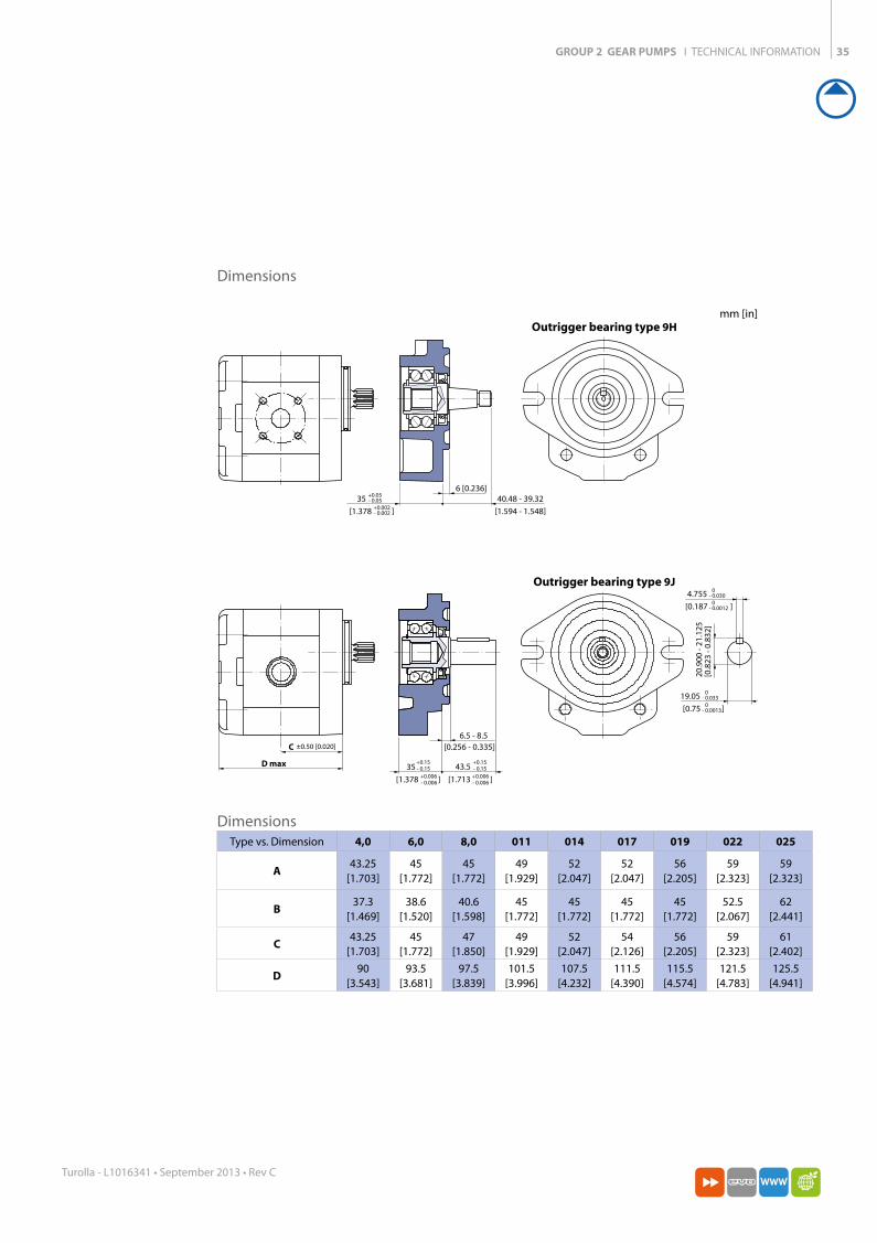
DimensionsType vs. Dimension 4,0 6,0 8,0 011 014 017 019 022 025
A43.25
[1.703]45
[1.772]45
[1.772]49
[1.929]52
[2.047]52
[2.047]56
[2.205]59
[2.323]59
[2.323]
B37.3
[1.469]38.6
[1.520]40.6
[1.598]45
[1.772]45
[1.772]45
[1.772]45
[1.772]52.5
[2.067]62
[2.441]
C43.25
[1.703]45
[1.772]47
[1.850]49
[1.929]52
[2.047]54
[2.126]56
[2.205]59
[2.323]61
[2.402]
D90
[3.543]93.5
[3.681]97.5
[3.839]101.5
[3.996]107.5
[4.232]111.5
[4.390]115.5
[4.574]121.5
[4.783]125.5
[4.941]
Outrigger bearing type 9J
6.5 - 8.5[0.256 - 0.335]
35
[1.378 ]- 0.15
+0.006- 0.006
+0.1543.5
[1.713 ]- 0.15+0.006- 0.006
+0.15
20.9
00 -
21.1
25[0
.823
- 0.
832]
4.755
[0.187 ]- 0.030
0- 0.0012
0
19.05
[0.75 ]- 0.033
- 0.0013
0
C ±0.50 [0.020]
D max
0
6 [0.236]
Outrigger bearing type 9H
35
[1.378 ]- 0.05
+0.002- 0.002
+0.05 40.48 - 39.32
[1.594 - 1.548]
Dimensions
mm [in]
GROUP 2 GEAR PUMPS I TECHNICAL INFORMATION36
Turolla - L1016341 • September 2013 • Rev C
SAE A Pad
SAE J498-9T-16/32DP-flat root side fit
A 17x14 DIN 5482
o-ring
M10-6H thru
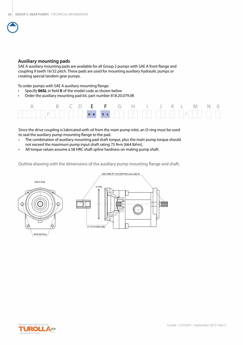
Auxiliary mounting padsSAE A auxiliary mounting pads are available for all Group 2 pumps with SAE A front flange and coupling 9 teeth 16/32 pitch. These pads are used for mounting auxiliary hydraulic pumps or creating special tandem gear pumps.
To order pumps with SAE A auxiliary mounting flange: • Specify 06SL in field E of the model code as shown below • Order the auxiliary mounting pad kit, part number 818.20.079.0K
A B C D E F G H I J K L M N 0/ 0 6 S L /
Since the drive coupling is lubricated with oil from the main pump inlet, an O-ring must be used to seal the auxiliary pump-mounting flange to the pad. • The combination of auxiliary mounting pad shaft torque, plus the main pump torque should
not exceed the maximum pump input shaft rating 75 N•m [664 lbf•in]. • All torque values assume a 58 HRC shaft spline hardness on mating pump shaft.
Outline drawing with the dimensions of the auxiliary pump mounting flange and shaft.
GROUP 2 GEAR PUMPS I TECHNICAL INFORMATION
77C33M
55K 50C100Y
66M88Y
66M88Y
37
Turolla - L1016341 • September 2013 • Rev C
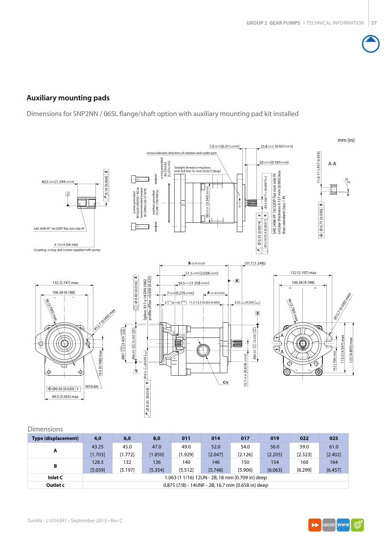
Auxiliary mounting pads
Dimensions for SNP2NN / 06SL flange/shaft option with auxiliary mounting pad kit installed
o-r
ing
pro
vid
ed82
.22x
2.62
[3.2
37x.
103]
X K
X
YM10-6H
Z
X
C/c
=
A
A
=
122
[4.8
03] m
ax
115.
5 [4
.547
] max
19.5
[.76
8] m
ax
106.38 [4.188]
106.38 [4.188]
132 [5.197] max
132 [5.197] max
(R12
.7 [0
.500
] max
)
96 [3.780] max
96 [3.780] max
Ø0.50 [0.020]
= =
90.5 [3.563] max
19.5
[0.7
68] m
ax
R12.7 [0.500] m
ax
(min full thd 16.7mm [0.657] deep)
Ø 0
.35
[0.0
014]
Ø 0
.10/
25.4
[0.0
04/1
]
SAE
J498
-9T-
16/3
2DP-
flat
roo
t si
de
fitci
rcu
lar t
hic
knes
s 0.
127
mm
[0.0
05] l
ess
than
sta
nd
ard
cla
ss 1
fit
Straight thread o-ring boss
A 17x14 DIN 5482
Coupling, o-ring, and screws supplied with pump
Z 0.10
[0.0
04]
A-A
Ø 0
.75
[0.0
30]
11.6
-11
[.457
-0.4
33]
0-3°
arrow indicates direction of rotation and outlet port
SAE J498-9T-16/32DP-flat root side fit
Ø 0
.35
[0.0
14]
Splin
e: B
17 x
14
DIN
548
2p
rofil
e o
ffse
t +
0.60
0 [0
.025
]
K
X
Ø 0
.40
[0.0
16]
Y
Y
B ±0.50 [0.020]
A ±0.50 [0.020]
(31.7 [1.248])
11.5-12.5 [0.453-0.492]
40.5 ±0.25 ±0.010[1.594 ]
7±0.20 ±0.008[0.276 ]
34.5±1.2 ±0.047[1.358 ]
51.5±0.90 ±0.035[2.028 ]
15.7
±0.
50±
0.03
5[0
.618
]
23.8 ±0.25 ±0.010[0.937 ]7.9 ±0.75 ±0.030[0.311 ]
20 ±0.75 ±0.030[0.787 ]
Ø15
.456
+0
+0
-0.0
05-0
.127
[0.6
09]
3 +0.006+0.1500 [0.118 ] 6.35 00
-0.020-0.50 [0.250 ]
Ø16
.50
0-0
.004
-0.1
10[0
.650
]
Ø82
.55
+0.
003
+0.
077
-0.0
01-0
.023
[3.2
50]
Ø82
.55
+0.
003
+0.
077
-0.0
01-0
.023
[3.2
50]
Ø87
+0.
002
+0.
05-0
.006
-0.1
5[3
.425
]
scre
ws
pro
vid
edM
10x3
0 U
NI5
931
8G b
rre
com
men
ded
to
rqu
e:40
-50N
m [3
0-37
lb•f
t]
was
her
s p
rovi
ded
10 U
NI 1
750
R40
br
90±
0.25
±0.
010
[3.5
43]
DimensionsType (displacement) 4,0 6,0 8,0 011 014 017 019 022 025
A43.25
[1.703]
45.0
[1.772]
47.0
[1.850]
49.0
[1.929]
52.0
[2.047]
54.0
[2.126]
56.0
[2.205]
59.0
[2.323]
61.0
[2.402]
B128.5
[5.059]
132
[5.197]
136
[5.354]
140
[5.512]
146
[5.748]
150
[5.906]
154
[6.063]
160
[6.299]
164
[6.457]
Inlet C 1.063 (1 1/16) 12UN - 2B; 18 mm [0.709 in] deep
Outlet c 0.875 (7/8) - 14UNF - 2B; 16.7 mm [0.658 in] deep
mm [in]

GROUP 2 GEAR PUMPS I TECHNICAL INFORMATION38
Turolla - L1016341 • September 2013 • Rev C
Pump ports
Dimensions of pumps ports
Port type B Style C Style E Style F Style
Port dimensions a b c d g h e f
Fram
e si
ze
4,0Inlet 15 [0.591] 40 [1.575] M6 13.5 [0.531] 30 [1.181] M6 1 1/ 16–12UNF–2B ½ Gas (BSPP)Outlet 15 [0.591] 35 [1.378] M6 13.5 [0.531] 30 [1.181] M6 7/ 8–14UNF–2B ½ Gas (BSPP)
6,0Inlet 15 [0.591] 40 [1.575] M6 13.5 [0.531] 30 [1.181] M6 1 1/ 16–12UNF–2B ½ Gas (BSPP)Outlet 15 [0.591] 35 [1.378] M6 13.5 [0.531] 30 [1.181] M6 7/ 8–14UNF–2B ½ Gas (BSPP)
8,0Inlet 20 [0.787] 40 [1.575] M6 13.5 [0.531] 30 [1.181] M6 1 1/ 16–12UNF–2B ½ Gas (BSPP)Outlet 15 [0.591] 35 [1.378] M6 13.5 [0.531] 30 [1.181] M6 7/ 8–14UNF–2B ½ Gas (BSPP)
011Inlet 20 [0.787] 40 [1.575] M6 13.5 [0.531] 30 [1.181] M6 1 1/ 16–12UNF–2B ¾ Gas (BSPP)Outlet 15 [0.591] 35 [1.378] M6 13.5 [0.531] 30 [1.181] M6 7/ 8–14UNF–2B ½ Gas (BSPP)
014Inlet 20 [0.787] 40 [1.575] M6 20.0 [0.787] 40 [1.575] M8 1 1/ 16–12UNF–2B ¾ Gas (BSPP)Outlet 15 [0.591] 35 [1.378] M6 13.5 [0.531] 30 [1.181] M6 7/ 8–14UNF–2B ½ Gas (BSPP)
017Inlet 20 [0.787] 40 [1.575] M6 20.0 [0.787] 40 [1.575] M8 1 1/ 16–12UNF–2B ¾ Gas (BSPP)Outlet 15 [0.591] 35 [1.378] M6 13.5 [0.531] 30 [1.181] M6 7/ 8–14UNF–2B ½ Gas (BSPP)
019Inlet 20 [0.787] 40 [1.575] M6 20.0 [0.787] 40 [1.575] M8 1 1/ 16–12UNF–2B ¾ Gas (BSPP)Outlet 15 [0.591] 35 [1.378] M6 13.5 [0.531] 30 [1.181] M6 7/ 8–14UNF–2B ½ Gas (BSPP)
022Inlet 20 [0.787] 40 [1.575] M6 20.0 [0.787] 40 [1.575] M8 1 1/ 16–12UNF–2B ¾ Gas (BSPP)Outlet 15 [0.591] 35 [1.378] M6 13.5 [0.531] 30 [1.181] M6 7/ 8–14UNF–2B ½ Gas (BSPP)
025Inlet 20 [0.787] 40 [1.575] M6 23.5 [0.925] 40 [1.575] M8 1 1/ 16–12UNF–2B 1 Gas (BSPP)Outlet 15 [0.591] 35 [1.378] M6 20.0 [0.787] 40 [1.575] M8 7/ 8–14UNF–2B ¾ Gas (BSPP)
b
B C FE
ca
(4 holes min. full thd.10 [0.394] deep)
fhg
45o
(4 holes min. full thd.10 [0.394] deep)
ed
Available pump ports
GROUP 2 GEAR PUMPS I TECHNICAL INFORMATION
77C33M
55K 50C100Y
66M88Y
66M88Y
39
Turolla - L1016341 • September 2013 • Rev C
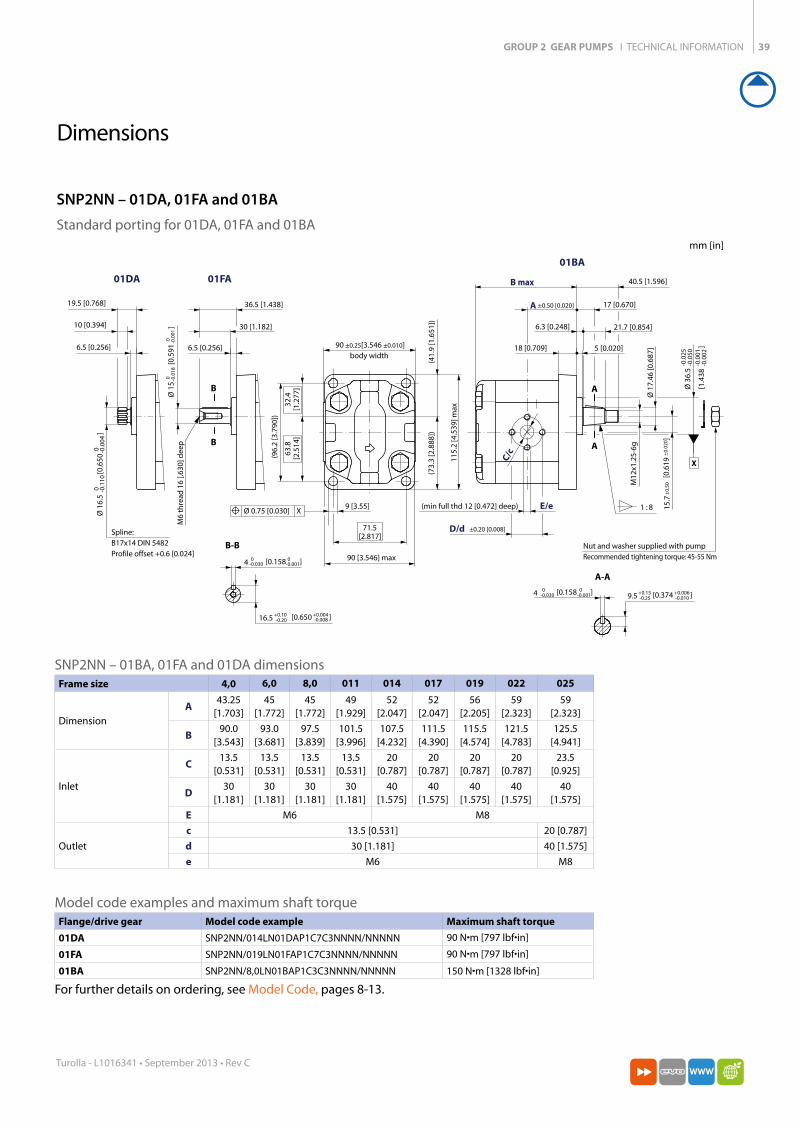
Dimensions
SNP2NN – 01BA, 01FA and 01DA dimensionsFrame size 4,0 6,0 8,0 011 014 017 019 022 025
Dimension
A43.25
[1.703]45
[1.772]45
[1.772]49
[1.929]52
[2.047]52
[2.047]56
[2.205]59
[2.323]59
[2.323]
B90.0
[3.543]93.0
[3.681]97.5
[3.839]101.5
[3.996]107.5
[4.232]111.5
[4.390]115.5
[4.574]121.5
[4.783]125.5
[4.941]
Inlet
C13.5
[0.531]13.5
[0.531]13.5
[0.531]13.5
[0.531]20
[0.787]20
[0.787]20
[0.787]20
[0.787]23.5
[0.925]
D30
[1.181]30
[1.181]30
[1.181]30
[1.181]40
[1.575]40
[1.575]40
[1.575]40
[1.575]40
[1.575]E M6 M8
Outlet
c 13.5 [0.531] 20 [0.787]d 30 [1.181] 40 [1.575]e M6 M8
Model code examples and maximum shaft torque Flange/drive gear Model code example Maximum shaft torque
01DA SNP2NN/014LN01DAP1C7C3NNNN/NNNNN 90 N•m [797 lbf•in]
01FA SNP2NN/019LN01FAP1C7C3NNNN/NNNNN 90 N•m [797 lbf•in]
01BA SNP2NN/8,0LN01BAP1C3C3NNNN/NNNNN 150 N•m [1328 lbf•in]
For further details on ordering, see Model Code, pages 8-13.
Standard porting for 01DA, 01FA and 01BA
[0.374 ]+0.15 +0.006-0.25 -0.010
[1.4
38
]
-0.0
25-0
.050
-0.0
01-0
.002
9 [3.55]
Nut and washer supplied with pumpRecommended tightening torque: 45-55 Nm
[0.6
19
]
A
A
(min full thd 12 [0.472] deep) 1 : 8
A-A
M12
x1.2
5-6g
E/e
40.5 [1.596]
6.3 [0.248] 21.7 [0.854]
17 [0.670]
18 [0.709] 5 [0.020]
C/c
M6
thre
ad 1
6 [.6
30] d
eep
B-B
B
B
6.5 [0.256]
30 [1.182]
36.5 [1.438]
Spline:B17x14 DIN 5482Profile offset +0.6 [0.024]
6.5 [0.256]
10 [0.394]
19.5 [0.768]
body width
(96.
2 [3
.790
])
115.
2 [4
.539
] max
90 [3.546] max
D/d ±0.20 [0.008]
(41.
9 [1
.651
])
71.5[2.817]
63.8
[2.5
14]
32.4
[1.2
77]
(73.
3 [2
.888
])
90 ±0.25[3.546 ±0.010]
15.7
±0.
50±
0.02
0
4 0 0-0.030 [0.158 ]-0.001 9.5
Ø 1
6.5
[
0.65
0
]0 -0
.110
0 -0.0
04
Ø 3
6.5
Ø 1
7.46
[0.6
87]
Ø 1
5
[0.5
91
]0 -0
.018
0 -0.0
01
X
Ø 0.75 [0.030] X
01BA
±0.50 [0.020]
B max
A
01FA01DA
[0.650 ]16.5 +0.10-0.20
+0.004-0.008
4 0-0.030
0-0.001[0.158 ]
SNP2NN – 01DA, 01FA and 01BA
mm [in]
GROUP 2 GEAR PUMPS I TECHNICAL INFORMATION40
Turolla - L1016341 • September 2013 • Rev C
3 [0.118 ]
Ø 8
0
[3.1
50
]
9 [0.354]
Ø 1
6.5
[
0.65
0
]
Spline:B17x14 DIN 5482profile offset +0.6 [.024]
13.5 [0.531]
23.5 [0.952]
1 : 5
A
A-A
A
M12
x1.2
5-6g
16.5 [0.650]
E/e
C/c
17.4
6[0
.687
]
38 [1.496]B max
12.5 [0.492] 7.2 [0.283]
5.7 [0.224] 19.3 [0.760]
45°body width
(100
[3.9
37])
D/d ±0.20 [±0.008]
A
72[2.835]
120
[4.7
24] m
ax
92 [3.622] max
(44.
5 [1
.72]
)
65.5
[2.5
79]
34.5
[1.3
58]
(75.
5 [2
.972
])
90 ±0.25 [3.543 ±0.010]
0 -0.1
100 -0
.004
-0.0
60-0
.090
-0.0
02-0
.003
0-0.025
0-0.001 9 [0.354 ]+0.30
-0.10+0.012-0.004
15.7
[
0.61
8
]±
0.50
±0.
02
Ø 0.75 [0.030] X
X
(min full thd 12 [0.472] deep)
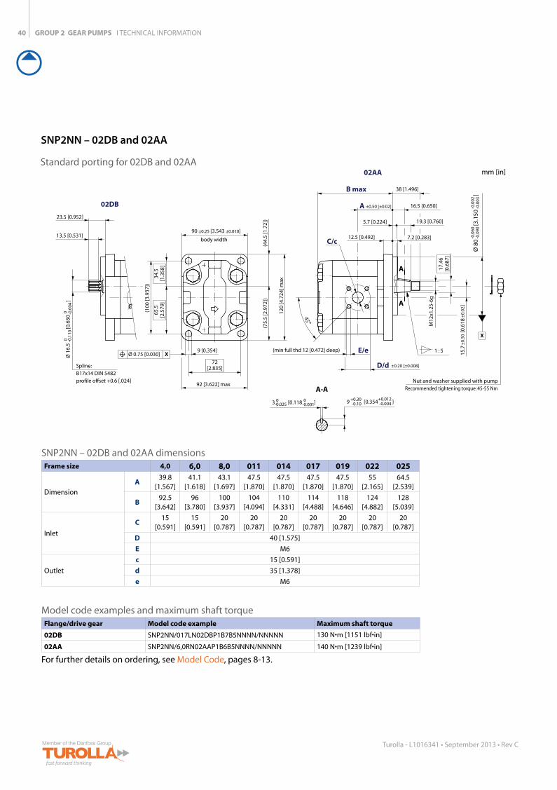
02DB
02AA
±0.50 [±0.02]
Nut and washer supplied with pumpRecommended tightening torque: 45-55 Nm
SNP2NN – 02DB and 02AA dimensionsFrame size 4,0 6,0 8,0 011 014 017 019 022 025
Dimension
A39.8
[1.567]41.1
[1.618]43.1
[1.697]47.5
[1.870]47.5
[1.870]47.5
[1.870]47.5
[1.870]55
[2.165]64.5
[2.539]
B92.5
[3.642]96
[3.780]100
[3.937]104
[4.094]110
[4.331]114
[4.488]118
[4.646]124
[4.882]128
[5.039]
Inlet
C15
[0.591]15
[0.591]20
[0.787]20
[0.787]20
[0.787]20
[0.787]20
[0.787]20
[0.787]20
[0.787]D 40 [1.575]E M6
Outlet
c 15 [0.591]d 35 [1.378]e M6
Model code examples and maximum shaft torque Flange/drive gear Model code example Maximum shaft torque
02DB SNP2NN/017LN02DBP1B7B5NNNN/NNNNN 130 N•m [1151 lbf•in]
02AA SNP2NN/6,0RN02AAP1B6B5NNNN/NNNNN 140 N•m [1239 lbf•in]
For further details on ordering, see Model Code, pages 8-13.
Standard porting for 02DB and 02AA
SNP2NN – 02DB and 02AA
mm [in]
GROUP 2 GEAR PUMPS I TECHNICAL INFORMATION
77C33M
55K 50C100Y
66M88Y
66M88Y
41
Turolla - L1016341 • September 2013 • Rev C
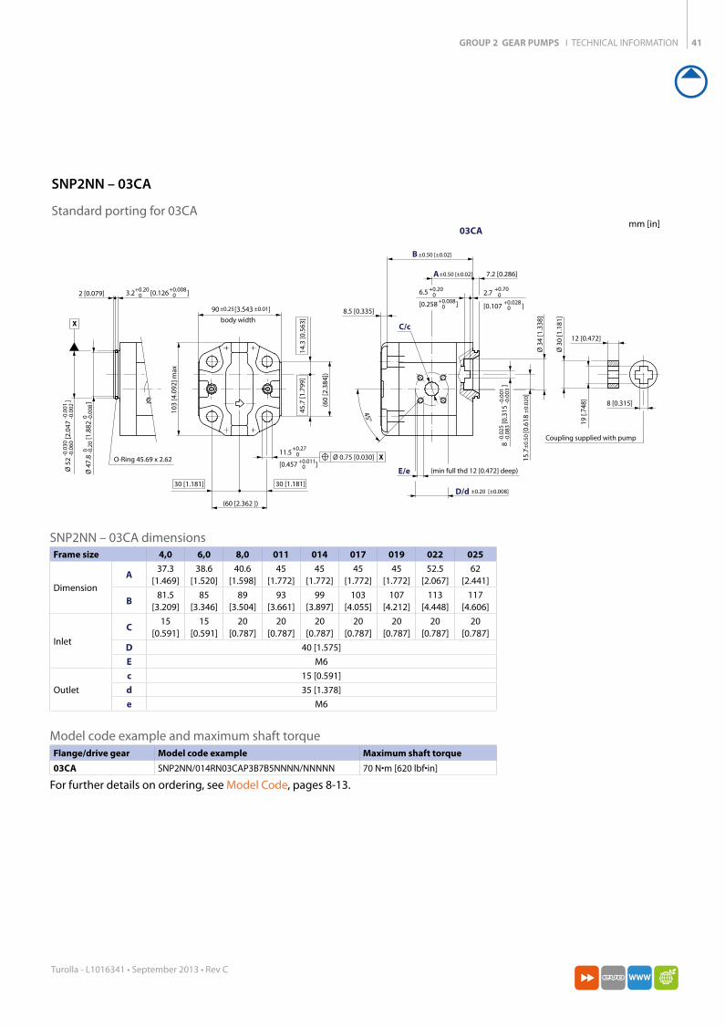
3.2 [0.126 ]+0.200
+0.00802 [0.079]
(min full thd 12 [0.472] deep)
Ø 3
4 [1
.338
]
7.2 [0.286]
19
[.748
]
Ø 3
0 [1
.181
]
12 [0.472]
45°
X
O-Ring 45.69 x 2.62
body width(6
0 [2
.384
])
B ±0.50 [±0.02]
A
(60 [2.362 ])
103
[4.0
92] m
ax
Ø 5
2
[2.
047
]
-0.0
30-0
.060
-0.0
01-0
.002
8
[0.
315
]
-0.0
25-0
.083
-0.0
01-0
.003
11.5
[0.457 ]
+0.270+0.011
0
2.7
[0.107 ]
+0.700
+0.0280
6.5
[0.258 ]
+0.200
+0.0080
Ø 4
7.8
[1
.882
]
0 -0.2
00 -0
.008
15.7
[0
.618
]±
0.50
±0.
020
90 [3.543 ]±0.25 ±0.01
Ø 0.75 [0.030] X
8 [0.315]
Coupling supplied with pump
±0.50 [±0.02]
D/d
E/e
C/c
±0.20 [±0.008]
03CA
45.7
[1.7
99]
14.3
[0.5
63]
30 [1.181]30 [1.181]
8.5 [0.335]
SNP2NN – 03CA dimensionsFrame size 4,0 6,0 8,0 011 014 017 019 022 025
Dimension
A37.3
[1.469]38.6
[1.520]40.6
[1.598]45
[1.772]45
[1.772]45
[1.772]45
[1.772]52.5
[2.067]62
[2.441]
B81.5
[3.209]85
[3.346]89
[3.504]93
[3.661]99
[3.897]103
[4.055]107
[4.212]113
[4.448]117
[4.606]
Inlet
C15
[0.591]15
[0.591]20
[0.787]20
[0.787]20
[0.787]20
[0.787]20
[0.787]20
[0.787]20
[0.787]D 40 [1.575]E M6
Outlet
c 15 [0.591]d 35 [1.378]e M6
Model code example and maximum shaft torque Flange/drive gear Model code example Maximum shaft torque
03CA SNP2NN/014RN03CAP3B7B5NNNN/NNNNN 70 N•m [620 lbf•in]
For further details on ordering, see Model Code, pages 8-13.
SNP2NN – 03CA
Standard porting for 03CAmm [in]
GROUP 2 GEAR PUMPS I TECHNICAL INFORMATION42
Turolla - L1016341 • September 2013 • Rev C
3
[0.118 ]
11.5
[0.453 ]
Ø 1
6.5
[0.6
5
]
A ±0.50 [±0.02]
B
8.5 [0.335]
±0.50 [0.02]
+0.27 0+0.011
0
Spline:
B17x14 DIN 5482
profile offset +0.6 [0.024]
13.5 [0.531]
26 [1.024]
A-A
A
A
1 : 5
X
(min full thd 12
[0.472] deep)
M12
x1.2
5-6g
17.4
6 [0
.687
]
19 [0.748]
E/e
C/c 7.2 [0.283]
40.5 [1.594]
8.2 [0.323] 19.3 [0.760]
45°
body width
(60
[2.3
62])
D/d ±0.20 [±0.008]
90 ±0.50 [3.543 ±0.010]
(60 [2.362])
103
[4.0
55] m
ax
45.7
[1.7
99]
14.3
[0.5
63]
30 [1.181]
Ø0.75 [0.030] X
0 -0.1
100 -0
.004
-0.0
25-0
.064
Ø 5
0
[1
.969
]
-0.0
01-0
.002
5
+0.
30-0
.10
9 [0.3
54
]
+0.
012
-0.0
04
0-0.025
0-0.001
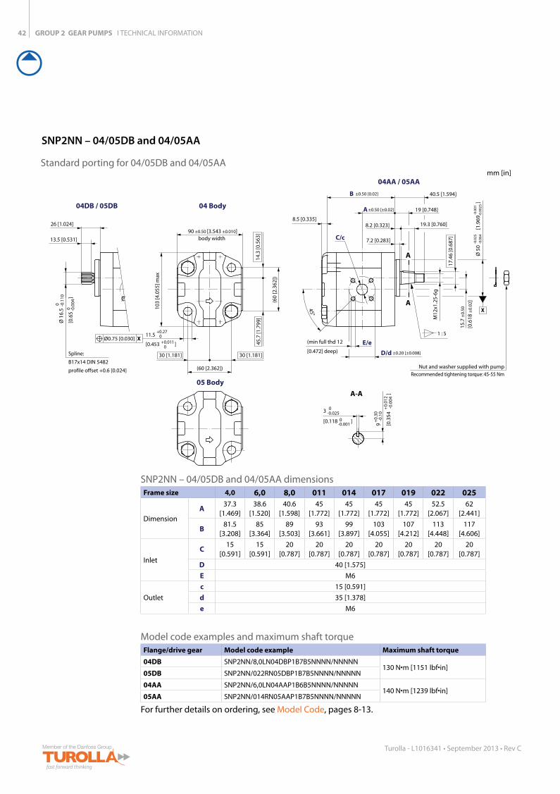
04DB / 05DB 04 Body
05 Body
04AA / 05AA
15.7
±0.
50
[0.6
18 ±
0.02
]
30 [1.181]
Nut and washer supplied with pumpRecommended tightening torque: 45-55 Nm
SNP2NN – 04/05DB and 04/05AA dimensionsFrame size 4,0 6,0 8,0 011 014 017 019 022 025
Dimension
A37.3
[1.469]38.6
[1.520]40.6
[1.598]45
[1.772]45
[1.772]45
[1.772]45
[1.772]52.5
[2.067]62
[2.441]
B81.5
[3.208]85
[3.364]89
[3.503]93
[3.661]99
[3.897]103
[4.055]107
[4.212]113
[4.448]117
[4.606]
Inlet
C15
[0.591]15
[0.591]20
[0.787]20
[0.787]20
[0.787]20
[0.787]20
[0.787]20
[0.787]20
[0.787]D 40 [1.575]E M6
Outlet
c 15 [0.591]d 35 [1.378]e M6
Model code examples and maximum shaft torque Flange/drive gear Model code example Maximum shaft torque
04DB SNP2NN/8,0LN04DBP1B7B5NNNN/NNNNN130 N•m [1151 lbf•in]
05DB SNP2NN/022RN05DBP1B7B5NNNN/NNNNN
04AA SNP2NN/6,0LN04AAP1B6B5NNNN/NNNNN140 N•m [1239 lbf•in]
05AA SNP2NN/014RN05AAP1B7B5NNNN/NNNNN
For further details on ordering, see Model Code, pages 8-13.
SNP2NN – 04/05DB and 04/05AA
Standard porting for 04/05DB and 04/05AAmm [in]
GROUP 2 GEAR PUMPS I TECHNICAL INFORMATION
77C33M
55K 50C100Y
66M88Y
66M88Y
43
Turolla - L1016341 • September 2013 • Rev C
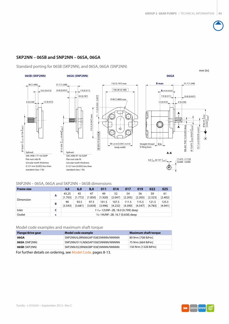
SNP2NN – 06SA, 06GA and SKP2NN – 06SB dimensionsFrame size 4,0 6,0 8,0 011 014 017 019 022 025
Dimension
A43.25
[1.703]45
[1.772]47
[1.850]49
[1.920]52
[2.047]54
[2.205]56
[2.205]59
[2.323]61
[2.402]
B90
[3.543]93.5
[3.681]97.5
[3.839]101.5
[3.996]107.5
[4.232]111.5
[4.390]115.5
[4.547]121.5
[4.783]125.5
[4.941]Inlet C 11/ 16–12UNF–2B, 18.0 [0.709] deepOutlet c 7/ 8–14UNF–2B, 16.7 [0.658] deep
Model code examples and maximum shaft torque Flange/drive gear Model code example Maximum shaft torque
06GA SNP2NN/6,0RN06GAP1E6E5NNNN/NNNNN 80 N•m [708 lbf•in]
06SA (SNP2NN) SNP2NN/011LN06SAP1E6E5NNNN/NNNNN 75 N•m [664 lbf•in]
06SB (SKP2NN) SKP2NN/022RN06SBP1E6E5NNNN/NNNNN 150 N•m [1328 lbf•in]
For further details on ordering, see Model Code, pages 8-13.
A
A
A-A
7.9 [0.311] 23.8 [0.937]
B max 31.7 [1.248]
C/c
M6-
6H- T
HD
16
[0.6
30] d
eep
17.475 -17.729[0.688 - 0.698]
12 [0.472] 6 [0.236]
body width
11 -
11.6
[0.4
33 -
0.45
7]
A ±0.50 [0.020]
132 [5.197] max
106.38 [4.188]11
5.5
[4.5
47] m
ax
Ø 8
2.55
[3.2
50
]
0 -0.0
500 -0
.020
4.0 [0.157 ]0-0.03
0-0.001
Ø 1
5.87
5
[0.
625
]
0 -0.0
250 -0
.010
15.7
±0.
50 [0
.618
±0.
020
]
Ø 0
.75
[0.0
30] X
X
Straight thread O-Ring boss
06SA (SNP2NN)
12 [0.472]6 [0.236]
Splined:
SAE J498-11T-16/32DP
Flat root side fit
(circular tooth thickness
0.127 mm [0.005] less than
standard class 1 fit)
38 [1.496]
10.5 [0.413]
Ø 1
8.63
1
[0.
734
]
0 -0.1
270 -0
.005
06SB (SKP2NN) 06GA
20 [0.787]
31.7 [1.248]
23.8 [0.937] 7.9 [0.311]
Ø 1
5.45
6
[0.
609
]
0 -0.1
270 -0
.005
90 ±0.50 [3.543 ±0.010]
R 48 [1.889] max
Splined:
SAE J498-9T-16/32DP
Flat root side fit
(circular tooth thickness
0.127 mm [0.005] less than
standard class 1 fit)
SKP2NN – 06SB and SNP2NN – 06SA, 06GA
Standard porting for 06SB (SKP2NN), and 06SA, 06GA (SNP2NN) mm [in]
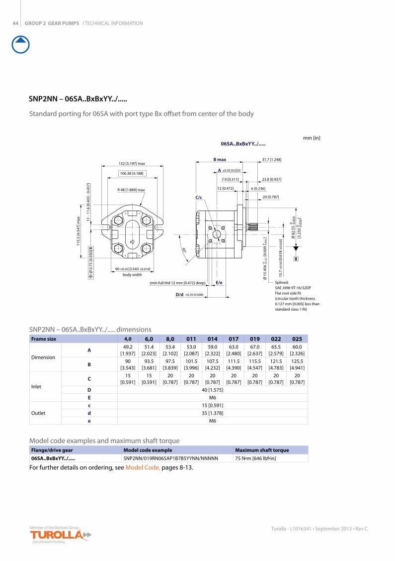
GROUP 2 GEAR PUMPS I TECHNICAL INFORMATION44
Turolla - L1016341 • September 2013 • Rev C
SNP2NN – 06SA..BxBxYY../..... dimensionsFrame size 4,0 6,0 8,0 011 014 017 019 022 025
Dimension
A49.2
[1.937]51.4
[2.023]53.4
[2.102]53.0
[2.087]59.0
[2.322]63.0
[2.480]67.0
[2.637]65.5
[2.579]60.0
[2.326]
B90
[3.543]93.5
[3.681]97.5
[3.839]101.5
[3.996]107.5
[4.232]111.5
[4.390]115.5
[4.547]121.5
[4.783]125.5
[4.941]
Inlet
C15
[0.591]15
[0.591]20
[0.787]20
[0.787]20
[0.787]20
[0.787]20
[0.787]20
[0.787]20
[0.787]D 40 [1.575]E M6
Outlet
c 15 [0.591]d 35 [1.378]e M6
Model code examples and maximum shaft torque Flange/drive gear Model code example Maximum shaft torque
06SA..BxBxYY../..... SNP2NN/019RN06SAP1B7B5YYNN/NNNNN 75 N•m [646 lbf•in]
For further details on ordering, see Model Code, pages 8-13.
X
20 [0.787]
45°
E/e
C/c
B max
D/d
A
06SA..BxBxYY../.....
7.9 [0.311] 23.8 [0.937]
31.7 [1.248]
12 [0.472] 6 [0.236]
11 -
11.6
[0.4
33 -
0.45
7]
±0.50 [0.020]
132 [5.197] max
106.38 [4.188]
115.
5 [4
.547
] max
Ø 8
2.55
[3.2
50
]
0 -0.0
50
0 -0.0
20
Ø 0
.75
[0.0
30] X
Splined: SAE J498-9T-16/32DP Flat root side fit (circular tooth thickness 0.127 mm [0.005] less than standard class 1 fit)
body width
90 ±0.50 [3.543 ±0.010]
(min full thd 12 mm [0.472] deep)
±0.20 [0.008]
R 48 [1.889] max
Ø 1
5.45
6
[0.6
09
] 0 -0
.127
0 -0
.005
15.7
±0.
50 [0
.618
±0.
020]
Standard porting for 06SA with port type Bx offset from center of the body
SNP2NN – 06SA..BxBxYY../.....
mm [in]
GROUP 2 GEAR PUMPS I TECHNICAL INFORMATION
77C33M
55K 50C100Y
66M88Y
66M88Y
45
Turolla - L1016341 • September 2013 • Rev C
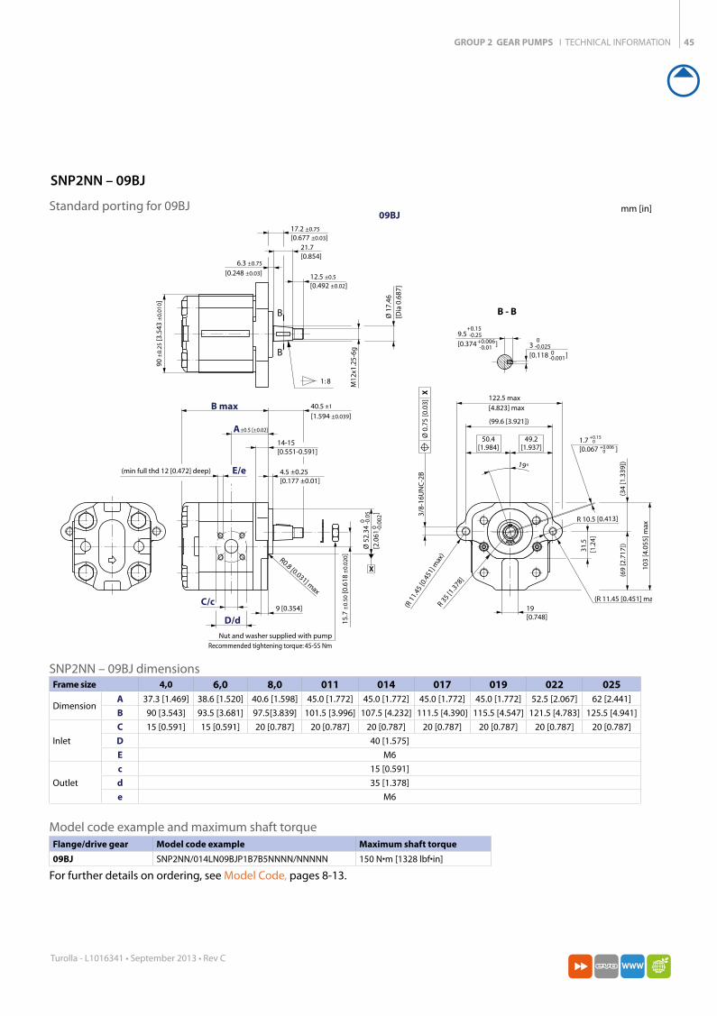
1.7 [0.067 ]
1: 8
B
B B - BØ 1
7.46
[D
ia 0
.687
]
M12
x1.2
5-6g
21.7 [0.854]
14-15 [0.551-0.591]
9 [0.354]
R 10.5 [0.413]
19°
31.5
[1.2
4]
3/8-
16U
NC
-2B
122.5 max[4.823] max
(99.6 [3.921])
103
[4.0
55] m
ax
(69
[2.7
17])
(34
[1.3
39])
19 [0.748]
(R 11.45 [0.451] max)
(R 1
1.45
[0.4
51] m
ax)
R 35 [1
.378]
49.2[1.937]
50.4[1.984]
17.2 ±0.75
[0.677 ±0.03]
40.5 [1.594 ±0.039]
±1
90 ±
0.25
[3.5
43 ±
0.01
0]
12.5 ±0.5
[0.492 ±0.02]
6.3 ±0.75
[0.248 ±0.03]
15.7
±0.
50 [0
.618
±0.
020 ]
4.5 ±0.25 [0.177 ±0.01]
9.5 [0.374 ]
+0.15
+0.006-0.25
-0.01
+0.15
+0.0060
0
3 [0.118 ]
0
0-0.025
-0.001Ø
52.
34
[2
.061
]
0
0-0
.05
-0.0
02
Ø 0
.75
[0.0
3]
X
X
(min full thd 12 [0.472] deep)
B max
A
C/c
E/e
D/d
±0.5 [±0.02]
09BJ
R0.8 [0.031] max
Nut and washer supplied with pumpRecommended tightening torque: 45-55 Nm
SNP2NN – 09BJ dimensionsFrame size 4,0 6,0 8,0 011 014 017 019 022 025
DimensionA 37.3 [1.469] 38.6 [1.520] 40.6 [1.598] 45.0 [1.772] 45.0 [1.772] 45.0 [1.772] 45.0 [1.772] 52.5 [2.067] 62 [2.441]B 90 [3.543] 93.5 [3.681] 97.5[3.839] 101.5 [3.996] 107.5 [4.232] 111.5 [4.390] 115.5 [4.547] 121.5 [4.783] 125.5 [4.941]
Inlet
C 15 [0.591] 15 [0.591] 20 [0.787] 20 [0.787] 20 [0.787] 20 [0.787] 20 [0.787] 20 [0.787] 20 [0.787]D 40 [1.575]E M6
Outlet
c 15 [0.591]d 35 [1.378]e M6
Model code example and maximum shaft torque Flange/drive gear Model code example Maximum shaft torque
09BJ SNP2NN/014LN09BJP1B7B5NNNN/NNNNN 150 N•m [1328 lbf•in]
For further details on ordering, see Model Code, pages 8-13.
SNP2NN – 09BJ
Standard porting for 09BJ mm [in]

GROUP 2 GEAR PUMPS I TECHNICAL INFORMATION46
Turolla - L1016341 • September 2013 • Rev C
SNP2NN – A9BJ dimensionsFrame size 4,0 6,0 8,0 011 014 017 019 022 025
DimensionA 37.3 [1.469] 38.6 [1.520] 40.6 [1.598] 45.0 [1.772] 45.0 [1.772] 45.0 [1.772] 45.0 [1.772] 52.5 [2.067] 62 [2.441]B 90 [3.543] 93.5 [3.681] 97.5[3.839] 101.5 [3.996] 107.5 [4.232] 111.5 [4.390] 115.5 [4.547] 121.5 [4.783] 125.5 [4.941]
Inlet
C 15 [0.591] 15 [0.591] 20 [0.787] 20 [0.787] 20 [0.787] 20 [0.787] 20 [0.787] 20 [0.787] 20 [0.787]D 40 [1.575]E M6
Outlet
c 15 [0.591]d 35 [1.378]e M6
Model code example and maximum shaft torque Flange/drive gear Model code example Maximum shaft torque
A9BJ SNP2NN/011RNA9BJP1C7C3NNNN/NNNNN 150 N•m [1328 lbf•in]
For further details on ordering, see Model Code, pages 8-13.
1:8
B
B
B - B
21.7 [0.854]
M12
x1.2
5-6g
Ø 1
7.46
[0.6
87]
3 [0.118 ]0 0-0.025 -0.001
9.5 [0.374 ]+0.15 +0.006-0.25 -0.010
90
[3.5
43
]±
0.25
±0.
010
R0.8 [0.031] max
14-15 [0.551-0.591]
3/8-
16U
NC
-2B
(99.6 [3.921])
122.5 [4.823] max
109
[4.2
91] m
ax
R38
[1.4
96] m
ax
(R11.45 [0.451] max)
13°
50.4[1.984]
49.2[1.937]
3.85 [0.152 ]
+0.15
+0.0060
0
Ø 5
2.34
[
2.06
1
]0
0-0
.05
-0.0
02
15.7
[
0.61
8
]±
0.5
±0.
02
40.5 [1.594 ]
±1
±0.039
X
Ø 0
.75
[0.0
3] X
Min. full thread12 [0.472] deep
E/e
C/c
D/d
B max
A
A9BJ
±0.5 [0.02]
4.0 ±0.50
[0.157 ±0.02]
17.2 ±0.50 [0.677 ±0.02]
6.3 ±0.75 [0.248 ±0.03]
12.5 ±0.50 [0.492 ±0.02]
Nut and washer supplied with pumpRecommended tightening torque: 45-55 Nm
SNP2NN – A9BJ
Standard porting for A9BJ mm [in]

GROUP 2 GEAR PUMPS I TECHNICAL INFORMATION
77C33M
55K 50C100Y
66M88Y
66M88Y
47
Turolla - L1016341 • September 2013 • Rev C
Notes
Orange - CMYK 88%Y 66%MGrey - CMYK 44% BlackItalyVia Villanova 2840055 Villanova di Castenaso Bologna, ItaliaTelephone: +39 051 6054 411
U.S.A.2800 East 13th StreetAmes, IA 50010, USAPhone: +1 515 239 6677Fax: +1 515 239 6618
SlovakiaKukučínova 2148-8401701 Považská Bystrica, SlovakiaPhone: +421 424 301 202Fax: +421 424 301 626
E-mail: [email protected]
Local address