ge industrial · pdf filethe spm has an optional power factor regulator containing five...
TRANSCRIPT
SPMSYNCHRONOUS MOTOR PROTECTION
AND CONTROLInstruction Manual
Software Revision: 210.000
Manual P/N: 1601-0072-A9 (GEK-113045B)
Copyright © 2008 GE Multilin
GE Multilin215 Anderson Avenue, Markham, Ontario
Canada L6E 1B3
Tel: (905) 294-6222 Fax: (905) 201-2098
Internet: http://www.GEmultilin.com
gGE Industrial Systems
GE Multilin’s Quality Manage-ment System is registered to
ISO9001:2000QMI # 005094*1601-0072-A9*

GE Multilin SPM Synchronous Motor Protection and Control i
TABLE OF CONTENTS
1. INTRODUCTION 1.1 OVERVIEW1.1.1 GENERAL DESCRIPTION ................................................................................ 1-11.1.2 FUNCTIONAL OVERVIEW................................................................................ 1-1
1.2 ORDERING1.2.1 ORDER CODES ................................................................................................ 1-31.2.2 ACCESSORIES ................................................................................................. 1-3
1.3 SPECIFICATIONS1.3.1 TECHNICAL SPECIFICATIONS........................................................................ 1-4
2. INSTALLATION 2.1 OVERVIEW2.1.1 DESCRIPTION................................................................................................... 2-12.1.2 ELEMENTS OF A SYNCHRONOUS MOTOR CONTROLLER ......................... 2-1
2.2 MECHANICAL INSTALLATION2.2.1 UNPACKING THE SPM..................................................................................... 2-22.2.2 REMOVING THE DRAWOUT RELAY ............................................................... 2-22.2.3 INSERTING THE DRAWOUT RELAY ............................................................... 2-22.2.4 MOUNTING THE SPM....................................................................................... 2-22.2.5 SPM MOUNTING ACCESSORIES.................................................................... 2-2
2.3 ELECTRICAL INSTALLATION2.3.1 DESCRIPTION................................................................................................... 2-42.3.2 GROUNDING..................................................................................................... 2-62.3.3 FIELD AND EXCITER VOLTAGE INPUTS........................................................ 2-62.3.4 RELAY OUTPUTS ............................................................................................. 2-62.3.5 CURRENT TRANSFORMER INPUT ................................................................. 2-62.3.6 POWER FACTOR OUTPUT .............................................................................. 2-62.3.7 DC FIELD CURRENT INPUT ............................................................................ 2-62.3.8 EXCITER VOLTAGE OUTPUT MONITOR........................................................ 2-62.3.9 POWER FACTOR REGULATION OUTPUT...................................................... 2-72.3.10 CONTROL VOLTAGE........................................................................................ 2-72.3.11 EXTERNAL VOLTAGE PF REFERENCE ......................................................... 2-72.3.12 RS485 COMMUNICATIONS PORT................................................................... 2-8
3. SYNCHRONOUS MOTOR APPLICATIONS
3.1 OVERVIEW3.1.1 GENERAL .......................................................................................................... 3-1
3.2 COLLECTOR-RING MOTORS3.2.1 STARTING AND SYNCHRONIZING ................................................................. 3-53.2.2 RELUCTANCE TORQUE SYNCHRONIZING ................................................... 3-63.2.3 STARTING PROTECTION ................................................................................ 3-73.2.4 REDUCED VOLTAGE STARTING .................................................................... 3-83.2.5 POWER FACTOR (PULL-OUT) PROTECTION .............................................. 3-103.2.6 POWER FACTOR OPERATION...................................................................... 3-113.2.7 CONTROLLER ACTION DURING PULL-OUT ................................................ 3-123.2.8 EFFECT OF VOLTAGE DIPS ON MOTOR POWER FACTOR....................... 3-133.2.9 POWER FACTOR DETECTION & INDICATION – OVERHAULING LOAD.... 3-153.2.10 POWER FACTOR REGULATION ................................................................... 3-16
3.3 BRUSHLESS CONTROLLER3.3.1 DESCRIPTION................................................................................................. 3-173.3.2 BRUSHLESS MOTOR REVIEW...................................................................... 3-173.3.3 STARTING THE BRUSHLESS MOTOR.......................................................... 3-183.3.4 STALL PROTECTION...................................................................................... 3-193.3.5 POWER FACTOR (PULL-OUT) PROTECTION .............................................. 3-193.3.6 POWER FACTOR REGULATION ................................................................... 3-19
4. USER INTERFACE 4.1 SPMPC SOFTWARE4.1.1 DESCRIPTION................................................................................................... 4-1
ii SPM Synchronous Motor Protection and Control GE Multilin
TABLE OF CONTENTS
4.1.2 SPMPC INSTALLATION ....................................................................................4-24.1.3 CONFIGURATION..............................................................................................4-34.1.4 CREATING A NEW SETPOINT FILE.................................................................4-44.1.5 EDITING A SETPOINT FILE ..............................................................................4-54.1.6 LOADING SETPOINTS FROM A FILE...............................................................4-64.1.7 UPGRADING SETPOINT FILES TO A NEW REVISION ...................................4-74.1.8 PRINTING SETPOINTS & ACTUAL VALUES....................................................4-84.1.9 TRENDING .........................................................................................................4-9
4.2 KEYPAD INTERFACE4.2.1 DESCRIPTION .................................................................................................4-104.2.2 CHANGING SETPOINTS .................................................................................4-114.2.3 CHANGING CALIBRATION VALUES ..............................................................4-124.2.4 CHANGING CONFIGURATIONS.....................................................................4-134.2.5 VIEWING & CHANGING STATUS MODE PARAMETERS..............................4-144.2.6 ALTERNATE MENU OPERATION...................................................................4-14
5. SETPOINTS 5.1 OVERVIEW5.1.1 DESCRIPTION ...................................................................................................5-1
5.2 SETPOINTS MENU5.2.1 POWER FACTOR TRIP .....................................................................................5-25.2.2 POWER FACTOR DELAY..................................................................................5-25.2.3 POWER FACTOR SUPRESSION......................................................................5-25.2.4 POWER FACTOR MODE...................................................................................5-35.2.5 FIELD APPLICATION RELAY DELAY ...............................................................5-35.2.6 FIELD CONTACTOR AUXILIARY RELAY DELAY.............................................5-35.2.7 AC CT PRIMARY RATING .................................................................................5-45.2.8 MOTOR FULL LOAD AMPS...............................................................................5-45.2.9 MOTOR LOCKED ROTOR AMPS......................................................................5-45.2.10 SYNCHRONOUS SLIP.......................................................................................5-55.2.11 STALL TIME .......................................................................................................5-55.2.12 RUN TIME ..........................................................................................................5-55.2.13 DIRECT CURRENT CT PRIMARY RATING ......................................................5-65.2.14 FIELD OVERTEMPERATURE (HIGH FIELD OHMS) PROTECTION ...............5-75.2.15 FIELD UNDERCURRENT ..................................................................................5-85.2.16 FIELD UNDERCURRENT DELAY......................................................................5-85.2.17 FIELD UNDERVOLTAGE...................................................................................5-85.2.18 FIELD UNDERVOLTAGE DELAY ......................................................................5-95.2.19 INCOMPLETE SEQUENCE DELAY ..................................................................5-9
5.3 OPTIONAL POWER FACTOR REGULATION SETPOINTS5.3.1 DESCRIPTION .................................................................................................5-105.3.2 POWER FACTOR REGULATOR .....................................................................5-105.3.3 REGULATOR GAIN..........................................................................................5-105.3.4 STABILITY........................................................................................................5-105.3.5 REGULATOR OUTPUT LIMIT .........................................................................5-115.3.6 FLOOR VOLTS.................................................................................................5-11
5.4 CONFIGURATIONS MENU5.4.1 MOTOR TYPE ..................................................................................................5-125.4.2 LINE FREQUENCY ..........................................................................................5-125.4.3 POWER FACTOR REFERENCE .....................................................................5-125.4.4 RTU ADDRESS ................................................................................................5-125.4.5 BAUD RATE .....................................................................................................5-125.4.6 PARITY.............................................................................................................5-125.4.7 TURNAROUND ................................................................................................5-135.4.8 STATUS MODE................................................................................................5-135.4.9 PASSWORD.....................................................................................................5-13
5.5 CALIBRATION MENU5.5.1 FULL-SCALE EXCITER DC VOLTAGE ...........................................................5-145.5.2 FULL-SCALE EXCITER DC AMPS ..................................................................5-145.5.3 FULL-SCALE MOTOR AC AMPS ....................................................................5-14
GE Multilin SPM Synchronous Motor Protection and Control iii
TABLE OF CONTENTS
6. ACTUAL VALUES 6.1 DISPLAY SCROLLING6.1.1 DESCRIPTION................................................................................................... 6-1
6.2 STATUS6.2.1 MOTOR RUNNING HOURS .............................................................................. 6-26.2.2 INCOMPLETE SEQUENCE TRIP COUNTER................................................... 6-26.2.3 FIELD LOSS TRIP COUNTER .......................................................................... 6-26.2.4 PULL-OUT TRIP COUNTER ............................................................................. 6-26.2.5 RESYNCRONIZATION ATTEMPTS TRIP COUNTER...................................... 6-26.2.6 MISSING EXTERNAL PF VOLTAGE REFERENCE COUNTER ...................... 6-26.2.7 CHECK EXCITER TRIP COUNTER .................................................................. 6-36.2.8 POWER FACTOR TRIP COUNTER.................................................................. 6-36.2.9 SQUIRREL CAGE TRIP COUNTER.................................................................. 6-36.2.10 FIELD OVERVOLTAGE TRIP COUNTER......................................................... 6-3
7. TESTING AND TROUBLESHOOTING
7.1 START-UP PROCEDURE7.1.1 INSPECTION ..................................................................................................... 7-17.1.2 SPM TEST CHECKS ......................................................................................... 7-17.1.3 START-UP DESCRIPTION................................................................................ 7-2
7.2 DISPLAY AND MESSAGES7.2.1 DISPLAY ............................................................................................................ 7-37.2.2 SPM MESSAGES .............................................................................................. 7-3
7.3 REGULATOR TUNE-UP7.3.1 INSTRUCTIONS ................................................................................................ 7-5
7.4 TROUBLESHOOTING7.4.1 TROUBLESHOOTING GUIDE........................................................................... 7-6
7.5 PROGRAMMING7.5.1 PROGRAMMING EXAMPLE ............................................................................. 7-8
7.6 DOS AND DON’TS7.6.1 DOS ................................................................................................................. 7-127.6.2 DON'TS............................................................................................................ 7-12
7.7 FREQUENTLY ASKED QUESTIONS7.7.1 SPM FAQ ......................................................................................................... 7-13
7.8 REVISION HISTORY7.8.1 FIRMWARE...................................................................................................... 7-15
8. ACCESSORIES 8.1 VOLTAGE DIVIDER NETWORK8.1.1 GE MULTILIN VDN ............................................................................................ 8-18.1.2 GE MEBANE VDN ............................................................................................. 8-2
8.2 FIELD CURRENT CALIBRATION MODULE8.2.1 GE MULTILIN MODULE .................................................................................... 8-3
8.3 DC CURRENT TRANSFORMER8.3.1 DESCRIPTION................................................................................................... 8-6
9. MODBUS COMMUNICATIONS
9.1 IMPLEMENTATION9.1.1 MODBUS PROTOCOL ...................................................................................... 9-19.1.2 PERFORMANCE REQUIREMENTS ................................................................. 9-19.1.3 SETPOINTS....................................................................................................... 9-19.1.4 EXECUTE OPERATION COMMAND CODES (COIL NUMBERS) ................... 9-1
9.2 MEMORY MAPPING9.2.1 MODBUS MEMORY MAP ................................................................................. 9-29.2.2 FORMAT CODES .............................................................................................. 9-7
iv SPM Synchronous Motor Protection and Control GE Multilin
TABLE OF CONTENTS
10. FUNCTIONAL TESTS 10.1 INTRODUCTION10.1.1 DESCRIPTION .................................................................................................10-1
10.2 COLLECTOR-RING MOTOR FIELD APPLICATION TEST10.2.1 SETUP..............................................................................................................10-210.2.2 RELAY PROGRAMMING .................................................................................10-210.2.3 TEST.................................................................................................................10-2
10.3 COLLECTOR-RING MOTOR POWER FACTOR TEST10.3.1 SETUP..............................................................................................................10-310.3.2 RELAY PROGRAMMING .................................................................................10-310.3.3 TEST.................................................................................................................10-3
10.4 COLLECTOR-RING MOTOR POWER FACTOR TRIP TEST10.4.1 SETUP..............................................................................................................10-410.4.2 RELAY PROGRAMMING .................................................................................10-410.4.3 TEST.................................................................................................................10-4
10.5 BRUSHLESS MOTOR FIELD APPLICATION TEST10.5.1 SETUP..............................................................................................................10-510.5.2 RELAY PROGRAMMING .................................................................................10-510.5.3 TEST.................................................................................................................10-5
10.6 BRUSHLESS MOTOR POWER FACTOR TEST10.6.1 SETUP..............................................................................................................10-610.6.2 RELAY PROGRAMMING .................................................................................10-610.6.3 TEST.................................................................................................................10-6
10.7 BRUSHLESS MOTOR POWER FACTOR TRIP TEST10.7.1 SETUP..............................................................................................................10-710.7.2 RELAY PROGRAMMING .................................................................................10-710.7.3 TEST.................................................................................................................10-7
10.8 AC CURRENT METERING AND PULL-OUT TEST10.8.1 SETUP..............................................................................................................10-810.8.2 RELAY PROGRAMMING .................................................................................10-810.8.3 TEST.................................................................................................................10-8
10.9 EXCITER / FIELD VOLTAGE METERING TEST10.9.1 SETUP..............................................................................................................10-910.9.2 RELAY PROGRAMMING .................................................................................10-910.9.3 TEST.................................................................................................................10-9
10.10 EXCITER / FIELD CURRENT METERING TEST10.10.1 SETUP............................................................................................................10-1010.10.2 RELAY PROGRAMMING ...............................................................................10-1010.10.3 TEST...............................................................................................................10-10
A. COMMISSIONING A.1 COMMISSIONINGA.1.1 COLLECTOR-RING SETTINGS........................................................................ A-1A.1.2 BRUSHLESS SETTINGS .................................................................................. A-2
B. WARRANTY B.1 WARRANTYB.1.1 WARRANTY ...................................................................................................... B-1
GE Multilin SPM Synchronous Motor Protection and Control 1-1
1 INTRODUCTION 1.1 OVERVIEW
11 INTRODUCTION 1.1 OVERVIEW 1.1.1 GENERAL DESCRIPTION
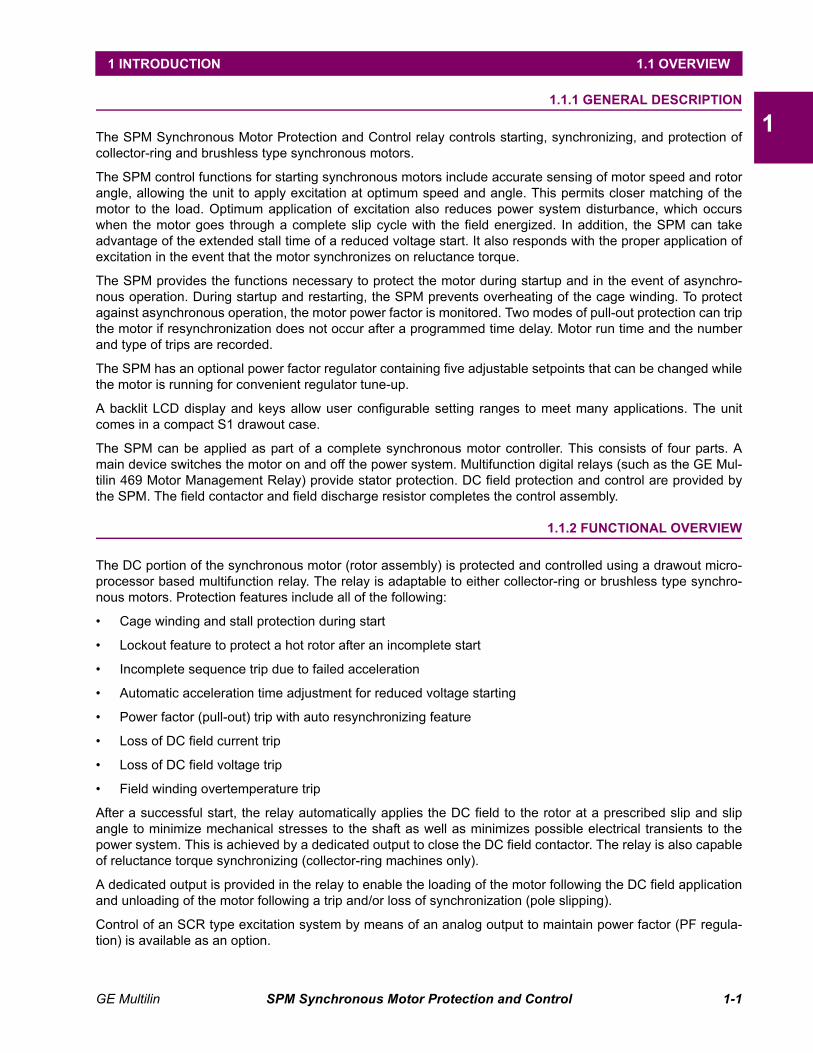
The SPM Synchronous Motor Protection and Control relay controls starting, synchronizing, and protection ofcollector-ring and brushless type synchronous motors.
The SPM control functions for starting synchronous motors include accurate sensing of motor speed and rotorangle, allowing the unit to apply excitation at optimum speed and angle. This permits closer matching of themotor to the load. Optimum application of excitation also reduces power system disturbance, which occurswhen the motor goes through a complete slip cycle with the field energized. In addition, the SPM can takeadvantage of the extended stall time of a reduced voltage start. It also responds with the proper application ofexcitation in the event that the motor synchronizes on reluctance torque.
The SPM provides the functions necessary to protect the motor during startup and in the event of asynchro-nous operation. During startup and restarting, the SPM prevents overheating of the cage winding. To protectagainst asynchronous operation, the motor power factor is monitored. Two modes of pull-out protection can tripthe motor if resynchronization does not occur after a programmed time delay. Motor run time and the numberand type of trips are recorded.
The SPM has an optional power factor regulator containing five adjustable setpoints that can be changed whilethe motor is running for convenient regulator tune-up.
A backlit LCD display and keys allow user configurable setting ranges to meet many applications. The unitcomes in a compact S1 drawout case.
The SPM can be applied as part of a complete synchronous motor controller. This consists of four parts. Amain device switches the motor on and off the power system. Multifunction digital relays (such as the GE Mul-tilin 469 Motor Management Relay) provide stator protection. DC field protection and control are provided bythe SPM. The field contactor and field discharge resistor completes the control assembly.
1.1.2 FUNCTIONAL OVERVIEW
The DC portion of the synchronous motor (rotor assembly) is protected and controlled using a drawout micro-processor based multifunction relay. The relay is adaptable to either collector-ring or brushless type synchro-nous motors. Protection features include all of the following:
• Cage winding and stall protection during start
• Lockout feature to protect a hot rotor after an incomplete start
• Incomplete sequence trip due to failed acceleration
• Automatic acceleration time adjustment for reduced voltage starting
• Power factor (pull-out) trip with auto resynchronizing feature
• Loss of DC field current trip
• Loss of DC field voltage trip
• Field winding overtemperature trip
After a successful start, the relay automatically applies the DC field to the rotor at a prescribed slip and slipangle to minimize mechanical stresses to the shaft as well as minimizes possible electrical transients to thepower system. This is achieved by a dedicated output to close the DC field contactor. The relay is also capableof reluctance torque synchronizing (collector-ring machines only).
A dedicated output is provided in the relay to enable the loading of the motor following the DC field applicationand unloading of the motor following a trip and/or loss of synchronization (pole slipping).
Control of an SCR type excitation system by means of an analog output to maintain power factor (PF regula-tion) is available as an option.
1-2 SPM Synchronous Motor Protection and Control GE Multilin
1.1 OVERVIEW 1 INTRODUCTION
1The man-machine interface (MMI) consists of a backlit alphanumeric display and a keypad to accommodaterelay programming as well as viewing actual motor parameters which comprise:
• AC stator current
• Power factor
• DC field current
• DC field voltage
• DC field resistance
• Running time meter (RTM)
Statistical data includes number and type of trips.
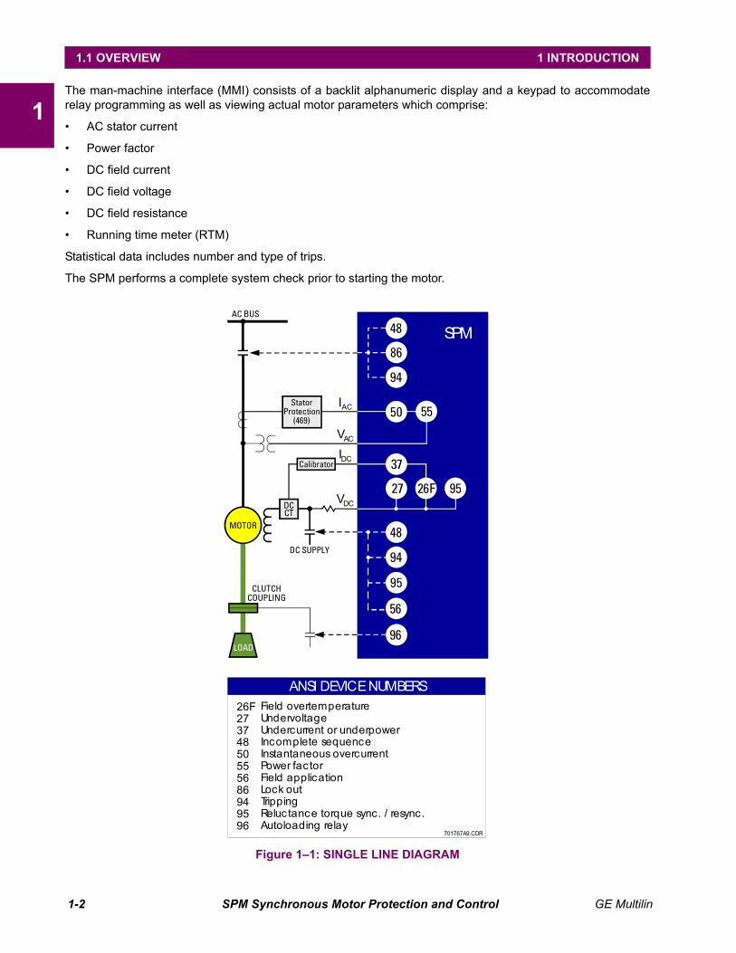
The SPM performs a complete system check prior to starting the motor.
Figure 1–1: SINGLE LINE DIAGRAM
701767A9.CDR
MOTOR
LOAD
AC BUS
CLUTCHCOUPLING
DC SUPPLY
27 26F 95
96
56
95
48
94
86
94
48
55
SPM
StatorProtection(469)
Calibrator
DCCT
37
50IAC
VDC
IDC
VAC
ANSI DEVICENUMBERSField overtemperatureUndervoltageUndercurrent or underpowerIncomplete sequenceInstantaneous overcurrentPower factorField applicationLock outTrippingReluctance torque sync. / resync.Autoloading relay
26F27374850555686949596

GE Multilin SPM Synchronous Motor Protection and Control 1-3
1 INTRODUCTION 1.2 ORDERING
11.2 ORDERING 1.2.1 ORDER CODES
The SPM has all features built into the standard relay and programmable by the user to fit the specific applica-tion. The only option in the order code is for Power Factor Regulation. Some of the standard features requirean optional external hardware package that must be ordered in addition to the relay itself. These separatepackages are explained in the following section.
1.2.2 ACCESSORIES
• PG2SPM: External hardware package for overtemperature and current loss protection up to 200 A(includes 1-DCCT200 and 1-CM)
• PG4SPM: External hardware package for overtemperature and current loss protection up to 400 A(includes 1-DCCT400 or DCCT500 and 1-CM)
• MSPM: Mounting panel to retrofit existing µSPM cutouts for SPM
SPM – * – *Base Unit SPM | |Configuration 0 | Standard starting and protection relay with VDN board
PF | Power Factor regulation option. Used on motors with SCR exciter(not recommended for brushless applications)
Harsh Environment 0 Standard meterH Harsh (chemical) environment conformal coating
1-4 SPM Synchronous Motor Protection and Control GE Multilin
1.3 SPECIFICATIONS 1 INTRODUCTION
11.3 SPECIFICATIONS 1.3.1 TECHNICAL SPECIFICATIONS
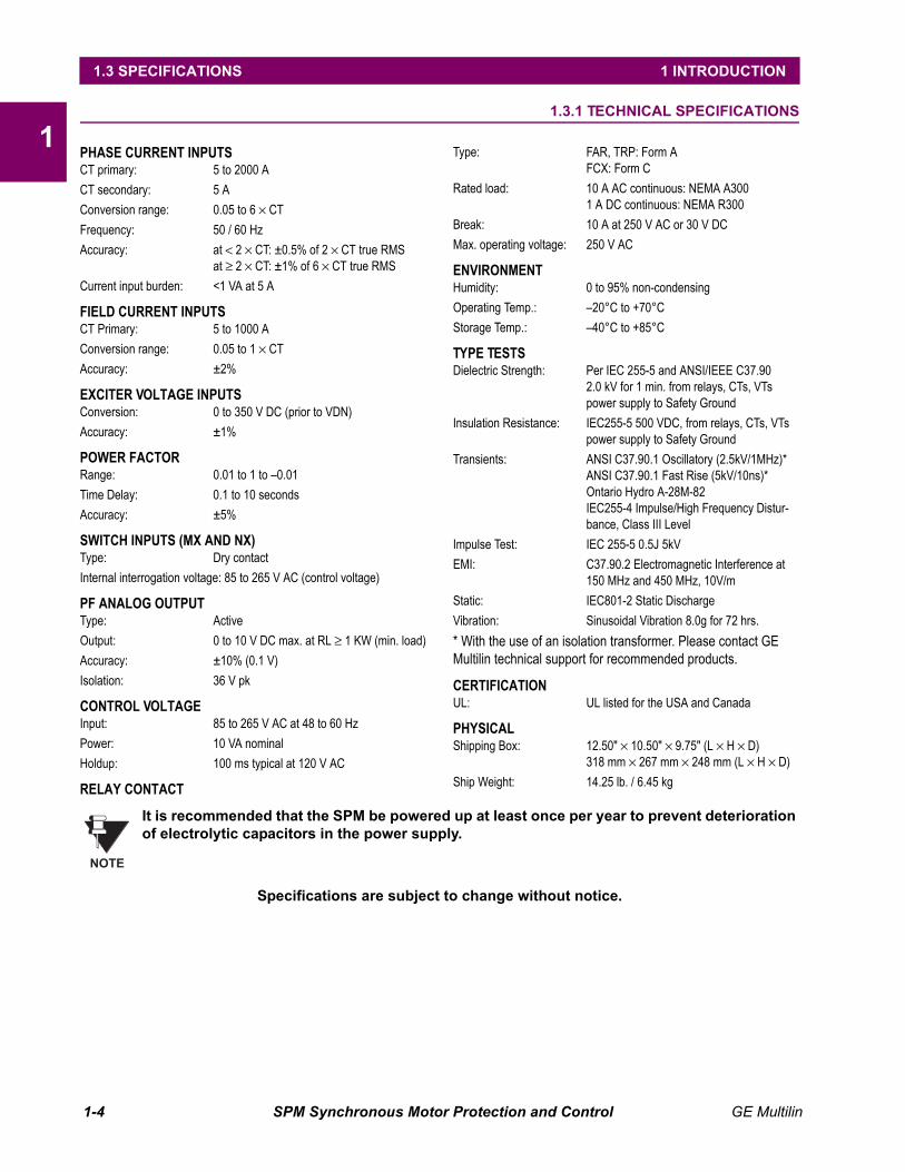
PHASE CURRENT INPUTSCT primary: 5 to 2000 ACT secondary: 5 AConversion range: 0.05 to 6 × CTFrequency: 50 / 60 HzAccuracy: at < 2 × CT: ±0.5% of 2 × CT true RMS
at ≥ 2 × CT: ±1% of 6 × CT true RMSCurrent input burden: <1 VA at 5 A
FIELD CURRENT INPUTSCT Primary: 5 to 1000 AConversion range: 0.05 to 1 × CTAccuracy: ±2%
EXCITER VOLTAGE INPUTSConversion: 0 to 350 V DC (prior to VDN)Accuracy: ±1%
POWER FACTORRange: 0.01 to 1 to –0.01Time Delay: 0.1 to 10 secondsAccuracy: ±5%
SWITCH INPUTS (MX AND NX)Type: Dry contactInternal interrogation voltage: 85 to 265 V AC (control voltage)
PF ANALOG OUTPUTType: ActiveOutput: 0 to 10 V DC max. at RL ≥ 1 KW (min. load)Accuracy: ±10% (0.1 V)Isolation: 36 V pk
CONTROL VOLTAGEInput: 85 to 265 V AC at 48 to 60 HzPower: 10 VA nominalHoldup: 100 ms typical at 120 V AC
RELAY CONTACT
Type: FAR, TRP: Form AFCX: Form C
Rated load: 10 A AC continuous: NEMA A3001 A DC continuous: NEMA R300
Break: 10 A at 250 V AC or 30 V DCMax. operating voltage: 250 V AC
ENVIRONMENTHumidity: 0 to 95% non-condensingOperating Temp.: –20°C to +70°CStorage Temp.: –40°C to +85°C
TYPE TESTSDielectric Strength: Per IEC 255-5 and ANSI/IEEE C37.90
2.0 kV for 1 min. from relays, CTs, VTspower supply to Safety Ground
Insulation Resistance: IEC255-5 500 VDC, from relays, CTs, VTspower supply to Safety Ground
Transients: ANSI C37.90.1 Oscillatory (2.5kV/1MHz)*ANSI C37.90.1 Fast Rise (5kV/10ns)*Ontario Hydro A-28M-82IEC255-4 Impulse/High Frequency Distur-bance, Class III Level
Impulse Test: IEC 255-5 0.5J 5kVEMI: C37.90.2 Electromagnetic Interference at
150 MHz and 450 MHz, 10V/mStatic: IEC801-2 Static DischargeVibration: Sinusoidal Vibration 8.0g for 72 hrs.* With the use of an isolation transformer. Please contact GE Multilin technical support for recommended products.
CERTIFICATIONUL: UL listed for the USA and Canada
PHYSICALShipping Box: 12.50" × 10.50" × 9.75" (L × H × D)
318 mm × 267 mm × 248 mm (L × H × D)Ship Weight: 14.25 lb. / 6.45 kg
It is recommended that the SPM be powered up at least once per year to prevent deterioration of electrolytic capacitors in the power supply.
Specifications are subject to change without notice.
NOTE
GE Multilin SPM Synchronous Motor Protection and Control 2-1
2 INSTALLATION 2.1 OVERVIEW
2
2 INSTALLATION 2.1 OVERVIEW 2.1.1 DESCRIPTION
The SPM can be incorporated in synchronous motor control equipment as a complete controller (including anAC power-switching device for the motor starter) or as a field panel (AC power switching supplied by otherdevice).
2.1.2 ELEMENTS OF A SYNCHRONOUS MOTOR CONTROLLER
A complete synchronous-motor controller has the ability to switch the motor on to and off of the power systemand protect the motor from damage that can occur if the motor is running in an abnormal condition such as out-of-synchronization.
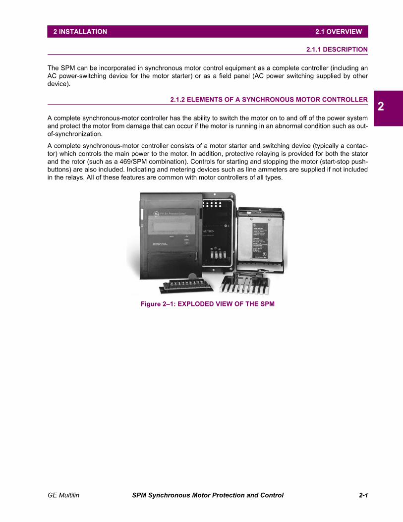
A complete synchronous-motor controller consists of a motor starter and switching device (typically a contac-tor) which controls the main power to the motor. In addition, protective relaying is provided for both the statorand the rotor (such as a 469/SPM combination). Controls for starting and stopping the motor (start-stop push-buttons) are also included. Indicating and metering devices such as line ammeters are supplied if not includedin the relays. All of these features are common with motor controllers of all types.
Figure 2–1: EXPLODED VIEW OF THE SPM
2-2 SPM Synchronous Motor Protection and Control GE Multilin
2.2 MECHANICAL INSTALLATION 2 INSTALLATION
2
2.2 MECHANICAL INSTALLATION 2.2.1 UNPACKING THE SPM
When the SPM is shipped separately, carefully unpack the module and report any observable damage or miss-ing components to the carrier and to GE Multilin. All included parts are shown in Figure 2–1: EXPLODED VIEWOF THE SPM on page 2–1.
2.2.2 REMOVING THE DRAWOUT RELAY
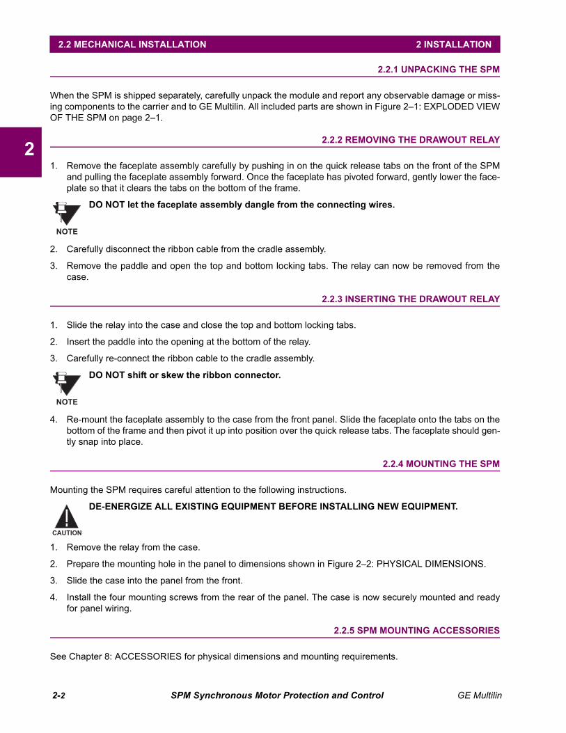
1. Remove the faceplate assembly carefully by pushing in on the quick release tabs on the front of the SPMand pulling the faceplate assembly forward. Once the faceplate has pivoted forward, gently lower the face-plate so that it clears the tabs on the bottom of the frame.
DO NOT let the faceplate assembly dangle from the connecting wires.
2. Carefully disconnect the ribbon cable from the cradle assembly.
3. Remove the paddle and open the top and bottom locking tabs. The relay can now be removed from thecase.
2.2.3 INSERTING THE DRAWOUT RELAY
1. Slide the relay into the case and close the top and bottom locking tabs.
2. Insert the paddle into the opening at the bottom of the relay.
3. Carefully re-connect the ribbon cable to the cradle assembly.
DO NOT shift or skew the ribbon connector.
4. Re-mount the faceplate assembly to the case from the front panel. Slide the faceplate onto the tabs on thebottom of the frame and then pivot it up into position over the quick release tabs. The faceplate should gen-tly snap into place.
2.2.4 MOUNTING THE SPM
Mounting the SPM requires careful attention to the following instructions.
DE-ENERGIZE ALL EXISTING EQUIPMENT BEFORE INSTALLING NEW EQUIPMENT.
1. Remove the relay from the case.
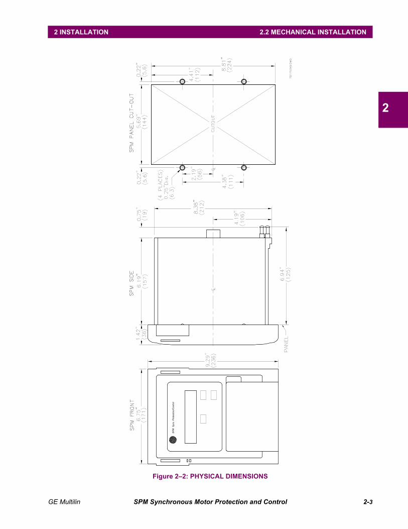
2. Prepare the mounting hole in the panel to dimensions shown in Figure 2–2: PHYSICAL DIMENSIONS.
3. Slide the case into the panel from the front.
4. Install the four mounting screws from the rear of the panel. The case is now securely mounted and readyfor panel wiring.
2.2.5 SPM MOUNTING ACCESSORIES
See Chapter 8: ACCESSORIES for physical dimensions and mounting requirements.
NOTE
NOTE
CAUTION
GE Multilin SPM Synchronous Motor Protection and Control 2-3
2 INSTALLATION 2.2 MECHANICAL INSTALLATION
2
Figure 2–2: PHYSICAL DIMENSIONS
SP
MS
ync.
Pro
tect
ion/
Con
trol
2-4 SPM Synchronous Motor Protection and Control GE Multilin
2.3 ELECTRICAL INSTALLATION 2 INSTALLATION
2
2.3 ELECTRICAL INSTALLATION 2.3.1 DESCRIPTION
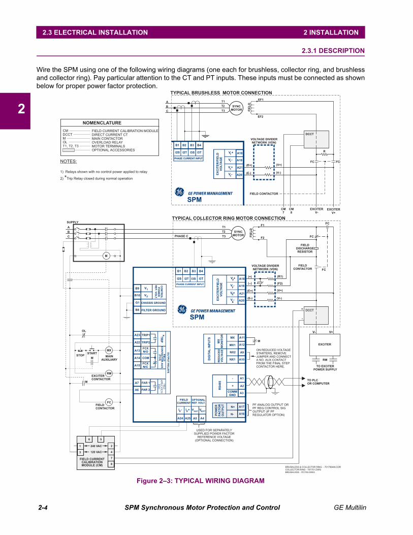
Wire the SPM using one of the following wiring diagrams (one each for brushless, collector ring, and brushlessand collector ring). Pay particular attention to the CT and PT inputs. These inputs must be connected as shownbelow for proper power factor protection.
Figure 2–3: TYPICAL WIRING DIAGRAM
USED FOR SEPARATELYSUPPLIED POWER FACTOR
REFERENCE VOLTAGE(OPTIONAL CONNECTION)
STOPSTART
MAIN
AUXILIARYM
M
EXCITER
CONTACTOR
M
OL
SUPPLY
C
B
A
TYPICAL COLLECTOR RING MOTOR CONNECTION
T1
PHASE C T3
T2
(+)
F1
FIE
LD
FIELD
DISCHARGE
RESISTOR
FIELD
CONTACTOR
FC
FC
EXCITER
V+
EXCITER
V-
CM
8
CM
7
FC
F2
(R1)
(F2)
(E+) (V+)
(E-) (V-)
+
-
VOLTAGE DIVIDER
NETWORK (VDN)
A17
A16
N+
N-PO
WE
R
FA
CT
OR
OU
TP
UT
V1
V2
B9
G1
B8
B10
CO
NT
RO
L
PO
WE
R
RE
F.V
OLT.
CHASSIS GROUND
FILTER GROUND
A21
A20
V +
V -
A18
A19
V +F
F
E
E
V -
EX
CIT
ER
/FIE
LD
VO
LTA
GE
FIELD
CURRENT
OPTIONAL
REF. VOLT.
A5 A4
V V
A24 A25
I - I +EE 1EXT 2EXT
RE
DU
CE
D
VO
LTA
GE
DIG
ITA
LIN
PU
TS
RS
48
5
A11
A12
A1
MX
MX1
-
MX
MO
NIT
OR
A9
A2
NX2
+
A10
A3
NX1
COMM
GND
SYNC
MOTOR
PF ANALOG OUTPUT ORPF REG CONTROL SIGOUTPUT (IF PFREGULATOR OPTION)
ON REDUCED VOLTAGESTARTERS, REMOVEJUMPER AND CONNECTA NO. AUX CONTACTFROM THE FINAL STEPCONTACTOR HERE.
DCCT
V+V-
RM
EXCITER
TO EXCITER
POWER SUPPLY
TO PLC
OR COMPUTER
BRUSHLESS & COLLECTOR RING - 701756AN.CDRCOLLECTOR RING - 701751.DWG
BRUSHLESS - 701753.DWG
( )
B1
I2S I2T
PHASE CURRENT INPUT
B2 B4B3
I3TI3S
FCFIELD
CONTACTOR
RM
MX
NOTES:
1) Relays shown with no control power applied to relay
2) Trip Relay closed during normal operation*
FIELD CURRENT CALIBRATION MODULEDIRECT CURRENT CTMAIN CONTACTOROVERLOAD RELAYMOTOR TERMINALSOPTIONAL ACCESSORIES
CMDCCTMOLT1, T2, T3
NOMENCLATURE
FIELD CURRENT
CALIBRATION
MODULE (CM)
240 VAC
120 VAC
6 5
21
43
8
7
FIELD CONTACTOR
TYPICAL BRUSHLESS MOTOR CONNECTION
T1
T3
T2
EF1
FIE
LD
FC FC
R
EF2
(E+) (V+)
(E-) (V-)
VOLTAGE DIVIDER
NETWORK (VDN)
SYNC
MOTOR
A18
A19
V +F
FV -
EX
CIT
ER
/FIE
LD
VO
LTA
GE
A21
A20
V +
V -E
E
A
B
C
B1
PHASE CURRENT INPUT
B2 B4
I2T
B3
I2S I3S I3T
DCCT
A13
A14
A15
COM
FCX
N/C
FIE
LD
CO
NTA
CT
OR
AU
X.
(FC
X)
A22
A23
*T
RIP
OU
TP
UT
RE
LA
YS
FCX
N/O
TRIP1
TRIP2
A6
A7 FIELDA
PPLICATIO
N(FA
R)
FAR 1
FAR 2
M
SPM
GE POWER MANAGEMENT
SPM
GE POWER MANAGEMENT

GE Multilin SPM Synchronous Motor Protection and Control 2-5
2 INSTALLATION 2.3 ELECTRICAL INSTALLATION
2
Figure 2–4: PANEL AND TERMINAL LAYOUT
AC AmpsPower FactorDC AmpsDC Volts(Exciter) Field Ohms
Power Factor TripPower Factor Trip DelayPower Factor Suppression
FCX Delay
Power Factor ModeFAR Delay
DISPLAY FUNCTIONS
DISPLAY SCROLL SETPOINT SCROLL
CONTRAST
AC CT RatingFull Load AmpsLocked Rotor AmpsSync. Slip
Run TimeStall Time
DC CT PrimaryHigh (Exciter) Field Ohms(Exciter) Field Amps(Exciter) Field VoltsIncomplete Sequence DelayRegulator Power FactorRegulator GainRegulator StabilityRegulator OutputRegulator Floor Volts
Items in and white come standard.green
Items in green are motor type dependent.Items in yellow are optional.
12
34
56
78
910
1112
1314
1516
1718
1920
2122
2324
2526
2728
FRONT VIEW
REAR VIEW
701750AF.CDR
Used to remove display for easyaccess to drawout.
Lightens or darkens display.
Hides menu when not in use.
CONTRAST DIAL
PULLDOWN DOOR
85 to 265VAC.
CONTROL POWER
A wire lead seal can be used toprevent unauthorized removalof relay.
LOCKING PROVISION
Menu of all accessible setpointsand actual values for easy reference.
Compact S1 rugged metal/bakelitecase. Fits standard cutout.
2 Phase current inputs.Accept #8 wire.
DISPLAY FUNCTION MENU
S1 CASE
MOTOR LINE CURRENT
QUICK RELEASE TABS
A
B
A
1
1 2 3 4 5 6 7 8 9 10I2S I2T I3S I3T
2
3
4
5
6
7
8
9
10
11
12
13
14
15
16
17
18
19
20
21
22
23
24
25
26
27
28
RS
48
5-
RS
48
5+
RS
485
GN
D
NX
2
NX
1
MX
1
N-
N+
V+
FV
-F
V-
EV
+E
I-
E
NC
NC
NC
I+
E NC
SPM Sync. Protection/Control
SCROLL
ENTER
TRIP: Normally open,failsafe trip relay.
FAR: Field applicationrelay.
FCX: Autoloading of themotor.
EXCITER: Exciter voltageinputs. Connected viaDCCT and CM.
REDUCED VOLTAGE:Contact input forreduced voltage starting.Motor "ON" input.Exciter current input.Power Factor referencevoltage (for seperatelypowered option).
POWER FACTOR:0-10VDC analog signal.
FIELD: DC field voltageinput.
RELAYS
INPUTS
OUTPUTS
TERMINAL BLOCK A
Used to enter or exit the differentmodes of the SPM. These areStandby, Test, Statistics andProgramming modes.
GE KEY
Used to make a selection or actsas an enter key.
ENTER KEYUsed to scroll through the variousmenus and change setpointparameter values.
SCROLL KEYS
Back lit 32 character display forsetpoints, actual values and status.Programmable auto scan sequencefor unattended operation.
LCD DISPLAY
V1FILTER
GNDV2
V2E
XT
V1E
XT
FA
R2
FA
R1
MX
FC
XN
/O
FC
XC
OM
FC
XN
/C
TR
P2
TR
P1
Motor HoursISP Trip CtrFLP Trip CtrPO Trip CtrResync CtrNO V Trp CtrExc Trip CtrPF Trip CtrSCP Trip CtrFOT Trip Ctr
STAT SCROLL

2-6 SPM Synchronous Motor Protection and Control GE Multilin
2.3 ELECTRICAL INSTALLATION 2 INSTALLATION
2
2.3.2 GROUNDING
The SPM relay must be solidly grounded to a suitable system ground. Extensive filtering and transient protec-tion has been built into the SPM to ensure proper and reliable operation in harsh industrial environments.Proper grounding of the chassis ground terminal is critical to en-sure safety and filtering.
2.3.3 FIELD AND EXCITER VOLTAGE INPUTS
The field voltage inputs (VF + and VF –) and exciter voltage inputs (VE + and VE –) are connected to the relayvia the supplied voltage divider network (VDN).
DO NOT ATTEMPT TO START THE MOTOR WITHOUT THE EXTERNAL RESISTOR ASSEMBLYWIRED. SEVERE DAMAGE TO THE SPM MAY RESULT IF THE EXTERNAL RESISTOR ASSEM-BLY IS NOT PROPERLY CONNECTED.
2.3.4 RELAY OUTPUTS
The following is a description of the relay outputs.
1. TRIP: Trip Relay. This relay is normally energized and drops out on loss of power or when the modulesenses an abnormal condition.
2. FAR: Field Application Relay. This relay picks up at the proper time to apply DC to the motor field.
3. FCX: Loading Relay. This relay picks up when the motor is fully synchronized and ready to be loaded. It iscontrolled by the "FCX Delay" programmable setpoint.
2.3.5 CURRENT TRANSFORMER INPUT
The SPM is designed to work from a five ampere (5 A) current transformer (CT) secondary. The current trans-former must be connected in the proper motor phase. See Figure 2–3: TYPICAL WIRING DIAGRAM on page2–4 to determine proper phase. For brushless applications, the SPM requires inputs from two motor phases.
2.3.6 POWER FACTOR OUTPUT
This output is a 0 to 10 V DC signal that corresponds linearly to phase shift, and sinusoidal to motor power fac-tor. 0 V is zero lagging power factor, 5 V is unity power factor, and 10 V is zero leading power factor.
Calibration: 1 volt change corresponds to an 18° phase shift (not available with power factor regulation). Do notconnect less than 1000 Ω to this output.
2.3.7 DC FIELD CURRENT INPUT
DC field input must be sensed from a separately purchased DCCT (Direct Current, Current Transformer) andCM (Calibration Module).
2.3.8 EXCITER VOLTAGE OUTPUT MONITOR
The output of the field exciter must be connected to the SPM through a separate resistor when exciter voltagefailure protection and/or exciter voltage display is required.
CAUTION

GE Multilin SPM Synchronous Motor Protection and Control 2-7
2 INSTALLATION 2.3 ELECTRICAL INSTALLATION
2
2.3.9 POWER FACTOR REGULATION OUTPUT
This optional output replaces the power factor analog signal output. It consists of a 0 to 10 V DC control signalwhich is used to control an SCR Variable Exciter output to obtain motor power factor regulation.
2.3.10 CONTROL VOLTAGE
If control voltage excursions occur outside the range of 85 to 265 V AC, a provision is available that will allowthe user to connect an external stabilizing transformer for operation with severe control power voltage dips.The SPM has separate inputs for control power and power factor reference voltage. This allows connection forcontrol power from a stabilized voltage source of 115 V AC or 230 V AC. Terminal points "V1EXT" and "V2EXT"have been added to accommodate the separate PF reference voltage.
2.3.11 EXTERNAL VOLTAGE PF REFERENCE
When terminal points "V1EXT" and "V2EXT" are used to accommodate a separate PF reference voltage, asdescribed above, a standard protective function will alert the user should this external voltage drop below theacceptable limits for the SPM power supply. This protection will not allow the motor to start while the externalvoltage is missing, but the SPM will not require a reset before the motor can be restarted. If the external refer-ence voltage is lost while the motor is running, the SPM will trip the motor and will require a reset before themotor can be restarted. "MISSING VOLTAGE!" will be displayed until reset.
Figure 2–5: REFERENCE VOLTAGE INPUT CONNECTIONS
2-8 SPM Synchronous Motor Protection and Control GE Multilin
2.3 ELECTRICAL INSTALLATION 2 INSTALLATION
2
2.3.12 RS485 COMMUNICATIONS PORT
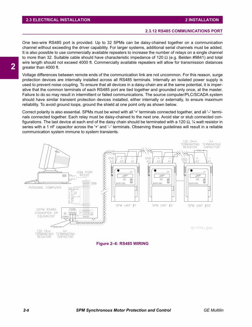
One two-wire RS485 port is provided. Up to 32 SPMs can be daisy-chained together on a communicationchannel without exceeding the driver capability. For larger systems, additional serial channels must be added.It is also possible to use commercially available repeaters to increase the number of relays on a single channelto more than 32. Suitable cable should have characteristic impedance of 120 Ω (e.g. Belden #9841) and totalwire length should not exceed 4000 ft. Commercially available repeaters will allow for transmission distancesgreater than 4000 ft.
Voltage differences between remote ends of the communication link are not uncommon. For this reason, surgeprotection devices are internally installed across all RS485 terminals. Internally an isolated power supply isused to prevent noise coupling. To ensure that all devices in a daisy-chain are at the same potential, it is imper-ative that the common terminals of each RS485 port are tied together and grounded only once, at the master.Failure to do so may result in intermittent or failed communications. The source computer/PLC/SCADA systemshould have similar transient protection devices installed, either internally or externally, to ensure maximumreliability. To avoid ground loops, ground the shield at one point only as shown below.
Correct polarity is also essential. SPMs must be wired with all '+' terminals connected together, and all '–' termi-nals connected together. Each relay must be daisy-chained to the next one. Avoid star or stub connected con-figurations. The last device at each end of the daisy chain should be terminated with a 120 Ω, ¼ watt resistor inseries with a 1 nF capacitor across the '+' and '–' terminals. Observing these guidelines will result in a reliablecommunication system immune to system transients.
Figure 2–6: RS485 WIRING
GE Multilin SPM Synchronous Motor Protection and Control 3-1
3 SYNCHRONOUS MOTOR APPLICATIONS 3.1 OVERVIEW
3
3 SYNCHRONOUS MOTOR APPLICATIONS 3.1 OVERVIEW 3.1.1 GENERAL
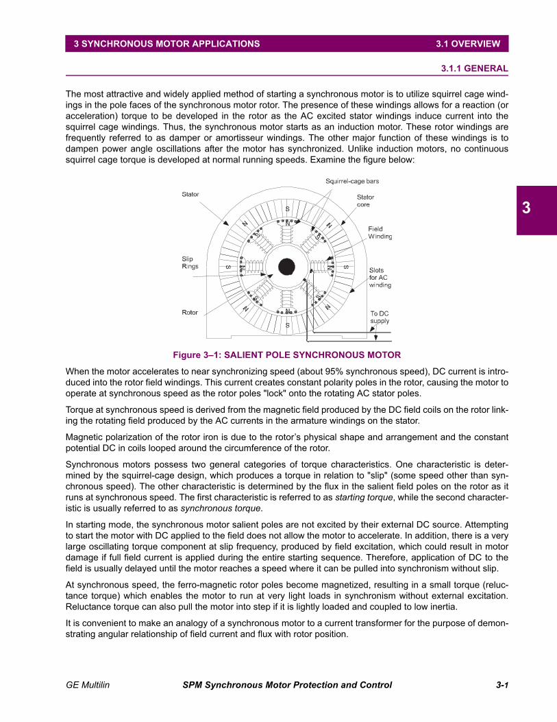
The most attractive and widely applied method of starting a synchronous motor is to utilize squirrel cage wind-ings in the pole faces of the synchronous motor rotor. The presence of these windings allows for a reaction (oracceleration) torque to be developed in the rotor as the AC excited stator windings induce current into thesquirrel cage windings. Thus, the synchronous motor starts as an induction motor. These rotor windings arefrequently referred to as damper or amortisseur windings. The other major function of these windings is todampen power angle oscillations after the motor has synchronized. Unlike induction motors, no continuoussquirrel cage torque is developed at normal running speeds. Examine the figure below:
Figure 3–1: SALIENT POLE SYNCHRONOUS MOTOR
When the motor accelerates to near synchronizing speed (about 95% synchronous speed), DC current is intro-duced into the rotor field windings. This current creates constant polarity poles in the rotor, causing the motor tooperate at synchronous speed as the rotor poles "lock" onto the rotating AC stator poles.
Torque at synchronous speed is derived from the magnetic field produced by the DC field coils on the rotor link-ing the rotating field produced by the AC currents in the armature windings on the stator.
Magnetic polarization of the rotor iron is due to the rotor’s physical shape and arrangement and the constantpotential DC in coils looped around the circumference of the rotor.
Synchronous motors possess two general categories of torque characteristics. One characteristic is deter-mined by the squirrel-cage design, which produces a torque in relation to "slip" (some speed other than syn-chronous speed). The other characteristic is determined by the flux in the salient field poles on the rotor as itruns at synchronous speed. The first characteristic is referred to as starting torque, while the second character-istic is usually referred to as synchronous torque.
In starting mode, the synchronous motor salient poles are not excited by their external DC source. Attemptingto start the motor with DC applied to the field does not allow the motor to accelerate. In addition, there is a verylarge oscillating torque component at slip frequency, produced by field excitation, which could result in motordamage if full field current is applied during the entire starting sequence. Therefore, application of DC to thefield is usually delayed until the motor reaches a speed where it can be pulled into synchronism without slip.
At synchronous speed, the ferro-magnetic rotor poles become magnetized, resulting in a small torque (reluc-tance torque) which enables the motor to run at very light loads in synchronism without external excitation.Reluctance torque can also pull the motor into step if it is lightly loaded and coupled to low inertia.
It is convenient to make an analogy of a synchronous motor to a current transformer for the purpose of demon-strating angular relationship of field current and flux with rotor position.
3-2 SPM Synchronous Motor Protection and Control GE Multilin
3.1 OVERVIEW 3 SYNCHRONOUS MOTOR APPLICATIONS
3
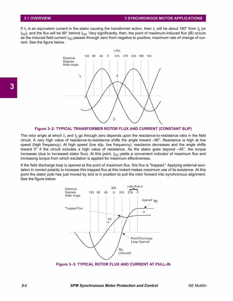
If I1 is an equivalent current in the stator causing the transformer action, then I1 will be about 180° from I2 (orIFD), and the flux will be 90° behind IFD. Very significantly, then, the point of maximum-induced flux (Ø) occursas the induced field current IFD passes through zero from negative to positive; maximum rate of change of cur-rent. See the figure below.
Figure 3–2: TYPICAL TRANSFORMER ROTOR FLUX AND CURRENT (CONSTANT SLIP)
The rotor angle at which I1 and I2 go through zero depends upon the reactance-to-resistance ratio in the fieldcircuit. A very high value of reactance-to-resistance shifts the angle toward –90°. Reactance is high at lowspeed (high frequency). At high speed (low slip, low frequency), reactance decreases and the angle shiftstoward 0° if the circuit includes a high value of resistance. As the stator goes beyond –45°, the torqueincreases (due to increased stator flux). At this point, IFD yields a convenient indicator of maximum flux andincreasing torque from which excitation is applied for maximum effectiveness.
If the field discharge loop is opened at the point of maximum flux, this flux is "trapped." Applying external exci-tation in correct polarity to increase this trapped flux at this instant makes maximum use of its existence. At thispoint the stator pole has just moved by and is in position to pull the rotor forward into synchronous alignment.See the figure below.
Figure 3–3: TYPICAL ROTOR FLUX AND CURRENT AT PULL-IN

GE Multilin SPM Synchronous Motor Protection and Control 3-3
3 SYNCHRONOUS MOTOR APPLICATIONS 3.1 OVERVIEW
3
Figure 3–4: ANGULAR DISPLACEMENT OF ROTOR
It has been established that salient-pole torque near synchronous speed is a function of both slip and field-dis-charge resistance. The combined effects of cage torque and salient pole torque for a typical motor are shownbelow. The effect of a higher value of discharge resistance on a medium-torque motor are shown in Figure 3–6: FIELD DISCHARGE RESISTANCE – MEDIUM STARTING TORQUE. Obviously, without salient-pole torquethe motor would cease to accelerate certain loads at some point on the speed axis.
Figure 3–5: MOTOR TORQUE VS. SPEED
The upper limit of the discharge resistance is governed by the other function of the resistor, which is reducingfield voltage to safe levels during starting. As the discharge resistance increases so does the induced voltage,and at some point this voltage would be damaging to insulation or other components in the field circuit. Solid-state excitation and control components in the field circuit have had the effect of making the discharge resis-tance and its voltage effect more significant. There is a greater sensitivity to field voltage tolerance levels withsolid-state components.
HIGH-STARTING-TORQUE MOTORMEDIUM-STARTING-TORQUE MOTOR
3-4 SPM Synchronous Motor Protection and Control GE Multilin
3.1 OVERVIEW 3 SYNCHRONOUS MOTOR APPLICATIONS
3
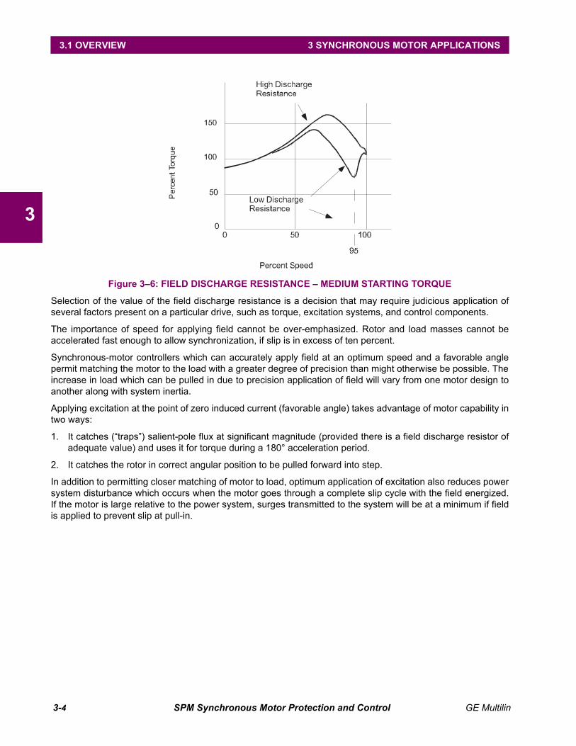
Figure 3–6: FIELD DISCHARGE RESISTANCE – MEDIUM STARTING TORQUE
Selection of the value of the field discharge resistance is a decision that may require judicious application ofseveral factors present on a particular drive, such as torque, excitation systems, and control components.
The importance of speed for applying field cannot be over-emphasized. Rotor and load masses cannot beaccelerated fast enough to allow synchronization, if slip is in excess of ten percent.
Synchronous-motor controllers which can accurately apply field at an optimum speed and a favorable anglepermit matching the motor to the load with a greater degree of precision than might otherwise be possible. Theincrease in load which can be pulled in due to precision application of field will vary from one motor design toanother along with system inertia.
Applying excitation at the point of zero induced current (favorable angle) takes advantage of motor capability intwo ways:
1. It catches (“traps”) salient-pole flux at significant magnitude (provided there is a field discharge resistor ofadequate value) and uses it for torque during a 180° acceleration period.
2. It catches the rotor in correct angular position to be pulled forward into step.
In addition to permitting closer matching of motor to load, optimum application of excitation also reduces powersystem disturbance which occurs when the motor goes through a complete slip cycle with the field energized.If the motor is large relative to the power system, surges transmitted to the system will be at a minimum if fieldis applied to prevent slip at pull-in.

GE Multilin SPM Synchronous Motor Protection and Control 3-5
3 SYNCHRONOUS MOTOR APPLICATIONS 3.2 COLLECTOR-RING MOTORS
3
3.2 COLLECTOR-RING MOTORS 3.2.1 STARTING AND SYNCHRONIZING
Control functions for starting the synchronous motor include the following:
• Applying power to the stator; at full voltage or reduced voltage.
• Shunting the field with a discharge resistor (FDRS).
• Sensing rotor speed.
• Sensing rotor angle.
• Applying excitation at optimum speed and angle.
• Reluctance torque synchronizing.
The first step in starting a synchronous motor is to apply power to the stator by means of a magnetic contactoror circuit breaker.
Shunting a resistor around the motor field during starting is accomplished with a field contactor. Optimum appli-cation of excitation (that is, closing the field contactor) requires accurate sensing of motor speed and rotorangle. This SPM provides this function. Optimum speed for pull-in varies with motor design and with the fielddischarge resistor value. Adjustment of the control to apply field at various values of motor speed is important.The correct rotor angle for field application does not vary and is always the point where induced field currentpasses through zero going from negative to positive – the point of maximum rotor flux (see Figure 3–3:: TYPI-CAL ROTOR FLUX AND CURRENT AT PULL-IN on page 3–2). Maximum utilization of motor pull-in capabilitydepends upon the degree to which the control can accurately sense speed and rotor angle.
Rotor frequency is the most positive electrical parameter available for indicating speed, and can be sensed bydetecting the frequency of the voltage across FDRS. Voltage across FDRS is not actually "induced field volt-age," but is the voltage which is essentially in time phase relation to the current through the resistor. That is,the current goes through zero at the same time the voltage goes through zero.
The SPM detects the proper rotor speed (PRS) and rotor angle (PRA) signal, implemented in the Field Pro-grammable Gate Array (FPGA). Outputs from the PRS and the circuits are used to determine the proper timeto close the Field Application Relay (FAR), based on the percent synchronous slip setpoint. When the properrotor speed and the proper rotor angle conditions are met as determined by the FPGA, the CPU delivers a sig-nal to the FAR Relay so it can close its contact FAR1-FAR2. FAR picks up field contactor FC to apply excitationto the motor field and to open the field discharge resistor loop. See Figure 2–4: PANEL AND TERMINAL LAY-OUT on page 2–5 for details. The speed at which the motor is to synchronize (PRS) can be programmed from90 to 99.5% of synchronous speed.

3-6 SPM Synchronous Motor Protection and Control GE Multilin
3.2 COLLECTOR-RING MOTORS 3 SYNCHRONOUS MOTOR APPLICATIONS
3
3.2.2 RELUCTANCE TORQUE SYNCHRONIZING
A lightly loaded synchronous motor connected to a low inertial load may pull into synchronism before the rotorpoles are externally magnetized. This is commonly known as reluctance torque synchronizing. This magnetiza-tion can result in sufficient torque to hold the salient poles in direct alignment with corresponding stator polesand run the motor at synchronous speed. However, when load is applied, the rotor begins to slip since thetorque developed is only a fraction of rated torque under separate excitation. Furthermore, the rotor is polar-ized by the stator flux under this condition and can therefore be polarized in any direct axis alignment; occur-ring each 180°. External excitation forces pole-to-pole alignment in only one orientation of the direct axis.
Should the rotor pull in to synchronism 180° away from the normal running alignment, external excitation willbuild up rotor flux in opposition to the stator flux. As the external excitation builds up, correct alignment of rotorto stator occurs by slipping one pole and the motor will then run in normal synchronism.
The Field Application Control must respond in such a way as to proceed with proper application of excitation inthe event the motor does synchronize on reluctance torque. The following diagram demonstrates how the SPMautomatically responds to reluctance torque synchronizing.
Figure 3–7: RELUCTANCE TORQUE MOTOR MAGNETIZATION
CORRECT
ORIENTATION
180°
DISORIENTATION
GE Multilin SPM Synchronous Motor Protection and Control 3-7
3 SYNCHRONOUS MOTOR APPLICATIONS 3.2 COLLECTOR-RING MOTORS
3
3.2.3 STARTING PROTECTION
The amortisseur, or cage winding of a synchronous motor, is probably the element most susceptible to thermaldamage. Its function is essentially operative only during starting, and there are limitations on space availablefor its construction onto the rotor. Hence, it is usually made of lighter material than the cage winding of aninduction motor. The cage is also vulnerable to overheating should the motor be allowed to run out of synchro-nism with no excitation. In this case, it runs as an induction motor at some value of slip which will produce cagecurrent that develops running torque. However, the cage of a synchronous motor is not designed for continu-ous operation. Therefore, an important protective function of the controller is to prevent overheating of the cagewinding both during starting and running out of synchronism.
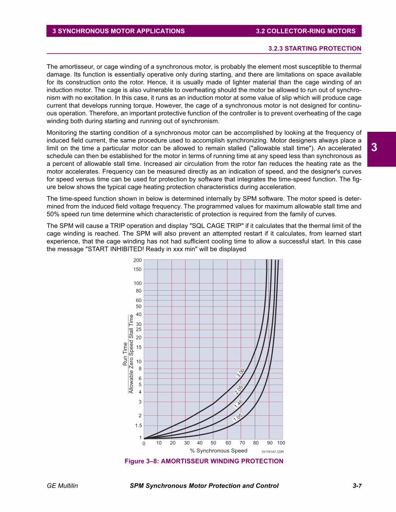
Monitoring the starting condition of a synchronous motor can be accomplished by looking at the frequency ofinduced field current, the same procedure used to accomplish synchronizing. Motor designers always place alimit on the time a particular motor can be allowed to remain stalled ("allowable stall time"). An acceleratedschedule can then be established for the motor in terms of running time at any speed less than synchronous asa percent of allowable stall time. Increased air circulation from the rotor fan reduces the heating rate as themotor accelerates. Frequency can be measured directly as an indication of speed, and the designer's curvesfor speed versus time can be used for protection by software that integrates the time-speed function. The fig-ure below shows the typical cage heating protection characteristics during acceleration.
The time-speed function shown in below is determined internally by SPM software. The motor speed is deter-mined from the induced field voltage frequency. The programmed values for maximum allowable stall time and50% speed run time determine which characteristic of protection is required from the family of curves.
The SPM will cause a TRIP operation and display "SQL CAGE TRIP" if it calculates that the thermal limit of thecage winding is reached. The SPM will also prevent an attempted restart if it calculates, from learned startexperience, that the cage winding has not had sufficient cooling time to allow a successful start. In this casethe message "START INHIBITED! Ready in xxx min" will be displayed
Figure 3–8: AMORTISSEUR WINDING PROTECTION
1
200
150
2
6
3
8
5
15
25
20
60
80
30
50
40
4
1.5
10
100
0
10 20 60 90 1008070504030
% Synchronous Speed 701761A7.CDR
Run
Tim
eA
llow
able
Zero
Speed
Sta
llT
ime
3.00
2.05
1.46
1.05
3-8 SPM Synchronous Motor Protection and Control GE Multilin
3.2 COLLECTOR-RING MOTORS 3 SYNCHRONOUS MOTOR APPLICATIONS
3
3.2.4 REDUCED VOLTAGE STARTING
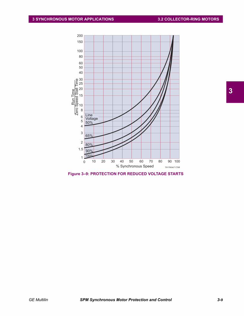
Many synchronous motor starting applications involve either reduced voltage (starting reactor or autotrans-former) or part-winding starting methods. When these methods are used, the available torque for accelerationis reduced from the torque that would result from a full-voltage start. Also, the allowable stall time of a motor isextended during a reduced-voltage start due to the reduced heating-rate resulting from lower inrush currents.
The SPM has the ability to take advantage of the motor's extended stall time so that the motor and load canaccelerate to synchronous speed in a time period longer than would be allowed with a full voltage start. Theacceleration torque is reduced as the square of the ratio of reduced voltage to full voltage, and the motor-heat-ing rate is proportional to the square of the starting current. Since the motor inrush current is reduced propor-tionally with the voltage reduction (due to the constant impedance of the synchronous motor at stall) thefollowing allowable stall time factor applies:
where: IPLR = programmed full voltage locked rotor current.IMLR = measured inrush current.
This ratio can be used as a factor for increasing the stall time above the full voltage allowable stall time for anygiven speed. See Figure 19.
The SPM calculates the ratio, squares it, and factors this value into the stall time algorithm approximately one-tenth of a second after motor starts. When the final step contactor closes and applies full voltage to the motorwindings, a N.O. interlock from this contactor is wired to the SPM to signal that the motor is now at full voltage.The correction factor for reduced voltage starts then immediately becomes unity.
If, for any reason, it is not desirable to have this ratio correction factored in, a jumper may be placed acrossinputs NX1 and NX2. Conversely, if the motor is started from a weak system, and significant voltage dips areexpected during starting, the factory jumper from NX1 to NX2 may be removed. The SPM will automaticallyextend the stall and accelerating time per the reduced voltage factor.
To find the protective characteristic used, plot the programmed value for 50% run time anddraw in the complete curve through the plotted point using the above curves as a guide.
The curves shown in the following diagram demonstrate how the trip characteristic of theamortisseur winding protection is adjusted for reduced voltage starts. For this example, curve1 is taken from one of the family of curves in Figure 3–8: AMORTISSEUR WINDING PROTEC-TION on page 3–7.
IPLRIMLR------------⎝ ⎠⎛ ⎞
2
NOTE
NOTE
GE Multilin SPM Synchronous Motor Protection and Control 3-9
3 SYNCHRONOUS MOTOR APPLICATIONS 3.2 COLLECTOR-RING MOTORS
3
Figure 3–9: PROTECTION FOR REDUCED VOLTAGE STARTS
1
200
150
2
6
3
8
5
15
25
20
60
80
30
50
40
4
1.5
10
100
0
10 20 60 90 1008070504030
% Synchronous Speed
65%
80%
90%
100%
701760A7.CDR
Run
Tim
eZ
ero
Speed
Sta
llT
ime
LineVoltage50%

3-10 SPM Synchronous Motor Protection and Control GE Multilin
3.2 COLLECTOR-RING MOTORS 3 SYNCHRONOUS MOTOR APPLICATIONS
3
3.2.5 POWER FACTOR (PULL-OUT) PROTECTION
Synchronous motors are designed to run at constant speed and drive shaft loads from torque derived from themagnetic poles on their rotors magnetically linking opposite stator poles. Whenever the rotor turns at a speedless than that of stator rotating field, the motor is said to be slipping poles. Slip can occur with the field polesmagnetized while running in synchronism from the following four major causes.
1. A gradual increase in load beyond the pull-out capabilities of the motor.
2. A slow decrease in field current.
3. A sudden large impact load.
4. A system fault or voltage dip lasting long enough to cause pull-out.
Loss of synchronism with field applied will create intense pulsations in torque at the motor shaft each time astator pole passes a rotor pole. Corresponding pulsations occur in line current. Both types of pulsations can bedamaging. Torque pulsations can break a shaft, coupling, or other mechanical elements, and current pulsa-tions can interfere with smooth power system operation. Slipping poles with field applied is always unaccept-able for a synchronous motor, therefore some means must be provided to prevent this condition fromoccurring.
One of the most reliable indicators of synchronous and asynchronous (out-of-step) operation is the motorpower factor. Power factor is related to the phase angle between voltage and current. Synchronous motors sel-dom, if ever, operate continuously at lagging power factor. Synchronous motors run at either unity or somevalue of leading power factor. Lagging power factor appears when the motor load angle increases beyondrated, becoming almost fully lagging (90°) as the motor slips out-of-step. Therefore, lagging power factor canbe utilized to initiate action to prevent slipping.
Torque and power pulsations during slip can be reduced by removing field current to the rotor poles. The motorwill then run essentially as an induction motor on its amortisseur winding. Slip with the field current removed istolerable to the load and power system but intolerable for any length of time to the motor amortisseur windingitself, since the winding is designed with limited thermal capability and for short-time operation. Motor PowerFactor during induction motor operation (that is with field removed) is always lagging. However, the degree towhich the current lags the voltage is less than at pull-out when field poles are excited. Lagging power factorcan again be utilized as an indicator of "slip" during induction motor operation.
For synchronous motors, power-factor monitoring can be employed to guard against pull-out or loss of fieldconditions.
GE Multilin SPM Synchronous Motor Protection and Control 3-11
3 SYNCHRONOUS MOTOR APPLICATIONS 3.2 COLLECTOR-RING MOTORS
3
3.2.6 POWER FACTOR OPERATION
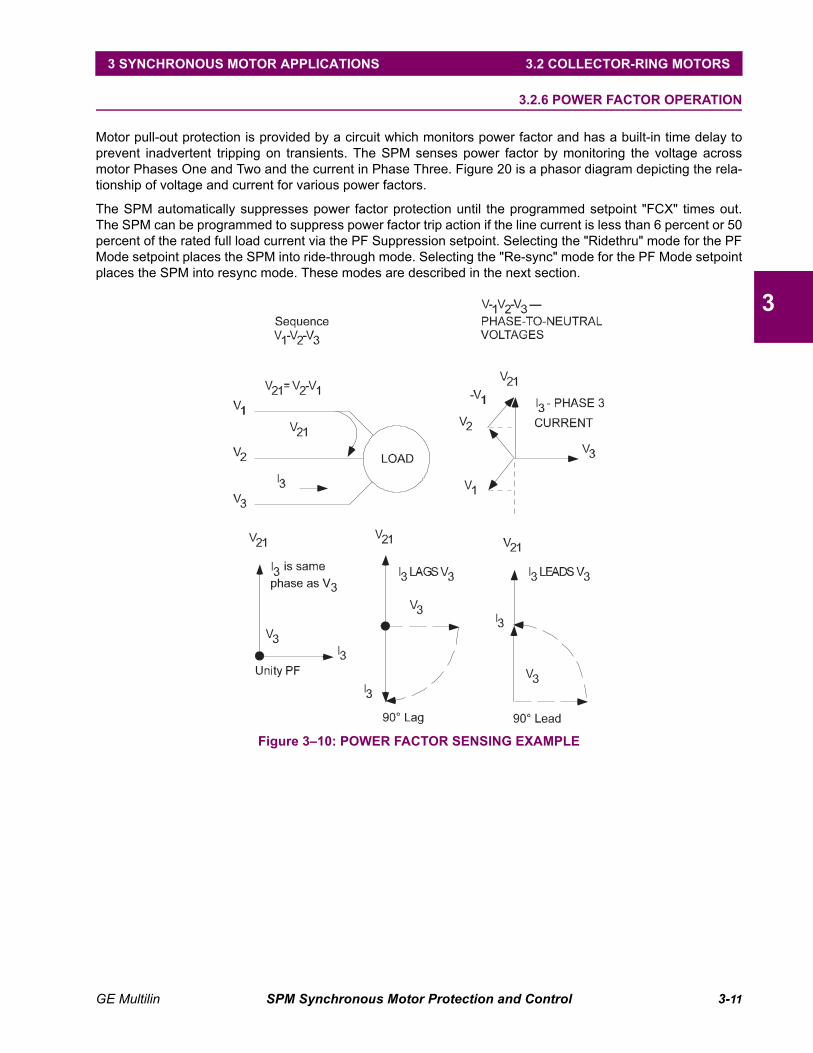
Motor pull-out protection is provided by a circuit which monitors power factor and has a built-in time delay toprevent inadvertent tripping on transients. The SPM senses power factor by monitoring the voltage acrossmotor Phases One and Two and the current in Phase Three. Figure 20 is a phasor diagram depicting the rela-tionship of voltage and current for various power factors.
The SPM automatically suppresses power factor protection until the programmed setpoint "FCX" times out.The SPM can be programmed to suppress power factor trip action if the line current is less than 6 percent or 50percent of the rated full load current via the PF Suppression setpoint. Selecting the "Ridethru" mode for the PFMode setpoint places the SPM into ride-through mode. Selecting the "Re-sync" mode for the PF Mode setpointplaces the SPM into resync mode. These modes are described in the next section.
Figure 3–10: POWER FACTOR SENSING EXAMPLE
3-12 SPM Synchronous Motor Protection and Control GE Multilin
3.2 COLLECTOR-RING MOTORS 3 SYNCHRONOUS MOTOR APPLICATIONS
3
3.2.7 CONTROLLER ACTION DURING PULL-OUT
If excessive mechanical load is applied to the motor shaft during normal running of the motor in synchronism,the resulting lagging power factor and/or line current surge will be detected by the SPM. Two forms of pull-outprotection are available. They are as follows
a) RESYNC MODE
Resync mode operation causes the Field Application Relay, FAR, to remove the motor-field excitation. Actionwill occur from either lagging power factor below the programmed setpoint or a line current surge aboveapproximately four times motor full-load current.
Relay FCX drops out at the same time as FAR. Load is removed if an automatic loader is connected.
The motor will continue to run with field removed for the programmed power factor delay time, and if resyn-chronization does not occur within this time, the TRIP relay will operate and the motor will stop.
The display will indicate "FAIL TO RESYNC!"
b) RIDE-THRU MODE
If the alternate "ride-thru" mode is selected, the field is not removed immediately as in the resync mode.
Instead, if the power factor dips below the trip point and persists for the PF time delay, the TRIP relay will oper-ate and the motor will stop. Also, a line current surge greater than approximately four times motor full load willcause TRIP operation if the PF time delay is exceeded. Power factor trips are indicated by "PWR FACTORTRIP!" in the display. Line current surges greater than four times rated line current are indicated by "PULL-OUT TRIP!".
GE Multilin SPM Synchronous Motor Protection and Control 3-13
3 SYNCHRONOUS MOTOR APPLICATIONS 3.2 COLLECTOR-RING MOTORS
3
3.2.8 EFFECT OF VOLTAGE DIPS ON MOTOR POWER FACTOR
Solid-state excitation systems have an effect on the way motor power factor responds to line voltage dips. Theeffect may be to cause a power-factor relay to operate inadvertently. This causes the motor to trip on laggingpower factor caused by a transient condition which is not an actual pull-out condition.
A solid-state exciter differs from a rotating exciter in the way it responds to voltage dips. The rotating inertia ofa Motor-Generator set may maintain excitation voltage relatively constant for several seconds, but a solid-stateexciter has practically no built-in delay in the way it responds to line voltage. Therefore, any delay in change ofmotor-rotor flux following an excitation voltage change is determined by the time constant of the rotor fieldpoles themselves. This is usually 0.5 to 1.0 seconds.
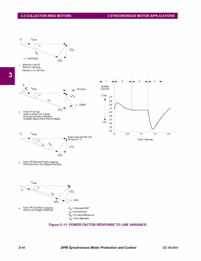
The sequence of events transpiring during a voltage dip with a solid-state exciter is shown in Figure 3–11:POWER FACTOR RESPONSE TO LINE VARIANCE on page 3–14.
Assuming the condition of a line voltage decrease of 15% with the motor initially at unity power factor, thepower factor will swing leading momentarily because the generated EMF does not change until the rotor fluxdecreases (determined by field time constant). The motor will tend to maintain constant horsepower by slightlyincreasing line current. As the field flux decreases, generated EMF also decreases, and the power factor willmove back towards unity, and there will be a load angle increase to permit motor torque to be restored to thatrequired to drive the load. During both of these sequences the motor power factor has not become significantlylagging, so the power-factor relay does not operate.
Finally, when line voltage comes back to normal, the power factor will momentarily swing over to lagging andthe power factor protection relay will trip because the rotor flux does not respond as rapidly to change as thestator. The generated EMF is low relative to line volts for a time period long enough to operate the relay.
A power-factor device with a 1.0 second built-in time delay should remain unaffected by these changes.
3-14 SPM Synchronous Motor Protection and Control GE Multilin
3.2 COLLECTOR-RING MOTORS 3 SYNCHRONOUS MOTOR APPLICATIONS
3
Figure 3–11: POWER FACTOR RESPONSE TO LINE VARIANCE

GE Multilin SPM Synchronous Motor Protection and Control 3-15
3 SYNCHRONOUS MOTOR APPLICATIONS 3.2 COLLECTOR-RING MOTORS
3
3.2.9 POWER FACTOR DETECTION & INDICATION – OVERHAULING LOAD
Many synchronous motor applications require that the motor operate with an overhauling load (in generatingmode). The power factor protection must be able to provide pull-out protection during overhauling load condi-tions.
The SPM provides pull-out protection for the synchronous motor operating in both the generating and themotoring mode. However, conventional power factor detection and indication for motors and generators areopposite. Simply, the convention is that a motor has a leading power factor when it is overexcited (producingreactive power). A generator, by convention, is leading power factor when it is underexcited (consuming reac-tive power). In order to understand this difference, it is necessary to recognize that the definition of a motorvoltage reference phasor is 180° displaced from its corresponding conventional generator voltage referencephasor.
Figure 3–12: POWER FACTOR SENSING – MOTOR MODE VS. GENERATOR MODE
Therefore, a given line current that leads the conventional generator voltage phasor will lag the correspondingconventional motor phasor. The diagram above shows that IA is lagging VAB (conventional motor phasor)while it is leading VBA (conventional generator phasor).
This confusion can be eliminated by defining one terminal voltage phasor for both generating and motoringmodes. Simply, if VAB is used as the reference phasor, then the leading power factor is always when the syn-chronous machine is producing reactive power and lagging power factor when it is consuming reactive power.
This is the approach that is taken with the PF display for the SPM. When the motor/generator is producingreactive kVA the sign of the power factor is displayed plus (+), indicating leading power factor, regardless of theoperating mode. When it is consuming reactive kVA the power factor is negative (–).
Therefore, whether the machine is motoring or generating, pull-out protection is provided by limiting the degreeof lagging power factor (under excitation) as detected by the SPM.
The power factor regulation option also performs to force the field in advance of a pull-out condition regardlessof whether the machine is operating as a motor or a generator.
3-16 SPM Synchronous Motor Protection and Control GE Multilin
3.2 COLLECTOR-RING MOTORS 3 SYNCHRONOUS MOTOR APPLICATIONS
3
3.2.10 POWER FACTOR REGULATION
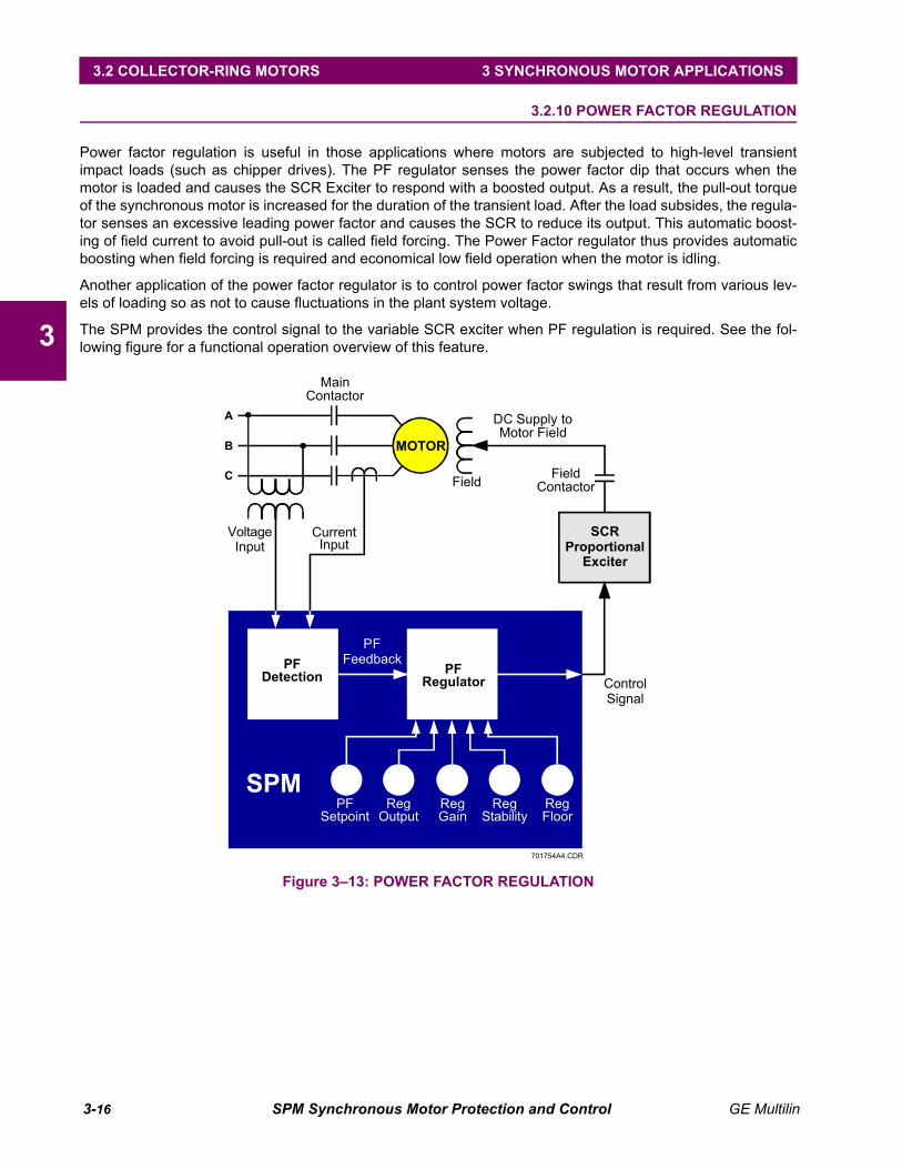
Power factor regulation is useful in those applications where motors are subjected to high-level transientimpact loads (such as chipper drives). The PF regulator senses the power factor dip that occurs when themotor is loaded and causes the SCR Exciter to respond with a boosted output. As a result, the pull-out torqueof the synchronous motor is increased for the duration of the transient load. After the load subsides, the regula-tor senses an excessive leading power factor and causes the SCR to reduce its output. This automatic boost-ing of field current to avoid pull-out is called field forcing. The Power Factor regulator thus provides automaticboosting when field forcing is required and economical low field operation when the motor is idling.
Another application of the power factor regulator is to control power factor swings that result from various lev-els of loading so as not to cause fluctuations in the plant system voltage.
The SPM provides the control signal to the variable SCR exciter when PF regulation is required. See the fol-lowing figure for a functional operation overview of this feature.
Figure 3–13: POWER FACTOR REGULATION
701754A4.CDR
A
B
C
MOTOR
PFDetection
VoltageInput
Field
DC Supply toMotor Field
PFSetpoint
RegOutput
RegGain
RegStability
RegFloor
CurrentInput
PFFeedback
ControlSignal
SCRProportionalExciter
SPM
FieldContactor
MainContactor
PFRegulator

GE Multilin SPM Synchronous Motor Protection and Control 3-17
3 SYNCHRONOUS MOTOR APPLICATIONS 3.3 BRUSHLESS CONTROLLER
3
3.3 BRUSHLESS CONTROLLER 3.3.1 DESCRIPTION
A brushless controller provides functions relevant to starting and protecting a brushless synchronous motor. Tounderstand the functional requirements, it is necessary to review the construction of a brushless motor.
3.3.2 BRUSHLESS MOTOR REVIEW
A brushless motor is like a conventional slip ring motor in that it has rotor-mounted field poles. These polesmust have DC supplied to their windings so they can "lock" onto the rotating stator field and run in synchro-nism. Also, like the slip-ring motor, amortisseur windings are built into the rotor pole tips to provide accelerationand damping torque during starting and normal operation. During start, the motor accelerates to near synchro-nous speed. When the rotor is close enough to synchronous speed for the field poles to pull the rotor into syn-chronism, DC is applied to the main field and the rotor pulls into step, normally operating at a power factorequal to or more leading than unity.
The brushless motor has, as its name implies, no brushes or slip-rings. Instead, it contains a rotating exciterwith stator mounted DC windings and the armature winding on the rotor. A rotor-mounted, solid-state rectifierconverts the AC from the exciter to DC for the main-field poles. The silicon controlled rectifiers (SCRs) andcontrol circuitry are rotor-mounted, along with the field discharge resistor, to control the application of DC to themain field at proper rotor speed and angle. The schematic below shows that the actual field control is providedwith the motor and is not part of the motor controller.
Figure 3–14: ROTATING RECTIFIER EXCITER WITH SYNCHRONOUS MOTOR

3-18 SPM Synchronous Motor Protection and Control GE Multilin
3.3 BRUSHLESS CONTROLLER 3 SYNCHRONOUS MOTOR APPLICATIONS
3
3.3.3 STARTING THE BRUSHLESS MOTOR
The brushless motor is started by first applying power to the stator windings then applying DC to the exciterfield. See Figure 2–3: TYPICAL WIRING DIAGRAM on page 2–4 for details. There are two basic timing func-tions a brushless controller must provide during start:
1. Apply DC to exciter (not main) field a given preset time after stator windings are energized.
2. Enable the power factor, pull-out protection, and provide a contact for signaling external automatic motorloading devices for motor loading. This is determined by a second given pre-set time delay that allows suf-ficient time after the application of the exciter field for the motor to synchronize and stabilize.
Both of these times can be entered as setpoint parameters in the SPM. (See programming, Section 4-9.)
Figure 3–15: BRUSHLESS STALL/ACCELERATION CHARACTERISTIC701762A5.CDR
2
200
150
3
7
4
8
9
6
15
300
30
500
20
400
70
900
80
1000
90
1500
40
600
60
800
50
700
5
10
100
2000
.8 .9 1 4 7 8 1065321.5
Trip Current(Multiples of Programmed Full Load Current)
Trip
Tim
e(s
econds)
A
B
C
A
B
C
Stall Time - 30 SecLocked Rotor - 6XFLC
Stall Time - 10 SecLocked Rotor - 6XFLC
Stall Time - 2 SecLocked Rotor - 6XFLC
GE Multilin SPM Synchronous Motor Protection and Control 3-19
3 SYNCHRONOUS MOTOR APPLICATIONS 3.3 BRUSHLESS CONTROLLER
3
3.3.4 STALL PROTECTION
Stall protection is derived from stator current inputs from two lines feeding the motor. The protection character-istic is shown in Figure 3–15: BRUSHLESS STALL/ACCELERATION CHARACTERISTIC on page 3–18. Afterthe motor synchronizes, the SPM monitors motor cool down approximately every 20 minutes rate to provideprotection against motor abuse from too-frequent starting. The SPM will indicate on the display the requiredwait time period that must be allowed before attempting a restart on a motor that has been shutdown from astall protective operation, or one in which two or more rapidly successive start/stop operations have been per-formed.
3.3.5 POWER FACTOR (PULL-OUT) PROTECTION
The power factor protection for brushless control operates as power factor protection for collector-ring motorsdescribed in Section 3.2.6. However, current I3 is derived internally to the SPM by algebraically summing cur-rents at the I1 and I2 inputs.
It is important to connect current inputs for I1 and I2 as shown in Figure 8 for brushlessmachines.
Only the ride-through mode is available for brushless machines. If an attempt to resynchronize isdesirable, set the "PF trip delay" parameter for one or two seconds. If the motor slips a pole in this
condition, the rotor-mounted, control device will remove the field instantaneously. When, and if, the motorrecovers from the disturbance, the main field will be applied. If it does not recover within the "PF trip time delay"the motor will trip.
If no attempt to resync is desirable, set the "PF trip time delay" parameter to 0.1 second. This time will be tooshort for the power factor to recover following a slipped pole condition and the motor will trip on lagging powerfactor.
3.3.6 POWER FACTOR REGULATION
Power factor regulation is not recommended on brushless machines due to instability problems arising fromthe long time constant of the rotating exciter field.
NOTE

3-20 SPM Synchronous Motor Protection and Control GE Multilin
3.3 BRUSHLESS CONTROLLER 3 SYNCHRONOUS MOTOR APPLICATIONS
3

GE Multilin SPM Synchronous Motor Protection and Control 4-1
4 USER INTERFACE 4.1 SPMPC SOFTWARE
4
4 USER INTERFACE 4.1 SPMPC SOFTWARE 4.1.1 DESCRIPTION
This chapter provides all the necessary information to install and/or upgrade a previous installation of theSPMPC software, and write/edit setpoint files.
The SPMPC software is only compatible with firmware versions 200 and higher.
The following sections are included in this chapter:
• System requirements
• SPMPC software version for previous installation check
• SPMPC software installation/upgrade procedure
• SPMPC software system configuration
• Creating/Editing/Upgrading/Downloading Setpoint Files
• Printing Setpoints and Actual Values
• Using Trending
The following minimum requirements must be met for the software to operate properly.
• Processor: minimum 486, Pentium recommended
• Memory: minimum 4 MB, 16 MB minimum recommended (540 K of conventional memory)
• Hard Drive: 20 MB free space required before installation of PC program.
• O/S: minimum Windows 3.1, Windows NT or Windows 95/98/2000 recommendedWindows 3.1 Users must ensure that SHARE.EXE is installed.
If a version of the SPMPC software is currently installed, note the path and directory name as this informationwill be needed when upgrading.
NOTE
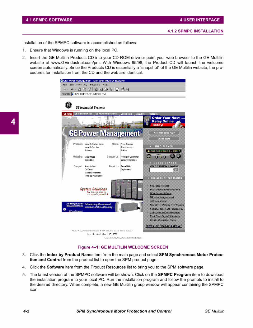
4-2 SPM Synchronous Motor Protection and Control GE Multilin
4.1 SPMPC SOFTWARE 4 USER INTERFACE
4
4.1.2 SPMPC INSTALLATION
Installation of the SPMPC software is accomplished as follows:
1. Ensure that Windows is running on the local PC.
2. Insert the GE Multilin Products CD into your CD-ROM drive or point your web browser to the GE Multilinwebsite at www.GEindustrial.com/pm. With Windows 95/98, the Product CD will launch the welcomescreen automatically. Since the Products CD is essentially a “snapshot” of the GE Multilin website, the pro-cedures for installation from the CD and the web are identical.
Figure 4–1: GE MULTILIN WELCOME SCREEN
3. Click the Index by Product Name item from the main page and select SPM Synchronous Motor Protec-tion and Control from the product list to open the SPM product page.
4. Click the Software item from the Product Resources list to bring you to the SPM software page.
5. The latest version of the SPMPC software will be shown. Click on the SPMPC Program item to downloadthe installation program to your local PC. Run the installation program and follow the prompts to install tothe desired directory. When complete, a new GE Multilin group window will appear containing the SPMPCicon.
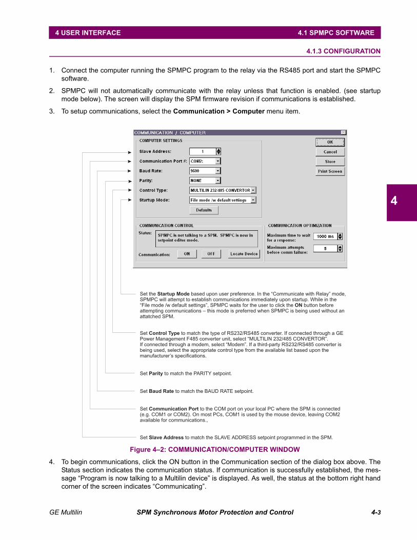
GE Multilin SPM Synchronous Motor Protection and Control 4-3
4 USER INTERFACE 4.1 SPMPC SOFTWARE
4
4.1.3 CONFIGURATION
1. Connect the computer running the SPMPC program to the relay via the RS485 port and start the SPMPCsoftware.
2. SPMPC will not automatically communicate with the relay unless that function is enabled. (see startupmode below). The screen will display the SPM firmware revision if communications is established.
3. To setup communications, select the Communication > Computer menu item.
Figure 4–2: COMMUNICATION/COMPUTER WINDOW
4. To begin communications, click the ON button in the Communication section of the dialog box above. TheStatus section indicates the communication status. If communication is successfully established, the mes-sage “Program is now talking to a Multilin device” is displayed. As well, the status at the bottom right handcorner of the screen indicates “Communicating”.
Set the based upon user preference. In the “Communicate with Relay” mode,SPMPC will attempt to establish communications immediately upon startup. While in the“File mode /w default settings”, SPMPC waits for the user to click the button beforeattempting communications – this mode is preferred when SPMPC is being used without anattatched SPM.
Startup Mode
ON
Set to match the type of RS232/RS485 converter. If connected through a GEPower Management F485 converter unit, select “MULTILIN 232/485 CONVERTOR”.If connected through a modem, select “Modem”. If a third-party RS232/RS485 converter isbeing used, select the appropriate control type from the available list based upon themanufacturer’s specifications.
Control Type
Set to match the PARITY setpoint.Parity
Set to match the BAUD RATE setpoint.Baud Rate
Set to the COM port on your local PC where the SPM is connected(e.g. COM1 or COM2). On most PCs, COM1 is used by the mouse device, leaving COM2available for communications.,
Communication Port
Set to match the SLAVE ADDRESS setpoint programmed in the SPM.Slave Address
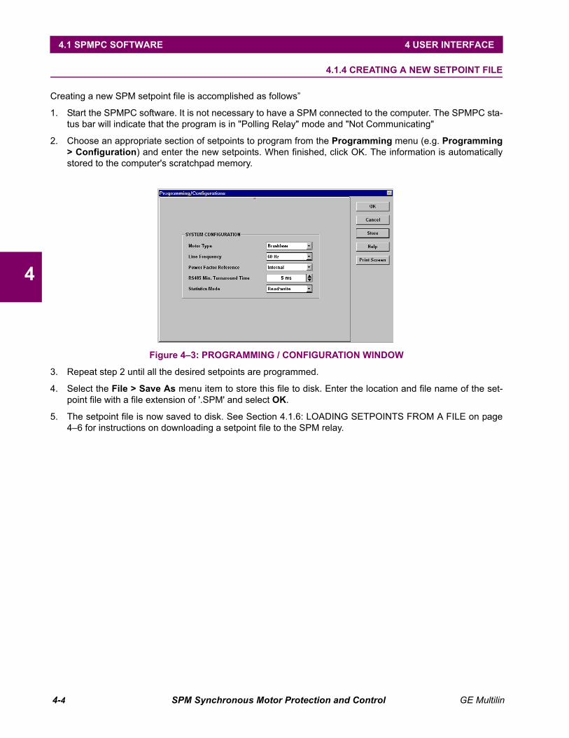
4-4 SPM Synchronous Motor Protection and Control GE Multilin
4.1 SPMPC SOFTWARE 4 USER INTERFACE
4
4.1.4 CREATING A NEW SETPOINT FILE
Creating a new SPM setpoint file is accomplished as follows”
1. Start the SPMPC software. It is not necessary to have a SPM connected to the computer. The SPMPC sta-tus bar will indicate that the program is in "Polling Relay" mode and "Not Communicating"
2. Choose an appropriate section of setpoints to program from the Programming menu (e.g. Programming> Configuration) and enter the new setpoints. When finished, click OK. The information is automaticallystored to the computer's scratchpad memory.
Figure 4–3: PROGRAMMING / CONFIGURATION WINDOW
3. Repeat step 2 until all the desired setpoints are programmed.
4. Select the File > Save As menu item to store this file to disk. Enter the location and file name of the set-point file with a file extension of '.SPM' and select OK.
5. The setpoint file is now saved to disk. See Section 4.1.6: LOADING SETPOINTS FROM A FILE on page4–6 for instructions on downloading a setpoint file to the SPM relay.
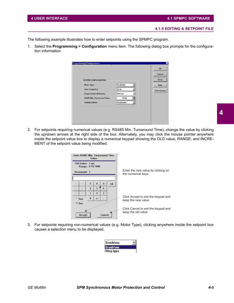
GE Multilin SPM Synchronous Motor Protection and Control 4-5
4 USER INTERFACE 4.1 SPMPC SOFTWARE
4
4.1.5 EDITING A SETPOINT FILE
The following example illustrates how to enter setpoints using the SPMPC program.
1. Select the Programming > Configuration menu item. The following dialog box prompts for the configura-tion information.
2. For setpoints requiring numerical values (e.g. RS485 Min. Turnaround Time), change the value by clickingthe up/down arrows at the right side of the box. Alternately, you may click the mouse pointer anywhereinside the setpoint value box to display a numerical keypad showing the OLD value, RANGE, and INCRE-MENT of the setpoint value being modified.
3. For setpoints requiring non-numerical values (e.g. Motor Type), clicking anywhere inside the setpoint boxcauses a selection menu to be displayed.
Enter the new value by clicking onthe numerical keys
Click Accept to exit the keypad andkeep the new value
Click Cancel to exit the keypad andkeep the old value
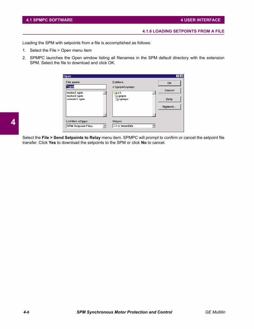
4-6 SPM Synchronous Motor Protection and Control GE Multilin
4.1 SPMPC SOFTWARE 4 USER INTERFACE
4
4.1.6 LOADING SETPOINTS FROM A FILE
Loading the SPM with setpoints from a file is accomplished as follows:
1. Select the File > Open menu item
2. SPMPC launches the Open window listing all filenames in the SPM default directory with the extensionSPM. Select the file to download and click OK.
Select the File > Send Setpoints to Relay menu item. SPMPC will prompt to confirm or cancel the setpoint filetransfer. Click Yes to download the setpoints to the SPM or click No to cancel.

GE Multilin SPM Synchronous Motor Protection and Control 4-7
4 USER INTERFACE 4.1 SPMPC SOFTWARE
4
4.1.7 UPGRADING SETPOINT FILES TO A NEW REVISION
It may be necessary to upgrade the revision code for a previously saved setpoint file when the SPM firmware isupgraded.
1. To upgrade the revision of a previously saved setpoint file, run SPMPC and establish communications withthe SPM through the RS485 connector.
2. Select the Actual Values > Product Information menu item and record the Main Software number of there-lay's firmware, e.g. 201.
3. Next, select the File > Open menu item and enter the location and filename of the setpoint File to bedownloaded to the connected relay. When the file is open, SPMPC will be in "Editing File" mode and "Notcommunicating".
4. Select the File > Properties menu item and note the version code of the setpoint file. If the Main Softwarenumber of the setpoint file (e.g. 20x) is different than the Main Software number of the firmware (noted inStep 2 as 201), use the pull-down tab to select the revision code that matches the firmware and click OK.
5. Select the File > Save menu item to save the setpoint file.
See the previous section for instructions on loading this setpoint file to the SPM relay.
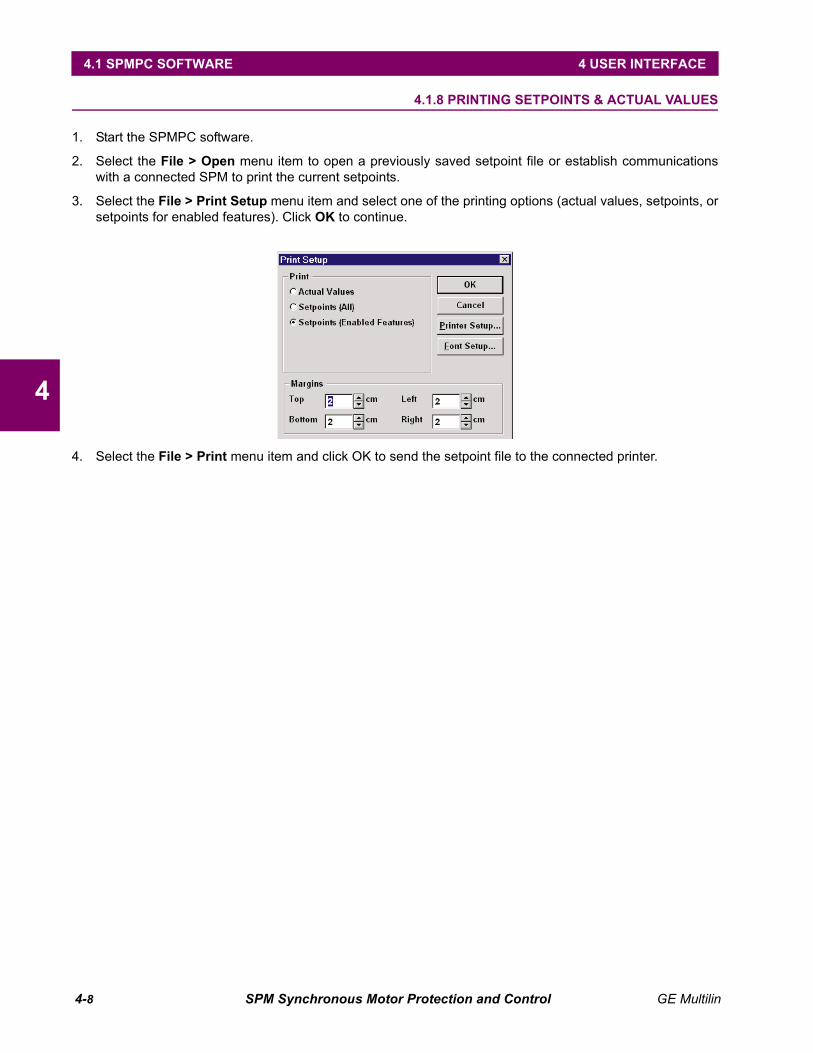
4-8 SPM Synchronous Motor Protection and Control GE Multilin
4.1 SPMPC SOFTWARE 4 USER INTERFACE
4
4.1.8 PRINTING SETPOINTS & ACTUAL VALUES
1. Start the SPMPC software.
2. Select the File > Open menu item to open a previously saved setpoint file or establish communicationswith a connected SPM to print the current setpoints.
3. Select the File > Print Setup menu item and select one of the printing options (actual values, setpoints, orsetpoints for enabled features). Click OK to continue.
4. Select the File > Print menu item and click OK to send the setpoint file to the connected printer.
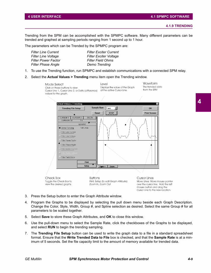
GE Multilin SPM Synchronous Motor Protection and Control 4-9
4 USER INTERFACE 4.1 SPMPC SOFTWARE
4
4.1.9 TRENDING
Trending from the SPM can be accomplished with the SPMPC software. Many different parameters can betrended and graphed at sampling periods ranging from 1 second up to 1 hour.
The parameters which can be Trended by the SPMPC program are:
Filter Line Current Filter Exciter CurrentFilter Line Voltage Filter Exciter VoltageFilter Power Factor Filter Field OhmsFilter Phase Angle Demo Trending
1. To use the Trending function, run SPMPC and establish communications with a connected SPM relay.
2. Select the Actual Values > Trending menu item open the Trending window.
3. Press the Setup button to enter the Graph Attribute window.
4. Program the Graphs to be displayed by selecting the pull down menu beside each Graph Description.Change the Color, Style, Width, Group #, and Spline selection as desired. Select the same Group # for allparameters to be scaled together.
5. Select Save to store these Graph Attributes, and OK to close this window.
6. Use the pull-down menu to select the Sample Rate, click the checkboxes of the Graphs to be displayed,and select RUN to begin the trending sampling.
7. The Trending File Setup button can be used to write the graph data to a file in a standard spreadsheetformat. Ensure that the Write Trended Data to File box is checked, and that the Sample Rate is at a min-imum of 5 seconds. Set the file capacity limit to the amount of memory available for trended data.
4-10 SPM Synchronous Motor Protection and Control GE Multilin
4.2 KEYPAD INTERFACE 4 USER INTERFACE
4
4.2 KEYPAD INTERFACE 4.2.1 DESCRIPTION
The SPM is a user programmable device with a wide range of setpoints, configurations, and calibration valuesthat enable operation with a wide variety of ring-type and brushless synchronous motors. This section dealswith programming the SPM for a ring-type motor. The setpoints will be explained and a practical example willbe given. The example may be followed step by step by the operator as a guide to program the SPM for theirmotor.
• GE Key. This key is used to enter or exit the different modes of the SPM (STAT MODE, PROGRAMMINGMODE, and TEST MODE). It is also used to cancel an operation, such as changing a setpoint.
• SCROLL Keys. These keys are used to scroll through the various menus, setpoints, configuration param-eters, etc. When the motor is in running mode, pressing either of these keys will halt the display from scroll-ing. They can then be used to step through the displayed values one at a time. Pressing and holding thiskey will resume the automatic scrolling of the display.
When changing a setpoint or other parameter, pressing and holding either of the SCROLL keys down willput the values being changed into a decade incremental scroll. Thus, changing a setpoint from 1 to 1000,the value would start to increment by the decade value (10, 100, or 1000) after every decade (after reach-ing 10, it increments by 10, after reaching 100, it increments by 100).
• ENTER Key. This key is used to make a selection or acts as an enter key, as prompted by the menu on thedisplay. This key must be pressed when setpoints, configuration parameters or calibration values areselected to be changed. It must also be pressed to save such changes.
The SPM has a "smart" parameter menu for setpoints that does not allow the user to enter values outsideof the valid range and automatically checks for setpoint dependencies.
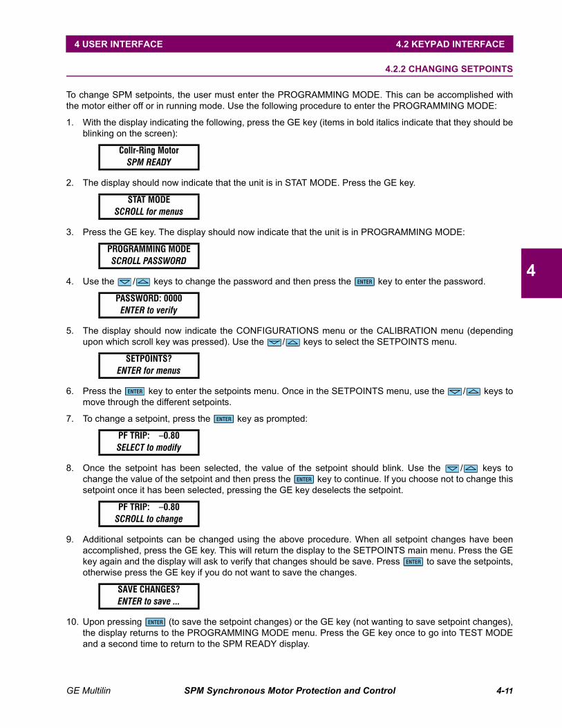
GE Multilin SPM Synchronous Motor Protection and Control 4-11
4 USER INTERFACE 4.2 KEYPAD INTERFACE
4
4.2.2 CHANGING SETPOINTS
To change SPM setpoints, the user must enter the PROGRAMMING MODE. This can be accomplished withthe motor either off or in running mode. Use the following procedure to enter the PROGRAMMING MODE:
1. With the display indicating the following, press the GE key (items in bold italics indicate that they should beblinking on the screen):
2. The display should now indicate that the unit is in STAT MODE. Press the GE key.
3. Press the GE key. The display should now indicate that the unit is in PROGRAMMING MODE:
4. Use the / keys to change the password and then press the key to enter the password.
5. The display should now indicate the CONFIGURATIONS menu or the CALIBRATION menu (dependingupon which scroll key was pressed). Use the / keys to select the SETPOINTS menu.
6. Press the key to enter the setpoints menu. Once in the SETPOINTS menu, use the / keys tomove through the different setpoints.
7. To change a setpoint, press the key as prompted:
8. Once the setpoint has been selected, the value of the setpoint should blink. Use the / keys tochange the value of the setpoint and then press the key to continue. If you choose not to change thissetpoint once it has been selected, pressing the GE key deselects the setpoint.
9. Additional setpoints can be changed using the above procedure. When all setpoint changes have beenaccomplished, press the GE key. This will return the display to the SETPOINTS main menu. Press the GEkey again and the display will ask to verify that changes should be save. Press to save the setpoints,otherwise press the GE key if you do not want to save the changes.
10. Upon pressing (to save the setpoint changes) or the GE key (not wanting to save setpoint changes),the display returns to the PROGRAMMING MODE menu. Press the GE key once to go into TEST MODEand a second time to return to the SPM READY display.
Collr-Ring MotorSPM READY
STAT MODESCROLL for menus
PROGRAMMING MODESCROLL PASSWORD
PASSWORD: 0000ENTER to verify
SETPOINTS?ENTER for menus
PF TRIP: –0.80SELECT to modify
PF TRIP: –0.80SCROLL to change
SAVE CHANGES?ENTER to save ...
ENTER
ENTER
ENTER
ENTER
ENTER
ENTER
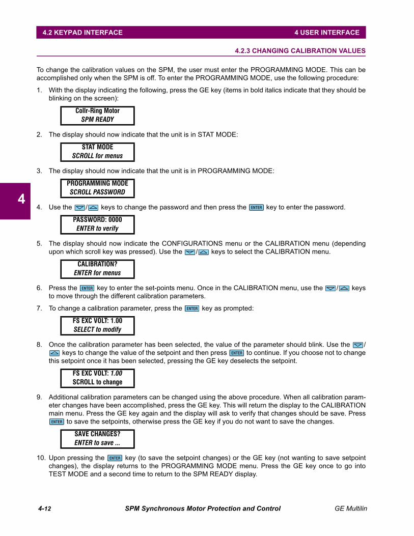
4-12 SPM Synchronous Motor Protection and Control GE Multilin
4.2 KEYPAD INTERFACE 4 USER INTERFACE
4
4.2.3 CHANGING CALIBRATION VALUES
To change the calibration values on the SPM, the user must enter the PROGRAMMING MODE. This can beaccomplished only when the SPM is off. To enter the PROGRAMMING MODE, use the following procedure:
1. With the display indicating the following, press the GE key (items in bold italics indicate that they should beblinking on the screen):
2. The display should now indicate that the unit is in STAT MODE:
3. The display should now indicate that the unit is in PROGRAMMING MODE:
4. Use the / keys to change the password and then press the key to enter the password.
5. The display should now indicate the CONFIGURATIONS menu or the CALIBRATION menu (dependingupon which scroll key was pressed). Use the / keys to select the CALIBRATION menu.
6. Press the key to enter the set-points menu. Once in the CALIBRATION menu, use the / keysto move through the different calibration parameters.
7. To change a calibration parameter, press the key as prompted:
8. Once the calibration parameter has been selected, the value of the parameter should blink. Use the / keys to change the value of the setpoint and then press to continue. If you choose not to change
this setpoint once it has been selected, pressing the GE key deselects the setpoint.
9. Additional calibration parameters can be changed using the above procedure. When all calibration param-eter changes have been accomplished, press the GE key. This will return the display to the CALIBRATIONmain menu. Press the GE key again and the display will ask to verify that changes should be save. Press
to save the setpoints, otherwise press the GE key if you do not want to save the changes.
10. Upon pressing the key (to save the setpoint changes) or the GE key (not wanting to save setpointchanges), the display returns to the PROGRAMMING MODE menu. Press the GE key once to go intoTEST MODE and a second time to return to the SPM READY display.
Collr-Ring MotorSPM READY
STAT MODESCROLL for menus
PROGRAMMING MODESCROLL PASSWORD
PASSWORD: 0000ENTER to verify
CALIBRATION?ENTER for menus
FS EXC VOLT: 1.00SELECT to modify
FS EXC VOLT: 1.00SCROLL to change
SAVE CHANGES?ENTER to save ...
ENTER
ENTER
ENTER
ENTER
ENTER
ENTER

GE Multilin SPM Synchronous Motor Protection and Control 4-13
4 USER INTERFACE 4.2 KEYPAD INTERFACE
4
4.2.4 CHANGING CONFIGURATIONS
To change the SPM configuration, the user must enter the PROGRAMMING MODE. This can be accomplishedwith the motor either off or in the running mode. To enter the PROGRAMMING MODE, the following proceduremust be used:
1. With the display indicating the following, press the GE key (items in bold italics indicate that they should beblinking on the screen):
2. The display should now indicate that the unit is in STAT MODE:
3. Press the GE key. The display should now indicate that the unit is in PROGRAMMING MODE:
4. Use the / keys to change the password and press to enter the password.
5. The display should now indicate the CONFIGURATIONS menu or the CALIBRATION menu (dependingupon which scroll key was pressed). Use the / keys to select the CONFIGURATIONS menu.
6. Press the key to enter the setpoints menu. Once in the CONFIGURATIONS menu, use the /keys to move through the different setpoints.
7. To change a configuration, press the key as prompted:
8. Once the configuration has been selected, the value of the setpoint should blink. Use the / keys tochange the value of the configuration and then press the key to continue. If you choose not tochange this setpoint once it has been selected, pressing the GE key deselects the setpoint.
9. Additional configurations can be changed using the above procedure. When all setpoint changes havebeen accomplished, press the GE Key. This will return the display to the CONFIGURATIONS main menu.Press the GE key again and the display will ask to verify that changes should be save. Press to savethe configurations, otherwise press the GE key if you do not want to save the changes.
10. Upon pressing the key (to save the setpoint changes) or the GE key (not wanting to save setpointchanges), the display returns to the PROGRAMMING MODE menu. Press the GE key once to go intoTEST MODE and a second time to return to the SPM READY display.
Collr-Ring MotorSPM READY
STAT MODESCROLL for menus
PROGRAMMING MODESCROLL PASSWORD
PASSWORD: 0000ENTER to verify
CONFIGURATIONS?ENTER for menus
MOTOR: Collr-RingSELECT to modify
MOTOR: Collr-RingSCROLL TO CHANGE
SAVE CHANGES?ENTER to save ...
ENTER
ENTER
ENTER
ENTER
ENTER
ENTER

4-14 SPM Synchronous Motor Protection and Control GE Multilin
4.2 KEYPAD INTERFACE 4 USER INTERFACE
4
4.2.5 VIEWING & CHANGING STATUS MODE PARAMETERS
To view or change the SPM status information, the user must enter the STAT MODE. This can be accom-plished with the motor either off or in running mode. Use the following procedure to enter the STAT MODE:
1. With the display indicating the following, press the GE key (items in bold italics indicate that they should beblinking on the screen):
2. The display should now indicate that the unit is in STAT MODE:
3. Use the / keys to scroll through the STAT MODE parameters.
4. If the SPM is configured such that status mode parameters are "read only", then these values can only beviewed and cannot be changed. If the SPM is configured such that status mode parameters are "read/write", then these values can be changed as follows.
5. Once the parameter that is to be changed is displayed on the display, press to select the parameter:
6. Use the / keys to change the values of the selected parameter and then press the key to con-tinue. If you choose not to change the parameter once it has been selected, pressing the GE key deselectsthe parameter.
7. Additional parameters can be changed using the above procedure. When all parameter changes havebeen accomplished, press the GE Key. This will return the display to the STAT MODE main menu. Pressthe GE key again and the display will change to the PROGRAMMING MODE main menu. Pressing the GEkey again puts the display into the TEST MODE main menu. Pressing the GE key gain will then return thedisplay to the SPM READY display.
4.2.6 ALTERNATE MENU OPERATION
In order to view setpoints without changing values, or to view setpoints if the password is unknown, the alter-nate menu can be used. When the SPM is in the ready mode,
press the key and the SPM will automatically switch into the alternate menu. The SPM will begin to auto-matically scroll through the setpoints. Pressing either of the / keys once will halt the display. Pressingeither of the / keys repeatedly will allow the user to scroll through the setpoints manually. This allowsthe user to scroll through the setpoints using the / keys but does not allow setpoints to be changed. Toreturn to the SPM READY display, press the key.
Collr-Ring MotorSPM READY
STAT MODESCROLL for menus
MOTOR HRS: 0SELECT to modify
MOTOR HRS: 0SCROLL to change
Collr-Ring MotorSPM READY
ENTER
ENTER
ENTER
ENTER
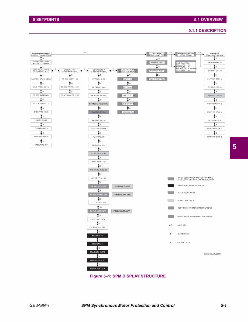
GE Multilin SPM Synchronous Motor Protection and Control 5-1
5 SETPOINTS 5.1 OVERVIEW
5
5 SETPOINTS 5.1 OVERVIEW 5.1.1 DESCRIPTION
Figure 5–1: SPM DISPLAY STRUCTURE

5-2 SPM Synchronous Motor Protection and Control GE Multilin
5.2 SETPOINTS MENU 5 SETPOINTS
5
5.2 SETPOINTS MENU 5.2.1 POWER FACTOR TRIP
FUNCTION:
The PF TRIP setpoint represents the value of lagging power factor that causes a trip or resynchronizing attemptduring motor operation. For example, if the trip power factor is set at 0.85 lagging (–0.85), the SPM trips if thepower factor falls below 0.85 for a time longer than the PF DELAY setpoint.
MOTOR TYPE:
Collector-Ring and Brushless
NOTE:
The SPM automatically suppresses the power factor trip element until the programmed FCX DELAY times out.
5.2.2 POWER FACTOR DELAY
FUNCTION:
The PF DELAY setpoint represents the elapsed time delay after the power factor dips below the PF TRIP setpoint(or after the line current remains greater than four times the FL AMPS setpoint) before the SPM initiates trippingaction for power factor trip (or pull-out trip).
MOTOR TYPE:
Collector-Ring and Brushless
5.2.3 POWER FACTOR SUPRESSION
FUNCTION:
Power factor suppression is used to inhibit PF TRIP or PULL-OUT trip action when the line current is less thanthe setpoint percentage of the full-load current (FL AMPS) setpoint.
MOTOR TYPE:
Collector-Ring and Brushless
PF TRIP: –0.60ENTER to modify
Range: –0.60 to 1.00Step: 0.01
PF DELAY: 1.0 sENTER to modify
Range: 0.1 to 10.0 secondsStep: 0.1
PF SUPP: 6% FLCENTER to modify
Range: 6%, 50% FLC

GE Multilin SPM Synchronous Motor Protection and Control 5-3
5 SETPOINTS 5.2 SETPOINTS MENU
5
5.2.4 POWER FACTOR MODE
FUNCTION:
Ridethru Mode: This mode allows the motor to "ride through" power factor dips of less duration than the PFDELAY but will protect against cyclical power factor dips. Brushless motors are automatically in ridethru mode.
Resync Mode: Upon measuring a power factor below the PF TRIP setpoint, the unit de-energizes the FAR andFCX relays and attempts to resynchronize the motor. The motor continues to run with the field removed for theprogrammed PF DELAY, and if resynchronization does not occur within this time a PWR FACTOR TRIP occurs,operating the trip relay and stopping the motor.
MOTOR TYPE:
Collector-Ring
5.2.5 FIELD APPLICATION RELAY DELAY
FUNCTION:
This setpoint provides for a time delay in closing the field application relay (FAR) to apply DC to the exciterafter the stator windings are energized.
MOTOR TYPE:
Brushless
5.2.6 FIELD CONTACTOR AUXILIARY RELAY DELAY
FUNCTION:
Program FCX DELAY time to enable power factor protection, field overtemperature protection, field loss protec-tion and auto-loading FCX relay operation. Timing begins with FAR relay operation.
MOTOR TYPE:
Collector-Ring and Brushless
PF MODE: ridethruENTER to modify
Range: ridethru, resync
FAR DELAY: 0 sENTER to modify
Range: 0 to 90 secondsStep: 1
FCX DELAY: 1 sENTER to modify
Range: 1 to 6 seconds for Collector-Ring1 to 90 seconds for Brushless
Step: 1
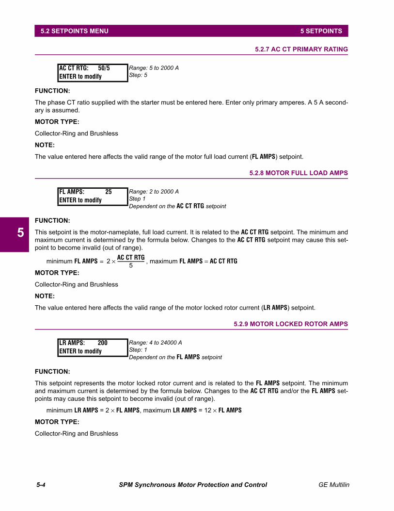
5-4 SPM Synchronous Motor Protection and Control GE Multilin
5.2 SETPOINTS MENU 5 SETPOINTS
5
5.2.7 AC CT PRIMARY RATING
FUNCTION:
The phase CT ratio supplied with the starter must be entered here. Enter only primary amperes. A 5 A second-ary is assumed.
MOTOR TYPE:
Collector-Ring and Brushless
NOTE:
The value entered here affects the valid range of the motor full load current (FL AMPS) setpoint.
5.2.8 MOTOR FULL LOAD AMPS
FUNCTION:
This setpoint is the motor-nameplate, full load current. It is related to the AC CT RTG setpoint. The minimum andmaximum current is determined by the formula below. Changes to the AC CT RTG setpoint may cause this set-point to become invalid (out of range).
minimum FL AMPS , maximum FL AMPS = AC CT RTG
MOTOR TYPE:
Collector-Ring and Brushless
NOTE:
The value entered here affects the valid range of the motor locked rotor current (LR AMPS) setpoint.
5.2.9 MOTOR LOCKED ROTOR AMPS
FUNCTION:
This setpoint represents the motor locked rotor current and is related to the FL AMPS setpoint. The minimumand maximum current is determined by the formula below. Changes to the AC CT RTG and/or the FL AMPS set-points may cause this setpoint to become invalid (out of range).
minimum LR AMPS = 2 × FL AMPS, maximum LR AMPS = 12 × FL AMPS
MOTOR TYPE:
Collector-Ring and Brushless
AC CT RTG: 50/5ENTER to modify
Range: 5 to 2000 AStep: 5
FL AMPS: 25ENTER to modify
Range: 2 to 2000 AStep 1Dependent on the AC CT RTG setpoint
LR AMPS: 200ENTER to modify
Range: 4 to 24000 AStep: 1Dependent on the FL AMPS setpoint
2 AC CT RTG5
-------------------------×=

GE Multilin SPM Synchronous Motor Protection and Control 5-5
5 SETPOINTS 5.2 SETPOINTS MENU
5
5.2.10 SYNCHRONOUS SLIP
FUNCTION:
The value stored here is the slip at which the SPM will close the field contactor (FAR). It is expressed as per-cent slip.
MOTOR TYPE:
Collector-Ring
EXAMPLE:
To close the field contactor (apply the field) when the motor reaches 94.5% of synchronous speed, the SYNCSLIP setpoint is determined as follows:
100% speed – 94.5% speed = 5.5% sync slip
5.2.11 STALL TIME
FUNCTION:
This setpoint determines the allowable time that power may be applied to the motor during locked rotor condi-tions. This information may normally be found on the motor control data sheet available from the motor manu-facturer.
MOTOR TYPE:
Collector-Ring and Brushless
5.2.12 RUN TIME
FUNCTION:
Run time is the time that the motor may run at 50% speed and is expressed as a multiple of the allowablemotor stall time.
MOTOR TYPE:
Collector-Ring
EXAMPLE:
If the motor stall time is 10 seconds and RUN TIME is set to 3.00, then the motor can run at:
3.00 × 10 sec. = 30 seconds at 50% speed
SYNC SLIP: 5.0%ENTER to modify
Range: 0.5 to 10%Step: 0.1%
STALL TIME: 10 sENTER to modify
Range: 1 to 40 secondsStep: 1
RUN TIME: 1.05 x STENTER to modify
Range: 1.05, 1.46, 2.05, 3.00 x STALL TIME

5-6 SPM Synchronous Motor Protection and Control GE Multilin
5.2 SETPOINTS MENU 5 SETPOINTS
5
5.2.13 DIRECT CURRENT CT PRIMARY RATING
FUNCTION:
The primary ampere rating (not the ratio) stamped on the DC Current Transformer (DCCT) is entered here ifone turn is passed through the DCCT window. If more than one turn is used, divide the DCCT primary ampererating by the number of turns and enter this number here.
MOTOR TYPE:
Collector-Ring and Brushless
NOTE:
The DCCT is available as a separate accessory in the PG2SPM or PG4SPM packages along with the neces-sary CM (calibration module). These packages are required for overtemperature or current loss protection.
The value entered here affects the valid range of the HIGH FIELD / HI EXC FIELD setpoint.
APPLICATION:
The standard DCCT200 (from PG2SPM package) has a rated 200 A primary and a 50 mA secondary (4000:1ratio). The DCCT terminals connect to CM terminals 7 and 8 (the polarity not important). Multiple turns of fieldcable through the DCCT window may be required to obtain the proper effective CT ratio. Determine your motorrated field (or exciter field) current and use the following table to determine the number of field cable turnsthrough the DCCT and effective rating to enter as the DCCT PRIM setpoint.
DC CT PRIM: 5 AENTER to modify
Range: 5 to 1000 AStep: 1
Table 5–1: DCCT SETUP
DC FIELD AMPSRANGE
RECOMMENDEDDCCT CABLE SIZE
NUMBER OF TURNS
DCCT PRIM SETPOINT
1 to 3 A 18 AWG 40 5 A
3.01 to 8 A 16 AWG 20 10 A
8.01 to 15 A 10 AWG 10 20 A
15.01 to 24 A 8 AWG 6 33 A
24.01 to 34 A 6 AWG 4 50 A
34.01 to 60 A 4 AWG 2 100 A
60.01 to 75 A 2 AWG 2 100 A
75.01 to 100 A 2 AWG 1 200 A
100.1 to 133 A 1/0 AWG 1 200 A
133.1 to 154 A 2/0 AWG 1 200 A

GE Multilin SPM Synchronous Motor Protection and Control 5-7
5 SETPOINTS 5.2 SETPOINTS MENU
5
5.2.14 FIELD OVERTEMPERATURE (HIGH FIELD OHMS) PROTECTION
FUNCTION:
The calculation of field (exciter) voltage divided by field (exciter) current yields field ohms. Tripping action is ini-tiated if the calculated resistance exceeds the HIGH FIELD (HI EXC FLD) setpoint, indicating a field overtempera-ture condition. A separate accessory package (PG2SPM or PG4SPM) is required to utilize this feature.
MOTOR TYPE:
Collector-Ring or Brushless
APPLICATION:
This function emulates a resistance temperature detector (RTD) on the field windings. The resistance of anRTD is temperature dependent – it increases as the temperature increases. In this case, the RTD behavior isemulated by examining the field voltage and current. As the ratio of field voltage to field current increases, thefield resistance increases, indicating an increase in temperature of the field windings.
The motor nameplate contains the motor's maximum temperature rise and field resistance. This information isused with the multiplier from the table below to determine the maximum field ohms, and therefore the maxi-mum field winding temperature, at which the motor should be allowed to operate.
EXAMPLE:A motor with a nameplate field resistance of 2 Ω at 25°C with insulated copper windings has a maximum tem-perature rise of 80°C. This corresponds to a field resistance of 1.31 times the resistance at 25°C. So, the FIELDOHMS setpoint is set to 1.31 × 2 Ω = 2.62 Ω.
HIGH FIELD: OFFENTER to modify
Collector-Ring: Range: see belowStep: see below
HI EXC FLD: OFFENTER to modify
Brushless: Range: see belowStep: see below
Table 5–2: FIELD OVERTEMPERATURE RANGE / STEP VALUES
DC CT PRIMSETPOINT
HIGH FIELD/HIGH EXC FLD FIELD OHMS VALUE
STEP
MINIMUM MAXIMUM
5 to 19 A 10 Ω 450 Ω < 1 Ω 0.01 Ω
20 to 200 A 1 Ω 40 Ω < 10 Ω 0.1 Ω
201 to 1000 A 0.20 Ω 5 Ω < 450 Ω 1 Ω
Table 5–3: FIELD OHMS MULTIPLIER
RISE °C MULTIPLIER RISE °C MULTIPLIER RISE °C MULTIPLIER
0 1.0 40 1.15 110 1.42
5 1.02 50 1.19 120 1.46
10 1.04 60 1.23 130 1.50
15 1.06 70 1.27 140 1.54
20 1.08 80 1.31 150 1.57
25 1.10 90 1.35 160 1.60
30 1.12 100 1.39 170 1.64

5-8 SPM Synchronous Motor Protection and Control GE Multilin
5.2 SETPOINTS MENU 5 SETPOINTS
5
5.2.15 FIELD UNDERCURRENT
FUNCTION:
The value programmed here determines the minimum permissible field current that the SPM recognizes asvalid. If the field current falls below this setpoint, the SPM will trip and display a FIELD LOSS TRIP fault. A sepa-rate accessory package (PG2SPM or PG4SPM) is required to utilize this feature.
MOTOR TYPE:
Collector-Ring or Brushless
5.2.16 FIELD UNDERCURRENT DELAY
FUNCTION:
The field undercurrent delay represents the time delay that will elapse after the Field Amps falls below the pro-grammed setpoint before the SPM initiates tripping action for Field Undercurrent (FIELD LOSS TRIP). The FieldAmps Option must be enabled before this feature can be used.
MOTOR TYPE:Collector-Ring or Brushless
5.2.17 FIELD UNDERVOLTAGE
FUNCTION:
This parameter determines the field undervoltage that will initiate a CHECK EXCITER condition. For example, ifthe exciter normally provides 100 V to the field circuit and this setpoint is programmed for 30 V, then the SPMwill trip and display CHECK EXCITER if the field voltage falls below the setpoint. The SPM checks the exciter volt-age before allowing the motor to start and will not allow a start if the voltage is not present but, will not requirea reset once voltage is reestablished. The SPM displays CHECK EXCITER and initiates a trip anytime the motor isrunning and the field voltage is below this setpoint. In this case a reset is required. The exciter output must behooked up to the SPM via the included VDN module. See installation for more details.
MOTOR TYPE:Collector-Ring or Brushless
APPLICATION:
This function is supplied for equipment that has exciters energized prior to starting the motor. If the exciter isdesigned to be energized with motor starting (as with shaft connected rotating exciters), use the field currentloss feature instead or a separate voltage relay for voltage check protection.
FIELD AMPS: OFFENTER to modify
Collector-Ring: Range: OFF, 0.1 to 1000 AStep: 0.1 for values <10 A; 1 for values ≥10 A
EX FLD AMPS: OFFENTER to modify
Brushless: Range: OFF, 0.1 to 1000 AStep: 0.1 for values <10 A; 1 for values ≥10 A
FLD IE DLY: 0.3 sENTER to modify
Range: 0.3 to 5.0 secondsStep: 0.1 second
FIELD VOLTS: OFFENTER to modify
Collector-Ring Range: OFF, 1 to 200 VStep 1
EX FLD VLTS: OFFENTER to modify
Brushless Range: OFF, 1 to 200 VStep 1
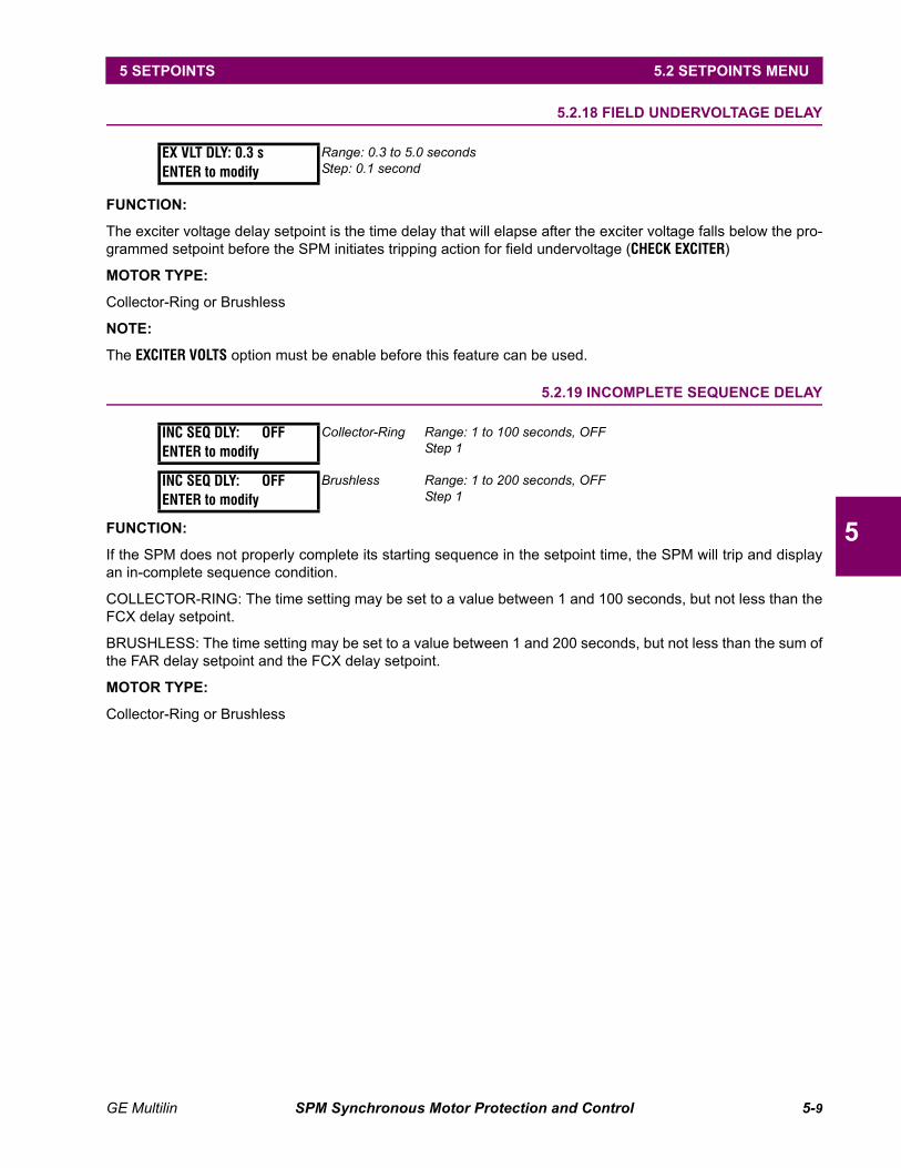
GE Multilin SPM Synchronous Motor Protection and Control 5-9
5 SETPOINTS 5.2 SETPOINTS MENU
5
5.2.18 FIELD UNDERVOLTAGE DELAY
FUNCTION:
The exciter voltage delay setpoint is the time delay that will elapse after the exciter voltage falls below the pro-grammed setpoint before the SPM initiates tripping action for field undervoltage (CHECK EXCITER)
MOTOR TYPE:
Collector-Ring or Brushless
NOTE:
The EXCITER VOLTS option must be enable before this feature can be used.
5.2.19 INCOMPLETE SEQUENCE DELAY
FUNCTION:
If the SPM does not properly complete its starting sequence in the setpoint time, the SPM will trip and displayan in-complete sequence condition.
COLLECTOR-RING: The time setting may be set to a value between 1 and 100 seconds, but not less than theFCX delay setpoint.
BRUSHLESS: The time setting may be set to a value between 1 and 200 seconds, but not less than the sum ofthe FAR delay setpoint and the FCX delay setpoint.
MOTOR TYPE:
Collector-Ring or Brushless
EX VLT DLY: 0.3 sENTER to modify
Range: 0.3 to 5.0 secondsStep: 0.1 second
INC SEQ DLY: OFFENTER to modify
Collector-Ring Range: 1 to 100 seconds, OFFStep 1
INC SEQ DLY: OFFENTER to modify
Brushless Range: 1 to 200 seconds, OFFStep 1

5-10 SPM Synchronous Motor Protection and Control GE Multilin
5.3 OPTIONAL POWER FACTOR REGULATION SETPOINTS 5 SETPOINTS
5
5.3 OPTIONAL POWER FACTOR REGULATION SETPOINTS 5.3.1 DESCRIPTION
The following parameters can be adjusted while the motor is running. See Section 7.5, Regulator Tune UpInstructions.
5.3.2 POWER FACTOR REGULATOR
FUNCTION:
The SPM is capable of providing a Closed-loop PF Regulator with a very fast response. The regulator may beset up to regulate motor power factor in a range between 0.9 lagging to 1.0 (unity) to 0.0 leading power factor.This setpoint determines at what power factor the regulator will operate. The regulator may be disabled inorder to output the floor value (see FLOOR VOLTS parameter) by entering OFF. This enables the operator to setup base-field amperes, then the regulator power factor may be returned to its normal setting and the regulatorwill function normally.
MOTOR TYPE:
Collector-Ring
5.3.3 REGULATOR GAIN
FUNCTION:
Adjust this setpoint for optimum regulator performance.
MOTOR TYPE:
Collector-Ring
5.3.4 STABILITY
FUNCTION:
This setpoint determines the number of most recent regulator output calculations to be averaged in order tohelp compensate for instability. Regulator calculations are performed once every 100 milliseconds.
MOTOR TYPE:
Collector-Ring
NOTE:
This eliminates the need for an external RC lag compensation network.
REG PF: 0.00ENTER to modify
Range: –0.90 to 1.00, OFFStep: 0.01
REG GAIN: 0.00ENTER to modify
Range: 1 to 100Step: 1
STABILITY: 1 cycENTER to modify
Range: 1 to 60 cyclesStep: 1

GE Multilin SPM Synchronous Motor Protection and Control 5-11
5 SETPOINTS 5.3 OPTIONAL POWER FACTOR REGULATION SETPOINTS
5
5.3.5 REGULATOR OUTPUT LIMIT
FUNCTION:
This setpoint is the upper limit of the range of the control signal output voltage. This value must match the inputrange of the separate variable excitation equipment.
MOTOR TYPE:
Collector-Ring
NOTE:
This value must be greater than or equal to the FLOOR VOLTS setpoint.
5.3.6 FLOOR VOLTS
FUNCTION:
The floor value is the minimum limit for output control signal voltage that is connected to the field-rectifierequipment. The value programmed here is the exact output voltage from the SPM. For example, if the floor isprogrammed at 1.5 the SPM will output 1.5-volts minimum.
MOTOR TYPE:
Collector-Ring
NOTE:
This value must be less than or equal to the REG OUTPUT setpoint.
APPLICATION:
Certain conditions of operation require a floor so that the motor power factor will not become unstable if thefield cur-rent is drastically reduced.
When the floor overrides the regulator, the power factor moves in a more leading condition than the regulatorsetpoint. As the load and/or system force the motor power factor toward the lagging condition such that thepower factor falls below the regulator setpoint, the regulator will once again take control and boost the fieldabove the floor so that the power factor will not dip below the setpoint. The power factor regulator must betuned during initial start-up. See section 6-6 for regulator tune up instructions.
REG OUTPUT: 1 VENTER to modify
Range: 0 to 10 VStep: 1Dependent on the FLOOR VOLTS setpoint.
FLOOR VOLTS: 0.0ENTER to modify
Range: 0.0 to 10 VStep: 0.1

5-12 SPM Synchronous Motor Protection and Control GE Multilin
5.4 CONFIGURATIONS MENU 5 SETPOINTS
5
5.4 CONFIGURATIONS MENU 5.4.1 MOTOR TYPE
FUNCTION:
The type of motor is selected here. Different setpoints are used for the two different motors and operation ofthe relay is altered. This configuration setpoint must be entered correctly.
5.4.2 LINE FREQUENCY
FUNCTION:
Enter line frequency here for system.
5.4.3 POWER FACTOR REFERENCE
FUNCTION:
Enter the source for the voltage reference for power factor calculations. See Section 2.4, Electrical installationfor proper wiring details.
5.4.4 RTU ADDRESS
FUNCTION:
Enter the Modbus slave address here which must be unique to all SPMs on the same communication link.
5.4.5 BAUD RATE
FUNCTION:
This setpoint allows the user to select the desired baud rate.
5.4.6 PARITY
FUNCTION:
Enter the type of parity necessary.
MOTOR: Collr-RingENTER to modify
Range: Collr-Ring, Brushless
LINE FREQ: 60 HzENTER to modify
Range: 50 Hz, 60 Hz
PF REF: InternalENTER to modify
Range: Internal, External
RTU ADDRESS: 1ENTER to modify
Range: 1 to 254Step: 1
BAUD RATE: 19.2kENTER to modify
Range: 300, 600, 2400, 4800, 9600, 19.2k, 38.4k, 57.6k, 115k
PARITY: NoneENTER to modify
Range: None, Odd, Even

GE Multilin SPM Synchronous Motor Protection and Control 5-13
5 SETPOINTS 5.4 CONFIGURATIONS MENU
5
5.4.7 TURNAROUND
FUNCTION:
Turnaround is the delay before the relay changes from transmit to receive or vice versa. This setpoint need notbe adjusted unless operating on a very slow system.
5.4.8 STATUS MODE
FUNCTION:
This setpoint allows the user to configure the parameters in the STATUS MODE such that they are read only orread/writeable.
5.4.9 PASSWORD
FUNCTION:
This allows the user to program a new password other then the factory default to restrict access to programma-ble feature on the SPM.
TURNAROUND: 5ENTER to modify
Range: 0 to 1000 msStep: 1
STAT: read onlyENTER to modify
Range: read only, read/write
PASSWORD: 0000ENTER to modify
Range: 0000 to 9999Step: 1
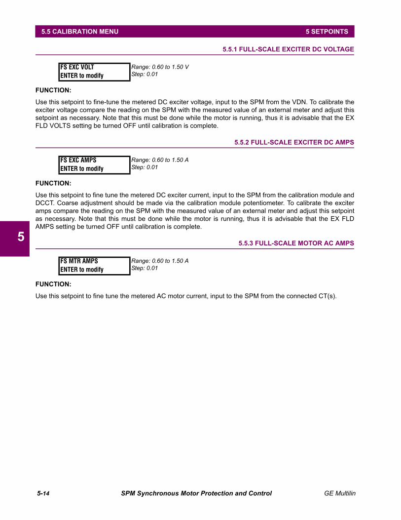
5-14 SPM Synchronous Motor Protection and Control GE Multilin
5.5 CALIBRATION MENU 5 SETPOINTS
5
5.5 CALIBRATION MENU 5.5.1 FULL-SCALE EXCITER DC VOLTAGE
FUNCTION:
Use this setpoint to fine-tune the metered DC exciter voltage, input to the SPM from the VDN. To calibrate theexciter voltage compare the reading on the SPM with the measured value of an external meter and adjust thissetpoint as necessary. Note that this must be done while the motor is running, thus it is advisable that the EXFLD VOLTS setting be turned OFF until calibration is complete.
5.5.2 FULL-SCALE EXCITER DC AMPS
FUNCTION:
Use this setpoint to fine tune the metered DC exciter current, input to the SPM from the calibration module andDCCT. Coarse adjustment should be made via the calibration module potentiometer. To calibrate the exciteramps compare the reading on the SPM with the measured value of an external meter and adjust this setpointas necessary. Note that this must be done while the motor is running, thus it is advisable that the EX FLDAMPS setting be turned OFF until calibration is complete.
5.5.3 FULL-SCALE MOTOR AC AMPS
FUNCTION:
Use this setpoint to fine tune the metered AC motor current, input to the SPM from the connected CT(s).
FS EXC VOLTENTER to modify
Range: 0.60 to 1.50 VStep: 0.01
FS EXC AMPSENTER to modify
Range: 0.60 to 1.50 AStep: 0.01
FS MTR AMPSENTER to modify
Range: 0.60 to 1.50 AStep: 0.01

GE Multilin SPM Synchronous Motor Protection and Control 6-1
6 ACTUAL VALUES 6.1 DISPLAY SCROLLING
6
6 ACTUAL VALUES 6.1 DISPLAY SCROLLING 6.1.1 DESCRIPTION
FUNCTION:
PWR FACTOR: Displays the power factor of the motor. 1.00 is unity, positive values are leading and negativevalues are lagging.
DC AMPS: Displays the exciter/field current in DC Amps.
DC VOLTS: Displays the exciter/field voltage in DC Volts.
EXC FIELD: Displays the exciter field resistance in Ohms.
AC AMPS: Displays the motor phase current in AC Amps.
NOTE:
These values can only be seen when the motor is running.
PWR FACTOR: 1.00DC AMPS: 0 ADC VOLTS: 0 VEXC FIELD: 0 ΩAC AMPS: 0 A
The display auto-scrolls through actual values when the motor is running. The operator can use the scroll keys to view specific values.
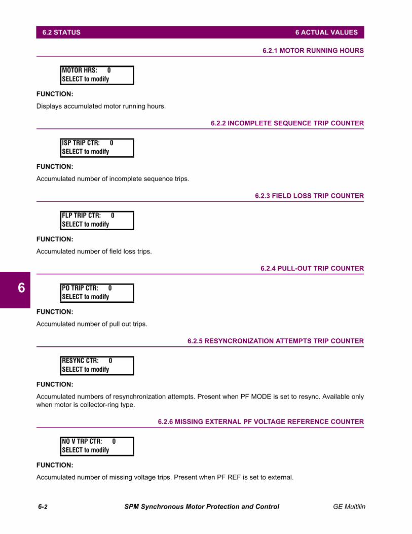
6-2 SPM Synchronous Motor Protection and Control GE Multilin
6.2 STATUS 6 ACTUAL VALUES
6
6.2 STATUS 6.2.1 MOTOR RUNNING HOURS
FUNCTION:
Displays accumulated motor running hours.
6.2.2 INCOMPLETE SEQUENCE TRIP COUNTER
FUNCTION:
Accumulated number of incomplete sequence trips.
6.2.3 FIELD LOSS TRIP COUNTER
FUNCTION:
Accumulated number of field loss trips.
6.2.4 PULL-OUT TRIP COUNTER
FUNCTION:
Accumulated number of pull out trips.
6.2.5 RESYNCRONIZATION ATTEMPTS TRIP COUNTER
FUNCTION:
Accumulated numbers of resynchronization attempts. Present when PF MODE is set to resync. Available onlywhen motor is collector-ring type.
6.2.6 MISSING EXTERNAL PF VOLTAGE REFERENCE COUNTER
FUNCTION:
Accumulated number of missing voltage trips. Present when PF REF is set to external.
MOTOR HRS: 0SELECT to modify
ISP TRIP CTR: 0SELECT to modify
FLP TRIP CTR: 0SELECT to modify
PO TRIP CTR: 0SELECT to modify
RESYNC CTR: 0SELECT to modify
NO V TRP CTR: 0SELECT to modify
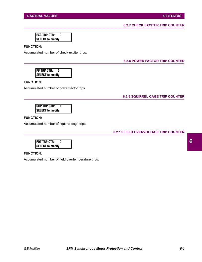
GE Multilin SPM Synchronous Motor Protection and Control 6-3
6 ACTUAL VALUES 6.2 STATUS
6
6.2.7 CHECK EXCITER TRIP COUNTER
FUNCTION:
Accumulated number of check exciter trips.
6.2.8 POWER FACTOR TRIP COUNTER
FUNCTION:
Accumulated number of power factor trips.
6.2.9 SQUIRREL CAGE TRIP COUNTER
FUNCTION:
Accumulated number of squirrel cage trips.
6.2.10 FIELD OVERVOLTAGE TRIP COUNTER
FUNCTION:
Accumulated number of field overtemperature trips.
EXC TRP CTR: 0SELECT to modify
PF TRP CTR: 0SELECT to modify
SCP TRP CTR: 0SELECT to modify
FOT TRP CTR: 0SELECT to modify

6-4 SPM Synchronous Motor Protection and Control GE Multilin
6.2 STATUS 6 ACTUAL VALUES
6

GE Multilin SPM Synchronous Motor Protection and Control 7-1
7 TESTING AND TROUBLESHOOTING 7.1 START-UP PROCEDURE
7
7 TESTING AND TROUBLESHOOTING 7.1 START-UP PROCEDURE 7.1.1 INSPECTION
Inspect all wiring and verify that the connections are clean, tight, and there is adequate clearance for all de-vices. All external wiring from the controller must be made in strict accordance with the main connection dia-gram supplied with the controller.
While referring to the main connection diagram supplied with the controller, inspect the wiring to determine withcertainty that the starting and field-discharge resistor is connected in the motor field-discharge circuit throughthe discharge (closed) contact of the field-applying contactor (FC).
While inspecting the field contactor, manually pick up the contactor and confirm that the normally-closed con-tactor pole opens after the two normally-open poles close. It is important that all three poles are closedmomentarily (overlap) during contactor pick-up and drop out (closed transition contacts).
To clean the face of the SPM, wipe with a damp cloth and mild detergent.
7.1.2 SPM TEST CHECKS
After the wiring check is complete, the equipment may be energized but DO NOT START MOTOR. With con-trol power on, carefully follow the procedures below.
DO NOT TOUCH ANY CONNECTION POINT AT THE REAR OF THE SPM. POTENTIALS UP TO1000 V MAY BE PRESENT ACROSS INPUTS VF + AND VF –.
a) STANDBY MODE
1. Apply control power ONLY (do NOT start the motor).
2. The unit should power up and indicate that it is performing its power-on self-test. When this test is success-fully completed, the motor type is shown (collector-ring or brushless) and SPM READY should be blinking onthe display. If not, then a problem exists with the microprocessor or a peripheral device.
3. Obtain a list of the factory programmed setpoints and review the SPM setpoints. See Section 5.2: SET-POINTS MENU on page 5–2 for information on setpoints.
b) TEST MODE
Built-in diagnostics ensure the unit is operational prior to start-up. The SPM is placed in TEST MODE as follows:
1. Press the GE key to enter the STAT MODE menu.
2. Press the GE key again to enter the PROGRAMMING MODE menu.
3. Press the GE key one more time to enter the TEST MODE menu.
4. Select the required test then press to begin testing. There are three tests to choose from: systemtest (SYSTEM TEST), squirrel cage protection test (SC PROT TEST), and synchronization and power factor test(SYNC AND PF TEST). When entering test mode, the SPM responds by opening (de-energizing) the TRIPrelay contacts. When exiting test mode, the SPM responds by closing (energizing) the TRIP relay contacts.
• SYSTEM TEST: The SPM performs a complete system test on internal memory, input-output devices,timers, and other system functions. The results are displayed as the test progresses. The testsequence will report any failures. If a failure persists after two or three attempts, the unit should bereplaced. The SPM must be reset if the test fails.
DO NOT DEFEAT THE SPM MOTOR RESTART PROTECTION BY SWITCHING THECONTROL POWER ON AND OFF. THIS ACTION RESETS THE STALL TIMECOUNTERS AND DEFEATS MOTOR PROTECTION FROM FREQUENT RESTARTS.
CAUTION
ENTER
CAUTION
7-2 SPM Synchronous Motor Protection and Control GE Multilin
7.1 START-UP PROCEDURE 7 TESTING AND TROUBLESHOOTING
7
• Squirrel Cage Protection Test (SC PROT TEST): An internal SCP test frequency is inserted into theSCP program. After a time delay corresponding to the STALL TIME setpoint, the display reads SQLCAGE TRIP!. Press any key to reset.
• Synchronization and Power Factor Test (SYNC AND PF TEST): An internal slip frequency is injectedinto the synchronizing circuitry and slowly glides downward (simulating an accelerating motor).When this frequency matches the SYNC SLIP setpoint, the display flashes FIELD IS APPLIED and theFAR relay picks up, followed by the FCX after the FCX DELAY time setpoint. Next, the SPM automat-ically tests the power factor circuitry by internally generating a test power factor signal. No operatorinterface is required to proceed from the synchronizing test to the power factor test. This signalslowly decreases until it dips below the PF TRIP setpoint. After the PF DELAY setpoint time, the dis-play reads PWR FACTOR TRIP!. Press any key to reset the unit. If SPM is in the RESYNC mode, theSPM may attempt to re-synchronize. If it does, the FIELD IS APPLIED message is displayed momen-tarily before a power factor trip occurs.
5. To leave TEST MODE, press and release the GE key until SPM READY is displayed again.
BE SURE TO STOP THE MOTOR AND DE-ENERGIZE ALL POWER BEFORE CHANGING ANYLEADS.
7.1.3 START-UP DESCRIPTION
Closing the feeder to the controller unit provides power to the control circuits and to the SPM. Energizing theSPM causes the TRIP relay contacts (terminals TRP1–TRP2) to close and the SPM to display SPM READY.Refer to Figure 2–4: PANEL AND TERMINAL LAYOUT on page 2–5 for trip relay contact locations and Figure2–3: TYPICAL WIRING DIAGRAM on page 2–4 for wiring details.
Pressing the START button picks up relay MX, which in turn energizes the coil of main contactor M. When Mcloses and applies AC power to the motor, induced field current flows through the field discharge resistor andan associated voltage drop appears across terminals VF + and VF –. The frequency of this induced field voltagedecreases as the motor speed increases, and the speed sensing circuits of the SPM cause the FAR relay toclose as the motor reaches the programmed slip value. When the FAR relay contacts (terminals FAR1–FAR2)close, the field contactor (FC) closes and applies excitation to the motor from the exciter.
After the programmed FCX DELAY, the FCX relay picks up and closes its contacts, allowing the customer's auto-matic loading circuits to be activated.
WARNING
GE Multilin SPM Synchronous Motor Protection and Control 7-3
7 TESTING AND TROUBLESHOOTING 7.2 DISPLAY AND MESSAGES
7
7.2 DISPLAY AND MESSAGES 7.2.1 DISPLAY
The SPM uses the alphanumeric display to indicate the following information:
• programming prompts
• SPM trip explanations
• readout of the desired motor running parameters
The motor running parameters are displayed as follows.
• Before start, the SPM displays SPM READY.
• While starting, the power factor and line amperes are displayed.
• When the field contactor closes, the SPM momentarily displays FIELD IS APPLIED followed by the normalrunning display of line current, field current (if this option is furnished), and motor power factor. The “+” indi-cates leading power factor (motor generating reactive power) while "–" indicates lagging power factor(motor consuming reactive power). The unity (1.0) power factor display may have a "+" or "–" sign indicat-ing that power factor is just slightly leading or lagging.
• Once the motor has synchronized, the SPM displays power factor, line current, field volts (if optioned), fieldcurrent (if optioned), and field ohms (if optioned).
7.2.2 SPM MESSAGES
The SPM has a number of built-in messages that may appear during normal operation or if an error isdetected. Errors may occur because the CPU detects a problem internal to the SPM. These messages areexplained in detail below.
• FIELD IS APPLIED: This message appears when the SPM has closed the field contactor. It is displayed brieflyand is a normal SPM function.
• PWR FACTOR TRIP: The motor has been operating below the power factor setpoint too long causing a trip.
• CHECK EXCITER: The field voltage is below the minimum entered in the field undervoltage setpoint. Theexciter should be checked to determine that it is functioning properly. Also, the setpoint should be exam-ined to see if it is set too high for the normal exciter output.
• FIELD LOSS TRIP!: The field current is less than the field current setpoint. The exciter should be checked forproper output and the field current setpoint should be checked.
• MISSING VOLTAGE!: The SPM is NOT receiving a power factor reference voltage input to terminals V1EXTand V2EXT and PF REF is set to External.
• SQL CAGE TRIP!: The SPM has tripped the motor off-line due to a squirrel cage protection trip. The motormust be allowed to cool for the amount of time displayed by the SPM.
• PULL-OUT TRIP!: A trip has been caused by motor line current exceeding 4 times the full load current set-point for longer than the PF delay time.
• INCOM SEQ TRIP!: The SPM has tripped the motor due to an incomplete sequence fault. The source of thefault should be located before the motor is restarted.
• PULL-OUT TRIP!: The SPM has tripped the motor due to pull-out.
• FIELD OVERTEMP!: The SPM has tripped the motor due to overtemperature on the field windings.
• FAIL TO RESYNC!: The SPM has tripped the motor due to a failure to resynchronize.
• START INHIBITED! Ready in xxx min.: The SPM has tripped the motor and will not allow a restart attempt forxxx minutes.

7-4 SPM Synchronous Motor Protection and Control GE Multilin
7.2 DISPLAY AND MESSAGES 7 TESTING AND TROUBLESHOOTING
7
• RUN-TIME FAULT: The CPU has calculated a series of values within a set time limit that are out of their validranges. Power must be cycled to the unit to correct this error.
• ROM FAILURE: A PROM checksum error occurred during self-test. Consult GE Multilin to correct this prob-lem.
• NOVRAM FAILURE: After the SPM writes data to its non-volatile memory (E2PROM), the CPU immediatelyreads back the last value and compares it to what should have been written. If the two values are notequal, the SPM displays this message. This generally indicates a problem with the CPU Board. The SPMshould be replaced.
• RAM FAILURE: A RAM checksum error occurred during self-test. This error is sometimes cleared by cyclingpower through the unit. Otherwise, consult GE Multilin.
• FPGA FAILURE: The Field Programmable Gate Array has failed to configure during self-test. Power can becycled to the unit in an attempt to clear this error. Otherwise, consult the GE Multilin.
• CHECK MX & TRP CIRCUIT: The motor is in a tripped state. Either the MX contacts are still open and the TRIPrelay is de-energized, or the TRIP relay is energized but the internal circuitry to sense this has failed.
• MX or TRP FAILURE: The MX circuit or the TRIP relay circuit has failed.
• COMM CARD FAILURE: The communications card has failed or was not present during power up or SYSTEMTEST. A periodic display of this error occurs only if a communication card test was passed during power-upand subsequently fails during normal operation. Only for units with the communications option.
• WDT CKT FAILURE: The watchdog timer circuit has failed during self-test.
• INCOMPLETE SETUP: The internal configuration information (not user selectable) has been lost and the unitwill not function. The SPM must be returned to GE Multilin for correction of this problem.
• CALIBRATION REQD: The SPM has lost the calibration information stored in its non-volatile memory. The unitmust be returned to GE Multilin for correction of this problem.
• FORCED WDT TRIP: The TRIP relay has been told to de-energize but is still showing as energized. In thiscondition, the CPU forces a watchdog timer trip in an attempt to de-energize the TRIP relay.
• See Users Manual: Consult the user manual for correction.
Press any key to clear a trip messages such as PWR FACTOR TRIP! or SQL CAGE TRIP!.
DO NOT DEFEAT THE MOTOR RESTART PROTECTION PROVIDED BY THE SPM BY SWITCH-ING THE CONTROL POWER ON AND OFF. THE ABOVE ACTION RESETS THE STALL TIMECOUNTERS WHICH DEFEATS MOTOR PROTECTION FROM FREQUENT RESTARTS.
NOTE
CAUTION
GE Multilin SPM Synchronous Motor Protection and Control 7-5
7 TESTING AND TROUBLESHOOTING 7.3 REGULATOR TUNE-UP
7
7.3 REGULATOR TUNE-UP 7.3.1 INSTRUCTIONS
Following these instructions will permit tune-up of the regulator during the initial start-up of the motor. Performall start-up procedures in Section 7.1: START-UP PROCEDURE on page 7–1 before proceeding.
1. Enter the following initial values into the SPM (see Section 5.3: OPTIONAL POWER FACTOR REGULA-TION SETPOINTS on page 5–10 for additional information on these setpoints):
REG PF = OFFSTABILITY = 1 cycREG GAIN = 10REG. OUTPUT = 10 VFLOOR = 5.0 V
• Setting REG PF = OFF places FLOOR in control of the motor field. The power factor regulator is disabled.
• FLOOR = 5.0 V is sufficiently high enough to not trip the motor due to underexcitation when started.
2. After the above values are stored in memory and SPM READY is displayed, start the motor (unloaded if pos-sible) and allow it to synchronize. The display should indicate a leading (positive) power factor.
3. To facilitate regulator tune-up, the five power factor regulator parameters can be changed while the motoris running. These are the only parameters that can be changed while in the "tuning mode".
To get in "tuning mode" while the motor is running, enter programming mode and scroll to the REGULATORTUNING menu. Press the key to enter the menu.
4. Press / until the FLOOR VOLTS setpoint is displayed. Adjust the motor field current for a desiredminimum (typically between 80 to 100% of rated field current). Change the floor value to a value above orbelow the initial value of 5.0, depending on whether more or less field current is desired. The floor parame-ter is the output voltage across the PF regulator output terminals +N and –N.
This method of parameter entry can only be employed while the motor is running and only for thefive power factor regulator parameters.
5. Once the desired minimum motor field current is obtained, press to deselect FLOOR VOLTS. Press/ until the PF REG setpoint appears. Program the desired power factor (typically between 0.8 and
1.0). The control of the motor field current should now be in control of the closed-loop power factor regula-tor. Press again to deselect the PF REG setpoint.
6. Reset the REG OUTPUT setpoint to the original factory setting. This setpoint has been chosen to match theinput of the separate variable exciter.
7. The regulator gain setpoint can probably be left at 10. However, should instability (hunting) occur, or ifmore optimum response is desired, the gain may be increased or decreased as desired. Press /until REG GAIN appears in the display and enter new setpoints (range 1 to 100) using the same procedureas for the FLOOR and REG PF setpoints. The optimum gain is the highest possible gain setting without powerfactor instability detectable by a fluctuating exciter output and power factor. If instability still occurs, thenincrease the value of the STABILITY setpoint as required to dampen the fluctuating power factor. Theseparameters are automatically stored in the E2PROM when the motor is shut down.
Do not attempt to regulate 1.0 power factor with an unloaded or lightly loaded machine. A synchro-nous machine running unloaded at or near unity power factor is inherently unstable and will probablybe tripped from power factor protection. Adjust the FLOOR setpoint high enough to override the regula-tor and avoid the instability while allowing the PF to move near zero lead power factor.
ENTER
NOTE
ENTER
ENTER
NOTE
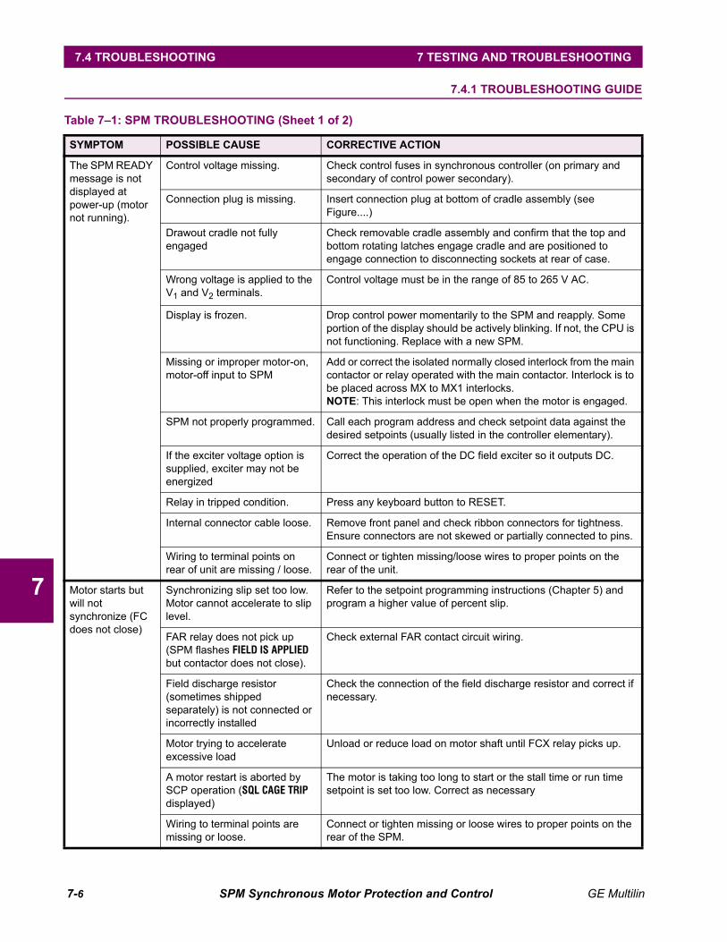
7-6 SPM Synchronous Motor Protection and Control GE Multilin
7.4 TROUBLESHOOTING 7 TESTING AND TROUBLESHOOTING
7
7.4 TROUBLESHOOTING 7.4.1 TROUBLESHOOTING GUIDE
Table 7–1: SPM TROUBLESHOOTING (Sheet 1 of 2)
SYMPTOM POSSIBLE CAUSE CORRECTIVE ACTION
The SPM READY message is not displayed at power-up (motor not running).
Control voltage missing. Check control fuses in synchronous controller (on primary and secondary of control power secondary).
Connection plug is missing. Insert connection plug at bottom of cradle assembly (see Figure....)
Drawout cradle not fully engaged
Check removable cradle assembly and confirm that the top and bottom rotating latches engage cradle and are positioned to engage connection to disconnecting sockets at rear of case.
Wrong voltage is applied to the V1 and V2 terminals.
Control voltage must be in the range of 85 to 265 V AC.
Display is frozen. Drop control power momentarily to the SPM and reapply. Some portion of the display should be actively blinking. If not, the CPU is not functioning. Replace with a new SPM.
Missing or improper motor-on, motor-off input to SPM
Add or correct the isolated normally closed interlock from the main contactor or relay operated with the main contactor. Interlock is to be placed across MX to MX1 interlocks.NOTE: This interlock must be open when the motor is engaged.
SPM not properly programmed. Call each program address and check setpoint data against the desired setpoints (usually listed in the controller elementary).
If the exciter voltage option is supplied, exciter may not be energized
Correct the operation of the DC field exciter so it outputs DC.
Relay in tripped condition. Press any keyboard button to RESET.
Internal connector cable loose. Remove front panel and check ribbon connectors for tightness. Ensure connectors are not skewed or partially connected to pins.
Wiring to terminal points on rear of unit are missing / loose.
Connect or tighten missing/loose wires to proper points on the rear of the unit.
Motor starts but will not synchronize (FC does not close)
Synchronizing slip set too low. Motor cannot accelerate to slip level.
Refer to the setpoint programming instructions (Chapter 5) and program a higher value of percent slip.
FAR relay does not pick up (SPM flashes FIELD IS APPLIED but contactor does not close).
Check external FAR contact circuit wiring.
Field discharge resistor (sometimes shipped separately) is not connected or incorrectly installed
Check the connection of the field discharge resistor and correct if necessary.
Motor trying to accelerate excessive load
Unload or reduce load on motor shaft until FCX relay picks up.
A motor restart is aborted by SCP operation (SQL CAGE TRIP displayed)
The motor is taking too long to start or the stall time or run time setpoint is set too low. Correct as necessary
Wiring to terminal points are missing or loose.
Connect or tighten missing or loose wires to proper points on the rear of the SPM.
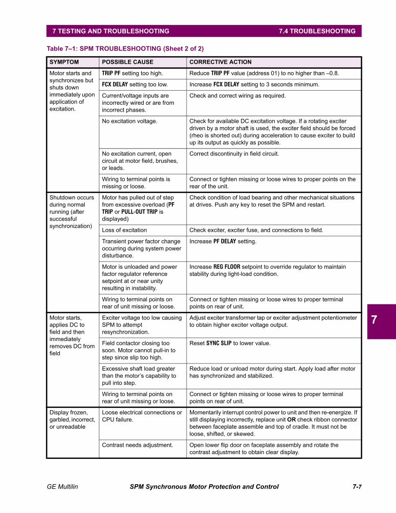
GE Multilin SPM Synchronous Motor Protection and Control 7-7
7 TESTING AND TROUBLESHOOTING 7.4 TROUBLESHOOTING
7
Motor starts and synchronizes but shuts down immediately upon application of excitation.
TRIP PF setting too high. Reduce TRIP PF value (address 01) to no higher than –0.8.
FCX DELAY setting too low. Increase FCX DELAY setting to 3 seconds minimum.
Current/voltage inputs are incorrectly wired or are from incorrect phases.
Check and correct wiring as required.
No excitation voltage. Check for available DC excitation voltage. If a rotating exciter driven by a motor shaft is used, the exciter field should be forced (rheo is shorted out) during acceleration to cause exciter to build up its output as quickly as possible.
No excitation current, open circuit at motor field, brushes, or leads.
Correct discontinuity in field circuit.
Wiring to terminal points is missing or loose.
Connect or tighten missing or loose wires to proper points on the rear of the unit.
Shutdown occurs during normal running (after successful synchronization)
Motor has pulled out of step from excessive overload (PF TRIP or PULL-OUT TRIP is displayed)
Check condition of load bearing and other mechanical situations at drives. Push any key to reset the SPM and restart.
Loss of excitation Check exciter, exciter fuse, and connections to field.
Transient power factor change occurring during system power disturbance.
Increase PF DELAY setting.
Motor is unloaded and power factor regulator reference setpoint at or near unity resulting in instability.
Increase REG FLOOR setpoint to override regulator to maintain stability during light-load condition.
Wiring to terminal points on rear of unit missing or loose.
Connect or tighten missing or loose wires to proper terminal points on rear of unit.
Motor starts, applies DC to field and then immediately removes DC from field
Exciter voltage too low causing SPM to attempt resynchronization.
Adjust exciter transformer tap or exciter adjustment potentiometer to obtain higher exciter voltage output.
Field contactor closing too soon. Motor cannot pull-in to step since slip too high.
Reset SYNC SLIP to lower value.
Excessive shaft load greater than the motor’s capability to pull into step.
Reduce load or unload motor during start. Apply load after motor has synchronized and stabilized.
Wiring to terminal points on rear of unit missing or loose.
Connect or tighten missing or loose wires to proper terminal points on rear of unit.
Display frozen, garbled, incorrect, or unreadable
Loose electrical connections or CPU failure.
Momentarily interrupt control power to unit and then re-energize. If still displaying incorrectly, replace unit OR check ribbon connector between faceplate assemble and top of cradle. It must not be loose, shifted, or skewed.
Contrast needs adjustment. Open lower flip door on faceplate assembly and rotate the contrast adjustment to obtain clear display.
Table 7–1: SPM TROUBLESHOOTING (Sheet 2 of 2)
SYMPTOM POSSIBLE CAUSE CORRECTIVE ACTION

7-8 SPM Synchronous Motor Protection and Control GE Multilin
7.5 PROGRAMMING 7 TESTING AND TROUBLESHOOTING
7
7.5 PROGRAMMING 7.5.1 PROGRAMMING EXAMPLE
The following example uses the following motor data and should be referred to as the example progresses.The data is for a 400 hp 4000 V ring-type motor. We will assume that all of the optional features available withthe SPM have been installed. The following pages show the keypresses made by the operator, the SPM dis-play response, and comments concerning the programming operation. The SPM READY message should be dis-played at the beginning of the operation. Refer to Chapter 7 for programming the SPM for brush-less motors.
Motor: 400 hp, PF = –0.8, 720 RPM, 4000 V.Induced field current: 0% SPD, 30 A; 95% SPD, 17 A.Recommended field discharge resistance: 21 ΩAllowable stall time: 7 seconds50 percent run time: 11 seconds.
The induced field voltage (product of induced field in amperes and discharge resistance in ohms)must fall between 200 and 1000 V at both zero and 95% speed. For this example:
21 Ω × 30 A = 630 V (zero speed check)21 Ω × 17 A = 357 V (95% speed check)
The criterion is thus met for this example.
If induced field voltage is greater than 1000 volts, contact the factory
Table 7–2: PROGRAMMING EXAMPLE (Sheet 1 of 4)
KEYPRESS DISPLAY COMMENTS
None Ready-mode display
Enter STAT mode on the way to PROGRAMMING MODE
In PROGRAMMING MODE - must now enter the password
Use SCROLL keys to enter password and then press ENTER to verify the password
First menu after password entry is CONFIGURATIONS menu - must scroll past it to get to SETPOINTS menu
Press SELECT/ENTER key to enter setpoint menus
First setpoint is PF TRIP. SCROLL Key(s) to select value of -0.85 and then SELECT/ENTER key to accept new value.
, Change existing value of PF TRIP to new –0.85 value.
NOTE
Coll-Ring MotorSPM READY
STAT MODESCROLL for menus
PROGRAMMING MODESCROLL passwords
PASSWORD: 0000ENTER to verify
ENTER CONFIGURATIONS?ENTER for menus
SETPOINTS?ENTER for menus
ENTER PF TRIP: –0.80ENTER to modify
ENTER PF TRIP: –0.85ENTER to modify

GE Multilin SPM Synchronous Motor Protection and Control 7-9
7 TESTING AND TROUBLESHOOTING 7.5 PROGRAMMING
7
, Select the setpoint. Use the scroll key(s) to select value of 5.0 seconds and then ENTER to accept new value
, Change the existing value of PF DELAY to 5.0
This value will remain as is.
, Select the setpoint. Use the scroll keys to move to the PF MODE setpoint and then ENTER to select the setpoint.
, Change the existing value of PF MODE to resync. Use the scroll keys to select value of resync and then ENTER to accept new value.
Press the scroll down key to move to the FCX delay setpoint. This value will remain as is.
, SCROLL DOWN key to move to the AC CT RTG setpoint and then SELECT/ENTER key to select the setpoint.
, Change the existing value of AC CT RTG to 100. SCROLL Key(s) to select the value of 100 then SELECT/ENTER key to accept new value.
, SCROLL DOWN key to move to the FL AMPS setpoint and then SELECT/ENTER key to select the setpoint
, Changes existing value of FL AMPS to 56. SCROLL Key(s) to select value of 58 and then SELECT/ENTER key to accept new value
, SCROLL DOWN key to move to the LR AMPS setpoint and then SELECT/ENTER to select the setpoint
, Change the existing value of LR AMPS to 226. SCROLL Key(s) to select value of 226 and then SELECT/ENTER key to accept new value
, SCROLL DOWN key to the SYNC SLIP set-point and then SELECT/ENTER key to select the setpoint
, Change the existing value of SYNC SLIP to 4.0%. SCROLL Key(s) to select value of 4% and then SELECT/ENTER key to accept new value
Table 7–2: PROGRAMMING EXAMPLE (Sheet 2 of 4)
KEYPRESS DISPLAY COMMENTS
ENTER PF DELAY: 10.0 sENTER to modify
ENTER PF DELAY: 5.0 sENTER to modify
PF SUPP: 6% FLCENTER to modify
ENTER PF MODE: ridethruENTER to modify
ENTER PF MODE: resyncSCROLL to change
FCX DELAY: 1 sENTER to modify
ENTER AC CT RTG: 10/5ENTER to modify
ENTER AC CT RTG: 100/5SCROLL to change
ENTER FL AMPS: 10ENTER to modify
ENTER FL AMPS: 58SCROLL to change
ENTER LR AMPS: 116ENTER to modify
ENTER LR AMPS: 226SCROLL to change
ENTER SYNC SLIP: 0.5%ENTER to modify
ENTER SYNC SLIP: 4.0%SCROLL to change
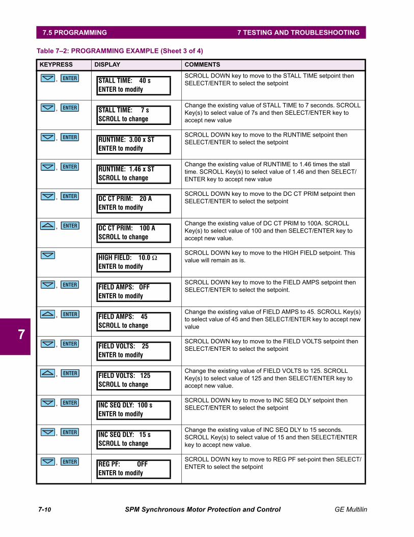
7-10 SPM Synchronous Motor Protection and Control GE Multilin
7.5 PROGRAMMING 7 TESTING AND TROUBLESHOOTING
7
, SCROLL DOWN key to move to the STALL TIME setpoint then SELECT/ENTER to select the setpoint
, Change the existing value of STALL TIME to 7 seconds. SCROLL Key(s) to select value of 7s and then SELECT/ENTER key to accept new value
, SCROLL DOWN key to move to the RUNTIME setpoint then SELECT/ENTER to select the setpoint
, Change the existing value of RUNTIME to 1.46 times the stall time. SCROLL Key(s) to select value of 1.46 and then SELECT/ENTER key to accept new value
, SCROLL DOWN key to move to the DC CT PRIM setpoint then SELECT/ENTER to select the setpoint
, Change the existing value of DC CT PRIM to 100A. SCROLL Key(s) to select value of 100 and then SELECT/ENTER key to accept new value.
SCROLL DOWN key to move to the HIGH FIELD setpoint. This value will remain as is.
, SCROLL DOWN key to move to the FIELD AMPS setpoint then SELECT/ENTER to select the setpoint.
, Change the existing value of FIELD AMPS to 45. SCROLL Key(s) to select value of 45 and then SELECT/ENTER key to accept new value
, SCROLL DOWN key to move to the FIELD VOLTS setpoint then SELECT/ENTER to select the setpoint
, Change the existing value of FIELD VOLTS to 125. SCROLL Key(s) to select value of 125 and then SELECT/ENTER key to accept new value.
, SCROLL DOWN key to move to INC SEQ DLY setpoint then SELECT/ENTER to select the setpoint
, Change the existing value of INC SEQ DLY to 15 seconds. SCROLL Key(s) to select value of 15 and then SELECT/ENTER key to accept new value.
, SCROLL DOWN key to move to REG PF set-point then SELECT/ENTER to select the setpoint
Table 7–2: PROGRAMMING EXAMPLE (Sheet 3 of 4)
KEYPRESS DISPLAY COMMENTS
ENTER STALL TIME: 40 sENTER to modify
ENTER STALL TIME: 7 sSCROLL to change
ENTER RUNTIME: 3.00 x STENTER to modify
ENTER RUNTIME: 1.46 x STSCROLL to change
ENTER DC CT PRIM: 20 AENTER to modify
ENTER DC CT PRIM: 100 ASCROLL to change
HIGH FIELD: 10.0 ΩENTER to modify
ENTER FIELD AMPS: OFFENTER to modify
ENTER FIELD AMPS: 45SCROLL to change
ENTER FIELD VOLTS: 25ENTER to modify
ENTER FIELD VOLTS: 125SCROLL to change
ENTER INC SEQ DLY: 100 sENTER to modify
ENTER INC SEQ DLY: 15 sSCROLL to change
ENTER REG PF: OFFENTER to modify
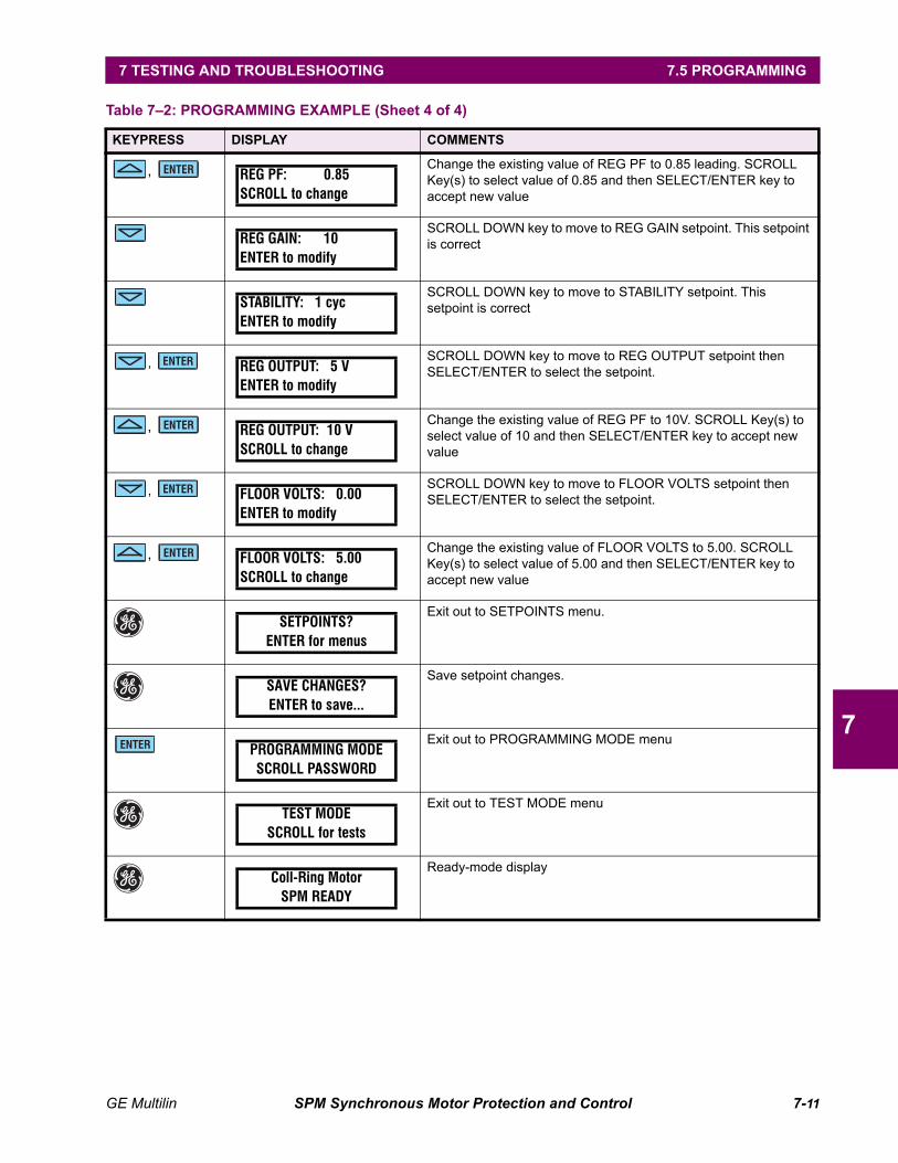
GE Multilin SPM Synchronous Motor Protection and Control 7-11
7 TESTING AND TROUBLESHOOTING 7.5 PROGRAMMING
7
, Change the existing value of REG PF to 0.85 leading. SCROLL Key(s) to select value of 0.85 and then SELECT/ENTER key to accept new value
SCROLL DOWN key to move to REG GAIN setpoint. This setpoint is correct
SCROLL DOWN key to move to STABILITY setpoint. This setpoint is correct
, SCROLL DOWN key to move to REG OUTPUT setpoint then SELECT/ENTER to select the setpoint.
, Change the existing value of REG PF to 10V. SCROLL Key(s) to select value of 10 and then SELECT/ENTER key to accept new value
, SCROLL DOWN key to move to FLOOR VOLTS setpoint then SELECT/ENTER to select the setpoint.
, Change the existing value of FLOOR VOLTS to 5.00. SCROLL Key(s) to select value of 5.00 and then SELECT/ENTER key to accept new value
Exit out to SETPOINTS menu.
Save setpoint changes.
Exit out to PROGRAMMING MODE menu
Exit out to TEST MODE menu
Ready-mode display
Table 7–2: PROGRAMMING EXAMPLE (Sheet 4 of 4)
KEYPRESS DISPLAY COMMENTS
ENTER REG PF: 0.85SCROLL to change
REG GAIN: 10ENTER to modify
STABILITY: 1 cycENTER to modify
ENTER REG OUTPUT: 5 VENTER to modify
ENTER REG OUTPUT: 10 VSCROLL to change
ENTER FLOOR VOLTS: 0.00ENTER to modify
ENTER FLOOR VOLTS: 5.00SCROLL to change
SETPOINTS?ENTER for menus
SAVE CHANGES?ENTER to save...
ENTER PROGRAMMING MODESCROLL PASSWORD
TEST MODESCROLL for tests
Coll-Ring MotorSPM READY
7-12 SPM Synchronous Motor Protection and Control GE Multilin
7.6 DOs AND DON’Ts 7 TESTING AND TROUBLESHOOTING
7
7.6 DOs AND DON’Ts 7.6.1 DOs
1. Always connect the MX input up to an auxiliary 'b' contact from the motor contactor.
It is this contact that indicates to the SPM that the motor has been started or stopped. Protection and synchro-nization routines will not run properly if this input is not connected.
2. Ensure that all ground connections are made to the ground bus.
Grounding to doors or other painted surfaces may cause the noise immunity of the SPM to be reduced.
7.6.2 DON'Ts
1. Don’t use the VDN module that was supplied with the old version MSPM (C0192) with the SPM.
The VDN module has changed and is incompatible. Damage or miss operation will occur if used.
2. Don’t use a 1A secondary CT with the SPM
The SPM has been designed to work with 5A CTs only.
3. Don’t mount the SPM display remotely.
The display must be mounted to the case when in operation. Noise problems may result if it is wired remotely.
4. Do not enable the FIELD VOLTS setpoint if the exciter is not powered up prior to starting the motor.
Field volts are monitored prior to starting and while the motor is running. A missing voltage start block will be is-sued if the SPM detects field volts less than the setpoint level while the motor is stopped and prevent starting ofthe motor.
GE Multilin SPM Synchronous Motor Protection and Control 7-13
7 TESTING AND TROUBLESHOOTING 7.7 FREQUENTLY ASKED QUESTIONS
7
7.7 FREQUENTLY ASKED QUESTIONS 7.7.1 SPM FAQ
1. Is the SPM a drop in replacement for the μSPM?
Functionally the SPM is a replacement for the older μSPM. The following points detail the differences betweenthe SPM and the μSPM when retrofitting:
• The SPM cutout size smaller. An MPSPM retrofit panel can be ordered to retrofit the SPM into existingμSPM cutouts.
• Terminal numbers have changed but terminal labels and functions remain the same.
• The VDN module has changed and the SPM must be used with the new VDN supplied with it. The CM andDCCT are the same and can be used with the SPM or μSPM.
• All μSPM options except for PF Regulation (which can be ordered) are standard on the SPM.
2. What do I do if I forget my password?
If a non-0000 password has been entered for access to programming it must be entered to gain write access.If this password has been forgotten it may be recovered in the following manner:
1. Using the GE key go to the programming section.
2. Press the scroll up key.
3. When asked to enter the password, press and hold the scroll up key and then without releasing pressand hold the enter key. While both keys are held and encrypted password will appear on the screen.
4. Record this password and contact the GE Multilin service center. They can decode the password foryou.
3. What causes a run time fault?
A run time fault is initiated by the SPM when it calculates a metered value beyond its acceptable range. Thetwo most common causes of this are:
• SPM measures a starting current higher than the programmed locked rotor current.
Solution: program LR AMPS with maximum current value seen during a start.
• SPM measures the field ohms to be beyond range of DCCT.
Solution: Turn the HIGH FIELD setpoint OFF and check calibration of DCCT and CM.
4. What is the cause of an incomplete sequence trip and how do I correct it?
An incomplete sequence trip is issued if the motor fails to synchronize in a set amount of time. Check the fol-lowing points:
• Has the INC SEQ DLY been set long enough to allow the motor to start?
• Check the VDN wiring VDN. Is it properly connected across the field discharge resistor (ring type motors)?
• Has the SYNC SLIP setting been set to the correct level (ring type motors)?
• Measure the frequency at the VF +/– terminals and ensure it falls below the programmed slip level. If not,check wiring, grounding, and the motor.
5. What is the SPM internal CT burden?
The CT burden is 16 mΩ or 0.4 VA at 1 × CT.
6. What is the power consumption to the SPM?
The SPM draws 10 VA nominal at 120 V AC.

7-14 SPM Synchronous Motor Protection and Control GE Multilin
7.7 FREQUENTLY ASKED QUESTIONS 7 TESTING AND TROUBLESHOOTING
7
7. Why do I get a long lockout time if my motor trips or fails to start?
The lockout time is variable. It is calculated to protect the motor from overheating and subsequent break-downof the amortisseur winding. This heating is caused during motor acceleration. If the lockout time is too long itcan be decreased by selecting a higher RUNTIME curve setting or by setting a longer STALL TIME. Note: Ifeither of these changes are done make sure that you have not gone beyond the motor manufacturer's specifi-cations. To avoid lockouts entirely, tripping or stopping the motor during or shortly after a start should beavoided where possible.
GE Multilin SPM Synchronous Motor Protection and Control 7-15
7 TESTING AND TROUBLESHOOTING 7.8 REVISION HISTORY
7
7.8 REVISION HISTORY 7.8.1 FIRMWARE
FIRMWARE REVISION: 109.000
• Original firmware revision for BETA test units delivered from GE Multilin in Plainville.
FIRMWARE REVISION: 151.000
• All features made standard except power factor regulation
• Check exciter field disabled while starting
• Off settings added to exciter/field voltage, current and resistance elements.
• Transient immunity improved via disabling unused inputs to processor.
FIRMWARE REVISION: 152.000
• Display now refreshed every 30 seconds
FIRMWARE REVISION: 200.000
• Modbus communications added
• Self-test changed
• Off settings made uniform
FIRMWARE REVISION: 201.000
• FAR relay not being released upon motor stopping error corrected
FIRMWARE REVISION: 202.000
• Removed runtime error on starts when measured locked rotor exceeds programmed locked rotor
• Improved communications integrated
FIRMWARE REVISION: 203.000
• The incomplete sequence function will not operate when the motor type is selected as Collector Ring.Instead a SQUIRREL CAGE TRIP is received.
FIRMWARE REVISION: 210.000
• Field Amps Loss delay added
• Field Volts Loss delay added

7-16 SPM Synchronous Motor Protection and Control GE Multilin
7.8 REVISION HISTORY 7 TESTING AND TROUBLESHOOTING
7

GE Multilin SPM Synchronous Motor Protection and Control 8-1
8 ACCESSORIES 8.1 VOLTAGE DIVIDER NETWORK
8
8 ACCESSORIES 8.1 VOLTAGE DIVIDER NETWORK 8.1.1 GE MULTILIN VDN
The VDN is provided to connect the SPM to field and/or exciter voltages. The VDN is included as a standardaccessory.
Figure 8–1: GE MULTILIN VOLTAGE DIVIDER NETWORK
Figure 8–2: GE MULTILIN VDN DIMENSIONS
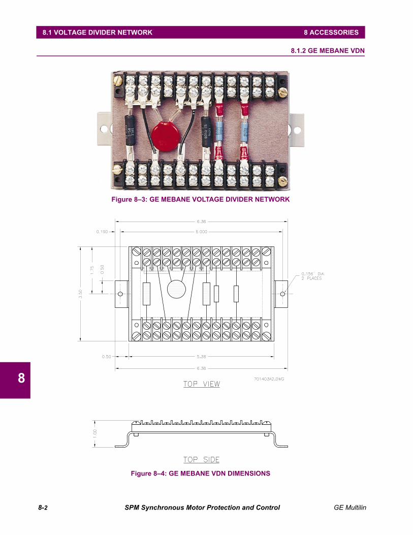
8-2 SPM Synchronous Motor Protection and Control GE Multilin
8.1 VOLTAGE DIVIDER NETWORK 8 ACCESSORIES
8
8.1.2 GE MEBANE VDN
Figure 8–3: GE MEBANE VOLTAGE DIVIDER NETWORK
Figure 8–4: GE MEBANE VDN DIMENSIONS
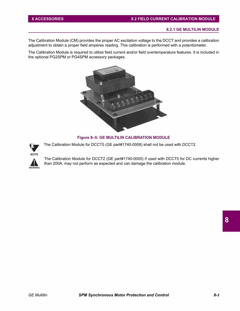
GE Multilin SPM Synchronous Motor Protection and Control 8-3
8 ACCESSORIES 8.2 FIELD CURRENT CALIBRATION MODULE
8
8.2 FIELD CURRENT CALIBRATION MODULE 8.2.1 GE MULTILIN MODULE
The Calibration Module (CM) provides the proper AC excitation voltage to the DCCT and provides a calibrationadjustment to obtain a proper field amperes reading. This calibration is performed with a potentiometer.
The Calibration Module is required to utilize field current and/or field overtemperature features. It is included inthe optional PG2SPM or PG4SPM accessory packages.
Figure 8–5: GE MULTILIN CALIBRATION MODULE
The Calibration Module for DCCT5 (GE part#1740-0008) shall not be used with DCCT2.
The Calibration Module for DCCT2 (GE part#1740-0005) if used with DCCT5 for DC currents higherthan 200A, may not perform as expected and can damage the calibration module.
NOTE
WARNING
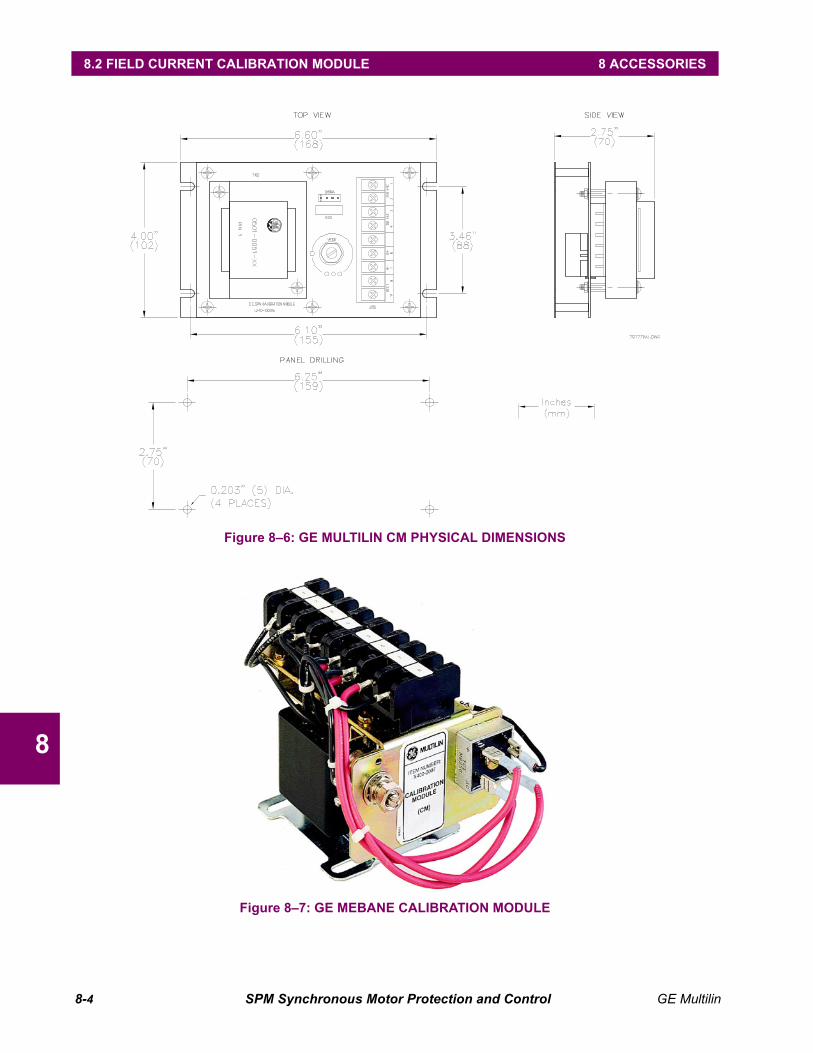
8-4 SPM Synchronous Motor Protection and Control GE Multilin
8.2 FIELD CURRENT CALIBRATION MODULE 8 ACCESSORIES
8
Figure 8–6: GE MULTILIN CM PHYSICAL DIMENSIONS
Figure 8–7: GE MEBANE CALIBRATION MODULE
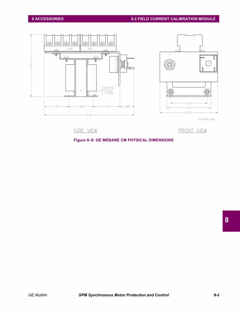
GE Multilin SPM Synchronous Motor Protection and Control 8-5
8 ACCESSORIES 8.2 FIELD CURRENT CALIBRATION MODULE
8
Figure 8–8: GE MEBANE CM PHYSICAL DIMENSIONS
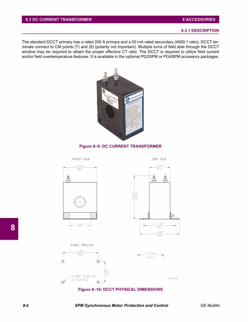
8-6 SPM Synchronous Motor Protection and Control GE Multilin
8.3 DC CURRENT TRANSFORMER 8 ACCESSORIES
8
8.3 DC CURRENT TRANSFORMER 8.3.1 DESCRIPTION
The standard DCCT primary has a rated 200 A primary and a 50 mA rated secondary (4000:1 ratio). DCCT ter-minals connect to CM points (7) and (8) (polarity not important). Multiple turns of field able through the DCCTwindow may be required to obtain the proper effective CT ratio. The DCCT is required to utilize field currentand/or field overtemperature features. It is available in the optional PG2SPM or PG4SPM accessory packages.
Figure 8–9: DC CURRENT TRANSFORMER
Figure 8–10: DCCT PHYSICAL DIMENSIONS
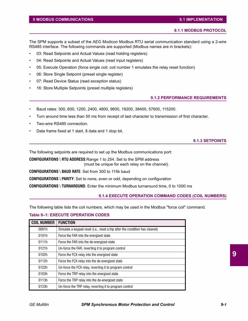
GE Multilin SPM Synchronous Motor Protection and Control 9-1
9 MODBUS COMMUNICATIONS 9.1 IMPLEMENTATION
9
9 MODBUS COMMUNICATIONS 9.1 IMPLEMENTATION 9.1.1 MODBUS PROTOCOL
The SPM supports a subset of the AEG Modicon Modbus RTU serial communication standard using a 2-wireRS485 interface. The following commands are supported (Modbus names are in brackets):
• 03: Read Setpoints and Actual Values (read holding registers)
• 04: Read Setpoints and Actual Values (read input registers)
• 05: Execute Operation (force single coil; coil number 1 emulates the relay reset function)
• 06: Store Single Setpoint (preset single register)
• 07: Read Device Status (read exception status)
• 16: Store Multiple Setpoints (preset multiple registers)
9.1.2 PERFORMANCE REQUIREMENTS
• Baud rates: 300, 600, 1200, 2400, 4800, 9600, 19200, 38400, 57600, 115200.
• Turn around time less than 50 ms from receipt of last character to transmission of first character.
• Two-wire RS485 connection.
• Data frame fixed at 1 start, 8 data and 1 stop bit.
9.1.3 SETPOINTS
The following setpoints are required to set up the Modbus communications port:
CONFIGURATIONS \ RTU ADDRESS:Range 1 to 254. Set to the SPM address(must be unique for each relay on the channel).
CONFIGURATIONS \ BAUD RATE: Set from 300 to 115k baud
CONFIGURATIONS \ PARITY: Set to none, even or odd, depending on configuration
CONFIGURATIONS \ TURNAROUND: Enter the minimum Modbus turnaround time, 0 to 1000 ms
9.1.4 EXECUTE OPERATION COMMAND CODES (COIL NUMBERS)
The following table lists the coil numbers, which may be used in the Modbus "force coil" command.
Table 9–1: EXECUTE OPERATION CODES
COIL NUMBER FUNCTION
0001h Simulate a keypad reset (i.e., reset a trip after the condition has cleared)
0101h Force the FAR into the energized state
0111h Force the FAR into the de-energized state
0121h Un-force the FAR, reverting it to program control
0102h Force the FCX relay into the energized state
0112h Force the FCX relay into the de-energized state
0122h Un-force the FCX relay, reverting it to program control
0103h Force the TRP relay into the energized state
0113h Force the TRP relay into the de-energized state
0123h Un-force the TRP relay, reverting it to program control
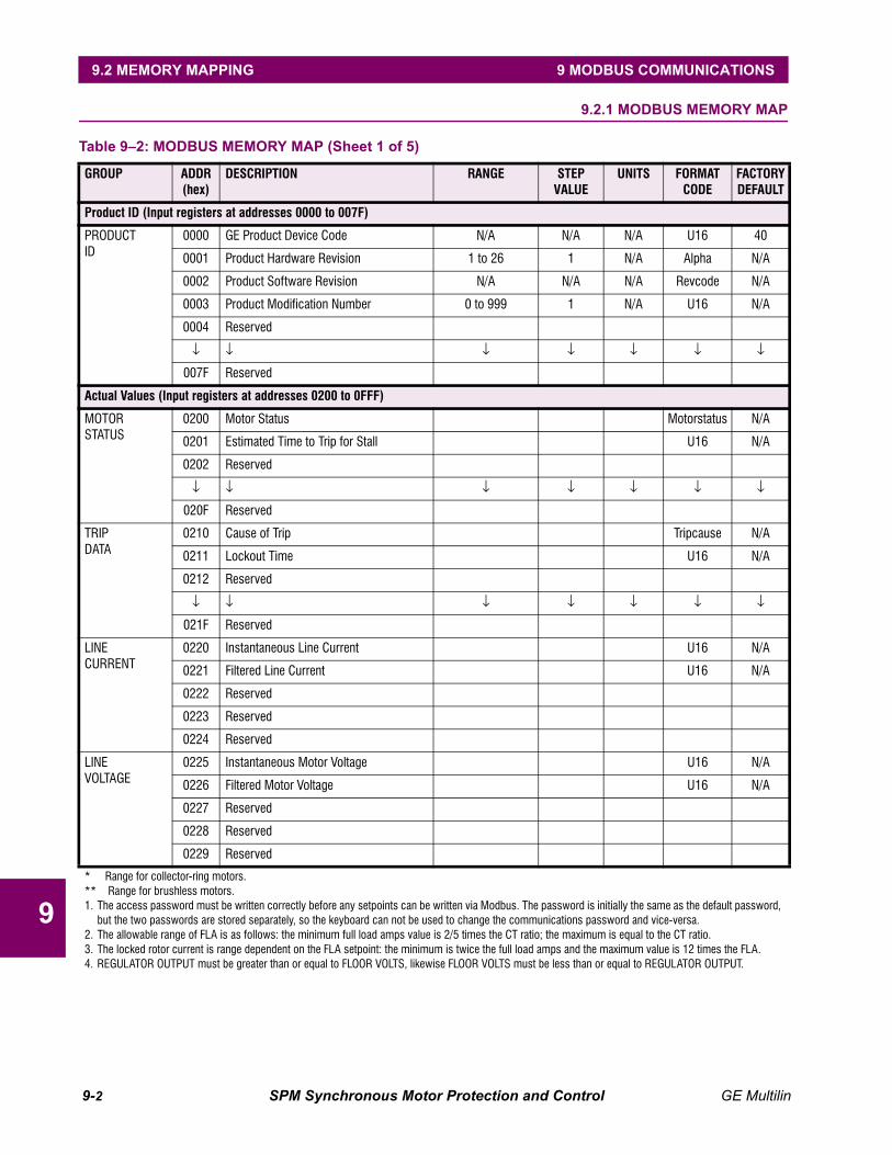
9-2 SPM Synchronous Motor Protection and Control GE Multilin
9.2 MEMORY MAPPING 9 MODBUS COMMUNICATIONS
9
9.2 MEMORY MAPPING 9.2.1 MODBUS MEMORY MAP
Table 9–2: MODBUS MEMORY MAP (Sheet 1 of 5)
GROUP ADDR (hex)
DESCRIPTION RANGE STEP VALUE
UNITS FORMAT CODE
FACTORY DEFAULT
Product ID (Input registers at addresses 0000 to 007F)
PRODUCTID
0000 GE Product Device Code N/A N/A N/A U16 40
0001 Product Hardware Revision 1 to 26 1 N/A Alpha N/A
0002 Product Software Revision N/A N/A N/A Revcode N/A
0003 Product Modification Number 0 to 999 1 N/A U16 N/A
0004 Reserved
↓ ↓ ↓ ↓ ↓ ↓ ↓
007F Reserved
Actual Values (Input registers at addresses 0200 to 0FFF)
MOTORSTATUS
0200 Motor Status Motorstatus N/A
0201 Estimated Time to Trip for Stall U16 N/A
0202 Reserved
↓ ↓ ↓ ↓ ↓ ↓ ↓
020F Reserved
TRIPDATA
0210 Cause of Trip Tripcause N/A
0211 Lockout Time U16 N/A
0212 Reserved
↓ ↓ ↓ ↓ ↓ ↓ ↓
021F Reserved
LINECURRENT
0220 Instantaneous Line Current U16 N/A
0221 Filtered Line Current U16 N/A
0222 Reserved
0223 Reserved
0224 Reserved
LINEVOLTAGE
0225 Instantaneous Motor Voltage U16 N/A
0226 Filtered Motor Voltage U16 N/A
0227 Reserved
0228 Reserved
0229 Reserved
* Range for collector-ring motors.** Range for brushless motors.1. The access password must be written correctly before any setpoints can be written via Modbus. The password is initially the same as the default password,
but the two passwords are stored separately, so the keyboard can not be used to change the communications password and vice-versa.2. The allowable range of FLA is as follows: the minimum full load amps value is 2/5 times the CT ratio; the maximum is equal to the CT ratio.3. The locked rotor current is range dependent on the FLA setpoint: the minimum is twice the full load amps and the maximum value is 12 times the FLA.4. REGULATOR OUTPUT must be greater than or equal to FLOOR VOLTS, likewise FLOOR VOLTS must be less than or equal to REGULATOR OUTPUT.
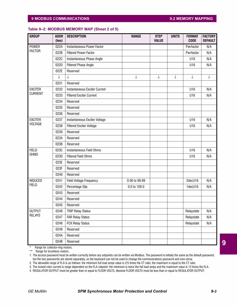
GE Multilin SPM Synchronous Motor Protection and Control 9-3
9 MODBUS COMMUNICATIONS 9.2 MEMORY MAPPING
9
POWERFACTOR
022A Instantaneous Power Factor Pwrfactor N/A
022B Filtered Power Factor Pwrfactor N/A
022C Instantaneous Phase Angle U16 N/A
022D Filtered Phase Angle U16 N/A
022E Reserved
↓ ↓ ↓ ↓ ↓ ↓ ↓
0231 Reserved
EXCITERCURRENT
0232 Instantaneous Exciter Current U16 N/A
0233 Filtered Exciter Current U16 N/A
0234 Reserved
0235 Reserved
0236 Reserved
EXCITERVOLTAGE
0237 Instantaneous Exciter Voltage U16 N/A
0238 Filtered Exciter Voltage U16 N/A
0239 Reserved
023A Reserved
023B Reserved
FIELDOHMS
023C Instantaneous Field Ohms U16 N/A
023D Filtered Field Ohms U16 N/A
023E Reserved
023F Reserved
0240 Reserved
INDUCEDFIELD
0241 Field Voltage Frequency 0.00 to 99.99 2decU16 N/A
0242 Percentage Slip 0.0 to 100.0 1decU16 N/A
0243 Reserved
0244 Reserved
0245 Reserved
OUTPUTRELAYS
0246 TRIP Relay Status Relaystate N/A
0247 FAR Relay Status Relaystate N/A
0248 FCX Relay Status Relaystate N/A
0249 Reserved
024A Reserved
024B Reserved
Table 9–2: MODBUS MEMORY MAP (Sheet 2 of 5)
GROUP ADDR (hex)
DESCRIPTION RANGE STEP VALUE
UNITS FORMAT CODE
FACTORY DEFAULT
* Range for collector-ring motors.** Range for brushless motors.1. The access password must be written correctly before any setpoints can be written via Modbus. The password is initially the same as the default password,
but the two passwords are stored separately, so the keyboard can not be used to change the communications password and vice-versa.2. The allowable range of FLA is as follows: the minimum full load amps value is 2/5 times the CT ratio; the maximum is equal to the CT ratio.3. The locked rotor current is range dependent on the FLA setpoint: the minimum is twice the full load amps and the maximum value is 12 times the FLA.4. REGULATOR OUTPUT must be greater than or equal to FLOOR VOLTS, likewise FLOOR VOLTS must be less than or equal to REGULATOR OUTPUT.

9-4 SPM Synchronous Motor Protection and Control GE Multilin
9.2 MEMORY MAPPING 9 MODBUS COMMUNICATIONS
9
DIGITALINPUTS
024C MX Status Switchstate N/A
024D NX Status Switchstate N/A
024E Reserved
↓ ↓ ↓ ↓ ↓ ↓ ↓
0254 Reserved
STATISTICS(can be written as holding registers)
0255 Motor Running Hours U16 N/A
0256 Incomplete Sequence Trip Counter U16 N/A
0257 Field Loss Trip Counter U16 N/A
0258 Pull Out Trip Counter U16 N/A
0259 Resynchronization Trip Counter U16 N/A
025A Missing External PF Voltage Reference U16 N/A
025B Check Exciter Trip Counter U16 N/A
025C Power Factor Trip Counter U16 N/A
025D Squirrel Cage Trip Counter U16 N/A
025E Field Overtemperature Trip Counter U16 N/A
025F Reserved
↓ ↓ ↓ ↓ ↓ ↓ ↓
0FFF Reserved
Setpoints (Holding registers at addresses 1000 to 2FFF)
SYSTEM CONFIGURATION
1000 ACCESS PASSWORD 1 0 to 9999 1 - U16 0000
1001 MOTOR TYPE 0 or 1 - - Motortype 0
1002 LINE FREQUENCY 0 or 1 - Hz Linefreq 0
1003 POWER FACTOR REFERENCE 0 or 1 - - PFreg 1
1004 RTU ADDRESS 1 to 254 1 - U16 1
1005 BAUD RATE 0 to 9 1 baud Baudrate 6
1006 RS485 PARITY 0 to 2 1 Parity 0
1007 RS485 MIN. TURNAROUND TIME 0 1000 ms U16 5
1008 STATISTICS MODE 0 or 1 1 - Startmode 1
1009 NEW PASSWORD 0 to 9999 1 - U16 4985
1010 Reserved
↓ ↓ ↓ ↓ ↓ ↓ ↓
104F Reserved
Table 9–2: MODBUS MEMORY MAP (Sheet 3 of 5)
GROUP ADDR (hex)
DESCRIPTION RANGE STEP VALUE
UNITS FORMAT CODE
FACTORY DEFAULT
* Range for collector-ring motors.** Range for brushless motors.1. The access password must be written correctly before any setpoints can be written via Modbus. The password is initially the same as the default password,
but the two passwords are stored separately, so the keyboard can not be used to change the communications password and vice-versa.2. The allowable range of FLA is as follows: the minimum full load amps value is 2/5 times the CT ratio; the maximum is equal to the CT ratio.3. The locked rotor current is range dependent on the FLA setpoint: the minimum is twice the full load amps and the maximum value is 12 times the FLA.4. REGULATOR OUTPUT must be greater than or equal to FLOOR VOLTS, likewise FLOOR VOLTS must be less than or equal to REGULATOR OUTPUT.
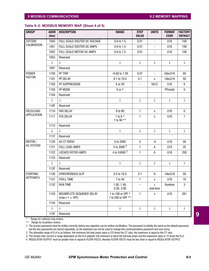
GE Multilin SPM Synchronous Motor Protection and Control 9-5
9 MODBUS COMMUNICATIONS 9.2 MEMORY MAPPING
9
SYSTEM CALIBRATION
1050 FULL SCALE EXCITER DC VOLTAGE 0.6 to 1.5 0.01 - U16 100
1051 FULL SCALE EXCITER DC AMPS 0.6 to 1.5 0.01 - U16 100
1052 FULL SCALE MOTOR AC AMPS 0.6 to 1.5 0.01 - U16 100
1053 Reserved
↓ ↓ ↓ ↓ ↓ ↓ ↓
10FF Reserved
POWER FACTOR
1100 PF TRIP –0.60 to 1.00 0.01 - 2decS16 60
1101 PF DELAY 0.1 to 10.0 0.1 s 1decU16 50
1102 PF SUPPRESSION 6 or 50 - %FLC U16 6
1103 PF MODE 0 or 1 PFmode 0
1104 Reserved
↓ ↓ ↓ ↓ ↓ ↓ ↓
110F Reserved
FIELD/LOADAPPLICATION
1110 FAR DELAY 0 to 90 1 s U16 0
1111 FCX DELAY 1 to 6 *1 to 90 **
1 s U16 1
1112 Reserved
↓ ↓ ↓ ↓ ↓ ↓ ↓
111F Reserved
MOTOR /AC SYSTEM
1120 AC CT RATIO 5 to 2000 5 :5 U16 50
1121 FULL LOAD AMPS 2 to 2000 2 1 A U16 25
1122 LOCKED ROTOR AMPS 4 to 24000 3 1 A U16 200
1123 Reserved
↓ ↓ ↓ ↓ ↓ ↓ ↓
112F Reserved
STARTING SETPOINTS
1130 SYNCHRONOUS SLIP 0.5 to 10.0 0.1 % 1decU16 50
1131 STALL TIME 1 to 40 1 s U16 10
1132 RUN TIME 1.05, 1.46,2.05, 3.00
- × stall time
Runtime 3
1133 INCOMPLETE SEQUENCE DELAY(max+1 = OFF)
1 to 100 or OFF *1 to 200 or OFF **
1 s U16 201
1134 Reserved
↓ ↓ ↓ ↓ ↓ ↓ ↓
113F Reserved
Table 9–2: MODBUS MEMORY MAP (Sheet 4 of 5)
GROUP ADDR (hex)
DESCRIPTION RANGE STEP VALUE
UNITS FORMAT CODE
FACTORY DEFAULT
* Range for collector-ring motors.** Range for brushless motors.1. The access password must be written correctly before any setpoints can be written via Modbus. The password is initially the same as the default password,
but the two passwords are stored separately, so the keyboard can not be used to change the communications password and vice-versa.2. The allowable range of FLA is as follows: the minimum full load amps value is 2/5 times the CT ratio; the maximum is equal to the CT ratio.3. The locked rotor current is range dependent on the FLA setpoint: the minimum is twice the full load amps and the maximum value is 12 times the FLA.4. REGULATOR OUTPUT must be greater than or equal to FLOOR VOLTS, likewise FLOOR VOLTS must be less than or equal to REGULATOR OUTPUT.
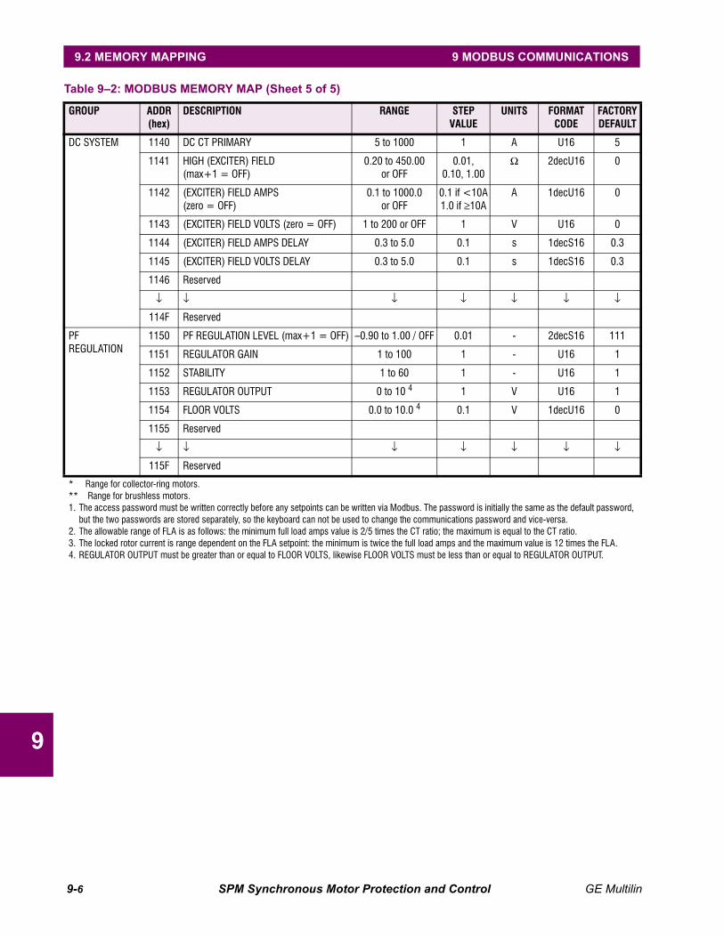
9-6 SPM Synchronous Motor Protection and Control GE Multilin
9.2 MEMORY MAPPING 9 MODBUS COMMUNICATIONS
9
DC SYSTEM 1140 DC CT PRIMARY 5 to 1000 1 A U16 5
1141 HIGH (EXCITER) FIELD(max+1 = OFF)
0.20 to 450.00or OFF
0.01, 0.10, 1.00
Ω 2decU16 0
1142 (EXCITER) FIELD AMPS(zero = OFF)
0.1 to 1000.0or OFF
0.1 if <10A1.0 if ≥10A
A 1decU16 0
1143 (EXCITER) FIELD VOLTS (zero = OFF) 1 to 200 or OFF 1 V U16 0
1144 (EXCITER) FIELD AMPS DELAY 0.3 to 5.0 0.1 s 1decS16 0.3
1145 (EXCITER) FIELD VOLTS DELAY 0.3 to 5.0 0.1 s 1decS16 0.3
1146 Reserved
↓ ↓ ↓ ↓ ↓ ↓ ↓
114F Reserved
PF REGULATION
1150 PF REGULATION LEVEL (max+1 = OFF) –0.90 to 1.00 / OFF 0.01 - 2decS16 111
1151 REGULATOR GAIN 1 to 100 1 - U16 1
1152 STABILITY 1 to 60 1 - U16 1
1153 REGULATOR OUTPUT 0 to 10 4 1 V U16 1
1154 FLOOR VOLTS 0.0 to 10.0 4 0.1 V 1decU16 0
1155 Reserved
↓ ↓ ↓ ↓ ↓ ↓ ↓
115F Reserved
Table 9–2: MODBUS MEMORY MAP (Sheet 5 of 5)
GROUP ADDR (hex)
DESCRIPTION RANGE STEP VALUE
UNITS FORMAT CODE
FACTORY DEFAULT
* Range for collector-ring motors.** Range for brushless motors.1. The access password must be written correctly before any setpoints can be written via Modbus. The password is initially the same as the default password,
but the two passwords are stored separately, so the keyboard can not be used to change the communications password and vice-versa.2. The allowable range of FLA is as follows: the minimum full load amps value is 2/5 times the CT ratio; the maximum is equal to the CT ratio.3. The locked rotor current is range dependent on the FLA setpoint: the minimum is twice the full load amps and the maximum value is 12 times the FLA.4. REGULATOR OUTPUT must be greater than or equal to FLOOR VOLTS, likewise FLOOR VOLTS must be less than or equal to REGULATOR OUTPUT.
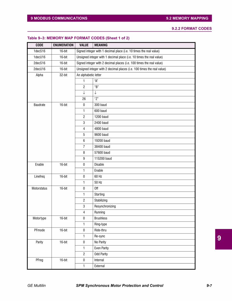
GE Multilin SPM Synchronous Motor Protection and Control 9-7
9 MODBUS COMMUNICATIONS 9.2 MEMORY MAPPING
9
9.2.2 FORMAT CODES
Table 9–3: MEMORY MAP FORMAT CODES (Sheet 1 of 2)
CODE ENUMERATION VALUE MEANING
1decS16 16-bit Signed integer with 1 decimal place (i.e. 10 times the real value)
1decU16 16-bit Unsigned integer with 1 decimal place (i.e. 10 times the real value)
2decS16 16-bit Signed integer with 2 decimal places (i.e. 100 times the real value)
2decU16 16-bit Unsigned integer with 2 decimal places (i.e. 100 times the real value)
Alpha 32-bit An alphabetic letter
1 “A”
2 “B”
↓ ↓
26 “Z”
Baudrate 16-bit 0 300 baud
1 600 baud
2 1200 baud
3 2400 baud
4 4800 baud
5 9600 baud
6 19200 baud
7 38400 baud
8 57600 baud
9 115200 baud
Enable 16-bit 0 Disable
1 Enable
Linefreq 16-bit 0 60 Hz
1 50 Hz
Motorstatus 16-bit 0 Off
1 Starting
2 Stabilizing
3 Resynchronizing
4 Running
Motortype 16-bit 0 Brushless
1 Ring-type
PFmode 16-bit 0 Ride-thru
1 Re-sync
Parity 16-bit 0 No Parity
1 Even Parity
2 Odd Parity
PFreg 16-bit 0 Internal
1 External
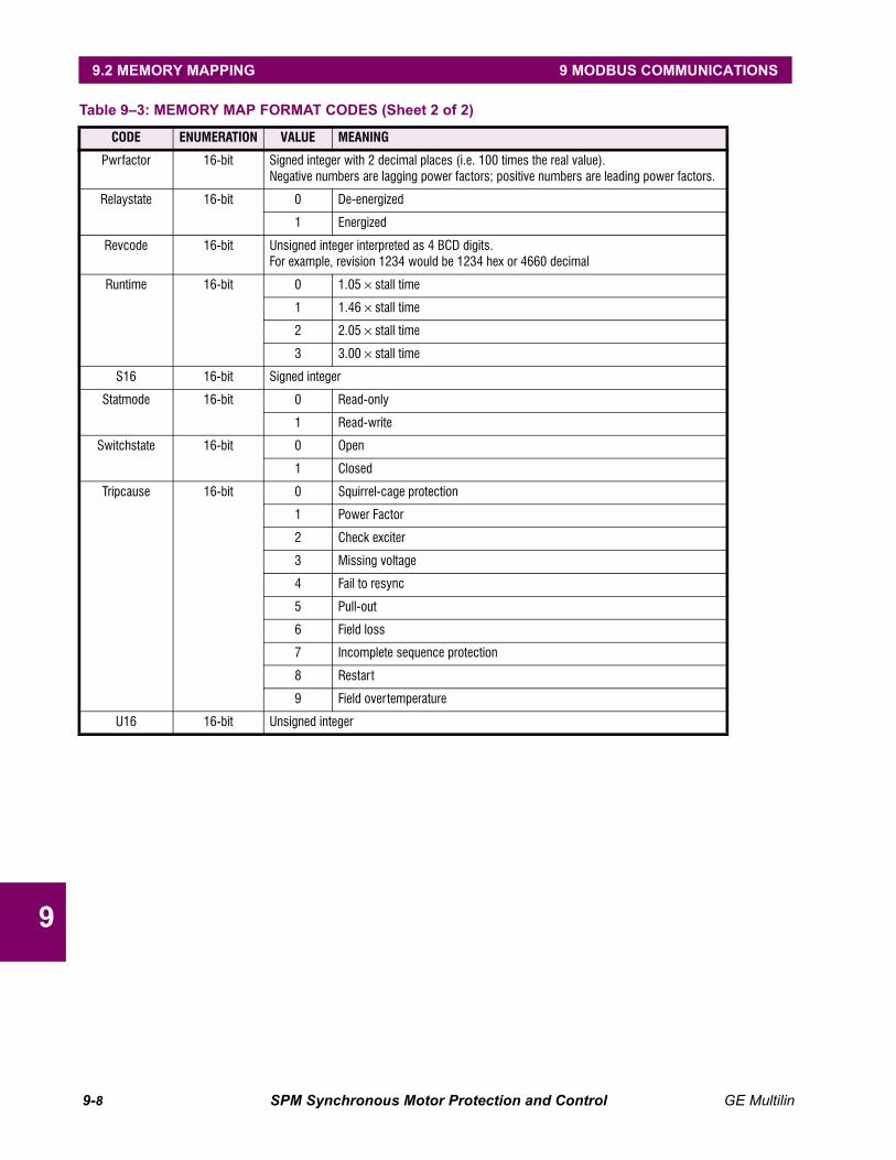
9-8 SPM Synchronous Motor Protection and Control GE Multilin
9.2 MEMORY MAPPING 9 MODBUS COMMUNICATIONS
9
Pwrfactor 16-bit Signed integer with 2 decimal places (i.e. 100 times the real value).Negative numbers are lagging power factors; positive numbers are leading power factors.
Relaystate 16-bit 0 De-energized
1 Energized
Revcode 16-bit Unsigned integer interpreted as 4 BCD digits.For example, revision 1234 would be 1234 hex or 4660 decimal
Runtime 16-bit 0 1.05 × stall time
1 1.46 × stall time
2 2.05 × stall time
3 3.00 × stall time
S16 16-bit Signed integer
Statmode 16-bit 0 Read-only
1 Read-write
Switchstate 16-bit 0 Open
1 Closed
Tripcause 16-bit 0 Squirrel-cage protection
1 Power Factor
2 Check exciter
3 Missing voltage
4 Fail to resync
5 Pull-out
6 Field loss
7 Incomplete sequence protection
8 Restart
9 Field overtemperature
U16 16-bit Unsigned integer
Table 9–3: MEMORY MAP FORMAT CODES (Sheet 2 of 2)
CODE ENUMERATION VALUE MEANING
GE Multilin SPM Synchronous Motor Protection and Control 10-1
10 FUNCTIONAL TESTS 10.1 INTRODUCTION
1010 FUNCTIONAL TESTS 10.1 INTRODUCTION 10.1.1 DESCRIPTION
The purpose of this section is to demonstrate the procedures necessary to perform a complete functional testof all the SPM hardware while also testing firmware/hardware interaction in the process. Since the SPM ispackaged in a drawout case, a demo case (metal carry case in which an SPM may be mounted) may be usefulfor creating a portable test set with a wiring harness for all of the I/O. Testing of the relay during commissioningusing a primary injection test set will ensure that CTs and wiring are correct and complete.
Cycle power to SPM to clear lockout times that may occur during testing.
After testing is complete it is a good idea to zero all statistics.
The following equipment is recommended to test the SPM's functionality and calibration.
1. 3 phase variable ac test set (voltage and current)
2. 0 to 15 V DC voltage source (needed to test Exciter/Field volts or current inputs)
3. Function generator (needed to test collector ring field application)
4. Timer
5. Multimeters
6. Switch
NOTE
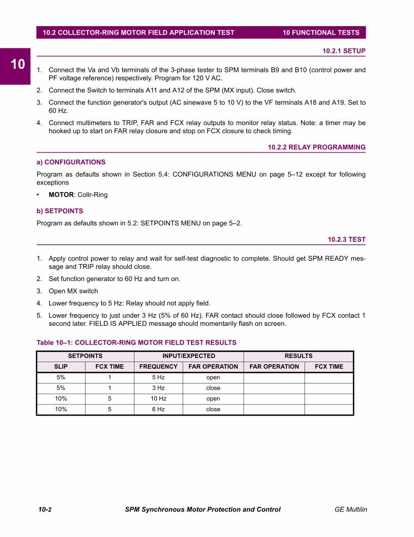
10-2 SPM Synchronous Motor Protection and Control GE Multilin
10.2 COLLECTOR-RING MOTOR FIELD APPLICATION TEST 10 FUNCTIONAL TESTS
1010.2 COLLECTOR-RING MOTOR FIELD APPLICATION TEST 10.2.1 SETUP
1. Connect the Va and Vb terminals of the 3-phase tester to SPM terminals B9 and B10 (control power andPF voltage reference) respectively. Program for 120 V AC.
2. Connect the Switch to terminals A11 and A12 of the SPM (MX input). Close switch.
3. Connect the function generator's output (AC sinewave 5 to 10 V) to the VF terminals A18 and A19. Set to60 Hz.
4. Connect multimeters to TRIP, FAR and FCX relay outputs to monitor relay status. Note: a timer may behooked up to start on FAR relay closure and stop on FCX closure to check timing.
10.2.2 RELAY PROGRAMMING
a) CONFIGURATIONS
Program as defaults shown in Section 5.4: CONFIGURATIONS MENU on page 5–12 except for followingexceptions
• MOTOR: Collr-Ring
b) SETPOINTS
Program as defaults shown in 5.2: SETPOINTS MENU on page 5–2.
10.2.3 TEST
1. Apply control power to relay and wait for self-test diagnostic to complete. Should get SPM READY mes-sage and TRIP relay should close.
2. Set function generator to 60 Hz and turn on.
3. Open MX switch
4. Lower frequency to 5 Hz: Relay should not apply field.
5. Lower frequency to just under 3 Hz (5% of 60 Hz). FAR contact should close followed by FCX contact 1second later. FIELD IS APPLIED message should momentarily flash on screen.
Table 10–1: COLLECTOR-RING MOTOR FIELD TEST RESULTS
SETPOINTS INPUT/EXPECTED RESULTS
SLIP FCX TIME FREQUENCY FAR OPERATION FAR OPERATION FCX TIME
5% 1 5 Hz open
5% 1 3 Hz close
10% 5 10 Hz open
10% 5 6 Hz close

GE Multilin SPM Synchronous Motor Protection and Control 10-3
10 FUNCTIONAL TESTS 10.3 COLLECTOR-RING MOTOR POWER FACTOR TEST
1010.3 COLLECTOR-RING MOTOR POWER FACTOR TEST 10.3.1 SETUP
1. Connect the Va and Vb terminals of the 3-phase tester to SPM terminals B9 and B10 (control power andPF voltage reference) respectively. Program for 120 V AC. To test the OPTIONAL PF REFERENCE inputconnect Va and Vb to terminals A4 and A5 and 120 V AC to B9 and B10.
2. Connect Ic of the 3-phase tester terminals B3 and B4. Polarity is critical. Note: Ia and Ib outputs of 3qtester may have to be shorted if they cannot be turned off. Program for 4A.
3. Connect the function generator's output (AC sinewave 5 to 10 V) to the VF terminals A18 and A19. Set to3 Hz.
4. Connect the Switch to terminals A11 and A12 of the SPM (MX input). Close switch.
5. Connect multimeter to TRIP relay outputs to monitor relay status.
10.3.2 RELAY PROGRAMMING
a) CONFIGURATIONS
Program as defaults shown in Section 5.4: CONFIGURATIONS MENU on page 5–12 except for followingexceptions
• MOTOR: Collector-Ring
• PF REF: External (if testing the external PF volt-age reference)
b) SETPOINTS
Program as defaults shown in 5.2: SETPOINTS MENU on page 5–2.
10.3.3 TEST
1. Apply control power to relay and wait for self-test diagnostic to complete. Should get SPM READY mes-sage and TRIP relay should close.
2. Turn on current source and function generator.
3. Open MX switch
4. FAR contact should close followed by FCX contact. FIELD IS APPLIED message should momentarily flashon screen.
5. PF metered value will now be displayed along with other metered values.
6. Vary voltage angle as in table below and check PF reading.
Table 10–2: COLLECTOR-RING MOTOR PF TEST RESULTS
ANGLE EXPECTED PF ACTUAL PF
0° 1
25° 0.9
65° 0.4
317° –0.74
341° –0.95

10-4 SPM Synchronous Motor Protection and Control GE Multilin
10.4 COLLECTOR-RING MOTOR POWER FACTOR TRIP TEST 10 FUNCTIONAL TESTS
1010.4 COLLECTOR-RING MOTOR POWER FACTOR TRIP TEST 10.4.1 SETUP
1. Connect as for Collector-Ring Power Factor Test in the previous section.
2. Connect timer to TRIP relay.
10.4.2 RELAY PROGRAMMING
a) CONFIGURATIONS
Program as defaults shown in Section 5.4: CONFIGURATIONS MENU on page 5–12 except for followingexceptions
• MOTOR: Collector-Ring
b) SETPOINTS
Program as defaults shown in 5.2: SETPOINTS MENU on page 5–2.
10.4.3 TEST
1. Apply control power to relay and wait for self test diagnostic to complete. Should get SPM READY mes-sage and TRIP relay should close.
2. Turn on current source and function generator.
3. Open MX switch
4. FAR contact should close followed by FCX contact. FIELD IS APPLIED message should momentarily flashon screen.
5. PF metered value will now be displayed along with other metered values.
6. Vary voltage angle as in table below and check PF reading.
Table 10–3: COLLECTOR-RING MOTOR PF TRIP TEST RESULTS
SETPOINTS INPUT/EXPECTED RESULTS
PF TRIP PF DELAY ANGLE EXPECTED PF TRIP TIME
–0.60 1 302° –0.52
–0.70 5 309° –0.63
–0.80 3 317° –0.74
1.00 10 341° –0.95
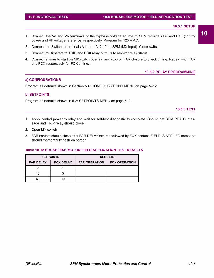
GE Multilin SPM Synchronous Motor Protection and Control 10-5
10 FUNCTIONAL TESTS 10.5 BRUSHLESS MOTOR FIELD APPLICATION TEST
1010.5 BRUSHLESS MOTOR FIELD APPLICATION TEST 10.5.1 SETUP
1. Connect the Va and Vb terminals of the 3-phase voltage source to SPM terminals B9 and B10 (controlpower and PF voltage reference) respectively. Program for 120 V AC.
2. Connect the Switch to terminals A11 and A12 of the SPM (MX input). Close switch.
3. Connect multimeters to TRIP and FCX relay outputs to monitor relay status.
4. Connect a timer to start on MX switch opening and stop on FAR closure to check timing. Repeat with FARand FCX respectively for FCX timing.
10.5.2 RELAY PROGRAMMING
a) CONFIGURATIONS
Program as defaults shown in Section 5.4: CONFIGURATIONS MENU on page 5–12.
b) SETPOINTS
Program as defaults shown in 5.2: SETPOINTS MENU on page 5–2.
10.5.3 TEST
1. Apply control power to relay and wait for self-test diagnostic to complete. Should get SPM READY mes-sage and TRIP relay should close.
2. Open MX switch
3. FAR contact should close after FAR DELAY expires followed by FCX contact. FIELD IS APPLIED messageshould momentarily flash on screen.
Table 10–4: BRUSHLESS MOTOR FIELD APPLICATION TEST RESULTS
SETPOINTS RESULTS
FAR DELAY FCX DELAY FAR OPERATION FCX OPERATION
0 1
10 5
60 10

10-6 SPM Synchronous Motor Protection and Control GE Multilin
10.6 BRUSHLESS MOTOR POWER FACTOR TEST 10 FUNCTIONAL TESTS
1010.6 BRUSHLESS MOTOR POWER FACTOR TEST 10.6.1 SETUP
1. Connect the Va and Vb terminals of the 3-phase tester to SPM terminals B9 and B10 (control power andPF voltage reference) respectively. Program for 120 V AC. To test the OPTIONAL PF REFERENCE inputconnect Va and Vb to terminals A4 and A5 and 120VAC to B9 and B10.
2. Connect Ia of the 3-phase tester terminals B3 and B4 and Ib to terminals B1 and B2. Polarity is critical.Note: Ic outputs of 3-phase tester may have to be shorted if they cannot be turned off. Program for 4 A.
3. Connect the Switch to terminals A11 and A12 of the SPM (MX input). Close switch.
4. Connect multimeter to TRIP relay outputs to monitor relay status.
10.6.2 RELAY PROGRAMMING
a) CONFIGURATIONS
Program as defaults shown in Section 5.4: CONFIGURATIONS MENU on page 5–12 except for the following:
• PF REF: External (if testing the external PF voltage reference)
b) SETPOINTS
Program as defaults shown in 5.2: SETPOINTS MENU on page 5–2.
10.6.3 TEST
1. Apply control power to relay and wait for self-test diagnostic to complete. Should get SPM READY mes-sage and TRIP relay should close.
2. Turn on current source.
3. Open MX switch
4. FAR contact should close after programmed delay followed by FCX contact. FIELD IS APPLIED messageshould momentarily flash on screen.
5. PF metered value will now be displayed along with other metered values.
6. Vary voltage angle as in table below and check PF reading.
Table 10–5: BRUSHLESS MOTOR PF TEST RESULTS
ANGLE EXPECTED PF ACTUAL PF
0° 1
25° 0.9
65° 0.4
317° –0.74
341° –0.95
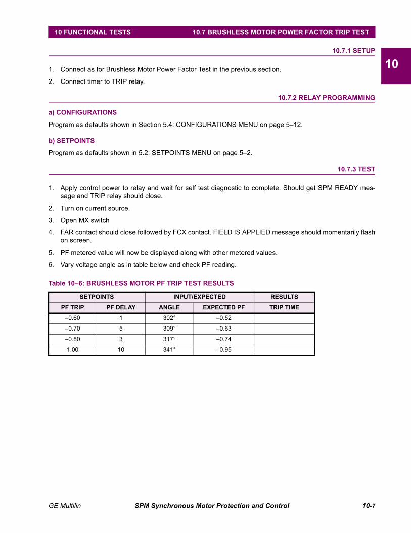
GE Multilin SPM Synchronous Motor Protection and Control 10-7
10 FUNCTIONAL TESTS 10.7 BRUSHLESS MOTOR POWER FACTOR TRIP TEST
1010.7 BRUSHLESS MOTOR POWER FACTOR TRIP TEST 10.7.1 SETUP
1. Connect as for Brushless Motor Power Factor Test in the previous section.
2. Connect timer to TRIP relay.
10.7.2 RELAY PROGRAMMING
a) CONFIGURATIONS
Program as defaults shown in Section 5.4: CONFIGURATIONS MENU on page 5–12.
b) SETPOINTS
Program as defaults shown in 5.2: SETPOINTS MENU on page 5–2.
10.7.3 TEST
1. Apply control power to relay and wait for self test diagnostic to complete. Should get SPM READY mes-sage and TRIP relay should close.
2. Turn on current source.
3. Open MX switch
4. FAR contact should close followed by FCX contact. FIELD IS APPLIED message should momentarily flashon screen.
5. PF metered value will now be displayed along with other metered values.
6. Vary voltage angle as in table below and check PF reading.
Table 10–6: BRUSHLESS MOTOR PF TRIP TEST RESULTS
SETPOINTS INPUT/EXPECTED RESULTS
PF TRIP PF DELAY ANGLE EXPECTED PF TRIP TIME
–0.60 1 302° –0.52
–0.70 5 309° –0.63
–0.80 3 317° –0.74
1.00 10 341° –0.95

10-8 SPM Synchronous Motor Protection and Control GE Multilin
10.8 AC CURRENT METERING AND PULL-OUT TEST 10 FUNCTIONAL TESTS
1010.8 AC CURRENT METERING AND PULL-OUT TEST 10.8.1 SETUP
1. Connect as for Collector Ring or Brushless PF Test.
10.8.2 RELAY PROGRAMMING
a) CONFIGURATIONS
Program as defaults shown in Section 5.4: CONFIGURATIONS MENU on page 5–12 except for the following:
• MOTOR: Collr-Ring (if testing for Collector-Ring application)
b) SETPOINTS
Program as defaults shown in 5.2: SETPOINTS MENU on page 5–2 except for the following:
• FL AMPS: 50
10.8.3 TEST
1. Apply control power to relay and wait for self test diagnostic to complete. Should get SPM READY mes-sage and TRIP relay should close.
2. Turn on current source (and function generator for Collector-Ring).
3. Open MX switch
4. FAR contact should close followed by FCX contact. FIELD IS APPLIED message should momentarily flashon screen.
5. AC Amps metered value will now be displayed along with other metered values.
6. Vary current as in table below and record reading.
7. At greater than 4x motor full load a pull out trip should occur.
Table 10–7: AC CURRENT METERING AND PULL-OUT RESULTS
INPUT AMPS EXPECTED READING
ACTUAL READING
TOLERANCE(AC AMPS)
1 10 ±1
3 30 ±1
5 50 ±1
10 100 ±3
25 PULL-OUT TRIP N/A
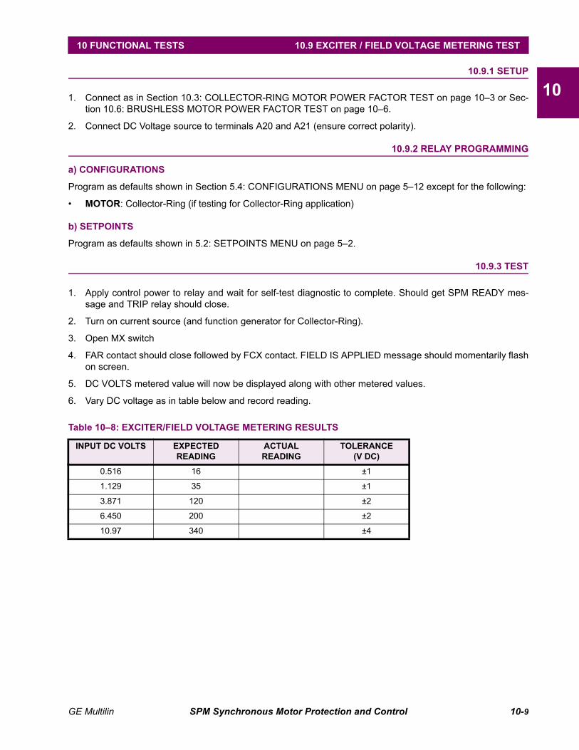
GE Multilin SPM Synchronous Motor Protection and Control 10-9
10 FUNCTIONAL TESTS 10.9 EXCITER / FIELD VOLTAGE METERING TEST
1010.9 EXCITER / FIELD VOLTAGE METERING TEST 10.9.1 SETUP
1. Connect as in Section 10.3: COLLECTOR-RING MOTOR POWER FACTOR TEST on page 10–3 or Sec-tion 10.6: BRUSHLESS MOTOR POWER FACTOR TEST on page 10–6.
2. Connect DC Voltage source to terminals A20 and A21 (ensure correct polarity).
10.9.2 RELAY PROGRAMMING
a) CONFIGURATIONS
Program as defaults shown in Section 5.4: CONFIGURATIONS MENU on page 5–12 except for the following:
• MOTOR: Collector-Ring (if testing for Collector-Ring application)
b) SETPOINTS
Program as defaults shown in 5.2: SETPOINTS MENU on page 5–2.
10.9.3 TEST
1. Apply control power to relay and wait for self-test diagnostic to complete. Should get SPM READY mes-sage and TRIP relay should close.
2. Turn on current source (and function generator for Collector-Ring).
3. Open MX switch
4. FAR contact should close followed by FCX contact. FIELD IS APPLIED message should momentarily flashon screen.
5. DC VOLTS metered value will now be displayed along with other metered values.
6. Vary DC voltage as in table below and record reading.
Table 10–8: EXCITER/FIELD VOLTAGE METERING RESULTS
INPUT DC VOLTS EXPECTED READING
ACTUAL READING
TOLERANCE(V DC)
0.516 16 ±1
1.129 35 ±1
3.871 120 ±2
6.450 200 ±2
10.97 340 ±4

10-10 SPM Synchronous Motor Protection and Control GE Multilin
10.10 EXCITER / FIELD CURRENT METERING TEST 10 FUNCTIONAL TESTS
1010.10 EXCITER / FIELD CURRENT METERING TEST 10.10.1 SETUP
1. Connect as in Section 10.3: COLLECTOR-RING MOTOR POWER FACTOR TEST on page 10–3 or Sec-tion 10.6: BRUSHLESS MOTOR POWER FACTOR TEST on page 10–6.
2. Connect DC Voltage source to terminals A24 and A25 (ensure correct polarity).
3. Note this test is done as secondary injection testing without the CM or DCCT.
10.10.2 RELAY PROGRAMMING
a) CONFIGURATIONS
Program as defaults shown in Section 5.4: CONFIGURATIONS MENU on page 5–12 except for the following:
• MOTOR: Collector-Ring (if testing for Collector-Ring application)
b) SETPOINTS
Program as defaults shown in 5.2: SETPOINTS MENU on page 5–2.
10.10.3 TEST
1. Apply control power to relay and wait for self-test diagnostic to complete. Should get SPM READY mes-sage and TRIP relay should close.
2. Turn on current source (and function generator for Collector-Ring).
3. Open MX switch
4. FAR contact should close followed by FCX contact. FIELD IS APPLIED message should momentarily flashon screen.
5. DC AMPS metered value will now be displayed along with other metered values.
6. Vary DC voltage as in table below and record reading.
Table 10–9: EXCITER/FIELD CURRENT METERING RESULTS
INPUT DC VOLTS EXPECTED READING
ACTUAL READING
TOLERANCE(A DC)
0.157 0.5 A ±.0.1 A
0.471 1.5 A ±.0.1 A
0.942 3 A ±.0.1 A
1.256 4 A ±.0.1 A
1.570 5 A ±.0.1 A

GE Multilin SPM Synchronous Motor Protection and Control A-1
APPENDIX A A.1 COMMISSIONING
AAPPENDIX A COMMISSIONINGA.1 COMMISSIONING A.1.1 COLLECTOR-RING SETTINGS
DESCRIPTION DEFAULT USER VALUE
SETPOINTS
PF TRIP –0.60
PF DELAY 1.0 s
PF SUPP 6% FLC
PF MODE ridethru
FAR DELAY 0 s
FCX DELAY 1 s
AC CT RTG 50/5
FL AMPS 25
LR AMPS 200
SYNC SLIP 5.0%
STALL TIME 10 s
RUNTIME 1.05 x ST
DC CT PRIM 5 A
HIGH FIELD OFF
FIELD AMPS OFF
FLD IE DLY N/A
FIELD VOLTS OFF
EX VLT DELAY N/A
INC SEQ DLY OFF
REG PF 0.00
REG GAIN 1
STABILITY 1 cyc
REG OUTPUT 1 V
FLOOR VOLTS 0.0
CONFIGURATIONS
MOTOR Coll-Ring
LINE FREQ 60 Hz
PF REF internal
RTU ADDRESS 1
BAUD RATE 19.2k
PARITY None
TURNAROUND 5
STAT read only
PASSWORD 0000
CALIBRATION
FS EXC VOLT
FS EXC AMPS
FS MTR AMPS
DESCRIPTION DEFAULT USER VALUE
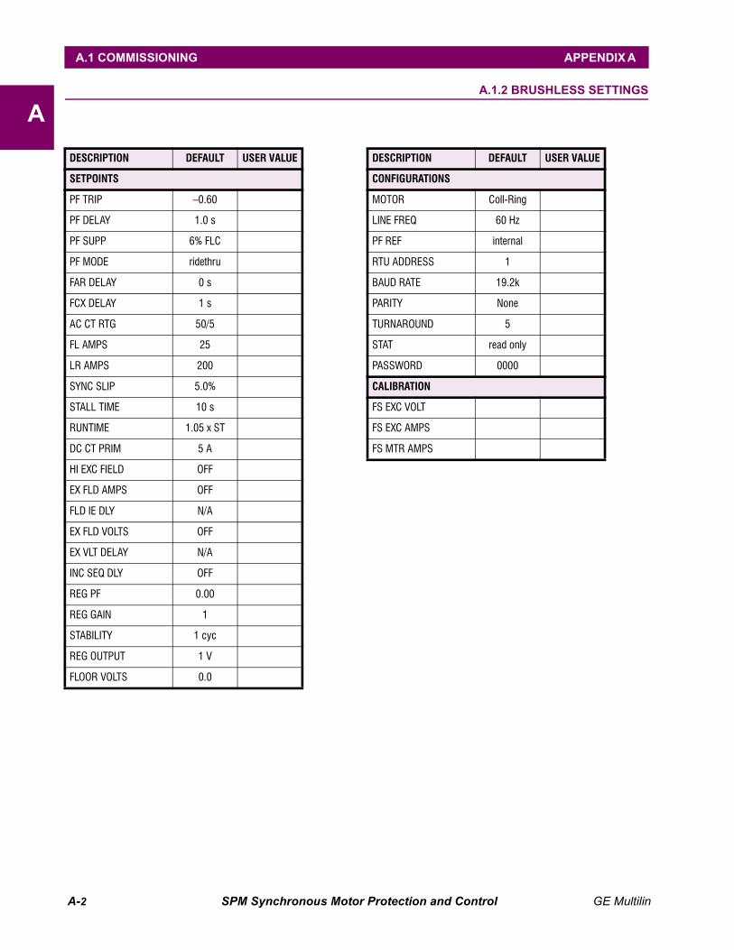
A-2 SPM Synchronous Motor Protection and Control GE Multilin
A.1 COMMISSIONING APPENDIX A
AA.1.2 BRUSHLESS SETTINGS
DESCRIPTION DEFAULT USER VALUE
SETPOINTS
PF TRIP –0.60
PF DELAY 1.0 s
PF SUPP 6% FLC
PF MODE ridethru
FAR DELAY 0 s
FCX DELAY 1 s
AC CT RTG 50/5
FL AMPS 25
LR AMPS 200
SYNC SLIP 5.0%
STALL TIME 10 s
RUNTIME 1.05 x ST
DC CT PRIM 5 A
HI EXC FIELD OFF
EX FLD AMPS OFF
FLD IE DLY N/A
EX FLD VOLTS OFF
EX VLT DELAY N/A
INC SEQ DLY OFF
REG PF 0.00
REG GAIN 1
STABILITY 1 cyc
REG OUTPUT 1 V
FLOOR VOLTS 0.0
CONFIGURATIONS
MOTOR Coll-Ring
LINE FREQ 60 Hz
PF REF internal
RTU ADDRESS 1
BAUD RATE 19.2k
PARITY None
TURNAROUND 5
STAT read only
PASSWORD 0000
CALIBRATION
FS EXC VOLT
FS EXC AMPS
FS MTR AMPS
DESCRIPTION DEFAULT USER VALUE

GE Multilin SPM Synchronous Motor Protection and Control B-1
APPENDIX B B.1 WARRANTY
B
APPENDIX B WARRANTYB.1 WARRANTY B.1.1 WARRANTY
GE MULTILIN RELAY WARRANTYGeneral Electric Multilin Inc. (GE Multilin) warrants each relay it manu-factures to be free from defects in material and workmanship undernormal use and service for a period of 24 months from date of ship-ment from factory.
In the event of a failure covered by warranty, GE Multilin will undertaketo repair or replace the relay providing the warrantor determined that itis defective and it is returned with all transportation charges prepaid toan authorized service centre or the factory. Repairs or replacementunder warranty will be made without charge.
Warranty shall not apply to any relay which has been subject to mis-use, negligence, accident, incorrect installation or use not in accor-dance with instructions nor any unit that has been altered outside a GEMultilin authorized factory outlet.
GE Multilin is not liable for special, indirect or consequential damagesor for loss of profit or for expenses sustained as a result of a relay mal-function, incorrect application or adjustment.
For complete text of Warranty (including limitations and disclaimers),refer to GE Multilin Standard Conditions of Sale.

B-2 SPM Synchronous Motor Protection and Control GE Multilin
B.1 WARRANTY APPENDIX B
B
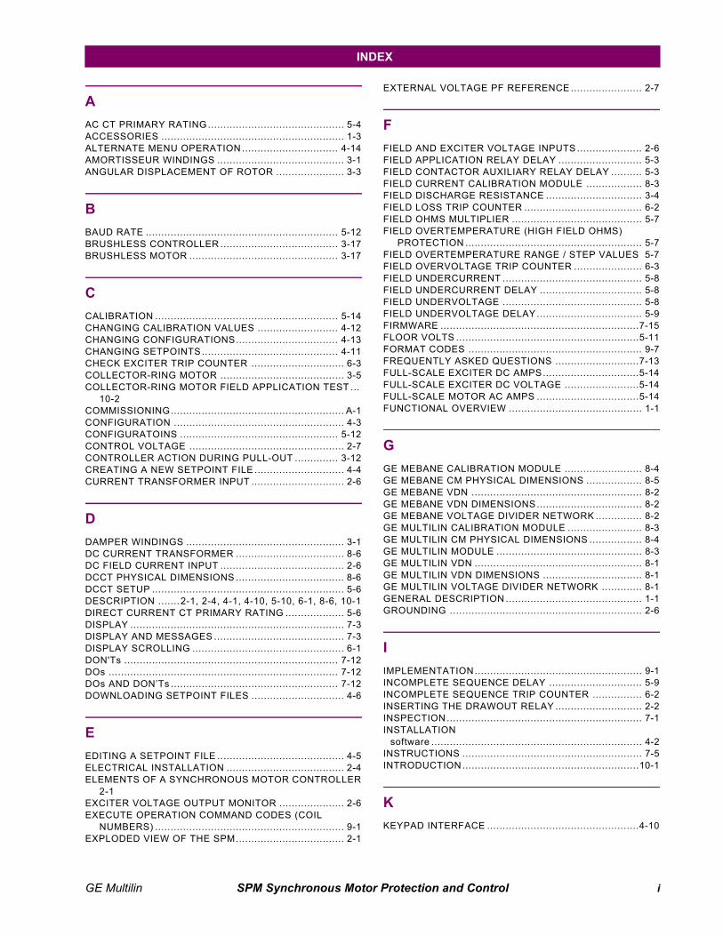
GE Multilin SPM Synchronous Motor Protection and Control i
INDEX
AAC CT PRIMARY RATING ............................................ 5-4ACCESSORIES ........................................................... 1-3ALTERNATE MENU OPERATION ............................... 4-14AMORTISSEUR WINDINGS ......................................... 3-1ANGULAR DISPLACEMENT OF ROTOR ...................... 3-3
BBAUD RATE .............................................................. 5-12BRUSHLESS CONTROLLER ...................................... 3-17BRUSHLESS MOTOR ................................................ 3-17
CCALIBRATION ........................................................... 5-14CHANGING CALIBRATION VALUES .......................... 4-12CHANGING CONFIGURATIONS................................. 4-13CHANGING SETPOINTS............................................ 4-11CHECK EXCITER TRIP COUNTER .............................. 6-3COLLECTOR-RING MOTOR ........................................ 3-5COLLECTOR-RING MOTOR FIELD APPLICATION TEST ...
10-2COMMISSIONING........................................................ A-1CONFIGURATION ....................................................... 4-3CONFIGURATOINS ................................................... 5-12CONTROL VOLTAGE .................................................. 2-7CONTROLLER ACTION DURING PULL-OUT .............. 3-12CREATING A NEW SETPOINT FILE ............................. 4-4CURRENT TRANSFORMER INPUT .............................. 2-6
DDAMPER WINDINGS ................................................... 3-1DC CURRENT TRANSFORMER ................................... 8-6DC FIELD CURRENT INPUT ........................................ 2-6DCCT PHYSICAL DIMENSIONS ................................... 8-6DCCT SETUP .............................................................. 5-6DESCRIPTION ....... 2-1, 2-4, 4-1, 4-10, 5-10, 6-1, 8-6, 10-1DIRECT CURRENT CT PRIMARY RATING ................... 5-6DISPLAY ..................................................................... 7-3DISPLAY AND MESSAGES .......................................... 7-3DISPLAY SCROLLING ................................................. 6-1DON'Ts ..................................................................... 7-12DOs .......................................................................... 7-12DOs AND DON’Ts ...................................................... 7-12DOWNLOADING SETPOINT FILES .............................. 4-6
EEDITING A SETPOINT FILE ......................................... 4-5ELECTRICAL INSTALLATION ...................................... 2-4ELEMENTS OF A SYNCHRONOUS MOTOR CONTROLLER
2-1EXCITER VOLTAGE OUTPUT MONITOR ..................... 2-6EXECUTE OPERATION COMMAND CODES (COIL
NUMBERS) ............................................................. 9-1EXPLODED VIEW OF THE SPM................................... 2-1
EXTERNAL VOLTAGE PF REFERENCE ....................... 2-7
FFIELD AND EXCITER VOLTAGE INPUTS ..................... 2-6FIELD APPLICATION RELAY DELAY ........................... 5-3FIELD CONTACTOR AUXILIARY RELAY DELAY .......... 5-3FIELD CURRENT CALIBRATION MODULE .................. 8-3FIELD DISCHARGE RESISTANCE ............................... 3-4FIELD LOSS TRIP COUNTER ...................................... 6-2FIELD OHMS MULTIPLIER .......................................... 5-7FIELD OVERTEMPERATURE (HIGH FIELD OHMS)
PROTECTION ......................................................... 5-7FIELD OVERTEMPERATURE RANGE / STEP VALUES 5-7FIELD OVERVOLTAGE TRIP COUNTER ...................... 6-3FIELD UNDERCURRENT ............................................. 5-8FIELD UNDERCURRENT DELAY ................................. 5-8FIELD UNDERVOLTAGE ............................................. 5-8FIELD UNDERVOLTAGE DELAY.................................. 5-9FIRMWARE ................................................................7-15FLOOR VOLTS ...........................................................5-11FORMAT CODES ........................................................ 9-7FREQUENTLY ASKED QUESTIONS ...........................7-13FULL-SCALE EXCITER DC AMPS...............................5-14FULL-SCALE EXCITER DC VOLTAGE ........................5-14FULL-SCALE MOTOR AC AMPS .................................5-14FUNCTIONAL OVERVIEW ........................................... 1-1
GGE MEBANE CALIBRATION MODULE ......................... 8-4GE MEBANE CM PHYSICAL DIMENSIONS .................. 8-5GE MEBANE VDN ....................................................... 8-2GE MEBANE VDN DIMENSIONS.................................. 8-2GE MEBANE VOLTAGE DIVIDER NETWORK ............... 8-2GE MULTILIN CALIBRATION MODULE ........................ 8-3GE MULTILIN CM PHYSICAL DIMENSIONS ................. 8-4GE MULTILIN MODULE ............................................... 8-3GE MULTILIN VDN ...................................................... 8-1GE MULTILIN VDN DIMENSIONS ................................ 8-1GE MULTILIN VOLTAGE DIVIDER NETWORK ............. 8-1GENERAL DESCRIPTION ............................................ 1-1GROUNDING .............................................................. 2-6
IIMPLEMENTATION...................................................... 9-1INCOMPLETE SEQUENCE DELAY .............................. 5-9INCOMPLETE SEQUENCE TRIP COUNTER ................ 6-2INSERTING THE DRAWOUT RELAY ............................ 2-2INSPECTION ............................................................... 7-1INSTALLATION
software .................................................................... 4-2INSTRUCTIONS .......................................................... 7-5INTRODUCTION.........................................................10-1
KKEYPAD INTERFACE .................................................4-10
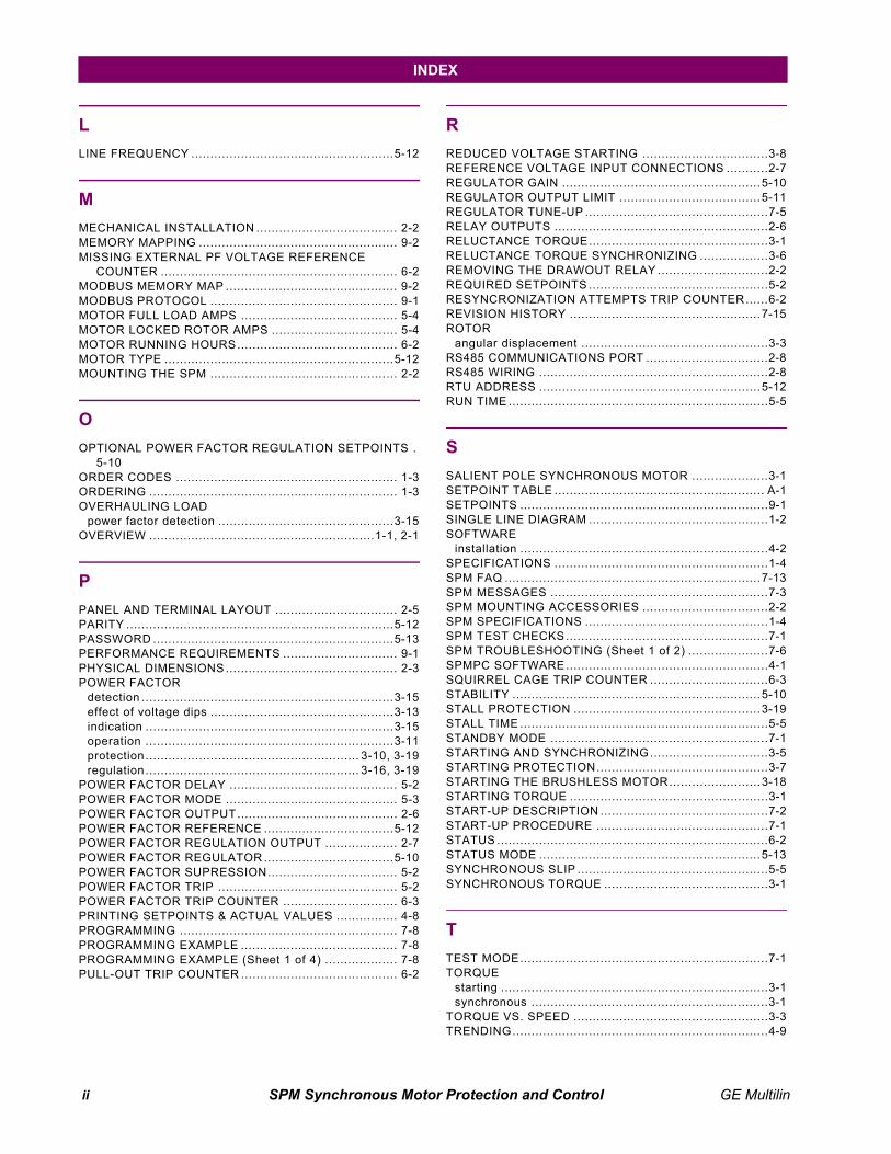
ii SPM Synchronous Motor Protection and Control GE Multilin
INDEX
LLINE FREQUENCY .....................................................5-12
MMECHANICAL INSTALLATION ..................................... 2-2MEMORY MAPPING .................................................... 9-2MISSING EXTERNAL PF VOLTAGE REFERENCE
COUNTER .............................................................. 6-2MODBUS MEMORY MAP ............................................. 9-2MODBUS PROTOCOL ................................................. 9-1MOTOR FULL LOAD AMPS ......................................... 5-4MOTOR LOCKED ROTOR AMPS ................................. 5-4MOTOR RUNNING HOURS.......................................... 6-2MOTOR TYPE ............................................................5-12MOUNTING THE SPM ................................................. 2-2
OOPTIONAL POWER FACTOR REGULATION SETPOINTS .
5-10ORDER CODES .......................................................... 1-3ORDERING ................................................................. 1-3OVERHAULING LOAD
power factor detection ..............................................3-15OVERVIEW ...........................................................1-1, 2-1
PPANEL AND TERMINAL LAYOUT ................................ 2-5PARITY ......................................................................5-12PASSWORD ...............................................................5-13PERFORMANCE REQUIREMENTS .............................. 9-1PHYSICAL DIMENSIONS ............................................. 2-3POWER FACTOR
detection ..................................................................3-15effect of voltage dips ................................................3-13indication .................................................................3-15operation .................................................................3-11protection ........................................................ 3-10, 3-19regulation ........................................................ 3-16, 3-19
POWER FACTOR DELAY ............................................ 5-2POWER FACTOR MODE ............................................. 5-3POWER FACTOR OUTPUT.......................................... 2-6POWER FACTOR REFERENCE ..................................5-12POWER FACTOR REGULATION OUTPUT ................... 2-7POWER FACTOR REGULATOR ..................................5-10POWER FACTOR SUPRESSION.................................. 5-2POWER FACTOR TRIP ............................................... 5-2POWER FACTOR TRIP COUNTER .............................. 6-3PRINTING SETPOINTS & ACTUAL VALUES ................ 4-8PROGRAMMING ......................................................... 7-8PROGRAMMING EXAMPLE ......................................... 7-8PROGRAMMING EXAMPLE (Sheet 1 of 4) ................... 7-8PULL-OUT TRIP COUNTER ......................................... 6-2
RREDUCED VOLTAGE STARTING .................................3-8REFERENCE VOLTAGE INPUT CONNECTIONS ...........2-7REGULATOR GAIN ....................................................5-10REGULATOR OUTPUT LIMIT .....................................5-11REGULATOR TUNE-UP ................................................7-5RELAY OUTPUTS ........................................................2-6RELUCTANCE TORQUE...............................................3-1RELUCTANCE TORQUE SYNCHRONIZING ..................3-6REMOVING THE DRAWOUT RELAY .............................2-2REQUIRED SETPOINTS ...............................................5-2RESYNCRONIZATION ATTEMPTS TRIP COUNTER......6-2REVISION HISTORY ..................................................7-15ROTOR
angular displacement .................................................3-3RS485 COMMUNICATIONS PORT ................................2-8RS485 WIRING ............................................................2-8RTU ADDRESS ..........................................................5-12RUN TIME ....................................................................5-5
SSALIENT POLE SYNCHRONOUS MOTOR ....................3-1SETPOINT TABLE ....................................................... A-1SETPOINTS .................................................................9-1SINGLE LINE DIAGRAM ...............................................1-2SOFTWARE
installation .................................................................4-2SPECIFICATIONS ........................................................1-4SPM FAQ ...................................................................7-13SPM MESSAGES .........................................................7-3SPM MOUNTING ACCESSORIES .................................2-2SPM SPECIFICATIONS ................................................1-4SPM TEST CHECKS.....................................................7-1SPM TROUBLESHOOTING (Sheet 1 of 2) .....................7-6SPMPC SOFTWARE.....................................................4-1SQUIRREL CAGE TRIP COUNTER ...............................6-3STABILITY .................................................................5-10STALL PROTECTION .................................................3-19STALL TIME .................................................................5-5STANDBY MODE .........................................................7-1STARTING AND SYNCHRONIZING...............................3-5STARTING PROTECTION.............................................3-7STARTING THE BRUSHLESS MOTOR........................3-18STARTING TORQUE ....................................................3-1START-UP DESCRIPTION ............................................7-2START-UP PROCEDURE .............................................7-1STATUS .......................................................................6-2STATUS MODE ..........................................................5-13SYNCHRONOUS SLIP ..................................................5-5SYNCHRONOUS TORQUE ...........................................3-1
TTEST MODE.................................................................7-1TORQUE
starting ......................................................................3-1synchronous ..............................................................3-1
TORQUE VS. SPEED ...................................................3-3TRENDING...................................................................4-9

GE Multilin SPM Synchronous Motor Protection and Control iii
INDEX
TROUBLESHOOTING .................................................. 7-6TROUBLESHOOTING GUIDE....................................... 7-6TURNAROUND .......................................................... 5-13TYPICAL ROTOR FLUX AND CURRENT AT PULL-IN ... 3-2TYPICAL TRANSFORMER ACTION OF ROTOR FLUX AND
CURENT (CONSTANT SLIP) ................................... 3-2TYPICAL WIRING DIAGRAM........................................ 2-4
UUNPACKING THE SPM ................................................ 2-2
VVIEWING & CHANGING STATUS MODE PARAMETERS 4-
14VOLTAGE DIVIDER NETWORK ................................... 8-1
WWARRANTY ................................................................ B-1WEBSITE .................................................................... 4-2

iv SPM Synchronous Motor Protection and Control GE Multilin
INDEX

GE Multilin SPM Synchronous Motor Protection and Control
NOTES
SPM Synchronous Motor Protection and Control GE Multilin
GE POWER MANAGEMENT WEBSITE
The latest product information for the SPM Synchronous Motor Protection and Control relay is available on theInternet via the GE Multilin home page:
http://www.GEmultilin.com
This site provides access to the following customer services:
• Digital Products DirectoryA brief description of products can be viewed online.
• Product CatalogIndividual product brochures can be downloaded and printed
• Product Selector GuideA graphical tool for finding the product you are inter-ested in
• Sales OfficesA complete listing of world-wide sales offices
• Technical SupportComplete contact information is available
• Instruction ManualsManuals for many products are now available online
• GE Product SoftwareThe latest working versions of product software
• Technical DrawingsMany technical drawings are available in either AutoCAD, CorelDRAW, or PDF formats.
• Order CodesOrder codes for many products can be downloaded and printed
• Technical PublicationsPapers related to power management
Much more is also available. Visit us online at: www.GEmultilin.com