ge fanuc automation - logic control · systems. ge fanuc automation assumes no obligation of notice...
TRANSCRIPT

ÎÎ
GE Fanuc Automation
Programmable Control Products
Series 90� PLCAxis Positioning Module (APM)
Programmer’s Manual
GFK–0664A August 1993

GFL–002
Warnings, Cautions, and Notesas Used in this Publication
Warning
Warning notices are used in this publication to emphasize that hazardous voltages,currents, temperatures, or other conditions that could cause personal injury exist in thisequipment or may be associated with its use.
In situations where inattention could cause either personal injury or damage toequipment, a Warning notice is used.
Caution
Caution notices are used where equipment might be damaged if care is not taken.
Note
Notes merely call attention to information that is especially significant to understandingand operating the equipment.
This document is based on information available at the time of its publication. Whileefforts have been made to be accurate, the information contained herein does notpurport to cover all details or variations in hardware or software, nor to provide forevery possible contingency in connection with installation, operation, or maintenance.Features may be described herein which are not present in all hardware and softwaresystems. GE Fanuc Automation assumes no obligation of notice to holders of thisdocument with respect to changes subsequently made.
GE Fanuc Automation makes no representation or warranty, expressed, implied, orstatutory with respect to, and assumes no responsibility for the accuracy, completeness,sufficiency, or usefulness of the information contained herein. No warranties ofmerchantability or fitness for purpose shall apply.
The following are trademarks of GE Fanuc Automation North America, Inc.
Alarm Master CIMSTAR Helpmate PROMACRO Series SixCIMPLICITY GEnet Logicmaster Series One Series 90CIMPLICITY 90–ADS Genius Modelmaster Series Three VuMasterCIMPLICITY PowerTRAC Genius PowerTRAC ProLoop Series Five Workmaster
Copyright 1993 GE Fanuc Automation North America, Inc.All Rights Reserved
iii GFK-0664
Preface
Content of This Manual
This manual describes how to program the Series 90 Programmable Controller Axis PositioningModules. Included in Chapter 2 is a complete description of the Motion Programmer Softwarewhich is used to create Motion Programs. In addition, Chapter 3 provides several practical ex-amples including combinations of Motion Commands. The Appendices provide detailed de-scriptions of the Motion Commands as well as the Status and Control data that are transferredautomatically each sweep from the PLC to the APM.
Chapter 1. Introduction to Motion Programming: This chapter is an overview of boththe Motion Programmer Software and the Program Zero Editor (which is partof the Logicmaster 90 Configuration software). Operation of the ProgramZero Editor is provided in GFK–0840, The APM30 Standard Mode User’sManual, but the appendices and some of the program examples in this manualapply to it as well.
Chapter 2. The Motion Programmer: This chapter is a comprehensive description ofthe Motion Programmer Software.
Chapter 3. Motion Program Examples: This chapter includes several examples de-scribing how to combine Motion Commands to produce desired effects.
Appendix A. The APM Motion Commands: This appendix includes all the Motion Com-mands with detailed descriptions.
Appendix B. The APM Discrete Commands (%Q): This appendix includes all the Dis-crete Commands with detailed descriptions.
Appendix C. The APM Immediate Commands (%AQ): This appendix includes all theImmediate Commands with detailed descriptions.
Appendix D. The APM Status Bits (%I): This appendix includes all the Status Bits withdetailed descriptions.
Appendix E. The APM Status Words (%AI): This appendix includes all the StatusWords with detailed descriptions. APM Error Codes are listed here.
Preface
iv Series 90 Axis Positioning Module (APM) Programmer’s Manual - August 1993 GFK-0664
Related Publications
GFK–0840 Series 90�–30 Programmable Controllers Axis Positioning Module (APM30) – Standard Mode User’s Manual
GFK–0781 Series 90�–30 Programmable Controllers Axis Positioning Module (APM30) – Follower Mode User’s Manual
GFK–0466 Logicmaster�90 Series 90�–30 and 90�–20 Programming Software User’s Manual
GFK–0265 Logicmaster�90 Programming Software Reference Manual
GFK–0356 Series 90�–30 Programmable Controller Installation and Operation Manual
At GE Fanuc Automation, we strive to produce quality technical documentation. After youhave used this manual, please take a few mooments to complete and return the Reader’s Com-ment Card located on the next page.

Contents
v
GFK–0664A Series 90 PLC Axis Positioning Module (APM) Programmer’s Manual - August 1993
Chapter 1 Introduction to APM Programming 1-1 . . . . . . . . . . . . . . . . . . . . . . . . . .
Introduction to APM Programming 1-1 . . . . . . . . . . . . . . . . . . . . . . . . . . . . . . . . .
The Motion Programmer 1-2 . . . . . . . . . . . . . . . . . . . . . . . . . . . . . . . . . . . . . . . .
Instruction Format 1-3 . . . . . . . . . . . . . . . . . . . . . . . . . . . . . . . . . . . . . .
The Program Zero Editor 1-4 . . . . . . . . . . . . . . . . . . . . . . . . . . . . . . . . . . . . . . .
Chapter 2 Motion Programmer 2-1 . . . . . . . . . . . . . . . . . . . . . . . . . . . . . . . . . . . . . . . .
Section 1: Starting-Up the Motion Programmer 2-2 . . . . . . . . . . . . . . .
Installing the Motion Programmer Software 2-2 . . . . . . . . . . . . . . . . . . . . . . . . . .
Starting-Up the Motion Programmer 2-4 . . . . . . . . . . . . . . . . . . . . . . . . . . . . . . . .
Creating and Selecting a Folder 2-4 . . . . . . . . . . . . . . . . . . . . . . . . . . . . . . . . . .
Creating an APM File 2-7 . . . . . . . . . . . . . . . . . . . . . . . . . . . . . . . . . . . . . . . . . . .
The Motion Programmer Main Screen 2-8 . . . . . . . . . . . . . . . . . . . . . . . . . . . .
Motion Programmer Functions 2-8 . . . . . . . . . . . . . . . . . . . . . . . . . . . . . . . . . . .
Message Line 2-9 . . . . . . . . . . . . . . . . . . . . . . . . . . . . . . . . . . . . . . . . . . . . . . . . . .
Command Line 2-9 . . . . . . . . . . . . . . . . . . . . . . . . . . . . . . . . . . . . . . . . . . . . . . . .
Status Line Definition 2-9 . . . . . . . . . . . . . . . . . . . . . . . . . . . . . . . . . . . . . . . . . . .
Help and Special Function Keys 2-10 . . . . . . . . . . . . . . . . . . . . . . . . . . . . . . . . . .
Establishing Communications Between the APM and Programmer 2-11 . . . .
Section 2. Creating and Editing Programs and Subroutines 2-12 . . . .
Displaying a Program 2-12 . . . . . . . . . . . . . . . . . . . . . . . . . . . . . . . . . . . . . . . . . . . . .
Functions Accessed from Display Mode 2-13 . . . . . . . . . . . . . . . . . . . . . . . . . . .
Additional Status Fields 2-13 . . . . . . . . . . . . . . . . . . . . . . . . . . . . . . . . . . . . . . . . .
Program Edit Fields 2-14 . . . . . . . . . . . . . . . . . . . . . . . . . . . . . . . . . . . . . . . . . . . . .
Moving the Cursor 2-15 . . . . . . . . . . . . . . . . . . . . . . . . . . . . . . . . . . . . . . . . . . . . .
APM Motion Command List 2-15 . . . . . . . . . . . . . . . . . . . . . . . . . . . . . . . . . . . . . . .
Inserting Lines in a Program or Subroutine 2-16 . . . . . . . . . . . . . . . . . . . . . . . . . . .
Making Changes to a Program or Subroutine 2-17 . . . . . . . . . . . . . . . . . . . . . . . . .
Deleting a Line 2-18 . . . . . . . . . . . . . . . . . . . . . . . . . . . . . . . . . . . . . . . . . . . . . . . . . . .
Checking Program or Subroutine Syntax 2-18 . . . . . . . . . . . . . . . . . . . . . . . . . . . . .
Renumbering Block Numbers 2-19 . . . . . . . . . . . . . . . . . . . . . . . . . . . . . . . . . . . . . .
Using the GoTo Function 2-19 . . . . . . . . . . . . . . . . . . . . . . . . . . . . . . . . . . . . . . . . . . .
Size Limitations 2-20 . . . . . . . . . . . . . . . . . . . . . . . . . . . . . . . . . . . . . . . . . . . . . . . . . .
Contents
vi
GFK–0664A Series 90 PLC Axis Positioning Module (APM) Programmer’s Manual - August 1993
Section 3. Status Functions 2-21 . . . . . . . . . . . . . . . . . . . . . . . . . . . . . . . . .
Section 4. Using APM Files and Folders 2-22 . . . . . . . . . . . . . . . . . . . . .
APM File Functions (F5) 2-23 . . . . . . . . . . . . . . . . . . . . . . . . . . . . . . . . . . . . . . . . . . . Selecting and Creating APM Files 2-23 . . . . . . . . . . . . . . . . . . . . . . . . . . . . . . . . Deleting an APM File 2-25 . . . . . . . . . . . . . . . . . . . . . . . . . . . . . . . . . . . . . . . . . . . Selecting and Configuring APM Programs and Subroutines 2-26 . . . . . . . . . . Copying APM Files 2-28 . . . . . . . . . . . . . . . . . . . . . . . . . . . . . . . . . . . . . . . . . . . . .
Folder Functions (F8) 2-29 . . . . . . . . . . . . . . . . . . . . . . . . . . . . . . . . . . . . . . . . . . . . . . Selecting and Creating a Folder 2-30 . . . . . . . . . . . . . . . . . . . . . . . . . . . . . . . . . . Deleting a Folder 2-31 . . . . . . . . . . . . . . . . . . . . . . . . . . . . . . . . . . . . . . . . . . . . . . Backing-Up All APM Files in a Folder 2-32 . . . . . . . . . . . . . . . . . . . . . . . . . . . . . Restoring All APM Files in a Folder 2-33 . . . . . . . . . . . . . . . . . . . . . . . . . . . . . . . Clearing All APM Files in a Folder 2-34 . . . . . . . . . . . . . . . . . . . . . . . . . . . . . . . . Locking and Unlocking Current Program Folder 2-35 . . . . . . . . . . . . . . . . . . . Copying All APM Files in a Folder 2-36 . . . . . . . . . . . . . . . . . . . . . . . . . . . . . . . .
Section 5. Setting-Up the Programmer Ports 2-37 . . . . . . . . . . . . . . . . . .
Setting-Up the Printer Serial Port 2-37 . . . . . . . . . . . . . . . . . . . . . . . . . . . . . . . . . . .
Setting the Programmer Mode 2-39 . . . . . . . . . . . . . . . . . . . . . . . . . . . . . . . . . . . . . .
Setting-Up APM Communications 2-40 . . . . . . . . . . . . . . . . . . . . . . . . . . . . . . . . . . The Select SNP Connections Screen 2-40 . . . . . . . . . . . . . . . . . . . . . . . . . . . . . . The PLC Communications Port Setup Screen 2-41 . . . . . . . . . . . . . . . . . . . . . .
Section 6. Loading and Storing APM Files 2-43 . . . . . . . . . . . . . . . . . . .
Loading from the APM to the Programmer 2-43 . . . . . . . . . . . . . . . . . . . . . . . . . . .
Storing from the Programmer to the APM 2-45 . . . . . . . . . . . . . . . . . . . . . . . . . . . .
Verifying the APM with the Programmer 2-47 . . . . . . . . . . . . . . . . . . . . . . . . . . . . .
Clearing APM Memory 2-48 . . . . . . . . . . . . . . . . . . . . . . . . . . . . . . . . . . . . . . . . . . . .
EEPROM Operations 2-50 . . . . . . . . . . . . . . . . . . . . . . . . . . . . . . . . . . . . . . . . . . . . .
Section 7. Printing APM Files 2-52 . . . . . . . . . . . . . . . . . . . . . . . . . . . . . .
Setting-Up Printer Parameters 2-52 . . . . . . . . . . . . . . . . . . . . . . . . . . . . . . . . . . . . . .
Selecting the Screen Print Destination 2-54 . . . . . . . . . . . . . . . . . . . . . . . . . . . . . . .
Printing Programs and Subroutines 2-55 . . . . . . . . . . . . . . . . . . . . . . . . . . . . . . . . . Pausing the Print Operation 2-56 . . . . . . . . . . . . . . . . . . . . . . . . . . . . . . . . . . . . .
Chapter 3 Motion Program Examples 3-1 . . . . . . . . . . . . . . . . . . . . . . . . . . . . . . . . . .
Calculating Move Distances 3-1 . . . . . . . . . . . . . . . . . . . . . . . . . . . . . . . . . . . . . . . .
Single Pmove 3-3 . . . . . . . . . . . . . . . . . . . . . . . . . . . . . . . . . . . . . . . . . . . . . . . . . . . .
Cmove Followed by Pmove 3-5 . . . . . . . . . . . . . . . . . . . . . . . . . . . . . . . . . . . . . . . .
Multiple Cmoves 3-7 . . . . . . . . . . . . . . . . . . . . . . . . . . . . . . . . . . . . . . . . . . . . . . . . .
Using the Jump Command 3-8 . . . . . . . . . . . . . . . . . . . . . . . . . . . . . . . . . . . . . . . . .
Contents
vii
GFK–0664A Series 90 PLC Axis Positioning Module (APM) Programmer’s Manual - August 1993
Appendix A APM Motion Commands A-1 . . . . . . . . . . . . . . . . . . . . . . . . . . . . . . . . . . .
Acceleration A-2 . . . . . . . . . . . . . . . . . . . . . . . . . . . . . . . . . . . . . . . . . . . . . . . . . . . . .
Block A-2 . . . . . . . . . . . . . . . . . . . . . . . . . . . . . . . . . . . . . . . . . . . . . . . . . . . . . . . . . . .
Call Subroutine A-3 . . . . . . . . . . . . . . . . . . . . . . . . . . . . . . . . . . . . . . . . . . . . . . . . . . .
Cmove A-3 . . . . . . . . . . . . . . . . . . . . . . . . . . . . . . . . . . . . . . . . . . . . . . . . . . . . . . . . . .
Dwell A-4 . . . . . . . . . . . . . . . . . . . . . . . . . . . . . . . . . . . . . . . . . . . . . . . . . . . . . . . . . . .
Jump A-4 . . . . . . . . . . . . . . . . . . . . . . . . . . . . . . . . . . . . . . . . . . . . . . . . . . . . . . . . . . .
Load Parameter A-5 . . . . . . . . . . . . . . . . . . . . . . . . . . . . . . . . . . . . . . . . . . . . . . . . . .
Null A-5 . . . . . . . . . . . . . . . . . . . . . . . . . . . . . . . . . . . . . . . . . . . . . . . . . . . . . . . . . . . .
Pmove A-6 . . . . . . . . . . . . . . . . . . . . . . . . . . . . . . . . . . . . . . . . . . . . . . . . . . . . . . . . . .
Velocity A-7 . . . . . . . . . . . . . . . . . . . . . . . . . . . . . . . . . . . . . . . . . . . . . . . . . . . . . . . . .
Wait A-7 . . . . . . . . . . . . . . . . . . . . . . . . . . . . . . . . . . . . . . . . . . . . . . . . . . . . . . . . . . . .
Appendix B APM Discrete Commands (%Q) B-1 . . . . . . . . . . . . . . . . . . . . . . . . . . . . .
Abort All Moves B-2 . . . . . . . . . . . . . . . . . . . . . . . . . . . . . . . . . . . . . . . . . . . . . . . . . .
Clear Error B-2 . . . . . . . . . . . . . . . . . . . . . . . . . . . . . . . . . . . . . . . . . . . . . . . . . . . . . . .
CTL09-CTL12 Output Controls B-3 . . . . . . . . . . . . . . . . . . . . . . . . . . . . . . . . . . . . .
Enable Drive B-3 . . . . . . . . . . . . . . . . . . . . . . . . . . . . . . . . . . . . . . . . . . . . . . . . . . . . .
Execute Motion Program 0-10 B-4 . . . . . . . . . . . . . . . . . . . . . . . . . . . . . . . . . . . . . .
Feedhold (On Transition) B-4 . . . . . . . . . . . . . . . . . . . . . . . . . . . . . . . . . . . . . . . . . .
Feedhold (Off Transition) B-5 . . . . . . . . . . . . . . . . . . . . . . . . . . . . . . . . . . . . . . . . . .
Find Home B-5 . . . . . . . . . . . . . . . . . . . . . . . . . . . . . . . . . . . . . . . . . . . . . . . . . . . . . .
Jog Minus B-7 . . . . . . . . . . . . . . . . . . . . . . . . . . . . . . . . . . . . . . . . . . . . . . . . . . . . . . .
Jog Plus B-8 . . . . . . . . . . . . . . . . . . . . . . . . . . . . . . . . . . . . . . . . . . . . . . . . . . . . . . . . .
Reset Strobe Flag B-9 . . . . . . . . . . . . . . . . . . . . . . . . . . . . . . . . . . . . . . . . . . . . . . . . .
Appendix C APM Immediate Commands (%AQ) C-1 . . . . . . . . . . . . . . . . . . . . . . . . . .
Force D/A Output C-2 . . . . . . . . . . . . . . . . . . . . . . . . . . . . . . . . . . . . . . . . . . . . . . . . .
Integrator Time Constant C-2 . . . . . . . . . . . . . . . . . . . . . . . . . . . . . . . . . . . . . . . . . .
Jog Acceleration C-3 . . . . . . . . . . . . . . . . . . . . . . . . . . . . . . . . . . . . . . . . . . . . . . . . . .
Jog Velocity C-3 . . . . . . . . . . . . . . . . . . . . . . . . . . . . . . . . . . . . . . . . . . . . . . . . . . . . . .
Load Parameter Immediate C-4 . . . . . . . . . . . . . . . . . . . . . . . . . . . . . . . . . . . . . . . .
Move At Velocity C-4 . . . . . . . . . . . . . . . . . . . . . . . . . . . . . . . . . . . . . . . . . . . . . . . . .
Position Increment C-5 . . . . . . . . . . . . . . . . . . . . . . . . . . . . . . . . . . . . . . . . . . . . . . . .
Position Loop Time Constant C-5 . . . . . . . . . . . . . . . . . . . . . . . . . . . . . . . . . . . . . . .
Rate Override C-6 . . . . . . . . . . . . . . . . . . . . . . . . . . . . . . . . . . . . . . . . . . . . . . . . . . . .
Set Position C-6 . . . . . . . . . . . . . . . . . . . . . . . . . . . . . . . . . . . . . . . . . . . . . . . . . . . . . .
Velocity Feedforward C-7 . . . . . . . . . . . . . . . . . . . . . . . . . . . . . . . . . . . . . . . . . . . . .
Contents
viii
GFK–0664A Series 90 PLC Axis Positioning Module (APM) Programmer’s Manual - August 1993
Appendix D APM Status Bits (%1) D-1 . . . . . . . . . . . . . . . . . . . . . . . . . . . . . . . . . . . . . . .
Axis Enabled D-2 . . . . . . . . . . . . . . . . . . . . . . . . . . . . . . . . . . . . . . . . . . . . . . . . . . . . .
Drive Enabled D-2 . . . . . . . . . . . . . . . . . . . . . . . . . . . . . . . . . . . . . . . . . . . . . . . . . . . .
Error D-2 . . . . . . . . . . . . . . . . . . . . . . . . . . . . . . . . . . . . . . . . . . . . . . . . . . . . . . . . . . . .
Faceplate Input Status CTL 01-08 D-3 . . . . . . . . . . . . . . . . . . . . . . . . . . . . . . . . . . .
In Error Limit D-3 . . . . . . . . . . . . . . . . . . . . . . . . . . . . . . . . . . . . . . . . . . . . . . . . . . . .
In Zone D-4 . . . . . . . . . . . . . . . . . . . . . . . . . . . . . . . . . . . . . . . . . . . . . . . . . . . . . . . . .
Moving D-4 . . . . . . . . . . . . . . . . . . . . . . . . . . . . . . . . . . . . . . . . . . . . . . . . . . . . . . . . .
PLC Control Active D-4 . . . . . . . . . . . . . . . . . . . . . . . . . . . . . . . . . . . . . . . . . . . . . . .
Position Strobe D-5 . . . . . . . . . . . . . . . . . . . . . . . . . . . . . . . . . . . . . . . . . . . . . . . . . . .
Position Valid D-5 . . . . . . . . . . . . . . . . . . . . . . . . . . . . . . . . . . . . . . . . . . . . . . . . . . . .
Program Active D-6 . . . . . . . . . . . . . . . . . . . . . . . . . . . . . . . . . . . . . . . . . . . . . . . . . . .
Appendix E APM Status Words (%AI) E-1 . . . . . . . . . . . . . . . . . . . . . . . . . . . . . . . . . . .
Actual Position E-2 . . . . . . . . . . . . . . . . . . . . . . . . . . . . . . . . . . . . . . . . . . . . . . . .
Actual Velocity E-2 . . . . . . . . . . . . . . . . . . . . . . . . . . . . . . . . . . . . . . . . . . . . . . . .
Analog Input E-2 . . . . . . . . . . . . . . . . . . . . . . . . . . . . . . . . . . . . . . . . . . . . . . . . . .
Command Block Number E-2 . . . . . . . . . . . . . . . . . . . . . . . . . . . . . . . . . . . . . . .
Commanded Position E-2 . . . . . . . . . . . . . . . . . . . . . . . . . . . . . . . . . . . . . . . . . .
Commanded Velocity E-2 . . . . . . . . . . . . . . . . . . . . . . . . . . . . . . . . . . . . . . . . . .
Position Error E-2 . . . . . . . . . . . . . . . . . . . . . . . . . . . . . . . . . . . . . . . . . . . . . . . . .
Status Code E-2 . . . . . . . . . . . . . . . . . . . . . . . . . . . . . . . . . . . . . . . . . . . . . . . . . . .
Strobe Position E-3 . . . . . . . . . . . . . . . . . . . . . . . . . . . . . . . . . . . . . . . . . . . . . . . .
The Status Code Word E-3 . . . . . . . . . . . . . . . . . . . . . . . . . . . . . . . . . . . . . . . . . .
Contents
ix
GFK–0664A Series 90 PLC Axis Positioning Module (APM) Programmer’s Manual - August 1993
Figure 1-1. Example Motion Programmer Editor Screen 1-3 . . . . . . . . . . . . . . . . . . . . . . . . . . . . . . . . . . . . . Figure 1-2. Example Program Zero Editor Screen 1-4 . . . . . . . . . . . . . . . . . . . . . . . . . . . . . . . . . . . . . . . . . . . Figure 2-1. Logicmaster 90 Startup Screen 2-4 . . . . . . . . . . . . . . . . . . . . . . . . . . . . . . . . . . . . . . . . . . . . . . . . . Figure 2-2. Startup Folder Selection Screen 2-5 . . . . . . . . . . . . . . . . . . . . . . . . . . . . . . . . . . . . . . . . . . . . . . . . . Figure 2-3. Startup File Creation Screen 2-7 . . . . . . . . . . . . . . . . . . . . . . . . . . . . . . . . . . . . . . . . . . . . . . . . . . . Figure 2-4. Motion Programmer Main Screen 2-8 . . . . . . . . . . . . . . . . . . . . . . . . . . . . . . . . . . . . . . . . . . . . . . Figure 2-5. Display Mode - Null Program 2-13 . . . . . . . . . . . . . . . . . . . . . . . . . . . . . . . . . . . . . . . . . . . . . . . . . . Figure 2-6. Display Mode - Example Instructions 2-14 . . . . . . . . . . . . . . . . . . . . . . . . . . . . . . . . . . . . . . . . . . . Figure 2-7. Status and Functions Screen 2-21 . . . . . . . . . . . . . . . . . . . . . . . . . . . . . . . . . . . . . . . . . . . . . . . . . . . Figure 2-8. APM File Functions Screen 2-23 . . . . . . . . . . . . . . . . . . . . . . . . . . . . . . . . . . . . . . . . . . . . . . . . . . . . Figure 2-9. Select or Create APM File Screen 2-24 . . . . . . . . . . . . . . . . . . . . . . . . . . . . . . . . . . . . . . . . . . . . . . . Figure 2-10. Delete APM File Screen 2-25 . . . . . . . . . . . . . . . . . . . . . . . . . . . . . . . . . . . . . . . . . . . . . . . . . . . . . . Figure 2-11. The Select Motion Program Screen 2-26 . . . . . . . . . . . . . . . . . . . . . . . . . . . . . . . . . . . . . . . . . . . . . Figure 2-12. COPY APM File Screen 2-28 . . . . . . . . . . . . . . . . . . . . . . . . . . . . . . . . . . . . . . . . . . . . . . . . . . . . . . Figure 2-13. APM Folder Functions Screen 2-29 . . . . . . . . . . . . . . . . . . . . . . . . . . . . . . . . . . . . . . . . . . . . . . . . . Figure 2-14. Select or Create Folder Screen 2-30 . . . . . . . . . . . . . . . . . . . . . . . . . . . . . . . . . . . . . . . . . . . . . . . . . Figure 2-15. Delete Folder Screen 2-31 . . . . . . . . . . . . . . . . . . . . . . . . . . . . . . . . . . . . . . . . . . . . . . . . . . . . . . . . . Figure 2-16. Backup Folder Screen 2-32 . . . . . . . . . . . . . . . . . . . . . . . . . . . . . . . . . . . . . . . . . . . . . . . . . . . . . . . . Figure 2-17. Restore Folder Screen 2-33 . . . . . . . . . . . . . . . . . . . . . . . . . . . . . . . . . . . . . . . . . . . . . . . . . . . . . . . . Figure 2-18. Clear Folder Screen 2-34 . . . . . . . . . . . . . . . . . . . . . . . . . . . . . . . . . . . . . . . . . . . . . . . . . . . . . . . . . . Figure 2-19. Lock or Unlock Current Folder Screen 2-35 . . . . . . . . . . . . . . . . . . . . . . . . . . . . . . . . . . . . . . . . . . Figure 2-20. Copy Folder Screen 2-36 . . . . . . . . . . . . . . . . . . . . . . . . . . . . . . . . . . . . . . . . . . . . . . . . . . . . . . . . . . Figure 2-21. The Setup Functions Screen 2-37 . . . . . . . . . . . . . . . . . . . . . . . . . . . . . . . . . . . . . . . . . . . . . . . . . . . Figure 2-22. The Printer Port Setup Screen 2-38 . . . . . . . . . . . . . . . . . . . . . . . . . . . . . . . . . . . . . . . . . . . . . . . . . Figure 2-23. The Set Programmer Mode Screen 2-39 . . . . . . . . . . . . . . . . . . . . . . . . . . . . . . . . . . . . . . . . . . . . . Figure 2-24. The Select APM Connections Screen 2-41 . . . . . . . . . . . . . . . . . . . . . . . . . . . . . . . . . . . . . . . . . . . Figure 2-25. APM Communications Port Setup Screen 2-42 . . . . . . . . . . . . . . . . . . . . . . . . . . . . . . . . . . . . . . . Figure 2-26. Utilities Functions Screen 2-43 . . . . . . . . . . . . . . . . . . . . . . . . . . . . . . . . . . . . . . . . . . . . . . . . . . . . . Figure 2-27. Load from APM to Programmer Screen 2-44 . . . . . . . . . . . . . . . . . . . . . . . . . . . . . . . . . . . . . . . . Figure 2-28. Store from Programmer to APM Screen 2-45 . . . . . . . . . . . . . . . . . . . . . . . . . . . . . . . . . . . . . . . . Figure 2-29. Verify APM with Programmer Screen 2-47 . . . . . . . . . . . . . . . . . . . . . . . . . . . . . . . . . . . . . . . . . . Figure 2-30. Miscompares on the Verify Screen 2-48 . . . . . . . . . . . . . . . . . . . . . . . . . . . . . . . . . . . . . . . . . . . . . Figure 2-31. Clear APM User Memory Screen 2-49 . . . . . . . . . . . . . . . . . . . . . . . . . . . . . . . . . . . . . . . . . . . . . . Figure 2-32. EEPROM Operations Screen 2-50 . . . . . . . . . . . . . . . . . . . . . . . . . . . . . . . . . . . . . . . . . . . . . . . . . Figure 2-33. Print Functions Screen 2-52 . . . . . . . . . . . . . . . . . . . . . . . . . . . . . . . . . . . . . . . . . . . . . . . . . . . . . . . Figure 2-34. Setup Printer Parameters Screen 2-53 . . . . . . . . . . . . . . . . . . . . . . . . . . . . . . . . . . . . . . . . . . . . . . . Figure 2-35. Select Screen Print Destination Screen 2-54 . . . . . . . . . . . . . . . . . . . . . . . . . . . . . . . . . . . . . . . . . . Figure 2-36. Print Motion Program Screen 2-55 . . . . . . . . . . . . . . . . . . . . . . . . . . . . . . . . . . . . . . . . . . . . . . . . . Figure 3-1. Single Pmove Profile 3-3 . . . . . . . . . . . . . . . . . . . . . . . . . . . . . . . . . . . . . . . . . . . . . . . . . . . . . . . . . . Figure 3-2. Cmove followed by Pmove Profile 3-5 . . . . . . . . . . . . . . . . . . . . . . . . . . . . . . . . . . . . . . . . . . . . . . Figure 3-3. Multiple Cmoves Profile 3-7 . . . . . . . . . . . . . . . . . . . . . . . . . . . . . . . . . . . . . . . . . . . . . . . . . . . . . . . Figure 3-4. Jump Command Condition Testing 3-8 . . . . . . . . . . . . . . . . . . . . . . . . . . . . . . . . . . . . . . . . . . . . . Figure E-1. Status Code Organization E-3 . . . . . . . . . . . . . . . . . . . . . . . . . . . . . . . . . . . . . . . . . . . . . . . . . . . . .
Contents
x
GFK–0664A Series 90 PLC Axis Positioning Module (APM) Programmer’s Manual - August 1993
Table 2-1. The APM Motion Command List 2-15 . . . . . . . . . . . . . . . . . . . . . . . . . . . . . . . . . . . . . . . . . . . . . . . .
Table 3-1. Formulas for Calculating Linear Move Distances 3-1 . . . . . . . . . . . . . . . . . . . . . . . . . . . . . . . . . . .
Table 3-2. Formulas for Calculating S-Curve Move Distances 3-2 . . . . . . . . . . . . . . . . . . . . . . . . . . . . . . . . .
Table B-1. %Q Discrete Commands B-1 . . . . . . . . . . . . . . . . . . . . . . . . . . . . . . . . . . . . . . . . . . . . . . . . . . . . . . .
Table C-1. Immediate Commands Using the 6-Byte Format C-1 . . . . . . . . . . . . . . . . . . . . . . . . . . . . . . . . . .
Table D-1. %I Status Bits D-1 . . . . . . . . . . . . . . . . . . . . . . . . . . . . . . . . . . . . . . . . . . . . . . . . . . . . . . . . . . . . . . . .
Table E-1. %AI Status Words (1 Axis) E-1 . . . . . . . . . . . . . . . . . . . . . . . . . . . . . . . . . . . . . . . . . . . . . . . . . . . . . .
Table E-2. %AI Status Words (2 Axis) E-1 . . . . . . . . . . . . . . . . . . . . . . . . . . . . . . . . . . . . . . . . . . . . . . . . . . . . . .
Table E-3. Status Word Error Codes E-4 . . . . . . . . . . . . . . . . . . . . . . . . . . . . . . . . . . . . . . . . . . . . . . . . . . . . . . .
Table E-3. Status Word Error Codes (Continued) E-5 . . . . . . . . . . . . . . . . . . . . . . . . . . . . . . . . . . . . . . . . . . . .
1
restart lowapp ARestart oddapp: ARestarts for autonumbers that do not restart ineach chapter. figure bi level 1, reset table_big level 1, reset chap_big level 1, reset1Lowapp Alwbox restart evenap:A1app_big level 1, resetA figure_ap level 1, resettable_ap level 1, reset figure level 1, reset table level 1, reset these restartsoddbox reset: 1evenbox reset: 1must be in the header frame of chapter 1. a:ebx, l 1resetA a:obx:l 1, resetA a:bigbx level 1 resetA a:ftr level 1 resetA c:ebx, l 1 reset1c:obx:l 1, reset1 c:bigbx level 1 reset1 c:ftr level 1 reset1 Reminders forautonumbers that need to be restarted manually (first instance will always be 4)let_in level 1: A. B. C. letter level 1:A.B.C. num level 1: 1. 2. 3. num_in level 1: 1. 2.3. rom_in level 1: I. II. III. roman level 1: I. II. III. steps level 1: 1. 2. 3.
1-1GFK-0664
Chapter 1 Introduction to APM Programming
This chapter is an overview of Series 90 APM Motion Programming. Both the MotionProgrammer software package and the Program Zero editor (in the Logicmaster configu-ration software package) are discussed.
Introduction to APM Programming
A Motion Program can be created for the APM30 by either of two methods:
� The Motion Programmer. The Motion Programmer provides the capability ofwriting English-language motion programs, storing the programs on disks, anddownloading the programs to the APM30 as desired.
� The Program Zero Editor. The Logicmaster Configuration package contains aneditor for creating a short (20 commands maximum) program defined as ProgramZero. The commands are entered in an English-language format similar to theMotion Programmer. No ladder programming is needed.
Chapter 2 of this manual, The Motion Programmer, describes how to use the MotionProgrammer software. The Program Zero Editor is part of the Logicmaster configurationsoftware. It’s operation is described in GFK-0707, Series 90-30 Axis Positioning Module(APM30) - Standard Mode User’s Manual, and GFK-0781, Series 90-30 Axis Positioning Mod-ule (APM30) - Follower Mode User’s Manual
The information contained in Chapter 3, Motion Program Examples, and in AppendicesA-E, are applicable to both programming packages.
1
1-2 Series 90 PLC Axis Positioning Module (APM) Programmer’s Manual - August 1993 GFK-0664
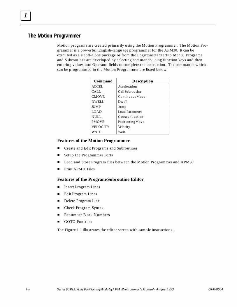
The Motion Programmer
Motion programs are created primarily using the Motion Programmer. The Motion Pro-grammer is a powerful, English-language programmer for the APM30. It can beexecuted as a stand-alone package or from the Logicmaster Startup Menu. Programsand Subroutines are developed by selecting commands using function keys and thenentering values into Operand fields to complete the instruction. The commands whichcan be programmed in the Motion Programmer are listed below.
ÁÁÁÁÁÁÁÁÁÁ
CommandÁÁÁÁÁÁÁÁÁÁÁÁÁÁÁÁÁÁÁÁ
Description
ÁÁÁÁÁACCEL ÁÁÁÁÁÁÁÁÁÁAccelerationÁÁÁÁÁÁÁÁÁÁCALL
ÁÁÁÁÁÁÁÁÁÁÁÁÁÁÁÁÁÁÁÁCall SubroutineÁÁÁÁÁ
ÁÁÁÁÁCMOVE
ÁÁÁÁÁÁÁÁÁÁÁÁÁÁÁÁÁÁÁÁ
Continuous MoveÁÁÁÁÁÁÁÁÁÁ
DWELL ÁÁÁÁÁÁÁÁÁÁÁÁÁÁÁÁÁÁÁÁ
DwellÁÁÁÁÁÁÁÁÁÁ
JUMP ÁÁÁÁÁÁÁÁÁÁÁÁÁÁÁÁÁÁÁÁ
Jump
ÁÁÁÁÁÁÁÁÁÁ
LOAD ÁÁÁÁÁÁÁÁÁÁÁÁÁÁÁÁÁÁÁÁ
Load Parameter
ÁÁÁÁÁÁÁÁÁÁ
NULL ÁÁÁÁÁÁÁÁÁÁÁÁÁÁÁÁÁÁÁÁ
Causes no actionÁÁÁÁÁÁÁÁÁÁPMOVE
ÁÁÁÁÁÁÁÁÁÁÁÁÁÁÁÁÁÁÁÁPositioning MoveÁÁÁÁÁ
ÁÁÁÁÁVELOCITY
ÁÁÁÁÁÁÁÁÁÁÁÁÁÁÁÁÁÁÁÁ
VelocityÁÁÁÁÁÁÁÁÁÁ
WAIT ÁÁÁÁÁÁÁÁÁÁÁÁÁÁÁÁÁÁÁÁ
Wait
Features of the Motion Programmer
� Create and Edit Programs and Subroutines
� Setup the Programmer Ports
� Load and Store Program files between the Motion Programmer and APM30
� Print APM30 Files
Features of the Program/Subroutine Editor
� Insert Program Lines
� Edit Program Lines
� Delete Program Line
� Check Program Syntax
� Renumber Block Numbers
� GOTO Function
The Figure 1-1 illustrates the editor screen with sample instructions.
1
1-3GFK-0664 Chapter 1 Introduction to APM Programming
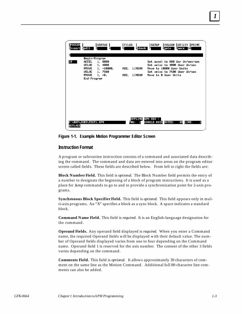
Figure 1-1. Example Motion Programmer Editor Screen
Instruction Format
A program or subroutine instruction consists of a command and associated data describ-ing the command. The command and data are entered into areas on the program editorscreen called fields. These fields are described below. From left to right the fields are:
Block Number Field. This field is optional. The Block Number field permits the entry ofa number to designate the beginning of a block of program instructions. It is used as aplace for Jump commands to go to and to provide a synchronization point for 2-axis pro-grams.
Synchronous Block Specifier Field. This field is optional. This field appears only in mul-ti-axis programs. An “X” specifies a block as a sync block. A space indicates a standardblock.
Command Name Field. This field is required. It is an English-language designation forthe command.
Operand Fields. Any operand field displayed is required. When you enter a Commandname, the required Operand fields will be displayed with their default value. The num-ber of Operand fields displayed varies from one to four depending on the Commandname. Operand field 1 is reserved for the axis number. The content of the other 3 fieldsvaries depending on the command.
Comments Field. This field is optional. It allows approximately 30 characters of com-ment on the same line as the Motion Command. Additional full 80-character line com-ments can also be added.
1
1-4 Series 90 PLC Axis Positioning Module (APM) Programmer’s Manual - August 1993 GFK-0664
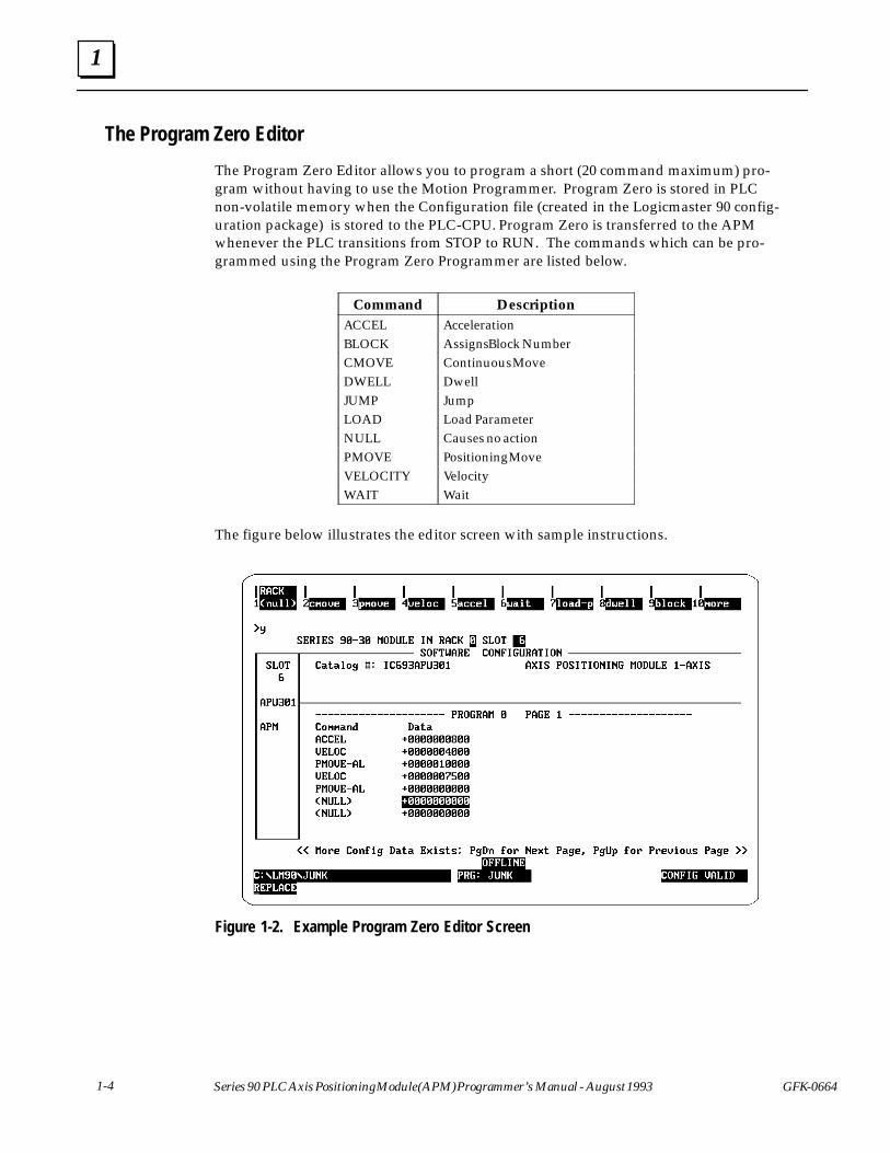
The Program Zero Editor
The Program Zero Editor allows you to program a short (20 command maximum) pro-gram without having to use the Motion Programmer. Program Zero is stored in PLCnon-volatile memory when the Configuration file (created in the Logicmaster 90 config-uration package) is stored to the PLC-CPU. Program Zero is transferred to the APMwhenever the PLC transitions from STOP to RUN. The commands which can be pro-grammed using the Program Zero Programmer are listed below.
ÁÁÁÁÁÁÁÁÁÁ
CommandÁÁÁÁÁÁÁÁÁÁÁÁÁÁÁÁÁÁÁÁ
Description
ÁÁÁÁÁACCEL ÁÁÁÁÁÁÁÁÁÁAccelerationÁÁÁÁÁÁÁÁÁÁBLOCK
ÁÁÁÁÁÁÁÁÁÁÁÁÁÁÁÁÁÁÁÁAssigns Block NumberÁÁÁÁÁ
ÁÁÁÁÁCMOVE
ÁÁÁÁÁÁÁÁÁÁÁÁÁÁÁÁÁÁÁÁ
Continuous MoveÁÁÁÁÁÁÁÁÁÁ
DWELL ÁÁÁÁÁÁÁÁÁÁÁÁÁÁÁÁÁÁÁÁ
DwellÁÁÁÁÁÁÁÁÁÁ
JUMP ÁÁÁÁÁÁÁÁÁÁÁÁÁÁÁÁÁÁÁÁ
Jump
ÁÁÁÁÁÁÁÁÁÁ
LOAD ÁÁÁÁÁÁÁÁÁÁÁÁÁÁÁÁÁÁÁÁ
Load Parameter
ÁÁÁÁÁÁÁÁÁÁ
NULL ÁÁÁÁÁÁÁÁÁÁÁÁÁÁÁÁÁÁÁÁ
Causes no actionÁÁÁÁÁÁÁÁÁÁPMOVE
ÁÁÁÁÁÁÁÁÁÁÁÁÁÁÁÁÁÁÁÁPositioning MoveÁÁÁÁÁ
ÁÁÁÁÁVELOCITY
ÁÁÁÁÁÁÁÁÁÁÁÁÁÁÁÁÁÁÁÁ
VelocityÁÁÁÁÁÁÁÁÁÁ
WAIT ÁÁÁÁÁÁÁÁÁÁÁÁÁÁÁÁÁÁÁÁ
Wait
The figure below illustrates the editor screen with sample instructions.
Figure 1-2. Example Program Zero Editor Screen
1
1-5GFK-0664 Chapter 1 Introduction to APM Programming
Instruction Format
A Program Zero instruction consists of a command and associated data describing thecommand. The command and data are entered into areas on the program editor screencalled fields. These fields are described below. From left to right the fields are:
Command Name Field. It is an English-language designation for the command. To en-ter a command, position the cursor on a command name field then press the desiredFunction key (F1-F10). Most of the commands fall into groups such as CMOVE, PMOVE,VELOC, ACCEL, etc. The variations of these commands can be displayed after you pressthe Function key for the particular group. To display the JUMP command, first press theF10 more Function key.
For example, if you want to program a CMOVE-IS-P (Continuous Move, Incremental,S-Curve, using a parameter), first move to a command field, then press the cmove func-tion key. This causes CMOVE-AL to be displayed in the command name field of thescreen. Press the Tab key to cycle through all the variations of the command.
Operand Fields. Paired with each command is a data field,. and, if you are configuring a2-axis APM, an axis number field. In the data field you enter either a signed integer orthe number of an APM parameter, as appropriate for the configured command.

2 section level 1 1figure bi level 1 table_big level 1
2-1GFK-0664
Chapter 2 Motion Programmer
The Motion Programmer software package is a powerful, English-language programmerfor the APM. Motion programs are developed using English-language commands se-lected through function keys. This reduces programming time and makes the programsyou create easy to follow. The APM Motion Programmer operates much like the otherpackages in Logicmaster 90 Programming Software.
This chapter describes how to use all the features of the Motion Programmer. The chap-ter is divided into the following sections.
� Section 1. Starting-Up the Motion Programmer
� Section 2. Creating and Editing Programs and Subroutines
� Section 3. Status Functions
� Section 4. Using APM Files and Folders
� Section 5. Setting-Up the Programmer Ports
� Section 6. Loading and Storing APM Files
� Section 7. Printing APM Files
Note
The purpose of this chapter is to familiarize you with the procedures forentering motion commands and with the other editor functions. For adetailed description of how each command works, etc. refer toAppendix A, The APM Motion Commands.

2
2-2 Series 90 Axis Positioning Module (APM) Programmer’s Manual - August 1993 GFK-0664
Section 1: Starting-Up the Motion Programmer
The Motion Programmer can be executed as a stand-alone package or as part of the Lo-gicmaster 90 Programming Software.
This section covers the following main topics.
� Installing the Motion Programmer Software
� Starting-Up the Motion Programmer
� The Motion Programmer Main Screen (Function and Status Line Descriptions)
Installing the Motion Programmer Software
Before starting the installation procedure, you may wish to create backups for the cur-rent CONFIG.SYS file and AUTOEXEC.BAT file. The installation software will modifythese files for you automatically if you so choose.
To install the Motion Programmer Software:
1. Insert the Motion Programmer software diskette into Drive A or another drive if de-sired.
2. From the prompt of the drive containing the Motion Programmer diskette, type.
A:\> install
3. A screen appears prompting you to enter the destination hard drive for the MotionProgrammer software. Enter the drive letter (or use the default drive that is pro-vided) and press Enter.
4. If this is the first installation of the software, a screen for registering the softwareappears. This screen contains prompts for your name, company, address, and soft-ware serial number. Fill in this information.
Note
The serial number for your software is located on the back of diskettenumber 1.
After you have entered the information, press Enter.
5. A screen for confirming the registration information appears next. If the informa-tion you entered is correct, press Enter. If it is not, press Esc to correct any informa-tion. If you pressed Enter the data is then written onto the master distribution disk.
6. The Copyright screen then appears. Press Enter to continue.
7. The AUTOEXEC.BAT and CONFIG.SYS modification screen appears next. Press Y ifyou want the Install program to automatically modify these files for optimum opera-
2
2-3GFK-0664 Chapter 2 Motion Programmer
tion of the Motion Programmer software. Press N if you want to modify the filesyourself.
8. If you pressed Y, the Install program will create an LM90 directory on the hard driveyou specified, and write the Motion Programmer software to it.
If you pressed N, so you could modify the files yourself, a screen will appearprompting you to make the modifications shown below after installing the software.A confirm prompt also appears at the bottom of this screen which permits you tochange your mind and have the Install program modify the AUTOEXEC.BAT andthe CONFIG.SYS files. Press Y for automatic update or press N if you still want tomodify them yourself. In either case, the Motion Programmer files will be installedon your hard disk at this time.
To the AUTOEXEC.BAT file, add the following to the path line.
(Drive ID):\LM90
The Drive ID is the letter corresponding to the hard disk drive where the MotionProgrammer software is installed.
To the CONFIG.SYS file, make the following entries.
FILES = 20BUFFERS = 15
9. After the Install program writes all the files to the destination drive, the Motion Pro-grammer software is installed. If you elected to modify the AUTOEXEC.BAT andCONFIG.SYS files yourself, do so now.
10. Press Ctrl-Alt-Delete to reboot your computer and activate the new AUTOEX-EC.BAT and CONFIG.SYS files.
2
2-4 Series 90 Axis Positioning Module (APM) Programmer’s Manual - August 1993 GFK-0664
Starting-Up the Motion Programmer
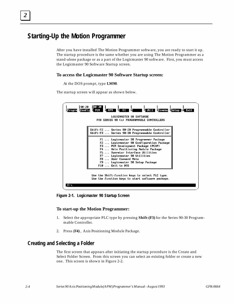
After you have installed The Motion Programmer software, you are ready to start it up.The startup procedure is the same whether you are using The Motion Programmer as astand-alone package or as a part of the Logicmaster 90 software. First, you must accessthe Logicmaster 90 Software Startup screen.
To access the Logicmaster 90 Software Startup screen:
At the DOS prompt, type LM90.
The startup screen will appear as shown below.
Figure 2-1. Logicmaster 90 Startup Screen
To start-up the Motion Programmer:
1. Select the appropriate PLC type by pressing Shift-(F3) for the Series 90-30 Program-mable Controller.
2. Press (F4) , Axis Positioning Module Package.
Creating and Selecting a Folder
The first screen that appears after initiating the startup procedure is the Create andSelect Folder Screen. From this screen you can select an existing folder or create a newone. This screen is shown in Figure 2-2.

2
2-5GFK-0664 Chapter 2 Motion Programmer
Figure 2-2. Startup Folder Selection Screen
A folder is the next to the highest of a four level hierarchy for organizing your work. It isthe highest level that can be created or selected within the Motion Programmer and cancontain PLC ladder programs, Configuration files, and APM files. The hierarchy is asfollows.
ÁÁÁÁÁÁÁÁLevel
ÁÁÁÁÁÁÁÁÁÁÁÁÁÁÁÁÁÁNameÁÁÁÁ
ÁÁÁÁFirst
ÁÁÁÁÁÁÁÁÁÁÁÁÁÁÁÁÁÁ
DrawerÁÁÁÁÁÁÁÁ
Second ÁÁÁÁÁÁÁÁÁÁÁÁÁÁÁÁÁÁ
FolderÁÁÁÁÁÁÁÁ
Third ÁÁÁÁÁÁÁÁÁÁÁÁÁÁÁÁÁÁ
APM File
ÁÁÁÁFourth ÁÁÁÁÁÁÁÁÁPrograms and Subroutines
Detailed descriptions of the hierarchy are found in Section 4. Using Folders and Files.
Note
The folders displayed on this screen correspond to the product typespecified for the Motion Programmer. If the product type is the Series90-30, then only Series 90-30 folders will be displayed. If the producttype is the 90-70, then only Series 90-70 folders will be displayed. If nofolders exist for either package, a message such as “No folders exist” willbe displayed in the folder window.
To continue the start-up procedure, a folder must exist and be selected or you mustcreate a new folder if none exists.
To create a Folder:
1. Type-in a new folder name in the folder field. The folder name can be no longerthan 7 characters, otherwise use the same DOS conventions as used for naming sub-directories.
2
2-6 Series 90 Axis Positioning Module (APM) Programmer’s Manual - August 1993 GFK-0664
2. Press Enter.
3. A prompt will appear to confirm the creation of a new folder. Press “Y” to confirm.(Confirming the operation will create a new folder and it will be the selected folder). The APM File Selection screen will then appear.
If the create folder procedure is successful, the newly created folder becomes the cur-rently selected folder.
If the create folder procedure is not successful, an appropriate error message will be dis-played. You can either try again or exit the Motion Programmer by pressing the Esc key.
To select an existing Folder:
1. Type in an existing folder name or use the Cursor keys and the PgUp/PgDn keys toposition the cursor on the desired folder in the boxed in area.
2. Press Enter.
If the folder selected already contains files, the APM File Selection screen is bypassed andthe Main Motion Programmer screen appears. The Motion Programmer automaticallyselects a file and program/subroutine for you based on the following rules.
First choice: The APM file and program/subroutine last edited by the user as long as thecurrently selected folder matches the previously selected folder.
Second choice: The first alphabetical APM file in the folder. In this case the default pro-gram selection is Program 1.
2
2-7GFK-0664 Chapter 2 Motion Programmer
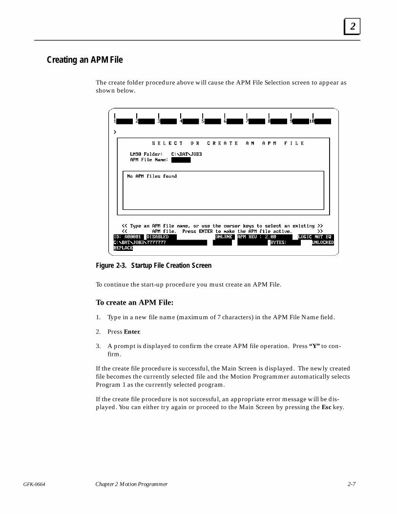
Creating an APM File
The create folder procedure above will cause the APM File Selection screen to appear asshown below.
Figure 2-3. Startup File Creation Screen
To continue the start-up procedure you must create an APM File.
To create an APM File:
1. Type in a new file name (maximum of 7 characters) in the APM File Name field.
2. Press Enter.
3. A prompt is displayed to confirm the create APM file operation. Press “Y” to con-firm.
If the create file procedure is successful, the Main Screen is displayed. The newly createdfile becomes the currently selected file and the Motion Programmer automatically selectsProgram 1 as the currently selected program.
If the create file procedure is not successful, an appropriate error message will be dis-played. You can either try again or proceed to the Main Screen by pressing the Esc key.
2
2-8 Series 90 Axis Positioning Module (APM) Programmer’s Manual - August 1993 GFK-0664
The Motion Programmer Main Screen
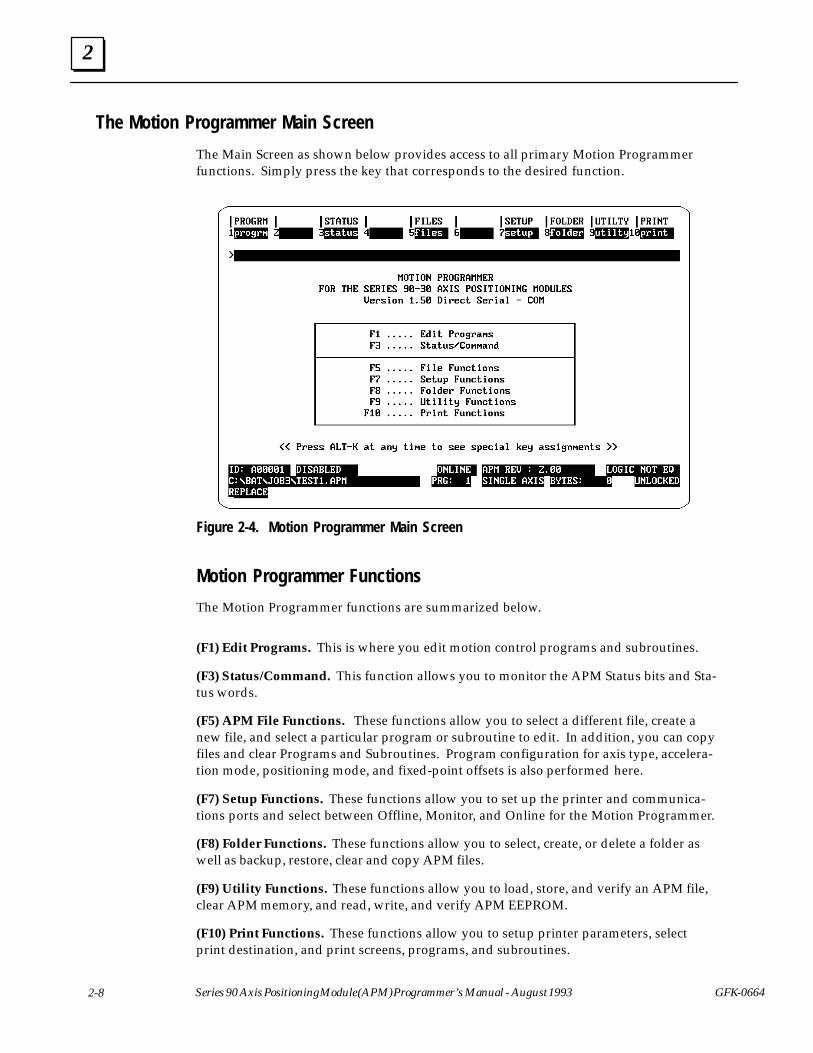
The Main Screen as shown below provides access to all primary Motion Programmerfunctions. Simply press the key that corresponds to the desired function.
Figure 2-4. Motion Programmer Main Screen
Motion Programmer Functions
The Motion Programmer functions are summarized below.
(F1) Edit Programs. This is where you edit motion control programs and subroutines.
(F3) Status/Command. This function allows you to monitor the APM Status bits and Sta-tus words.
(F5) APM File Functions. These functions allow you to select a different file, create anew file, and select a particular program or subroutine to edit. In addition, you can copyfiles and clear Programs and Subroutines. Program configuration for axis type, accelera-tion mode, positioning mode, and fixed-point offsets is also performed here.
(F7) Setup Functions. These functions allow you to set up the printer and communica-tions ports and select between Offline, Monitor, and Online for the Motion Programmer.
(F8) Folder Functions. These functions allow you to select, create, or delete a folder aswell as backup, restore, clear and copy APM files.
(F9) Utility Functions. These functions allow you to load, store, and verify an APM file,clear APM memory, and read, write, and verify APM EEPROM.
(F10) Print Functions. These functions allow you to setup printer parameters, selectprint destination, and print screens, programs, and subroutines.
2
2-9GFK-0664 Chapter 2 Motion Programmer
Message LineNear the top of the screen below the function keys is the message line. This line iswhere user prompts and system messages appear.
Command Line
The Command Line is identified by the “>” symbol in the upper left-hand corner of thescreen. It is used for the GoTo and Renumber functions in the Program Editor.
Status Line Definition
There are three lines at the bottom of the screen which contain information about thestatus of the Motion Programmer. Status line information may differ somewhat depend-ing on the screen you are in. Many of these screens, however, contain common fieldswhich will always be displayed. Both common and unique fields are described here.
When the programmer mode is Off-Line, the status lines show information relating tothe selected drawer, folder, file, and program/subroutine, the programmer mode, andthe keyboard setup. When the programmer mode is Monitor or On-Line, the status ofcommunications between the programmer and APM, and the logic equality between theselected file and the file in the APM are also displayed.
Status Line 1
SNP ID Field. It shows the SNP ID (if any) of the connected APM. This field is knownas an MOC field because it appears only when The Motion Programmer is:
� In Monitor or Online modes, and
� Connected with the APM
Enabled/Disabled/Invalid Field. This MOC field shows the Enabled/Disabled state ofthe APM. Invalid APM is displayed if connected to a non-APM device. For example, ifyou are connected directly to the PLC instead of the APM, Invalid APM will be dis-played.
No Communications Field. This field appears when The Motion Programmer is in ei-ther Monitor or On-line mode, and the APM is not communicating with the programmer.It will appear in place of the SNP ID field and the Enabled/Disabled field.
Programmer Mode Field. This field is displayed at all times. It shows whether the modeis Offline, Monitor, or On-Line.
Software Revision Field. This field displays the software revision level of the APM.
Logic Equality Field. This an MOC field. It shows whether the program logic on disk isequal to the logic in the APM.
Status Line 2
Selected File Field. This field is displayed at all times. It shows the current APM file se-lected for The Motion Programmer. In folder screens, only the selected folder is dis-played.
2
2-10 Series 90 Axis Positioning Module (APM) Programmer’s Manual - August 1993 GFK-0664
Prg/Sub Number Field. This field is displayed on many different status line configura-tions, but not all of them. It shows the selected program or subroutine number.
Prg/Sub Type Field. This field is displayed on many different status line configurations,but not all of them. It shows the selected program or subroutine axis type (whether it issingle or multi-axis).
Bytes. This field displays the total of the number of bytes used by the selected program/subroutine. Displayed only on some screens.
Line Number. This field keeps track of the current line you are on within the selectedprogram/subroutine. Displayed in the editor only.
Folder Locked/Unlocked Field. Displays the current folder locked or unlocked status.Only displayed in folder and file functions. When locked, no writes are allowed to thefolder.
Status Line 3
Insert/Replace. Displays whether the keyboard is in the insert text or the replace textmode.
CAPS. Displays the keyboard Caps Lock status. May be toggled on and off by pressingthe Caps Lock key. Default state is off.
NUM. Displays the keyboard Num Lock status. May be toggled on and off by pressingthe Num Lock key. Default state is off.
Help and Special Function Keys
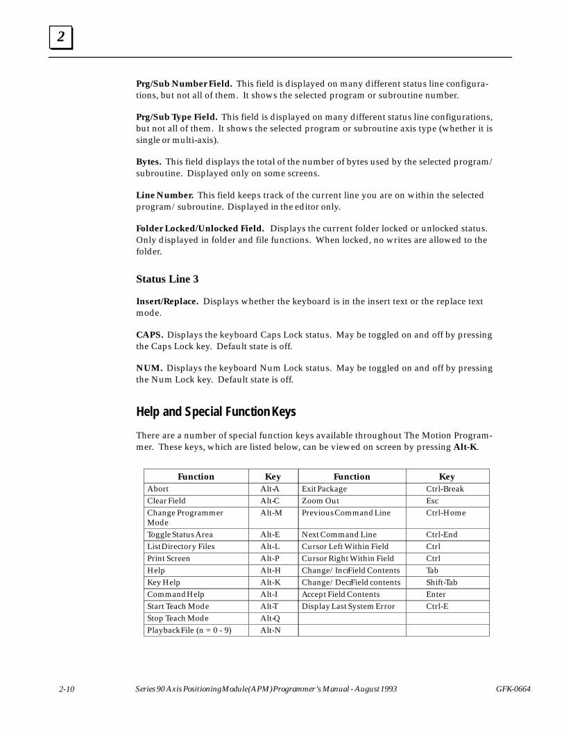
There are a number of special function keys available throughout The Motion Program-mer. These keys, which are listed below, can be viewed on screen by pressing Alt-K.
ÁÁÁÁÁÁÁÁÁÁÁÁÁÁÁÁ
Function ÁÁÁÁÁÁÁÁÁÁ
Key ÁÁÁÁÁÁÁÁÁÁÁÁÁÁÁÁ
Function ÁÁÁÁÁÁÁÁÁÁÁÁÁÁ
Key
ÁÁÁÁÁÁÁÁAbort ÁÁÁÁÁAlt-A ÁÁÁÁÁÁÁÁExit Package ÁÁÁÁÁÁÁCtrl-BreakÁÁÁÁÁÁÁÁÁÁÁÁÁÁÁÁClear Field
ÁÁÁÁÁÁÁÁÁÁAlt-C
ÁÁÁÁÁÁÁÁÁÁÁÁÁÁÁÁZoom Out
ÁÁÁÁÁÁÁÁÁÁÁÁÁÁEscÁÁÁÁÁÁÁÁ
ÁÁÁÁÁÁÁÁÁÁÁÁÁÁÁÁ
Change ProgrammerMode
ÁÁÁÁÁÁÁÁÁÁÁÁÁÁÁ
Alt-MÁÁÁÁÁÁÁÁÁÁÁÁÁÁÁÁÁÁÁÁÁÁÁÁ
Previous Command LineÁÁÁÁÁÁÁÁÁÁÁÁÁÁÁÁÁÁÁÁÁ
Ctrl-Home
ÁÁÁÁÁÁÁÁÁÁÁÁÁÁÁÁ
Toggle Status Area ÁÁÁÁÁÁÁÁÁÁ
Alt-E ÁÁÁÁÁÁÁÁÁÁÁÁÁÁÁÁ
Next Command Line ÁÁÁÁÁÁÁÁÁÁÁÁÁÁ
Ctrl-End
ÁÁÁÁÁÁÁÁList Directory Files ÁÁÁÁÁAlt-L ÁÁÁÁÁÁÁÁCursor Left Within Field ÁÁÁÁÁÁÁCtrlÁÁÁÁÁÁÁÁÁÁÁÁÁÁÁÁPrint Screen
ÁÁÁÁÁÁÁÁÁÁAlt-P
ÁÁÁÁÁÁÁÁÁÁÁÁÁÁÁÁCursor Right Within Field
ÁÁÁÁÁÁÁÁÁÁÁÁÁÁCtrlÁÁÁÁÁÁÁÁ
ÁÁÁÁÁÁÁÁHelp
ÁÁÁÁÁÁÁÁÁÁ
Alt-HÁÁÁÁÁÁÁÁÁÁÁÁÁÁÁÁ
Change/Incr Field ContentsÁÁÁÁÁÁÁÁÁÁÁÁÁÁ
TabÁÁÁÁÁÁÁÁÁÁÁÁÁÁÁÁ
Key Help ÁÁÁÁÁÁÁÁÁÁ
Alt-K ÁÁÁÁÁÁÁÁÁÁÁÁÁÁÁÁ
Change/Decr Field contentsÁÁÁÁÁÁÁÁÁÁÁÁÁÁ
Shift-TabÁÁÁÁÁÁÁÁÁÁÁÁÁÁÁÁ
Command Help ÁÁÁÁÁÁÁÁÁÁ
Alt-I ÁÁÁÁÁÁÁÁÁÁÁÁÁÁÁÁ
Accept Field Contents ÁÁÁÁÁÁÁÁÁÁÁÁÁÁ
Enter
ÁÁÁÁÁÁÁÁÁÁÁÁÁÁÁÁ
Start Teach Mode ÁÁÁÁÁÁÁÁÁÁ
Alt-T ÁÁÁÁÁÁÁÁÁÁÁÁÁÁÁÁ
Display Last System ErrorÁÁÁÁÁÁÁÁÁÁÁÁÁÁ
Ctrl-E
ÁÁÁÁÁÁÁÁÁÁÁÁÁÁÁÁ
Stop Teach Mode ÁÁÁÁÁÁÁÁÁÁ
Alt-Q ÁÁÁÁÁÁÁÁÁÁÁÁÁÁÁÁ
ÁÁÁÁÁÁÁÁÁÁÁÁÁÁ
ÁÁÁÁÁÁÁÁÁÁÁÁÁÁÁÁPlayback File (n = 0 - 9)
ÁÁÁÁÁÁÁÁÁÁAlt-N
ÁÁÁÁÁÁÁÁÁÁÁÁÁÁÁÁ
ÁÁÁÁÁÁÁÁÁÁÁÁÁÁ
2
2-11GFK-0664 Chapter 2 Motion Programmer
Establishing Communications Between the APM and Programmer
Some Motion Programmer operations require the Motion Programmer to be physicallyconnected and communicating with the APM. Refer to Section 5, Setting-Up the Ports.to establish communications between the Motion Programmer and the APM.
2
2-12 Series 90 Axis Positioning Module (APM) Programmer’s Manual - August 1993 GFK-0664
Section 2. Creating and Editing Programs and Subroutines
This section describes the features of the Motion Program Editor. The editor allows youto display and edit a program and provides a number of other functions to make motionprogramming easier. Topics covered in this section are:
� Displaying a Program
� Inserting Program Lines
� Making Changes to a Line
� Deleting a Line
� Checking Program Syntax
� Renumbering Block Numbers
� Using the GOTO Function
� APM Command List
� Size Limitations
Displaying a Program
Press (F1) Edit Programs at the Main screen to enter the Motion Programmer Editor.The editor is in Display Mode at this time, and the currently selected program or subrou-tine is displayed. The currently selected file and program or subroutine are identified inStatus Line 2.
To Display a Different Program or Subroutine:
1. If you want to work with a program or subroutine in a different folder or file, youmust go to the File functions, press Shift (F5) or Folder functions, press Shift (F8),and select the desired folder, file, and program or subroutine, then re-enter the edi-tor, press Shift (F1).
2. If you want to work with a different program or subroutine in the same folder andfile, press (F8) goto, enter the program or subroutine number in the Command Line,then press Enter.
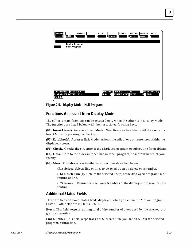
If you have not yet entered any lines in a program, it is known as a null program. A nullprogram is displayed in Figure 2-5.
2
2-13GFK-0664 Chapter 2 Motion Programmer
Figure 2-5. Display Mode - Null Program
Functions Accessed from Display Mode
The editor’s main functions can be accessed only when the editor is in Display Mode.The functions are listed below with their associated function keys.
(F1) Insert Line(s). Accesses Insert Mode. New lines can be added until the user exitsInsert Mode by pressing the Esc key.
(F2) Edit Line(s). Accesses Edit Mode. Allows the edit of one or more lines within thedisplayed screen.
(F6) Check. Checks the structure of the displayed program or subroutine for problems.
(F8) Goto. Goes to the block number, line number, program, or subroutine which youspecify.
(F9) More. Provides access to other edit functions described below.
(F1) Select. Selects line or lines to be acted upon by delete or renumber.
(F6) Delete Line(s). Deletes the selected line(s) of the displayed program/sub-routine or line.
(F7) Renum. Renumbers the Block Numbers of the displayed program or sub-routine.
Additional Status FieldsThere are two additional status fields displayed when you are in the Motion ProgramEditor. Both fields are in Status Line 2.
Bytes. This field keeps a running total of the number of bytes used by the selected pro-gram/subroutine.
Line Number. This field keeps track of the current line you are on within the selectedprogram/subroutine.
2
2-14 Series 90 Axis Positioning Module (APM) Programmer’s Manual - August 1993 GFK-0664
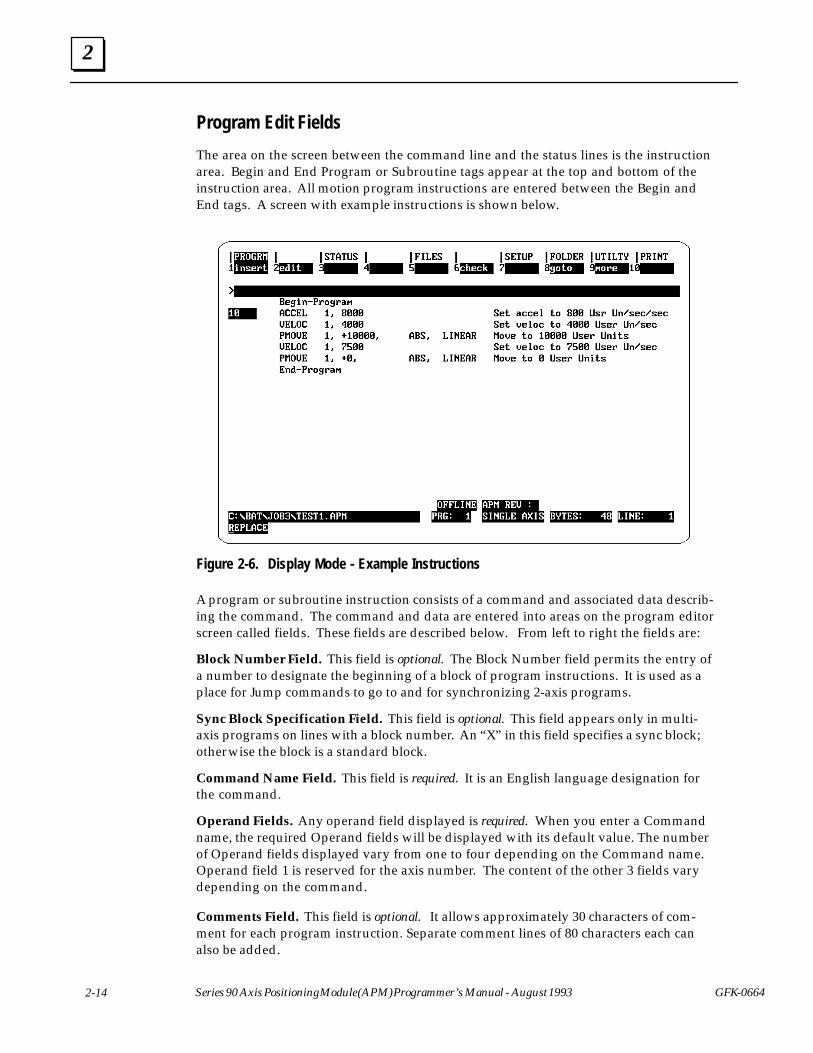
Program Edit Fields
The area on the screen between the command line and the status lines is the instructionarea. Begin and End Program or Subroutine tags appear at the top and bottom of theinstruction area. All motion program instructions are entered between the Begin andEnd tags. A screen with example instructions is shown below.
Figure 2-6. Display Mode - Example Instructions
A program or subroutine instruction consists of a command and associated data describ-ing the command. The command and data are entered into areas on the program editorscreen called fields. These fields are described below. From left to right the fields are:
Block Number Field. This field is optional. The Block Number field permits the entry ofa number to designate the beginning of a block of program instructions. It is used as aplace for Jump commands to go to and for synchronizing 2-axis programs.
Sync Block Specification Field. This field is optional. This field appears only in multi-axis programs on lines with a block number. An “X” in this field specifies a sync block;otherwise the block is a standard block.
Command Name Field. This field is required. It is an English language designation forthe command.
Operand Fields. Any operand field displayed is required. When you enter a Commandname, the required Operand fields will be displayed with its default value. The numberof Operand fields displayed vary from one to four depending on the Command name.Operand field 1 is reserved for the axis number. The content of the other 3 fields varydepending on the command.
Comments Field. This field is optional. It allows approximately 30 characters of com-ment for each program instruction. Separate comment lines of 80 characters each canalso be added.
2
2-15GFK-0664 Chapter 2 Motion Programmer
Moving the CursorWhile in Display Mode you are allowed to move vertically through a displayed program.The cursor will always be positioned on the first field of the selected line. The cursor canbe moved horizontally from field to field in Insert and Edit Modes.
� Up Arrow - Moves cursor up one line.
� Down Arrow - Moves cursor down one line.
� PgUp - Moves cursor up one page.
� PgDn - Moves cursor down one page.
� Home - Moves cursor to beginning of Program or Subroutine.
� End - Moves the cursor to the end of Program or Subroutine.
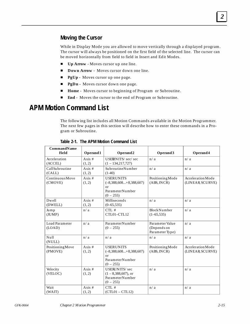
APM Motion Command List
The following list includes all Motion Commands available in the Motion Programmer.The next few pages in this section will describe how to enter these commands in a Pro-gram or Subroutine.
Table 2-1. The APM Motion Command List
ÁÁÁÁÁÁÁÁÁÁÁÁÁÁ
Command NameField
ÁÁÁÁÁÁÁÁOperand 1
ÁÁÁÁÁÁÁÁÁÁÁÁÁÁÁÁOperand 2
ÁÁÁÁÁÁÁÁÁÁÁÁÁÁOperand 3
ÁÁÁÁÁÁÁÁÁÁÁÁOperand 4ÁÁÁÁÁÁÁ
ÁÁÁÁÁÁÁÁÁÁÁÁÁÁ
Acceleration(ACCEL)
ÁÁÁÁÁÁÁÁÁÁÁÁ
Axis #(1, 2)
ÁÁÁÁÁÁÁÁÁÁÁÁÁÁÁÁÁÁÁÁÁÁÁÁ
USER UNITS/sec/sec(1 – 134,217,727)
ÁÁÁÁÁÁÁÁÁÁÁÁÁÁÁÁÁÁÁÁÁ
n/aÁÁÁÁÁÁÁÁÁÁÁÁÁÁÁÁÁÁ
n/a
ÁÁÁÁÁÁÁÁÁÁÁÁÁÁ
Call Subroutine(CALL)
ÁÁÁÁÁÁÁÁAxis #(1, 2)
ÁÁÁÁÁÁÁÁÁÁÁÁÁÁÁÁ
Subroutine Number(1-40)
ÁÁÁÁÁÁÁÁÁÁÁÁÁÁ
n/a ÁÁÁÁÁÁÁÁÁÁÁÁ
n/a
ÁÁÁÁÁÁÁÁÁÁÁÁÁÁÁÁÁÁÁÁÁÁÁÁÁÁÁÁÁÁÁÁÁÁÁ
Continuous Move(CMOVE)
ÁÁÁÁÁÁÁÁÁÁÁÁÁÁÁÁÁÁÁÁ
Axis #(1, 2)
ÁÁÁÁÁÁÁÁÁÁÁÁÁÁÁÁÁÁÁÁÁÁÁÁÁÁÁÁÁÁÁÁÁÁÁÁÁÁÁÁ
USER UNITS(–8,388,608...+8,388,607)orParameter Number(0 – 255)
ÁÁÁÁÁÁÁÁÁÁÁÁÁÁÁÁÁÁÁÁÁÁÁÁÁÁÁÁÁÁÁÁÁÁÁ
Positioning Mode(ABS, INCR)
ÁÁÁÁÁÁÁÁÁÁÁÁÁÁÁÁÁÁÁÁÁÁÁÁÁÁÁÁÁÁ
Acceleration Mode(LINEAR, SCURVE)
ÁÁÁÁÁÁÁÁÁÁÁÁÁÁÁÁÁÁÁÁÁ
Dwell(DWELL)
ÁÁÁÁÁÁÁÁÁÁÁÁ
Axis #(1, 2)
ÁÁÁÁÁÁÁÁÁÁÁÁÁÁÁÁÁÁÁÁÁÁÁÁ
Milliseconds(0–65,535)
ÁÁÁÁÁÁÁÁÁÁÁÁÁÁÁÁÁÁÁÁÁ
n/a ÁÁÁÁÁÁÁÁÁÁÁÁÁÁÁÁÁÁ
n/a
ÁÁÁÁÁÁÁÁÁÁÁÁÁÁÁÁÁÁÁÁÁÁÁÁÁÁÁÁ
Jump(JUMP)
ÁÁÁÁÁÁÁÁÁÁÁÁÁÁÁÁ
n/aÁÁÁÁÁÁÁÁÁÁÁÁÁÁÁÁÁÁÁÁÁÁÁÁÁÁÁÁÁÁÁÁ
CTL #CTL01–CTL12
ÁÁÁÁÁÁÁÁÁÁÁÁÁÁÁÁÁÁÁÁÁÁÁÁÁÁÁÁ
Block Number(1–65,535)
ÁÁÁÁÁÁÁÁÁÁÁÁÁÁÁÁÁÁÁÁÁÁÁÁ
n/a
ÁÁÁÁÁÁÁÁÁÁÁÁÁÁÁÁÁÁÁÁÁ
Load Parameter(LOAD)
ÁÁÁÁÁÁÁÁÁÁÁÁ
n/a ÁÁÁÁÁÁÁÁÁÁÁÁÁÁÁÁÁÁÁÁÁÁÁÁ
Parameter Number(0 – 255)
ÁÁÁÁÁÁÁÁÁÁÁÁÁÁÁÁÁÁÁÁÁ
Parameter Value(Depends onParameter Type)
ÁÁÁÁÁÁÁÁÁÁÁÁÁÁÁÁÁÁ
n/a
ÁÁÁÁÁÁÁÁÁÁÁÁÁÁ
Null(NULL)
ÁÁÁÁÁÁÁÁn/a ÁÁÁÁÁÁÁÁ
ÁÁÁÁÁÁÁÁn/a ÁÁÁÁÁÁÁ
ÁÁÁÁÁÁÁn/a ÁÁÁÁÁÁ
ÁÁÁÁÁÁn/a
ÁÁÁÁÁÁÁÁÁÁÁÁÁÁÁÁÁÁÁÁÁÁÁÁÁÁÁÁÁÁÁÁÁÁÁ
Positioning Move(PMOVE)
ÁÁÁÁÁÁÁÁÁÁÁÁÁÁÁÁÁÁÁÁ
Axis #(1, 2)
ÁÁÁÁÁÁÁÁÁÁÁÁÁÁÁÁÁÁÁÁÁÁÁÁÁÁÁÁÁÁÁÁÁÁÁÁÁÁÁÁ
USER UNITS(–8,388,608...+8,388,607)orParameter Number(0 – 255)
ÁÁÁÁÁÁÁÁÁÁÁÁÁÁÁÁÁÁÁÁÁÁÁÁÁÁÁÁÁÁÁÁÁÁÁ
Positioning Mode(ABS, INCR)
ÁÁÁÁÁÁÁÁÁÁÁÁÁÁÁÁÁÁÁÁÁÁÁÁÁÁÁÁÁÁ
Acceleration Mode(LINEAR, SCURVE)
ÁÁÁÁÁÁÁÁÁÁÁÁÁÁÁÁÁÁÁÁÁÁÁÁÁÁÁÁ
Velocity(VELOC)
ÁÁÁÁÁÁÁÁÁÁÁÁÁÁÁÁ
Axis #(1, 2)
ÁÁÁÁÁÁÁÁÁÁÁÁÁÁÁÁÁÁÁÁÁÁÁÁÁÁÁÁÁÁÁÁ
USER UNITS/sec(1 – 8,388,607), orParameter Number(0 – 255)
ÁÁÁÁÁÁÁÁÁÁÁÁÁÁÁÁÁÁÁÁÁÁÁÁÁÁÁÁ
n/a ÁÁÁÁÁÁÁÁÁÁÁÁÁÁÁÁÁÁÁÁÁÁÁÁ
n/a
ÁÁÁÁÁÁÁÁÁÁÁÁÁÁ
Wait(WAIT)
ÁÁÁÁÁÁÁÁAxis #(1, 2)
ÁÁÁÁÁÁÁÁÁÁÁÁÁÁÁÁ
CTL #(CTL01 – CTL12)
ÁÁÁÁÁÁÁÁÁÁÁÁÁÁ
n/a ÁÁÁÁÁÁÁÁÁÁÁÁ
n/a
2
2-16 Series 90 Axis Positioning Module (APM) Programmer’s Manual - August 1993 GFK-0664
Inserting Lines in a Program or Subroutine
When you are programming a new program or subroutine or if you want to add lines toan existing program, you must enter the Insert Line Mode. The procedure below de-scribes how to enter Insert Line Mode and insert a new line.
While connected and in the Online or Monitor mode, Motion Programmer allows inser-tions only up to the maximum program memory size of the currently communicatingAPM. This limit is for the sum of all 10 programs and subroutines. To insert lines beyondthis limit, either change to Offline mode or connect to an APM with more programmemory.
To enter Insert Mode:
1. If you are inserting lines in a null program/subroutine, Press the (F1) insert key.
2. If you are inserting a line(s) to an existing program, determine the insertion point ofthe new line(s), position the cursor on the line below the insertion point. Then pressthe (F1) insert key.
The function keys displayed at the top of the screen will change to reflect only the cur-rent options available. As you enter Insert Mode, the cursor remains on the Block Num-ber.
To add an APM Command line(s):
1. Enter a Block Number if desired ( 1– 65,535). This field is optional. It is recom-mended to make Block Numbers sequential for fastest program execution, but it isnot required. Block Numbers must be unique.
2. Move the cursor to the Command Name field by pressing the Enter or Right Arrowkey.
3. Enter the Command by pressing the appropriate function key or by typing it in andpressing Enter.
4. This will cause the applicable operand fields for the command to be displayed.Some commands have only two operands such as the Velocity command, others haveas many as four operands such as the Move commands.
� Default attributes for each operand will be displayed when possible.
� Operands requiring input will display a “?”.
� Enter an appropriate value for each Operand by typing it in or, using the Tabkey to display the desired selection or, when possible, by selecting theappropriate function key and pressing Enter.
� Press Enter to bypass an Operand.
� For more information on valid ranges for operands see Table 2-1.
Note
You can set default attributes for Acceleration Mode (Linear, Scurve),Positioning Mode (Absolute, Incremental), and Fixed Point formats inthe Program and Subroutine Selection screens of the File functions.
2
2-17GFK-0664 Chapter 2 Motion Programmer
5. If you wish to enter a comment, move the cursor to the Comment field and type inyour comment.
6. At this point you have three options.
� Press the Esc key to accept the instruction and return to Display Mode.
� Press the Enter or Down Arrow key to accept the instruction and to openanother line below the previously inserted line and remain in Insert Mode.
� Press the Up Arrow key to accept the instruction and to open a line above thepreviously entered line and remain in Insert Mode.
Note
The adding or editing of a line may be aborted at any time by pressingthe Alt/A key sequence. If you have not changed any field in the line,aborting will return you to Display Mode. If you have made changes,aborting will cause a prompt to be displayed asking you to confirm theabort. If you confirm, the line is cleared and the cursor returns to thebeginning of the line. If you do not confirm, the cursor remains at itscurrent position.
To add a Comment line(s):
You can add a separate comment line of up to 80 characters by typing a semicolonfollowed by the comment.
Making Changes to a Program or Subroutine
To make changes to an existing line or lines of a program or subroutine you must enterthe Edit Mode. Most Edit Mode operations are the same as for Insert Mode, and thescreens are the same except that a line within the program or subroutine is not openedin Edit Mode as it is in Insert Mode.
To enter the Edit Mode:
1. Position the cursor on the line to edit.
2. Press the F2 edit key.
To change an entry in a line:
1. Position the cursor on the field you want to change.
2. Type in or select the new entry in the same manner as for Insert Mode.
2
2-18 Series 90 Axis Positioning Module (APM) Programmer’s Manual - August 1993 GFK-0664
3. At this point you have three options.
� Press the Esc key to accept the change and return to Display Mode.
� Press the Enter or Down Arrow key to accept the change and to move to theline below and remain in Edit Mode.
� Press the Up Arrow key to accept the change and to move to the line above andremain in Edit Mode.
Deleting a Line
The Delete Line function is executed in Display Mode only. There are two basic ways todelete a line.
To delete one line at a time:
1. Position the cursor on the line to be deleted.
2. Press the Alt-D key sequence. A confirmation prompt will be displayed. If you en-ter a Y, the line will be deleted. If you enter an N, the function will be aborted.
To delete multiple lines:
1. Press the (F9) more key so that the (F1) select key is displayed.
2. Position the cursor on one boundary of the lines you want to delete.
3. Press the (F1) select key.
4. Move the cursor down or up to include all lines you want to delete. The lines youselect will be shown in reverse video.
5. Press the Alt-D key sequence or the (F6) delete key. A confirmation prompt will bedisplayed. If you enter a Y, the lines will be deleted. If you enter an N, the functionwill be aborted.
Checking Program or Subroutine Syntax
Each instruction you enter is checked to prevent you from entering invalid data. TheCheck Syntax function provides a check of the structure of the overall program or sub-routine. The Check Syntax function tests the following conditions.
� Jump to unknown Block Number (Fatal)
� Call to an undefined subroutine (Fatal)
� Recursive subroutine call (Fatal)
� Block Number out of sequence (Warning)
2
2-19GFK-0664 Chapter 2 Motion Programmer
To execute the Check Syntax function:
1. Press (F6) check when in Display Mode.
2. These checks are also made when you exit Display Mode to go to the editor’s MainMenu by pressing the Esc key.
In either case of executing the Check Syntax function, a message will appear if a struc-tural problem is found. The message will state the type of syntax error and the corre-sponding line number. Press any key to continue.
Renumbering Block Numbers
You can renumber the Block Numbers within selected lines. You can also specify theincrement value of the Block Numbers.
To renumber Block Numbers:
1. Press the (F9) more key so that the (F1) select key is displayed.
2. Position the cursor on one boundary of the Block Numbers you want to renumber.
3. Press the (F1) select key.
4. Move the cursor down or up to include all Block Numbers you want to renumber.
5. Press the (F7) renum key. This will renumber all Block Numbers within the selectedlines by an increment of 10.
Or, first place an increment value in the command line before pressing the (F7) re-num key.
Using the GoTo Function
You may go to a specific block number or line number within the current program or sub-routine using the GoTo function. You can also use this function to select a different pro-gram or subroutine within the current APM File.
To use the GoTo function:
1. Enter the GoTo destination in the command line.
Block numbers are not preceded by a symbol.Line numbers are preceded by the “#” symbol.Program numbers are preceded by the “%” symbol.Subroutine numbers are preceded by the “$” symbol.
2. Press the (F8) goto key.
If the Block Number is found, the cursor will be placed at the beginning of the line con-taining the Block Number. If the Block Number is not found, the cursor will not moveand an error message will be displayed. If the line number is greater than the number oflines in the program, the cursor will move to the last line of the program.
2
2-20 Series 90 Axis Positioning Module (APM) Programmer’s Manual - August 1993 GFK-0664
Size Limitations
When the Motion Programmer is On-Line and communicating with an APM, it will notallow a file to grow larger than the program memory limit of the APM. The file size isthe sum of all 10 program and 40 subroutine sizes and can be seen in the Store screenunder Utilities. For Release 1 APMs, this limit is 16 K Bytes. For Release 2, the limit is 14K Bytes.
If the Motion Programmer is Off-Line or not communicating, APM memory limitationswill not apply to generating a program. However, limits will apply when an attempt tostore the file is made.
2
2-21GFK-0664 Chapter 2 Motion Programmer
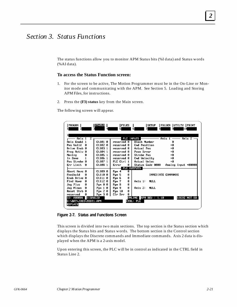
Section 3. Status Functions
The status functions allow you to monitor APM Status bits (%I data) and Status words(%AI data).
To access the Status Function screen:
1. For the screen to be active, The Motion Programmer must be in the On-Line or Mon-itor mode and communicating with the APM. See Section 5. Loading and StoringAPM Files, for instructions.
2. Press the (F3) status key from the Main screen.
The following screen will appear.
Figure 2-7. Status and Functions Screen
This screen is divided into two main sections. The top section is the Status section whichdisplays the Status bits and Status words. The bottom section is the Control sectionwhich displays the Discrete commands and Immediate commands. Axis 2 data is dis-played when the APM is a 2-axis model.
Upon entering this screen, the PLC will be in control as indicated in the CTRL field inStatus Line 2.

2
2-22 Series 90 Axis Positioning Module (APM) Programmer’s Manual - August 1993 GFK-0664
Section 4. Using APM Files and Folders
This section describes the features available in the APM File Functions (F5) and the Fold-er Functions (F8). The topics in this section are organized as follows.
� Hierarchy of Folders and Files
� APM File Functions
� Folder Functions
Hierarchy of Folders and FilesThe Motion Programmer permits a hierarchical storage of APM Programs andSubroutines to help you organize your work. APM Programs and Subroutines are storedin APM Files. APM Files are stored within Folders. And Folders are stored withinDrawers. This storage hierarchy is described below.
ÁÁÁÁÁÁÁÁÁÁÁÁÁÁÁÁÁÁÁÁÁÁÁÁÁÁÁÁ
Drawer ÁÁÁÁÁÁÁÁÁÁÁÁÁÁÁÁÁÁÁÁÁÁÁÁÁÁÁÁÁÁÁÁÁÁÁÁÁÁÁÁÁÁÁÁÁÁÁÁÁÁÁÁÁÁÁÁÁÁÁÁÁÁÁÁÁÁÁÁÁÁÁÁÁÁÁÁÁÁÁÁ
Highest level DOS directory for storing Logicmaster Folders.The default Drawer is \LM90. New Drawers must be createdoutside the Motion Programmer using the DOS Make Directo-ry (mkdir) command. For example, C:\> mkdir motor1
ÁÁÁÁÁÁÁÁÁÁÁÁÁÁÁÁÁÁÁÁÁÁÁÁÁÁÁÁÁÁÁÁÁÁÁ
Folder ÁÁÁÁÁÁÁÁÁÁÁÁÁÁÁÁÁÁÁÁÁÁÁÁÁÁÁÁÁÁÁÁÁÁÁÁÁÁÁÁÁÁÁÁÁÁÁÁÁÁÁÁÁÁÁÁÁÁÁÁÁÁÁÁÁÁÁÁÁÁÁÁÁÁÁÁÁÁÁÁÁÁÁÁÁÁÁÁÁÁÁÁÁÁÁÁÁÁÁÁ
DOS subdirectory within a Drawer used for organizing filesspecific to an application., must be created by the Logicmaster90 software or the Motion Programmer software. APM Files aswell as Logicmaster program and configuration files can all ex-ist in the same Folder.
ÁÁÁÁÁÁÁÁÁÁÁÁÁÁÁÁÁÁÁÁÁÁÁÁÁÁÁÁ
APM File ÁÁÁÁÁÁÁÁÁÁÁÁÁÁÁÁÁÁÁÁÁÁÁÁÁÁÁÁÁÁÁÁÁÁÁÁÁÁÁÁÁÁÁÁÁÁÁÁÁÁÁÁÁÁÁÁÁÁÁÁÁÁÁÁÁÁÁÁÁÁÁÁÁÁÁÁÁÁÁÁ
DOS File which contains APM programs, subroutines, andcomments. Created only in the Motion Programmer. APMProgram and Subroutine Files have an .APM extension; Com-ment Files have a .CMT extension..
ÁÁÁÁÁÁÁÁÁÁÁÁÁÁÁÁÁÁÁÁÁÁÁÁÁÁÁÁ
APM Programs andSubroutines
ÁÁÁÁÁÁÁÁÁÁÁÁÁÁÁÁÁÁÁÁÁÁÁÁÁÁÁÁÁÁÁÁÁÁÁÁÁÁÁÁÁÁÁÁÁÁÁÁÁÁÁÁÁÁÁÁÁÁÁÁÁÁÁÁÁÁÁÁÁÁÁÁÁÁÁÁÁÁÁÁ
There are 10 APM Programs numbered 1-10 and 40 APM Sub-routines numbered 1-40 which always exist within each APMFile. The Programs and Subroutines are empty until edited.
2
2-23GFK-0664 Chapter 2 Motion Programmer
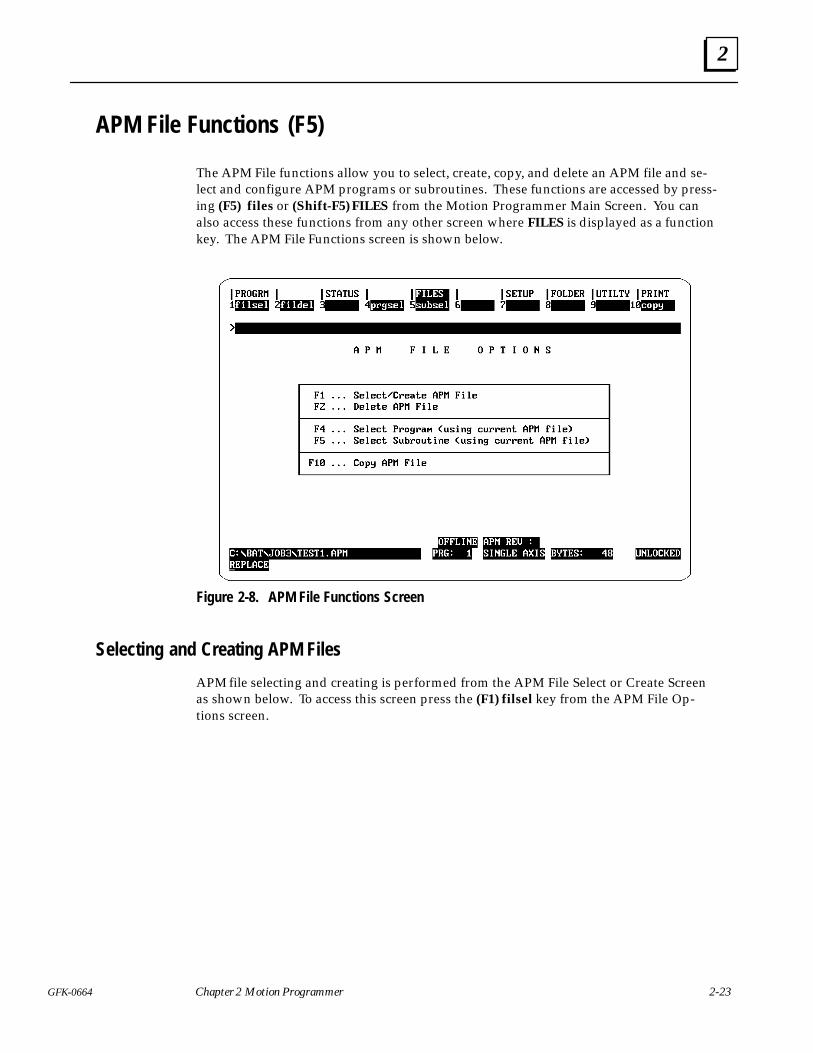
APM File Functions (F5)
The APM File functions allow you to select, create, copy, and delete an APM file and se-lect and configure APM programs or subroutines. These functions are accessed by press-ing (F5) files or (Shift-F5) FILES from the Motion Programmer Main Screen. You canalso access these functions from any other screen where FILES is displayed as a functionkey. The APM File Functions screen is shown below.
Figure 2-8. APM File Functions Screen
Selecting and Creating APM Files
APM file selecting and creating is performed from the APM File Select or Create Screenas shown below. To access this screen press the (F1) filsel key from the APM File Op-tions screen.
2
2-24 Series 90 Axis Positioning Module (APM) Programmer’s Manual - August 1993 GFK-0664
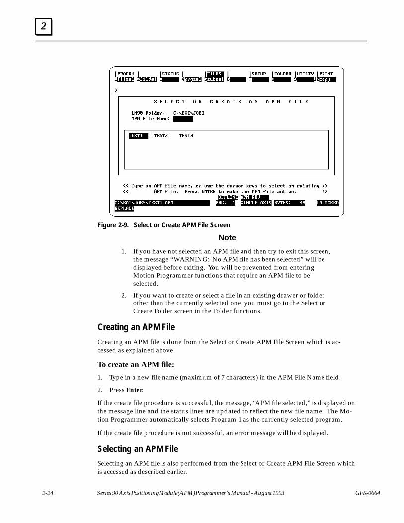
Figure 2-9. Select or Create APM File Screen
Note
1. If you have not selected an APM file and then try to exit this screen,the message “WARNING: No APM file has been selected” will bedisplayed before exiting. You will be prevented from enteringMotion Programmer functions that require an APM file to beselected.
2. If you want to create or select a file in an existing drawer or folderother than the currently selected one, you must go to the Select orCreate Folder screen in the Folder functions.
Creating an APM File
Creating an APM file is done from the Select or Create APM File Screen which is ac-cessed as explained above.
To create an APM file:
1. Type in a new file name (maximum of 7 characters) in the APM File Name field.
2. Press Enter.
If the create file procedure is successful, the message, “APM file selected,” is displayed onthe message line and the status lines are updated to reflect the new file name. The Mo-tion Programmer automatically selects Program 1 as the currently selected program.
If the create file procedure is not successful, an error message will be displayed.
Selecting an APM FileSelecting an APM file is also performed from the Select or Create APM File Screen whichis accessed as described earlier.
2
2-25GFK-0664 Chapter 2 Motion Programmer
To select an APM file:
1. Type in an existing file name in the file name field or use the Cursor keys and thePgUp/PgDn keys to position the cursor on the desired file in the boxed-in area.
2. Press Enter.
If the select file procedure is successful, the message, “APM file selected,” will be displayedon the message line and the status lines will be updated to reflect the new file name. TheMotion Programmer automatically selects Program 1 as the currently selected program.
If the select file procedure is not successful, an error message will be displayed. You caneither try selecting the same file again or another file.
Once a file has been successfully selected, you can return to the APM File Options screenby pressing the Esc key or you can move directly to another File function by pressingthe appropriate function key.
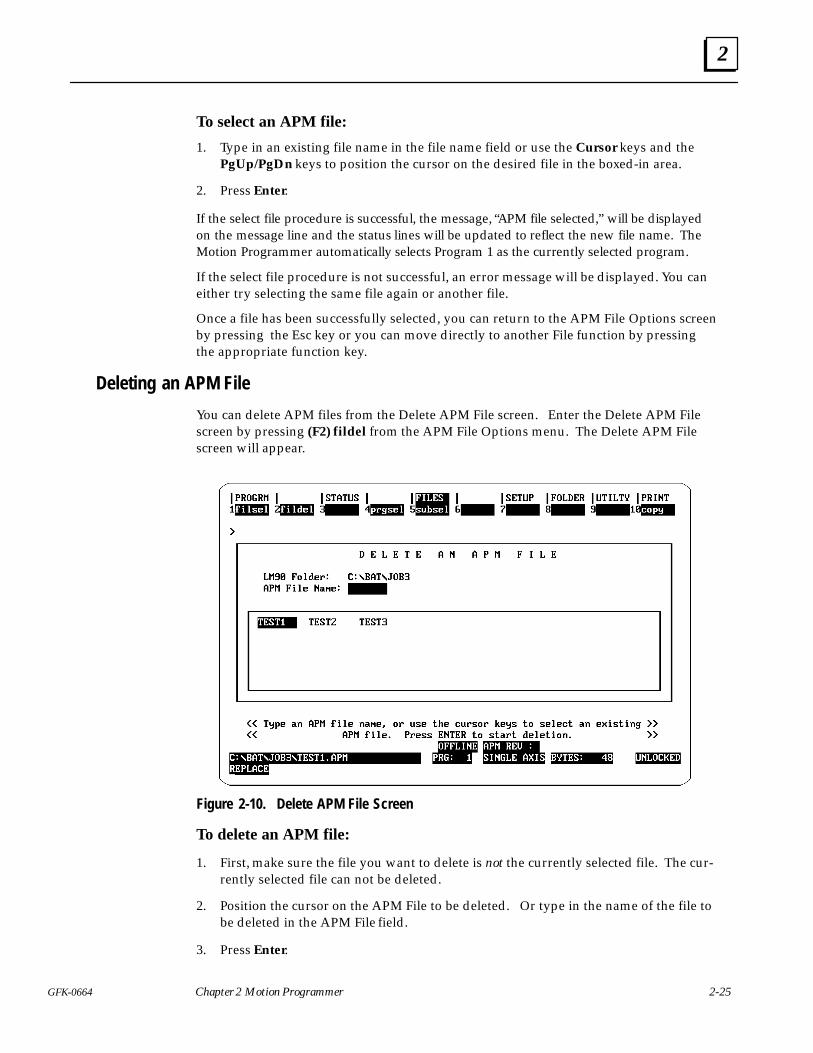
Deleting an APM File
You can delete APM files from the Delete APM File screen. Enter the Delete APM Filescreen by pressing (F2) fildel from the APM File Options menu. The Delete APM Filescreen will appear.
Figure 2-10. Delete APM File Screen
To delete an APM file:
1. First, make sure the file you want to delete is not the currently selected file. The cur-rently selected file can not be deleted.
2. Position the cursor on the APM File to be deleted. Or type in the name of the file tobe deleted in the APM File field.
3. Press Enter.
2
2-26 Series 90 Axis Positioning Module (APM) Programmer’s Manual - August 1993 GFK-0664
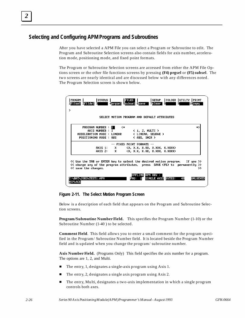
Selecting and Configuring APM Programs and Subroutines
After you have selected a APM File you can select a Program or Subroutine to edit. TheProgram and Subroutine Selection screens also contain fields for axis number, accelera-tion mode, positioning mode, and fixed point formats.
The Program or Subroutine Selection screens are accessed from either the APM File Op-tions screen or the other file functions screens by pressing (F4) prgsel or (F5) subsel. Thetwo screens are nearly identical and are discussed below with any differences noted.The Program Selection screen is shown below.
Figure 2-11. The Select Motion Program Screen
Below is a description of each field that appears on the Program and Subroutine Selec-tion screens.
Program/Subroutine Number Field. This specifies the Program Number (1-10) or theSubroutine Number (1-40 ) to be selected.
Comment Field. This field allows you to enter a small comment for the program speci-fied in the Program/Subroutine Number field. It is located beside the Program Numberfield and is updated when you change the program/subroutine number.
Axis Number Field. (Programs Only) This field specifies the axis number for a program.The options are 1, 2, and Multi.
� The entry, 1, designates a single-axis program using Axis 1.
� The entry, 2, designates a single axis program using Axis 2.
� The entry, Multi, designates a two-axis implementation in which a single programcontrols both axes.
2
2-27GFK-0664 Chapter 2 Motion Programmer
Type Field. (Subroutines Only) This field designates whether the subroutine will be asingle or multi-axis subroutine. A multi-axis subroutine can only be called from multi-axis programs. A single-axis subroutine can only be called by single-axis programs.
Acceleration Mode Field. This field specifies the default acceleration mode, Linear orS-Curve.
Positioning Mode Field. This field specifies the default positioning mode, Absolute orIncremental.
Fixed Point Format Field. The fixed point offset is a user convenience which applies tocommands specifying position, velocity, and acceleration. A program can have differentfixed point offsets for each axis in a 2-axis module. Fixed point offsets do not apply to theDwell command, which is specified in milliseconds, nor does it apply to parameters (P0 ...P255) since parameters can be used for more than one axis. The examples below showwhat values would appear on the screen for a fixed point offset of x.xx.
� Enter 20399; result on the screen is 20339.00
� Enter 2033.9; result on the screen is 2033.90
� Enter 20.339; result on the screen is 20.33
� Enter 20.33; result on the screen is 20.33
If your servo system has a gearing ratio of 1000 counts = 1 mm, you might want to selecta fixed point format of x.xxx. This would allow you to program 1.000 for a distance of 1mm.
If your servo system has a gearing ratio of 100 counts = 1 inch, you might want to selecta fixed point format of x.xx. This would allow you to program 1.00 for a distance of 1inch.
To select a program or subroutine:
1. From the Select Program or Subroutine screen, use the Cursor keys to position thecursor on the program or subroutine number field.
2. Step through the program or subroutine numbers using the Tab key until you findthe desired program or subroutine number. Each time you press the Tab key, thedisplayed program or subroutine is selected and the attribute fields will be updated.
Or, type in the desired number in the Program or Subroutine field, and press Enterto select. The attribute fields will then be updated.
To set default attributes for a program or subroutine:
1. From the Select Program or Subroutine screen, use the Cursor keys position the cur-sor on the appropriate attribute field.
2. Step through the options for the fields using the Tab key until the desired option isdisplayed. Or, type in the desired option in the field. You may also press Alt-A torestore the fields to their previous values.
3. Press (F6) save, to save the attributes.
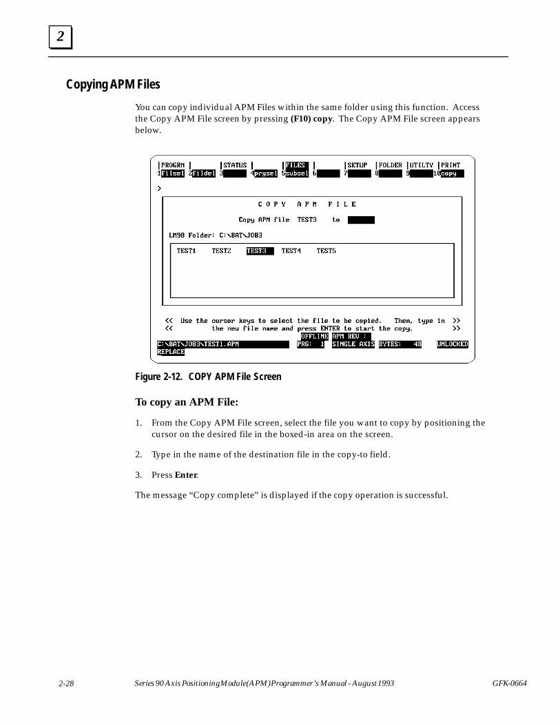
2
2-28 Series 90 Axis Positioning Module (APM) Programmer’s Manual - August 1993 GFK-0664
Copying APM Files
You can copy individual APM Files within the same folder using this function. Accessthe Copy APM File screen by pressing (F10) copy. The Copy APM File screen appearsbelow.
Figure 2-12. COPY APM File Screen
To copy an APM File:
1. From the Copy APM File screen, select the file you want to copy by positioning thecursor on the desired file in the boxed-in area on the screen.
2. Type in the name of the destination file in the copy-to field.
3. Press Enter.
The message “Copy complete” is displayed if the copy operation is successful.
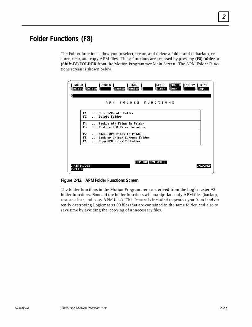
2
2-29GFK-0664 Chapter 2 Motion Programmer
Folder Functions (F8)
The Folder functions allow you to select, create, and delete a folder and to backup, re-store, clear, and copy APM files. These functions are accessed by pressing (F8) folder or(Shift-F8) FOLDER from the Motion Programmer Main Screen. The APM Folder Func-tions screen is shown below.
Figure 2-13. APM Folder Functions Screen
The folder functions in the Motion Programmer are derived from the Logicmaster 90folder functions. Some of the folder functions will manipulate only APM files (backup,restore, clear, and copy APM files). This feature is included to protect you from inadver-tently destroying Logicmaster 90 files that are contained in the same folder, and also tosave time by avoiding the copying of unnecessary files.
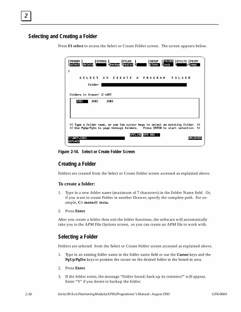
2
2-30 Series 90 Axis Positioning Module (APM) Programmer’s Manual - August 1993 GFK-0664
Selecting and Creating a Folder
Press F1 select to access the Select or Create Folder screen. The screen appears below.
Figure 2-14. Select or Create Folder Screen
Creating a Folder
Folders are created from the Select or Create Folder screen accessed as explained above.
To create a folder:
1. Type in a new folder name (maximum of 7 characters) in the Folder Name field. Or,if you want to create Folder in another Drawer, specify the complete path. For ex-ample, C:\motor1\testa.
2. Press Enter.
After you create a folder then exit the folder functions, the software will automaticallytake you to the APM File Options screen, so you can create an APM file to work with.
Selecting a Folder
Folders are selected from the Select or Create Folder screen accessed as explained above.
1. Type in an existing folder name in the folder name field or use the Cursor keys and thePgUp/PgDn keys to position the cursor on the desired folder in the boxed-in area.
2. Press Enter.
3. If the folder exists, the message “Folder found; back up its contents?” will appear.Enter “Y” if you desire to backup the folder.
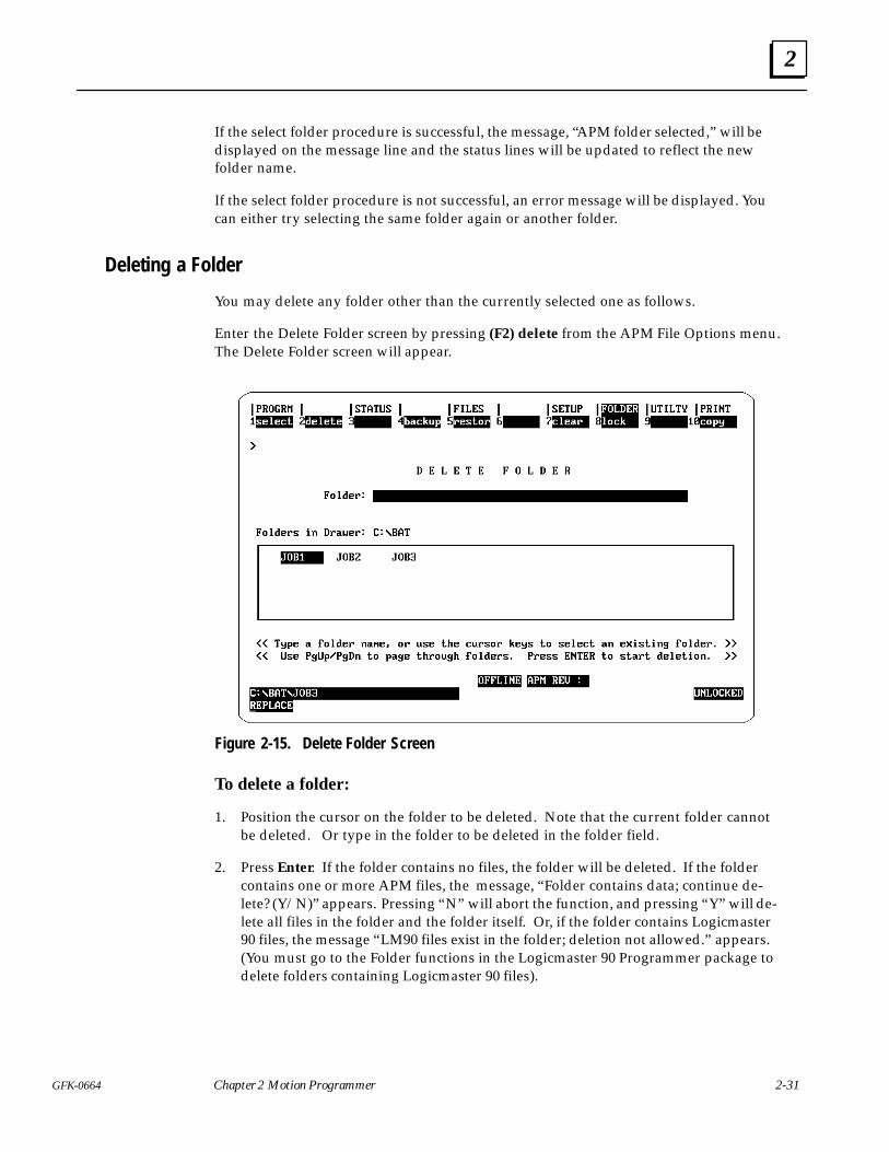
2
2-31GFK-0664 Chapter 2 Motion Programmer
If the select folder procedure is successful, the message, “APM folder selected,” will bedisplayed on the message line and the status lines will be updated to reflect the newfolder name.
If the select folder procedure is not successful, an error message will be displayed. Youcan either try selecting the same folder again or another folder.
Deleting a Folder
You may delete any folder other than the currently selected one as follows.
Enter the Delete Folder screen by pressing (F2) delete from the APM File Options menu.The Delete Folder screen will appear.
Figure 2-15. Delete Folder Screen
To delete a folder:
1. Position the cursor on the folder to be deleted. Note that the current folder cannotbe deleted. Or type in the folder to be deleted in the folder field.
2. Press Enter. If the folder contains no files, the folder will be deleted. If the foldercontains one or more APM files, the message, “Folder contains data; continue de-lete? (Y/N)” appears. Pressing “N” will abort the function, and pressing “Y” will de-lete all files in the folder and the folder itself. Or, if the folder contains Logicmaster90 files, the message “LM90 files exist in the folder; deletion not allowed.” appears.(You must go to the Folder functions in the Logicmaster 90 Programmer package todelete folders containing Logicmaster 90 files).

2
2-32 Series 90 Axis Positioning Module (APM) Programmer’s Manual - August 1993 GFK-0664
Backing-Up All APM Files in a Folder
All APM files in the selected folder can be backed up. To enter the Backup screen, press(F4) backup from the main Folder Functions screen or any of the other Folder sub-screens. The Backup screen is shown below.
Figure 2-16. Backup Folder Screen
The default backup directory is a subdirectory under the folder subdirectory selected.You may choose your own backup directory by typing in the desired path in the backupdestination field.
To backup the files of the selected folder:
1. Use the default destination or enter your own backup destination..
2. Press Enter.
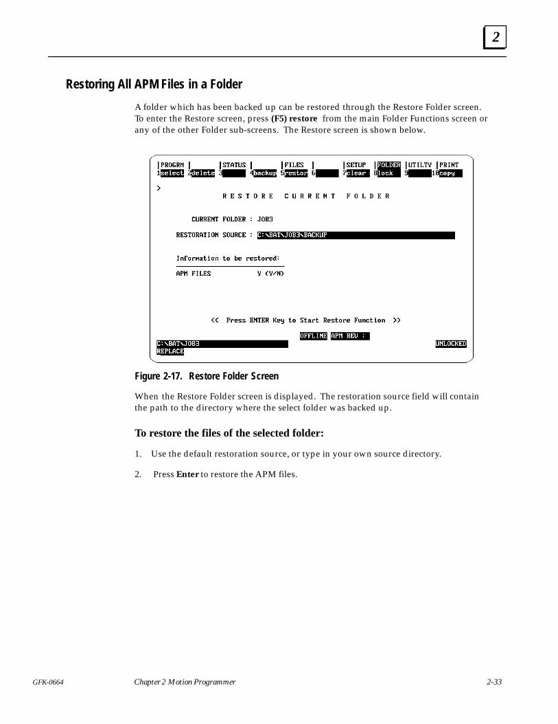
2
2-33GFK-0664 Chapter 2 Motion Programmer
Restoring All APM Files in a Folder
A folder which has been backed up can be restored through the Restore Folder screen.To enter the Restore screen, press (F5) restore from the main Folder Functions screen orany of the other Folder sub-screens. The Restore screen is shown below.
Figure 2-17. Restore Folder Screen
When the Restore Folder screen is displayed. The restoration source field will containthe path to the directory where the select folder was backed up.
To restore the files of the selected folder:
1. Use the default restoration source, or type in your own source directory.
2. Press Enter to restore the APM files.
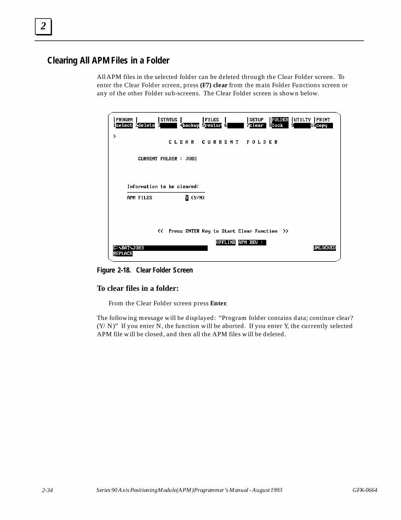
2
2-34 Series 90 Axis Positioning Module (APM) Programmer’s Manual - August 1993 GFK-0664
Clearing All APM Files in a Folder
All APM files in the selected folder can be deleted through the Clear Folder screen. Toenter the Clear Folder screen, press (F7) clear from the main Folder Functions screen orany of the other Folder sub-screens. The Clear Folder screen is shown below.
Figure 2-18. Clear Folder Screen
To clear files in a folder:
From the Clear Folder screen press Enter.
The following message will be displayed: “Program folder contains data; continue clear?(Y/N)” If you enter N, the function will be aborted. If you enter Y, the currently selectedAPM file will be closed, and then all the APM files will be deleted.
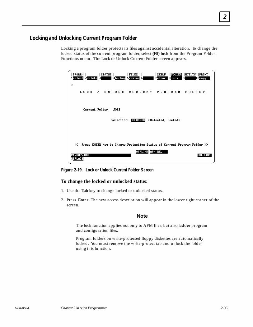
2
2-35GFK-0664 Chapter 2 Motion Programmer
Locking and Unlocking Current Program Folder
Locking a program folder protects its files against accidental alteration. To change thelocked status of the current program folder, select (F8) lock from the Program FolderFunctions menu. The Lock or Unlock Current Folder screen appears.
Figure 2-19. Lock or Unlock Current Folder Screen
To change the locked or unlocked status:
1. Use the Tab key to change locked or unlocked status.
2. Press Enter. The new access description will appear in the lower right corner of thescreen.
Note
The lock function applies not only to APM files, but also ladder programand configuration files.
Program folders on write-protected floppy diskettes are automaticallylocked. You must remove the write-protect tab and unlock the folderusing this function.

2
2-36 Series 90 Axis Positioning Module (APM) Programmer’s Manual - August 1993 GFK-0664
Copying All APM Files in a Folder
All APM files in a source folder can be copied to the selected folder through the CopyFolder screen. To enter the Copy Folder screen, press (F10) copy from the main FolderFunctions screen or any of the other Folder sub-screens. The Copy Folder screen ap-pears.
Figure 2-20. Copy Folder Screen
To copy files from one folder to another:
1. Before entering the Copy Folder screen, select the folder to which you wish to copythe files. Then enter the Copy Folder screen by pressing the (F10) copy key.
2. Enter the path name of the source folder in the source folder field.
Example: C:\LM90\JOB2 if JOB2 is in a different drawer than the current folder.
Example: JOB2 if JOB2 is in the same drawer as the current folder.
3. Press Enter to copy the APM files to the current folder.
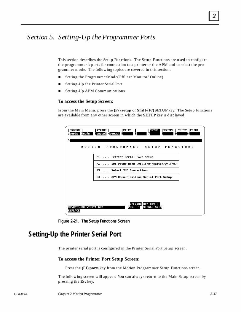
2
2-37GFK-0664 Chapter 2 Motion Programmer
Section 5. Setting-Up the Programmer Ports
This section describes the Setup Functions. The Setup Functions are used to configurethe programmer’s ports for connection to a printer or the APM and to select the pro-grammer mode. The following topics are covered in this section.
� Setting the Programmer Mode (Offline/Monitor/Online)
� Setting-Up the Printer Serial Port
� Setting-Up APM Communications
To access the Setup Screen:
From the Main Menu, press the (F7) setup or Shift-(F7) SETUP key. The Setup functionsare available from any other screen in which the SETUP key is displayed.
Figure 2-21. The Setup Functions Screen
Setting-Up the Printer Serial Port
The printer serial port is configured in the Printer Serial Port Setup screen.
To access the Printer Port Setup Screen:
Press the (F1) ports key from the Motion Programmer Setup Functions screen.
The following screen will appear. You can always return to the Main Setup screen bypressing the Esc key.
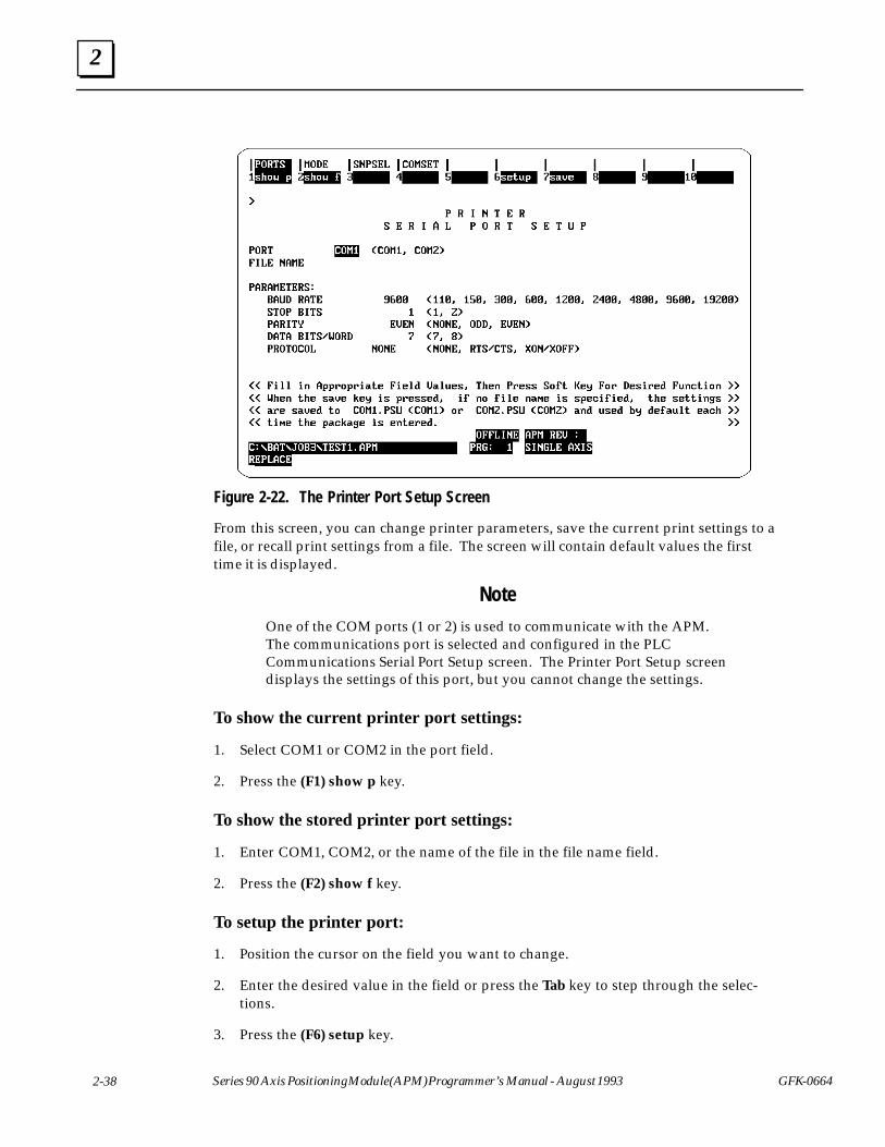
2
2-38 Series 90 Axis Positioning Module (APM) Programmer’s Manual - August 1993 GFK-0664
Figure 2-22. The Printer Port Setup Screen
From this screen, you can change printer parameters, save the current print settings to afile, or recall print settings from a file. The screen will contain default values the firsttime it is displayed.
NoteOne of the COM ports (1 or 2) is used to communicate with the APM.The communications port is selected and configured in the PLCCommunications Serial Port Setup screen. The Printer Port Setup screendisplays the settings of this port, but you cannot change the settings.
To show the current printer port settings:
1. Select COM1 or COM2 in the port field.
2. Press the (F1) show p key.
To show the stored printer port settings:
1. Enter COM1, COM2, or the name of the file in the file name field.
2. Press the (F2) show f key.
To setup the printer port:
1. Position the cursor on the field you want to change.
2. Enter the desired value in the field or press the Tab key to step through the selec-tions.
3. Press the (F6) setup key.
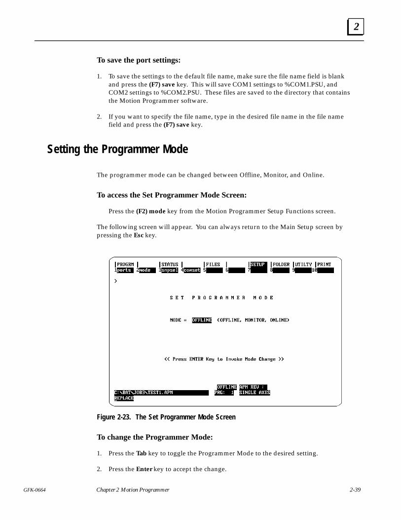
2
2-39GFK-0664 Chapter 2 Motion Programmer
To save the port settings:
1. To save the settings to the default file name, make sure the file name field is blankand press the (F7) save key. This will save COM1 settings to %COM1.PSU, andCOM2 settings to %COM2.PSU. These files are saved to the directory that containsthe Motion Programmer software.
2. If you want to specify the file name, type in the desired file name in the file namefield and press the (F7) save key.
Setting the Programmer Mode
The programmer mode can be changed between Offline, Monitor, and Online.
To access the Set Programmer Mode Screen:
Press the (F2) mode key from the Motion Programmer Setup Functions screen.
The following screen will appear. You can always return to the Main Setup screen bypressing the Esc key.
Figure 2-23. The Set Programmer Mode Screen
To change the Programmer Mode:
1. Press the Tab key to toggle the Programmer Mode to the desired setting.
2. Press the Enter key to accept the change.
2
2-40 Series 90 Axis Positioning Module (APM) Programmer’s Manual - August 1993 GFK-0664
Setting-Up APM Communications
To setup communications between the Motion Programmer and the APM, you will needto complete the following steps.
1. Connect the serial cable from the computer running the Motion Programmer soft-ware to the serial port on the APM.
Note
The connection between the programming computer and the APM30 istypically made from the RS-232 port of the computer through an RS-232to RS-485/RS-422 converter to the SNP Serial CommunicationsConnector on the APM. A Miniconverter Kit (IC690ACC901) whichincludes a converter and 6 ft cable is available for this purpose. This isthe same cable and converter that is used to connect to the SNP port onthe CPU of the PLC.
If you are making your own cable, refer to GFK-0707, The APM30 QuickReference and Installation Guide, for the pin-outs of the serialcommunications connector.
2. Go to the SNP Connections screen and select Direct or Multidrop communications.If you are using multidrop communications, you must select an SNP ID.
3. Go to the PLC Communications Serial Port Setup screen to set the communicationsparameters to match that of the APM Serial Communications port which is config-ured in the Logicmaster 90-30 configuration software.
4. Make sure the Motion Programmer is in the Online or Monitor mode by pressingAlt-M. Note that when communications are established, the Enabled/Disabled fieldand the SNPID field will appear.
The Select SNP Connections Screen
The Select SNP Connections screen is used in Multidrop applications. SNP is the propri-etary communications protocol used by the APM. From this screen you select the SNPID of the APM to which you want to communicate. You may also create a list of the SNPIDs you are using with a 6-character description for each.
The settings for these screens are saved to separate files. The procedures for using theshow port, show file, setup, and save functions are the same as for the printer setup de-scribed above.
To access the Select SNP Connections Screen:
Press the (F3) snpsel key from the Motion Programmer Setup Functions screen.
The following screen will appear. You can always return to the Main Setup screen bypressing the Esc key.
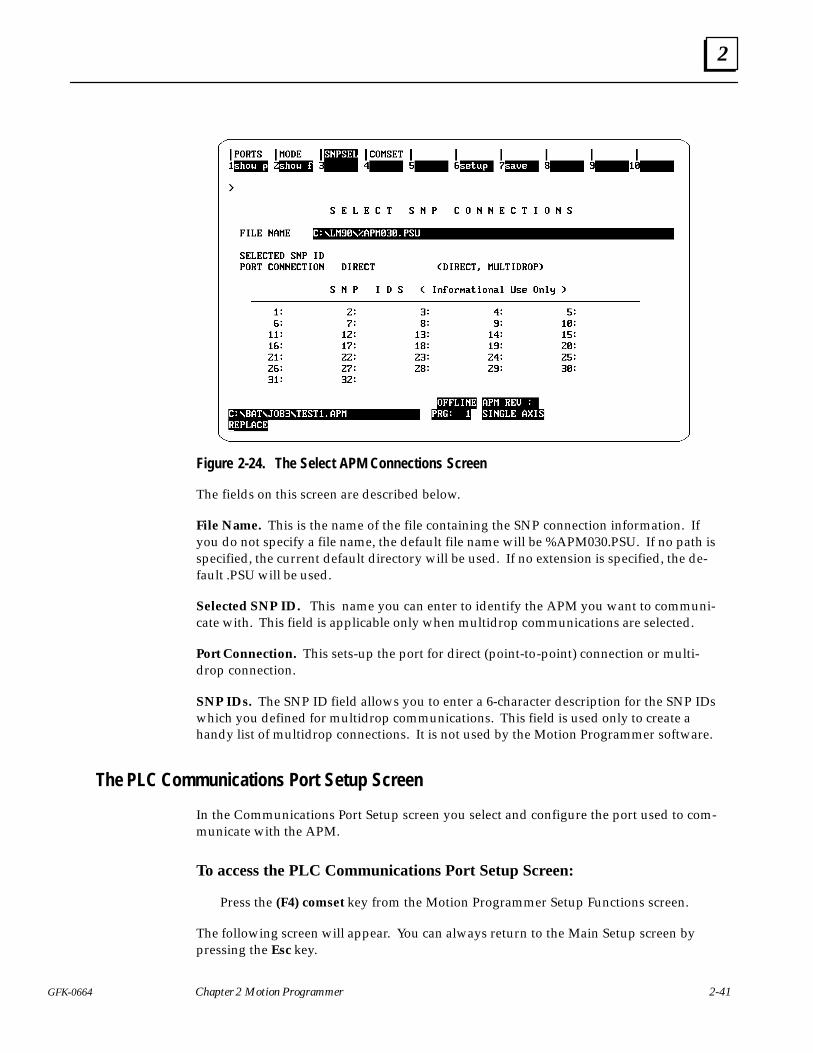
2
2-41GFK-0664 Chapter 2 Motion Programmer
Figure 2-24. The Select APM Connections Screen
The fields on this screen are described below.
File Name. This is the name of the file containing the SNP connection information. Ifyou do not specify a file name, the default file name will be %APM030.PSU. If no path isspecified, the current default directory will be used. If no extension is specified, the de-fault .PSU will be used.
Selected SNP ID. This name you can enter to identify the APM you want to communi-cate with. This field is applicable only when multidrop communications are selected.
Port Connection. This sets-up the port for direct (point-to-point) connection or multi-drop connection.
SNP IDs. The SNP ID field allows you to enter a 6-character description for the SNP IDswhich you defined for multidrop communications. This field is used only to create ahandy list of multidrop connections. It is not used by the Motion Programmer software.
The PLC Communications Port Setup Screen
In the Communications Port Setup screen you select and configure the port used to com-municate with the APM.
To access the PLC Communications Port Setup Screen:
Press the (F4) comset key from the Motion Programmer Setup Functions screen.
The following screen will appear. You can always return to the Main Setup screen bypressing the Esc key.
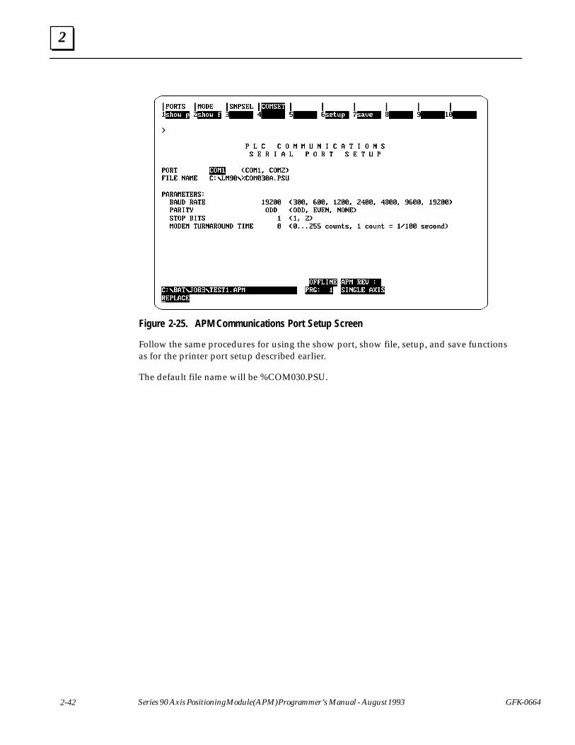
2
2-42 Series 90 Axis Positioning Module (APM) Programmer’s Manual - August 1993 GFK-0664
Figure 2-25. APM Communications Port Setup Screen
Follow the same procedures for using the show port, show file, setup, and save functionsas for the printer port setup described earlier.
The default file name will be %COM030.PSU.

2
2-43GFK-0664 Chapter 2 Motion Programmer
Section 6. Loading and Storing APM Files
This section describes the functions available in the Utilities Functions screen. Thesefunctions are similar to the utilities functions in the Logicmaster 90 Programmer. Topicscovered are:
� Loading from the APM to the Programmer
� Storing from the Programmer to the APM
� Verifying the APM with the Programmer
� Clearing APM memory.
� Read/Write/Verify EEPROM
To access the Utilities Functions screen:
Press the (F9) utilty key from the Main screen.
You can execute all the utilities functions from this screen.
Figure 2-26. Utilities Functions Screen
Loading from the APM to the Programmer
The load function is executed from the Load From APM to Programmer screen.
To access the Load From APM to Programmer Screen:
Press the (F1) load key from the Motion Programmer Utility Functions screen.
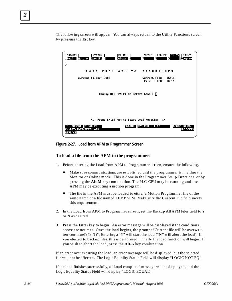
2
2-44 Series 90 Axis Positioning Module (APM) Programmer’s Manual - August 1993 GFK-0664
The following screen will appear. You can always return to the Utility Functions screenby pressing the Esc key.
Figure 2-27. Load from APM to Programmer Screen
To load a file from the APM to the programmer:
1. Before entering the Load from APM to Programmer screen, ensure the following.
� Make sure communications are established and the programmer is in either theMonitor or Online mode. This is done in the Programmer Setup Functions, or bypressing the Alt-M key combination. The PLC-CPU may be running and theAPM may be executing a motion program.
� The file in the APM must be loaded to either a Motion Programmer file of thesame name or a file named TEMP.APM. Make sure the Current File field meetsthis requirement.
2. In the Load from APM to Programmer screen, set the Backup All APM Files field to Yor N as desired.
3. Press the Enter key to begin. An error message will be displayed if the conditionsabove are not met. Once the load begins, the prompt “Current file will be overwrit-ten-continue? (Y/N)”. Entering a “Y” will start the load (“N” will abort the load). Ifyou elected to backup files, this is performed. Finally, the load function will begin. Ifyou wish to abort the load, press the Alt-A key combination.
If an error occurs during the load, an error message will be displayed, but the selectedfile will not be affected. The Logic Equality Status Field will display “LOGIC NOT EQ”.
If the load finishes successfully, a “Load complete” message will be displayed, and theLogic Equality Status Field will display “LOGIC EQUAL”.
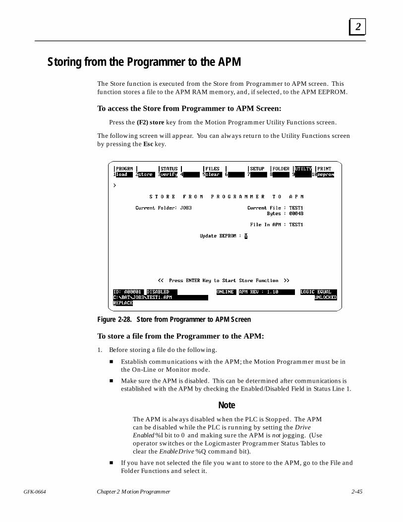
2
2-45GFK-0664 Chapter 2 Motion Programmer
Storing from the Programmer to the APM
The Store function is executed from the Store from Programmer to APM screen. Thisfunction stores a file to the APM RAM memory, and, if selected, to the APM EEPROM.
To access the Store from Programmer to APM Screen:
Press the (F2) store key from the Motion Programmer Utility Functions screen.
The following screen will appear. You can always return to the Utility Functions screenby pressing the Esc key.
Figure 2-28. Store from Programmer to APM Screen
To store a file from the Programmer to the APM:
1. Before storing a file do the following.
� Establish communications with the APM; the Motion Programmer must be inthe On-Line or Monitor mode.
� Make sure the APM is disabled. This can be determined after communications isestablished with the APM by checking the Enabled/Disabled Field in Status Line 1.
NoteThe APM is always disabled when the PLC is Stopped. The APMcan be disabled while the PLC is running by setting the DriveEnabled %I bit to 0 and making sure the APM is not jogging. (Useoperator switches or the Logicmaster Programmer Status Tables toclear the Enable Drive %Q command bit).
� If you have not selected the file you want to store to the APM, go to the File andFolder Functions and select it.
2
2-46 Series 90 Axis Positioning Module (APM) Programmer’s Manual - August 1993 GFK-0664
2. From the Store screen, select whether you want to update the APM EEPROM, Y or N.
3. Press the Enter key. If the file name you selected is the same as the file name in theAPM, the store will execute. If the file names do not match, the following messagewill be displayed, “File name in the APM does not match file to be stored; continue?(Y/N)” will be displayed. If the user answers “N” to the prompt, a message such as“Store aborted” will be displayed. However, if the user answers “Y”, then the storewill continue as if the names matched.
The store function will first check to see whether there is enough APM user RAM to holdall the programs and subroutines. If there is not enough user memory, an error messagewill appear. If there is enough APM user RAM, then a confirmation prompt to continuethe store will be displayed. If you reply N, the store will abort; if you reply Y, the storewill continue. After this point you may still abort the function by pressing the Alt-A keysequence.
Note
Release 1 APMs have 16 K bytes of program memory.
Release 2 APMs have 14 Kbytes of program memory; 2 Kbytes havebeen separated for other uses.
Any errors which occur after this point cause an error message to be displayed and theAPM to be cleared. The logic equality field is updated to “LOGIC NOT EQ”.
If the store finishes successfully, then the “Store complete” message will be displayed.The File in APM field will be updated to reflect the file just stored, and the logic equalityfield is updated to “LOGIC EQUAL”.
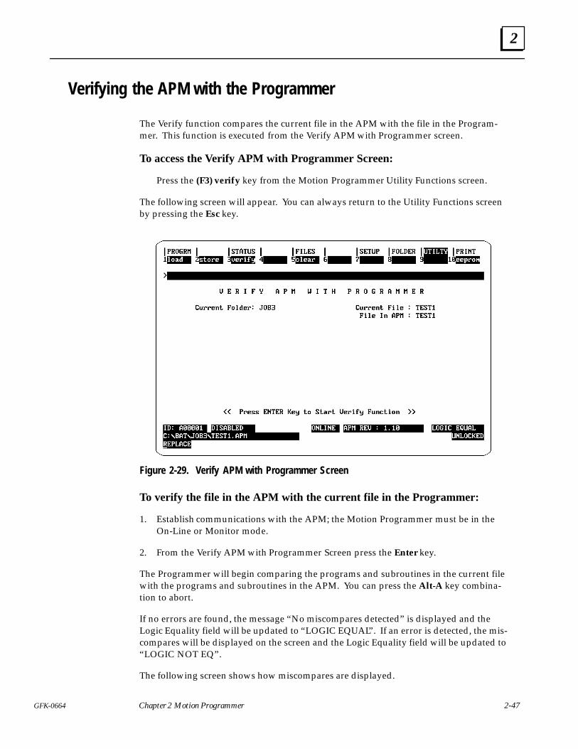
2
2-47GFK-0664 Chapter 2 Motion Programmer
Verifying the APM with the Programmer
The Verify function compares the current file in the APM with the file in the Program-mer. This function is executed from the Verify APM with Programmer screen.
To access the Verify APM with Programmer Screen:
Press the (F3) verify key from the Motion Programmer Utility Functions screen.
The following screen will appear. You can always return to the Utility Functions screenby pressing the Esc key.
Figure 2-29. Verify APM with Programmer Screen
To verify the file in the APM with the current file in the Programmer:
1. Establish communications with the APM; the Motion Programmer must be in theOn-Line or Monitor mode.
2. From the Verify APM with Programmer Screen press the Enter key.
The Programmer will begin comparing the programs and subroutines in the current filewith the programs and subroutines in the APM. You can press the Alt-A key combina-tion to abort.
If no errors are found, the message “No miscompares detected” is displayed and theLogic Equality field will be updated to “LOGIC EQUAL”. If an error is detected, the mis-compares will be displayed on the screen and the Logic Equality field will be updated to“LOGIC NOT EQ”.
The following screen shows how miscompares are displayed.
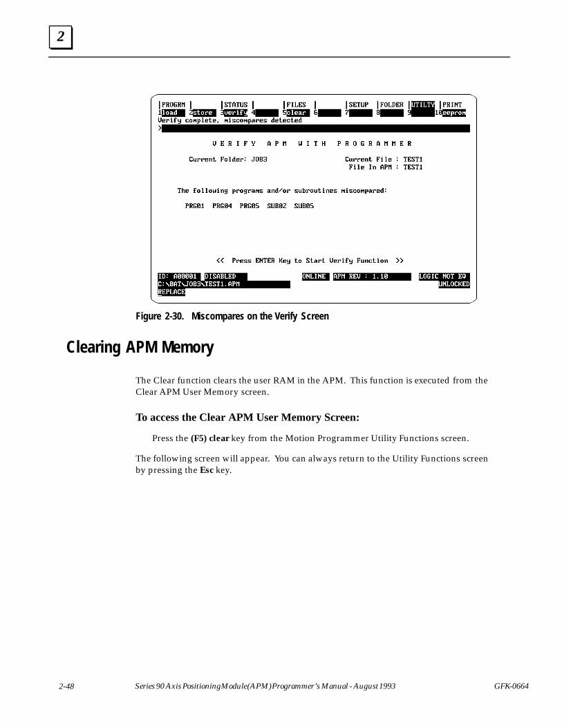
2
2-48 Series 90 Axis Positioning Module (APM) Programmer’s Manual - August 1993 GFK-0664
Figure 2-30. Miscompares on the Verify Screen
Clearing APM Memory
The Clear function clears the user RAM in the APM. This function is executed from theClear APM User Memory screen.
To access the Clear APM User Memory Screen:
Press the (F5) clear key from the Motion Programmer Utility Functions screen.
The following screen will appear. You can always return to the Utility Functions screenby pressing the Esc key.
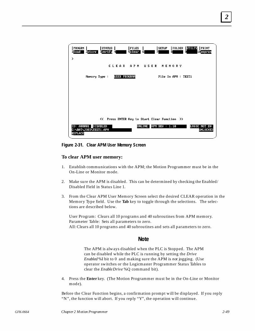
2
2-49GFK-0664 Chapter 2 Motion Programmer
Figure 2-31. Clear APM User Memory Screen
To clear APM user memory:
1. Establish communications with the APM; the Motion Programmer must be in theOn-Line or Monitor mode.
2. Make sure the APM is disabled. This can be determined by checking the Enabled/Disabled Field in Status Line 1.
3. From the Clear APM User Memory Screen select the desired CLEAR operation in theMemory Type field. Use the Tab key to toggle through the selections. The selec-tions are described below.
User Program: Clears all 10 programs and 40 subroutines from APM memory. Parameter Table: Sets all parameters to zero.All: Clears all 10 programs and 40 subroutines and sets all parameters to zero.
Note
The APM is always disabled when the PLC is Stopped. The APMcan be disabled while the PLC is running by setting the DriveEnabled %I bit to 0 and making sure the APM is not jogging. (Useoperator switches or the Logicmaster Programmer Status Tables toclear the Enable Drive %Q command bit).
4. Press the Enter key. (The Motion Programmer must be in the On-Line or Monitormode).
Before the Clear Function begins, a confirmation prompt will be displayed. If you reply“N”, the function will abort. If you reply “Y”, the operation will continue.
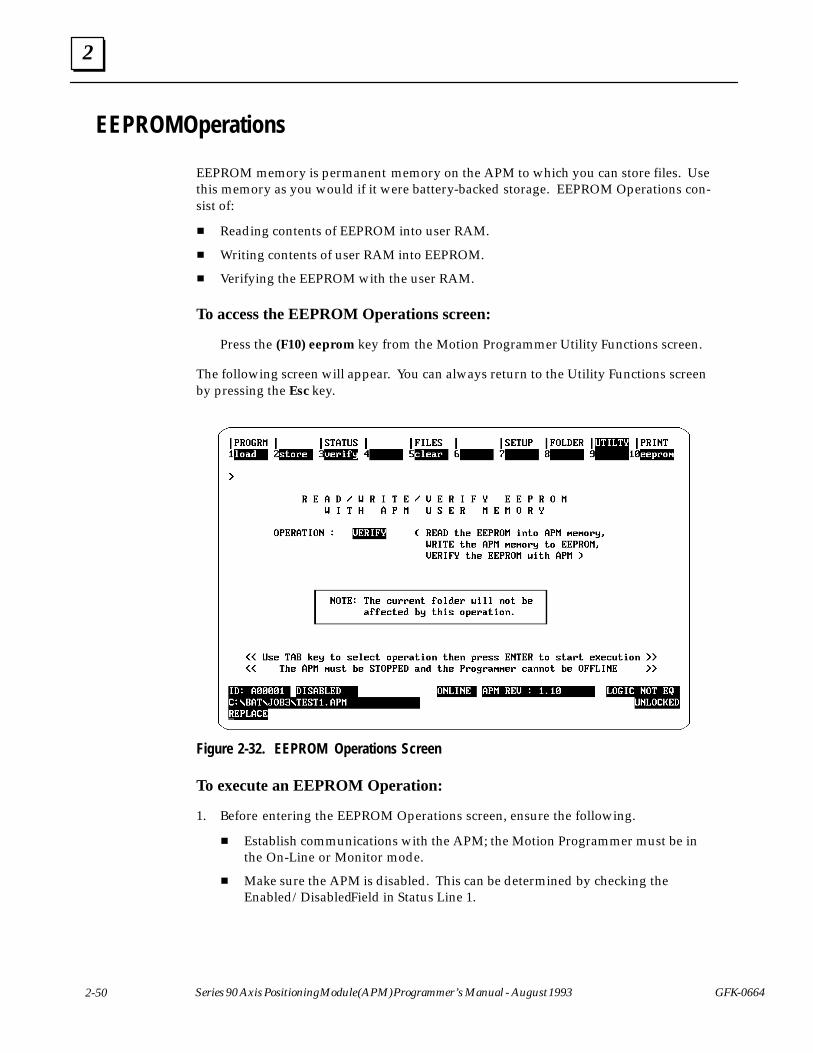
2
2-50 Series 90 Axis Positioning Module (APM) Programmer’s Manual - August 1993 GFK-0664
EEPROM Operations
EEPROM memory is permanent memory on the APM to which you can store files. Usethis memory as you would if it were battery-backed storage. EEPROM Operations con-sist of:
� Reading contents of EEPROM into user RAM.
� Writing contents of user RAM into EEPROM.
� Verifying the EEPROM with the user RAM.
To access the EEPROM Operations screen:
Press the (F10) eeprom key from the Motion Programmer Utility Functions screen.
The following screen will appear. You can always return to the Utility Functions screenby pressing the Esc key.
Figure 2-32. EEPROM Operations Screen
To execute an EEPROM Operation:
1. Before entering the EEPROM Operations screen, ensure the following.
� Establish communications with the APM; the Motion Programmer must be inthe On-Line or Monitor mode.
� Make sure the APM is disabled. This can be determined by checking theEnabled/Disabled Field in Status Line 1.
2
2-51GFK-0664 Chapter 2 Motion Programmer
Note
The APM is always disabled when the PLC is Stopped. The APM can bedisabled while the PLC is running by setting the Drive Enabled %I bit to 0and making sure the APM is not jogging. (Use operator switches or theLogicmaster Programmer Status Tables to clear the Enable Drive %Qcommand bit).
2. Select the desired EEPROM operation in the Operation field. Use the Tab key totoggle through the selections.
3. Press the Enter key.
Read EEPROM into APM User RAM. If the Operation field is set to READ, the APM Pro-grammer will initiate a request to copy all the data from the EEPROM into the APM RAMmemory.
Write APM User RAM into EEPROM. If the Operation field is set to WRITE, the APM Pro-grammer will initiate a request to copy all the data from the APM RAM memory not the EE-PROM.
Verify EEPROM with APM User RAM. If the Operation field is set to VERIFY, the APMProgrammer will initiate a request to compare all the data from the EEPROM with the APMRAM memory.
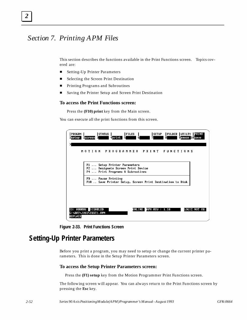
2
2-52 Series 90 Axis Positioning Module (APM) Programmer’s Manual - August 1993 GFK-0664
Section 7. Printing APM Files
This section describes the functions available in the Print Functions screen. Topics cov-ered are:
� Setting-Up Printer Parameters
� Selecting the Screen Print Destination
� Printing Programs and Subroutines
� Saving the Printer Setup and Screen Print Destination
To access the Print Functions screen:
Press the (F10) print key from the Main screen.
You can execute all the print functions from this screen.
Figure 2-33. Print Functions Screen
Setting-Up Printer Parameters
Before you print a program, you may need to setup or change the current printer pa-rameters. This is done in the Setup Printer Parameters screen.
To access the Setup Printer Parameters screen:
Press the (F1) setup key from the Motion Programmer Print Functions screen.
The following screen will appear. You can always return to the Print Functions screen bypressing the Esc key.
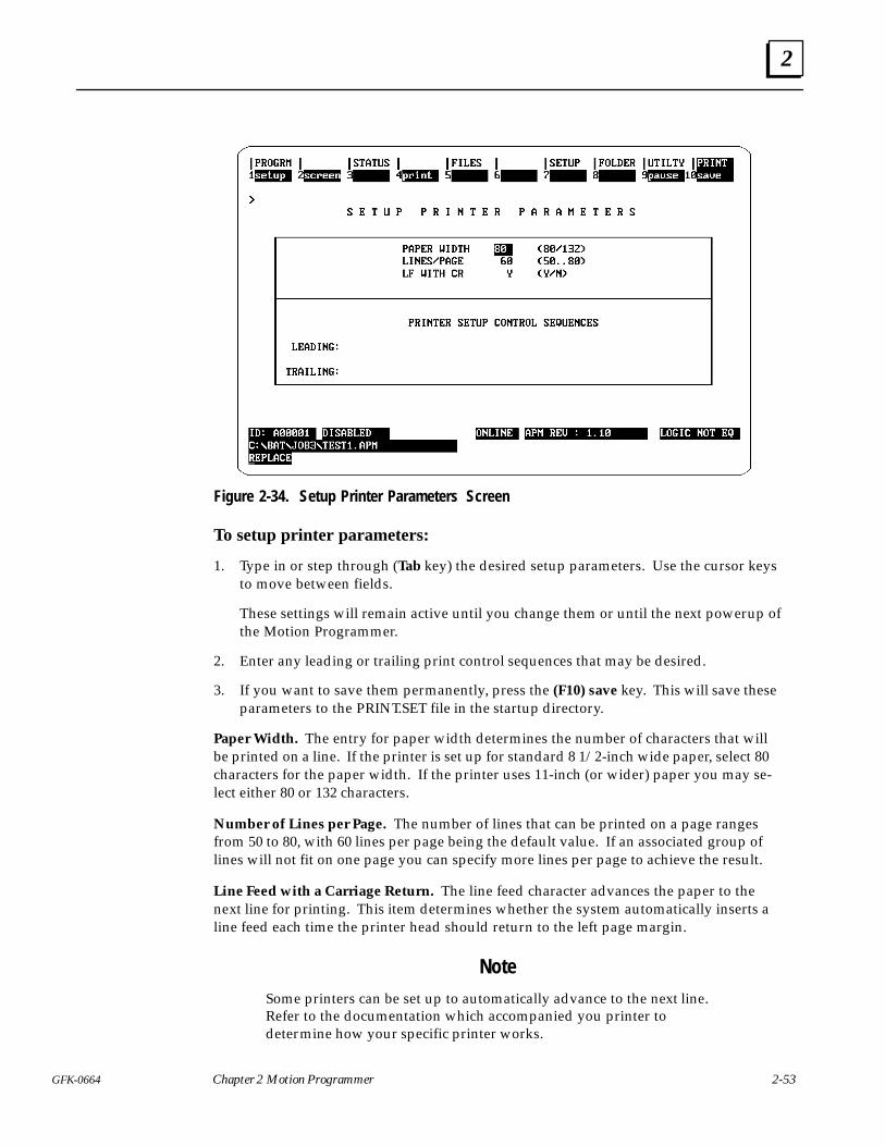
2
2-53GFK-0664 Chapter 2 Motion Programmer
Figure 2-34. Setup Printer Parameters Screen
To setup printer parameters:
1. Type in or step through (Tab key) the desired setup parameters. Use the cursor keysto move between fields.
These settings will remain active until you change them or until the next powerup ofthe Motion Programmer.
2. Enter any leading or trailing print control sequences that may be desired.
3. If you want to save them permanently, press the (F10) save key. This will save theseparameters to the PRINT.SET file in the startup directory.
Paper Width. The entry for paper width determines the number of characters that willbe printed on a line. If the printer is set up for standard 8 1/2-inch wide paper, select 80characters for the paper width. If the printer uses 11-inch (or wider) paper you may se-lect either 80 or 132 characters.
Number of Lines per Page. The number of lines that can be printed on a page rangesfrom 50 to 80, with 60 lines per page being the default value. If an associated group oflines will not fit on one page you can specify more lines per page to achieve the result.
Line Feed with a Carriage Return. The line feed character advances the paper to thenext line for printing. This item determines whether the system automatically inserts aline feed each time the printer head should return to the left page margin.
NoteSome printers can be set up to automatically advance to the next line.Refer to the documentation which accompanied you printer todetermine how your specific printer works.
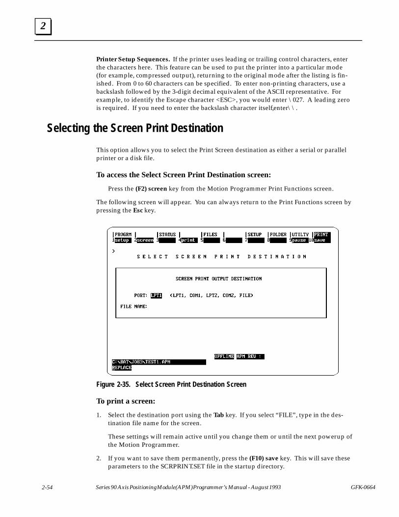
2
2-54 Series 90 Axis Positioning Module (APM) Programmer’s Manual - August 1993 GFK-0664
Printer Setup Sequences. If the printer uses leading or trailing control characters, enterthe characters here. This feature can be used to put the printer into a particular mode(for example, compressed output), returning to the original mode after the listing is fin-ished. From 0 to 60 characters can be specified. To enter non-printing characters, use abackslash followed by the 3-digit decimal equivalent of the ASCII representative. Forexample, to identify the Escape character <ESC>, you would enter \027. A leading zerois required. If you need to enter the backslash character itself, enter \\.
Selecting the Screen Print Destination
This option allows you to select the Print Screen destination as either a serial or parallelprinter or a disk file.
To access the Select Screen Print Destination screen:
Press the (F2) screen key from the Motion Programmer Print Functions screen.
The following screen will appear. You can always return to the Print Functions screen bypressing the Esc key.
Figure 2-35. Select Screen Print Destination Screen
To print a screen:
1. Select the destination port using the Tab key. If you select “FILE”, type in the des-tination file name for the screen.
These settings will remain active until you change them or until the next powerup ofthe Motion Programmer.
2. If you want to save them permanently, press the (F10) save key. This will save theseparameters to the SCRPRINT.SET file in the startup directory.

2
2-55GFK-0664 Chapter 2 Motion Programmer
3. Go to the Motion Programmer screen you want to print.
4. Print the screen by pressing Alt-P.
Printing Programs and Subroutines
This screen allows you to select the Programs and Subroutines to print.
To access the Print Motion Programs screen:
Press the (F4) print key from the Motion Programmer Print Functions screen.
The following screen will appear. You can always return to the Print Functions screen bypressing the Esc key.
Figure 2-36. Print Motion Program Screen
To print programs and subroutines:
1. Fill in the fields on the screen, see the description of the fields below.
2. Press the Enter key to begin the print operation.
Title. The title of the printout, which is printed at the top of every page.
Subtitle. The subtitle of the printout, which is printed underneath the title of everypage.
Header Page Option. You can set this to “no” if you do not want the header page to beprinted. Default = yes.

2
2-56 Series 90 Axis Positioning Module (APM) Programmer’s Manual - August 1993 GFK-0664
Starting Page Number. You can specify the starting page number for the print out.Default = 1.
Programs. This option allows you to specify whether to print all or none of the programs in anAPM file. Default = All.
Subroutines. This option allows you to specify whether to print all or none of the subroutinesin an APM file. Default = All.
Hex Command Prefix. This option allows you to specify whether to print the 6-byte com-mand (in hex) before its corresponding line in the program. If the line contains comments thatextend out to the 80 column length, and the printer is only set up for 80 columns, then the com-ment will be truncated on the printout (if necessary). This is done since the 6-byte hex com-mand needs to prefix the line being printed. Default = N.
Destination Port. This allows you to select the destination for the printout, a serial or parallelport or a disk file.
File Name. This field is used when you have specified FILE as the destination of the printout.If no path is specified (only the filename), then the print file will be put into the current folder.If a path is specified, the print file will be put in that path.
Pausing the Print Operation
You can pause the printout by pressing the (F9) pause key. To resume printing, press the(F9) pause key again.
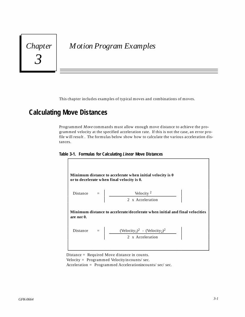
3 section level 1 1figure bi level 1 table_big level 1
3-1GFK-0664
Chapter 3 Motion Program Examples
This chapter includes examples of typical moves and combinations of moves.
Calculating Move Distances
Programmed Move commands must allow enough move distance to achieve the pro-grammed velocity at the specified acceleration rate. If this is not the case, an error pro-file will result . The formulas below show how to calculate the various acceleration dis-tances.
Table 3-1. Formulas for Calculating Linear Move DistancesÁÁÁÁÁÁÁÁÁÁÁÁÁÁÁÁÁÁÁÁÁÁÁÁÁÁÁÁÁÁÁÁÁÁÁÁÁÁÁÁÁÁÁÁÁÁÁÁÁÁÁÁÁÁÁÁÁÁÁÁÁÁÁÁÁÁÁÁÁÁÁÁÁÁÁÁÁÁÁÁÁÁÁÁÁÁÁÁÁÁÁÁÁÁÁÁÁÁÁÁÁÁÁÁÁÁÁÁÁÁÁÁÁÁÁÁÁÁÁÁÁÁÁÁÁÁÁÁÁÁÁÁÁÁÁÁÁÁ
Minimum distance to accelerate when initial velocity is 0 or to decelerate when final velocity is 0.
ÁÁÁÁÁÁÁÁÁÁDistance
ÁÁÁÁ=ÁÁÁÁÁÁÁÁÁÁÁÁÁÁÁÁÁÁÁÁÁÁÁÁÁÁÁÁ Velocity 2
ÁÁÁÁÁÁÁÁÁÁÁÁÁÁÁÁÁÁÁ
ÁÁÁÁÁÁÁÁÁÁÁÁÁÁÁÁÁÁÁÁÁÁÁÁÁÁÁÁÁÁÁÁÁÁÁÁÁ2 x Acceleration
ÁÁÁÁÁÁÁÁÁÁÁÁÁÁÁÁÁÁÁÁÁÁÁÁÁÁÁÁÁÁÁÁÁÁÁÁÁ
ÁÁÁÁÁÁÁÁÁÁÁÁÁÁÁÁÁÁÁÁÁÁÁÁÁÁÁÁÁÁÁÁÁÁÁÁÁÁÁÁÁÁÁÁÁÁÁÁÁÁÁÁÁÁÁÁÁÁÁÁÁÁÁÁÁÁÁÁÁÁÁÁÁÁÁÁÁÁÁÁÁÁÁÁÁÁÁÁÁÁÁÁ
Minimum distance to accelerate/decelerate when initial and final velocities are not 0.
ÁÁÁÁÁÁÁÁÁÁDistance
ÁÁÁÁ=ÁÁÁÁÁÁÁÁÁÁÁÁÁÁÁÁÁÁÁÁÁÁÁÁÁÁÁÁ(Velocity1)2 - (Velocity2)2
ÁÁÁÁÁÁÁÁÁÁÁÁÁÁÁÁÁÁÁ
ÁÁÁÁÁÁÁÁÁÁ
ÁÁÁÁÁÁ
ÁÁÁÁÁÁ
ÁÁÁÁÁÁÁÁÁÁÁÁÁÁÁÁÁÁÁÁÁÁÁÁÁÁÁÁÁÁÁÁÁÁÁÁ
2 x AccelerationÁÁÁÁÁÁ
ÁÁÁÁÁÁÁÁÁÁÁÁÁÁÁ
ÁÁÁÁÁÁÁÁÁÁÁÁÁÁÁ
ÁÁÁÁÁÁ
ÁÁÁÁÁÁ
ÁÁÁÁÁÁÁÁÁÁÁÁÁÁÁÁÁÁÁÁÁÁÁÁÁÁÁÁÁÁÁÁÁÁÁÁ
ÁÁÁÁÁÁ
ÁÁÁÁÁÁÁÁÁÁÁÁÁÁÁ
Distance = Required Move distance in counts.Velocity = Programmed Velocity in counts/sec.Acceleration = Programmed Acceleration in counts/sec/sec.
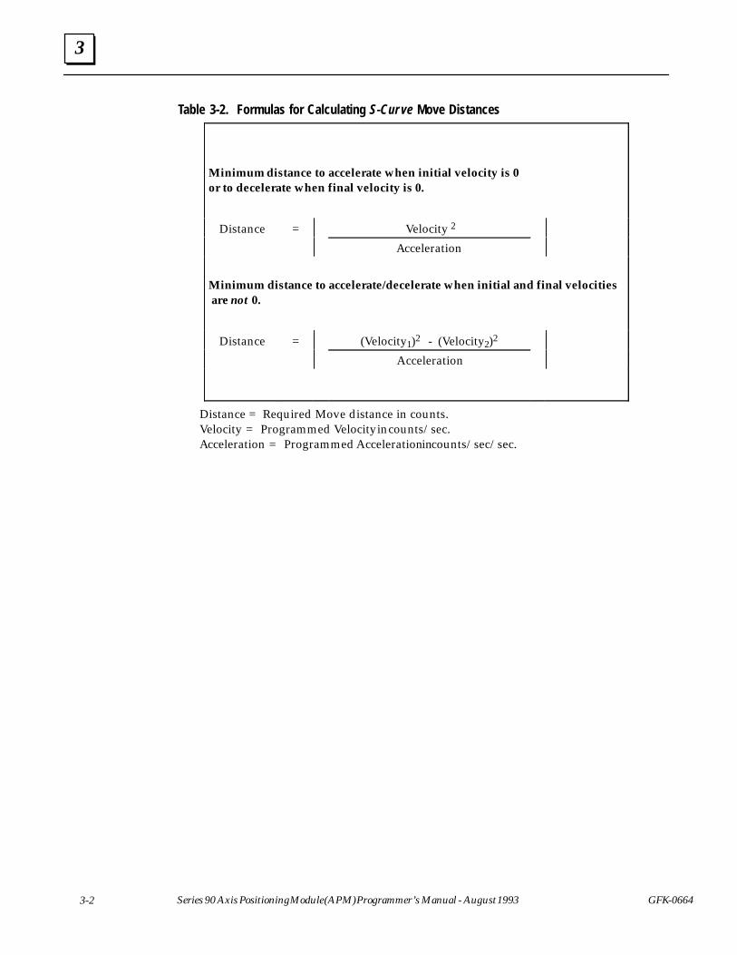
3
3-2 Series 90 Axis Positioning Module (APM) Programmer’s Manual - August 1993 GFK-0664
Table 3-2. Formulas for Calculating S-Cur ve Move DistancesÁÁÁÁÁÁÁÁÁÁÁÁÁÁÁÁÁÁÁÁÁÁÁÁÁÁÁÁÁÁÁÁÁÁÁÁÁÁÁÁÁÁÁÁÁÁÁÁÁÁÁÁÁÁÁÁÁÁÁÁÁÁÁÁÁÁÁÁÁÁÁÁÁÁÁÁÁÁÁÁÁÁÁÁÁÁÁÁÁÁÁÁÁÁÁÁÁÁÁÁÁÁÁÁÁÁÁÁÁÁÁÁÁÁÁÁÁÁÁÁÁÁÁÁÁÁÁÁÁÁÁÁÁÁÁÁÁÁ
Minimum distance to accelerate when initial velocity is 0 or to decelerate when final velocity is 0.
ÁÁÁÁÁÁÁÁÁÁDistance
ÁÁÁÁ=ÁÁÁÁÁÁÁÁÁÁÁÁÁÁÁÁÁÁÁÁÁÁÁÁÁÁÁÁ Velocity 2
ÁÁÁÁÁÁÁÁÁÁÁÁÁÁÁÁÁÁÁ
ÁÁÁÁÁÁÁÁÁÁÁÁÁÁÁÁÁÁÁÁÁÁÁÁÁÁÁÁÁÁÁÁÁÁÁÁÁAcceleration
ÁÁÁÁÁÁÁÁÁÁÁÁÁÁÁÁÁÁÁÁÁÁÁÁÁÁÁÁÁÁÁÁÁÁÁÁÁ
ÁÁÁÁÁÁÁÁÁÁÁÁÁÁÁÁÁÁÁÁÁÁÁÁÁÁÁÁÁÁÁÁÁÁÁÁÁÁÁÁÁÁÁÁÁÁÁÁÁÁÁÁÁÁÁÁÁÁÁÁÁÁÁÁÁÁÁÁÁÁÁÁÁÁÁÁÁÁÁÁÁÁÁÁÁÁÁÁÁÁÁÁ
Minimum distance to accelerate/decelerate when initial and final velocities are not 0.
ÁÁÁÁÁÁÁÁÁÁDistance
ÁÁÁÁ=ÁÁÁÁÁÁÁÁÁÁÁÁÁÁÁÁÁÁÁÁÁÁÁÁÁÁÁÁ(Velocity1)2 - (Velocity2)2
ÁÁÁÁÁÁÁÁÁÁÁÁÁÁÁÁÁÁÁ
ÁÁÁÁÁÁÁÁÁÁÁÁÁÁÁÁÁÁÁÁÁÁÁÁÁÁÁÁÁÁÁÁÁÁÁÁÁ Acceleration
ÁÁÁÁÁÁÁÁÁÁÁÁÁÁÁÁÁÁÁ
ÁÁÁÁÁÁÁÁÁÁ
ÁÁÁÁÁÁ
ÁÁÁÁÁÁ
ÁÁÁÁÁÁÁÁÁÁÁÁÁÁÁÁÁÁÁÁÁÁÁÁÁÁÁÁÁÁÁÁÁÁÁÁ
ÁÁÁÁÁÁ
ÁÁÁÁÁÁÁÁÁÁÁÁÁÁÁ
Distance = Required Move distance in counts.Velocity = Programmed Velocity in counts/sec.Acceleration = Programmed Acceleration in counts/sec/sec.
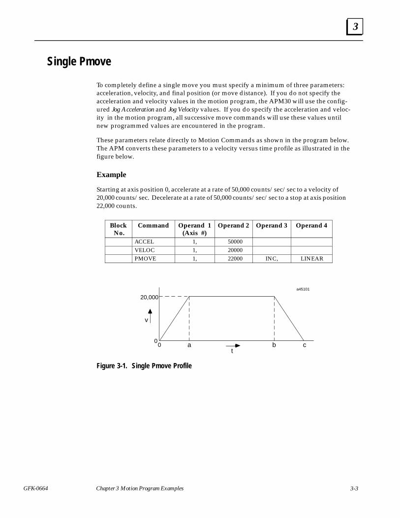
3
3-3GFK-0664 Chapter 3 Motion Program Examples
Single Pmove
To completely define a single move you must specify a minimum of three parameters:acceleration, velocity, and final position (or move distance). If you do not specify theacceleration and velocity values in the motion program, the APM30 will use the config-ured Jog Acceleration and Jog Velocity values. If you do specify the acceleration and veloc-ity in the motion program, all successive move commands will use these values untilnew programmed values are encountered in the program.
These parameters relate directly to Motion Commands as shown in the program below.The APM converts these parameters to a velocity versus time profile as illustrated in thefigure below.
Example
Starting at axis position 0, accelerate at a rate of 50,000 counts/sec/sec to a velocity of20,000 counts/sec. Decelerate at a rate of 50,000 counts/sec/sec to a stop at axis position22,000 counts.
ÁÁÁÁÁÁÁÁÁÁÁÁ
Block No.
ÁÁÁÁÁÁÁÁÁÁÁÁÁÁÁ
CommandÁÁÁÁÁÁÁÁÁÁÁÁÁÁÁ
Operand 1(Axis #)
ÁÁÁÁÁÁÁÁÁÁÁÁÁÁÁ
Operand 2ÁÁÁÁÁÁÁÁÁÁÁÁ
Operand 3ÁÁÁÁÁÁÁÁÁÁÁÁÁÁÁÁÁÁ
Operand 4
ÁÁÁÁÁÁÁÁ
ÁÁÁÁÁÁÁÁÁÁ
ACCEL ÁÁÁÁÁÁÁÁÁÁ
1, ÁÁÁÁÁÁÁÁÁÁ
50000 ÁÁÁÁÁÁÁÁ
ÁÁÁÁÁÁÁÁÁÁÁÁÁÁÁÁ
ÁÁÁÁÁÁÁÁÁÁÁÁÁÁ
VELOC ÁÁÁÁÁÁÁÁÁÁ
1, ÁÁÁÁÁÁÁÁÁÁ
20000 ÁÁÁÁÁÁÁÁ
ÁÁÁÁÁÁÁÁÁÁÁÁÁÁÁÁ
ÁÁÁÁÁÁÁÁÁÁÁÁÁÁ
PMOVE ÁÁÁÁÁÁÁÁÁÁ
1, ÁÁÁÁÁÁÁÁÁÁ
22000 ÁÁÁÁÁÁÁÁ
INC, ÁÁÁÁÁÁÁÁÁÁÁÁ
LINEAR
20,000
a45101
00 a b c
t
v
Figure 3-1. Single Pmove Profile
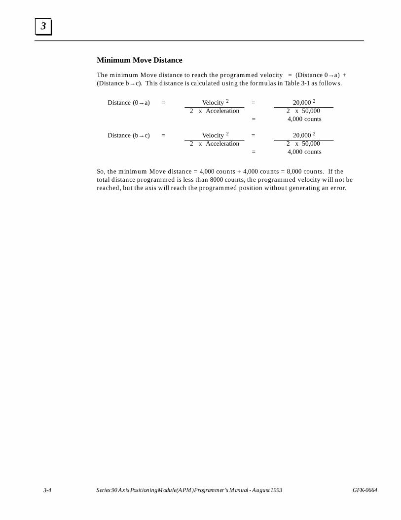
3
3-4 Series 90 Axis Positioning Module (APM) Programmer’s Manual - August 1993 GFK-0664
Minimum Move Distance
The minimum Move distance to reach the programmed velocity = (Distance 0→a) +(Distance b→c). This distance is calculated using the formulas in Table 3-1 as follows.
ÁÁÁÁÁÁÁÁÁÁÁÁ
Distance (0→a)ÁÁÁÁÁÁ
=ÁÁÁÁÁÁÁÁÁÁÁÁÁÁÁÁÁÁ
Velocity 2ÁÁÁÁÁÁ
=ÁÁÁÁÁÁÁÁÁÁÁÁÁÁÁÁÁÁ
20,000 2ÁÁÁÁÁÁÁÁÁÁÁÁ
ÁÁÁÁÁÁ
ÁÁÁÁÁÁÁÁÁÁÁÁÁÁÁÁÁÁ
2 x AccelerationÁÁÁÁÁÁÁÁÁÁÁÁÁÁÁÁÁÁÁÁÁÁÁÁ
2 x 50,000ÁÁÁÁ
=ÁÁÁÁÁÁÁÁÁÁÁÁÁÁÁÁÁÁÁÁ
4,000 counts
ÁÁÁÁÁÁDistance (b→c)ÁÁÁ= ÁÁÁÁÁÁÁÁÁ Velocity 2 ÁÁÁ= ÁÁÁÁÁÁÁÁÁ 20,000 2ÁÁÁÁÁÁÁÁÁÁÁÁ
ÁÁÁÁÁÁ
ÁÁÁÁÁÁÁÁÁÁÁÁÁÁÁÁÁÁ
2 x AccelerationÁÁÁÁÁÁÁÁÁÁÁÁÁÁÁÁÁÁÁÁÁÁÁÁ
2 x 50,000ÁÁÁÁ
=ÁÁÁÁÁÁÁÁÁÁÁÁÁÁÁÁÁÁÁÁ
4,000 counts
So, the minimum Move distance = 4,000 counts + 4,000 counts = 8,000 counts. If thetotal distance programmed is less than 8000 counts, the programmed velocity will not bereached, but the axis will reach the programmed position without generating an error.
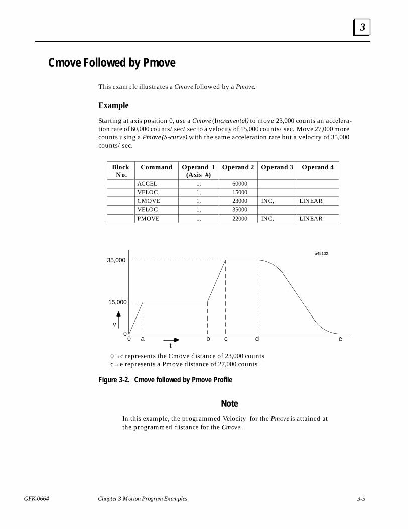
3
3-5GFK-0664 Chapter 3 Motion Program Examples
Cmove Followed by Pmove
This example illustrates a Cmove followed by a Pmove.
Example
Starting at axis position 0, use a Cmove (Incremental) to move 23,000 counts an accelera-tion rate of 60,000 counts/sec/sec to a velocity of 15,000 counts/sec. Move 27,000 morecounts using a Pmove (S-curve) with the same acceleration rate but a velocity of 35,000counts/sec.
ÁÁÁÁÁÁÁÁÁÁÁÁ
Block No.
ÁÁÁÁÁÁÁÁÁÁÁÁÁÁÁ
CommandÁÁÁÁÁÁÁÁÁÁÁÁÁÁÁ
Operand 1(Axis #)
ÁÁÁÁÁÁÁÁÁÁÁÁÁÁÁ
Operand 2ÁÁÁÁÁÁÁÁÁÁÁÁ
Operand 3ÁÁÁÁÁÁÁÁÁÁÁÁÁÁÁÁÁÁ
Operand 4
ÁÁÁÁÁÁÁÁ
ÁÁÁÁÁÁÁÁÁÁ
ACCEL ÁÁÁÁÁÁÁÁÁÁ
1, ÁÁÁÁÁÁÁÁÁÁ
60000 ÁÁÁÁÁÁÁÁ
ÁÁÁÁÁÁÁÁÁÁÁÁÁÁÁÁ
ÁÁÁÁÁÁÁÁÁÁÁÁÁÁ
VELOC ÁÁÁÁÁÁÁÁÁÁ
1, ÁÁÁÁÁÁÁÁÁÁ
15000 ÁÁÁÁÁÁÁÁ
ÁÁÁÁÁÁÁÁÁÁÁÁÁÁÁÁ
ÁÁÁÁÁÁÁÁÁÁÁÁÁÁ
CMOVE ÁÁÁÁÁÁÁÁÁÁ
1, ÁÁÁÁÁÁÁÁÁÁ
23000 ÁÁÁÁÁÁÁÁ
INC, ÁÁÁÁÁÁÁÁÁÁÁÁ
LINEARÁÁÁÁÁÁÁÁ
ÁÁÁÁÁÁÁÁÁÁVELOC
ÁÁÁÁÁÁÁÁÁÁ1,
ÁÁÁÁÁÁÁÁÁÁ35000
ÁÁÁÁÁÁÁÁ
ÁÁÁÁÁÁÁÁÁÁÁÁÁÁÁÁ
ÁÁÁÁÁÁÁÁÁÁÁÁÁÁ
PMOVEÁÁÁÁÁÁÁÁÁÁ
1,ÁÁÁÁÁÁÁÁÁÁ
22000ÁÁÁÁÁÁÁÁ
INC,ÁÁÁÁÁÁÁÁÁÁÁÁ
LINEAR
ÎÎÎÎÎÎÎÎÎÎÎÎÎÎÎÎ
ÎÎÎÎ
a45102
00 b c d
t
v
15,000ÎÎÎÎÎÎÎÎÎÎÎÎ
ea
35,000
ÎÎÎÎ
ÎÎÎÎÎÎÎÎÎ
0→c represents the Cmove distance of 23,000 countsc→e represents a Pmove distance of 27,000 counts
Figure 3-2. Cmove followed by Pmove Profile
Note
In this example, the programmed Velocity for the Pmove is attained atthe programmed distance for the Cmove.
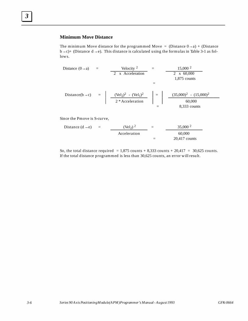
3
3-6 Series 90 Axis Positioning Module (APM) Programmer’s Manual - August 1993 GFK-0664
Minimum Move Distance
The minimum Move distance for the programmed Move = (Distance 0→a) + (Distanceb→c)+ (Distance d→e). This distance is calculated using the formulas in Table 3-1 as fol-lows.
ÁÁÁÁÁÁÁÁÁÁÁÁÁÁ
Distance (0→a) ÁÁÁÁ
=ÁÁÁÁÁÁÁÁÁÁÁÁÁÁÁÁÁÁ
Velocity 2 ÁÁÁÁÁÁ
=ÁÁÁÁÁÁÁÁÁÁÁÁÁÁÁÁÁÁ
15,000 2
ÁÁÁÁÁÁÁÁÁÁÁÁÁÁ
ÁÁÁÁÁÁÁÁÁÁÁÁÁÁÁÁÁÁÁÁÁÁ
2 x AccelerationÁÁÁÁÁÁ
ÁÁÁÁÁÁÁÁÁÁÁÁÁÁÁÁÁÁ
2 x 60,000
ÁÁÁÁÁÁÁÁÁÁÁÁÁÁÁÁÁÁÁÁÁÁÁÁÁÁÁÁÁÁÁÁÁÁ
=ÁÁÁÁÁÁÁÁÁÁÁÁÁÁÁÁÁÁ
1,875 counts
ÁÁÁÁÁÁÁÁÁÁÁÁÁÁ
Distance(b→c)ÁÁÁÁ
=ÁÁÁÁÁÁÁÁÁÁÁÁÁÁÁÁÁÁ
(Vel2)2 - (Vel1)2ÁÁÁÁÁÁÁÁÁÁ
=ÁÁÁÁÁÁÁÁÁÁÁÁÁÁÁÁÁÁÁÁ
(35,000)2 - (15,000)2 ÁÁÁÁÁÁÁÁÁÁÁ
ÁÁÁÁÁÁÁÁÁÁÁÁÁÁÁÁÁÁÁÁÁÁÁÁÁÁÁÁÁ
2 * AccelerationÁÁÁÁÁÁÁÁÁÁÁÁÁÁÁÁÁÁÁÁÁÁÁÁÁÁÁÁÁÁ
60,000ÁÁÁÁÁÁÁÁÁÁÁÁÁÁÁÁÁÁÁÁÁÁ
ÁÁÁÁÁÁÁÁÁÁÁÁÁÁÁÁÁÁ = ÁÁÁÁÁÁÁÁÁÁÁÁÁÁÁÁÁÁ
8,333 counts
Since the Pmove is S-curve,ÁÁÁÁÁÁÁÁÁÁÁÁÁÁDistance (d→e)
ÁÁÁÁ=ÁÁÁÁÁÁÁÁÁÁÁÁÁÁÁÁÁÁ (Vel2) 2
ÁÁÁÁÁÁ=
ÁÁÁÁÁÁÁÁÁÁÁÁÁÁÁÁÁÁ 35,000 2ÁÁÁÁÁÁÁ
ÁÁÁÁÁÁÁÁÁÁÁÁÁÁÁÁÁÁÁÁÁÁÁÁÁÁÁÁÁAcceleration
ÁÁÁÁÁÁ
ÁÁÁÁÁÁÁÁÁÁÁÁÁÁÁÁÁÁ60,000ÁÁÁÁÁÁÁÁÁÁÁÁÁÁÁÁ
ÁÁÁÁÁÁÁÁÁÁÁÁÁÁÁÁ =ÁÁÁÁÁÁÁÁÁÁÁÁÁÁÁÁÁÁ
20,417 counts
So, the total distance required = 1,875 counts + 8,333 counts + 20,417 = 30,625 counts.If the total distance programmed is less than 30,625 counts, an error will result.
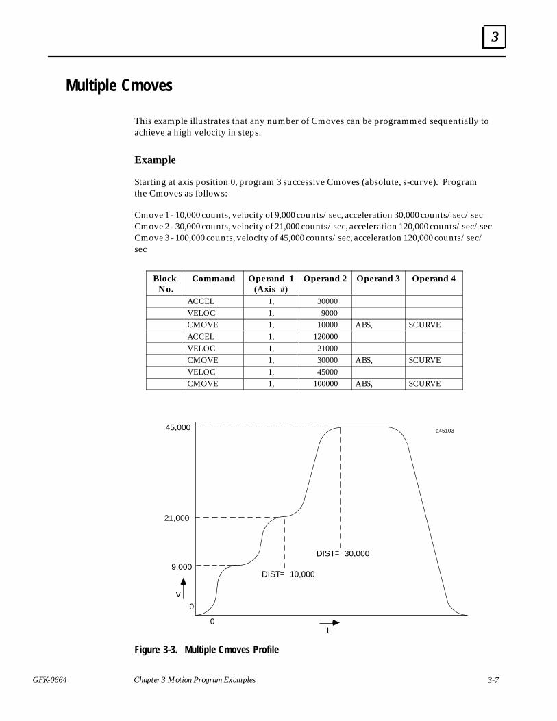
3
3-7GFK-0664 Chapter 3 Motion Program Examples
Multiple Cmoves
This example illustrates that any number of Cmoves can be programmed sequentially toachieve a high velocity in steps.
Example
Starting at axis position 0, program 3 successive Cmoves (absolute, s-curve). Programthe Cmoves as follows:
Cmove 1 - 10,000 counts, velocity of 9,000 counts/sec, acceleration 30,000 counts/sec/secCmove 2 - 30,000 counts, velocity of 21,000 counts/sec, acceleration 120,000 counts/sec/secCmove 3 - 100,000 counts, velocity of 45,000 counts/sec, acceleration 120,000 counts/sec/sec
ÁÁÁÁÁÁÁÁÁÁÁÁ
Block No.ÁÁÁÁÁÁÁÁÁÁÁÁÁÁÁ
CommandÁÁÁÁÁÁÁÁÁÁÁÁÁÁÁ
Operand 1(Axis #)
ÁÁÁÁÁÁÁÁÁÁÁÁÁÁÁ
Operand 2ÁÁÁÁÁÁÁÁÁÁÁÁ
Operand 3ÁÁÁÁÁÁÁÁÁÁÁÁÁÁÁÁÁÁ
Operand 4
ÁÁÁÁÁÁÁÁÁACCEL ÁÁÁÁÁ1, ÁÁÁÁÁ30000 ÁÁÁÁÁÁÁÁÁÁÁÁÁÁÁÁÁÁ
ÁÁÁÁÁÁÁÁÁÁVELOC
ÁÁÁÁÁÁÁÁÁÁ1,
ÁÁÁÁÁÁÁÁÁÁ9000
ÁÁÁÁÁÁÁÁ
ÁÁÁÁÁÁÁÁÁÁÁÁÁÁÁÁ
ÁÁÁÁÁÁÁÁÁÁÁÁÁÁ
CMOVEÁÁÁÁÁÁÁÁÁÁ
1,ÁÁÁÁÁÁÁÁÁÁ
10000ÁÁÁÁÁÁÁÁ
ABS,ÁÁÁÁÁÁÁÁÁÁÁÁ
SCURVEÁÁÁÁÁÁÁÁ
ÁÁÁÁÁÁÁÁÁÁ
ACCEL ÁÁÁÁÁÁÁÁÁÁ
1, ÁÁÁÁÁÁÁÁÁÁ
120000 ÁÁÁÁÁÁÁÁ
ÁÁÁÁÁÁÁÁÁÁÁÁÁÁÁÁ
ÁÁÁÁÁÁÁÁÁÁÁÁÁÁ
VELOC ÁÁÁÁÁÁÁÁÁÁ
1, ÁÁÁÁÁÁÁÁÁÁ
21000 ÁÁÁÁÁÁÁÁ
ÁÁÁÁÁÁÁÁÁÁÁÁÁÁÁÁ
ÁÁÁÁÁÁÁÁÁÁÁÁÁÁ
CMOVE ÁÁÁÁÁÁÁÁÁÁ
1, ÁÁÁÁÁÁÁÁÁÁ
30000 ÁÁÁÁÁÁÁÁ
ABS, ÁÁÁÁÁÁÁÁÁÁÁÁ
SCURVE
ÁÁÁÁÁÁÁÁ
ÁÁÁÁÁÁÁÁÁÁ
VELOC ÁÁÁÁÁÁÁÁÁÁ
1, ÁÁÁÁÁÁÁÁÁÁ
45000 ÁÁÁÁÁÁÁÁ
ÁÁÁÁÁÁÁÁÁÁÁÁ
ÁÁÁÁÁÁÁÁ
ÁÁÁÁÁÁÁÁÁÁCMOVE
ÁÁÁÁÁÁÁÁÁÁ1,
ÁÁÁÁÁÁÁÁÁÁ100000
ÁÁÁÁÁÁÁÁABS,
ÁÁÁÁÁÁÁÁÁÁÁÁSCURVE
ÎÎ
10,000
a45103
ÎÎ
DIST
ÎÎÎÎÎÎ
DIST 30,000
ÎÎÎÎÎÎ
9,000
v
45,000
0
ÎÎÎÎ
ÎÎ
ÎÎ
ÎÎÎ
0
ÎÎÎÎ
t
21,000
ÎÎÎÎÎÎ
ÎÎÎÎ
Figure 3-3. Multiple Cmoves Profile
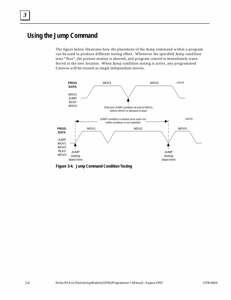
3
3-8 Series 90 Axis Positioning Module (APM) Programmer’s Manual - August 1993 GFK-0664
Using the Jump Command
The figure below illustrates how the placement of the Jump command within a programcan be used to produce different testing effect. Whenever the specified Jump conditiontests “True”, the present motion is aborted, and program control is immediately trans-ferred to the new location. When Jump condition testing is active, any programmedCmoves will be treated as single independent moves.
MOV1 MOV2
Only test JUMP condition at end of MOV1,before MOV2 is allowed to start.
PROGDATA
MOV1JUMPBLK#MOV2
a45104
ÎÎÎÎÎÎ
ÎÎÎÎÎÎÎÎÎÎÎÎ
ÎÎÎ
MOV1 MOV2
JUMPtesting
starts here
PROGDATA
JUMPMOV1MOV2BLK#MOV3
a45105
JUMPtesting
stops here
MOV3
JUMP condition is tested once each mswhile condition is not satisfied
Figure 3-4. Jump Command Condition Testing

A
A-1GFK-0664
Appendix A APM Motion Commands
This appendix describes each APM Motion Program command in detail. Both the MotionProgrammer format and the Program Zero Editor format are presented for the commandswhen applicable.
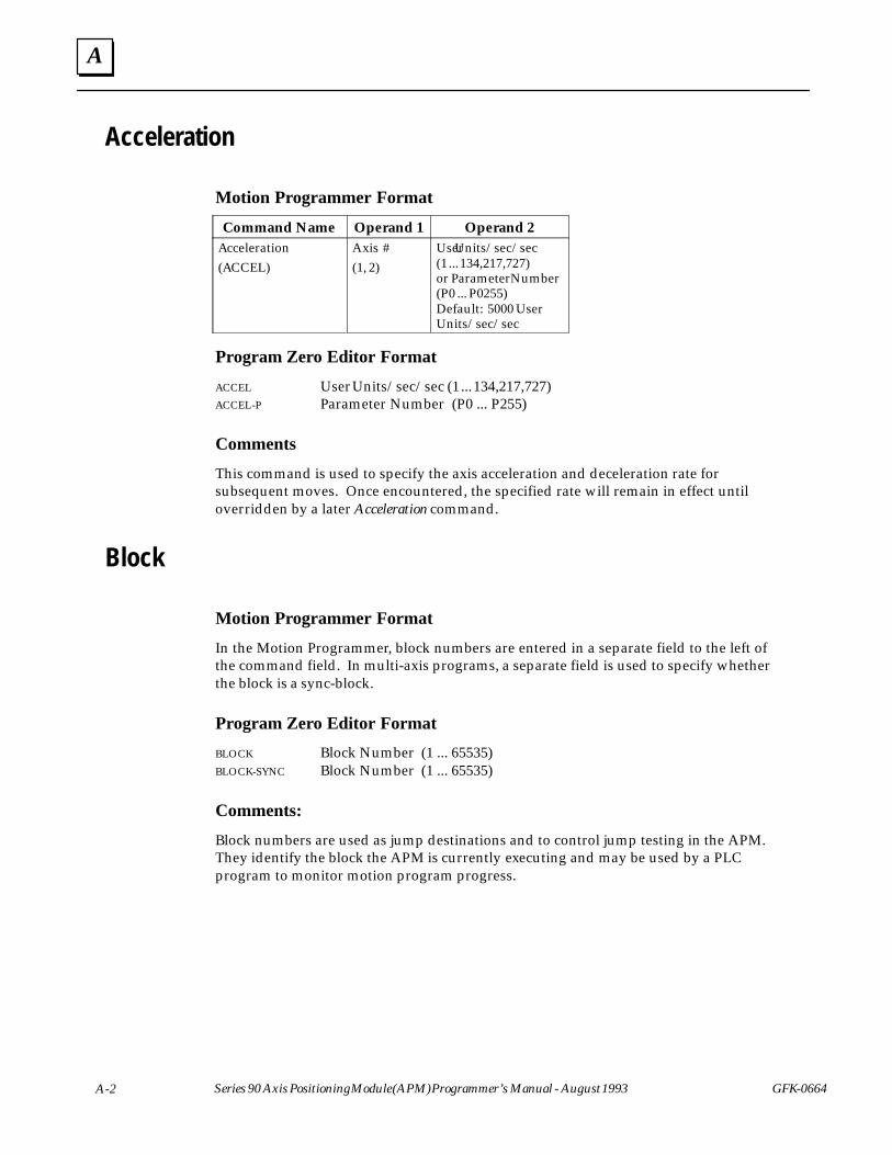
A
A-2 Series 90 Axis Positioning Module (APM) Programmer’s Manual - August 1993 GFK-0664
Acceleration
Motion Programmer FormatÁÁÁÁÁÁÁÁÁÁÁÁÁÁ
Command NameÁÁÁÁÁÁÁÁÁÁ
Operand 1ÁÁÁÁÁÁÁÁÁÁÁÁÁÁ
Operand 2ÁÁÁÁÁÁÁÁÁÁÁÁÁÁÁÁÁÁÁÁÁÁÁÁÁÁÁÁÁÁÁÁÁÁÁ
Acceleration(ACCEL)
ÁÁÁÁÁÁÁÁÁÁÁÁÁÁÁÁÁÁÁÁÁÁÁÁÁ
Axis #(1, 2)
ÁÁÁÁÁÁÁÁÁÁÁÁÁÁÁÁÁÁÁÁÁÁÁÁÁÁÁÁÁÁÁÁÁÁÁ
User Units/sec/sec(1 ... 134,217,727)or Parameter Number(P0 ... P0255)Default: 5000 UserUnits/sec/sec
Program Zero Editor Format
ACCEL User Units/sec/sec (1 ... 134,217,727)ACCEL-P Parameter Number (P0 ... P255)
Comments
This command is used to specify the axis acceleration and deceleration rate forsubsequent moves. Once encountered, the specified rate will remain in effect untiloverridden by a later Acceleration command.
Block
Motion Programmer Format
In the Motion Programmer, block numbers are entered in a separate field to the left ofthe command field. In multi-axis programs, a separate field is used to specify whetherthe block is a sync-block.
Program Zero Editor Format
BLOCK Block Number (1 ... 65535)BLOCK-SYNC Block Number (1 ... 65535)
Comments:
Block numbers are used as jump destinations and to control jump testing in the APM.They identify the block the APM is currently executing and may be used by a PLCprogram to monitor motion program progress.
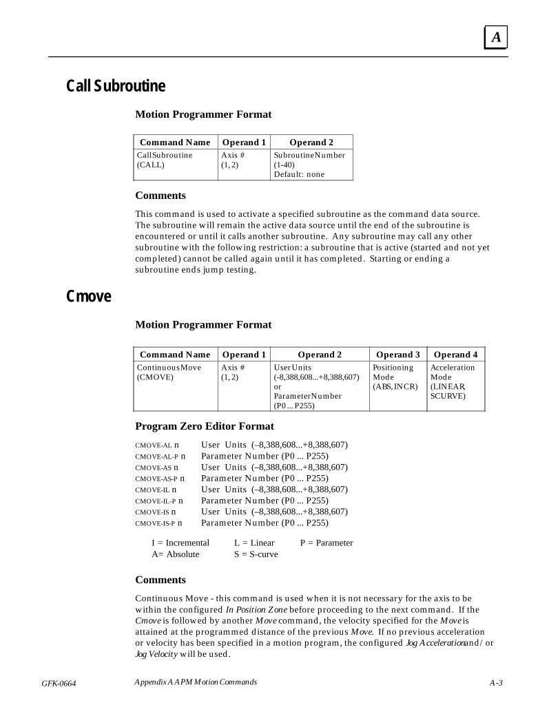
A
GFK-0664 A-3Appendix A APM Motion Commands
Call Subroutine
Motion Programmer Format
ÁÁÁÁÁÁÁÁÁÁÁÁÁÁ
Command NameÁÁÁÁÁÁÁÁÁÁ
Operand 1ÁÁÁÁÁÁÁÁÁÁÁÁÁÁ
Operand 2ÁÁÁÁÁÁÁÁÁÁÁÁÁÁÁÁÁÁÁÁÁ
Call Subroutine(CALL)
ÁÁÁÁÁÁÁÁÁÁÁÁÁÁÁ
Axis #(1, 2)
ÁÁÁÁÁÁÁÁÁÁÁÁÁÁÁÁÁÁÁÁÁ
Subroutine Number(1-40)Default: none
Comments
This command is used to activate a specified subroutine as the command data source.The subroutine will remain the active data source until the end of the subroutine isencountered or until it calls another subroutine. Any subroutine may call any othersubroutine with the following restriction: a subroutine that is active (started and not yetcompleted) cannot be called again until it has completed. Starting or ending asubroutine ends jump testing.
Cmove
Motion Programmer Format
ÁÁÁÁÁÁÁÁÁÁÁÁÁÁ
Command NameÁÁÁÁÁÁÁÁÁÁ
Operand 1ÁÁÁÁÁÁÁÁÁÁÁÁÁÁÁÁ
Operand 2ÁÁÁÁÁÁÁÁÁÁ
Operand 3ÁÁÁÁÁÁÁÁÁÁ
Operand 4ÁÁÁÁÁÁÁÁÁÁÁÁÁÁÁÁÁÁÁÁÁÁÁÁÁÁÁÁÁÁÁÁÁÁÁ
Continuous Move(CMOVE)
ÁÁÁÁÁÁÁÁÁÁÁÁÁÁÁÁÁÁÁÁÁÁÁÁÁ
Axis #(1, 2)
ÁÁÁÁÁÁÁÁÁÁÁÁÁÁÁÁÁÁÁÁÁÁÁÁÁÁÁÁÁÁÁÁÁÁÁÁÁÁÁÁ
User Units(-8,388,608...+8,388,607)orParameter Number(P0 ... P255)
ÁÁÁÁÁÁÁÁÁÁÁÁÁÁÁÁÁÁÁÁÁÁÁÁÁ
PositioningMode(ABS, INCR)
ÁÁÁÁÁÁÁÁÁÁÁÁÁÁÁÁÁÁÁÁÁÁÁÁÁ
AccelerationMode(LINEAR,SCURVE)
Program Zero Editor Format
CMOVE-AL n User Units (–8,388,608...+8,388,607)CMOVE-AL-P n Parameter Number (P0 ... P255)CMOVE-AS n User Units (–8,388,608...+8,388,607)CMOVE-AS-P n Parameter Number (P0 ... P255)CMOVE-IL n User Units (–8,388,608...+8,388,607)CMOVE-IL-P n Parameter Number (P0 ... P255)CMOVE-IS n User Units (–8,388,608...+8,388,607)CMOVE-IS-P n Parameter Number (P0 ... P255)
I = Incremental L = Linear P = ParameterA= Absolute S = S-curve
Comments
Continuous Move - this command is used when it is not necessary for the axis to bewithin the configured In Position Zone before proceeding to the next command. If theCmove is followed by another Move command, the velocity specified for the Move isattained at the programmed distance of the previous Move. If no previous accelerationor velocity has been specified in a motion program, the configured Jog Acceleration and/orJog Velocity will be used.
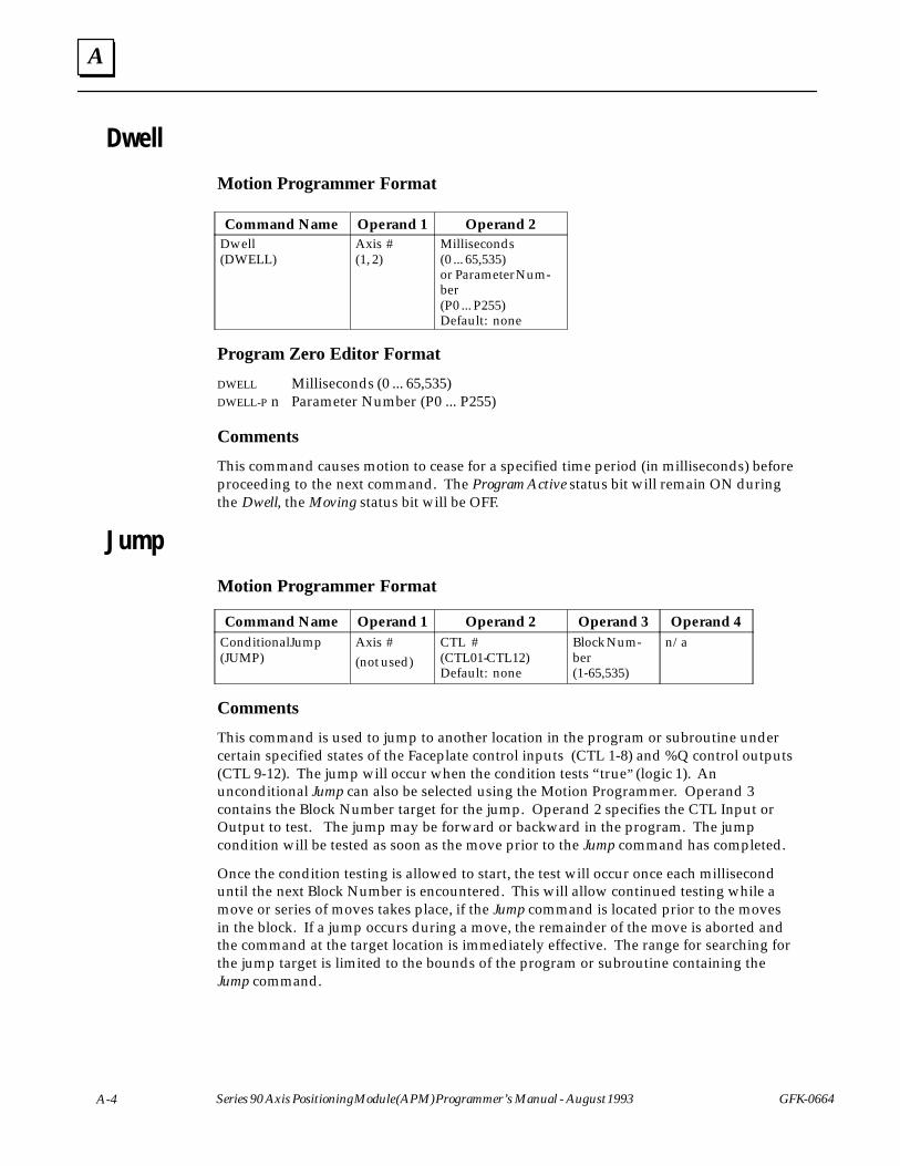
A
A-4 Series 90 Axis Positioning Module (APM) Programmer’s Manual - August 1993 GFK-0664
Dwell
Motion Programmer Format
ÁÁÁÁÁÁÁÁÁÁÁÁÁÁ
Command NameÁÁÁÁÁÁÁÁÁÁ
Operand 1ÁÁÁÁÁÁÁÁÁÁÁÁÁÁ
Operand 2ÁÁÁÁÁÁÁÁÁÁÁÁÁÁÁÁÁÁÁÁÁÁÁÁÁÁÁÁÁÁÁÁÁÁÁ
Dwell(DWELL)
ÁÁÁÁÁÁÁÁÁÁÁÁÁÁÁÁÁÁÁÁÁÁÁÁÁ
Axis #(1, 2)
ÁÁÁÁÁÁÁÁÁÁÁÁÁÁÁÁÁÁÁÁÁÁÁÁÁÁÁÁÁÁÁÁÁÁÁ
Milliseconds(0 ... 65,535)or Parameter Num-ber(P0 ... P255)Default: none
Program Zero Editor Format
DWELL Milliseconds (0 ... 65,535)DWELL-P n Parameter Number (P0 ... P255)
Comments
This command causes motion to cease for a specified time period (in milliseconds) beforeproceeding to the next command. The Program Active status bit will remain ON duringthe Dwell, the Moving status bit will be OFF.
Jump
Motion Programmer FormatÁÁÁÁÁÁÁÁÁÁÁÁÁÁCommand Name
ÁÁÁÁÁÁÁÁÁÁOperand 1
ÁÁÁÁÁÁÁÁÁÁÁÁÁÁOperand 2
ÁÁÁÁÁÁÁÁÁÁOperand 3
ÁÁÁÁÁÁÁÁÁÁOperand 4ÁÁÁÁÁÁÁ
ÁÁÁÁÁÁÁÁÁÁÁÁÁÁÁÁÁÁÁÁÁ
Conditional Jump(JUMP)
ÁÁÁÁÁÁÁÁÁÁÁÁÁÁÁÁÁÁÁÁ
Axis #(not used)
ÁÁÁÁÁÁÁÁÁÁÁÁÁÁÁÁÁÁÁÁÁÁÁÁÁÁÁÁ
CTL #(CTL01-CTL12)Default: none
ÁÁÁÁÁÁÁÁÁÁÁÁÁÁÁÁÁÁÁÁ
Block Num-ber(1-65,535)
ÁÁÁÁÁÁÁÁÁÁÁÁÁÁÁÁÁÁÁÁ
n/a
Comments
This command is used to jump to another location in the program or subroutine undercertain specified states of the Faceplate control inputs (CTL 1-8) and %Q control outputs(CTL 9-12). The jump will occur when the condition tests “true” (logic 1). Anunconditional Jump can also be selected using the Motion Programmer. Operand 3contains the Block Number target for the jump. Operand 2 specifies the CTL Input orOutput to test. The jump may be forward or backward in the program. The jumpcondition will be tested as soon as the move prior to the Jump command has completed.
Once the condition testing is allowed to start, the test will occur once each milliseconduntil the next Block Number is encountered. This will allow continued testing while amove or series of moves takes place, if the Jump command is located prior to the movesin the block. If a jump occurs during a move, the remainder of the move is aborted andthe command at the target location is immediately effective. The range for searching forthe jump target is limited to the bounds of the program or subroutine containing theJump command.
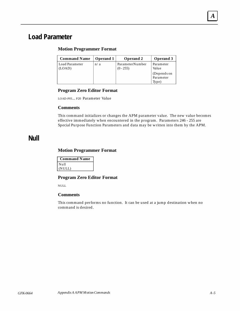
A
GFK-0664 A-5Appendix A APM Motion Commands
Load Parameter
Motion Programmer Format
ÁÁÁÁÁÁÁÁÁÁÁÁÁÁ
Command NameÁÁÁÁÁÁÁÁÁÁ
Operand 1ÁÁÁÁÁÁÁÁÁÁÁÁÁÁ
Operand 2 ÁÁÁÁÁÁÁÁÁÁ
Operand 3
ÁÁÁÁÁÁÁÁÁÁÁÁÁÁÁÁÁÁÁÁÁÁÁÁÁÁÁÁ
Load Parameter(LOAD)
ÁÁÁÁÁÁÁÁÁÁÁÁÁÁÁÁÁÁÁÁ
n/a ÁÁÁÁÁÁÁÁÁÁÁÁÁÁÁÁÁÁÁÁÁÁÁÁÁÁÁÁ
Parameter Number(0 - 255)
ÁÁÁÁÁÁÁÁÁÁÁÁÁÁÁÁÁÁÁÁ
ParameterValue(Depends onParameterType)
Program Zero Editor Format
LOAD-P01... P20 Parameter Value
Comments
This command initializes or changes the APM parameter value. The new value becomeseffective immediately when encountered in the program. Parameters 246 - 255 areSpecial Purpose Function Parameters and data may be written into them by the APM.
Null
Motion Programmer FormatÁÁÁÁÁÁÁÁÁÁÁÁÁÁCommand NameÁÁÁÁÁÁÁÁÁÁÁÁÁÁÁÁÁÁÁÁÁ
Null(NULL)
Program Zero Editor Format
NULL
Comments
This command performs no function. It can be used at a jump destination when nocommand is desired.
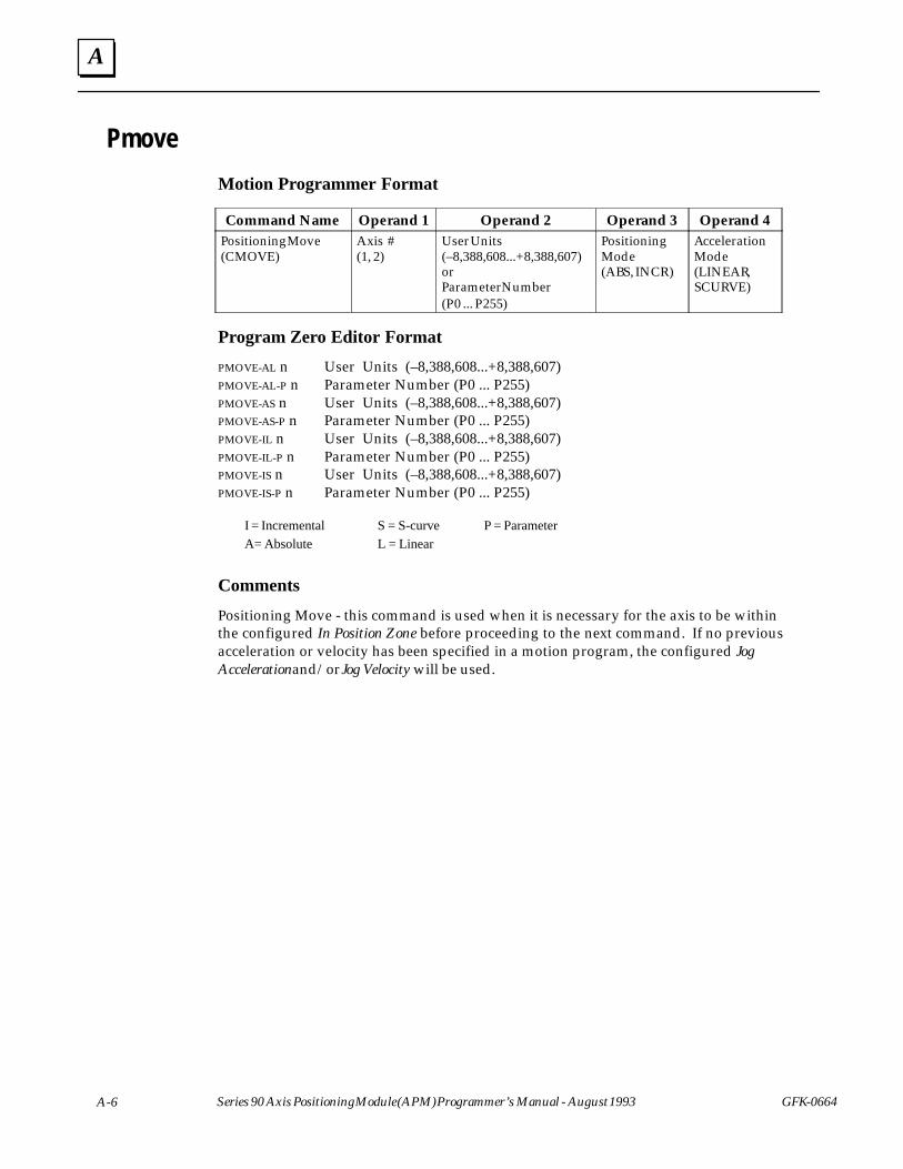
A
A-6 Series 90 Axis Positioning Module (APM) Programmer’s Manual - August 1993 GFK-0664
Pmove
Motion Programmer Format
ÁÁÁÁÁÁÁÁÁÁÁÁÁÁ
Command NameÁÁÁÁÁÁÁÁÁÁ
Operand 1ÁÁÁÁÁÁÁÁÁÁÁÁÁÁÁÁ
Operand 2 ÁÁÁÁÁÁÁÁÁÁ
Operand 3ÁÁÁÁÁÁÁÁÁÁ
Operand 4
ÁÁÁÁÁÁÁÁÁÁÁÁÁÁÁÁÁÁÁÁÁÁÁÁÁÁÁÁ
Positioning Move(CMOVE)
ÁÁÁÁÁÁÁÁÁÁÁÁÁÁÁÁÁÁÁÁ
Axis #(1, 2)
ÁÁÁÁÁÁÁÁÁÁÁÁÁÁÁÁÁÁÁÁÁÁÁÁÁÁÁÁÁÁÁÁ
User Units(–8,388,608...+8,388,607)orParameter Number(P0 ... P255)
ÁÁÁÁÁÁÁÁÁÁÁÁÁÁÁÁÁÁÁÁ
PositioningMode(ABS, INCR)
ÁÁÁÁÁÁÁÁÁÁÁÁÁÁÁÁÁÁÁÁ
AccelerationMode(LINEAR,SCURVE)
Program Zero Editor Format
PMOVE-AL n User Units (–8,388,608...+8,388,607)PMOVE-AL-P n Parameter Number (P0 ... P255)PMOVE-AS n User Units (–8,388,608...+8,388,607)PMOVE-AS-P n Parameter Number (P0 ... P255)PMOVE-IL n User Units (–8,388,608...+8,388,607)PMOVE-IL-P n Parameter Number (P0 ... P255)PMOVE-IS n User Units (–8,388,608...+8,388,607)PMOVE-IS-P n Parameter Number (P0 ... P255)
I = Incremental S = S-curve P = ParameterA= Absolute L = Linear
Comments
Positioning Move - this command is used when it is necessary for the axis to be withinthe configured In Position Zone before proceeding to the next command. If no previousacceleration or velocity has been specified in a motion program, the configured JogAcceleration and/or Jog Velocity will be used.
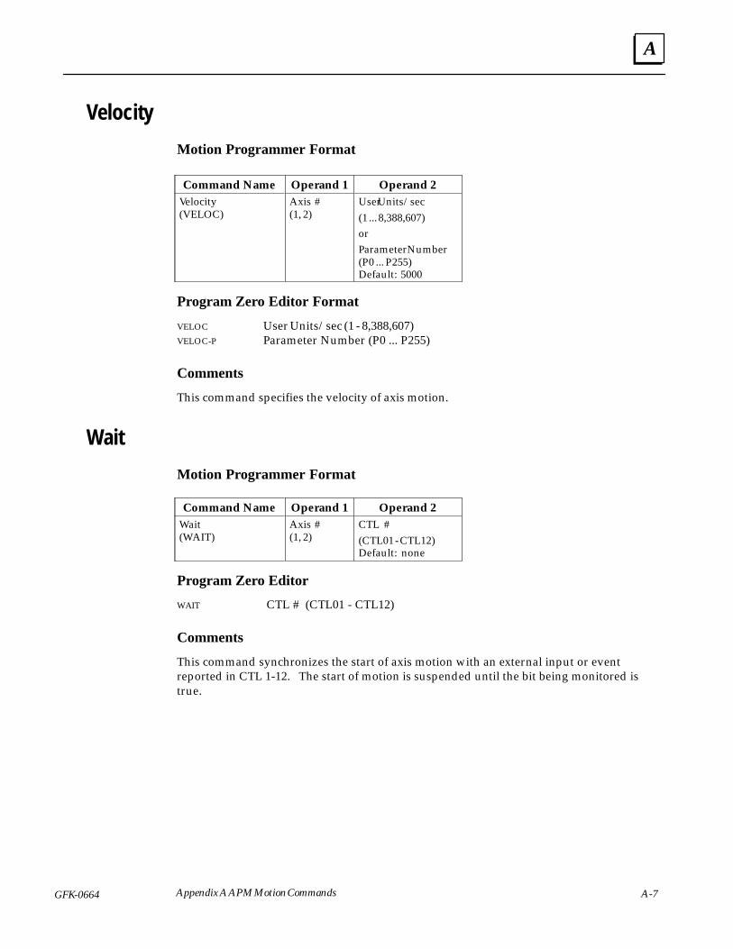
A
GFK-0664 A-7Appendix A APM Motion Commands
Velocity
Motion Programmer Format
ÁÁÁÁÁÁÁÁÁÁÁÁÁÁ
Command NameÁÁÁÁÁÁÁÁÁÁ
Operand 1ÁÁÁÁÁÁÁÁÁÁÁÁÁÁ
Operand 2ÁÁÁÁÁÁÁÁÁÁÁÁÁÁÁÁÁÁÁÁÁÁÁÁÁÁÁÁÁÁÁÁÁÁÁÁÁÁÁÁÁÁ
Velocity(VELOC)
ÁÁÁÁÁÁÁÁÁÁÁÁÁÁÁÁÁÁÁÁÁÁÁÁÁÁÁÁÁÁ
Axis #(1, 2)
ÁÁÁÁÁÁÁÁÁÁÁÁÁÁÁÁÁÁÁÁÁÁÁÁÁÁÁÁÁÁÁÁÁÁÁÁÁÁÁÁÁÁ
User Units/sec(1 ... 8,388,607)orParameter Number(P0 ... P255)Default: 5000
Program Zero Editor Format
VELOC User Units/sec (1 - 8,388,607)VELOC-P Parameter Number (P0 ... P255)
Comments
This command specifies the velocity of axis motion.
Wait
Motion Programmer FormatÁÁÁÁÁÁÁÁÁÁÁÁÁÁÁÁÁÁÁÁÁ
Command NameÁÁÁÁÁÁÁÁÁÁÁÁÁÁÁ
Operand 1ÁÁÁÁÁÁÁÁÁÁÁÁÁÁÁÁÁÁÁÁÁ
Operand 2ÁÁÁÁÁÁÁÁÁÁÁÁÁÁÁÁÁÁÁÁÁÁÁÁÁÁÁÁ
Wait(WAIT)
ÁÁÁÁÁÁÁÁÁÁÁÁÁÁÁÁÁÁÁÁ
Axis #(1, 2)
ÁÁÁÁÁÁÁÁÁÁÁÁÁÁÁÁÁÁÁÁÁÁÁÁÁÁÁÁ
CTL #(CTL01 - CTL12)Default: none
Program Zero Editor
WAIT CTL # (CTL01 - CTL12)
Comments
This command synchronizes the start of axis motion with an external input or eventreported in CTL 1-12. The start of motion is suspended until the bit being monitored istrue.
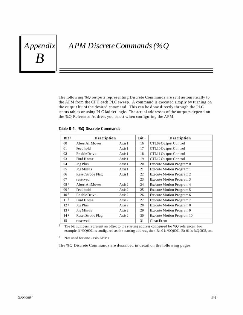
Bsection level 1 1figure_ap level 1 table_ap level 1
B-1GFK-0664
Appendix B APM Discrete Commands (%Q
The following %Q outputs representing Discrete Commands are sent automatically tothe APM from the CPU each PLC sweep. A command is executed simply by turning onthe output bit of the desired command. This can be done directly through the PLCstatus tables or using PLC ladder logic. The actual addresses of the outputs depend onthe %Q Reference Address you select when configuring the APM.
Table B-1. %Q Discrete CommandsÁÁÁÁÁÁÁÁÁÁÁÁ
Bit 1ÁÁÁÁÁÁÁÁÁÁÁÁÁÁÁÁÁÁÁÁÁÁÁÁÁÁÁÁÁÁÁÁÁ
DescriptionÁÁÁÁÁÁÁÁÁ
Bit 1ÁÁÁÁÁÁÁÁÁÁÁÁÁÁÁÁÁÁÁÁÁÁÁÁÁÁÁÁÁÁÁÁÁ
DescriptionÁÁÁÁÁÁÁÁ00
ÁÁÁÁÁÁÁÁÁÁÁÁÁÁÁÁÁÁÁÁÁÁAbort All Moves Axis 1
ÁÁÁÁÁÁ16
ÁÁÁÁÁÁÁÁÁÁÁÁÁÁÁÁÁÁÁÁÁÁCTL09 Output ControlÁÁÁÁ
ÁÁÁÁ01ÁÁÁÁÁÁÁÁÁÁÁÁÁÁÁÁÁÁÁÁÁÁFeedhold Axis 1
ÁÁÁÁÁÁ17
ÁÁÁÁÁÁÁÁÁÁÁÁÁÁÁÁÁÁÁÁÁÁCTL10 Output ControlÁÁÁÁ
ÁÁÁÁ02 ÁÁÁÁÁÁÁÁÁÁÁÁÁÁÁÁÁÁÁÁÁÁ
Enable Drive Axis 1 ÁÁÁÁÁÁ
18 ÁÁÁÁÁÁÁÁÁÁÁÁÁÁÁÁÁÁÁÁÁÁ
CTL11 Output ControlÁÁÁÁÁÁÁÁ
03 ÁÁÁÁÁÁÁÁÁÁÁÁÁÁÁÁÁÁÁÁÁÁ
Find Home Axis 1 ÁÁÁÁÁÁ
19 ÁÁÁÁÁÁÁÁÁÁÁÁÁÁÁÁÁÁÁÁÁÁ
CTL12 Output ControlÁÁÁÁÁÁÁÁ
04 ÁÁÁÁÁÁÁÁÁÁÁÁÁÁÁÁÁÁÁÁÁÁ
Jog Plus Axis 1 ÁÁÁÁÁÁ
20 ÁÁÁÁÁÁÁÁÁÁÁÁÁÁÁÁÁÁÁÁÁÁ
Execute Motion Program 0
ÁÁÁÁÁÁÁÁ
05 ÁÁÁÁÁÁÁÁÁÁÁÁÁÁÁÁÁÁÁÁÁÁ
Jog Minus Axis 1 ÁÁÁÁÁÁ
21 ÁÁÁÁÁÁÁÁÁÁÁÁÁÁÁÁÁÁÁÁÁÁ
Execute Motion Program 1
ÁÁÁÁ06 ÁÁÁÁÁÁÁÁÁÁÁReset Strobe Flag Axis 1 ÁÁÁ22 ÁÁÁÁÁÁÁÁÁÁÁExecute Motion Program 2ÁÁÁÁÁÁÁÁ07
ÁÁÁÁÁÁÁÁÁÁÁÁÁÁÁÁÁÁÁÁÁÁreserved
ÁÁÁÁÁÁ23
ÁÁÁÁÁÁÁÁÁÁÁÁÁÁÁÁÁÁÁÁÁÁExecute Motion Program 3ÁÁÁÁ
ÁÁÁÁ08 2ÁÁÁÁÁÁÁÁÁÁÁÁÁÁÁÁÁÁÁÁÁÁ
Abort All Moves Axis 2ÁÁÁÁÁÁ
24ÁÁÁÁÁÁÁÁÁÁÁÁÁÁÁÁÁÁÁÁÁÁ
Execute Motion Program 4ÁÁÁÁÁÁÁÁ
09 2 ÁÁÁÁÁÁÁÁÁÁÁÁÁÁÁÁÁÁÁÁÁÁ
Feedhold Axis 2 ÁÁÁÁÁÁ
25 ÁÁÁÁÁÁÁÁÁÁÁÁÁÁÁÁÁÁÁÁÁÁ
Execute Motion Program 5ÁÁÁÁÁÁÁÁ
10 2 ÁÁÁÁÁÁÁÁÁÁÁÁÁÁÁÁÁÁÁÁÁÁ
Enable Drive Axis 2 ÁÁÁÁÁÁ
26 ÁÁÁÁÁÁÁÁÁÁÁÁÁÁÁÁÁÁÁÁÁÁ
Execute Motion Program 6
ÁÁÁÁÁÁÁÁ
11 2 ÁÁÁÁÁÁÁÁÁÁÁÁÁÁÁÁÁÁÁÁÁÁ
Find Home Axis 2 ÁÁÁÁÁÁ
27 ÁÁÁÁÁÁÁÁÁÁÁÁÁÁÁÁÁÁÁÁÁÁ
Execute Motion Program 7
ÁÁÁÁÁÁÁÁ
12 2 ÁÁÁÁÁÁÁÁÁÁÁÁÁÁÁÁÁÁÁÁÁÁ
Jog Plus Axis 2 ÁÁÁÁÁÁ
28 ÁÁÁÁÁÁÁÁÁÁÁÁÁÁÁÁÁÁÁÁÁÁ
Execute Motion Program 8ÁÁÁÁÁÁÁÁ13 2
ÁÁÁÁÁÁÁÁÁÁÁÁÁÁÁÁÁÁÁÁÁÁJog Minus Axis 2
ÁÁÁÁÁÁ29
ÁÁÁÁÁÁÁÁÁÁÁÁÁÁÁÁÁÁÁÁÁÁExecute Motion Program 9ÁÁÁÁ
ÁÁÁÁ14 2ÁÁÁÁÁÁÁÁÁÁÁÁÁÁÁÁÁÁÁÁÁÁ
Reset Strobe Flag Axis 2ÁÁÁÁÁÁ
30ÁÁÁÁÁÁÁÁÁÁÁÁÁÁÁÁÁÁÁÁÁÁ
Execute Motion Program 10ÁÁÁÁÁÁÁÁ
15 ÁÁÁÁÁÁÁÁÁÁÁÁÁÁÁÁÁÁÁÁÁÁ
reserved ÁÁÁÁÁÁ
31 ÁÁÁÁÁÁÁÁÁÁÁÁÁÁÁÁÁÁÁÁÁÁ
Clear Error1 The bit numbers represent an offset to the starting address configured for %Q references. For
example, if %Q0001 is configured as the starting address, then Bit 0 is %Q0001, Bit 01 is %Q0002, etc.
2 Not used for one - axis APMs.
The %Q Discrete Commands are described in detail on the following pages.
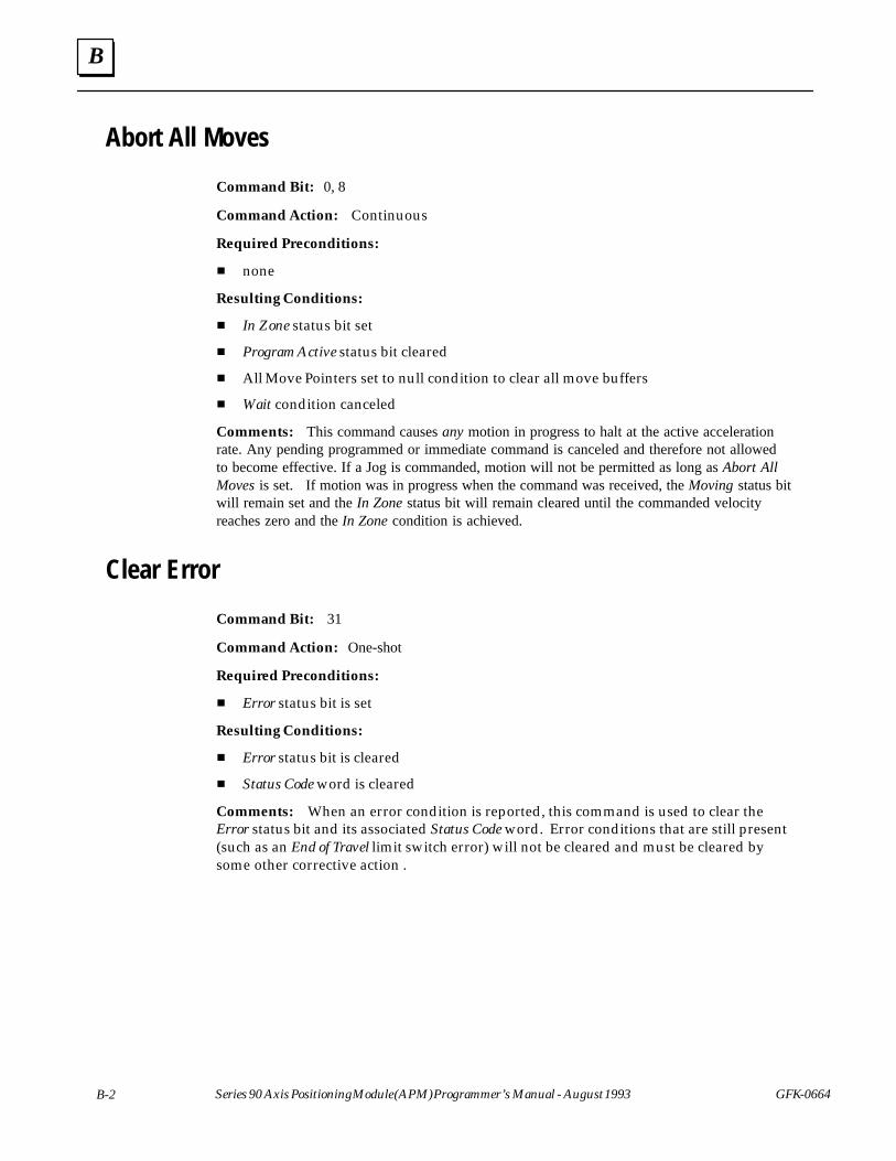
B
B-2 Series 90 Axis Positioning Module (APM) Programmer’s Manual - August 1993 GFK-0664
Abort All Moves
Command Bit: 0, 8
Command Action: Continuous
Required Preconditions:
� none
Resulting Conditions:
� In Zone status bit set
� Program Active status bit cleared
� All Move Pointers set to null condition to clear all move buffers
� Wait condition canceled
Comments: This command causes any motion in progress to halt at the active accelerationrate. Any pending programmed or immediate command is canceled and therefore not allowedto become effective. If a Jog is commanded, motion will not be permitted as long as Abort AllMoves is set. If motion was in progress when the command was received, the Moving status bitwill remain set and the In Zone status bit will remain cleared until the commanded velocityreaches zero and the In Zone condition is achieved.
Clear Error
Command Bit: 31
Command Action: One-shot
Required Preconditions:
� Error status bit is set
Resulting Conditions:
� Error status bit is cleared
� Status Code word is cleared
Comments: When an error condition is reported, this command is used to clear theError status bit and its associated Status Code word. Error conditions that are still present(such as an End of Travel limit switch error) will not be cleared and must be cleared bysome other corrective action .
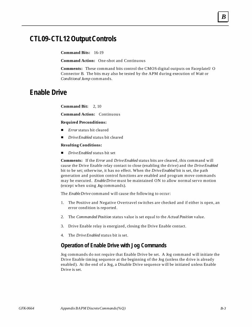
B
GFK-0664 B-3Appendix B APM Discrete Commands (%Q)
CTL09-CTL12 Output Controls
Command Bits: 16-19
Command Action: One-shot and Continuous
Comments: These command bits control the CMOS digital outputs on Faceplate I/OConnector B. The bits may also be tested by the APM during execution of Wait orConditional Jump commands.
Enable Drive
Command Bit: 2, 10
Command Action: Continuous
Required Preconditions:
� Error status bit cleared
� Drive Enabled status bit cleared
Resulting Conditions:
� Drive Enabled status bit set
Comments: If the Error and Drive Enabled status bits are cleared, this command willcause the Drive Enable relay contact to close (enabling the drive) and the Drive Enabledbit to be set; otherwise, it has no effect. When the Drive Enabled bit is set, the pathgeneration and position control functions are enabled and program move commandsmay be executed. Enable Drive must be maintained ON to allow normal servo motion(except when using Jog commands).
The Enable Drive command will cause the following to occur:
1. The Positive and Negative Overtravel switches are checked and if either is open, anerror condition is reported.
2. The Commanded Position status value is set equal to the Actual Position value.
3. Drive Enable relay is energized, closing the Drive Enable contact.
4. The Drive Enabled status bit is set.
Operation of Enable Drive with Jog CommandsJog commands do not require that Enable Drive be set. A Jog command will initiate theDrive Enable timing sequence at the beginning of the Jog (unless the drive is alreadyenabled). At the end of a Jog, a Disable Drive sequence will be initiated unless EnableDrive is set.
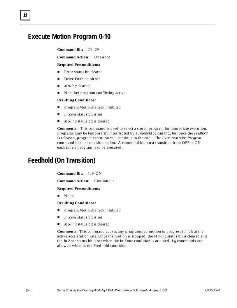
B
B-4 Series 90 Axis Positioning Module (APM) Programmer’s Manual - August 1993 GFK-0664
Execute Motion Program 0-10
Command Bit: 20 - 29
Command Action: One-shot
Required Preconditions:
� Error status bit cleared
� Drive Enabled bit set
� Moving cleared
� No other program conflicting active
Resulting Conditions:
� Program Motion halted/inhibited
� In Zone status bit is set
� Moving status bit is cleared
Comments: This command is used to select a stored program for immediate execution.Programs may be temporarily interrupted by a Feedhold command, but once the Feedholdis released, program execution will continue to the end. The Execute Motion Programcommand bits use one shot action. A command bit must transition from OFF to ONeach time a program is to be executed.
Feedhold (On Transition)
Command Bit: 1, 9 ON
Command Action: Continuous
Required Preconditions:
� None
Resulting Conditions:
� Program Motion halted/inhibited
� In Zone status bit is set
� Moving status bit is cleared
Comments: This command causes any programmed motion in progress to halt at theactive acceleration rate. Once the motion is stopped, the Moving status bit is cleared andthe In Zone status bit is set when the In Zone condition is attained. Jog commands areallowed when in the Feedhold condition.
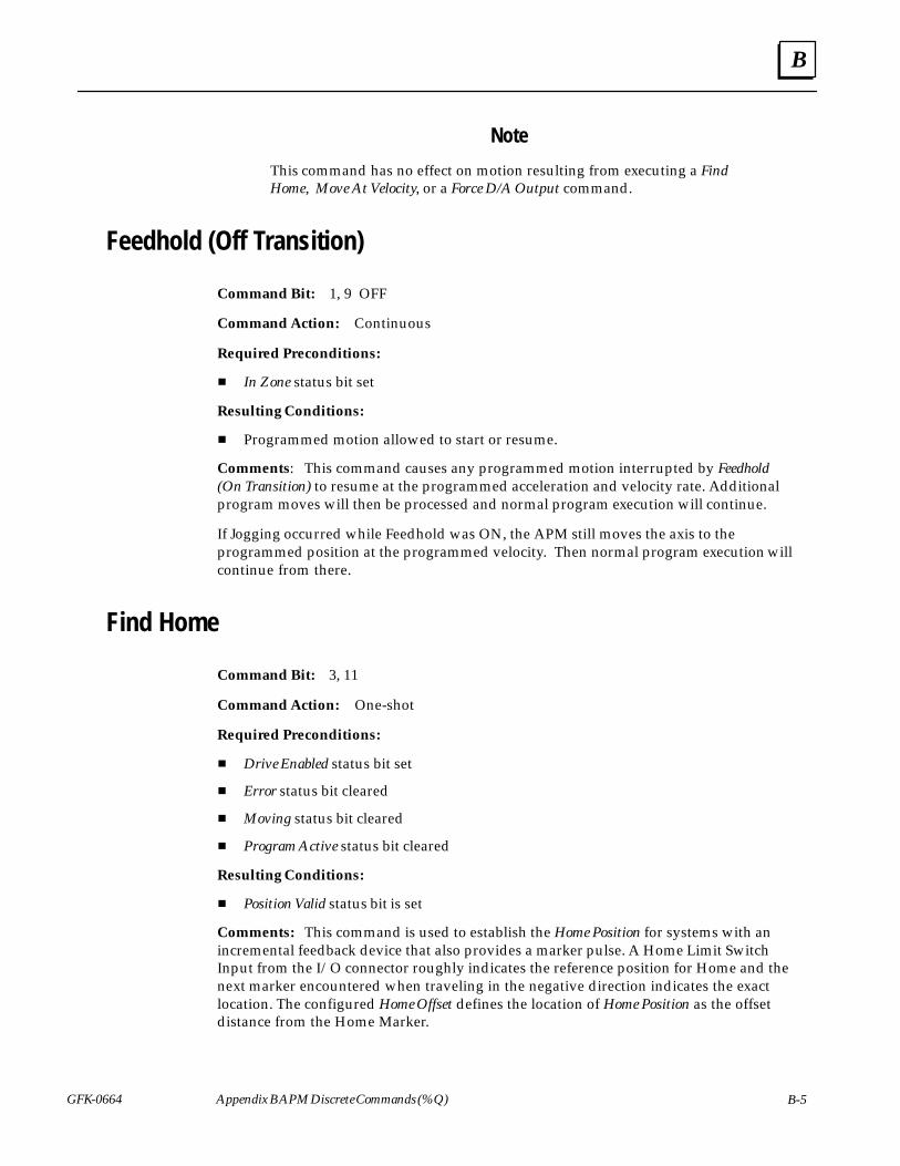
B
GFK-0664 B-5Appendix B APM Discrete Commands (%Q)
Note
This command has no effect on motion resulting from executing a FindHome, Move At Velocity, or a Force D/A Output command.
Feedhold (Off Transition)
Command Bit: 1, 9 OFF
Command Action: Continuous
Required Preconditions:
� In Zone status bit set
Resulting Conditions:
� Programmed motion allowed to start or resume.
Comments: This command causes any programmed motion interrupted by Feedhold(On Transition) to resume at the programmed acceleration and velocity rate. Additionalprogram moves will then be processed and normal program execution will continue.
If Jogging occurred while Feedhold was ON, the APM still moves the axis to theprogrammed position at the programmed velocity. Then normal program execution willcontinue from there.
Find Home
Command Bit: 3, 11
Command Action: One-shot
Required Preconditions:
� Drive Enabled status bit set
� Error status bit cleared
� Moving status bit cleared
� Program Active status bit cleared
Resulting Conditions:
� Position Valid status bit is set
Comments: This command is used to establish the Home Position for systems with anincremental feedback device that also provides a marker pulse. A Home Limit SwitchInput from the I/O connector roughly indicates the reference position for Home and thenext marker encountered when traveling in the negative direction indicates the exactlocation. The configured Home Offset defines the location of Home Position as the offsetdistance from the Home Marker.
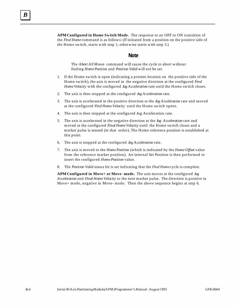
B
B-6 Series 90 Axis Positioning Module (APM) Programmer’s Manual - August 1993 GFK-0664
APM Configured in Home Switch Mode. The response to an OFF to ON transition ofthe Find Home command is as follows: (If initiated from a position on the positive side ofthe Home switch, starts with step 1, otherwise starts with step 3.)
Note
The Abort All Moves command will cause the cycle to abort withoutfinding Home Position and Position Valid will not be set.
1. If the Home switch is open (indicating a present location on the positive side of theHome switch), the axis is moved in the negative direction at the configured FindHome Velocity with the configured Jog Acceleration rate until the Home switch closes.
2. The axis is then stopped at the configured Jog Acceleration rate.
3. The axis is accelerated in the positive direction at the Jog Acceleration rate and movedat the configured Find Home Velocity until the Home switch opens.
4. The axis is then stopped at the configured Jog Acceleration rate.
5. The axis is accelerated in the negative direction at the Jog Acceleration rate andmoved at the configured Final Home Velocity until the Home switch closes and amarker pulse is sensed (in that order). The Home reference position is established atthis point.
6. The axis is stopped at the configured Jog Acceleration rate.
7. The axis is moved to the Home Position (which is indicated by the Home Offset valuefrom the reference marker position). An internal Set Position is then performed toinsert the configured Home Position value.
8. The Position Valid status bit is set indicating that the Find Home cycle is complete.
APM Configured in Move+ or Move- mode. The axis moves at the configured JogAcceleration and Final Home Velocity to the next marker pulse. The direction is positive inMove+ mode, negative in Move- mode. Then the above sequence begins at step 6.
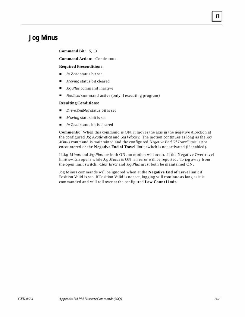
B
GFK-0664 B-7Appendix B APM Discrete Commands (%Q)
Jog Minus
Command Bit: 5, 13
Command Action: Continuous
Required Preconditions:
� In Zone status bit set
� Moving status bit cleared
� Jog Plus command inactive
� Feedhold command active (only if executing program)
Resulting Conditions:
� Drive Enabled status bit is set
� Moving status bit is set
� In Zone status bit is cleared
Comments: When this command is ON, it moves the axis in the negative direction atthe configured Jog Acceleration and Jog Velocity. The motion continues as long as the JogMinus command is maintained and the configured Negative End Of Travel limit is notencountered or the Negative End of Travel limit switch is not activated (if enabled).
If Jog Minus and Jog Plus are both ON, no motion will occur. If the Negative Overtravellimit switch opens while Jog Minus is ON, an error will be reported. To jog away fromthe open limit switch, Clear Error and Jog Plus must both be maintained ON.
Jog Minus commands will be ignored when at the Negative End of Travel limit ifPosition Valid is set. If Position Valid is not set, Jogging will continue as long as it iscommanded and will roll over at the configured Low Count Limit.
B
B-8 Series 90 Axis Positioning Module (APM) Programmer’s Manual - August 1993 GFK-0664
Jog Plus
Command Bit: 4, 12
Command Action: Continuous
Required Preconditions:
� In Zone status bit set
� Moving status bit cleared
� Jog Minus command inactive
� Feedhold command active (only if executing program)
Resulting Conditions:
� In Zone status bit is cleared
� Moving status bit is set
� Drive Enabled status bit is set
Comments: When this command is ON it moves the axis in the positive direction atthe configured Jog Acceleration and Jog Velocity. The motion continues as long as the JogPlus command is maintained and the configured Positive End Of Travel limit is notencountered or the Positive End of Travel limit switch is not activated (if enabled).
If Jog Minus and Jog Plus are both ON, no motion will occur. If the Positive Overtravellimit switch opens while Jog Plus is ON, an error will be reported. To jog away from theopen limit switch, Clear Error and Jog Minus must both be maintained ON.
Jog Plus commands will be ignored when at the Positive End of Travel limit if PositionValid is set. If Position Valid is not set, Jogging will continue as long as it is commandedand will roll over at the configured High Count Limit.
B
GFK-0664 B-9Appendix B APM Discrete Commands (%Q)
Reset Strobe Flag
Command Bit: 6, 14
Command Action: Continuous
Required Preconditions:
Resulting Conditions:
� Strobe Flag status bit cleared
Comments: The Strobe Flag status bit informs the PLC that a Strobe Input has capturedan axis position that is now stored in the Strobe Position status word. When the PLCacknowledges this data, it may use the Reset Strobe Flag command to clear the Strobe Flagstatus bit. Once the Strobe Flag bit is set, additional Strobe Inputs will not cause new datato be captured. The flag must be cleared before another Strobe Position will be captured.As long as the Reset Strobe Flag command is active, the Strobe Flag bit will be held in thecleared state. In this condition, the latest Strobe Input position is reflected in the StrobePosition status word, although the flag cannot be used by the PLC to indicate when newdata is present.
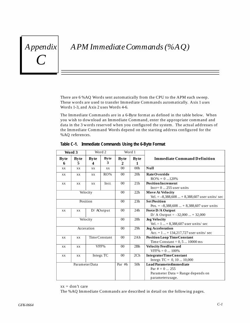
C section level 1 1figure_ap level 1 table_ap level 1
C-1GFK-0664
Appendix C APM Immediate Commands (%AQ)
There are 6 %AQ Words sent automatically from the CPU to the APM each sweep.These words are used to transfer Immediate Commands automatically. Axis 1 usesWords 1-3, and Axis 2 uses Words 4-6.
The Immediate Commands are in a 6-Byte format as defined in the table below. Whenyou wish to download an Immediate Command, enter the appropriate command anddata in the 3 words reserved when you configured the system. The actual addresses ofthe Immediate Command Words depend on the starting address configured for the%AQ references.
Table C-1. Immediate Commands Using the 6-Byte FormatÁÁÁÁÁÁÁÁÁÁÁÁWord 3
ÁÁÁÁÁÁÁÁÁÁÁÁ
Word 2ÁÁÁÁÁÁÁÁÁÁÁÁ
Word 1ÁÁÁÁÁÁÁÁÁÁÁÁÁÁÁÁÁÁÁÁÁÁÁÁÁÁÁÁÁÁ
ÁÁÁÁÁÁÁÁ
Byte 6
ÁÁÁÁÁÁÁÁÁ
Byte5
ÁÁÁÁÁÁÁÁÁÁÁÁ
Byte4
ÁÁÁÁÁÁÁÁÁ
Byte3
ÁÁÁÁÁÁÁÁÁ
Byte2
ÁÁÁÁÁÁÁÁÁÁÁÁ
Byte1
ÁÁÁÁÁÁÁÁÁÁÁÁÁÁÁÁÁÁÁÁÁÁÁÁÁÁÁÁÁÁÁÁÁÁÁÁÁÁÁ
Immediate Command Definition
ÁÁÁÁÁÁÁÁ
xx ÁÁÁÁÁÁ
xxÁÁÁÁÁÁÁÁ
xx ÁÁÁÁÁÁ
xx ÁÁÁÁÁÁ
00ÁÁÁÁÁÁÁÁ
00h ÁÁÁÁÁÁÁÁÁÁÁÁÁÁÁÁÁÁÁÁÁÁÁÁÁÁNull
ÁÁÁÁÁÁÁÁ
xx ÁÁÁÁÁÁ
xxÁÁÁÁÁÁÁÁ
xx ÁÁÁÁÁÁ
RO%ÁÁÁÁÁÁ
00ÁÁÁÁÁÁÁÁ
20h ÁÁÁÁÁÁÁÁÁÁÁÁÁÁÁÁÁÁÁÁÁÁÁÁÁÁ
Rate OverrideRO% = 0 ...120%ÁÁÁÁ
ÁÁÁÁÁÁÁÁ
xxÁÁÁÁÁÁÁÁÁ
xxÁÁÁÁÁÁÁÁÁÁÁÁ
xxÁÁÁÁÁÁÁÁÁ
Incr.ÁÁÁÁÁÁÁÁÁ
00ÁÁÁÁÁÁÁÁÁÁÁÁ
21hÁÁÁÁÁÁÁÁÁÁÁÁÁÁÁÁÁÁÁÁÁÁÁÁÁÁÁÁÁÁÁÁÁÁÁÁÁÁÁ
Position IncrementIncr= 0 ... 255 user units
ÁÁÁÁÁÁÁÁÁÁÁÁÁÁÁÁÁÁÁÁÁÁ
Velocity ÁÁÁÁÁÁ
00ÁÁÁÁÁÁÁÁ
22h ÁÁÁÁÁÁÁÁÁÁÁÁÁÁÁÁÁÁÁÁÁÁÁÁÁÁMove At Velocity
Vel. = –8,388,608 ... + 8,388,607 user units/secÁÁÁÁÁÁÁÁÁÁÁÁÁÁÁÁÁÁÁÁÁÁÁÁÁÁÁÁÁÁÁÁÁ
Position ÁÁÁÁÁÁÁÁÁ
00ÁÁÁÁÁÁÁÁÁÁÁÁ
23h ÁÁÁÁÁÁÁÁÁÁÁÁÁÁÁÁÁÁÁÁÁÁÁÁÁÁÁÁÁÁÁÁÁÁÁÁÁÁÁ
Set PositionPos. = –8,388,608 ... + 8,388,607 user units
ÁÁÁÁÁÁÁÁ
xx ÁÁÁÁÁÁ
xxÁÁÁÁÁÁÁÁÁÁÁÁ
D/A Output ÁÁÁÁÁÁ
00ÁÁÁÁÁÁÁÁ
24h ÁÁÁÁÁÁÁÁÁÁÁÁÁÁÁÁÁÁÁÁÁÁÁÁÁÁForce D/A Output
D/A Output = –32,000 ... + 32,000ÁÁÁÁÁÁÁÁÁÁÁÁÁÁÁÁÁÁÁÁÁÁÁÁÁÁÁÁÁÁÁÁÁ
Velocity ÁÁÁÁÁÁÁÁÁ
00ÁÁÁÁÁÁÁÁÁÁÁÁ
28h ÁÁÁÁÁÁÁÁÁÁÁÁÁÁÁÁÁÁÁÁÁÁÁÁÁÁÁÁÁÁÁÁÁÁÁÁÁÁÁ
Jog VelocityVel. = 1 ... + 8,388,607 user units/sec
ÁÁÁÁÁÁÁÁÁÁÁÁÁÁÁÁÁÁÁÁÁÁ
Acceration ÁÁÁÁÁÁ
00ÁÁÁÁÁÁÁÁ
29h ÁÁÁÁÁÁÁÁÁÁÁÁÁÁÁÁÁÁÁÁÁÁÁÁÁÁ
Jog AccelerationAcc. = 1 ... + 134,217,727 user units/sec
ÁÁÁÁÁÁÁÁÁÁÁÁ
xx ÁÁÁÁÁÁÁÁÁ
xxÁÁÁÁÁÁÁÁÁÁÁÁÁÁÁÁÁÁ
Time ConstantÁÁÁÁÁÁÁÁÁ
00ÁÁÁÁÁÁÁÁÁÁÁÁ
2Ah ÁÁÁÁÁÁÁÁÁÁÁÁÁÁÁÁÁÁÁÁÁÁÁÁÁÁÁÁÁÁÁÁÁÁÁÁÁÁÁ
Position Loop Time ConstantTime Constant = 0, 5 ... 10000 msÁÁÁÁ
ÁÁÁÁÁÁÁÁ
xxÁÁÁÁÁÁÁÁÁ
xxÁÁÁÁÁÁÁÁÁÁÁÁÁÁÁÁÁÁ
VFF%ÁÁÁÁÁÁÁÁÁ
00ÁÁÁÁÁÁÁÁÁÁÁÁ
2BhÁÁÁÁÁÁÁÁÁÁÁÁÁÁÁÁÁÁÁÁÁÁÁÁÁÁÁÁÁÁÁÁÁÁÁÁÁÁÁ
Velocity FeedforwardVFF% = 0 ... 100%
ÁÁÁÁÁÁÁÁ
xx ÁÁÁÁÁÁ
xxÁÁÁÁÁÁÁÁÁÁÁÁ
Integr. TC ÁÁÁÁÁÁ
00ÁÁÁÁÁÁÁÁ
2Ch ÁÁÁÁÁÁÁÁÁÁÁÁÁÁÁÁÁÁÁÁÁÁÁÁÁÁIntegrator Time Constant
Integr. TC = 0, 10 ... 10,000ÁÁÁÁÁÁÁÁÁÁÁÁÁÁÁÁÁÁÁÁÁÁÁÁÁÁÁÁÁÁÁÁÁÁÁÁÁÁÁÁÁÁÁÁ
Parameter DataÁÁÁÁÁÁÁÁÁÁÁÁ
Par #hÁÁÁÁÁÁÁÁÁÁÁÁÁÁÁÁ
50hÁÁÁÁÁÁÁÁÁÁÁÁÁÁÁÁÁÁÁÁÁÁÁÁÁÁÁÁÁÁÁÁÁÁÁÁÁÁÁÁÁÁÁÁÁÁÁÁÁÁÁÁ
Load Parameter ImmediatePar # = 0 ... 255Parameter Data = Range depends on parameter usage.
xx = don’t careThe %AQ Immediate Commands are described in detail on the following pages.
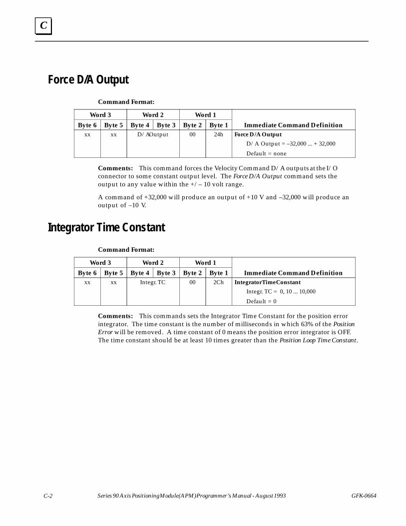
C
C-2 Series 90 Axis Positioning Module (APM) Programmer’s Manual - August 1993 GFK-0664
Force D/A Output
Command Format:ÁÁÁÁÁÁÁÁÁÁÁÁ
Word 3ÁÁÁÁÁÁÁÁÁÁÁÁ
Word 2ÁÁÁÁÁÁÁÁÁÁÁÁ
Word 1ÁÁÁÁÁÁÁÁÁÁÁÁÁÁÁÁÁÁÁÁÁÁÁÁÁÁÁÁÁ
ÁÁÁByte 6ÁÁÁÁÁÁÁÁ
Byte 5ÁÁÁÁÁÁÁÁ
Byte 4ÁÁÁÁÁÁ
Byte 3ÁÁÁÁÁÁÁÁ
Byte 2ÁÁÁÁÁÁ
Byte 1ÁÁÁÁÁÁÁÁÁÁÁÁÁÁÁÁÁÁÁÁÁÁÁÁÁÁ
Immediate Command DefinitionÁÁÁÁÁÁÁÁÁÁÁÁ
xxÁÁÁÁÁÁÁÁÁÁÁÁÁÁÁÁ
xxÁÁÁÁÁÁÁÁÁÁÁÁÁÁÁÁÁÁÁÁÁÁÁÁ
D/A OutputÁÁÁÁÁÁÁÁÁÁÁÁÁÁÁÁ
00ÁÁÁÁÁÁÁÁÁÁÁÁ
24hÁÁÁÁÁÁÁÁÁÁÁÁÁÁÁÁÁÁÁÁÁÁÁÁÁÁÁÁÁÁÁÁÁÁÁÁÁÁÁÁÁÁÁÁÁÁÁÁÁÁÁÁ
Force D/A Output
D/A Output = –32,000 ... + 32,000
Default = none
Comments: This command forces the Velocity Command D/A outputs at the I/Oconnector to some constant output level. The Force D/A Output command sets theoutput to any value within the +/– 10 volt range.
A command of +32,000 will produce an output of +10 V and –32,000 will produce anoutput of –10 V.
Integrator Time Constant
Command Format:
ÁÁÁÁÁÁÁÁÁÁÁÁ
Word 3 ÁÁÁÁÁÁÁÁÁÁÁÁ
Word 2 ÁÁÁÁÁÁÁÁÁÁÁÁ
Word 1 ÁÁÁÁÁÁÁÁÁÁÁÁÁÁÁÁÁÁÁÁÁÁÁÁÁÁÁÁÁ
ÁÁÁByte 6ÁÁÁÁÁÁÁÁ
Byte 5ÁÁÁÁÁÁÁÁ
Byte 4 ÁÁÁÁÁÁ
Byte 3ÁÁÁÁÁÁÁÁ
Byte 2ÁÁÁÁÁÁ
Byte 1ÁÁÁÁÁÁÁÁÁÁÁÁÁÁÁÁÁÁÁÁÁÁÁÁÁÁ
Immediate Command Definition
ÁÁÁÁÁÁÁÁÁ
xxÁÁÁÁÁÁÁÁÁÁÁÁ
xx ÁÁÁÁÁÁÁÁÁÁÁÁÁÁÁÁÁÁ
Integr. TC ÁÁÁÁÁÁÁÁÁÁÁÁ
00 ÁÁÁÁÁÁÁÁÁ
2ChÁÁÁÁÁÁÁÁÁÁÁÁÁÁÁÁÁÁÁÁÁÁÁÁÁÁÁÁÁÁÁÁÁÁÁÁÁÁÁ
Integrator Time Constant
Integr. TC = 0, 10 ... 10,000
Default = 0
Comments: This commands sets the Integrator Time Constant for the position errorintegrator. The time constant is the number of milliseconds in which 63% of the PositionError will be removed. A time constant of 0 means the position error integrator is OFF.The time constant should be at least 10 times greater than the Position Loop Time Constant.

C
GFK-0664 C-3Appendix C APM Immediate Commands (%AQ)
Jog Acceleration
Command Format: ÁÁÁÁÁÁÁÁÁÁÁÁÁÁÁÁÁÁ
Word 3ÁÁÁÁÁÁÁÁÁÁÁÁÁÁÁÁÁÁ
Word 2ÁÁÁÁÁÁÁÁÁÁÁÁÁÁÁÁÁÁ
Word 1ÁÁÁÁÁÁÁÁÁÁÁÁÁÁÁÁÁÁÁÁÁÁÁÁÁÁÁÁÁÁÁÁÁÁÁÁÁÁÁ
ÁÁÁÁÁÁÁÁÁ
Byte 6ÁÁÁÁÁÁÁÁÁÁÁÁ
Byte 5ÁÁÁÁÁÁÁÁÁÁÁÁ
Byte 4ÁÁÁÁÁÁÁÁÁ
Byte 3ÁÁÁÁÁÁÁÁÁÁÁÁ
Byte 2ÁÁÁÁÁÁÁÁÁ
Byte 1ÁÁÁÁÁÁÁÁÁÁÁÁÁÁÁÁÁÁÁÁÁÁÁÁÁÁÁÁÁÁÁÁÁÁÁÁÁÁÁ
Immediate Command DefinitionÁÁÁÁÁÁÁÁÁÁÁÁÁÁÁÁÁÁÁÁÁÁÁÁÁÁÁÁÁÁÁÁÁÁÁÁÁÁÁÁÁÁÁÁ
AccelerationÁÁÁÁÁÁÁÁÁÁÁÁÁÁÁÁ
00ÁÁÁÁÁÁÁÁÁÁÁÁ
29hÁÁÁÁÁÁÁÁÁÁÁÁÁÁÁÁÁÁÁÁÁÁÁÁÁÁÁÁÁÁÁÁÁÁÁÁÁÁÁÁÁÁÁÁÁÁÁÁÁÁÁÁ
Jog Acceleration
Acc. = 1 ... +134,217,727Default = 10,000
Comments: This command sets the acceleration used for Jog, Move at Velocity, Find Home,Abort, and Jump stops.
Jog Velocity
Command Format:
ÁÁÁÁÁÁÁÁÁÁÁÁ
Word 3 ÁÁÁÁÁÁÁÁÁÁÁÁ
Word 2 ÁÁÁÁÁÁÁÁÁÁÁÁ
Word 1 ÁÁÁÁÁÁÁÁÁÁÁÁÁÁÁÁÁÁÁÁÁÁÁÁÁÁÁÁÁ
ÁÁÁByte 6ÁÁÁÁÁÁÁÁ
Byte 5ÁÁÁÁÁÁÁÁ
Byte 4 ÁÁÁÁÁÁ
Byte 3ÁÁÁÁÁÁÁÁ
Byte 2ÁÁÁÁÁÁ
Byte 1ÁÁÁÁÁÁÁÁÁÁÁÁÁÁÁÁÁÁÁÁÁÁÁÁÁÁ
Immediate Command Definition
ÁÁÁÁÁÁÁÁÁÁÁÁÁÁÁÁÁÁÁÁÁÁÁÁÁÁÁÁÁÁÁÁÁ
Velocity ÁÁÁÁÁÁÁÁÁÁÁÁ
00 ÁÁÁÁÁÁÁÁÁ
28hÁÁÁÁÁÁÁÁÁÁÁÁÁÁÁÁÁÁÁÁÁÁÁÁÁÁÁÁÁÁÁÁÁÁÁÁÁÁÁ
Jog Velocity
Vel. = 1 ... +8,388,607Default = 1,000
Comments: This command sets the velocity used when the Jog Plus or Jog Minus %Q bitis set.
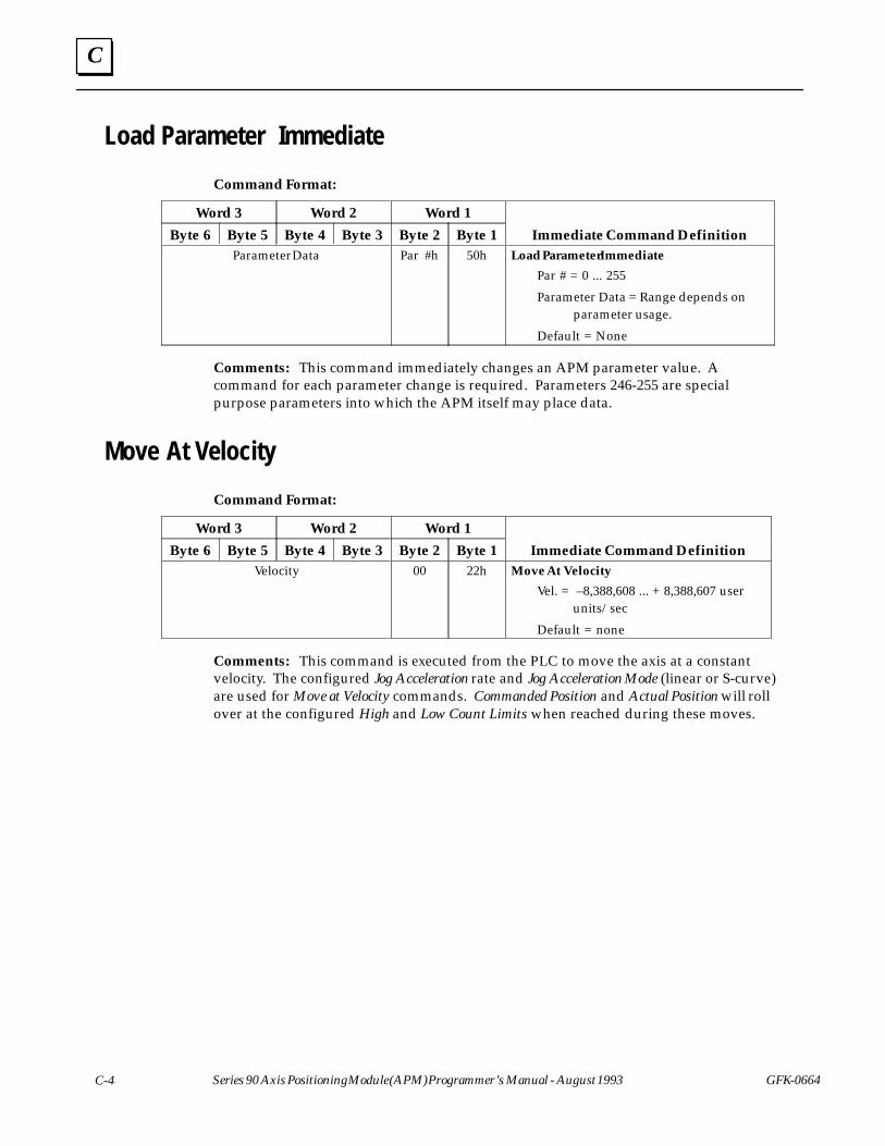
C
C-4 Series 90 Axis Positioning Module (APM) Programmer’s Manual - August 1993 GFK-0664
Load Parameter Immediate
Command Format:ÁÁÁÁÁÁÁÁÁÁÁÁÁÁÁÁÁÁ
Word 3ÁÁÁÁÁÁÁÁÁÁÁÁÁÁÁÁÁÁ
Word 2ÁÁÁÁÁÁÁÁÁÁÁÁÁÁÁÁÁÁ
Word 1ÁÁÁÁÁÁÁÁÁÁÁÁÁÁÁÁÁÁÁÁÁÁÁÁÁÁÁÁÁÁÁÁÁÁÁÁÁÁÁ
ÁÁÁÁÁÁÁÁÁ
Byte 6ÁÁÁÁÁÁÁÁÁÁÁÁ
Byte 5ÁÁÁÁÁÁÁÁÁÁÁÁ
Byte 4ÁÁÁÁÁÁÁÁÁ
Byte 3ÁÁÁÁÁÁÁÁÁÁÁÁ
Byte 2ÁÁÁÁÁÁÁÁÁ
Byte 1ÁÁÁÁÁÁÁÁÁÁÁÁÁÁÁÁÁÁÁÁÁÁÁÁÁÁÁÁÁÁÁÁÁÁÁÁÁÁÁ
Immediate Command DefinitionÁÁÁÁÁÁÁÁÁÁÁÁÁÁÁÁÁÁÁÁÁÁÁÁÁÁÁÁÁÁÁÁÁÁÁÁÁÁÁÁÁÁÁÁÁÁÁÁÁÁÁÁÁÁÁÁÁÁÁÁÁÁÁÁÁÁ
Parameter DataÁÁÁÁÁÁÁÁÁÁÁÁÁÁÁÁÁÁÁÁÁÁÁÁ
Par #hÁÁÁÁÁÁÁÁÁÁÁÁÁÁÁÁÁÁ
50hÁÁÁÁÁÁÁÁÁÁÁÁÁÁÁÁÁÁÁÁÁÁÁÁÁÁÁÁÁÁÁÁÁÁÁÁÁÁÁÁÁÁÁÁÁÁÁÁÁÁÁÁÁÁÁÁÁÁÁÁÁÁÁÁÁÁÁÁÁÁÁÁÁÁÁÁÁÁ
Load Parameter Immediate
Par # = 0 ... 255
Parameter Data = Range depends on parameter usage.
Default = None
Comments: This command immediately changes an APM parameter value. Acommand for each parameter change is required. Parameters 246-255 are specialpurpose parameters into which the APM itself may place data.
Move At Velocity
Command Format:
ÁÁÁÁÁÁÁÁÁÁÁÁ
Word 3 ÁÁÁÁÁÁÁÁÁÁÁÁ
Word 2 ÁÁÁÁÁÁÁÁÁÁÁÁ
Word 1 ÁÁÁÁÁÁÁÁÁÁÁÁÁÁÁÁÁÁÁÁÁÁÁÁÁÁÁÁÁ
ÁÁÁByte 6ÁÁÁÁÁÁÁÁ
Byte 5ÁÁÁÁÁÁÁÁ
Byte 4 ÁÁÁÁÁÁ
Byte 3ÁÁÁÁÁÁÁÁ
Byte 2ÁÁÁÁÁÁ
Byte 1ÁÁÁÁÁÁÁÁÁÁÁÁÁÁÁÁÁÁÁÁÁÁÁÁÁÁ
Immediate Command Definition
ÁÁÁÁÁÁÁÁÁÁÁÁÁÁÁÁÁÁÁÁÁÁÁÁÁÁÁÁÁÁÁÁÁÁÁÁÁÁÁÁÁÁÁÁ
Velocity ÁÁÁÁÁÁÁÁÁÁÁÁÁÁÁÁ
00 ÁÁÁÁÁÁÁÁÁÁÁÁ
22hÁÁÁÁÁÁÁÁÁÁÁÁÁÁÁÁÁÁÁÁÁÁÁÁÁÁÁÁÁÁÁÁÁÁÁÁÁÁÁÁÁÁÁÁÁÁÁÁÁÁÁÁ
Move At Velocity
Vel. = –8,388,608 ... + 8,388,607 user units/sec
Default = none
Comments: This command is executed from the PLC to move the axis at a constantvelocity. The configured Jog Acceleration rate and Jog Acceleration Mode (linear or S-curve)are used for Move at Velocity commands. Commanded Position and Actual Position will rollover at the configured High and Low Count Limits when reached during these moves.
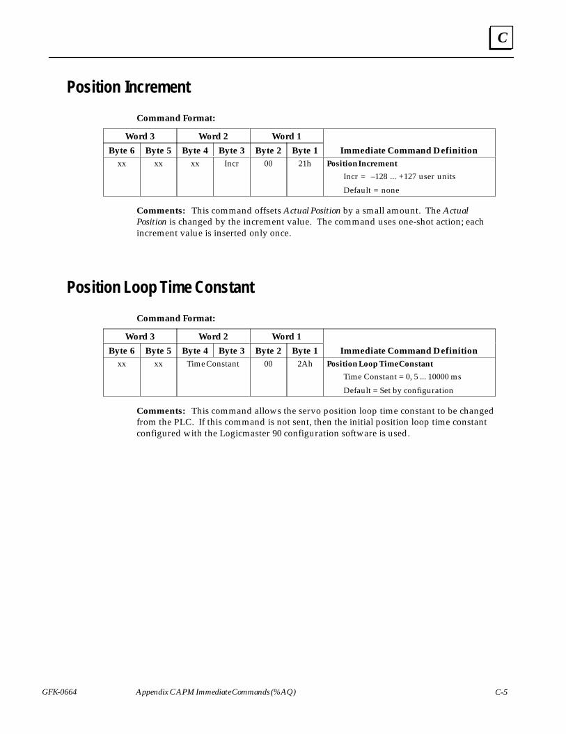
C
GFK-0664 C-5Appendix C APM Immediate Commands (%AQ)
Position Increment
Command Format:ÁÁÁÁÁÁÁÁÁÁÁÁÁÁÁÁÁÁ
Word 3ÁÁÁÁÁÁÁÁÁÁÁÁÁÁÁÁÁÁ
Word 2ÁÁÁÁÁÁÁÁÁÁÁÁÁÁÁÁÁÁ
Word 1ÁÁÁÁÁÁÁÁÁÁÁÁÁÁÁÁÁÁÁÁÁÁÁÁÁÁÁÁÁÁÁÁÁÁÁÁÁÁÁ
ÁÁÁÁÁÁÁÁÁ
Byte 6ÁÁÁÁÁÁÁÁÁÁÁÁ
Byte 5ÁÁÁÁÁÁÁÁÁÁÁÁ
Byte 4ÁÁÁÁÁÁÁÁÁ
Byte 3ÁÁÁÁÁÁÁÁÁÁÁÁ
Byte 2ÁÁÁÁÁÁÁÁÁ
Byte 1ÁÁÁÁÁÁÁÁÁÁÁÁÁÁÁÁÁÁÁÁÁÁÁÁÁÁÁÁÁÁÁÁÁÁÁÁÁÁÁ
Immediate Command DefinitionÁÁÁÁÁÁÁÁÁÁÁÁ
xxÁÁÁÁÁÁÁÁÁÁÁÁÁÁÁÁ
xxÁÁÁÁÁÁÁÁÁÁÁÁÁÁÁÁ
xxÁÁÁÁÁÁÁÁÁÁÁÁ
IncrÁÁÁÁÁÁÁÁÁÁÁÁÁÁÁÁ
00ÁÁÁÁÁÁÁÁÁÁÁÁ
21hÁÁÁÁÁÁÁÁÁÁÁÁÁÁÁÁÁÁÁÁÁÁÁÁÁÁÁÁÁÁÁÁÁÁÁÁÁÁÁÁÁÁÁÁÁÁÁÁÁÁÁÁ
Position Increment
Incr = –128 ... +127 user units
Default = none
Comments: This command offsets Actual Position by a small amount. The ActualPosition is changed by the increment value. The command uses one-shot action; eachincrement value is inserted only once.
Position Loop Time Constant
Command Format:
ÁÁÁÁÁÁÁÁÁÁÁÁ
Word 3 ÁÁÁÁÁÁÁÁÁÁÁÁ
Word 2 ÁÁÁÁÁÁÁÁÁÁÁÁ
Word 1 ÁÁÁÁÁÁÁÁÁÁÁÁÁÁÁÁÁÁÁÁÁÁÁÁÁÁÁÁÁ
ÁÁÁByte 6ÁÁÁÁÁÁÁÁ
Byte 5ÁÁÁÁÁÁÁÁ
Byte 4 ÁÁÁÁÁÁ
Byte 3ÁÁÁÁÁÁÁÁ
Byte 2ÁÁÁÁÁÁ
Byte 1ÁÁÁÁÁÁÁÁÁÁÁÁÁÁÁÁÁÁÁÁÁÁÁÁÁÁ
Immediate Command Definition
ÁÁÁÁÁÁÁÁÁ
xxÁÁÁÁÁÁÁÁÁÁÁÁ
xx ÁÁÁÁÁÁÁÁÁÁÁÁÁÁÁÁÁÁ
Time ConstantÁÁÁÁÁÁÁÁÁÁÁÁ
00 ÁÁÁÁÁÁÁÁÁ
2AhÁÁÁÁÁÁÁÁÁÁÁÁÁÁÁÁÁÁÁÁÁÁÁÁÁÁÁÁÁÁÁÁÁÁÁÁÁÁÁ
Position Loop Time Constant
Time Constant = 0, 5 ... 10000 ms
Default = Set by configuration
Comments: This command allows the servo position loop time constant to be changedfrom the PLC. If this command is not sent, then the initial position loop time constantconfigured with the Logicmaster 90 configuration software is used.

C
C-6 Series 90 Axis Positioning Module (APM) Programmer’s Manual - August 1993 GFK-0664
Rate Override
Command Format:ÁÁÁÁÁÁÁÁÁÁÁÁÁÁÁÁÁÁ
Word 3ÁÁÁÁÁÁÁÁÁÁÁÁÁÁÁÁÁÁ
Word 2ÁÁÁÁÁÁÁÁÁÁÁÁÁÁÁÁÁÁ
Word 1ÁÁÁÁÁÁÁÁÁÁÁÁÁÁÁÁÁÁÁÁÁÁÁÁÁÁÁÁÁÁÁÁÁÁÁÁÁÁÁ
ÁÁÁÁÁÁÁÁÁ
Byte 6ÁÁÁÁÁÁÁÁÁÁÁÁ
Byte 5ÁÁÁÁÁÁÁÁÁÁÁÁ
Byte 4ÁÁÁÁÁÁÁÁÁ
Byte 3ÁÁÁÁÁÁÁÁÁÁÁÁ
Byte 2ÁÁÁÁÁÁÁÁÁ
Byte 1ÁÁÁÁÁÁÁÁÁÁÁÁÁÁÁÁÁÁÁÁÁÁÁÁÁÁÁÁÁÁÁÁÁÁÁÁÁÁÁ
Immediate Command DefinitionÁÁÁÁÁÁÁÁÁÁÁÁ
xxÁÁÁÁÁÁÁÁÁÁÁÁÁÁÁÁ
xxÁÁÁÁÁÁÁÁÁÁÁÁÁÁÁÁ
xxÁÁÁÁÁÁÁÁÁÁÁÁ
RO%ÁÁÁÁÁÁÁÁÁÁÁÁÁÁÁÁ
00ÁÁÁÁÁÁÁÁÁÁÁÁ
20hÁÁÁÁÁÁÁÁÁÁÁÁÁÁÁÁÁÁÁÁÁÁÁÁÁÁÁÁÁÁÁÁÁÁÁÁÁÁÁÁÁÁÁÁÁÁÁÁÁÁÁÁ
Rate Override
RO% = 0 ...120%
Default = none
Comments: This command immediately changes the % feedrate override value(frequently referred to as MFO value). This new value will become effectiveimmediately when received by the APM. It is stored and will remain effective untiloverwritten by a different value.
If sent when the Moving status bit is set, the override change will occur when theCommanded Velocity is constant.
Set Position
Command Format:
ÁÁÁÁÁÁÁÁÁÁÁÁ
Word 3 ÁÁÁÁÁÁÁÁÁÁÁÁ
Word 2 ÁÁÁÁÁÁÁÁÁÁÁÁ
Word 1 ÁÁÁÁÁÁÁÁÁÁÁÁÁÁÁÁÁÁÁÁÁÁÁÁÁÁÁÁÁ
ÁÁÁByte 6ÁÁÁÁÁÁÁÁ
Byte 5ÁÁÁÁÁÁÁÁ
Byte 4 ÁÁÁÁÁÁ
Byte 3ÁÁÁÁÁÁÁÁ
Byte 2ÁÁÁÁÁÁ
Byte 1ÁÁÁÁÁÁÁÁÁÁÁÁÁÁÁÁÁÁÁÁÁÁÁÁÁÁ
Immediate Command DefinitionÁÁÁÁÁÁÁÁÁÁÁÁÁÁÁÁÁÁÁÁÁÁÁÁÁÁÁÁÁÁÁÁÁÁÁÁÁÁÁÁÁÁÁÁ
Position ÁÁÁÁÁÁÁÁÁÁÁÁÁÁÁÁ
00 ÁÁÁÁÁÁÁÁÁÁÁÁ
23hÁÁÁÁÁÁÁÁÁÁÁÁÁÁÁÁÁÁÁÁÁÁÁÁÁÁÁÁÁÁÁÁÁÁÁÁÁÁÁÁÁÁÁÁÁÁÁÁÁÁÁÁ
Set Position
Pos. = –8,388,608 ... + 8,388,607 user units
Default = none
Required Preconditions:
� In Zone set
� Moving cleared
Comments: This command changes the axis position register value without moving theaxis. The Commanded Position and Actual Position values will both be changed so that nomotion command will be generated. The Actual Position will be set to the valuedesignated and the Commanded Position will be set to the value + Position Error.
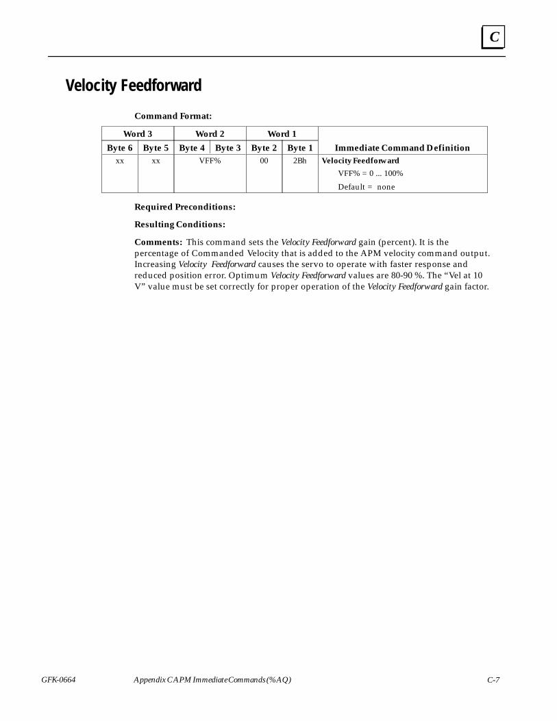
C
GFK-0664 C-7Appendix C APM Immediate Commands (%AQ)
Velocity Feedforward
Command Format:ÁÁÁÁÁÁÁÁÁÁÁÁÁÁÁÁÁÁ
Word 3ÁÁÁÁÁÁÁÁÁÁÁÁÁÁÁÁÁÁ
Word 2ÁÁÁÁÁÁÁÁÁÁÁÁÁÁÁÁÁÁ
Word 1ÁÁÁÁÁÁÁÁÁÁÁÁÁÁÁÁÁÁÁÁÁÁÁÁÁÁÁÁÁÁÁÁÁÁÁÁÁÁÁ
ÁÁÁÁÁÁÁÁÁ
Byte 6ÁÁÁÁÁÁÁÁÁÁÁÁ
Byte 5ÁÁÁÁÁÁÁÁÁÁÁÁ
Byte 4ÁÁÁÁÁÁÁÁÁ
Byte 3ÁÁÁÁÁÁÁÁÁÁÁÁ
Byte 2ÁÁÁÁÁÁÁÁÁ
Byte 1ÁÁÁÁÁÁÁÁÁÁÁÁÁÁÁÁÁÁÁÁÁÁÁÁÁÁÁÁÁÁÁÁÁÁÁÁÁÁÁ
Immediate Command DefinitionÁÁÁÁÁÁÁÁÁÁÁÁ
xxÁÁÁÁÁÁÁÁÁÁÁÁÁÁÁÁ
xxÁÁÁÁÁÁÁÁÁÁÁÁÁÁÁÁÁÁÁÁÁÁÁÁ
VFF%ÁÁÁÁÁÁÁÁÁÁÁÁÁÁÁÁ
00ÁÁÁÁÁÁÁÁÁÁÁÁ
2BhÁÁÁÁÁÁÁÁÁÁÁÁÁÁÁÁÁÁÁÁÁÁÁÁÁÁÁÁÁÁÁÁÁÁÁÁÁÁÁÁÁÁÁÁÁÁÁÁÁÁÁÁ
Velocity Feedforward
VFF% = 0 ... 100%
Default = none
Required Preconditions:
Resulting Conditions:
Comments: This command sets the Velocity Feedforward gain (percent). It is thepercentage of Commanded Velocity that is added to the APM velocity command output.Increasing Velocity Feedforward causes the servo to operate with faster response andreduced position error. Optimum Velocity Feedforward values are 80-90 %. The “Vel at 10V” value must be set correctly for proper operation of the Velocity Feedforward gain factor.
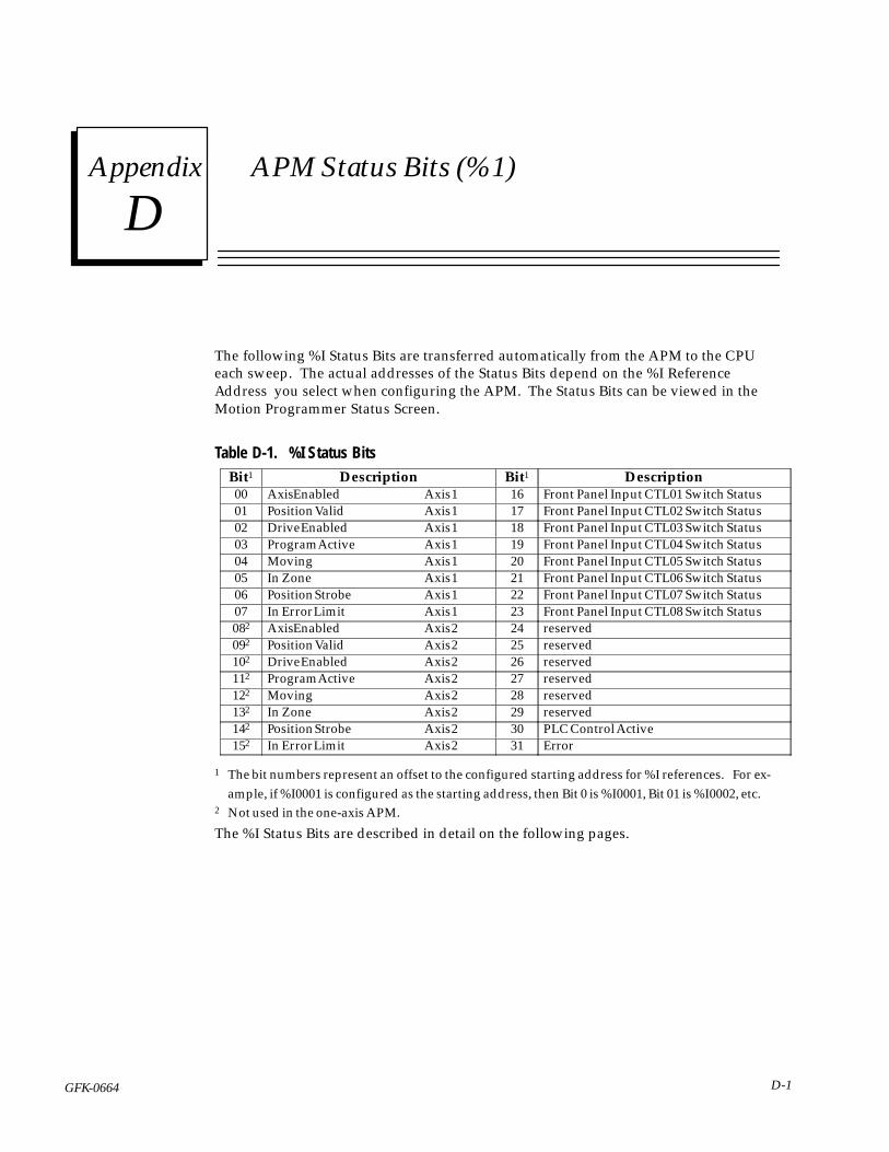
Dsection level 1 1figure_ap level 1 table_ap level 1
D-1GFK-0664
Appendix D APM Status Bits (%1)
The following %I Status Bits are transferred automatically from the APM to the CPUeach sweep. The actual addresses of the Status Bits depend on the %I ReferenceAddress you select when configuring the APM. The Status Bits can be viewed in theMotion Programmer Status Screen.
Table D-1. %I Status BitsÁÁÁÁÁÁBit1
ÁÁÁÁÁÁÁÁÁÁÁÁÁÁÁÁÁÁÁÁÁÁÁÁDescription
ÁÁÁÁÁÁBit1
ÁÁÁÁÁÁÁÁÁÁÁÁÁÁÁÁÁÁÁÁÁÁÁÁDescriptionÁÁÁ
ÁÁÁ00ÁÁÁÁÁÁÁÁÁÁÁÁÁÁÁÁÁÁÁÁÁÁÁÁ
Axis Enabled Axis 1 ÁÁÁÁÁÁ
16 ÁÁÁÁÁÁÁÁÁÁÁÁÁÁÁÁÁÁÁÁÁÁÁÁ
Front Panel Input CTL01 Switch StatusÁÁÁÁÁÁ
01ÁÁÁÁÁÁÁÁÁÁÁÁÁÁÁÁÁÁÁÁÁÁÁÁ
Position Valid Axis 1 ÁÁÁÁÁÁ
17 ÁÁÁÁÁÁÁÁÁÁÁÁÁÁÁÁÁÁÁÁÁÁÁÁ
Front Panel Input CTL02 Switch Status
ÁÁÁÁÁÁ
02ÁÁÁÁÁÁÁÁÁÁÁÁÁÁÁÁÁÁÁÁÁÁÁÁ
Drive Enabled Axis 1 ÁÁÁÁÁÁ
18 ÁÁÁÁÁÁÁÁÁÁÁÁÁÁÁÁÁÁÁÁÁÁÁÁ
Front Panel Input CTL03 Switch StatusÁÁÁÁÁÁ03
ÁÁÁÁÁÁÁÁÁÁÁÁÁÁÁÁÁÁÁÁÁÁÁÁProgram Active Axis 1
ÁÁÁÁÁÁ19
ÁÁÁÁÁÁÁÁÁÁÁÁÁÁÁÁÁÁÁÁÁÁÁÁFront Panel Input CTL04 Switch StatusÁÁÁ
ÁÁÁ04ÁÁÁÁÁÁÁÁÁÁÁÁÁÁÁÁÁÁÁÁÁÁÁÁ
Moving Axis 1 ÁÁÁÁÁÁ
20 ÁÁÁÁÁÁÁÁÁÁÁÁÁÁÁÁÁÁÁÁÁÁÁÁ
Front Panel Input CTL05 Switch StatusÁÁÁÁÁÁ
05ÁÁÁÁÁÁÁÁÁÁÁÁÁÁÁÁÁÁÁÁÁÁÁÁ
In Zone Axis 1 ÁÁÁÁÁÁ
21 ÁÁÁÁÁÁÁÁÁÁÁÁÁÁÁÁÁÁÁÁÁÁÁÁ
Front Panel Input CTL06 Switch Status
ÁÁÁÁÁÁ
06ÁÁÁÁÁÁÁÁÁÁÁÁÁÁÁÁÁÁÁÁÁÁÁÁ
Position Strobe Axis 1 ÁÁÁÁÁÁ
22 ÁÁÁÁÁÁÁÁÁÁÁÁÁÁÁÁÁÁÁÁÁÁÁÁ
Front Panel Input CTL07 Switch StatusÁÁÁÁÁÁ07
ÁÁÁÁÁÁÁÁÁÁÁÁÁÁÁÁÁÁÁÁÁÁÁÁIn Error Limit Axis 1
ÁÁÁÁÁÁ23
ÁÁÁÁÁÁÁÁÁÁÁÁÁÁÁÁÁÁÁÁÁÁÁÁFront Panel Input CTL08 Switch StatusÁÁÁ
ÁÁÁ082ÁÁÁÁÁÁÁÁÁÁÁÁÁÁÁÁÁÁÁÁÁÁÁÁ
Axis Enabled Axis 2 ÁÁÁÁÁÁ
24 ÁÁÁÁÁÁÁÁÁÁÁÁÁÁÁÁÁÁÁÁÁÁÁÁ
reservedÁÁÁÁÁÁ
092ÁÁÁÁÁÁÁÁÁÁÁÁÁÁÁÁÁÁÁÁÁÁÁÁ
Position Valid Axis 2 ÁÁÁÁÁÁ
25 ÁÁÁÁÁÁÁÁÁÁÁÁÁÁÁÁÁÁÁÁÁÁÁÁ
reserved
ÁÁÁÁÁÁ
102ÁÁÁÁÁÁÁÁÁÁÁÁÁÁÁÁÁÁÁÁÁÁÁÁ
Drive Enabled Axis 2 ÁÁÁÁÁÁ
26 ÁÁÁÁÁÁÁÁÁÁÁÁÁÁÁÁÁÁÁÁÁÁÁÁ
reservedÁÁÁÁÁÁ112
ÁÁÁÁÁÁÁÁÁÁÁÁÁÁÁÁÁÁÁÁÁÁÁÁProgram Active Axis 2
ÁÁÁÁÁÁ27
ÁÁÁÁÁÁÁÁÁÁÁÁÁÁÁÁÁÁÁÁÁÁÁÁreservedÁÁÁ
ÁÁÁ122ÁÁÁÁÁÁÁÁÁÁÁÁÁÁÁÁÁÁÁÁÁÁÁÁ
Moving Axis 2 ÁÁÁÁÁÁ
28 ÁÁÁÁÁÁÁÁÁÁÁÁÁÁÁÁÁÁÁÁÁÁÁÁ
reservedÁÁÁÁÁÁ
132ÁÁÁÁÁÁÁÁÁÁÁÁÁÁÁÁÁÁÁÁÁÁÁÁ
In Zone Axis 2 ÁÁÁÁÁÁ
29 ÁÁÁÁÁÁÁÁÁÁÁÁÁÁÁÁÁÁÁÁÁÁÁÁ
reserved
ÁÁÁÁÁÁ
142ÁÁÁÁÁÁÁÁÁÁÁÁÁÁÁÁÁÁÁÁÁÁÁÁ
Position Strobe Axis 2 ÁÁÁÁÁÁ
30 ÁÁÁÁÁÁÁÁÁÁÁÁÁÁÁÁÁÁÁÁÁÁÁÁ
PLC Control ActiveÁÁÁÁÁÁ152
ÁÁÁÁÁÁÁÁÁÁÁÁÁÁÁÁÁÁÁÁÁÁÁÁIn Error Limit Axis 2
ÁÁÁÁÁÁ31
ÁÁÁÁÁÁÁÁÁÁÁÁÁÁÁÁÁÁÁÁÁÁÁÁError
1 The bit numbers represent an offset to the configured starting address for %I references. For ex-ample, if %I0001 is configured as the starting address, then Bit 0 is %I0001, Bit 01 is %I0002, etc.
2 Not used in the one-axis APM.
The %I Status Bits are described in detail on the following pages.
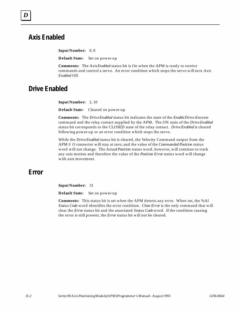
D
D-2 Series 90 Axis Positioning Module (APM) Programmer’s Manual - August 1993 GFK-0664
Axis Enabled
Input Number: 0, 8
Default State: Set on power-up
Comments: The Axis Enabled status bit is On when the APM is ready to receivecommands and control a servo. An error condition which stops the servo will turn AxisEnabled Off.
Drive Enabled
Input Number: 2, 10
Default State: Cleared on power-up
Comments: The Drive Enabled status bit indicates the state of the Enable Drive discretecommand and the relay contact supplied by the APM. The ON state of the Drive Enabledstatus bit corresponds to the CLOSED state of the relay contact. Drive Enabled is clearedfollowing power-up or an error condition which stops the servo.
While the Drive Enabled status bit is cleared, the Velocity Command output from theAPM I/O connector will stay at zero, and the value of the Commanded Position statusword will not change. The Actual Position status word, however, will continue to trackany axis motion and therefore the value of the Position Error status word will changewith axis movement.
Error
Input Number: 31
Default State: Set on power-up
Comments: This status bit is set when the APM detects any error. When set, the %AIStatus Code word identifies the error condition. Clear Error is the only command that willclear the Error status bit and the associated Status Code word. If the condition causingthe error is still present, the Error status bit will not be cleared.

D
GFK-0664 D-3Appendix D APM Status Bits (%1)
Faceplate Input Status CTL 01-08
Input Number: 16-23
Default State: None
Comments: These inputs always indicate the state of the external input devicesconnected to the APM faceplate terminals CTL01-08. These inputs (as well asCTL09-CTL12 from the PLC %Q table) may be tested by the APM during the executionof Wait and Conditional Jump commands.
Several inputs may serve alternate purposes:
CTL01 - Axis 1 Strobe input CTL02 - Axis 2 Strobe inputCTL03 - Axis 1 Home switch input CTL04 - Axis 2 Home switch inputCTL05 - Axis 1 Overtravel (+) switch input CTL07 - Axis 2 Overtravel (+) switch inputCTL06 - Axis 1 Overtravel (–) switch input CTL08 - Axis 2 Overtravel (–) switch input
In Error Limit
Input Number: 5, 13
Default State: Cleared on Power-up and following a Drive Enable command
Comments: The In Error Limit status bit is set when the absolute value of the positionerror exceeds the configured Position Error Limit value. When the In Error Limit status bitis set, commanded velocity and commanded position are frozen to allow the axis to“catch up” to the commanded position.
The In Error Limit status bit could be set for any of the following reasons:
1. Configured value for Position Error Limit is too low for the configured value of Posi-tion Loop Time Constant.
2. The maximum servo drive velocity (produced by a 10 V Velocity Command) is lowerthan the programmed velocity.
3. The servo drive is incapable of following the programmed velocity and/or acceleration.
4. Feedback signals have been lost or corrupted.
Some applications may intentionally run in error limit to make use of its commandvelocity limiting feature, but unless it is expected, once a system has been “tuned” itshould not occur for normal operation.

D
D-4 Series 90 Axis Positioning Module (APM) Programmer’s Manual - August 1993 GFK-0664
In Zone
Input Number: 5, 13
Default State: None
Comments: The In Zone status bit indicates that the position error is equal to or lessthan the configured In Position Zone value. This condition occurs at the end of eachPositioning Move command or any time the axis commands are halted and the actualposition has caught up to the commanded position (e.g. for Dwell and Feedhold).
Moving
Input Number: 7, 15
Default State: Cleared on power-up.
Comments: The Moving status bit is set when commanded velocity is non-zero,otherwise it is cleared. All Positioning Move, Continuous Move, Jog, and Move at Velocitycommands will cause the Moving bit to be set. The Force D/A Output command will notset the Moving bit. Moving remains ON when MFO is 0%.
PLC Control Active
Input Number: 30
Default State: Set on power-up
Comments: Normally the PLC Control Active status bit is set, indicating that the %Qdiscrete commands or %AQ immediate commands from the PLC are controlling theAPM.
When the Logicmaster 90 Motion Programmer requests control of the APM via itsControl/Status screen, the PLC Control Active bit will be cleared. The APM will ignore thePLC %Q discrete and %AQ immediate commands and respond only to the %Q and%AQ commands from the Motion Programmer. If the Motion Programmer losescommunications with the APM while the Control/Status screen is controlling the APM,then the APM will enter the Disable state. The PLC Control Active bit will remain clearedunless the Motion Programmer re-establishes communications and the user requeststhat control be switched back to the PLC.
Note
In this release of the Motion Programmer software, the Control/Statusscreen performs only Status functions. The PLC Control Active status bitis always 1.
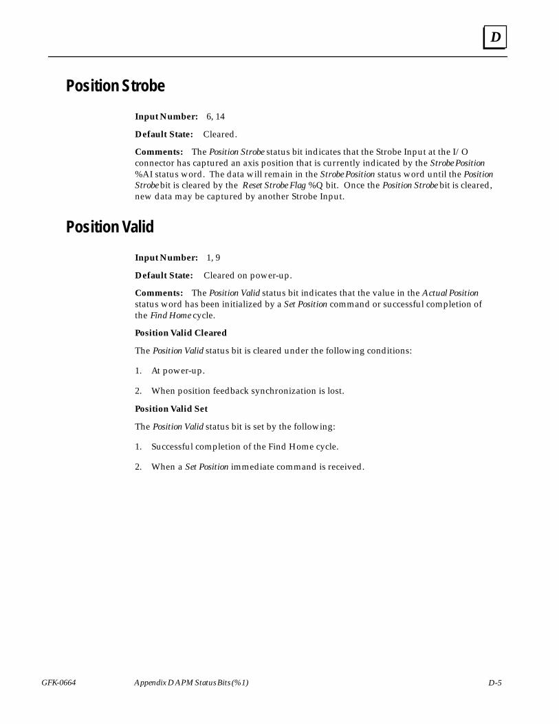
D
GFK-0664 D-5Appendix D APM Status Bits (%1)
Position Strobe
Input Number: 6, 14
Default State: Cleared.
Comments: The Position Strobe status bit indicates that the Strobe Input at the I/Oconnector has captured an axis position that is currently indicated by the Strobe Position%AI status word. The data will remain in the Strobe Position status word until the PositionStrobe bit is cleared by the Reset Strobe Flag %Q bit. Once the Position Strobe bit is cleared,new data may be captured by another Strobe Input.
Position Valid
Input Number: 1, 9
Default State: Cleared on power-up.
Comments: The Position Valid status bit indicates that the value in the Actual Positionstatus word has been initialized by a Set Position command or successful completion ofthe Find Home cycle.
Position Valid Cleared
The Position Valid status bit is cleared under the following conditions:
1. At power-up.
2. When position feedback synchronization is lost.
Position Valid Set
The Position Valid status bit is set by the following:
1. Successful completion of the Find Home cycle.
2. When a Set Position immediate command is received.
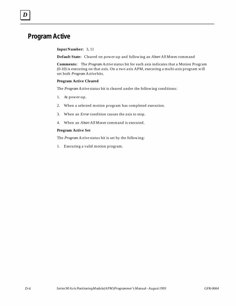
D
D-6 Series 90 Axis Positioning Module (APM) Programmer’s Manual - August 1993 GFK-0664
Program Active
Input Number: 3, 11
Default State: Cleared on power-up and following an Abort All Moves command
Comments: The Program Active status bit for each axis indicates that a Motion Program(0-10) is executing on that axis. On a two axis APM, executing a multi-axis program willset both Program Active bits.
Program Active Cleared
The Program Active status bit is cleared under the following conditions:
1. At power-up.
2. When a selected motion program has completed execution.
3. When an Error condition causes the axis to stop.
4. When an Abort All Moves command is executed.
Program Active Set
The Program Active status bit is set by the following:
1. Executing a valid motion program.
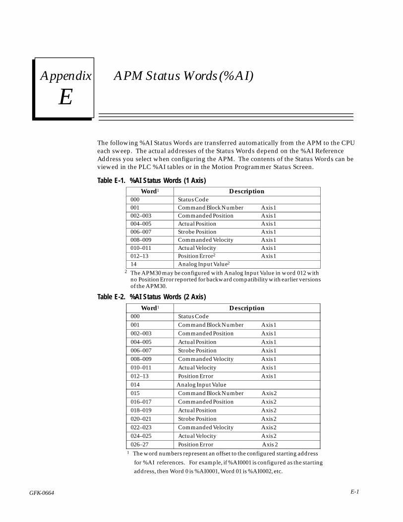
Esection level 1 1figure_ap level 1 table_ap level 1
E-1GFK-0664
Appendix E APM Status Words (%AI)
The following %AI Status Words are transferred automatically from the APM to the CPUeach sweep. The actual addresses of the Status Words depend on the %AI ReferenceAddress you select when configuring the APM. The contents of the Status Words can beviewed in the PLC %AI tables or in the Motion Programmer Status Screen.
Table E-1. %AI Status Words (1 Axis)ÁÁÁÁÁÁÁÁÁÁÁÁ
Word1 ÁÁÁÁÁÁÁÁÁÁÁÁÁÁÁÁÁÁÁÁÁÁÁÁÁÁÁÁÁÁ
DescriptionÁÁÁÁÁÁÁÁÁÁÁÁ
000 ÁÁÁÁÁÁÁÁÁÁÁÁÁÁÁÁÁÁÁÁÁÁÁÁÁÁÁÁÁÁ
Status Code
ÁÁÁÁÁÁ001 ÁÁÁÁÁÁÁÁÁÁÁÁÁÁÁCommand Block Number Axis 1ÁÁÁÁÁÁÁÁÁÁÁÁ002–003
ÁÁÁÁÁÁÁÁÁÁÁÁÁÁÁÁÁÁÁÁÁÁÁÁÁÁÁÁÁÁCommanded Position Axis 1
ÁÁÁÁÁÁÁÁÁÁÁÁ
004–005 ÁÁÁÁÁÁÁÁÁÁÁÁÁÁÁÁÁÁÁÁÁÁÁÁÁÁÁÁÁÁ
Actual Position Axis 1ÁÁÁÁÁÁÁÁÁÁÁÁ
006–007 ÁÁÁÁÁÁÁÁÁÁÁÁÁÁÁÁÁÁÁÁÁÁÁÁÁÁÁÁÁÁ
Strobe Position Axis 1
ÁÁÁÁÁÁÁÁÁÁÁÁ
008–009 ÁÁÁÁÁÁÁÁÁÁÁÁÁÁÁÁÁÁÁÁÁÁÁÁÁÁÁÁÁÁ
Commanded Velocity Axis 1
ÁÁÁÁÁÁ010–011 ÁÁÁÁÁÁÁÁÁÁÁÁÁÁÁActual Velocity Axis 1ÁÁÁÁÁÁÁÁÁÁÁÁ
012–13ÁÁÁÁÁÁÁÁÁÁÁÁÁÁÁÁÁÁÁÁÁÁÁÁÁÁÁÁÁÁ
Position Error2 Axis 1ÁÁÁÁÁÁÁÁÁÁÁÁ
14 ÁÁÁÁÁÁÁÁÁÁÁÁÁÁÁÁÁÁÁÁÁÁÁÁÁÁÁÁÁÁ
Analog Input Value2
2 The APM30 may be configured with Analog Input Value in word 012 with no Position Error reported for backward compatibility with earlier versionsof the APM30.
Table E-2. %AI Status Words (2 Axis)ÁÁÁÁÁÁÁÁÁÁÁÁWord1
ÁÁÁÁÁÁÁÁÁÁÁÁÁÁÁÁÁÁÁÁÁÁÁÁÁÁÁÁÁÁDescriptionÁÁÁÁÁÁ
ÁÁÁÁÁÁ000
ÁÁÁÁÁÁÁÁÁÁÁÁÁÁÁÁÁÁÁÁÁÁÁÁÁÁÁÁÁÁ
Status CodeÁÁÁÁÁÁÁÁÁÁÁÁ
001 ÁÁÁÁÁÁÁÁÁÁÁÁÁÁÁÁÁÁÁÁÁÁÁÁÁÁÁÁÁÁ
Command Block Number Axis 1ÁÁÁÁÁÁÁÁÁÁÁÁ
002–003 ÁÁÁÁÁÁÁÁÁÁÁÁÁÁÁÁÁÁÁÁÁÁÁÁÁÁÁÁÁÁ
Commanded Position Axis 1ÁÁÁÁÁÁÁÁÁÁÁÁ
004–005 ÁÁÁÁÁÁÁÁÁÁÁÁÁÁÁÁÁÁÁÁÁÁÁÁÁÁÁÁÁÁ
Actual Position Axis 1
ÁÁÁÁÁÁÁÁÁÁÁÁ
006–007 ÁÁÁÁÁÁÁÁÁÁÁÁÁÁÁÁÁÁÁÁÁÁÁÁÁÁÁÁÁÁ
Strobe Position Axis 1ÁÁÁÁÁÁÁÁÁÁÁÁ008–009
ÁÁÁÁÁÁÁÁÁÁÁÁÁÁÁÁÁÁÁÁÁÁÁÁÁÁÁÁÁÁCommanded Velocity Axis 1ÁÁÁÁÁÁ
ÁÁÁÁÁÁ010–011ÁÁÁÁÁÁÁÁÁÁÁÁÁÁÁÁÁÁÁÁÁÁÁÁÁÁÁÁÁÁActual Velocity Axis 1ÁÁÁÁÁÁ
ÁÁÁÁÁÁ012–13 ÁÁÁÁÁÁÁÁÁÁÁÁÁÁÁ
ÁÁÁÁÁÁÁÁÁÁÁÁÁÁÁPosition Error Axis 1
ÁÁÁÁÁÁÁÁÁÁÁÁ
014 ÁÁÁÁÁÁÁÁÁÁÁÁÁÁÁÁÁÁÁÁÁÁÁÁÁÁÁÁÁÁ
Analog Input ValueÁÁÁÁÁÁÁÁÁÁÁÁ
015 ÁÁÁÁÁÁÁÁÁÁÁÁÁÁÁÁÁÁÁÁÁÁÁÁÁÁÁÁÁÁ
Command Block Number Axis 2
ÁÁÁÁÁÁÁÁÁÁÁÁ
016–017 ÁÁÁÁÁÁÁÁÁÁÁÁÁÁÁÁÁÁÁÁÁÁÁÁÁÁÁÁÁÁ
Commanded Position Axis 2
ÁÁÁÁÁÁ018–019 ÁÁÁÁÁÁÁÁÁÁÁÁÁÁÁActual Position Axis 2ÁÁÁÁÁÁÁÁÁÁÁÁ020–021
ÁÁÁÁÁÁÁÁÁÁÁÁÁÁÁÁÁÁÁÁÁÁÁÁÁÁÁÁÁÁStrobe Position Axis 2ÁÁÁÁÁÁ
ÁÁÁÁÁÁ022–023
ÁÁÁÁÁÁÁÁÁÁÁÁÁÁÁÁÁÁÁÁÁÁÁÁÁÁÁÁÁÁ
Commanded Velocity Axis 2ÁÁÁÁÁÁÁÁÁÁÁÁ
024–025 ÁÁÁÁÁÁÁÁÁÁÁÁÁÁÁÁÁÁÁÁÁÁÁÁÁÁÁÁÁÁ
Actual Velocity Axis 2ÁÁÁÁÁÁÁÁÁÁÁÁ
026–27 ÁÁÁÁÁÁÁÁÁÁÁÁÁÁÁÁÁÁÁÁÁÁÁÁÁÁÁÁÁÁ
Position Error Axis 21 The word numbers represent an offset to the configured starting address
for %AI references. For example, if %AI0001 is configured as the starting address, then Word 0 is %AI0001, Word 01 is %AI0002, etc.
E
E-2 Series 90 Axis Positioning Module (APM) Programmer’s Manual - August 1993 GFK-0664
The %AI Status Words are described in detail on the following pages.
Actual PositionActual Position (user units) is a value maintained by the APM30 to represent the physicalposition of the axis. It is set to an initial value by the Set Position command or to HomePosition by the Find Home cycle. It is updated by the motion of the feedback device.
If Actual Position is counted past either of its limits, it will “rollover” to the other limit andcontinue counting in the direction of the axis motion.
Actual Velocity Actual Velocity (user units/sec) is a value maintained by the APM30 that is derived fromthe input counts of the feedback device. Therefore, it represents the instantaneousvelocity of the axis movement.
Analog InputAnalog Input returns the digital value representing the voltage applied to the analoginput terminal. +10 V is indicated by +32,000 and –10 V by –32,000.
Command Block NumberCommand Block Number indicates the block number of the command that is presentlybeing executed in the active Program or Subroutine. It changes at the start of each newblock as the program commands are executed, and thus identifies the present operatinglocation within the program.
Commanded PositionCommanded Position (user units) is where the axis is commanded to be at any instant intime. The difference between Commanded Position and Actual Position is a positionerror value which produces the Velocity Command to drive the axis. The rate at whichthe Command Position is incremented (or decremented) determines the velocity of axismotion.
Commanded VelocityCommanded Velocity (user units) is a value generated by the APM30 that indicates theinstantaneous velocity command that is producing axis motion. At the beginning of amove it will increase at the acceleration rate, and once the programmed velocity hasbeen reached, it will stabilize at the programmed velocity value.
Position ErrorPosition Error (user units) is equal to Commanded Position – Actual Position.
Status CodeStatus Code indicates the current operating status of the module. When the Error statusbit is set, it contains the offending error code number.
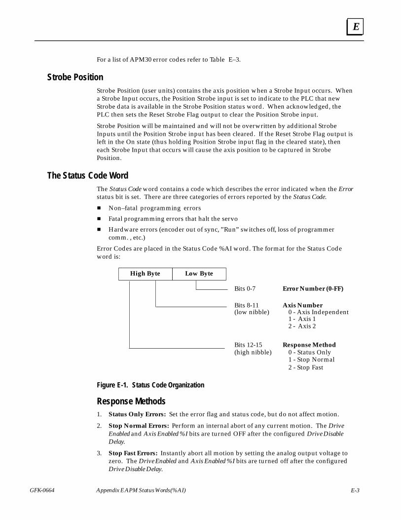
E
GFK-0664 E-3Appendix E APM Status Words (%AI)
For a list of APM30 error codes refer to Table E–3.
Strobe PositionStrobe Position (user units) contains the axis position when a Strobe Input occurs. Whena Strobe Input occurs, the Position Strobe input is set to indicate to the PLC that newStrobe data is available in the Strobe Position status word. When acknowledged, thePLC then sets the Reset Strobe Flag output to clear the Position Strobe input.
Strobe Position will be maintained and will not be overwritten by additional StrobeInputs until the Position Strobe input has been cleared. If the Reset Strobe Flag output isleft in the On state (thus holding Position Strobe input flag in the cleared state), theneach Strobe Input that occurs will cause the axis position to be captured in StrobePosition.
The Status Code WordThe Status Code word contains a code which describes the error indicated when the Errorstatus bit is set. There are three categories of errors reported by the Status Code.
� Non–fatal programming errors
� Fatal programming errors that halt the servo
� Hardware errors (encoder out of sync, ”Run” switches off, loss of programmercomm. , etc.)
Error Codes are placed in the Status Code %AI word. The format for the Status Codeword is:
High Byte Low Byte
Bits 0-7 Error Number (0-FF)
Bits 8-11 Axis Number
1 - Axis 12 - Axis 2
Response MethodBits 12-15(high nibble) 0 - Status Only
1 - Stop Normal2 - Stop Fast
0 - Axis Independent(low nibble)
Figure E-1. Status Code Organization
Response Methods1. Status Only Errors: Set the error flag and status code, but do not affect motion.
2. Stop Normal Errors: Perform an internal abort of any current motion. The DriveEnabled and Axis Enabled %I bits are turned OFF after the configured Drive DisableDelay.
3. Stop Fast Errors: Instantly abort all motion by setting the analog output voltage tozero. The Drive Enabled and Axis Enabled %I bits are turned off after the configuredDrive Disable Delay.
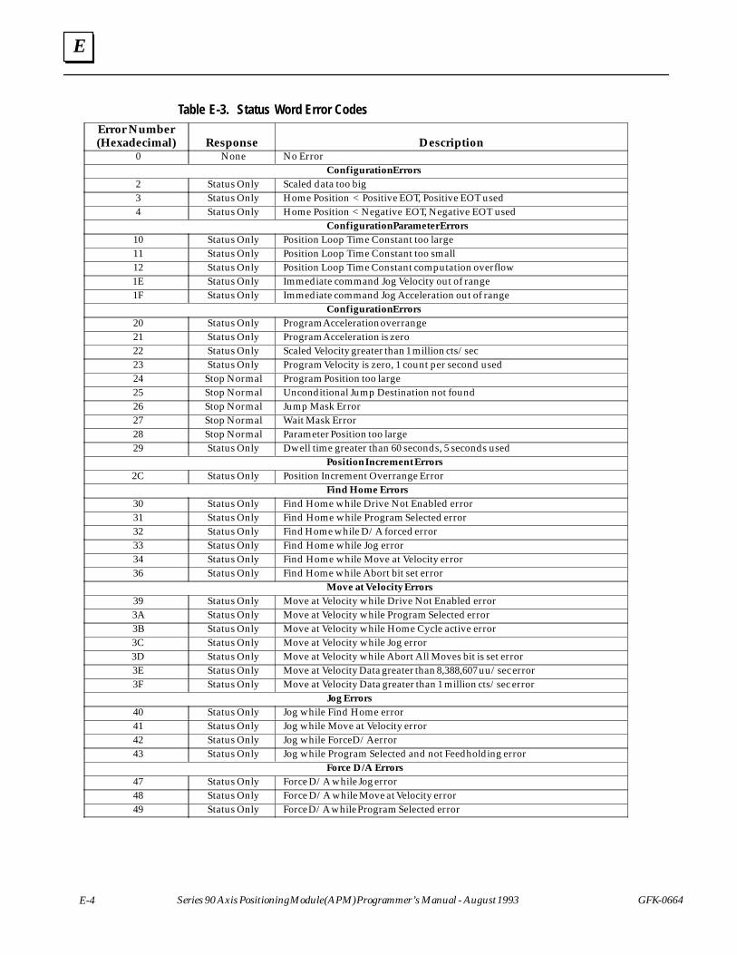
E
E-4 Series 90 Axis Positioning Module (APM) Programmer’s Manual - August 1993 GFK-0664
Table E-3. Status Word Error CodesÁÁÁÁÁÁÁÁÁÁÁÁÁÁÁÁÁÁÁÁÁ
Error Number(Hexadecimal)
ÁÁÁÁÁÁÁÁÁÁÁÁÁÁÁ
ResponseÁÁÁÁÁÁÁÁÁÁÁÁÁÁÁÁÁÁÁÁÁÁÁÁÁÁÁÁÁÁÁÁÁÁÁÁÁÁÁÁÁÁÁÁÁÁÁÁÁÁÁÁÁÁÁÁÁÁÁÁ
Description
ÁÁÁÁÁÁÁ0 ÁÁÁÁÁNone ÁÁÁÁÁÁÁÁÁÁÁÁÁÁÁÁÁÁÁÁNo ErrorÁÁÁÁÁÁÁÁÁÁÁÁÁÁ
ÁÁÁÁÁÁÁÁÁÁ
ÁÁÁÁÁÁÁÁÁÁÁÁÁÁÁÁÁÁÁÁÁÁÁÁÁÁÁÁÁÁÁÁÁÁÁÁÁÁÁÁ
Configuration ErrorsÁÁÁÁÁÁÁÁÁÁÁÁÁÁ
2 ÁÁÁÁÁÁÁÁÁÁ
Status OnlyÁÁÁÁÁÁÁÁÁÁÁÁÁÁÁÁÁÁÁÁÁÁÁÁÁÁÁÁÁÁÁÁÁÁÁÁÁÁÁÁ
Scaled data too big
ÁÁÁÁÁÁÁÁÁÁÁÁÁÁ
3 ÁÁÁÁÁÁÁÁÁÁ
Status OnlyÁÁÁÁÁÁÁÁÁÁÁÁÁÁÁÁÁÁÁÁÁÁÁÁÁÁÁÁÁÁÁÁÁÁÁÁÁÁÁÁ
Home Position < Positive EOT, Positive EOT used
ÁÁÁÁÁÁÁ4 ÁÁÁÁÁStatus OnlyÁÁÁÁÁÁÁÁÁÁÁÁÁÁÁÁÁÁÁÁHome Position < Negative EOT, Negative EOT usedÁÁÁÁÁÁÁÁÁÁÁÁÁÁ
ÁÁÁÁÁÁÁÁÁÁ
ÁÁÁÁÁÁÁÁÁÁÁÁÁÁÁÁÁÁÁÁÁÁÁÁÁÁÁÁÁÁÁÁÁÁÁÁÁÁÁÁ
Configuration Parameter ErrorsÁÁÁÁÁÁÁÁÁÁÁÁÁÁ
10 ÁÁÁÁÁÁÁÁÁÁ
Status OnlyÁÁÁÁÁÁÁÁÁÁÁÁÁÁÁÁÁÁÁÁÁÁÁÁÁÁÁÁÁÁÁÁÁÁÁÁÁÁÁÁ
Position Loop Time Constant too large
ÁÁÁÁÁÁÁÁÁÁÁÁÁÁ
11 ÁÁÁÁÁÁÁÁÁÁ
Status OnlyÁÁÁÁÁÁÁÁÁÁÁÁÁÁÁÁÁÁÁÁÁÁÁÁÁÁÁÁÁÁÁÁÁÁÁÁÁÁÁÁ
Position Loop Time Constant too small
ÁÁÁÁÁÁÁ12 ÁÁÁÁÁStatus OnlyÁÁÁÁÁÁÁÁÁÁÁÁÁÁÁÁÁÁÁÁPosition Loop Time Constant computation overflowÁÁÁÁÁÁÁÁÁÁÁÁÁÁ
1EÁÁÁÁÁÁÁÁÁÁ
Status OnlyÁÁÁÁÁÁÁÁÁÁÁÁÁÁÁÁÁÁÁÁÁÁÁÁÁÁÁÁÁÁÁÁÁÁÁÁÁÁÁÁ
Immediate command Jog Velocity out of rangeÁÁÁÁÁÁÁÁÁÁÁÁÁÁ
1F ÁÁÁÁÁÁÁÁÁÁ
Status OnlyÁÁÁÁÁÁÁÁÁÁÁÁÁÁÁÁÁÁÁÁÁÁÁÁÁÁÁÁÁÁÁÁÁÁÁÁÁÁÁÁ
Immediate command Jog Acceleration out of range
ÁÁÁÁÁÁÁÁÁÁÁÁÁÁ
ÁÁÁÁÁÁÁÁÁÁ
ÁÁÁÁÁÁÁÁÁÁÁÁÁÁÁÁÁÁÁÁÁÁÁÁÁÁÁÁÁÁÁÁÁÁÁÁÁÁÁÁ
Configuration Errors
ÁÁÁÁÁÁÁ20 ÁÁÁÁÁStatus OnlyÁÁÁÁÁÁÁÁÁÁÁÁÁÁÁÁÁÁÁÁProgram Acceleration overrangeÁÁÁÁÁÁÁÁÁÁÁÁÁÁ
21ÁÁÁÁÁÁÁÁÁÁ
Status OnlyÁÁÁÁÁÁÁÁÁÁÁÁÁÁÁÁÁÁÁÁÁÁÁÁÁÁÁÁÁÁÁÁÁÁÁÁÁÁÁÁ
Program Acceleration is zeroÁÁÁÁÁÁÁÁÁÁÁÁÁÁ
22 ÁÁÁÁÁÁÁÁÁÁ
Status OnlyÁÁÁÁÁÁÁÁÁÁÁÁÁÁÁÁÁÁÁÁÁÁÁÁÁÁÁÁÁÁÁÁÁÁÁÁÁÁÁÁ
Scaled Velocity greater than 1 million cts/sec
ÁÁÁÁÁÁÁÁÁÁÁÁÁÁ
23 ÁÁÁÁÁÁÁÁÁÁ
Status OnlyÁÁÁÁÁÁÁÁÁÁÁÁÁÁÁÁÁÁÁÁÁÁÁÁÁÁÁÁÁÁÁÁÁÁÁÁÁÁÁÁ
Program Velocity is zero, 1 count per second used
ÁÁÁÁÁÁÁ24 ÁÁÁÁÁStop NormalÁÁÁÁÁÁÁÁÁÁÁÁÁÁÁÁÁÁÁÁProgram Position too largeÁÁÁÁÁÁÁÁÁÁÁÁÁÁ
25ÁÁÁÁÁÁÁÁÁÁ
Stop NormalÁÁÁÁÁÁÁÁÁÁÁÁÁÁÁÁÁÁÁÁÁÁÁÁÁÁÁÁÁÁÁÁÁÁÁÁÁÁÁÁ
Unconditional Jump Destination not foundÁÁÁÁÁÁÁÁÁÁÁÁÁÁ
26 ÁÁÁÁÁÁÁÁÁÁ
Stop NormalÁÁÁÁÁÁÁÁÁÁÁÁÁÁÁÁÁÁÁÁÁÁÁÁÁÁÁÁÁÁÁÁÁÁÁÁÁÁÁÁ
Jump Mask Error
ÁÁÁÁÁÁÁÁÁÁÁÁÁÁ
27 ÁÁÁÁÁÁÁÁÁÁ
Stop NormalÁÁÁÁÁÁÁÁÁÁÁÁÁÁÁÁÁÁÁÁÁÁÁÁÁÁÁÁÁÁÁÁÁÁÁÁÁÁÁÁ
Wait Mask Error
ÁÁÁÁÁÁÁ28 ÁÁÁÁÁStop NormalÁÁÁÁÁÁÁÁÁÁÁÁÁÁÁÁÁÁÁÁParameter Position too largeÁÁÁÁÁÁÁÁÁÁÁÁÁÁ
29ÁÁÁÁÁÁÁÁÁÁ
Status OnlyÁÁÁÁÁÁÁÁÁÁÁÁÁÁÁÁÁÁÁÁÁÁÁÁÁÁÁÁÁÁÁÁÁÁÁÁÁÁÁÁ
Dwell time greater than 60 seconds, 5 seconds usedÁÁÁÁÁÁÁÁÁÁÁÁÁÁ
ÁÁÁÁÁÁÁÁÁÁ
ÁÁÁÁÁÁÁÁÁÁÁÁÁÁÁÁÁÁÁÁÁÁÁÁÁÁÁÁÁÁÁÁÁÁÁÁÁÁÁÁ
Position Increment Errors
ÁÁÁÁÁÁÁÁÁÁÁÁÁÁ
2C ÁÁÁÁÁÁÁÁÁÁ
Status OnlyÁÁÁÁÁÁÁÁÁÁÁÁÁÁÁÁÁÁÁÁÁÁÁÁÁÁÁÁÁÁÁÁÁÁÁÁÁÁÁÁ
Position Increment Overrange Error
ÁÁÁÁÁÁÁÁÁÁÁÁÁÁÁÁÁÁÁÁÁÁÁÁÁÁÁÁÁÁÁÁFind Home ErrorsÁÁÁÁÁÁÁÁÁÁÁÁÁÁ
30ÁÁÁÁÁÁÁÁÁÁ
Status OnlyÁÁÁÁÁÁÁÁÁÁÁÁÁÁÁÁÁÁÁÁÁÁÁÁÁÁÁÁÁÁÁÁÁÁÁÁÁÁÁÁ
Find Home while Drive Not Enabled errorÁÁÁÁÁÁÁÁÁÁÁÁÁÁ
31 ÁÁÁÁÁÁÁÁÁÁ
Status OnlyÁÁÁÁÁÁÁÁÁÁÁÁÁÁÁÁÁÁÁÁÁÁÁÁÁÁÁÁÁÁÁÁÁÁÁÁÁÁÁÁ
Find Home while Program Selected error
ÁÁÁÁÁÁÁÁÁÁÁÁÁÁ
32 ÁÁÁÁÁÁÁÁÁÁ
Status OnlyÁÁÁÁÁÁÁÁÁÁÁÁÁÁÁÁÁÁÁÁÁÁÁÁÁÁÁÁÁÁÁÁÁÁÁÁÁÁÁÁ
Find Home while D/A forced error
ÁÁÁÁÁÁÁ33 ÁÁÁÁÁStatus OnlyÁÁÁÁÁÁÁÁÁÁÁÁÁÁÁÁÁÁÁÁFind Home while Jog errorÁÁÁÁÁÁÁÁÁÁÁÁÁÁ
34ÁÁÁÁÁÁÁÁÁÁ
Status OnlyÁÁÁÁÁÁÁÁÁÁÁÁÁÁÁÁÁÁÁÁÁÁÁÁÁÁÁÁÁÁÁÁÁÁÁÁÁÁÁÁ
Find Home while Move at Velocity errorÁÁÁÁÁÁÁÁÁÁÁÁÁÁ
36 ÁÁÁÁÁÁÁÁÁÁ
Status OnlyÁÁÁÁÁÁÁÁÁÁÁÁÁÁÁÁÁÁÁÁÁÁÁÁÁÁÁÁÁÁÁÁÁÁÁÁÁÁÁÁ
Find Home while Abort bit set error
ÁÁÁÁÁÁÁÁÁÁÁÁÁÁ
ÁÁÁÁÁÁÁÁÁÁ
ÁÁÁÁÁÁÁÁÁÁÁÁÁÁÁÁÁÁÁÁÁÁÁÁÁÁÁÁÁÁÁÁÁÁÁÁÁÁÁÁ
Move at Velocity Errors
ÁÁÁÁÁÁÁ39 ÁÁÁÁÁStatus OnlyÁÁÁÁÁÁÁÁÁÁÁÁÁÁÁÁÁÁÁÁMove at Velocity while Drive Not Enabled errorÁÁÁÁÁÁÁÁÁÁÁÁÁÁ
3AÁÁÁÁÁÁÁÁÁÁ
Status OnlyÁÁÁÁÁÁÁÁÁÁÁÁÁÁÁÁÁÁÁÁÁÁÁÁÁÁÁÁÁÁÁÁÁÁÁÁÁÁÁÁ
Move at Velocity while Program Selected errorÁÁÁÁÁÁÁÁÁÁÁÁÁÁ
3B ÁÁÁÁÁÁÁÁÁÁ
Status OnlyÁÁÁÁÁÁÁÁÁÁÁÁÁÁÁÁÁÁÁÁÁÁÁÁÁÁÁÁÁÁÁÁÁÁÁÁÁÁÁÁ
Move at Velocity while Home Cycle active error
ÁÁÁÁÁÁÁÁÁÁÁÁÁÁ
3C ÁÁÁÁÁÁÁÁÁÁ
Status OnlyÁÁÁÁÁÁÁÁÁÁÁÁÁÁÁÁÁÁÁÁÁÁÁÁÁÁÁÁÁÁÁÁÁÁÁÁÁÁÁÁ
Move at Velocity while Jog error
ÁÁÁÁÁÁÁ3D ÁÁÁÁÁStatus OnlyÁÁÁÁÁÁÁÁÁÁÁÁÁÁÁÁÁÁÁÁMove at Velocity while Abort All Moves bit is set errorÁÁÁÁÁÁÁÁÁÁÁÁÁÁ
3EÁÁÁÁÁÁÁÁÁÁ
Status OnlyÁÁÁÁÁÁÁÁÁÁÁÁÁÁÁÁÁÁÁÁÁÁÁÁÁÁÁÁÁÁÁÁÁÁÁÁÁÁÁÁ
Move at Velocity Data greater than 8,388,607 uu/sec errorÁÁÁÁÁÁÁÁÁÁÁÁÁÁ
3F ÁÁÁÁÁÁÁÁÁÁ
Status OnlyÁÁÁÁÁÁÁÁÁÁÁÁÁÁÁÁÁÁÁÁÁÁÁÁÁÁÁÁÁÁÁÁÁÁÁÁÁÁÁÁ
Move at Velocity Data greater than 1 million cts/sec error
ÁÁÁÁÁÁÁÁÁÁÁÁÁÁ
ÁÁÁÁÁÁÁÁÁÁ
ÁÁÁÁÁÁÁÁÁÁÁÁÁÁÁÁÁÁÁÁÁÁÁÁÁÁÁÁÁÁÁÁÁÁÁÁÁÁÁÁ
Jog Errors
ÁÁÁÁÁÁÁ40 ÁÁÁÁÁStatus OnlyÁÁÁÁÁÁÁÁÁÁÁÁÁÁÁÁÁÁÁÁJog while Find Home errorÁÁÁÁÁÁÁÁÁÁÁÁÁÁ
41ÁÁÁÁÁÁÁÁÁÁ
Status OnlyÁÁÁÁÁÁÁÁÁÁÁÁÁÁÁÁÁÁÁÁÁÁÁÁÁÁÁÁÁÁÁÁÁÁÁÁÁÁÁÁ
Jog while Move at Velocity errorÁÁÁÁÁÁÁÁÁÁÁÁÁÁ
42 ÁÁÁÁÁÁÁÁÁÁ
Status OnlyÁÁÁÁÁÁÁÁÁÁÁÁÁÁÁÁÁÁÁÁÁÁÁÁÁÁÁÁÁÁÁÁÁÁÁÁÁÁÁÁ
Jog while Force D/A error
ÁÁÁÁÁÁÁÁÁÁÁÁÁÁ
43 ÁÁÁÁÁÁÁÁÁÁ
Status OnlyÁÁÁÁÁÁÁÁÁÁÁÁÁÁÁÁÁÁÁÁÁÁÁÁÁÁÁÁÁÁÁÁÁÁÁÁÁÁÁÁ
Jog while Program Selected and not Feedholding error
ÁÁÁÁÁÁÁÁÁÁÁÁÁÁÁÁÁÁÁÁÁÁÁÁÁÁÁÁÁÁÁÁForce D/A ErrorsÁÁÁÁÁÁÁÁÁÁÁÁÁÁ
47ÁÁÁÁÁÁÁÁÁÁ
Status OnlyÁÁÁÁÁÁÁÁÁÁÁÁÁÁÁÁÁÁÁÁÁÁÁÁÁÁÁÁÁÁÁÁÁÁÁÁÁÁÁÁ
Force D/A while Jog errorÁÁÁÁÁÁÁÁÁÁÁÁÁÁ
48 ÁÁÁÁÁÁÁÁÁÁ
Status OnlyÁÁÁÁÁÁÁÁÁÁÁÁÁÁÁÁÁÁÁÁÁÁÁÁÁÁÁÁÁÁÁÁÁÁÁÁÁÁÁÁ
Force D/A while Move at Velocity error
ÁÁÁÁÁÁÁÁÁÁÁÁÁÁ
49 ÁÁÁÁÁÁÁÁÁÁ
Status OnlyÁÁÁÁÁÁÁÁÁÁÁÁÁÁÁÁÁÁÁÁÁÁÁÁÁÁÁÁÁÁÁÁÁÁÁÁÁÁÁÁ
Force D/A while Program Selected error
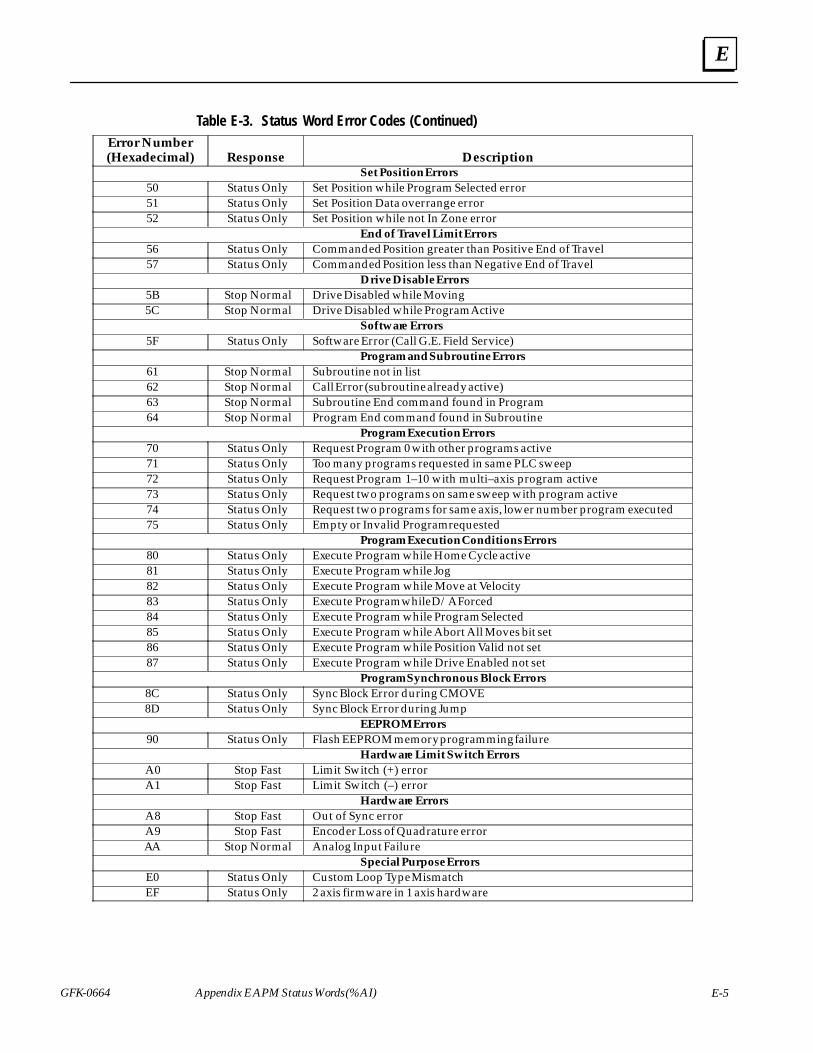
E
GFK-0664 E-5Appendix E APM Status Words (%AI)
Table E-3. Status Word Error Codes (Continued)ÁÁÁÁÁÁÁÁÁÁÁÁÁÁÁÁÁÁÁÁÁ
Error Number(Hexadecimal)
ÁÁÁÁÁÁÁÁÁÁÁÁÁÁÁ
ResponseÁÁÁÁÁÁÁÁÁÁÁÁÁÁÁÁÁÁÁÁÁÁÁÁÁÁÁÁÁÁÁÁÁÁÁÁÁÁÁÁÁÁÁÁÁÁÁÁÁÁÁÁÁÁÁÁÁÁÁÁ
Description
ÁÁÁÁÁÁÁÁÁÁÁÁÁÁÁÁÁÁÁÁÁÁÁÁÁÁÁÁÁÁÁÁSet Position ErrorsÁÁÁÁÁÁÁÁÁÁÁÁÁÁ
50ÁÁÁÁÁÁÁÁÁÁ
Status OnlyÁÁÁÁÁÁÁÁÁÁÁÁÁÁÁÁÁÁÁÁÁÁÁÁÁÁÁÁÁÁÁÁÁÁÁÁÁÁÁÁ
Set Position while Program Selected errorÁÁÁÁÁÁÁÁÁÁÁÁÁÁ
51 ÁÁÁÁÁÁÁÁÁÁ
Status OnlyÁÁÁÁÁÁÁÁÁÁÁÁÁÁÁÁÁÁÁÁÁÁÁÁÁÁÁÁÁÁÁÁÁÁÁÁÁÁÁÁ
Set Position Data overrange errorÁÁÁÁÁÁÁÁÁÁÁÁÁÁ
52 ÁÁÁÁÁÁÁÁÁÁ
Status OnlyÁÁÁÁÁÁÁÁÁÁÁÁÁÁÁÁÁÁÁÁÁÁÁÁÁÁÁÁÁÁÁÁÁÁÁÁÁÁÁÁ
Set Position while not In Zone error
ÁÁÁÁÁÁÁÁÁÁÁÁÁÁÁÁÁÁÁÁÁÁÁÁÁÁÁÁÁÁÁÁEnd of Travel Limit ErrorsÁÁÁÁÁÁÁÁÁÁÁÁÁÁ
56ÁÁÁÁÁÁÁÁÁÁ
Status OnlyÁÁÁÁÁÁÁÁÁÁÁÁÁÁÁÁÁÁÁÁÁÁÁÁÁÁÁÁÁÁÁÁÁÁÁÁÁÁÁÁ
Commanded Position greater than Positive End of TravelÁÁÁÁÁÁÁÁÁÁÁÁÁÁ
57 ÁÁÁÁÁÁÁÁÁÁ
Status OnlyÁÁÁÁÁÁÁÁÁÁÁÁÁÁÁÁÁÁÁÁÁÁÁÁÁÁÁÁÁÁÁÁÁÁÁÁÁÁÁÁ
Commanded Position less than Negative End of TravelÁÁÁÁÁÁÁÁÁÁÁÁÁÁ
ÁÁÁÁÁÁÁÁÁÁ
ÁÁÁÁÁÁÁÁÁÁÁÁÁÁÁÁÁÁÁÁÁÁÁÁÁÁÁÁÁÁÁÁÁÁÁÁÁÁÁÁ
Drive Disable Errors
ÁÁÁÁÁÁÁ5B ÁÁÁÁÁStop NormalÁÁÁÁÁÁÁÁÁÁÁÁÁÁÁÁÁÁÁÁDrive Disabled while MovingÁÁÁÁÁÁÁÁÁÁÁÁÁÁ
5CÁÁÁÁÁÁÁÁÁÁ
Stop NormalÁÁÁÁÁÁÁÁÁÁÁÁÁÁÁÁÁÁÁÁÁÁÁÁÁÁÁÁÁÁÁÁÁÁÁÁÁÁÁÁ
Drive Disabled while Program ActiveÁÁÁÁÁÁÁÁÁÁÁÁÁÁ
ÁÁÁÁÁÁÁÁÁÁ
ÁÁÁÁÁÁÁÁÁÁÁÁÁÁÁÁÁÁÁÁÁÁÁÁÁÁÁÁÁÁÁÁÁÁÁÁÁÁÁÁ
Software ErrorsÁÁÁÁÁÁÁÁÁÁÁÁÁÁ
5F ÁÁÁÁÁÁÁÁÁÁ
Status OnlyÁÁÁÁÁÁÁÁÁÁÁÁÁÁÁÁÁÁÁÁÁÁÁÁÁÁÁÁÁÁÁÁÁÁÁÁÁÁÁÁ
Software Error (Call G.E. Field Service)
ÁÁÁÁÁÁÁÁÁÁÁÁÁÁÁÁÁÁÁÁÁÁÁÁÁÁÁÁÁÁÁÁProgram and Subroutine ErrorsÁÁÁÁÁÁÁÁÁÁÁÁÁÁ
61ÁÁÁÁÁÁÁÁÁÁ
Stop NormalÁÁÁÁÁÁÁÁÁÁÁÁÁÁÁÁÁÁÁÁÁÁÁÁÁÁÁÁÁÁÁÁÁÁÁÁÁÁÁÁ
Subroutine not in listÁÁÁÁÁÁÁÁÁÁÁÁÁÁ
62 ÁÁÁÁÁÁÁÁÁÁ
Stop NormalÁÁÁÁÁÁÁÁÁÁÁÁÁÁÁÁÁÁÁÁÁÁÁÁÁÁÁÁÁÁÁÁÁÁÁÁÁÁÁÁ
Call Error (subroutine already active)ÁÁÁÁÁÁÁÁÁÁÁÁÁÁ
63 ÁÁÁÁÁÁÁÁÁÁ
Stop NormalÁÁÁÁÁÁÁÁÁÁÁÁÁÁÁÁÁÁÁÁÁÁÁÁÁÁÁÁÁÁÁÁÁÁÁÁÁÁÁÁ
Subroutine End command found in Program
ÁÁÁÁÁÁÁ64 ÁÁÁÁÁStop NormalÁÁÁÁÁÁÁÁÁÁÁÁÁÁÁÁÁÁÁÁProgram End command found in SubroutineÁÁÁÁÁÁÁÁÁÁÁÁÁÁ
ÁÁÁÁÁÁÁÁÁÁ
ÁÁÁÁÁÁÁÁÁÁÁÁÁÁÁÁÁÁÁÁÁÁÁÁÁÁÁÁÁÁÁÁÁÁÁÁÁÁÁÁ
Program Execution ErrorsÁÁÁÁÁÁÁÁÁÁÁÁÁÁ
70 ÁÁÁÁÁÁÁÁÁÁ
Status OnlyÁÁÁÁÁÁÁÁÁÁÁÁÁÁÁÁÁÁÁÁÁÁÁÁÁÁÁÁÁÁÁÁÁÁÁÁÁÁÁÁ
Request Program 0 with other programs activeÁÁÁÁÁÁÁÁÁÁÁÁÁÁ
71 ÁÁÁÁÁÁÁÁÁÁ
Status OnlyÁÁÁÁÁÁÁÁÁÁÁÁÁÁÁÁÁÁÁÁÁÁÁÁÁÁÁÁÁÁÁÁÁÁÁÁÁÁÁÁ
Too many programs requested in same PLC sweep
ÁÁÁÁÁÁÁ72 ÁÁÁÁÁStatus OnlyÁÁÁÁÁÁÁÁÁÁÁÁÁÁÁÁÁÁÁÁRequest Program 1–10 with multi–axis program activeÁÁÁÁÁÁÁÁÁÁÁÁÁÁ
73ÁÁÁÁÁÁÁÁÁÁ
Status OnlyÁÁÁÁÁÁÁÁÁÁÁÁÁÁÁÁÁÁÁÁÁÁÁÁÁÁÁÁÁÁÁÁÁÁÁÁÁÁÁÁ
Request two programs on same sweep with program activeÁÁÁÁÁÁÁÁÁÁÁÁÁÁ
74 ÁÁÁÁÁÁÁÁÁÁ
Status OnlyÁÁÁÁÁÁÁÁÁÁÁÁÁÁÁÁÁÁÁÁÁÁÁÁÁÁÁÁÁÁÁÁÁÁÁÁÁÁÁÁ
Request two programs for same axis, lower number program executedÁÁÁÁÁÁÁÁÁÁÁÁÁÁ
75 ÁÁÁÁÁÁÁÁÁÁ
Status OnlyÁÁÁÁÁÁÁÁÁÁÁÁÁÁÁÁÁÁÁÁÁÁÁÁÁÁÁÁÁÁÁÁÁÁÁÁÁÁÁÁ
Empty or Invalid Program requested
ÁÁÁÁÁÁÁÁÁÁÁÁÁÁÁÁÁÁÁÁÁÁÁÁÁÁÁÁÁÁÁÁProgram Execution Conditions ErrorsÁÁÁÁÁÁÁÁÁÁÁÁÁÁ
80ÁÁÁÁÁÁÁÁÁÁ
Status OnlyÁÁÁÁÁÁÁÁÁÁÁÁÁÁÁÁÁÁÁÁÁÁÁÁÁÁÁÁÁÁÁÁÁÁÁÁÁÁÁÁ
Execute Program while Home Cycle activeÁÁÁÁÁÁÁÁÁÁÁÁÁÁ
81 ÁÁÁÁÁÁÁÁÁÁ
Status OnlyÁÁÁÁÁÁÁÁÁÁÁÁÁÁÁÁÁÁÁÁÁÁÁÁÁÁÁÁÁÁÁÁÁÁÁÁÁÁÁÁ
Execute Program while JogÁÁÁÁÁÁÁÁÁÁÁÁÁÁ
82 ÁÁÁÁÁÁÁÁÁÁ
Status OnlyÁÁÁÁÁÁÁÁÁÁÁÁÁÁÁÁÁÁÁÁÁÁÁÁÁÁÁÁÁÁÁÁÁÁÁÁÁÁÁÁ
Execute Program while Move at Velocity
ÁÁÁÁÁÁÁ83 ÁÁÁÁÁStatus OnlyÁÁÁÁÁÁÁÁÁÁÁÁÁÁÁÁÁÁÁÁExecute Program while D/A ForcedÁÁÁÁÁÁÁÁÁÁÁÁÁÁ
84ÁÁÁÁÁÁÁÁÁÁ
Status OnlyÁÁÁÁÁÁÁÁÁÁÁÁÁÁÁÁÁÁÁÁÁÁÁÁÁÁÁÁÁÁÁÁÁÁÁÁÁÁÁÁ
Execute Program while Program SelectedÁÁÁÁÁÁÁÁÁÁÁÁÁÁ
85 ÁÁÁÁÁÁÁÁÁÁ
Status OnlyÁÁÁÁÁÁÁÁÁÁÁÁÁÁÁÁÁÁÁÁÁÁÁÁÁÁÁÁÁÁÁÁÁÁÁÁÁÁÁÁ
Execute Program while Abort All Moves bit setÁÁÁÁÁÁÁÁÁÁÁÁÁÁ
86 ÁÁÁÁÁÁÁÁÁÁ
Status OnlyÁÁÁÁÁÁÁÁÁÁÁÁÁÁÁÁÁÁÁÁÁÁÁÁÁÁÁÁÁÁÁÁÁÁÁÁÁÁÁÁ
Execute Program while Position Valid not set
ÁÁÁÁÁÁÁ87 ÁÁÁÁÁStatus OnlyÁÁÁÁÁÁÁÁÁÁÁÁÁÁÁÁÁÁÁÁExecute Program while Drive Enabled not setÁÁÁÁÁÁÁÁÁÁÁÁÁÁ
ÁÁÁÁÁÁÁÁÁÁ
ÁÁÁÁÁÁÁÁÁÁÁÁÁÁÁÁÁÁÁÁÁÁÁÁÁÁÁÁÁÁÁÁÁÁÁÁÁÁÁÁ
Program Synchronous Block ErrorsÁÁÁÁÁÁÁÁÁÁÁÁÁÁ
8C ÁÁÁÁÁÁÁÁÁÁ
Status OnlyÁÁÁÁÁÁÁÁÁÁÁÁÁÁÁÁÁÁÁÁÁÁÁÁÁÁÁÁÁÁÁÁÁÁÁÁÁÁÁÁ
Sync Block Error during CMOVEÁÁÁÁÁÁÁÁÁÁÁÁÁÁ
8D ÁÁÁÁÁÁÁÁÁÁ
Status OnlyÁÁÁÁÁÁÁÁÁÁÁÁÁÁÁÁÁÁÁÁÁÁÁÁÁÁÁÁÁÁÁÁÁÁÁÁÁÁÁÁ
Sync Block Error during Jump
ÁÁÁÁÁÁÁÁÁÁÁÁÁÁÁÁÁÁÁÁÁÁÁÁÁÁÁÁÁÁÁÁEEPROM ErrorsÁÁÁÁÁÁÁÁÁÁÁÁÁÁ
90ÁÁÁÁÁÁÁÁÁÁ
Status OnlyÁÁÁÁÁÁÁÁÁÁÁÁÁÁÁÁÁÁÁÁÁÁÁÁÁÁÁÁÁÁÁÁÁÁÁÁÁÁÁÁ
Flash EEPROM memory programming failureÁÁÁÁÁÁÁÁÁÁÁÁÁÁ
ÁÁÁÁÁÁÁÁÁÁ
ÁÁÁÁÁÁÁÁÁÁÁÁÁÁÁÁÁÁÁÁÁÁÁÁÁÁÁÁÁÁÁÁÁÁÁÁÁÁÁÁ
Hardware Limit Switch ErrorsÁÁÁÁÁÁÁÁÁÁÁÁÁÁ
A0 ÁÁÁÁÁÁÁÁÁÁ
Stop FastÁÁÁÁÁÁÁÁÁÁÁÁÁÁÁÁÁÁÁÁÁÁÁÁÁÁÁÁÁÁÁÁÁÁÁÁÁÁÁÁ
Limit Switch (+) error
ÁÁÁÁÁÁÁA1 ÁÁÁÁÁStop FastÁÁÁÁÁÁÁÁÁÁÁÁÁÁÁÁÁÁÁÁLimit Switch (–) errorÁÁÁÁÁÁÁÁÁÁÁÁÁÁ
ÁÁÁÁÁÁÁÁÁÁ
ÁÁÁÁÁÁÁÁÁÁÁÁÁÁÁÁÁÁÁÁÁÁÁÁÁÁÁÁÁÁÁÁÁÁÁÁÁÁÁÁ
Hardware ErrorsÁÁÁÁÁÁÁÁÁÁÁÁÁÁ
A8 ÁÁÁÁÁÁÁÁÁÁ
Stop FastÁÁÁÁÁÁÁÁÁÁÁÁÁÁÁÁÁÁÁÁÁÁÁÁÁÁÁÁÁÁÁÁÁÁÁÁÁÁÁÁ
Out of Sync errorÁÁÁÁÁÁÁÁÁÁÁÁÁÁ
A9 ÁÁÁÁÁÁÁÁÁÁ
Stop FastÁÁÁÁÁÁÁÁÁÁÁÁÁÁÁÁÁÁÁÁÁÁÁÁÁÁÁÁÁÁÁÁÁÁÁÁÁÁÁÁ
Encoder Loss of Quadrature error
ÁÁÁÁÁÁÁAA ÁÁÁÁÁStop NormalÁÁÁÁÁÁÁÁÁÁÁÁÁÁÁÁÁÁÁÁAnalog Input FailureÁÁÁÁÁÁÁÁÁÁÁÁÁÁ
ÁÁÁÁÁÁÁÁÁÁ
ÁÁÁÁÁÁÁÁÁÁÁÁÁÁÁÁÁÁÁÁÁÁÁÁÁÁÁÁÁÁÁÁÁÁÁÁÁÁÁÁ
Special Purpose ErrorsÁÁÁÁÁÁÁÁÁÁÁÁÁÁ
E0 ÁÁÁÁÁÁÁÁÁÁ
Status OnlyÁÁÁÁÁÁÁÁÁÁÁÁÁÁÁÁÁÁÁÁÁÁÁÁÁÁÁÁÁÁÁÁÁÁÁÁÁÁÁÁ
Custom Loop Type MismatchÁÁÁÁÁÁÁÁÁÁÁÁÁÁ
EF ÁÁÁÁÁÁÁÁÁÁ
Status OnlyÁÁÁÁÁÁÁÁÁÁÁÁÁÁÁÁÁÁÁÁÁÁÁÁÁÁÁÁÁÁÁÁÁÁÁÁÁÁÁÁ
2 axis firmware in 1 axis hardware
Index
Index-1GFK-0664
AAbort All Moves Discrete Command
(%Q), B-2
Acceleration Command, A-2
Actual Position Status Word, E-2
Actual Velocity Status Word, E-2
Analog Input Status Word, E-2
APM Immediate Commands (%AQ), C-1
APM Motion Commands, A-1
APM Status Bits (%I), D-1
APM Status Words (%AI), E-1
Axis Enabled Status Bit, D-2
BBacking–Up All APM Files in a Folder,
2-32
Block Number Command, A-2
Block Numbers, Renumbering, 2-19
CCalculating Move Distances, 3-1
Call Subroutine Command, A-3
Checking Program or Subroutine , 2-18
Clear Error Discrete Command (%Q), B-2
Clearing All APM Files in a Folder, 2-34
Clearing APM Memory, 2-48
Cmove Command, A-3
Cmove Followed by Pmove Example, 3-5
Command Block Number Status Word,E-2
Command Line, 2-9
Commanded Position Status Word, E-2
Commanded Velocity Status Word, E-2
Comment Lines, Adding, 2-17
Communications, Setting–Up, 2-40
Configuring Programs and Subroutines,2-26
Connecting the Communications Cable,2-11
Copying All APM Files in a Folder, 2-36
Copying APM Files, 2-28
Creating a Folder, 2-4
Creating a Folder, 2-30
Creating an APM File, 2-7 , 2-23
Creating and Editing Programs and Sub-routines, 2-12
CTL09–CTL12 Output Controls DiscreteCommand s (%Q), B-3
DDeleting a Folder, 2-31
Deleting an APM File, 2-25
Deleting Lines, 2-18
Discrete Commands (%Q), B-1 Abort All Moves, B-2 Clear Error, B-2 CTL09–CTL12 Output Controls, B-3 Enable Drive, B-3 Feedhold (OFF), B-5 Feedhold (ON), B-4 Find Home, B-5 Jog Minus, B-7 Jog Plus, B-8 Reset Strobe Flag, B-9
Display Mode, 2-13
DisplayingaProgram, 2-12
Drive Enabled Status Bit, D-2
Dwell Command, A-4
EEdit Mode, 2-17
Editing a Program or Subroutine, 2-17
EEPROM Operations, 2-50
Enable Drive Discrete Command (%Q),B-3
Error Codes, E-3
Error Status Bit, D-2
Establishing Communications, 2-11
Examples, Motion Program, 3-1 Cmove Followed by Pmove, 3-5
Index
Index-2 GFK-0664
Jump Command, 3-8 Multiple Cmoves, 3-7 Single Pmove, 3-3
FFaceplate Input Status CTL 01–08 Status
Bit, D-3
Feedhold (OFF) Discrete Command (%Q),B-5
Feedhold (ON) Discrete Command (%Q),B-4
File Functions, 2-23
Files, 2-22 Copying, 2-28 Creating, 2-23 Deleting, 2-25 Loading and Storing, 2-43 Printing, 2-52 Selecting, 2-23 Verifying, 2-47
Files, Hierarchy, 2-22
Find Home Discrete Command (%Q), B-5
Folder Functions (F8), 2-29
Folders, 2-22 Backing–Up All APM Files, 2-32 Clearing All APM Files, 2-34 Copying All APM Files, 2-36 Creating, 2-30 Deleting, 2-31 Locking and Unlocking, 2-35 Restoring All APM Files, 2-33 Selecting, 2-30
Folders, Hierarchy, 2-22
Force D/A Output Immediate Command,C-2
Function Keys, Help and Special, 2-10
Functions Accessed from , 2-13
GGoTo Function, 2-19
HHelp and Special Function Keys, 2-10
IImmediate Commands (%AQ)
Force D/A Output, C-2 Integrator Time Constant, C-2 Jog Acceleration, C-3 Jog Velocity, C-3 Load Parameter, C-4 Move at Velocity, C-4 Position Increment, C-5 Position Loop Time Constant, C-5 Rate Override, C-6 Set Position, C-6 Velocity Feedforward, C-7
In Error Limit Status Bit, D-3 In Zone Status Bit, D-4 Insert Mode, 2-16 Inserting Lines in a Program or Subrou-
tine, 2-16 Installing the Motion Programmer Soft-
ware, 2-2 Integrator Time Constant Immediate
Command, C-2 Introduction to APM Programming, 1-1
JJog Acceleration Immediate Command,
C-3 Jog Minus Discrete Command (%Q), B-7 Jog Plus Discrete Command (%Q), B-8 Jog Velocity Immediate Command, C-3 Jump Command, A-4 Jump Command Example, 3-8
LLoad Parameter Command, A-5 Load Parameter Immediate Command,
C-4 Loading a File from the APM to the Pro-
grammer, 2-43 Loading and Storing APM Files, 2-43 Locking Current Program Folder, 2-35
MMaking Changes to a Program or Subrou-
tine, 2-17
Index
Index-3GFK-0664
Memory, Clearing, 2-48
Message Line, 2-9
Mode, Programmer, 2-39
Motion Commands Acceleration, A-2 Block Number, A-2 Call Subroutine, A-3 Cmove, A-3 Dwell, A-4 Jump, A-4 Load Parameter, A-5 Pmove, A-5 , A-6 Velocity, A-7 Wait, A-7
Motion Program Examples, 3-1
Motion Programmer, 1-1 , 1-2 , 2-1 Functions, 2-8 Installing the Software, 2-2 Instruction Format, 1-3 Main Screen, 2-8 Startup, 2-2
Move at Velocity Immediate Command,C-4
Move Distances, Calculating, 3-1
Moving Status Bit, D-4
Moving the Cursor, 2-15
Multiple Cmoves Example, 3-7
PPausing the Print Operation, 2-56
PLC Control Active Status Bit, D-4
Pmove Command, A-5 , A-6
Ports, 2-37 Setting–Up, 2-37
Position Increment Immediate Command,C-5
Position Loop Time Constant ImmediateCommand, C-5
Position Strobe Status Bit, D-5
Position Valid Status Bit, D-5
Printer Parameters, Setting–Up, 2-52
Printer Port, Setup, 2-37
Printing, 2-52 Pausing, 2-56
Printer Parameters, 2-52 Programs and Subroutines, 2-55 Selecting Screen Print Destination, 2-54
Printing APM Files, 2-52
Program Active Status Bit, D-6
Program Edit Fields, 2-14
Program Zero Editor, 1-1 , 1-4
Programming, Overview, 1-1
Programs, Selecting and Configuring, 2-26
RRate Override Immediate Command, C-6
Renumbering Block Numbers, 2-19
Reset Strobe FlagDiscrete Command(%Q), B-9
Restoring All APM Files in a Folder, 2-33
SScreen Print Destination, Selecting, 2-54
Selecting a Folder, 2-4
Selecting a Folder, 2-30
Selecting an APM File, 2-23
Selecting Programs and Subroutines, 2-26
Selecting the Screen Print Destination,2-54
Set Position Immediate Command, C-6
Setting the Programmer Mode, 2-39
Setting–Up APM Communications, 2-40
Setting–Up Printer Parameters, 2-52
Setting–Up the Printer Serial Port, 2-37
Setting–Up the Programmer Ports, 2-37
Single Pmove Example, 3-3
Size Limitations, 2-20
Starting–Up the Motion Programmer, 2-2
Starting–Up the Motion ProgrammerSoftware, 2-4
Status Bits (%I)Axis Enabled, D-2 Drive Enabled, D-2 Error, D-2
Index
Index-4 GFK-0664
Faceplate Input Status CTL 01–08, D-3 In Error Limit, D-3 In Zone, D-4 Moving, D-4 PLC Control Active, D-4 Position Strobe, D-5 Position Valid, D-5 Program Active, D-6
Status Code Status Word, E-2
Status Code Word, E-3
Status Fields, Additional, 2-13
Status Functions, 2-21
Status Line Definition, 2-9
Status Words (%AI)Actual Position, E-2 Actual Velocity, E-2 Analog Input, E-2 Command Block Number, E-2 Commanded Position, E-2 Commanded Velocity, E-2 Status Code, E-2
Storing a File from the Programmer to theAPM, 2-45
Subroutines, Selecting and Configuring,2-26
Syntax, Checking Program or Subroutine,2-18
UUnlocking Current Program Folder, 2-35
VVelocity Command, A-7
Velocity Feedforward Immediate Com-mand, C-7
Verifying the APM with the Programmer,2-47
WWait Command, A-7