gd-2 machine - vertical express · gd-2 machine (4501am) ... the independent gear adjustment...
TRANSCRIPT

GD-2 Machine

Every attempt has been made to ensure that this documentation is as accurate and up-to-date as possible.However, Vertical Express assumes no liability for consequences, directly or indirectly, resulting from any error oromission. The material contained herein is subject to revision. Please report any problems with this manual toVertical Express, P.O. Box 2019, Memphis, Tennessee 38101.
Vertical Express • P.O. Box 2019 • Memphis, Tennessee 38101
© 2005, 2012 Vertical Express. All rights reserved.Published March, 2012
Tenth Edition Printed in the United States of America
Manual Number: 89125 v.1.1

GD-2 Machine Contents
Printed in USA March, 2012 1
Contents
Safety Precautions . . . . . . . . . . . . . . . . . . . . . . . . . . . . . . . . . . . . . . . . . . . . . . . . . . . . . . . . . . . . . . . . 3
General Safety . . . . . . . . . . . . . . . . . . . . . . . . . . . . . . . . . . . . . . . . . . . . . . . . . . . . . . . . . . . . . 3
Electrical Safety . . . . . . . . . . . . . . . . . . . . . . . . . . . . . . . . . . . . . . . . . . . . . . . . . . . . . . . . . . . . 3
Mechanical Safety . . . . . . . . . . . . . . . . . . . . . . . . . . . . . . . . . . . . . . . . . . . . . . . . . . . . . . . . . . 4
Handling . . . . . . . . . . . . . . . . . . . . . . . . . . . . . . . . . . . . . . . . . . . . . . . . . . . . . . . . . . . . . . . . . 5
Shipping . . . . . . . . . . . . . . . . . . . . . . . . . . . . . . . . . . . . . . . . . . . . . . . . . . . . . . . . . . . . . . . . . 5
Arrival of Equipment . . . . . . . . . . . . . . . . . . . . . . . . . . . . . . . . . . . . . . . . . . . . . . . . . . . . . . . . . 5
Overview . . . . . . . . . . . . . . . . . . . . . . . . . . . . . . . . . . . . . . . . . . . . . . . . . . . . . . . . . . . . . . . . . . . . . . . 7
Specifications. . . . . . . . . . . . . . . . . . . . . . . . . . . . . . . . . . . . . . . . . . . . . . . . . . . . . . . . . . . . . . 7
Dimensions . . . . . . . . . . . . . . . . . . . . . . . . . . . . . . . . . . . . . . . . . . . . . . . . . . . . . . . . . . . . . . . 8
Machine Components . . . . . . . . . . . . . . . . . . . . . . . . . . . . . . . . . . . . . . . . . . . . . . . . . . . . . . . . . . . . . . 9
Machine Assembly . . . . . . . . . . . . . . . . . . . . . . . . . . . . . . . . . . . . . . . . . . . . . . . . . . . . . . . . . . . . . . . 10
Installation . . . . . . . . . . . . . . . . . . . . . . . . . . . . . . . . . . . . . . . . . . . . . . . . . . . . . . . . . . . . . . . . . . . . . 10
Recommended Hoisting Methods . . . . . . . . . . . . . . . . . . . . . . . . . . . . . . . . . . . . . . . . . . . . . . 10
Machine Anchor Bolt Layouts and Isolation Details. . . . . . . . . . . . . . . . . . . . . . . . . . . . . . . . . . 13
Blocking and Isolation Layouts . . . . . . . . . . . . . . . . . . . . . . . . . . . . . . . . . . . . . . . . . . . . . . . . 14
Mounting the Deflector Sheave to the Machine Beams . . . . . . . . . . . . . . . . . . . . . . . . . . . . . . . 20
Bedplate, Deflector Mounting Beams and Blocking Beam Installation . . . . . . . . . . . . . . . . . . . . 22
(with deflector in the machine room) . . . . . . . . . . . . . . . . . . . . . . . . . . . . . . . . . . . . . . . . . . . . 22
Mounting the Deflector Sheave to the Deflector Mounting Beams . . . . . . . . . . . . . . . . . . . . . . . 28
Mounting the Rope Cover Kit (machines without the Hollister-Whitney "Rope Gripper") . . . . . . . 29
Mounting the Rope Cover Kit (machines with the Hollister-Whitney "Rope Gripper"). . . . . . . . . . 30
Installation of the Hollister-Whitney "Rope Gripper" . . . . . . . . . . . . . . . . . . . . . . . . . . . . . . . . . 30
Sheave Brake Mounting . . . . . . . . . . . . . . . . . . . . . . . . . . . . . . . . . . . . . . . . . . . . . . . . . . . . . 32
Rope Tension Adjustment . . . . . . . . . . . . . . . . . . . . . . . . . . . . . . . . . . . . . . . . . . . . . . . . . . . . 35
Brake Switch Wiring . . . . . . . . . . . . . . . . . . . . . . . . . . . . . . . . . . . . . . . . . . . . . . . . . . . . . . . . 37
Motor Connection . . . . . . . . . . . . . . . . . . . . . . . . . . . . . . . . . . . . . . . . . . . . . . . . . . . . . . . . . . 37
Wiring Diagrams. . . . . . . . . . . . . . . . . . . . . . . . . . . . . . . . . . . . . . . . . . . . . . . . . . . . . . . . . . . 37
Adjustment . . . . . . . . . . . . . . . . . . . . . . . . . . . . . . . . . . . . . . . . . . . . . . . . . . . . . . . . . . . . . . . . . . . . . 39
Single Solenoid Brake Adjustment. . . . . . . . . . . . . . . . . . . . . . . . . . . . . . . . . . . . . . . . . . . . . . 39
Final Adjustments. . . . . . . . . . . . . . . . . . . . . . . . . . . . . . . . . . . . . . . . . . . . . . . . . . . . . . . . . . 44

Contents GD-2 Machine
2 Vertical Express
Contents(continued)
Maintenance . . . . . . . . . . . . . . . . . . . . . . . . . . . . . . . . . . . . . . . . . . . . . . . . . . . . . . . . . . . . . . . . . . . . 46
Drive Sheave Retainer Bolt Verification. . . . . . . . . . . . . . . . . . . . . . . . . . . . . . . . . . . . . . . . . . . 46
Drive Sheave Carrier Bearing Bolt Torque Verification . . . . . . . . . . . . . . . . . . . . . . . . . . . . . . . . 49
Sheave Carrier Bearing . . . . . . . . . . . . . . . . . . . . . . . . . . . . . . . . . . . . . . . . . . . . . . . . . . . . . . 49
Baldor Motors . . . . . . . . . . . . . . . . . . . . . . . . . . . . . . . . . . . . . . . . . . . . . . . . . . . . . . . . . . . . . 49
Imperial DC Motors . . . . . . . . . . . . . . . . . . . . . . . . . . . . . . . . . . . . . . . . . . . . . . . . . . . . . . . . . 49
Lincoln AC Motors . . . . . . . . . . . . . . . . . . . . . . . . . . . . . . . . . . . . . . . . . . . . . . . . . . . . . . . . . . 52
End Thrust Test and Adjustment . . . . . . . . . . . . . . . . . . . . . . . . . . . . . . . . . . . . . . . . . . . . . . . 53
Gear Pattern Test . . . . . . . . . . . . . . . . . . . . . . . . . . . . . . . . . . . . . . . . . . . . . . . . . . . . . . . . . . 54
Gear Pattern Adjustment . . . . . . . . . . . . . . . . . . . . . . . . . . . . . . . . . . . . . . . . . . . . . . . . . . . . . 55
Backlash Adjustment. . . . . . . . . . . . . . . . . . . . . . . . . . . . . . . . . . . . . . . . . . . . . . . . . . . . . . . . 57
Sheave Replacement Procedure . . . . . . . . . . . . . . . . . . . . . . . . . . . . . . . . . . . . . . . . . . . . . . . 59
Service Information . . . . . . . . . . . . . . . . . . . . . . . . . . . . . . . . . . . . . . . . . . . . . . . . . . . . . . . . . . . . . . . 64
Gear Replacement. . . . . . . . . . . . . . . . . . . . . . . . . . . . . . . . . . . . . . . . . . . . . . . . . . . . . . . . . . 64
Secure the Car . . . . . . . . . . . . . . . . . . . . . . . . . . . . . . . . . . . . . . . . . . . . . . . . . . . . . . . . . . . . 65
Brake Removal . . . . . . . . . . . . . . . . . . . . . . . . . . . . . . . . . . . . . . . . . . . . . . . . . . . . . . . . . . . . 65
Motor Removal . . . . . . . . . . . . . . . . . . . . . . . . . . . . . . . . . . . . . . . . . . . . . . . . . . . . . . . . . . . . 66
Output Shaft Removal . . . . . . . . . . . . . . . . . . . . . . . . . . . . . . . . . . . . . . . . . . . . . . . . . . . . . . . 68
Ring Gear Replacement . . . . . . . . . . . . . . . . . . . . . . . . . . . . . . . . . . . . . . . . . . . . . . . . . . . . . . 71
O-rings and Seal Replacement . . . . . . . . . . . . . . . . . . . . . . . . . . . . . . . . . . . . . . . . . . . . . . . . 72
Bearing Replacement . . . . . . . . . . . . . . . . . . . . . . . . . . . . . . . . . . . . . . . . . . . . . . . . . . . . . . . . . . . . . . 74
Output Shaft Bearing, Sheave Side . . . . . . . . . . . . . . . . . . . . . . . . . . . . . . . . . . . . . . . . . . . . . 74
Dual Bearing Eccentric . . . . . . . . . . . . . . . . . . . . . . . . . . . . . . . . . . . . . . . . . . . . . . . . . . . . . . 74
Worm Gear Bearing Replacement . . . . . . . . . . . . . . . . . . . . . . . . . . . . . . . . . . . . . . . . . . . . . . 76
Replace the Output Shaft. . . . . . . . . . . . . . . . . . . . . . . . . . . . . . . . . . . . . . . . . . . . . . . . . . . . . 79
Installing the Gear Case on the Bedplate . . . . . . . . . . . . . . . . . . . . . . . . . . . . . . . . . . . . . . . . . 81
Brake Installation . . . . . . . . . . . . . . . . . . . . . . . . . . . . . . . . . . . . . . . . . . . . . . . . . . . . . . . . . . 81
Motor Installation . . . . . . . . . . . . . . . . . . . . . . . . . . . . . . . . . . . . . . . . . . . . . . . . . . . . . . . . . . 82
Troubleshooting Chart . . . . . . . . . . . . . . . . . . . . . . . . . . . . . . . . . . . . . . . . . . . . . . . . . . . . . . . . . . . . . 83
Replacement Parts . . . . . . . . . . . . . . . . . . . . . . . . . . . . . . . . . . . . . . . . . . . . . . . . . . . . . . . . . . . . . . . . 84
GD-2 Machine (4501AM) . . . . . . . . . . . . . . . . . . . . . . . . . . . . . . . . . . . . . . . . . . . . . . . . . . . . 84
Output Shaft Assembly (744DH1) Shipped before 02/01/03 . . . . . . . . . . . . . . . . . . . . . . . . . . . 87
Output Shaft Assembly (744DH2) Shipped after 02/01/03 . . . . . . . . . . . . . . . . . . . . . . . . . . . . 88
Brake Assemblies . . . . . . . . . . . . . . . . . . . . . . . . . . . . . . . . . . . . . . . . . . . . . . . . . . . . . . . . . 89
Single Solenoid Assembly (140V) 799AG3 . . . . . . . . . . . . . . . . . . . . . . . . . . . . . . . . . . . . . . . 90
Dual Solenoid Assembly (140V) 799AB5 . . . . . . . . . . . . . . . . . . . . . . . . . . . . . . . . . . . . . . . . . 91
Encoder/Motor Coupling (AC Motor Shown) . . . . . . . . . . . . . . . . . . . . . . . . . . . . . . . . . . . . . . . 92
Brake Switch . . . . . . . . . . . . . . . . . . . . . . . . . . . . . . . . . . . . . . . . . . . . . . . . . . . . . . . . . . . . . 93
Hoisting Parts . . . . . . . . . . . . . . . . . . . . . . . . . . . . . . . . . . . . . . . . . . . . . . . . . . . . . . . . . . . . 94
GD-2 Machine Safety Precautions
Printed in USA March, 2012 3
Safety Precautions
IMPORTANT! Read this page before any work is performed on elevator equipment. The procedures contained in this manual are intended for the use of qualified elevator personnel. In the interest of your personal safety and the safety of others, do not attempt any procedure that you are not qualified to perform.
All procedures must be accomplished in accordance with the applicable rules in the latest edition of the National Electrical Code, the latest edition of ASME A17.1, and any governing local codes.
Terms in This Manual
CAUTION statements identify conditions that may result in damage to the equipment or other property if improper procedures are followed.
WARNING statements identify conditions that may result in personal injury if improper procedures are followed.
General Safety
Before applying power to the controller, check that all factory wire connections are tight on relays, contactors, fuse blocks, resistors, and terminals on cards and DIN rail terminals. Connections loosened during shipment may cause damage or intermittent operation.
Other specific warnings and cautions are found where applicable and do not appear in this sum-mary. See the Elevator Industry Field Employees’ Safety Handbook for electrical equipment safety information on installation and service.
Electrical Safety All wiring must be in accordance with the National Electrical Code and be consistent with all state and local codes.
Use the Proper Fuse
To avoid fire hazards, use only a fuse of the correct type, voltage, and current rating. See the job specific drawings sheet (Power Supplies) for fusing information.
Electric shocks can cause personal injury or loss of life. Circuit breakers, switches, and fuses may not disconnect all power to the equipment. Always refer to the wiring diagrams. Whether the AC supply is grounded or not, high voltage will be present at many points.
Printed Circuit Cards
Printed circuit boards may be damaged if removed or installed in the circuit while applying power. Before installation and/or removing printed circuit boards, secure all power.
Always store and ship printed circuit cards in separate static bags.
Safety Precautions GD-2 Machine
4 Vertical Express
(continued)(continued)Electrical Safety Mainline Disconnect
Unless otherwise directed, always Turn OFF, Lock, and Tag out the mainline disconnect to remove power from elevator equipment. Before proceeding, confirm that the equipment is de-energized with a volt meter. Refer to the Vertical Express Employees’ Safety and Accident Prevention Program Manual for the required procedure.
Test Equipment Safety
Always refer to manufacturers’ instruction book for proper test equipment operation and adjust-ments.
Megger or buzzer-type continuity testers can damage electronic components. Connection of devices such as voltmeters on certain low level analog circuits may degrade electronic system per-formance. Always use a voltmeter with a minimum impedance of 1M Ohm/Volt. A digital voltmeter is recommended.
When Power Is On
To avoid personal injury, do not touch exposed electrical connections or components while power is ON.
Mechanical Safety See the Elevator Industry Field Employees’ Safety Handbook for mechanical equipment safety information on installation and service.

GD-2 Machine Safety Precautions
Printed in USA March, 2012 5
Static Protection Guidelines
IMPORTANT! Read this page before working with electronic circuit boards.
Elevator control systems use a number of electronic cards to control various functions of the elevator. These cards have components that are extremely sensitive to static electricity and are susceptible to damage by static discharge.
Immediate and long-term operation of an electronic-based system depends upon the proper handling and shipping of its cards. For this reason, the factory bases warranty decisions on the guidelines below.
Handling • Cards shipped from the factory in separate static bags must remain in the bags until time for installation.
• Anti-static protection devices, such as wrist straps with ground wire, are required when handling circuit boards.
• Cards must not be placed on any surface without adequate static protection.
• Only handle circuit cards by their edges, and only after discharging personal static electricity to a grounding source. DO NOT touch the components or traces on the circuit card.
• Extra care must be taken when handling individual, discrete components such as EPROMS (which do not have circuit card traces and components for suppression).
Shipping • Complete the included board discrepancy sheet.
• Any card returned to the factory must be packaged in a static bag designed for the card.
• Any card returned to the factory must be packaged in a shipping carton designed for the card.
• “Peanuts” and styrofoam are unacceptable packing materials.
Note: Refer to the Vertical Express Replacement Parts Catalog to order extra static bags and shipping cartons for each card.
Failure to adhere to the above guidelines will VOID the card warranty!
Arrival of Equipment Receiving
Upon arrival of the equipment, inspect it for damage. Promptly report all visible damage to the carrier. All shipping damage claims must be filed with the carrier.
Storing
During storage in a warehouse or on the elevator job site, precautions should be taken to protect the equipment from dust, dirt, moisture, and temperature extremes.

Safety Precautions GD-2 Machine
6 Vertical Express
This page
intentionally
left blank.
GD-2 Machine Overview
Printed in USA March, 2012 7
Overview The GD-2 Machine is a geared machine designed for elevators. Its worm and gear configuration allows speeds up to 500 fpm, maximum, and an elevator capacity of up to 5,000 lbs. 1:1, and 10,000 lbs. 2:1 maximum. The GD-2 Machine uses a drum brake with single or dual brake sole-noids. The independent gear adjustment eccentrics allow for fine backlash adjustments. Dependent on the controller drive, the GD-2 Machine can use an AC or a DC motor. The motor mounts onto a flange that will accept either motor.
There are eight (8) basic machines that may be placed in basement or overhead machine rooms:
1. RH Basement
2. LH Basement
3. RH Overhead with deflector sheave (mounted on the bedplate)
4. LH Overhead with deflector sheave (mounted on the bedplate)
5. RH Overhead with deflector sheave (mounted on the machine beams)
6. LH Overhead with deflector sheave (mounted on the machine beams)
7. RH Overhead without deflector sheave
8. LH Overhead without deflector sheave
Specifications • Maximum Sheave Shaft Load: 24,000 lbs.
(10,886kg) with 1 to 1 Roping
• Maximum Speed: 500 fpm (152 M/min.)
• Maximum Capacity: 10000 lbs. (4536kg) @ 45%
Counterweighting with 2 to 1 Roping
• Maximum Horsepower: 50 (32.3KW)
• Gear Ratios: S-57, D-65, D-83
• Brake Voltages: 140V
• Brake Gap: .003 - .005 (.076mm - .127mm)
• End Thrust: .0005” - .002” (.0127mm - .051mm)
• Backlash: .006” - .008” (.152mm - .203mm)
• Gear Oil Type for machine shipped before 02/01/03:
SAE 85W-140 Non-Phosphorous additive, 7EP ISO 460
• Gear Oil Type for machine shipped after 02/01/03:
Synthetic; Mobil Oil SHC 634; Print No.564AA2
• Gear Oil Capacity: 9 quarts (8.5L)
• DC Motor Voltage: 500V (30HP and 40HP)
• AC Motor HP: 40 (29.8KW) and 50 (32.3KW)
• NOTE: To convert inches to millimeters, multiply by 25.4. To convert pounds to kilograms, multiply by .454. To convert HP to KW multiply by .745.

Overview GD-2 Machine
8 Vertical Express
Dimensions
Hei
ght
Length
Dimensions Height Length Width TotalWeight
Overhead Machine withMachine Room Deflector
w/DC Motor 61.00 " 75.12 " 41.07 " 4500#
w/AC Motor 61.00 " 67.95 " 41.07 " 4300#
Hei
ght
Length
Overhead Machine withDeflector on Machine Beams
w/DC Motor 45.80 " 51.12 " 37.93 " 3700#
w/AC Motor 45.80 " 57.94 " 37.93 " 3500#
Basement Machine
w/DC Motor 45.40 " 51.12 " 36.93 " 3700#
w/AC Motor 45.40 " 57.94 " 36.93 " 3500#
AC MOTORDC MOTOR
Hei
ght
Hei
ght
Length Length
AC - Baldor DC - Imperial - 500V
40 HP 50 HP 30 HP 40 HP
Height 21.71 " 21.71 " 22.31 " 23.657 "
Length 28.275 " 28.275 " 25.75 " 31.125 "
Diameter 17.14 " 17.14 " 15.75 " 17.688 "
Weight 560# 572# 605# 760#
NOTE: Motors other than the ones listed will vary in size and weight. See manufacturer’s docu-ments.
Dia
met
er Deflector Sheave 25 " Diameter Sheave
Weight sheave only 400 #
GD-2 Machine Machine Components
Printed in USA March, 2012 9
Machine Components
These are the major components of the GD-2 Machine. See“Machine Assembly” on page 10.
• Bearing Plate - The steel plate (under one end of a beam) distributes the load through the supporting member.
• Bedplate - The steel platform on which the machine is placed, and it attaches to the lower machine mounting assembly.
• Blocking Beams - These steel beams (placed on the machine beams) raise the level of the machine room equipment.
• Brake Arms - The mechanical arms press the brake shoes against the brake drum. Each arm operates independently.
• Brake Arm Spring - Two supplied brake arm springs function independently to supply the necessary force to the brake shoes when the brake is de-energized. The springs create friction between the brake shoe and the brake drum to hold the suspended load. These springs work in compression, and their length is determined by the force required to hold the load.
• Brake Drum - The smooth-surfaced end of the drive sheave. When energized, the brake shoes are released from the brake drum.
• Brake Shoes - Two independent operating devices provide friction between the brake drum and the brake shoes.
• Brake Solenoid - Two independent electrically controlled solenoids that, when energized, remove pressure between the brake shoes and the brake drum.
• Brake Spring Adjustment Nut - This nut sets the proper length of the required brake spring for proper holding capacity of the brake assembly when the brake is de-energized.
• Deflector Sheave Beams - The steel beams, used for mounting the deflector sheave, when the deflector sheave is located in the machine room.
• Drive Sheave - A grooved sheave connected directly to the hoist motor armature shaft. The grooves provide the proper factor of traction between the sheave and the hoist ropes.
• Isolation Pads - Insulating material that prevents the transfer of mechanical vibration or noise from the running machine assembly to the building structure.
• Machine Beams - Overhead beams that distribute the load on the hoist motor assembly to the proper building structure.
• Motor - Provides the necessary torque and speed to move the elevator.
• Rope Gripper - An Emergency Brake that satisfies A17.1-2000 Code requirements of Sec-tion 2.19 Ascending Car Overspeed and Unintended Car Movement Protection.
• Sheave Brake - An Emergency Brake that satisfies A17.1-2000 Code requirements of Sec-tion 2.19 Ascending Car Overspeed and Unintended Car Movement Protection.
• Structural Slab - A floor slab that supports the loads normally carried by the machine beams.
• Velocity Encoder -This device is directly coupled to the armature shaft of the hoist motor. It is provided to give absolute speed feedback of the hoist motor to the elevator controller.
Machine Assembly GD-2 Machine
10 Vertical Express
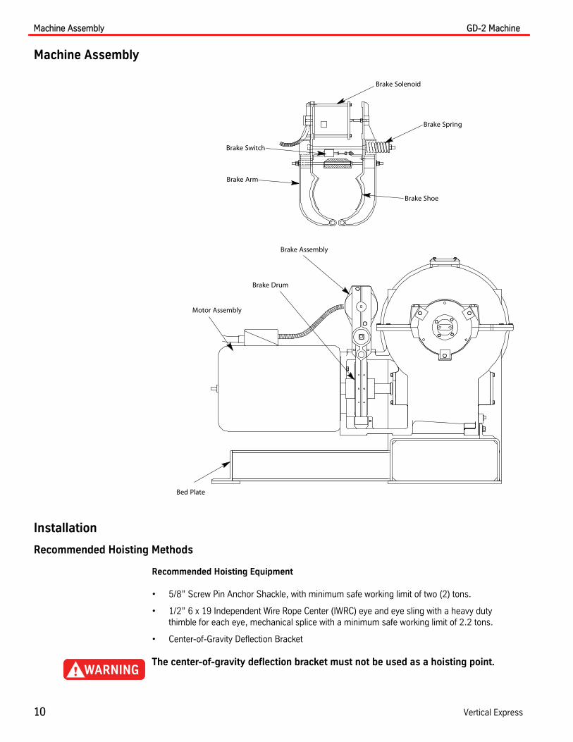
Machine Assembly
Installation
Recommended Hoisting Methods
Recommended Hoisting Equipment
• 5/8” Screw Pin Anchor Shackle, with minimum safe working limit of two (2) tons.
• 1/2” 6 x 19 Independent Wire Rope Center (IWRC) eye and eye sling with a heavy duty thimble for each eye, mechanical splice with a minimum safe working limit of 2.2 tons.
• Center-of-Gravity Deflection Bracket
The center-of-gravity deflection bracket must not be used as a hoisting point.
Brake Assembly
Bed Plate
Motor Assembly
Brake Solenoid
Brake Spring
Brake Shoe
Brake Arm
Brake Drum
Brake Switch

GD-2 Machine Installation
Printed in USA March, 2012 11
Installation(continued) Preparation
1. Ensure that the two (2) bolts holding the hoisting bar in place are securely tightened.
2. Attach the center-of-gravity deflection bracket. See Figure 1.
a. Remove the two (2) bolts that hold the drive sheave guard in place.
b. Install the deflection bracket on top of the sheave guard bracket.
c. Tighten the bolts.
Ensure that the hoisting bar, center-of-gravity deflection bracket, and screw pin anchor shackle are securely fastened and that the sling is in the proper position for the machine configuration.
Figure 1 - Recommended Hoisting
Hoisting Bar(Adjustment Handle)
1/2" 6 x 19 IWRC eye and eye sling with heavyduty thimble each eye, mechanical splicewith minimum safe working limit 2.2 tons
NOTES:Motor and machine not shown for clarity.Left hand Bedplate Machine Beam configuration shown.
Center-of-GravityDeflection Bracket

Installation GD-2 Machine
12 Vertical Express
Installation(continued) 3. Install the screw pin anchor shackle through the eye of the wire rope sling, then through the
hole in the hoisting bar.
4. Route the 1/2” wire rope sling through the proper position of the center-of-gravity deflection bracket. The bracket positions limit the tilting of different configuration machines. SeeFigure 2 for the proper location.
5. Make sure that the sleeve of the wire rope sling is not contacting the center-of-gravity deflec-tion bracket.
If excessive tilting of the machine occurs, verify the machine configurations, and that the wire rope is positioned correctly in the center-of-gravity deflection bracket.
Figure 2 - Center-of-Gravity Deflection Bracket
Center-of-Gravity Deflection Bracket
Hoist RopePosition Locations(See Chart)
1 2
3
Note: Left hand configuration shown.
5
4
Motor Size &Type
Sheave Dia. /No. Ropes {
MachineBeam
Configuration
Bedplate withDeflectorMounted inMachineRoom ‡
Rope Position / Bracket Hole
40 H.P., AC
36/8 3 4
32/8 3 4
32/6 3 4
26/6 3 3
50 H.P., AC
36/8 3 4
32/8 3 4
32/6 3 3
26/8 3 4
26/6 3 3
30 H.P., DC
36/8 3 4
32/8 3 4
32/6 1 5
26/8 1 5
26/6 1 or 2 5
40 H.P., DC
36/8 1 5
32/8 1 5
32/6 1 5
26/8 1 5
26/6 1 5
{ Number of ropes is based on 5/8" dia. ropes.‡ Bedplate mounted deflector sheave removed for hoisting.
Deflection Bracket Hole Location

GD-2 Machine Installation
Printed in USA March, 2012 13
Machine Anchor Bolt Layouts and Isolation Details
Note: All measurements are in inches. To convert inches to millimeters, multiply by 25.4 (in. X 25.4 = mm).
Figure 3 - LH and RH Machine Layout (Basement)
BOLT DETAILS
3
1.25
3.25
9.5
19
25.25
16.75
8.375
44.12512.375
11
8
3.25 19
9.5
44.12512.375
118.375
16.75
25.25
1.25
Template for GD-2 Anchor Bolts, RH Pattern
Template for GD-2 Anchor Bolts, LH Pattern
Compress to 0.937with car loaded
Drive Sheave
Drive Sheave& Output Shaft
Drive Sheave & OutputShaft
Drive Sheave
Installation GD-2 Machine
14 Vertical Express
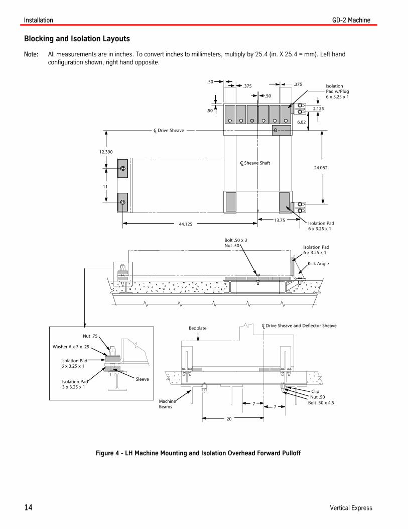
Blocking and Isolation Layouts
Note: All measurements are in inches. To convert inches to millimeters, multiply by 25.4 (in. X 25.4 = mm). Left hand configuration shown, right hand opposite.
Figure 4 - LH Machine Mounting and Isolation Overhead Forward Pulloff
77
20
MachineBeams
C Drive Sheave and Deflector SheaveLBedplate
.50
.50
.375
.50
.375
2.125
6.02
24.062
13.7544.125
11
12.390
C Sheave ShaftL
C Drive SheaveL
Isolation Pad6 x 3.25 x 1
Isolation Pad3 x 3.25 x 1
Sleeve
Nut .75
Washer 6 x 3 x .25
Isolation Pad6 x 3.25 x 1
Kick Angle
Isolation Pad6 x 3.25 x 1
IsolationPad w/Plug6 x 3.25 x 1
Nut .50Bolt .50 x 4.5
Clip
Bolt .50 x 3Nut .50

GD-2 Machine Installation
Printed in USA March, 2012 15
Blocking and Isolation Layouts(continued)
Note: All measurements are in inches. To convert inches to millimeters, multiply by 25.4 (in. X 25.4 = mm). Left hand configuration shown, right hand opposite.
Figure 5 - Machine Mounting and Isolation Overhead Forward Pulloff (Seismic)
7
7
20
MachineBeams
C Drive Sheave and Deflector SheaveLBedplate
.50
.50
.375
.50
.375
2.125
6.02
24.062
13.75044.125
11
12.390
C Sheave ShaftL
Isolation Pad6 x 3.25 x 1
Kick Angle
Isolation Pad2.375 x 3.25 x 1
Isolation Pad6 x 3.25 x 1
Washer 2.36 x 3 x .25
Nut .75
Isolation Pad6 x 3.25 x 1
IsolationPad w/Plug6 x 3.25 x 1
Nut .50
Bolt .50 x 4.5
Clip
Isolation Pad6 x 3.25 x 1
IsolationPad3 x 3.25 x 1
Sleeve
Nut .75Washer
6 x 3 x .25
C Drive SheaveL

Installation GD-2 Machine
16 Vertical Express
Blocking and Isolation Layouts(continued)
Note: All measurements are in inches. To convert inches to millimeters, multiply by 25.4 (in. X 25.4 = mm). Left hand configuration shown, right hand opposite.
Figure 6 - LH Machine Mounting and Isolation Overhead (No Pulloff)
.50
.375.375.50
5
.501
2.125
24.062
.50
12.390
11
44.125
C Sheave ShaftL
C Drive SheaveL
See Detail A
Isolation Pad6 x 3.25 x 1
Isolation Padw/Plug6 x 3.25 x 1
Bolt .50 x 3Nut .50
Detail A
Isolation Pad6 x 3.25 x 1
Isolation Pad3 x 3.25 x 1
Sleeve
Nut .75
Washer6 x 3 x .25
Remove after Machine and Beams are Secure
207
MachineBeams
Bedplate
Nut .50
Bolt .50 x 4.5
Clip
LC Drive Sheave & Deflector Sheave
GD-2 Machine Installation
Printed in USA March, 2012 17
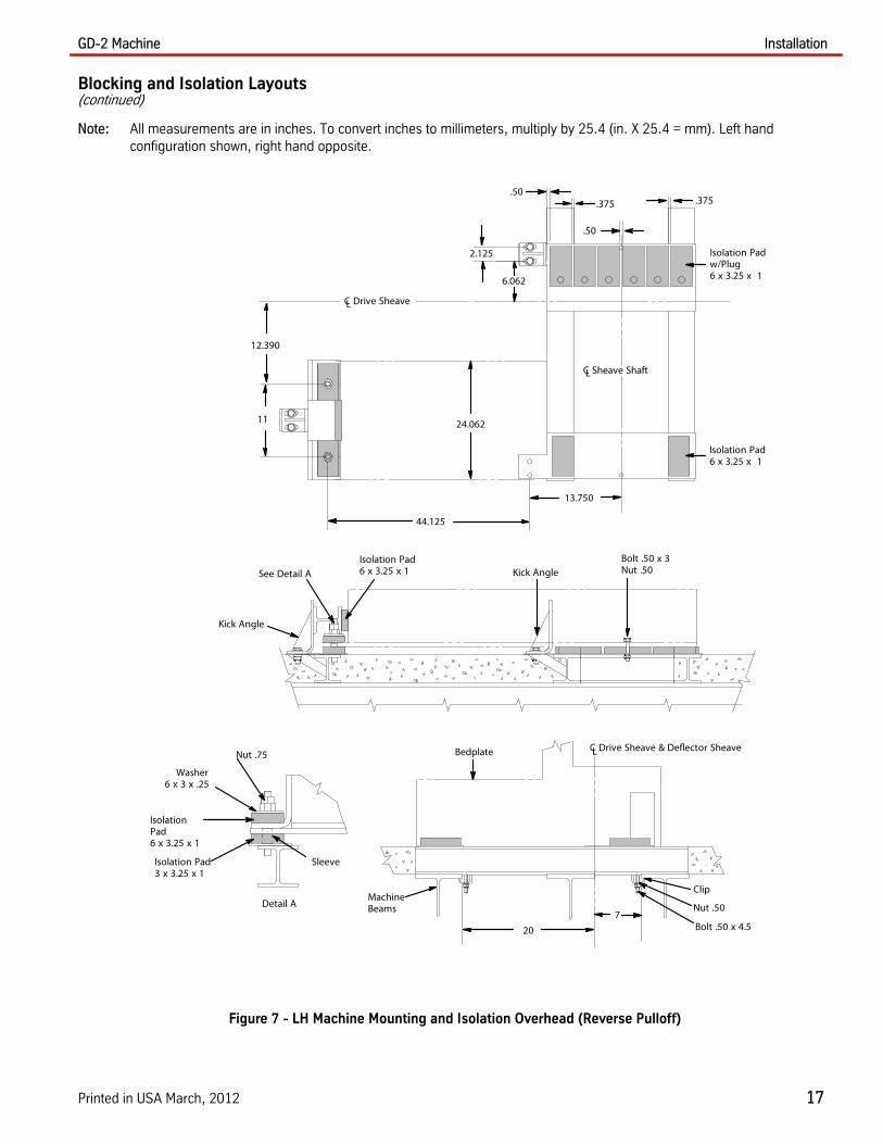
Blocking and Isolation Layouts(continued)
Note: All measurements are in inches. To convert inches to millimeters, multiply by 25.4 (in. X 25.4 = mm). Left hand configuration shown, right hand opposite.
Figure 7 - LH Machine Mounting and Isolation Overhead (Reverse Pulloff)
.50.375
2.125
6.062
.375
.50
12.390
11
44.125
24.062
13.750
20
7
MachineBeams
Bedplate
C Drive SheaveL
C Sheave ShaftL
Nut .50
Bolt .50 x 4.5
Clip
LC Drive Sheave & Deflector Sheave
See Detail AIsolation Pad6 x 3.25 x 1
Kick Angle
Kick Angle
Isolation Pad6 x 3.25 x 1
Isolation Padw/Plug6 x 3.25 x 1
Bolt .50 x 3Nut .50
Detail A
IsolationPad6 x 3.25 x 1
Isolation Pad3 x 3.25 x 1
Sleeve
Nut .75
Washer6 x 3 x .25

Installation GD-2 Machine
18 Vertical Express
Blocking and Isolation Layouts(continued)
Note: All measurements are in inches. To convert inches to millimeters, multiply by 25.4 (in. X 25.4 = mm). Left hand configuration shown, right hand opposite.
Figure 8 - Machine Mounting and Isolation (OH) with Bedplate Mounted Deflector
of Drive Sheave
47.00
16.00
Deflector Sheave
36.501.000
1.000
6.00 6.00
.375
.500
.375
.375
LC
of Deflectorand Drive Sheave
27.91
.500 x .600 Plate Provided byThyssenKrupp - Both Ends
8.375
21.50
LC
Blocking Beam
“L”see chart below
Typical
.375
.375
.375Left hand shown.Right hand opposite.
Tighten bedplate mountingbolts to 150 lb.-ft. torque.
ThyssenKrupp Part No. “L” Distance Between Pick Up Points Drive Sheave Diameter
120DM2 69.000 52.000-55.000 26.000
120DM3 60.000 46.000-49.000 32.000
ThyssenKrupp Part No. “L” Max. Distance Between Pick Up Points Drive Sheave Diameter
120DM1 See Note
57.000 26.000
63.500 32.000
68.000 36.000
Note: “L” = Distance between pickup points - (Drive Sheave Diameter/2) + 28.000

GD-2 Machine Installation
Printed in USA March, 2012 19
Blocking and Isolation Layouts(continued)
Note: All measurements are in inches. To convert inches to millimeters, multiply by 25.4 (in. X 25.4 = mm). Left hand configuration shown, right hand opposite.
Figure 9 - Machine (OH) with Bedplate Mounted Deflector Details
C
36.500
LCDrive Sheave
Deflector
W10 x 45# / FT DeflectorMounting Beam
Note 1: Remove bolts after machine is installed. Bolts are for shippingpurposes only.
Note 2: Use Anchor bolt 390AH1. Following the manufacturer’s instruc-tions, bolts must be embedded 4” into the slab. Use four bolts per AnchorPlate; outermost holes are preferred.
Drive Sheaveand Deflector
Bedplate
Tighten nut to setthis dimension at:
1.188
Detail A
See Detail A
Weld BlockingBeams to Anchor
Plates BlockingBeam
Block-ing
BeamSee Note 1
See Note 1
See Note 2
See Note 2

Installation GD-2 Machine
20 Vertical Express
Mounting the Deflector Sheave to the Machine Beams
When making overhead installations, keep the hoistway clear at all times.
The following instructions apply to Deflector Sheave Assemblies, designed specifically for clamp- type hanger installations, where I or WF beams are used as machine beams. This installation type simplifies alignment of the sheave.
1. Assemble the clips and clamp bar assemblies to the clamp plate assemblies, and then attach to the machine beams. See Figure 10.
2. Place the two clamp assemblies close together by sliding the clamp plate assembly along the beams. With the clip bolts positioned closely against the toe of the flange on the beam, snug up, but do not tighten the cap screws.
Note: Maintain a minimum distance between the clip bolts and the clamp bar bolts.
Figure 10 - Clip and Clamp Bar Assembly
3. Raise the deflector sheave into position with the shaft flat engaging clamp plate assembly.
4. Use the provided lockwashers and locknuts to install the shaft clamps. Snug up all bolts.
5. Plumb the deflector sheave, and align it with the drive sheave.
a. Slide the clamp plate assemblies along the machine beams.
b. Move the deflector sheave from side-to-side (shimming as required).
6. When the deflector sheave is plumb, and in true alignment with the drive sheave, tighten all of the connections. See Figure 11 on page 21.
ClipBolt Clip
Machine Beams
Clamp Bar Assembly
Clamp Plate AssemblyMaintain a minimum distance here

GD-2 Machine Installation
Printed in USA March, 2012 21
Mounting the Deflector Sheave to the Machine Beams(continued)
Figure 11 - Aligned Deflector Sheave
7. With the sheave bolted into final position, drill one (1) 21/32” diameter hole through each clamp plate and beam flange. See Figure 12.
a. Insert 5/8” bolts (with beveled washers) into the hole and securely fasten.
b. Make a 3/16” fillet weld, 3” long, between each clamp plate and the beam.
Note: As an alternative to through-bolting, the clamp plates can be welded to the beams.
Figure 12 - Shaft Clamps to Machine Beams
Deflector Sheaveand Drive Sheave
20.758.256 6
18.125
Blocking Beam and Isolation Pads
Bedplate
MachineBeams
Isolation Pads6 x 3.25 x 1
Isolation Pad2.38 x 3.25 x 1
Shaft Clamp
Shaft
Deflector Sheave
5/8 X 2Large Hex HeadCap Screw
5/8 Hex Nut3 Long 5/8 Lockwasher
3/16
5/8 Beveled Washer

Installation GD-2 Machine
22 Vertical Express
Mounting the Deflector Sheave to the Machine Beams(continued)
8. Mount the deflector guard to shaft clamps. See Figure 13.
Note: When special blocking is required for adequate sheave clearance, refer to the job layout.
Figure 13 - Deflector Sheave to Machine Beam
Bedplate, Deflector Mounting Beams and Blocking Beam Installation(with deflector in the machine room)
When making overhead installations, keep the hoistway clear at all times.
For all steps in this procedure, see Figure 14 through Figure 18 on page 27.
1. Use four (4) 5/8" x 1 1/2" screws, flat and lock washers, and 5/8" nuts to install and secure the deflector mounting beam gusset to the deflector mounting beams.
Notes:
• Proper distance between center punched holes must be maintained.
• Ensure that the beams are level and square as the gusset bolts are tightened.
2. Locate eight (8) scribed and center-punched holes in the top flange of the deflector mounting beams, and drill 1/4" pilot holes.
3. Drill all pilot holes to 11/16" (for mounting the bedplate).
4. Set the blocking beams in place.
5. Position the isolation pads on the blocking beams.
Clamp PlateAssembly
ShaftClamp
Deflector
DeflectorGuard
GD-2 Machine Installation
Printed in USA March, 2012 23
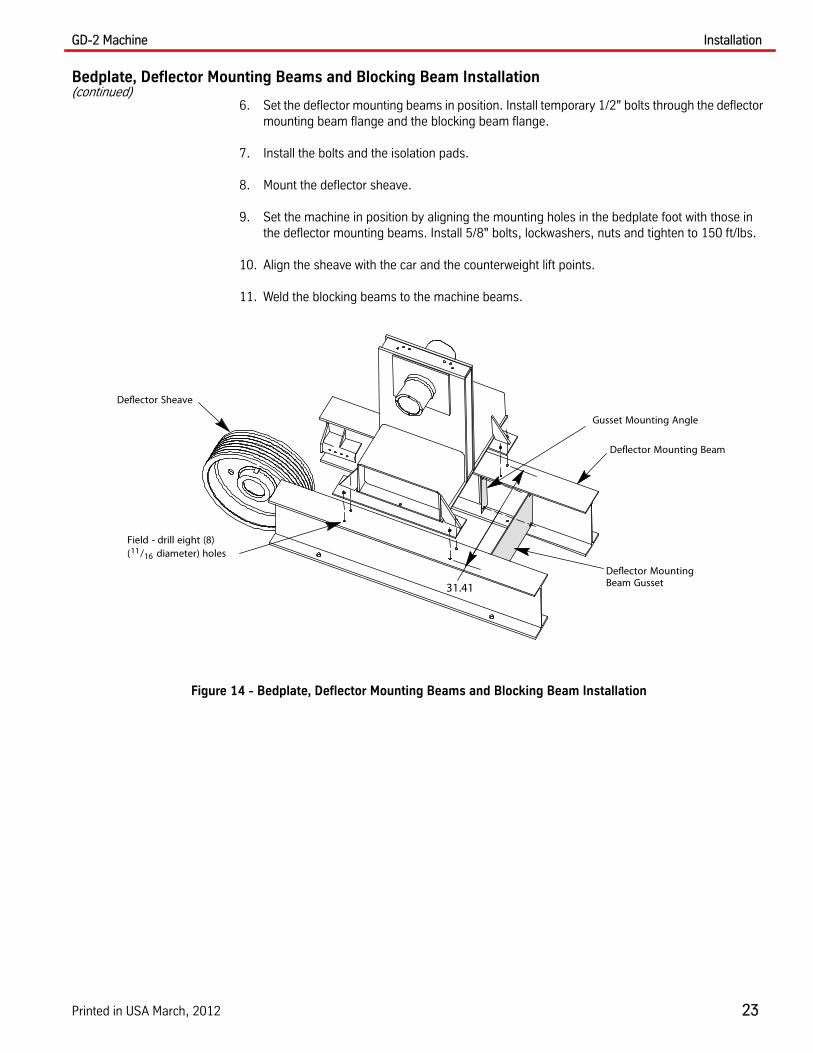
Bedplate, Deflector Mounting Beams and Blocking Beam Installation(continued)
6. Set the deflector mounting beams in position. Install temporary 1/2" bolts through the deflector mounting beam flange and the blocking beam flange.
7. Install the bolts and the isolation pads.
8. Mount the deflector sheave.
9. Set the machine in position by aligning the mounting holes in the bedplate foot with those in the deflector mounting beams. Install 5/8" bolts, lockwashers, nuts and tighten to 150 ft/lbs.
10. Align the sheave with the car and the counterweight lift points.
11. Weld the blocking beams to the machine beams.
Figure 14 - Bedplate, Deflector Mounting Beams and Blocking Beam Installation
Deflector Mounting Beam
Field - drill eight (8)(11/16 diameter) holes
Deflector Sheave
Deflector MountingBeam Gusset
Gusset Mounting Angle
31.41

Installation GD-2 Machine
24 Vertical Express
Bedplate, Deflector Mounting Beams and Blocking Beam Installation(continued)
Figure 15 - LH Machine Mounting and Isolation with Deflector Sheave in Machine Room Overhead Forward Pulloff (1 of 2)
NOTES:All measurements are in inches. To convert inches to millimeters, multiply by 25.4 (in. X 25.4 = mm).Left hand configuration shown, right hand opposite.
Deflector Sheave& Drive Sheave
Isolation Pad6 x 3.25 x 1
.375
.50
.375
.375.375
21.5 1.0
1.0
1.0
.375 typ
.50
.50
Cross Beam
See Detail A
Isolation Pad6 x 3.25 x 1
Isolation Pad2.38 x 3.24 x 1
DeflectorSheave
MachineBeams
DeflectorMountingBeam
BlockingBeam
Nut .50
Bolt .50 x 3
Drive Sheave
36.5
Deflector MountingBeam Gusset
Deflector MountingBeam Gusset
Tighten BedplateMounting Bolts to150 lb-ft. Torque
Temporary

GD-2 Machine Installation
Printed in USA March, 2012 25
Bedplate, Deflector Mounting Beams and Blocking Beam Installation(continued)
Figure 16 - LH Machine Mounting and Isolation with Deflector Sheave in Machine Room Overhead Forward Pulloff (2 of 2)
NOTES:All measurements are in inches. To convert inches to millimeters, multiply by 25.4 (in. X 25.4 = mm).Left hand configuration shown, right hand opposite.
1.188
Isolation Pad2.38 x 3.24 x 1
Sleeve
Nut .75
Washer2.36x 3x.25
Lockwasher .75
Bolt .75
Deflector Sheaveand Drive Sheave
DeflectorMountingBeam
8.375
27.910
Machine Beamsthe maximum widthfor eight (8) 5/8 "ropes is 7.500
Bolt .50 x 3
Deflector MountingBeam Gusset
Cross Beamto Machine Beam
6.35.25
Blocking Beamto Machine Beam
6.35.25
4.0 - 8.0
Tighten Bedplate MountingBolts to 150 lb-ft. Torque
Detail A
Temporary

Installation GD-2 Machine
26 Vertical Express
Bedplate, Deflector Mounting Beams and Blocking Beam Installation(continued)
Figure 17 - LH Machine Mounting and Isolation with Deflector Sheave in Machine Room (on Structural Slab) Overhead Forward Pulloff
NOTES:All measurements are in inches. To convert inches to millimeters, multiply by 25.4 (in. X 25.4 = mm).Left hand configuration shown, right hand opposite.
Typ
Typ
.25
.25
.25
Embedded Platesby General Contractor,1 x 8 x 40.5
DeflectorMountingBeam
Blocking Beam
Embedded Platesby General Contractor,1 x 8 x 40.5
Isolation Pad2.38 x 3.24 x 1
Nut .50
Isolation Pad6 x 3.25 x 1
Deflector Sheave
DeflectorSheave& Drive Sheave
.375
.50
.375
.375
.375
21.5 1.0
1.0.375 Typ
.50
.50
1.188
Detail AIsolation Pad2.38 x 3.24 x 1
Sleeve
Nut .75
Washer2.36 x 3 x .25
Lockwasher .75
Bolt .75
Drive Sheave
37.5
Deflector Sheave& Drive Sheave
12.62
36.5
Bolt .50 x 3
Bolt .50 x 3
Deflector MountingBeam Gusset
Deflector MountingBeam Gusset
DeflectorMountingBeamGusset
Temporary
Temporary
GD-2 Machine Installation
Printed in USA March, 2012 27
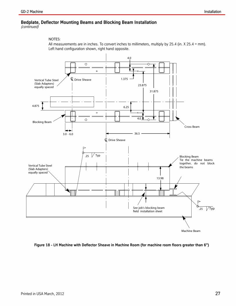
Bedplate, Deflector Mounting Beams and Blocking Beam Installation(continued)
Figure 18 - LH Machine with Deflector Sheave in Machine Room (for machine room floors greater than 6”)
NOTES:All measurements are in inches. To convert inches to millimeters, multiply by 25.4 (in. X 25.4 = mm).Left hand configuration shown, right hand opposite.
Typ
See job’s blocking beamfield installation sheet
Vertical Tube Steel(Slab Adapters)equally spaced
Machine Beam
Cross Beam
Blocking Beam
Blocking BeamTie the machine beamstogether, do not blockthe beams
Vertical Tube Steel(Slab Adapters)equally spaced
.25
.25
Typ
4.875
3.0 - 6.0 36.5
4.0
1.375
31.875
23.875
4.0
13.98
6.25
Drive Sheave
Drive Sheave

Installation GD-2 Machine
28 Vertical Express
Mounting the Deflector Sheave to the Deflector Mounting Beams
When making overhead installations, keep the hoistway clear at all times.
1. After the bedplate, deflector mounting beams, and blocking beams are secured in place, remove two (2) 0.5" x 3" bolts. See Figure 19.
2. Use the 1" x 6" bolt to adjust the horizontal position of the following:
• 2:1 Applications: The deflector sheave to the counterweight or car's compounding sheave
• 1:1 Applications: The center of the pickup point of the counterweight or car.
3. Once adjusted, lock the deflector mounting bracket into place with the locking bolt.
4. Tack weld the 1" x 6" bolt into place.
5. Install the deflector rope guard on the set screws (located on the front of the deflector mounting brackets).
Figure 19 - Mounting the Deflector Sheave to the Deflector Mounting Beams
8.375
27.910
Machine Beams
Bedplate
Deflector
1 x 6 BoltFull Threaded
DeflectorMountingBracket
Set Screw
BlockingBeams
Max. Flange Widthwith Eight (8) 5/8� Ropes is 7.5
DeflectorMountingBracket Set Screw
(see Step 3 above)
LockingBolt
Deflector Mounting Detail
1 x 6 Bolt(tack weld, seeStep 2 above)

GD-2 Machine Installation
Printed in USA March, 2012 29
Mounting the Rope Cover Kit (machines without the Hollister-Whitney "Rope Gripper")
All measurements are in inches. To convert inches to millimeters, multiply by 25.4 (in. X 25.4 = mm).
.375 x .50 Bolt
.375 x .50 Bolt
.375 Washer
.375 Nut
Deflector SideRope Cover
.50 Nut
.375 x .50 Bolt
.375 x .50 Bolt
.375 Washer
.375 Nut
Motor Side Rope Cover
.50 x 1.25 Bolt
.50 Nut
Rope Cover Support
Rope Cover Kit for Deflector Sheave in Machine Room (Overhead)
Rope Cover
Rope Cover Support
Rope BaseCover Support
.25 x .50 Bolt
.25 Washer
.25 Nut
Rope Cover Extension
.25 x .50 Bolt
.25 Washer
.25 Nut
Drive Sheave
Drive Sheave
Rope CoverSupport
Rope Cover
.25 x .50 Bolt
.25 Washer
.25 Nut
.25 x .50 Bolt
.25 Washer
.25 Nut
Anchor the Sheave Support Base and the Rope Cover Support to thefloor. Extend the Rope Cover Extension (for the assembly) to cover theropes from the sheave to the floor.
Rope Base Cover Support is not used on vertical applications.Field drill the rope cover support and the rope cover at the topand at the bottom.
Rope Cover Kit - Overhead

Installation GD-2 Machine
30 Vertical Express
Mounting the Rope Cover Kit (machines with the Hollister-Whitney "Rope Gripper")
All measurements are in inches. To convert inches to millimeters, multiply by 25.4 (in. X 25.4 = mm).
Installation of the Hollister-Whitney "Rope Gripper"
These instructions are to be used in conjunction with the Hollister-Whitney Rope Gripper component manual. Consult the manual for instructions on hose connections, alignment, wear-in, wiring, test, and operation. For installation, also see Figure 20 on page 31.
Note: The car should be roped prior to installing the rope gripper.
1. Unbolt the end channel on the mounting frame assembly.
2. Place the rope gripper mounting assembly around the hoist ropes with the open end facing away from the machine.
3. Temporarily clamp the rope gripper mounting frame assembly to the deflector mounting beams.
4. Remove the retainer rings on either side of the rope gripper (per the Hollister-Whitney Rope Gripper component manual), and take out the moveable shoe.
5. Place the rope gripper on the mounting frame assembly and install the 4" x 5/8” bolts without the washers and nuts (at this time).
6. Loosen the pivot bolts on the rope gripper.
7. Match the angle of the rope gripper to the angle of the hoist ropes.
8. Tighten the pivot bolts on the rope gripper.
9. To obtain proper alignment, slide the complete mounting assembly onto the deflector mounting beams.
Note: To align the rope gripper with the hoist ropes, see the Hollister-Whitney Rope Gripper component manual.
3/8 x 1/2 Bolt
Deflector Side Rope Cover
1/2 Nut
3/8 x 1/2 Bolt
3/8 x 1/2 Bolt3/8 Washer.375 Nut
Motor Side Rope Cover
Rope Cover Support
Hollister-WhitneyRope Gripper
CoverExtension
Rope GripperMounting Assembly
Rope Cover Channel
Deflector Rope Guard
Angle Bracket
Stationary Shoe Side
MoveableShoe Side
5/8 x 2.0 Bolts5/8 Nut, Washers,Lockwashers
Deflector Mounting Beam
Pivot Bolt
End Channel

GD-2 Machine Installation
Printed in USA March, 2012 31
Installation of the Hollister-Whitney "Rope Gripper"(continued)
Use caution as the assembly may overhang the deflector mounting beams.
10. Mark through each of the four (4) holes of the mounting assembly onto the deflector mounting beam.
11. Remove the rope gripper and the mounting assembly from the deflector mounting beam.
12. Drill clearance holes (to accept a 3/4” bolt) through the deflector mounting beams at each of the four (4) marked locations.
13. Use the provided 3/4” x 2" bolts, washers, and lockwashers to reinstall and bolt the rope gripper mounting frame assembly to the deflector mounting beams.
14. Bolt the end channel back onto the mounting frame.
15. Place the rope gripper back on the mounting frame. Ensure that the hoist ropes are against the stationary shoe.
16. Use the 5/8” bolts, washers, and nuts to bolt the rope gripper to the mounting frame.
17. Replace the moveable shoe on the rope gripper.
18. Mount the rope gripper power unit to the floor near the gripper channel frame assembly.
Figure 20 - Rope Gripper Assembly
DeflectorMountingBeam
StationaryShoe Side
MoveableShoe Side
EndChannel
RetainerRings
PivotBolt
Hollister-WhitneyRope Gripper
Rope GripperMounting Assembly
Rope CoverChannel

Installation GD-2 Machine
32 Vertical Express
Sheave Brake Mounting
Sheave Brake and Brake Mount
These instructions are to be used in conjunction with the GD-1/GD-2 Sheave Brake component manual. The sheave brake is shipped separately and must be assembled to the machine in the field.
The sheave brake spring is compressed from manufacturing. Do not remove the temporary shipping fasteners until instructed.
Roping
• Prior to installation, check the ropes for nicks and abrasions.
• Do not install ropes that are damaged.
• Do not allow ropes to become nicked, bruised, or kinked.
• Do not pull ropes over edges.
• Do not twist the ropes in any direction.
• Do not slide the rope in the drive, or in the counterweight sheave grooves. Use blocks or protective metal bands.
Shackling
Before roping the car, set the car on safeties. Install the safety slings around the crosshead to a suitable support.
1. Place a wedge over the drawing in Figure 21 to confirm the correct color and size of the wedge.
Figure 21 - Confirm Actual Wedge Size and Correct Wedge Color
5/8 ropes: Red–tipped wedge
1/2 ropes: Yellow–tipped wedge
The correct wedgesize must be used
1/2 ropes: Yellow–tipped wedge5/8 ropes: Red–tipped wedge
GD-2 Machine Installation
Printed in USA March, 2012 33
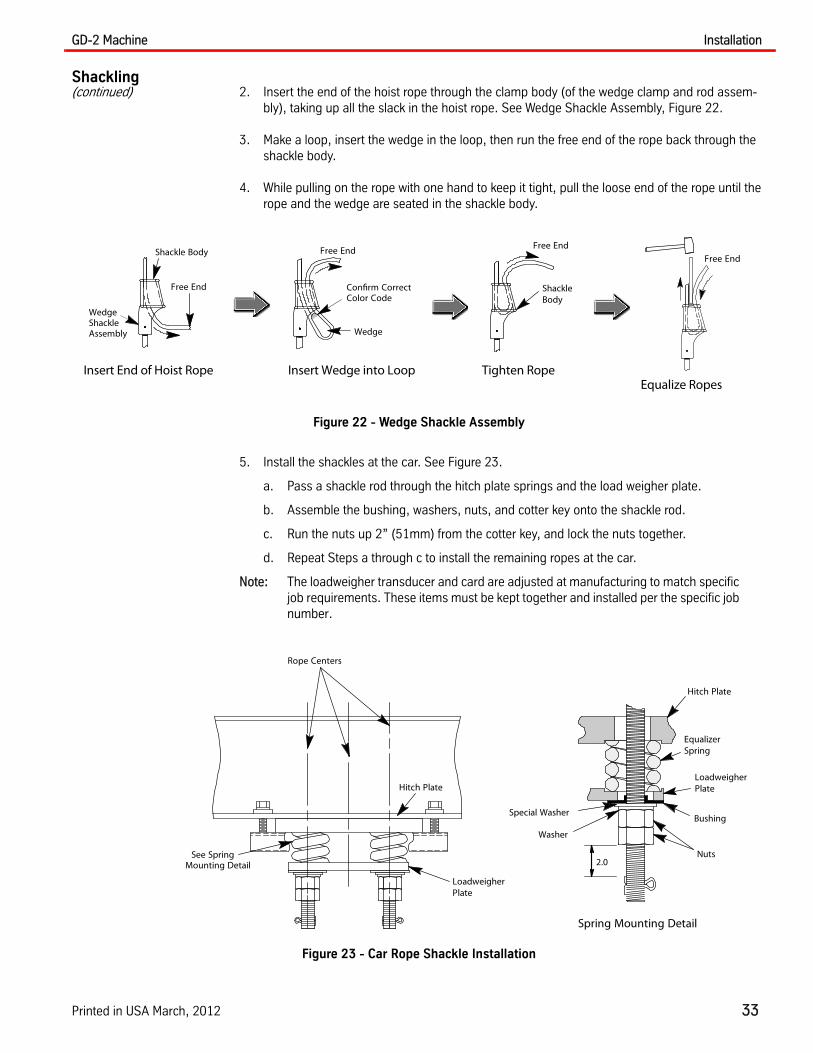
Shackling(continued) 2. Insert the end of the hoist rope through the clamp body (of the wedge clamp and rod assem-
bly), taking up all the slack in the hoist rope. See Wedge Shackle Assembly, Figure 22.
3. Make a loop, insert the wedge in the loop, then run the free end of the rope back through the shackle body.
4. While pulling on the rope with one hand to keep it tight, pull the loose end of the rope until the rope and the wedge are seated in the shackle body.
Figure 22 - Wedge Shackle Assembly
5. Install the shackles at the car. See Figure 23.
a. Pass a shackle rod through the hitch plate springs and the load weigher plate.
b. Assemble the bushing, washers, nuts, and cotter key onto the shackle rod.
c. Run the nuts up 2” (51mm) from the cotter key, and lock the nuts together.
d. Repeat Steps a through c to install the remaining ropes at the car.
Note: The loadweigher transducer and card are adjusted at manufacturing to match specific job requirements. These items must be kept together and installed per the specific job number.
Figure 23 - Car Rope Shackle Installation
Shackle Body
Free End
WedgeShackleAssembly
Insert End of Hoist Rope
Free End
Wedge
Confirm CorrectColor Code
Insert Wedge into Loop
Free End
ShackleBody
Tighten Rope
Free End
Equalize Ropes
EqualizerSpring
Bushing
LoadweigherPlate
Hitch Plate
Special Washer
Spring Mounting Detail
Rope Centers
See SpringMounting Detail
LoadweigherPlate
Hitch Plate
Washer
Nuts2.0
Installation GD-2 Machine
34 Vertical Express
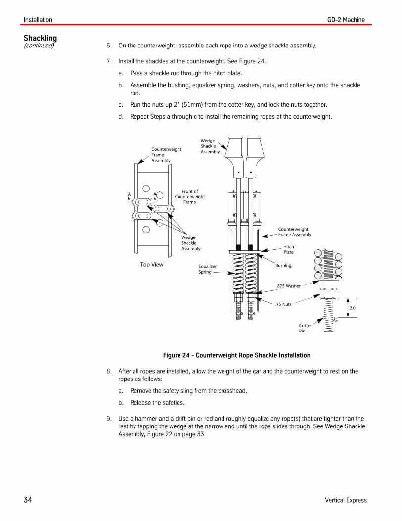
Shackling(continued) 6. On the counterweight, assemble each rope into a wedge shackle assembly.
7. Install the shackles at the counterweight. See Figure 24.
a. Pass a shackle rod through the hitch plate.
b. Assemble the bushing, equalizer spring, washers, nuts, and cotter key onto the shackle rod.
c. Run the nuts up 2” (51mm) from the cotter key, and lock the nuts together.
d. Repeat Steps a through c to install the remaining ropes at the counterweight.
Figure 24 - Counterweight Rope Shackle Installation
8. After all ropes are installed, allow the weight of the car and the counterweight to rest on the ropes as follows:
a. Remove the safety sling from the crosshead.
b. Release the safeties.
9. Use a hammer and a drift pin or rod and roughly equalize any rope(s) that are tighter than the rest by tapping the wedge at the narrow end until the rope slides through. See Wedge Shackle Assembly, Figure 22 on page 33.
.75 Nuts
EqualizerSpring
Bushing
CounterweightFrame Assembly
WedgeShackleAssembly
.875 Washer
WedgeShackleAssembly
Front ofCounterweight
Frame
CounterweightFrameAssembly
A A
Top View
HitchPlate
CotterPin
2.0

GD-2 Machine Installation
Printed in USA March, 2012 35
Shackling(continued) 10. Install a wedge locking clip on each rope. See Figure 25.
11. Arrange wedge clamps so that clamps will not rotate, then feed a small cable through the clamp bodies, and tie the cable off with a crosby clip.
12. Cut off any rope more than 6” (152mm) above the top of the wedge clamp, and tape the end of the remainder.
13. Repeat Steps 10 through 12 at the counterweight.
Figure 25 - Locking Clip Installation and Rope Clipping
Rope Tension Adjustment
Note: Perform the rope tension adjustment as soon as the car can be run on temporary operation.
1. Place the car and counterweight at the middle of the hoistway so that car and counterweight ropes and adjustment nuts can be accessed easily without moving the car. See Figure 26.
Figure 26 - Typical 1:1 Roping
WedgeLocking
Clip
Rope
Rope
Tape
13 mm.50
WedgeLocking
Clip
WedgeShackle
CrosbyClip
Locking Clip Installation
152 mm6.0
Car and CounterweightShackle Arrangement
.
Car
Counterweight
Rope
Drive Sheave
Deflector Sheave
Machine Room Floor
Installation GD-2 Machine
36 Vertical Express
Rope Tension Adjustment(continued)
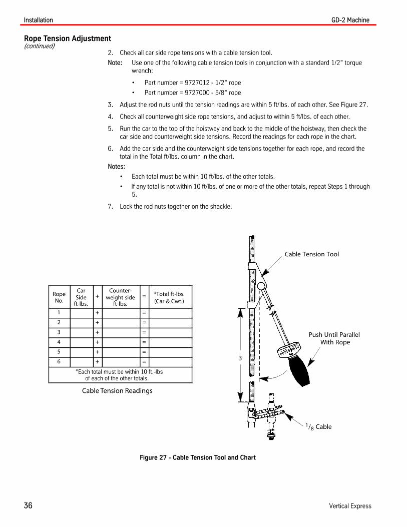
2. Check all car side rope tensions with a cable tension tool.
Note: Use one of the following cable tension tools in conjunction with a standard 1/2” torque wrench:
• Part number = 9727012 - 1/2” rope
• Part number = 9727000 - 5/8” rope
3. Adjust the rod nuts until the tension readings are within 5 ft/lbs. of each other. See Figure 27.
4. Check all counterweight side rope tensions, and adjust to within 5 ft/lbs. of each other.
5. Run the car to the top of the hoistway and back to the middle of the hoistway, then check the car side and counterweight side tensions. Record the readings for each rope in the chart.
6. Add the car side and the counterweight side tensions together for each rope, and record the total in the Total ft/lbs. column in the chart.
Notes:
• Each total must be within 10 ft/lbs. of the other totals.
• If any total is not within 10 ft/lbs. of one or more of the other totals, repeat Steps 1 through 5.
7. Lock the rod nuts together on the shackle.
Figure 27 - Cable Tension Tool and Chart
RopeNo.
CarSide
ft-lbs.+
Counter-weight side
ft-lbs.= *Total ft-lbs.
(Car & Cwt.)
1 + =
2 + =
3 + =
4 + =
5 + =
6 + =
*Each total must be within 10 ft.-lbsof each of the other totals.
Cable Tension Readings
3
Cable Tension Tool
1/8 Cable
Push Until ParallelWith Rope

GD-2 Machine Installation
Printed in USA March, 2012 37
Brake Switch Wiring The Brake Switch Wiring Harness is shipped disconnected from the brake switch. Because different controller designs can require the use of a normally open (NO) or normally closed (NC) contact, it will be necessary to refer to your specific job wiring diagrams to wire the harness to the correct NO or NC contact on the brake switch.
1. Connect the brake switch harness to the NO or NC contact on the brake switch as specified by the job specific wiring diagrams.
2. Connect the opposite end of the brake switch harness to the designated controller terminals. Refer to the job specific wiring diagrams.
Motor Connection Use the job wiring diagrams with the motor configuration information to connect the motor to the controller. See Figure 28 and Figure 29 on page 38.
Before operating the machine, refer to the appropriate product manual and verify that the drive parameters for the job are set correctly.
Wiring Diagrams
Figure 28 - Motor Configuration Wiring (1 of 2)
AC Motor Configurations
1
47
3
6 9 8 5
2
1
9
6
8 54
7
3 2
Frame Size286326404
Frame Size254256
1
96
38 5
47
2
Frame Size286326404
Baldor 9 Lead Y-Connected Configurations
1 (U)
(V)
(W)
6
2
5
4 3
(U)
(V)
(W)
(T1)
(T3)
(T2)
1 (U)
(V)
(W)
6
2
5
4 3
(U)
(V)
(W)
(T1)
(T3)
(T2)
Baldor 9 Lead Delta Configurations
1 (U)2(U) (T1)
(V)6 5(V) (T3)
(W)4 3(W) (T2)
Low VoltageHigh Voltage
High Voltage
1
4
7
3
6
85
2
9
Frame Size254256
L3L2
L1
1 (U)2(U) (T1)
(V)6 5(V) (T3)
(W)4 3(W) (T2)
Low Voltage

Installation GD-2 Machine
38 Vertical Express
Wiring Diagrams(continued)
Figure 29 - Motor Configuration Wiring (2 of 2)
12 Lead AC Motor Configuration
1
(U) (U)
(V) (V)
(W) (W)
410
7
93
612
118
2 5
1
4
10
7
9
3
612
11 8
25
Frame Size
286
326
404
Frame Size
254
256
(T1)
(T3)
(T2)
(T1)
(T3)
(T2)
1 (U) (U)
(V) (V)
(W) (W)4
10
7
9
3
6
12
1182 5
1
4
10
7 9
3
6
1211 8 25
Frame Size
286
326
404
Frame Size
254
256
(T1)
(T3)
(T2)
(T1)
(T3)
(T2)
1 (U)
(V)
(W)
6
2
5
MC1
MC1
MC14 3
1 (U)
(V)
(W)
6
2
5
MC1
MC1
MC14 3
1 (U)
(V)
(W)
6
2
5
MC1
MC1
MC14 3
1 (U)
(V)
(W)
6
2
5
MC1
MC1
MC14 3
12 Lead 460VAC Delta and WYE Geared Motor Configuration
12 Lead 230VAC Delta and WYE Geared Motor Configuration
DC Motor Lead Configuration
MOTORARMA-TURE
SH4
SH3
SH1
SH2
MA1 MA2
TAC50 Brake Configuration
B1 B2
Brake CoilTAC50
V+ BLS
Brake Switch
TAC50-04 Brake Configuration
EBRK++ EBRK--
EmergencyBrake Coil
Main Brake Switch
G24 BSLM
BSLE
Emergency Brake Switch
BRK++ BRK--
Main Brake Coil
G24
GD-2 Machine Adjustment
Printed in USA March, 2012 39
Adjustment
Single Solenoid Brake Adjustment
Before anyone is allowed to ride on the platform, adjustment of the brake must be complete.
Required Tools and Materials
• Bearing Oil
• Flint Paper (Grade 240 or finer)
• Degreaser (biodegradable, non-polluting)
• 1/4” (6mm) Flat Screwdriver
• Tape Measure
• Hex Wrenches
• Wire Brush
• M6 Bolt
• Torque Wrench and Adaptor
• Feeler Gauges
• Open End Wrenches: 10mm, 11mm, 12mm, 13mm, 14mm, 15mm, 16mm, 17mm, 19mm
Preparation
1. Verify that any required compensation chains or rope assemblies have been installed.
2. On construction jobs, verify that hoistway barricades are in place to prevent unauthorized access.
Disassembly, Cleaning, and Lubrication
Take care that no contaminants come in contact with brake parts.
1. Land the counterweight of the empty car onto the buffers.
2. Turn OFF, Lock, and Tag out the mainline disconnect.
3. Remove the spring adjustment nut and washer, the brake spring, the spring locator, and the spring bolt. See Figure 30 on page 40 for all steps in this procedure.
4. Clean the threads of the spring bolt with a wire brush, and lubricate them with grease.
5. Measure and record the uncompressed brake spring length. Verify that the brake spring diameter is 2 3/4”(70mm).
6. Disconnect the brake wiring from the junction box (mounted on the motor).
7. Remove the flex conduit from the junction box.
Adjustment GD-2 Machine
40 Vertical Express
Single Solenoid Brake Adjustment(continued)
8. On the sheave side:
a. Measure and record the length of the brake stop adjustment bolt that extends past the stop adjustment locknut.
b. Remove the stop adjustment locknut, the nut, and the flat washer from the brake stop adjustment bolt.
9. On the gear side:
a. Loosen the brake stop adjustment locknut and nut.
b. Loosen the inside locknut, and remove the brake stop adjustment bolt from the machine housing.
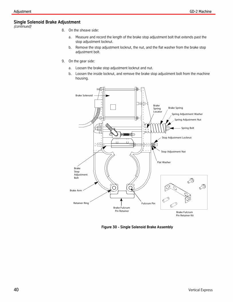
Figure 30 - Single Solenoid Brake Assembly
Brake Solenoid
Brake Spring
Spring Adjustment Nut
Spring Bolt
Stop Adjustment Nut
Flat Washer
Brake Arm
BrakeStopAdjustmentBolt
Stop Adjustment Locknut
Retainer Ring
Spring Adjustment WasherLocatorSpringBrake
Fulcrum Pin
Brake Fulcrum Pin Retainer Brake Fulcrum
Pin Retainer Kit

GD-2 Machine Adjustment
Printed in USA March, 2012 41
Single Solenoid Brake Adjustment(continued)
Remove and Clean the Brake Arm Assemblies
If the brake fulcrum pin retainer is not present, order one from the Warranty Department.
1. From the brake fulcrum pin retainer, remove the set screws and the retainer on the gear housing side.
a. Install an M6 bolt in the brake arm pins.
b. Remove the brake arm pins by pulling on the M6 bolt installed in Step a.
c. Remove the brake arms.
Note: The brake arm pins can be removed only toward the motor.
2. Lightly sand, thoroughly wash, and coat with bearing oil the brake arm pins and the brake arm bores.
3. Ensure that the brake linings are tightly riveted to the brake shoe assemblies, that the rivets are recessed a minimum of 1/16” (1.6 mm) within the brake linings, and that the brake linings are a minimum of 1/8” (3.2 mm) thick.
Remove and Clean the Solenoid
1. Remove the brake solenoid from the brake arm, and ensure that the dust seal is not damaged.
a. Remove the front plate of the brake solenoid. See Figure 31.
b. Remove the solenoid sleeve and plunger.
2. If the solenoid armature is coated with a manufacturing-applied dry lubrication (black coating), wipe it with a clean, dry cloth. If the coating is worn, replace it with a new armature that has the proper coating.
3. Store the armature to prevent any damage or contamination.
4. Thoroughly clean the inside of the solenoid sleeve and the front plate assembly.
Figure 31 - Solenoid (exploded view)
Front Plate SolenoidSleeve
DustSeal
SolenoidPlunger
Coil

Adjustment GD-2 Machine
42 Vertical Express
Single Solenoid Brake Adjustment(continued)
Reassembly and Preliminary Adjustments
1. Reassemble the brake solenoid, and be careful not to pinch the solenoid wiring.
a. Assemble the brake solenoid to the brake arm that it was removed from.
b. Verify that the brake solenoid armature moves freely in the solenoid assembly.
2. Install the brake arms, the pivot pins, the set screws, and the fulcrum pin retainer.
a. Reconnect the flex conduit and the brake wiring.
b. Verify that the brake arms will move freely.
3. Verify that the brake shoes are centered horizontally on the brake drum.
4. Use a .002” (.05 mm) feeler gauge, check for shoe-to-drum contact on both sides of the brake shoe at the top, the center, and the bottom of the drum.
a. Place the feeler gauge on the edge of the brake drum, push one of the brake arms against the drum, and verify that the gauge cannot be pulled out at the top, the bottom, and the middle of shoe.
b. Repeat Step a for the other brake arm.
5. If the brake shoe does not make 90% contact, sand in the shoes as follows:
a. Remove the spring adjusting nut, the washer, the brake spring, and the bolt.
b. Place adhesive-backed sandpaper (appx. 80 grit) around the entire surface of the brake drum.
c. Hold one brake arm against the drum, and rotate the drum back and forth.
d. If the shoe does not have 90% contact, repeat Step c.
e. Repeat Steps b through d (if necessary) for the other brake arm until 90% contact is achieved.
f. Remove the sandpaper and any adhesive from the brake drum.
6. Install the brake spring bolt, the brake spring locator, the spring washer, and the adjustment nut.
a. Tighten the spring adjustment nut until the brake spring is compressed 1/2” (12.7 mm) from its uncompressed length (recorded earlier).
b. Disconnect the brake wires from the controller.
c. Turn ON the mainline disconnect.
d. With the brake collapsed on the brake drum, run the car on Inspection Speed until the
brake drum is at 2120 F.
Do not let the brake drum exceed 2120 F. Ensure that the unbalanced load on the platform (car) plus the collapsed brake does not present an overload to the motor or controller.
e. Land the counterweight of the empty car onto the buffers.
f. Turn OFF, Lock, and Tag out the mainline disconnect.
g. Remove the spring adjustment nut, the washer, the brake spring, and the spring bolt and verify that the shoes are slightly burnished.
h. If the linings are not properly burnished, repeat Steps d through g of Step 6.

GD-2 Machine Adjustment
Printed in USA March, 2012 43
Reassembly and Preliminary Adjustments(continued)
7. From the gear side, install the brake stop adjustment bolt.
8. From the sheave side, install the washer, the nut, and the locknut.
9. Tighten the adjustment nut and locknut to obtain the thread extension dimension recorded ear-lier in “Disassembly, Cleaning, and Lubrication”.
Preliminary Shoe Adjustment
1. Ensure that the solenoid pin contacts the center of the stroke adjustment bolt.
2. Turn (by hand), the brake stop adjustment bolt assembly in the housing until the brake shoe on the sheave side is just pulled into contact with the brake drum.
3. Hold the brake stop adjustment bolt, and temporarily tighten the locknut to the housing.
4. On the gear side, pull the brake arm back against the flat washer, and turn the stop adjustment nut until the shoe-to-drum clearance is .020” (.51 mm).
5. Hold the stop adjustment nut, and tighten the locknut.
6. Loosen the brake stop adjustment bolt locknut from the housing.
7. Holding the brake arm against the stop washer, turn the brake stop adjustment bolt assembly clockwise until the brake shoe (on the gear side) clears the brake drum by .008” (.20 mm).
8. Hold the brake stop adjustment bolt, and retighten the locknut to the housing.
9. Install the brake spring bolt, the spring washer, and the adjustment nut. Tighten the spring adjustment nut until the brake spring is compressed 1/2” (12.7 mm) from its uncompressed length (recorded earlier).
10. Push the solenoid plunger completely back into the brake solenoid assembly.
a. Adjust the stroke adjustment bolt to 1/4” (6 mm) between the solenoid plunger and the stroke adjustment bolt.
b. Hold the stroke adjustment bolt, and tighten the adjustment bolt locknut.
c. Verify that the solenoid pin retainer does not restrict the movement of the solenoid pin.
Final Shoe Adjustment
1. Turn ON the mainline disconnect.
2. With the controller on Inspection Operation, electrically energize the brake.
3. If the brake arms do not contact the stops, de-energize the brake and adjust the stroke adjust-ment bolt for a full pick.
Note: The arms should just lightly contact the stops. Do not allow excessive pressure.

Adjustment GD-2 Machine
44 Vertical Express
Final Adjustments Note: To make the final adjustments to the GD-2 Machine Brake, the controller must be able to run from the platform.
Brake Spring Tension Adjustment
For Construction Platforms
1. Verify the proper counterweight.
2. Position the platform at the bottom terminal landing.
3. Tighten the spring adjustment nut until the spring is fully compressed; then turn it counter-clockwise one (1) turn.
4. Place 50% of the capacity load on the platform.
Do not load the platform beyond 50% of the contract capacity. To prevent accidental loss of traction, add weights 100 lbs. at a time.
5. Turn OFF, Lock, and Tag out the mainline disconnect.
Note: In order to prevent excessive movement in the following steps, be ready to quickly tighten the brake spring adjustment nut, or press on the brake arm assemblies.
6. Pry open the brake arms to allow the brake drum to rotate about an inch. Release the brake arms so that they close on a moving drum, and verify that the brake stops the car.
7. Slowly loosen the spring adjustment nut and repeat the previous step until the car no longer comes to a stop. Tighten the brake spring adjustment nut clockwise one (1) turn.
8. Measure and record the compressed brake spring length.
9. Subtract this compressed spring length from the uncompressed brake spring length (recorded earlier).
1. Increase the spring tension by the amount calculated in the previous step.
Note: This increase effectively doubles the spring tension recorded. This adjustment ensures that the brake will hold 50% of capacity, which is the maximum load for a construction platform (plus a safety factor).
For Use by Contractors (Temporary Car) or for Final Adjustment
1. Verify that the proper compensation is installed.
2. Verify the proper counterweight. Place a balanced load on the elevator with the car in the cen-ter of the hoistway. When the brake is manually opened, the car should not drift.
3. Turn ON the mainline disconnect.
4. Position the platform at the bottom terminal landing.
5. Tighten the spring adjustment nut until the spring is fully compressed, and then turn it counter-clockwise one (1) turn.
GD-2 Machine Adjustment
Printed in USA March, 2012 45
Final Adjustments(continued)
Do not load the platform beyond 50% of the contract capacity. To prevent accidental loss of traction, add weights 100 lbs. at a time
6. Place 125% of the capacity load on the car.
7. Turn OFF, Lock, and Tag out the mainline disconnect.
Note: In order to prevent excessive movement in the following steps, be ready to quickly tighten the brake spring adjustment nut, or press on the brake arm assemblies.
8. Pry open the brake arms to allow the brake drum to rotate about an inch. Release the brake arms so that they close on a moving drum, and verify that the brake stops the car.
9. Slowly loosen the spring adjustment nut and repeat Step 6 until the car no longer comes to a stop. Tighten the brake spring adjustment nut clockwise one and one-half (1 1/2) turns.
The maximum brake spring length is exactly four (4) inches. Verify the length of the brake spring, and tighten to adjust it to exactly 4 inches.
10. Turn ON the mainline disconnect.
11. Turn the doors OFF, and run the car to the top landing.
12. Verify that the brakes hold 125% at the top landing. If the brakes fail to hold the 125% load, increase the brake spring compression until it will.
13. Position the platform at the bottom terminal landing, and remove the load.
Brake Arm Adjustment
1. Run the platform up and down, and adjust the stroke adjustment bolt so that when the brake picks, the brake arms will gently contact the stop adjustment nuts.
2. If either of the brake shoes drags the drum while the car is running, adjust the shoe-to-drum clearance with the stroke adjustment bolt and the stop adjustment nuts.
3. Run the car up and down until the brake solenoid assembly reaches normal operating temper-ature.
4. Run the car to the top floor, and Turn OFF, Lock, and Tag out the mainline disconnect.
5. Drift the car up to land the counterweights.
6. Place the controller on Inspection Operation, and turn ON the mainline disconnect.
7. Electrically energize the brake, and verify with a feeler gauge that both brake shoes clear the brake drum by a minimum of .005” (.13 mm).
Note: If the clearance is less than .005”(.13 mm), adjust the stop adjustment nut to obtain a minimum of.005”(.13 mm), and then retighten all locknuts.
The brake pick voltage is set in relationship to the spring pressure. If the spring pressure is increased, the pick voltage must be verified to ensure proper brake oper-ation.
Maintenance GD-2 Machine
46 Vertical Express
Maintenance
Drive Sheave Retainer Bolt Verification
The GD-2 drive sheave retainer bolts and sheave bearing carrier bolts must be checked annually and after every impacted load event or test such as a safety and buffer test.
Failure to check the bolt torque annually or after impacted loading may cause a crack in the drive sheave hub.
Recommended Tools
• 175 ft/lbs torque wrench
• 70 ft/lbs beam torque wrench
• 15/16" and 3/4" sockets and ratchet
• Feeler gauges
• Scribe
1. Begin with an empty car at the top landing, with the doors closed and the door switch turned OFF, and set the controller to Inspection Operation.
2. Turn OFF, Lock, and Tag out the mainline disconnect.
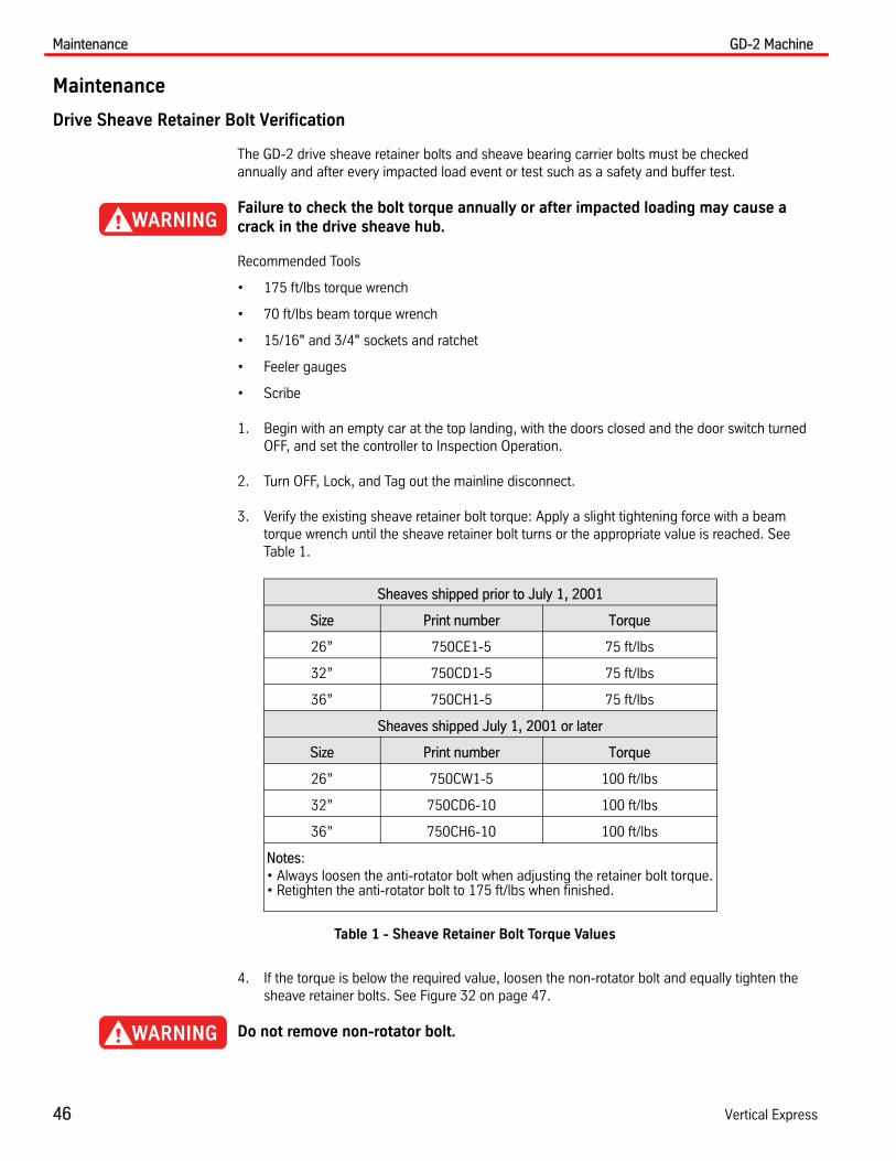
3. Verify the existing sheave retainer bolt torque: Apply a slight tightening force with a beam torque wrench until the sheave retainer bolt turns or the appropriate value is reached. See Table 1.
Table 1 - Sheave Retainer Bolt Torque Values
4. If the torque is below the required value, loosen the non-rotator bolt and equally tighten the sheave retainer bolts. See Figure 32 on page 47.
Do not remove non-rotator bolt.
Sheaves shipped prior to July 1, 2001
Size Print number Torque
26” 750CE1-5 75 ft/lbs
32” 750CD1-5 75 ft/lbs
36” 750CH1-5 75 ft/lbs
Sheaves shipped July 1, 2001 or later
Size Print number Torque
26” 750CW1-5 100 ft/lbs
32” 750CD6-10 100 ft/lbs
36” 750CH6-10 100 ft/lbs
Notes: • Always loosen the anti-rotator bolt when adjusting the retainer bolt torque.• Retighten the anti-rotator bolt to 175 ft/lbs when finished.

GD-2 Machine Maintenance
Printed in USA March, 2012 47
Drive Sheave Retainer Bolt Verification(continued)
Figure 32 - Non-Rotator Bolt
5. Run the elevator on Inspection Operation Up and Down several times to verify proper opera-tion.
6. Repeat Step 3 and Step 5 until the correct torque setting is maintained.
7. Cycle the elevator on Automatic Operation with the doors OFF for several complete hoistway runs, then return to the top landing and place the elevator on Inspection Operation.
8. Check the retainer bolt torque.
• If correct: Return the elevator to service.
• If not correct: Repeat Step 3 through Step 7 until the required torque value is maintained after Automatic Operation.
9. GD-2 Machines shipped July 1, 2001 or later: Inspect the hole located in the center of the retainer plate, and verify that the output shaft is not contacting the retainer plate.
• If clearance cannot be visibly confirmed: Try to insert a small feeler gauge between the output shaft and the retainer plate.
• If clearance is not present: Inspect the keyway location for a crack. Contact Field Engineer-ing if there is no clearance present, whether or not a crack in the sheave is found.
• If clearance is present: Place the elevator into service.
Non-Rotator Bolt

Maintenance GD-2 Machine
48 Vertical Express
Drive Sheave Retainer Bolt Verification(continued)
10. GD-2 Machines shipped prior to July 1, 2001: No inspection hole in the center of the retainer plate:
a. Place the elevator on Inspection Operation at the top landing, and Turn OFF, Lock, and Tag out the mainline disconnect.
b. Remove one of the retainer bolts and determine if there is clearance between the retainer plate and the output shaft.
Helpful Tip: For improved future inspections, an inspection hole could be drilled in the center of the retainer plate while the plate is removed.
• If clearance is present: Proceed to Step 11.
• If clearance cannot be determined: Remove all retainer bolts and the retainer plate.
c. Measure and record the distance between the end of the output shaft and the face of the drive sheave.
d. Scribe a mark on the gear case at the non-rotator angle. This mark should extend approx-imately 1" above the non-rotator angle. See Figure 33.
e. Reinstall the retainer plate, and torque to the appropriate value from Table 1 on page 46.
f. Measure how far the mark (on the gear case at the non-rotator angle) has moved.
• If the mark is less than the recorded distance from Step 10c: Perform Step 5 through Step 8.
• If the mark is equal to the recorded distance: Inspect for a crack in the drive sheave hub above the keyway. If a crack is not present, contact Field Engineering.
11. Before placing the elevator back into service, cycle the elevator and verify operation with the doors OFF.
Figure 33 - Measure the Non-Rotator Angle Movement
Scribe Mark
Non-Rotator Angle
Non-rotator bolt removed for clarity.

GD-2 Machine Maintenance
Printed in USA March, 2012 49
Drive Sheave Carrier Bearing Bolt Torque Verification
Note: Before starting this procedure, verify that the Drive Sheave Retainer Bolt Verification has been completed.
1. Begin with an empty car at the top landing, with the doors closed and the door switch turned OFF, and set the controller to Inspection Operation.
2. Turn OFF, Lock, and Tag out the mainline disconnect.
3. Use a beam torque wrench, and slightly tighten the sheave retainer bolt until it turns or the torque reading reaches 70ft/lbs.
Note: If the torque does not reach 70ft/lbs, then tighten the drive sheave carrier bolts. If the sheave brake is present, the sheave brake must have the manual brake release installed and the sheave brake pads lifted from the drive sheave rim surface during adjustment. See the GD-1 GD-2 Sheave Brake component manual.
4. Use the torque wrench and tighten the carrier bolts in a "X" pattern until they are 50 ft/lbs. See “Measure and Adjust the Weave of the Drive Sheave” on page 61.
5. Continue tightening the carrier bolts, adding 5 ft/lbs each time, until 70 ft/lbs is achieved. Do not exceed 70ft/lbs.
6. Before placing the elevator back into service, cycle the elevator and verify operation with the doors OFF.
Sheave Carrier Bearing
Annually grease bearings with approximately 1 oz. of grease. Recommended grease is Part Number 70313.
Baldor Motors Baldor Motors have seal bearings, which do not require lubricating.
Imperial DC Motors
Brushes
Brush maintenance includes inspection for proper seating, sparking, chattering, grooving, wear, and pressure. Spare brushes should be kept on hand and installed when required.
Install New Brushes (when required)
1. Rest the brush on the abrasive side of the paper.
2. Place 80-grit garnet commutator paper between the brush and the commutator.
3. Work the garnet paper back and forth until the curvature of the brush fits the commutator.
Note: On open loop equipment, never replace over half of the brushes at any one time.
Maintenance GD-2 Machine
50 Vertical Express
Imperial DC Motors(continued)
Commutators
Ensure that the commutators are smooth, highly polished, and free of dirt, oil, grease or moisture. If the surface of the commutator is dull and black (excessive sparking), clean it with a fine commuta-tor stone or garnet commutator paper (do not use emery cloth).
If the commutator requires finishing in a lathe, ensure the center to the bearing journals is within .001 Total Indicator Reading (TIR) with a surface finish of 16 micro-inches or more. After undercut-ting mica, renew the finish with garnet commutator paper.
Failure to restore the undercut will result in sparking, excessive brush wear, and ultimate damage to the commutator.
When dirt, oil, grease, or moisture is found on the commutator, completely clean the commutator with a hard, lint-free cloth. Clean between the segments with a hardwood wedge or undercutting tool. Determine the source of dirt, oil, grease, or moisture, and take measures to prevent deposits on the commutator.
Windings
Keep foreign material off of the windings.
Failure to keep the windings clean may result in short circuits, grounding of insulated surfaces, and increased rising temperatures.
The operating conditions will determine the frequency of cleaning the windings. However, it is a good policy to clean the windings at least once a year. Wipe off any greasy or oily deposits with a lint-free cloth dipped in a suitable solvent. Follow cleaner instructions carefully regarding proce-dures, methods, cautions, and warnings.
Do not leave solvent deposits on the windings. Remove non-conductive dust using compressed air (not over 50 P.S.I.). Do not blow directly into the windings. If solvent deposits are heavy or highly conductive, use a vacuum cleaner with a plastic crevice tool attachment to clean the machine.
Ball Bearings
The speed and operating conditions determine the frequency of re-greasing the ball bearings.

GD-2 Machine Maintenance
Printed in USA March, 2012 51
Imperial DC Motors(continued)
Greasing the Motor
Imperial motors are properly greased when they leave manufacturing and do not require lubrication when installed.
1. Clean the exterior of the motor.
2. Remove both the grease plug and the relief plug.
3. If grease has hardened, remove the hardened lubricant (which has accumulated in the area around the relief plug), with a wooden or plastic stick. In severe conditions, run the motor until the bearing chamber is warmed to a temperature which allows the grease to flow more easily.
4. Re-grease the motor with a low pressure grease gun.
Note: The motor must be stationary.
5. Run the motor until new grease flows from the drain plug. Ensure that the bearing chamber is two-thirds full of grease.
6. Replace grease and relief plugs.
Note: The motor must be stationary.
Lubricate the motor if it has been in storage for six months or longer. See Table 2 for lubrication guidelines.
Table 2 - Lubrication Guide for ambient temperature of 0° to 104° F.
Notes:
• For motors supplied with roller bearings, divide table values by 3. For operation in other than ambient temperature, contact the manufacturer.
• Unless otherwise shown on nameplate, the standard medium temperature grease (0° to 255° F.) is Shell Alvania #2.
• Do not use equivalent greases, they may not be chemically compatible.
• Do not use silicone grease in DC equipment.
• Lubrication should be done with the shaft stationary.
DutyMotor RPM
Through 1800 3600
Normal - Eight hours per day, normal loading, clean environment, 104° F. max. ambient. 12 months 12 months
Severe - Twenty-four hours per day, or shock vibration loading, dirt or dust environment, 104° F to 150° F ambient. 6 months 6 months
Harsh - Heavy shock or vibration, harsh environment 3 months 3 months
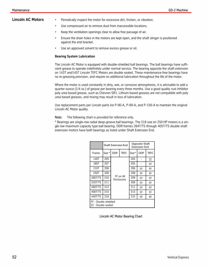
Maintenance GD-2 Machine
52 Vertical Express
Lincoln AC Motors • Periodically inspect the motor for excessive dirt, friction, or vibration.
• Use compressed air to remove dust from inaccessible locations.
• Keep the ventilation openings clear to allow free passage of air.
• Ensure the drain holes in the motors are kept open, and the shaft slinger is positioned against the end bracket.
• Use an approved solvent to remove excess grease or oil.
Bearing System Lubrication
The Lincoln AC Motor is equipped with double-shielded ball bearings. The ball bearings have suffi-cient grease to operate indefinitely under normal service. The bearing opposite the shaft extension on 143T and145T Lincoln TEFC Motors are double sealed. These maintenance-free bearings have no re-greasing provision, and require no additional lubrication throughout the life of the motor.
Where the motor is used constantly in dirty, wet, or corrosive atmospheres, it is advisable to add a quarter ounce (1/4 oz.) of grease per bearing every three months. Use a good quality rust inhibitor poly urea based grease, such as Chevron SR1. Lithium based greases are not compatible with poly urea based greases, and mixing may result in loss of lubrication.
Use replacement parts per Lincoln parts list P-90-A, P-99-A, and P-156-A to maintain the original Lincoln AC Motor quality.
Note: The following chart is provided for reference only.
* Bearings are single-row radial deep-groove ball bearings. The 318 size on 250 HP motors is a sin-gle row maximum capacity type ball bearing. ODR frames 284T/TS through 405T/TS double shaft extension motors have both bearings as listed under Shaft Extension End.
Shaft Extension End Opposite ShaftExtension End
Frame Size * DDP TEFC Size* DDP TEFC
140T 205
FF on AllEnclosures
203 - ZZ
180T 207 205 - FF
210T 208 206 FF FF
250T 309 208 FF FF
280T/TS 310 209 FF FF
320T/TS 311 309 FF FF
380T/TS 313 311 FF FF
400T/TS 315 313 FF FF
440T/TS 318 315 FF FF
FF - Double shieldedZZ - Double sealed
Lincoln AC Motor Bearing Chart

GD-2 Machine Maintenance
Printed in USA March, 2012 53
End Thrust Test and Adjustment
A verified, balanced load with the car and counterweight must be on the elevator via shackle-to- shackle, or with the hoist ropes removed from the drive sheave.
1. Install a dial indicator on the brake hub. See Figure 34.
Figure 34 - Dial Indicator on Brake Hub
2. Place the dial indicator on an area of the brake drum with the smallest variation of run-out.
3. Block open the brake arms so that the brake shoes are clear of the brake drum.
4. Pull the worm shaft, hold it in one direction, and zero the dial indicator.
5. Push the worm shaft to the end of travel (in the opposite direction), and read the amount of worm shaft travel.
Note: Pull or push the drive sheave to move the worm.
a. If the total displacement is greater than .002" (.05 mm), remove the amount of shims from the end cap to obtain readings between .0005" (.01 mm) and.002" (.05 mm).
b. If there is no movement at all, then add a .002" (.05 mm) shim to the thrust cap, and mea-sure again.
Excessive pre-load will generate heat and premature wear. End thrust greater than .002" (.05 mm) will cause premature bearing failure.
c. If there is still no movement, or excessive movement, repeat Step 4 and Step 5 until the appropriate movement is obtained.
6. Remove the dial indicator, and remove the brake arm blocking.
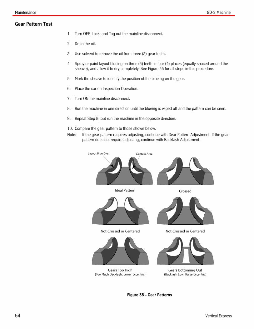
Maintenance GD-2 Machine
54 Vertical Express
Gear Pattern Test
1. Turn OFF, Lock, and Tag out the mainline disconnect.
2. Drain the oil.
3. Use solvent to remove the oil from three (3) gear teeth.
4. Spray or paint layout blueing on three (3) teeth in four (4) places (equally spaced around the sheave), and allow it to dry completely. See Figure 35 for all steps in this procedure.
5. Mark the sheave to identify the position of the blueing on the gear.
6. Place the car on Inspection Operation.
7. Turn ON the mainline disconnect.
8. Run the machine in one direction until the blueing is wiped off and the pattern can be seen.
9. Repeat Step 8, but run the machine in the opposite direction.
10. Compare the gear pattern to those shown below.
Note: If the gear pattern requires adjusting, continue with Gear Pattern Adjustment. If the gear pattern does not require adjusting, continue with Backlash Adjustment.
Figure 35 - Gear Patterns
Not Crossed or Centered
Gears Too High(Too Much Backlash, Lower Eccentric)
Gears Bottoming Out(Backlash Low, Raise Eccentric)
Crossed
Not Crossed or Centered
Ideal Pattern
Layout Blue Dye Contact Area

GD-2 Machine Maintenance
Printed in USA March, 2012 55
Gear Pattern Adjustment
Note: The ring gear position is fixed. The gear case and worm are the moving adjustable components.
The Wear Pattern is in Line, But Shifted to One Side
1. Loosen the retaining clip bolts and the housing anti-torque bolt. See Figure 36.
a. If the wear pattern is in line, but shifted toward the drive sheave:
Move the wear pattern away from the sheave - Equally turn all hex set screws 1/8 to 1/4 counter-clockwise, and then tighten the retaining clip bolts.
b. If the wear pattern is in line but shifted away from the drive sheave:
Move the wear pattern toward the sheave - Loosen the retaining clip bolts and turn all hex set screws 1/8 to 1/4 turn clockwise equally, and then tighten the retaining clip bolts.
2. Tighten the anti-torque bolt to 120 ft. lb.
3. After each adjustment, repeat the Gear Pattern Test procedure and the Gear Pattern Adjust-ment procedure until the gear pattern is correct.
4. Once the gear pattern is correct, proceed to the Backlash Adjustment section.
Figure 36 - Gear Pattern Adjustment Bolts
Retaining Ring
Allen Set Screw
Retaining Ring Bolt
Clip
Clip Bolt
Anti-TorqueBolt

Maintenance GD-2 Machine
56 Vertical Express
Gear Pattern Adjustment(continued)
Wear Pattern is Crossed
1. Look down on the gear pattern to determine which wear pattern is shifted the farthest away from the center of the gear.
2. Loosen the retainer clip bolts and the housing anti-torque bolt.
3. Move the wear pattern. See Figure 37.
• Move the wear pattern to the right:
a. Move the outboard eccentric handle toward the motor, in the direction that the wear pattern is located on the tooth.
b. Move the handle away from the face of the tooth.
• Move the wear pattern to the left:
a. Move the sheave side eccentric toward the motor, in the direction that the wear pattern is located on the tooth.
b. Move the handle away from the face of the tooth.
4. After each adjustment, repeat the Gear Pattern Test procedure until the gear pattern is correct.
Note: Usually, once the wear patterns are in line with each other they will tend shift away from the center of the gear. See the “The Wear Pattern is in Line, But Shifted to One Side” on page 55, and complete the steps in this section.
5. Once the gear pattern is correct, proceed to the Backlash Adjustment section.
Figure 37 - Crossed Gear Wear Pattern
To Move the Wear Pattern to the Right - Move the outboard handle toward the motor.
Motor
Move Wear Pattern Right
To Move the Wear Pattern to the Left - Move the sheave side handle toward the motor.
Motor
Move Wear Pattern Left
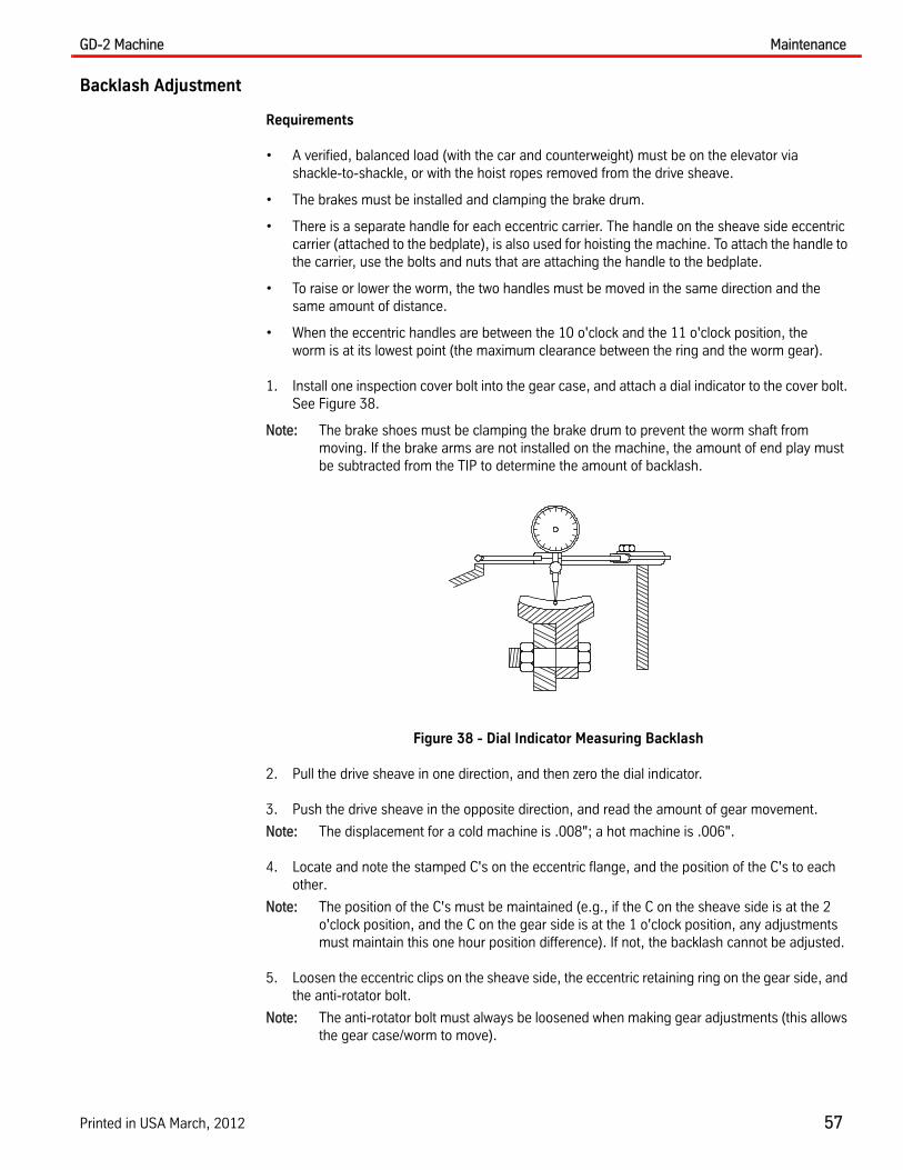
GD-2 Machine Maintenance
Printed in USA March, 2012 57
Backlash Adjustment
Requirements
• A verified, balanced load (with the car and counterweight) must be on the elevator via shackle-to-shackle, or with the hoist ropes removed from the drive sheave.
• The brakes must be installed and clamping the brake drum.
• There is a separate handle for each eccentric carrier. The handle on the sheave side eccentric carrier (attached to the bedplate), is also used for hoisting the machine. To attach the handle to the carrier, use the bolts and nuts that are attaching the handle to the bedplate.
• To raise or lower the worm, the two handles must be moved in the same direction and the same amount of distance.
• When the eccentric handles are between the 10 o'clock and the 11 o'clock position, the worm is at its lowest point (the maximum clearance between the ring and the worm gear).
1. Install one inspection cover bolt into the gear case, and attach a dial indicator to the cover bolt. See Figure 38.
Note: The brake shoes must be clamping the brake drum to prevent the worm shaft from moving. If the brake arms are not installed on the machine, the amount of end play must be subtracted from the TIP to determine the amount of backlash.
Figure 38 - Dial Indicator Measuring Backlash
2. Pull the drive sheave in one direction, and then zero the dial indicator.
3. Push the drive sheave in the opposite direction, and read the amount of gear movement.
Note: The displacement for a cold machine is .008"; a hot machine is .006".
4. Locate and note the stamped C's on the eccentric flange, and the position of the C's to each other.
Note: The position of the C's must be maintained (e.g., if the C on the sheave side is at the 2 o'clock position, and the C on the gear side is at the 1 o'clock position, any adjustments must maintain this one hour position difference). If not, the backlash cannot be adjusted.
5. Loosen the eccentric clips on the sheave side, the eccentric retaining ring on the gear side, and the anti-rotator bolt.
Note: The anti-rotator bolt must always be loosened when making gear adjustments (this allows the gear case/worm to move).

Maintenance GD-2 Machine
58 Vertical Express
Backlash Adjustment(continued)
6. Adjust the backlash:
• To increase backlash, move the two C's up toward the12 o'clock position, no more than 1/2”.
• To decrease backlash, move the C's away from the12 o'clock position, no more than 1/2”.
7. Tighten the eccentric clips on the sheave side.
8. Tighten the eccentric retaining ring and the anti-rotator bolt.
9. Check backlash with the dial indicator.
10. Repeat Steps 2 through 9 until the correct backlash is attained.
11. Check the Gear Pattern. See the “Gear Pattern Test” on page 54. If adjustment is required, see the “Gear Pattern Adjustment” on page 55.
12. Verify that the gear pattern wear matches the ideal gear pattern wear. See Figure 39.
a. Remove the dial indicator.
b. Install the inspection hole cover.
c. Rope the machine.
d. Test the car and machine for proper operation.
e. Return the car to service.
Figure 39 - Ideal Gear Pattern Wear
Layout Blue Dye Contact Area

GD-2 Machine Maintenance
Printed in USA March, 2012 59
Sheave Replacement Procedure
Recommended Tools
• Necessary hoistway rigging to hang the car
• Necessary machine room rigging to lift the drive sheave
• Torque wrench
• 1/2”(24 mm) end wrench
• 1/2”(24 mm) drive socket
• 1/2”(24 mm) drive ratchet
• Breaker bar
• Spacer (1 3/4”section of 3“ pipe)
• Washer
• Hammer
• Heavy wall socket
• Starrett 196 or 196M dial indicator
Sheave Removal
1. Place the car on Inspection Operation.
2. Place the empty car at the top landing.
3. Turn OFF, Lock, and Tag out the mainline disconnect.
4. Trip the governor, and set the safety.
5. Tie the car off with chokers to secure the car at the top landing. Position the car to allow sufficient slack in the ropes for removal.
6. Remove the hoist ropes from the drive sheave.
7. Setup rigging in the machine room to support the drive sheave and use chokers to secure the sheave. See Figure 40.
Figure 40 - Support the Drive Sheave

Maintenance GD-2 Machine
60 Vertical Express
Sheave Removal(continued)
Note the location of grease fittings to avoid breaking them when attaching the sling to the sheave.
8. Remove the four (4) drive sheave carrier bolts. See Figure 41.
9. Remove the three (3) drive sheave retaining bolts, and remove the drive sheave retainer.
10. Place the spacer (1 3/4” section of 3” pipe or similar material) over the end of the output shaft.
11. Replace the drive sheave retainer - Use three (3) of the long drive sheave carrier bolts, and put these bolts through the outer set of holes that line up with the threaded holes in the sheave.
12. Equally tighten the three (3) bolts in the drive sheave retainer until all bolts are tight. Do not overtighten the bolts. Sharply strike the center of the retainer plate with a hammer. This action should produce slack in the bolts.
Note: The output shaft and sheave carrier are tapered. Once the sheave is moved a small amount, it can be removed by hand.
Figure 41 - Replace the Drive Sheave Retainer
Keyway
Drive SheaveCarrier Bolts (4)
Drive SheaveRetaining Bolts (3)
Drive SheaveRetainer
Output Shaft
Drive Sheave
Sheave Carrier
Drive Sheave Retainer
Drive SheaveCarrier Bolts (4)
Spacer(1 3/4 section of 3.0 pipe)
Hoisting equipmentmust be installed
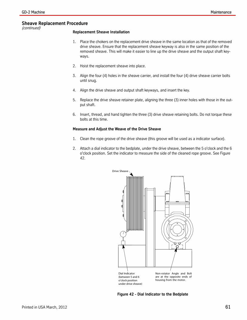
GD-2 Machine Maintenance
Printed in USA March, 2012 61
Sheave Replacement Procedure(continued)
Replacement Sheave Installation
1. Place the chokers on the replacement drive sheave in the same location as that of the removed drive sheave. Ensure that the replacement sheave keyway is also in the same position of the removed sheave. This will make it easier to line up the drive sheave and the output shaft key-ways.
2. Hoist the replacement sheave into place.
3. Align the four (4) holes in the sheave carrier, and install the four (4) drive sheave carrier bolts until snug.
4. Align the drive sheave and output shaft keyways, and insert the key.
5. Replace the drive sheave retainer plate, aligning the three (3) inner holes with those in the out-put shaft.
6. Insert, thread, and hand tighten the three (3) drive sheave retaining bolts. Do not torque these bolts at this time.
Measure and Adjust the Weave of the Drive Sheave
1. Clean the rope groove of the drive sheave (this groove will be used as a indicator surface).
2. Attach a dial indicator to the bedplate, under the drive sheave, between the 5 o'clock and the 6 o'clock position. Set the indicator to measure the side of the cleaned rope groove. See Figure 42.
Figure 42 - Dial Indicator to the Bedplate
Dial Indicator(between 5 and 6o’clock positionunder drive sheave)
Drive Sheave
Non-rotator Angle and Boltare at the opposite ends ofhousing from the motor.

Maintenance GD-2 Machine
62 Vertical Express
Measure and Adjust the Weave of the Drive Sheave(continued)
3. Number the four (4) drive sheave carrier bolts, and make four (4) marks on the outer edge of the drive sheave corresponding to the bolts. See Figure 43.
4. Tighten the drive sheave carrier bolts.
a. Use the torque wrench and an "X" pattern, and tighten the carrier bolts to 50 lb-ft (e.g., 1,3,4,2).
b. Continue tightening the carrier bolts, adding 5 lb-ft each time, until 70 lb-ft is achieved. Do not exceed 70 lb-ft.
Figure 43 - Number and Tighten the Sheave Carrier Bolts
5. Rotate the drive sheave until the outer edge mark corresponding to the #1 carrier bolt is aligned to the probe of the dial indicator. Set the dial indicator to zero (0), and this will become the ref-erence point for adjusting the weave of the drive sheave.
6. With the dial indicator, check for TIR of ±.005” by rotating the drive sheave clockwise one (1) complete revolution. Stop the rotation of the sheave.
7. Record each measurement of each number when the number on the sheave is even with the dial indicator. Use the table below to record your readings.
8. For all readings with negative values, the weave must be drawn outward, away from the machine.
a. Loosen the bolts with the negative values. The torque on the opposite bolts will fall off.
b. Re-torque the positive number bolts to 70 lb-ft., and then re-torque the bolts that had negative readings.
c. Repeat Step 3, 4, and 5 until TIR of ±.005” is obtained.
Sheave Readings
BoltNumber
1
2
3
4
4
1
2
3
“X” to indicate dial indicator“0” reference 4
1
2
3
Carrier Bolt

GD-2 Machine Maintenance
Printed in USA March, 2012 63
Sheave Replacement Procedure(continued)
9. Reinstall the sheave retainer and bolts, and torque the bolts. See Table 3.
Note: Do not over torque the bolts.
Table 3 - Brake Torque
Final Adjustments
1. Replace the sheave retainer, and torque the drive sheave retainer bolts to 100 lb-ft.
2. Replace the ropes.
3. Once the drive sheave has been properly aligned, check the ropes for proper tension.
4. Remove the chokers securing the car.
5. Release the safety and the governor.
6. Turn ON the mainline disconnect
7. Place the car on Inspection Operation.
8. With the weight now on the drive sheave, run the car down a few landings and then back up.
9. Repeat the original weave measurements to ensure the weave of the drive sheave has not changed.
Note: If the weave of the drive sheave has drifted out of TIR of ±.005”, continue the adjustments until TIR of ±.003” is achieved.
10. Lightly pry at the 5 o'clock position and the 8 o'clock positions of the drive sheave, and re-torque the bolts.
Note: With the weight now on the drive sheave, adjustments to the drive sheave will be easier. Prior to loosening the torque, rotate the negative values of the drive sheave to the 12 o'clock position. The counterweight and the car weight will assist in the movement and adjustment of the drive sheave.
Do not loosen or remove the sheave retainer bolts during this adjustment.
11. Cycle the elevator with the doors disconnected to ensure proper operation.
12. Return the car to service.
Sheaves shipped prior to July 1, 2001
Size Print number Torque
26” 750CE1-5 75 ft/lbs
32” 750CD1-5 75 ft/lbs
36” 750CH1-5 75 ft/lbs
Sheaves shipped July 1, 2001 or later
Size Print number Torque
26” 750CW1-5 100 ft/lbs
32” 750CD6-10 100 ft/lbs
36” 750CH6-10 100 ft/lbs
Notes: • Always loosen the anti-rotator bolt when adjusting the retainer bolt torque.• Retighten the anti-rotator bolt to 175 ft/lbs when finished.

Service Information GD-2 Machine
64 Vertical Express
Service Information
Gear Replacement Required Tools
Qty. Description
Layout blueing
Starrett 196 or 196M dial indicator (or equivalent with single tree)
Test weights
Hoisting equipment
Frame with a top beam (to have 21" of gear case travel)
Rigging equipment
Set of feeler gauges
Welding gloves
Bearing heater (optional) for a 4 1/2" (114.3 mm) diameter shaft
1 1/2” section 3" OD pipe
2 24" tall or greater stands
1 5 lb. hammer
1 2-ton beam trolley
1 1/2-ton hoist
1 Tape measure
2 Drift pins
1 Scribe
1 1/4” or 3/8” torque wrench in/lbs up to 200 ft/lbs
1 1/2" drive torque wrench
1 1/2"drive ratchet
1 1/2" drive breaker bar
1 ea. 1/2" drive point socket 30 mm, 24 mm, 19 mm, 14 mm
1 1/2" drive 1 1/8” point socket
1 ea. 20 mm, 10 mm wrench
1 19 mm open end wrench
1 ea. 30 mm, 24 mm, 13 mm box end wrench
1 1" combination wrench
1 3/4" hand reamer
3 4" x 4" x 20" blocks of wood
1 Oxyacetylene rig
1 Putty knife
1 ea. M22, M20, M12 die
1 Single-edge razor blade
1 Fire extinguisher
1 ea. 8 mm, 6 mm hex wrench
1 1" (25.4 mm) pipe, 5' (1524 mm) long
1 3/4" chisel
Grinder with 4" wheel
GD-2 Machine Service Information
Printed in USA March, 2012 65
Secure the Car 1. Run the empty car to the top floor.
2. Place the car on Inspection Operation.
3. Turn OFF, Lock, and Tag out the mainline disconnect.
4. Land the counterweight on their buffers by slowly drifting the empty car in the up direction.
Brake Removal 1. Install hoisting and rigging over the brakes.
2. Measure and record the brake spring length, from between the spring's flat to flat. See Figure 44 on page 66 for the remaining steps in this procedure.
3. Disconnect and label the brake coil and brake switch leads.
4. Remove the flex conduit from the junction box.
5. Install (in a choker configuration) a nylon sling around the brake coil.
6. Remove the brake spring adjustment's M16 nut, washer, spring, and bolt.
7. Measure and record, for each brake arm, the length of the brake stop adjustment bolt that extends past the stop adjustment locknut.
8. Remove all of the M16 brake stop adjustment nuts and locking nuts from the brake stop adjustment bolt.
9. Hoist the brake arm with the coil until slight pressure is applied to the rigging.
If the brake fulcrum pin retainer is not present, order one from the Warranty Department.
10. From the brake fulcrum pin retainer, remove two (2) M6 flange screws and two (2) set screws, and then remove the retainer.
11. Install an M6 bolt into the end of the brake arm pivot pin.
12. Remove the brake arm pivot pin's retaining screw, and pry on the M6 bolt (installed in the pre-vious step) to remove the pivot pin.
13. Hoist and remove the brake arm, and move it away from the machine.
14. Remove the M6 bolt from the brake arm pivot pin, and install it into the other brake arm pivot pin on the machine.
15. Use the M6 bolt, and pry out the pivot pin.
Note: This brake arm is not heavy enough to require rigging, and can be removed by hand.
16. Hoist and remove the brake arm, and move it away from the machine.

Service Information GD-2 Machine
66 Vertical Express
Brake Removal(continued)
Figure 44 - Brake Assembly
Motor Removal 1. Install a 1/2-ton hoist and rigging over the motor.
Note: The motor and encoder wiring may not have to be removed if there is enough slack to allow the motor to rest on the bedplate.
2. Loosen the flex conduit for the motor and encoder wiring.
3. Hoist the motor until pressure is applied to the rigging.
4. Remove the eight (8) 5/8” nuts and washers from the brake pulley shoulder bolts. See Figure 45 on page 67.
5. Remove the brake pulley shoulder bolts and the rubber cushions.
6. Remove the four (4) 5/8” bolts, lockwashers, and flat washers that secure the motor to the gear case.
Brake Spring
Spring Adjustment Nut (M16)
Spring Bolt
BrakeArm
Brake Stop Adjustment Bolt
Stop Adjustment Locknut/Nut
Spring Adjustment Washer
SpringLength
Length of brakestop adjustmentbolt
Brake ArmPivot Pin
Set Screws
Pin Retainer
M6 Bolt (for pin removal)

GD-2 Machine Service Information
Printed in USA March, 2012 67
Motor Removal(continued)
Figure 45 - Brake Coupling to Motor
7. Slide the motor away from the gear case.
8. Place two (2) 4" x 4" x 20" blocks on the bedplate, below the motor.
9. Lower the motor onto the two (2) 4"x 4"x 20" blocks until the motor is resting on the bedplate. See Figure 46.
Note: Leave the rigging secured to the motor until reinstalling the motor on the machine.
Figure 46 - Motor on Bedplate (resting on blocks)
Brake PulleyShoulder Bolts (8)
5/8 Nuts & Washers (8)
Rubber Cushions (8)
5/8 Bolts, Lockwashers,and Flatwashers (4)
4 x 4 x 20Blocks (2)

Service Information GD-2 Machine
68 Vertical Express
Output Shaft Removal
The car does not have to be hung to remove the gear case. Do not loosen the four (4) outer bolts of the drive sheave. If these bolts are removed, the sheave could fall from the sheave bearing carrier.
Note: When installing new gears, the car should be hoisted, and the ropes removed. Setting the gear pattern and gear clearances will be easier with the hoist ropes removed from the drive sheave.
1. Use approved rigging of adequate strength to secure the car to the overhead beams. See the strength charts in the Elevator Employees' Safety Handbook.
2. Activate the back-up system.
a. Manually trip the overspeed governor jaws.
b. Before the hoist ropes are removed from the drive sheave, set the car on the safeties.
3. Drain the gear case oil into a clean bucket, and cover the bucket.
4. Mark a matching line from the single bearing eccentric to the gear case. See Figure 47.
5. Mark a matching line along the top of the dual bearing eccentric, across the gland ring, and onto the gear case. See Figure 47.
Note: These lines will provide a good starting point to adjust a new gear, or to place the original gear back into the original position.
Figure 47 - Single (left) and Dual (right) Bearing Eccentric Marking
MarkLine
Do Not UseFor HoistingPoint
SingleBearingCarrier
RetainerClips
DoubleBearingCarrier
Marking ofGear Side

GD-2 Machine Service Information
Printed in USA March, 2012 69
Output Shaft Removal(continued)
6. Install hoisting and rigging over the gear case. SeeFigure 48.
Note: The gear case must be able to move 21" away from the drive sheave in order to clear the bedplate.
Figure 48 - Gear Case with Hoisting and Rigging
7. Remove the three (3) center M16 screws, and then remove the sheave retainer plate. See Figure 49.
Do not loosen the four (4) outer bolts of the drive sheave. The sheave could fall from the sheave-bearing carrier if these bolts are removed.
Figure 49 - M16 Screws
8. Install a 2-ton hoist over the machine.
9. Install a large nut, a stack of washers, or a 1/2” section of 3" OD pipe (as a spacer) on the end of the output shaft.
Remove thethree (3) centerM16 Screws
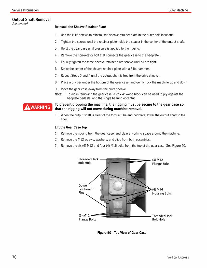
Service Information GD-2 Machine
70 Vertical Express
Output Shaft Removal(continued)
Reinstall the Sheave Retainer Plate
1. Use the M16 screws to reinstall the sheave retainer plate in the outer hole locations.
2. Tighten the screws until the retainer plate holds the spacer in the center of the output shaft.
3. Hoist the gear case until pressure is applied to the rigging.
4. Remove the non-rotator bolt that connects the gear case to the bedplate.
5. Equally tighten the three-sheave retainer plate screws until all are tight.
6. Strike the center of the sheave retainer plate with a 5 lb. hammer.
7. Repeat Steps 3 and 4 until the output shaft is free from the drive sheave.
8. Place a pry bar under the bottom of the gear case, and gently rock the machine up and down.
9. Move the gear case away from the drive sheave.
Note: To aid in removing the gear case, a 2" x 4" wood block can be used to pry against the bedplate pedestal and the single bearing eccentric.
To prevent dropping the machine, the rigging must be secure to the gear case so that the rigging will not move during machine removal.
10. When the output shaft is clear of the torque tube and bedplate, lower the output shaft to the floor.
Lift the Gear Case Top
1. Remove the rigging from the gear case, and clear a working space around the machine.
2. Remove the M12 screws, washers, and clips from both eccentrics.
3. Remove the six (6) M12 and four (4) M16 bolts from the top of the gear case. See Figure 50.
Figure 50 - Top View of Gear Case
Threaded JackBolt Hole
DowelPositioningPins
(3) M12 Flange Bolts
(4) M16 Housing Bolts
Threaded JackBolt Hole
(3) M12 Flange Bolts
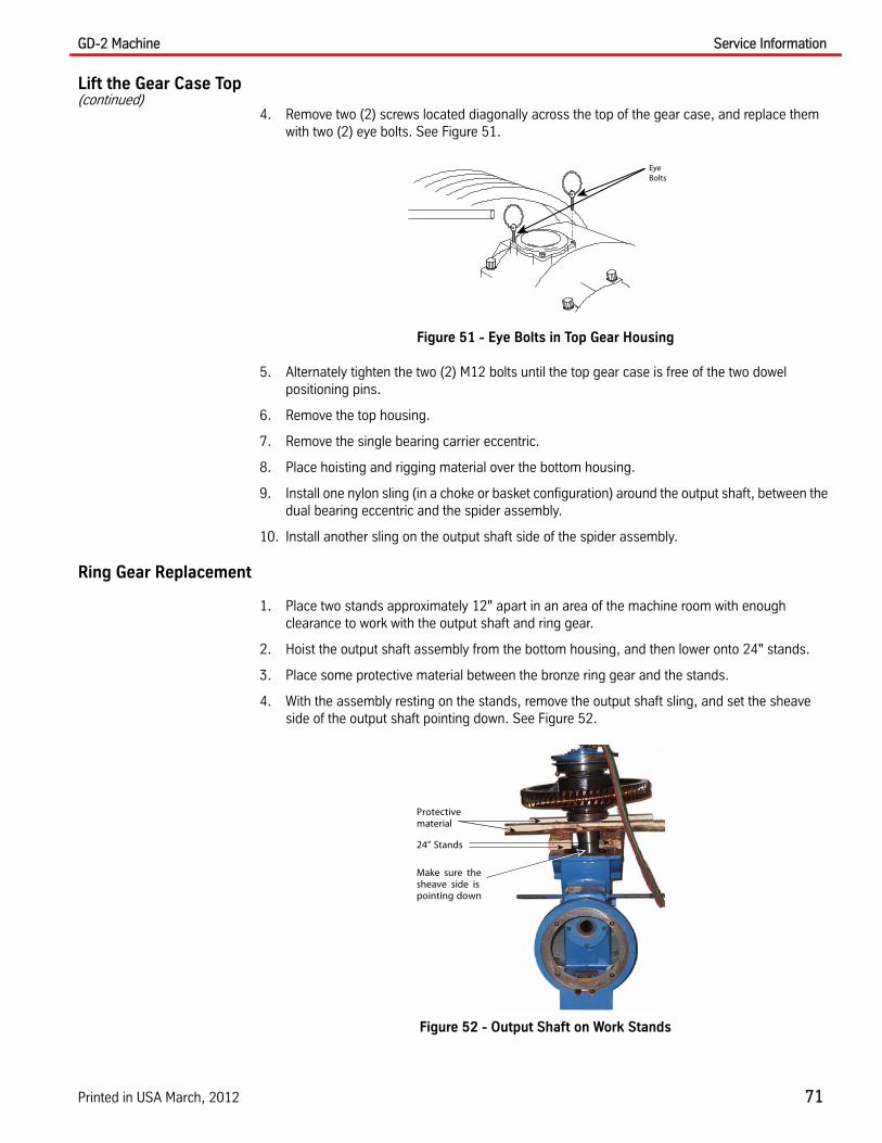
GD-2 Machine Service Information
Printed in USA March, 2012 71
Lift the Gear Case Top(continued)
4. Remove two (2) screws located diagonally across the top of the gear case, and replace them with two (2) eye bolts. See Figure 51.
Figure 51 - Eye Bolts in Top Gear Housing
5. Alternately tighten the two (2) M12 bolts until the top gear case is free of the two dowel positioning pins.
6. Remove the top housing.
7. Remove the single bearing carrier eccentric.
8. Place hoisting and rigging material over the bottom housing.
9. Install one nylon sling (in a choke or basket configuration) around the output shaft, between the dual bearing eccentric and the spider assembly.
10. Install another sling on the output shaft side of the spider assembly.
Ring Gear Replacement
1. Place two stands approximately 12" apart in an area of the machine room with enough clearance to work with the output shaft and ring gear.
2. Hoist the output shaft assembly from the bottom housing, and then lower onto 24" stands.
3. Place some protective material between the bronze ring gear and the stands.
4. With the assembly resting on the stands, remove the output shaft sling, and set the sheave side of the output shaft pointing down. See Figure 52.
Figure 52 - Output Shaft on Work Stands
Eye Bolts
24” Stands
Protectivematerial
Make sure thesheave side ispointing down

Service Information GD-2 Machine
72 Vertical Express
Ring Gear Replacement(continued)
5. Remove the six (6) 3/4” nuts, washers, and bolts that secure the ring gear to the gear flange. Note the position of the ring gear bolts, washers, and nuts because the new material is to be installed in the same position.
6. Contact the building engineer to turn off the machine room smoke detectors.
7. With a gloved hand, gently warm the gear with a torch until the gear can be lifted off the gear flange.
8. Check the mating surfaces of the new gear and the gear flange for any debris that may hinder a flush fit.
9. With a gloved hand, set the new gear with the mating side down on the gear flange. Gently warm the new gear until it drops onto the gear flange.
10. Once the gear is sitting flush, align the holes to match the gear flange (drift pins or an existing bolt can be used for alignment).
11. Allow the gear to cool completely. While the gear is cooling, remove all the old silicone and Loc-tite from all of the machine bolts and sealing surfaces.
12. When the gear has cooled completely, hand-ream the holes from the flange side up.
13. Insert and tighten the bolts, washers, and nylon insert lock nuts.
Note: It may be necessary to use the lock nut to pull the bolt through; turn the lock nut until the bolt head is flat on the gear surface. Do not hammer the bolts.
14. Torque the lock nuts to 80 ft/lb.
O-rings and Seal Replacement
1. Remove the old O-ring from behind the dual bearing eccentric. Use sandpaper or emery cloth to clean the dual bearing eccentric and gland ring of any sharp edges or burrs that may dam-age the new O-ring.
2. Add a light coating of grease to the O-ring groove in the housing. Submerge the new O-ring in oil, and stretch it over and around the dual bearing eccentric and gland ring.
3. Remove the O-ring from the single bearing eccentric carrier. Use sandpaper or emery cloth to clean the single bearing eccentric carrier of any sharp edges or burrs that may damage the new O-ring.
4. Add a light coating of grease to the O-ring groove in the housing. Submerge the new O-ring in oil, and install it on the carrier.
5. The GD-2 Machine has two styles of single bearing eccentric seals. If the machine was shipped prior to 02/01/03, and if there has been an excessive oil leak around the pedestal or sheave area, verify that Field Bulletin 04_04_02 Spider Leak.doc has been performed.

GD-2 Machine Service Information
Printed in USA March, 2012 73
O-rings and Seal Replacement(continued)
6. Determine the machine manufacturing date, and perform the following applicable procedure.
• Machines Manufactured Before 02/01/03 - A V-ring was mounted on the gear flange assembly. See Figure 53, and complete the following steps:
a. Remove the V-ring seal from the gear flange assembly (the V-ring is located just behind the output shaft ball bearing).
b. Remove any burrs or debris from the gear flange where the V-ring will be located. Remove debris from inside the surface of the single bearing eccentric carrier where the V-ring lip will be located.
c. Apply a light film of grease on the lip of the V-ring and install the new V-ring (stretch the seal over the output shaft ball bearing and seat it on the gear flange).
Figure 53 - Output Shaft with O-ring and Seal (machines manufactured before 02/01/03)
• Machines Manufactured After 02/01/03: An output shaft seal is mounted inside the eccen-tric. See Figure 54, and complete the following steps:
a. Set the eccentric carrier assembly, with the flange that sits against the machine housing, down on two (2) 2"x 4" blocks.
b. Place a 6" OD PVC pipe (approximately 10" long) into the eccentric carrier.
c. Place a 2" x 4" x 8" block across the top of the PVC pipe, and strike it with a hammer to remove the old output shaft seal.
d. Measure with a caliper, and scribe two marks 6.226"on the OD of the PVC pipe from the square end, 180° apart.
e. Lubricate the edge of the seal with a light coating of grease, and place the seal with the sealing lip down.
f. Lightly tap the new seal until it is 6.226" from the edge of the eccentric carrier.
Note: The two marks on the PVC pipe should be flush with the top of the eccentric carrier.
Figure 54 - Output Shaft with O-ring and Seal (machines manufactured after 02/01/03)
O-ringSingle Bearing Carrier
V-ring
O-ringSingle Bearing Carrier
Output Shaft Seal
Sealing lip must beturned towardthe gear
6.226
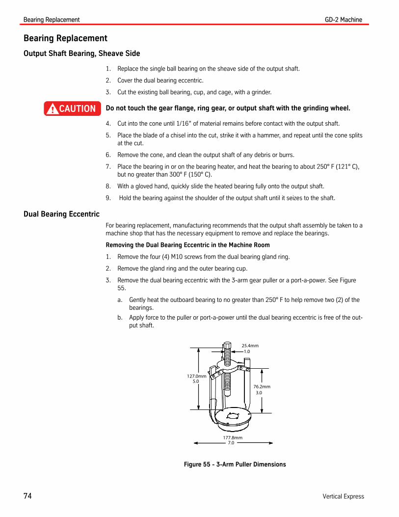
Bearing Replacement GD-2 Machine
74 Vertical Express
Bearing Replacement
Output Shaft Bearing, Sheave Side
1. Replace the single ball bearing on the sheave side of the output shaft.
2. Cover the dual bearing eccentric.
3. Cut the existing ball bearing, cup, and cage, with a grinder.
Do not touch the gear flange, ring gear, or output shaft with the grinding wheel.
4. Cut into the cone until 1/16” of material remains before contact with the output shaft.
5. Place the blade of a chisel into the cut, strike it with a hammer, and repeat until the cone splits at the cut.
6. Remove the cone, and clean the output shaft of any debris or burrs.
7. Place the bearing in or on the bearing heater, and heat the bearing to about 250° F (121° C), but no greater than 300° F (150° C).
8. With a gloved hand, quickly slide the heated bearing fully onto the output shaft.
9. Hold the bearing against the shoulder of the output shaft until it seizes to the shaft.
Dual Bearing Eccentric
For bearing replacement, manufacturing recommends that the output shaft assembly be taken to a machine shop that has the necessary equipment to remove and replace the bearings.
Removing the Dual Bearing Eccentric in the Machine Room
1. Remove the four (4) M10 screws from the dual bearing gland ring.
2. Remove the gland ring and the outer bearing cup.
3. Remove the dual bearing eccentric with the 3-arm gear puller or a port-a-power. See Figure 55.
a. Gently heat the outboard bearing to no greater than 250° F to help remove two (2) of the bearings.
b. Apply force to the puller or port-a-power until the dual bearing eccentric is free of the out-put shaft.
Figure 55 - 3-Arm Puller Dimensions
5.0
1.0
7.0
3.0
127.0mm
25.4mm
76.2mm
177.8mm

GD-2 Machine Bearing Replacement
Printed in USA March, 2012 75
Dual Bearing Eccentric(continued)
4. With the new O-ring and the interior bearing race installed, set the dual bearing eccentric back into place.
5. Insert the interior dual bearing cup into the dual bearing eccentric carrier in the correct order.
Before placing the heated bearing case on the shaft, the interior bearing cup must be in the dual bearing eccentric carrier.
6. Position the dual bearing eccentric as far down as possible to provide clearance for mounting the bearing cones onto the output shaft.
7. Place both dual bearing cones in or on the bearing heater, and heat the bearing to about 250° F (121° C), but no greater than 300°F (150°C).
8. With a gloved hand, quickly slide the heated dual bearings fully onto the output shaft. Ensure that the bearing is installed correctly. See Figure 56.
To avoid unnecessary labor, recheck the installation of the bearings. The bearings can be installed backwards.
Figure 56 - Dual Bearing Eccentric
9. Hold the cones against the shoulder of the output shaft until they seize to the shaft.
10. Allow the bearings to cool completely.
11. Install the outboard cup into the dual bearing eccentric carrier.
12. Insert the bearing gland (without its O-ring or shims), and install the four (4) bolts finger-tight.
13. While rotating the dual bearing eccentric on the output shaft, torque each bolt to 30 in/lbs.
O-ring
Bearing Cone
Shims
Eccentric DualBearing Carrier
Gland RingO-ring
BearingCup

Bearing Replacement GD-2 Machine
76 Vertical Express
Dual Bearing Eccentric(continued)
14. With a feeler gauge, measure the gap adjacent to each bolt and average the readings. See Figure 57.
Figure 57 - Feeler Gauge on Dual Bearing Gland
15. Remove the bearing gland, put on a shim pack (the thickness of the average gap plus .007" .18mm), and install the new O-ring on the bearing gland.
16. While turning the bearing gland, place it back into position and evenly torque the bolts to 13 ft/lbs.
Worm Gear Bearing Replacement
1. Run the empty car to the top floor.
2. Place the car on Inspection Operation.
3. Turn OFF, Lock, and Tag out the mainline disconnect.
4. Land the counterweight on their buffers by slowly drifting the empty car upward.
Notes:
• The car does not have to be hung to remove the gear case.
• The worm shaft bearings can be replaced in a GD-2 Machine without removing the output shaft assembly.
• The motor must be removed in order to access the brake pulley retainer.
Do not loosen the four (4) outer bolts of the drive sheave. If these bolts are removed, the sheave could fall from the sheave-bearing carrier.
5. Remove the following items:
• The brake pulley retainer
• The brake pulley
• The seal
• The thrust carriers
6. Take the worm out of the rear of the machine.

GD-2 Machine Bearing Replacement
Printed in USA March, 2012 77
Worm Gear Bearing Replacement(continued)
7. Remove the three (3) M10 hex button head screws and the brake retainer plate. See Figure 58.
Figure 58 - Arm Puller on Worm Shaft
8. Place a block of wood on the machine side of the brake pulley, and hit the wood with a hammer.
9. Slightly rotate the worm shaft after each strike of the hammer, until the brake pulley is free from the worm shaft.
10. To prevent cutting of the worm shaft seal, place tape over the worm shaft keyway.
11. Remove the M12 bolts from the shaft seal carrier and the worm shaft-bearing carrier.
12. Remove the worm shaft-bearing carrier from the machine housing.
13. To force the cup out of the housing, place a hand over the thrust bearing cup and rotate the worm shaft.
14. Remove the worm shaft seal carrier.
15. Remove the worm shaft from the machine.
16. Install a bearing puller on the thrust bearing, and remove the bearing.
17. Cut the front worm shaft bearing cage with a small grinder, and remove the cage and the roller from the bearing cone.
18. Cut into the cone until 1/16” of material remains before contact with the shaft.
19. Place a 3/4” chisel into the cut, and strike the chisel with a hammer until the cone splits.
Do not let the chisel contact the worm shaft.
20. Place new bearings in the heater, and heat the bearings to 250° F (121° C), but no greater than 300° F (150°).
Arm Puller
Brake Retainer
Bearing Cup
Seal Carrier
Worm Shaft Seal
Bearing Cone
Bearing Cone
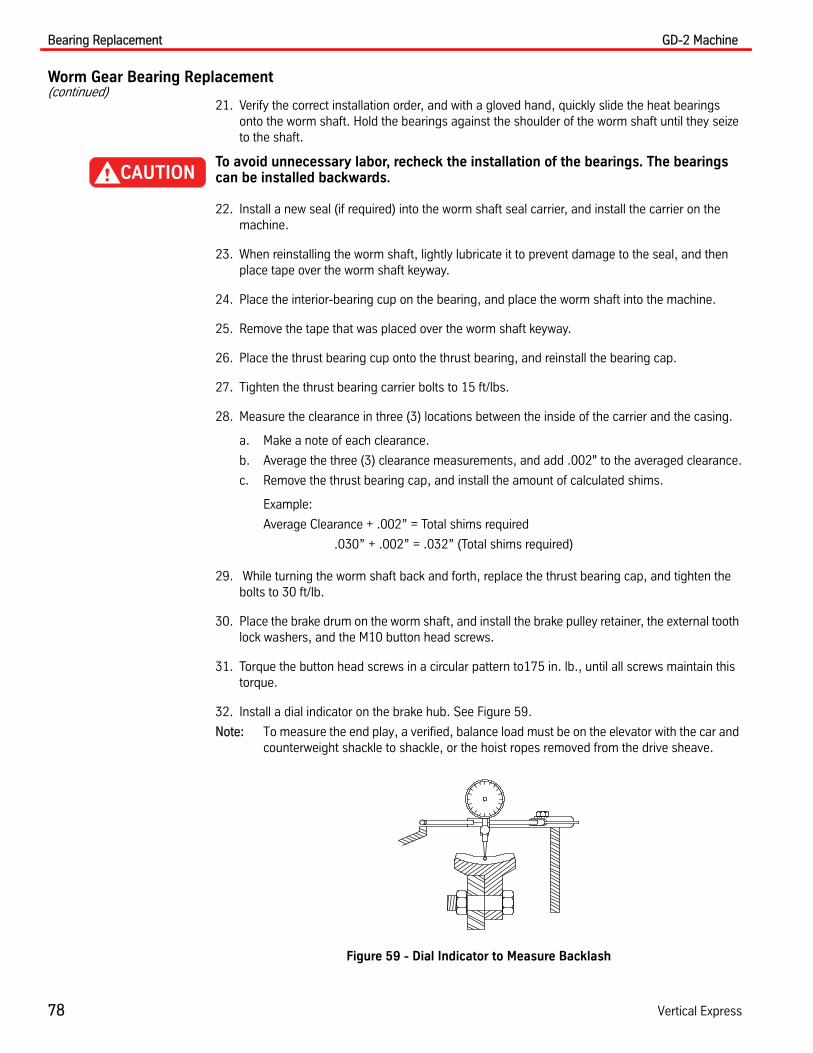
Bearing Replacement GD-2 Machine
78 Vertical Express
Worm Gear Bearing Replacement(continued)
21. Verify the correct installation order, and with a gloved hand, quickly slide the heat bearings onto the worm shaft. Hold the bearings against the shoulder of the worm shaft until they seize to the shaft.
To avoid unnecessary labor, recheck the installation of the bearings. The bearings can be installed backwards.
22. Install a new seal (if required) into the worm shaft seal carrier, and install the carrier on the machine.
23. When reinstalling the worm shaft, lightly lubricate it to prevent damage to the seal, and then place tape over the worm shaft keyway.
24. Place the interior-bearing cup on the bearing, and place the worm shaft into the machine.
25. Remove the tape that was placed over the worm shaft keyway.
26. Place the thrust bearing cup onto the thrust bearing, and reinstall the bearing cap.
27. Tighten the thrust bearing carrier bolts to 15 ft/lbs.
28. Measure the clearance in three (3) locations between the inside of the carrier and the casing.
a. Make a note of each clearance.
b. Average the three (3) clearance measurements, and add .002" to the averaged clearance.
c. Remove the thrust bearing cap, and install the amount of calculated shims.
Example:
Average Clearance + .002” = Total shims required
.030” + .002” = .032” (Total shims required)
29. While turning the worm shaft back and forth, replace the thrust bearing cap, and tighten the bolts to 30 ft/lb.
30. Place the brake drum on the worm shaft, and install the brake pulley retainer, the external tooth lock washers, and the M10 button head screws.
31. Torque the button head screws in a circular pattern to175 in. lb., until all screws maintain this torque.
32. Install a dial indicator on the brake hub. See Figure 59.
Note: To measure the end play, a verified, balance load must be on the elevator with the car and counterweight shackle to shackle, or the hoist ropes removed from the drive sheave.
Figure 59 - Dial Indicator to Measure Backlash

GD-2 Machine Bearing Replacement
Printed in USA March, 2012 79
Replace the Output Shaft
1. From the dual bearing eccentric flange, turn the hex set screws counterclockwise. Count and record the number of turns (to be used later) until the screws are flush with the flange.
2. Slide the O-ring and gland ring to the dual bearing eccentric flange.
3. Set the output shaft back down into the housing.
Note: While turning the worm shaft back and forth, the O-ring should be slightly out of the O-ring groove in the machine housing.
4. Remove the lifting choker used to lift the shaft.
5. Ensure that grease has been added to the O-ring groove in the machine housing, and that the O-rings have been oiled.
6. Smooth silicone sealer on the flange surface of the gear case.
Note: Do not put silicone sealer on any surface that will come in contact with either bearing eccentric.
7. Set the C stamp (in the flange of the eccentric) to the 12 o'clock position, with the handles between the 10 o'clock and the 11 o'clock position.
Note: The top of the gear case (toward the motor) is clockwise. The top of the case will be the 12 o'clock position.
8. To ensure backlash is present, rock the gear.
9. Carefully set the gear case cover on top of the gear case (do not damage the O-rings), and align the dowel pins back into place.
Notes:
• If the original ring gear and spider shaft are being reinstalled in the machine, set the eccentrics marks to match the machine marks.
• Before tightening the mounting bolts, make sure that there is some space between the worm shaft and the ring gear. The worm gear is at its lowest point (maximum gear clear-ance), when the eccentric handles are between the 10 o'clock and the 11 o'clock position.
10. Inspect the position of both O-rings, and move them away from the machine housing.
11. Tighten the top case mounting bolts until both case flanges just touch.
12. Push both eccentric O-rings into their grooves on the gear case.
13. Push the single and dual bearing eccentric carriers until their flanges are against the gear case.
14. Install and lightly tighten the sheave side single bearing eccentric cast clips and bolts as well as the dual bearing eccentric bolts.
15. Turn the hex set screws clockwise the number of turns recorded in Step 1.

Bearing Replacement GD-2 Machine
80 Vertical Express
Replace the Output Shaft(continued)
16. Turn the worm shaft to ensure that the worm and ring gears are not restrained.
a. If the worm gear does not turn easily, loosen the gear case flange bolts and retainer clips. Repeat this action until the worm turns easily.
b. Retighten the flange bolts, and ensure that the worm turns easily.
c. If the worm gear is still restrained, remove the gear case top and check the clearance.
d. If the worm gear is still connected with the worm shaft, move the eccentrics.
17. Tighten the top case mounting bolts to the specified torques. See Figure 60.
Figure 60 - Torques for Top Case Mounting Bolts
18. Adjust both eccentric handles until the marks on the eccentric and the marks on the gear case are aligned.
19. Rotate the worm shaft to ensure there is no binding. Adjust the handles if the worm does not move easily.
20. Tighten the retainer clips.
M16 Flange Bolts (4)Torque 175 ft. lb.
M12 Flange Bolts (6)Torque 70 ft. lb.

GD-2 Machine Bearing Replacement
Printed in USA March, 2012 81
Installing the Gear Case on the Bedplate
1. Install hoisting and rigging materials over the gear case and bedplate.
2. Attach rigging to the machine so that it will sit almost level.
3. Hoist the machine, and slide toward the pedestal until the output shaft is in the torque tube (but not engaging the drive sheave).
4. Align the drive sheave and the output keyways.
5. Slide the gear case until the output shaft is stopped by the drive sheave.
6. Install the key in the keyway. See Figure 61.
Figure 61 - Output Shaft Keyway
7. Install the drive sheave retainer and the three drive sheave retainer bolts, in the center three holes.
8. Alternately tighten the drive sheave retainer bolts until 100 ft/lb. is maintained.
9. Install the non-rotator bolt (to anchor the machine to the bedplate), and torque to 120 ft/lb.
10. Remove the rigging from the machine.
Brake Installation
1. Remove the worm shaft seal protective tape from the brake pulley keyway.
2. Install the key into the keyway.
3. Place the brake pulley retainer, locking washers, and button head screws onto the end of the worm shaft, and torque the button screws to 175 in/lbs.
4. Continue to torque the button screws until they maintain 175 in/lbs.
5. Reinstall the brake components in the reverse order of the installation.
The brake spring must be compressed to the previous used value.
Keyway
Key
Sheave Retainer Holes

Bearing Replacement GD-2 Machine
82 Vertical Express
Motor Installation
1. Hoist the motor, reinstall, and tighten the four (4) 5/8" flat, lock washers, and screws.
2. Rotate the armature coupling until the keyway is approximately 180° from the brake pulley key-way.
3. Rewire the motor and encoder (if removed).
4. Use cushions, eternal tooth lock washers, and nuts to install the eight (8) brake pulley shoulder bolts.
5. Adjust the gears. See “End Thrust Test and Adjustment” on page 53.
6. Verify the motor parameters. See the TAC50-xx Controller manual (or other mfg. for all non-Vertical Express Controllers).
• MFC
• MSF or RSF
• KVI
• KFP
• MTP or number of motor poles
• LPF
• NCF
• Auto Tune TAC 50-xx
7. Verify that all field bulletins for the GD-2 Machine have been completed.

GD-2 Machine Troubleshooting Chart
Printed in USA March, 2012 83
Troubleshooting Chart
Problem Cause
Brake is not properly picking or dropping Worn parts
Improper adjustment
Improper maintenance
Bad power supply
Excessive gear box heat Not enough backlash
Low or contaminated oil
Not enough worm end play
High-duty cycle
Brush noise or sparking Incorrect or wrong length brushes
Commutator damaged
Excessive current
Sheave noise Improper rope tension
Sheave wear
Rope wear
Machine misaligned
Motor noise Improper motor parameters
Misaligned motor
Bent brake coupling shoulder bolts
Brake coupling cushion pinched
Worn motor bearing or damaged
Oil leaking Damaged O-ring
Damaged seal
Loose screws
Ride quality Gear alignment
Lack of backlash
Excessive backlash
Incorrect end play
Isolation pads installed incorrectly or missing
Rope tension
Incorrect drive parameters
Poor car or counterweight rail alignment
Improper roller guide set-up
Isolation broken between the cab/platform and car sling
Defective encoder
Machine bearings worn
Motor bearings worn

Replacement Parts GD-2 Machine
84 Vertical Express
Replacement Parts
GD-2 Machine (4501AM)
14
9
2
11
6
3
7
8
5
15
16
12
17
18
13
19
10
14
20
NOTE: Required onmachines shippedbefore 02/01/03

GD-2 Machine GD-2 Machine (4501AM)
Printed in USA March, 2012 85
GD-2 Machine (4501AM)(continued)
ITEM PART NO. PRINT NO. DESCRIPTION
1 436AG1 Gear, D-65
2 436AG2 Gear, S-57
3 436AG3 Gear, D-83
4 70378 Gear Locknut, NHL, .75 U
5 100508 Screw, CSH, .75 x 2.5 UE, Gear Retaining
6 110910 Drive Sheave
7 732AN1 Seal, Sheave Carrier
8 142BB1 Bearing, Cone, Sheave Carrier
9 142BC1 Bearing, Cup, Sheave Carrier
10 781BA1 Bearing, Spacer, Sheave Carrier
11 760AR1 Sheave Bearing Shims, .005
12 760AR2 Sheave Bearing Shims, .007
13 760AR3 Sheave Bearing Shims, .020
14 760AR4 Sheave Bearing Shims, .060
15 732AN2 Seal, Sheave Bearing Retainer
16 9833511 320AJ1 Gear Inspection Cover
17 142BE1 Bearing, Ball, Output Shaft
18 254AV2 Carrier, Single Bearing Eccentric
19 732BM1 Seal, Output Shaft
20 142AE1 Bearing, Cup, Dual Bearing, Output Shaft
32
22
23
24
25
21
3126
28
29
3027
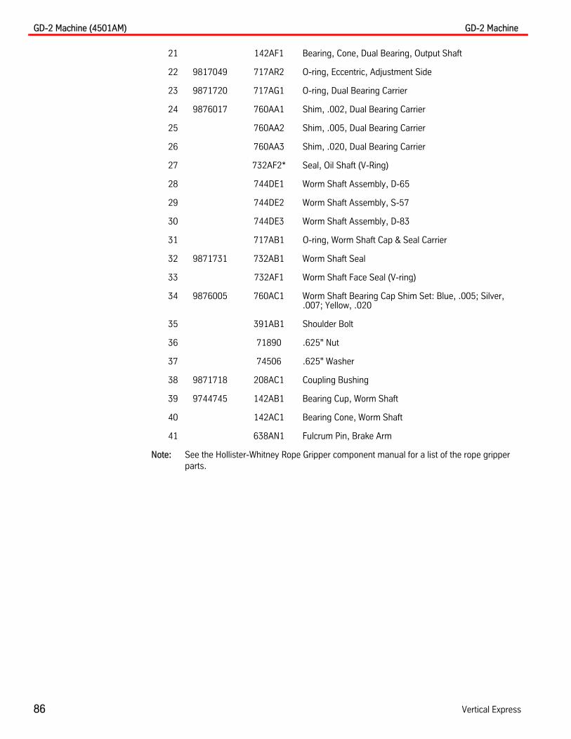
GD-2 Machine (4501AM) GD-2 Machine
86 Vertical Express
21 142AF1 Bearing, Cone, Dual Bearing, Output Shaft
22 9817049 717AR2 O-ring, Eccentric, Adjustment Side
23 9871720 717AG1 O-ring, Dual Bearing Carrier
24 9876017 760AA1 Shim, .002, Dual Bearing Carrier
25 760AA2 Shim, .005, Dual Bearing Carrier
26 760AA3 Shim, .020, Dual Bearing Carrier
27 732AF2* Seal, Oil Shaft (V-Ring)
28 744DE1 Worm Shaft Assembly, D-65
29 744DE2 Worm Shaft Assembly, S-57
30 744DE3 Worm Shaft Assembly, D-83
31 717AB1 O-ring, Worm Shaft Cap & Seal Carrier
32 9871731 732AB1 Worm Shaft Seal
33 732AF1 Worm Shaft Face Seal (V-ring)
34 9876005 760AC1 Worm Shaft Bearing Cap Shim Set: Blue, .005; Silver, .007; Yellow, .020
35 391AB1 Shoulder Bolt
36 71890 .625" Nut
37 74506 .625" Washer
38 9871718 208AC1 Coupling Bushing
39 9744745 142AB1 Bearing Cup, Worm Shaft
40 142AC1 Bearing Cone, Worm Shaft
41 638AN1 Fulcrum Pin, Brake Arm
Note: See the Hollister-Whitney Rope Gripper component manual for a list of the rope gripper parts.

GD-2 Machine Output Shaft Assembly (744DH1)
Printed in USA March, 2012 87
Output Shaft Assembly (744DH1)Shipped before 02/01/03
ITEM PART NO. PRINT NO. DESCRIPTION
1 744CF1 Shaft, Sub-Assembly, Output, 744DG1
2 142AE1 Bearing, Cup
3 142AF1 Bearing, Cone
4 142BE1 Bearing, Ball
5 717CH1 Ring, Gland
6 9817049 717AR2 O-ring
7 254AT1 Carrier, Dual Bearing, Eccentric (GD-2)
8 438AB1 Bearing, Gland (GD-0/GD-1)
9 405AG2 Screw, FS, CSH, M10 x 35mm
10 408AG2 Washer, FS, LWH, M10 Z
11 9876017 760AA1 Shim, .002
12 760AA2 Shim, .005
13 760AA3 Shim, .020
14 9871720 717AG1 O-ring
15 254AV1 Carrier, Single Bearing, Eccentric
16 9817049 717AR2 O-ring
17 732AF2 V-ring
X
33.752
41
3
56
7
8
10
2
9
12
14
13 11
16 15
18
18
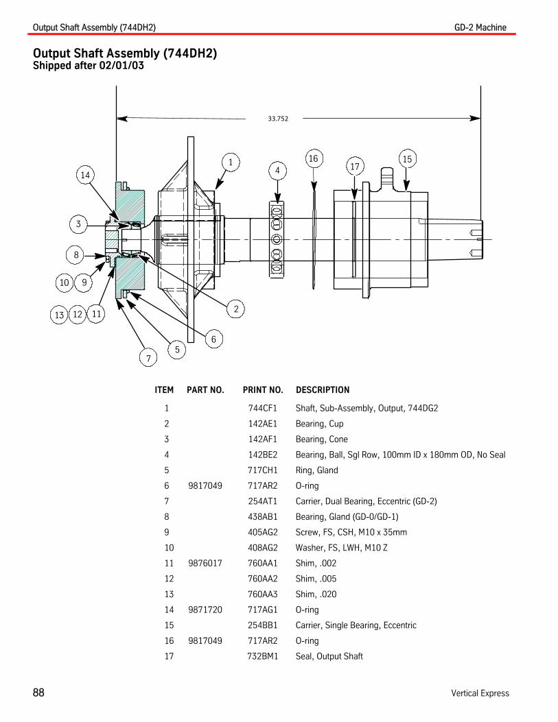
Output Shaft Assembly (744DH2) GD-2 Machine
88 Vertical Express
Output Shaft Assembly (744DH2)Shipped after 02/01/03
ITEM PART NO. PRINT NO. DESCRIPTION
1 744CF1 Shaft, Sub-Assembly, Output, 744DG2
2 142AE1 Bearing, Cup
3 142AF1 Bearing, Cone
4 142BE2 Bearing, Ball, Sgl Row, 100mm ID x 180mm OD, No Seal
5 717CH1 Ring, Gland
6 9817049 717AR2 O-ring
7 254AT1 Carrier, Dual Bearing, Eccentric (GD-2)
8 438AB1 Bearing, Gland (GD-0/GD-1)
9 405AG2 Screw, FS, CSH, M10 x 35mm
10 408AG2 Washer, FS, LWH, M10 Z
11 9876017 760AA1 Shim, .002
12 760AA2 Shim, .005
13 760AA3 Shim, .020
14 9871720 717AG1 O-ring
15 254BB1 Carrier, Single Bearing, Eccentric
16 9817049 717AR2 O-ring
17 732BM1 Seal, Output Shaft
33.752
41
3
56
7
8
10
2
9
12
14
13 11
1617
15

GD-2 Machine Brake Assemblies
Printed in USA March, 2012 89
Brake Assemblies
ITEM PART NO. PRINT NO. DESCRIPTION
1 205BN1 Brake Arm Assembly, Sheave Side
2 205BN2 Brake Arm Assembly, Adjustment Side
3 559AA3 Brake Lining
4 711CF1 Brake Spring Washer (tube end)
5 9875827 75826 Brake Spring
6 9800311 100014 Brake Spring Washer
7 405AT2 Stroke Adjustment Screw
8 779AB5 Solenoid Assembly
9 779AG3 Solenoid Assembly
10 402AB2 Stroke Adjustment Locknut, NHJ, M12 U
11 402AF1 Spring Adjustment Locknut, NHL, M16 Z
12 402AC1 Spring Adjustment Locknut, Sheave Side, NHL, M12
13 402AC2 Spring Adjustment Locknut, Adjustment Side, NHL, M24
Single Solenoid 4503AD1 Dual Solenoid 4503AD2
9
11
7
6
3
2
1 1
2
3
4
5
8
12
13
10

Single Solenoid Assembly (140V) 799AG3 GD-2 Machine
90 Vertical Express
Single Solenoid Assembly (140V) 799AG3
ITEM PART NO. PRINT NO. DESCRIPTION
1 778AL1 Plate, Rear
2 9815867 765AC3 Sleeve, Solenoid
3 9815879 181AH1 Armature Assembly
4 28327 Coil, 140V
28326 Coil, 220V
5 26329 Shell
6 778AJ1 Plate, Front
7 110464 Screw
8 700407 Washer
9 9700407 700564 Nut
10 72816 Dust Seal
10
Isometric View
2
3
4567 91 8

GD-2 Machine Dual Solenoid Assembly (140V) 799AB5
Printed in USA March, 2012 91
Dual Solenoid Assembly (140V) 799AB5
ITEM PART NO. PRINT NO. DESCRIPTION
1 196FL2 Bracket, Solenoid Housing
2 459AC2 Handle, Emergency Extension
3 405AG1 Screw, FS, CSH, M10 x 25mm Lg. Z
4 165DP1 Plate, Front Machined, GD-1
5 779AD1 Solenoid Armature Assembly, GD-1
6 765AC2 Sleeve, Solenoid
7 280AA1 Coil 140V DC
8 408AG2 Washer, FS, LWHR, M10 Z
9 781AG1 Spacer, Nylon
10 459AC2 Handle, Emergency Cam
11 717AY1 O-ring 2.250 x .500
12 408AE1 Washer, FS LWET M10
13 459AJ1 Handle, Brake, Removable
12
3
4
5
6
7
8
9
10
11
12 13

Encoder/Motor Coupling (AC Motor Shown) GD-2 Machine
92 Vertical Express
Encoder/Motor Coupling (AC Motor Shown)
ITEM PART NO. PRINT NO. DESCRIPTION
1 590CC15 Motor, 460VAC, 1180RPM, 50HP
590CC14 Motor, 460VAC, 1180RPM, 40HP
2 309AR1 Armature Coupling
3 391AB1 FS, Shoulder Bolt
4 405BE1 Set Screw, SSHS (MX10 x 10)
5 74506 LWET Washer .625"
6 71890 Nut, .625"
7 9871718 208AC1 Coupling Bushing
8 9817610 373AX1 Encoder, 2048 CPR w/hardware
9 396AV1 Screw, SPABS #6, 138 x .500Z
10 482BP2 Encoder Housing
11 70395 Screw, CSH .250-20 UNC x .750Z
12 74599 Washer, LWET.250Z
13 802BT2 Support, Encoder, Non-Rotator
14 700682 Screw, STPFP #10, .190 x .500Z
15 700393 Washer, FWA #10, .190
16 392CB1 Square Head Grommet Nut, nylon
1Encoder, Front View Motor, Side View
910
12
167
5
6
2
4
13
3
8
9
11
1514

GD-2 Machine Brake Switch
Printed in USA March, 2012 93
Brake Switch
ITEM PART NO. PRINT NO. DESCRIPTION
1 68415 Switch, Micro BZ2RG1-A2
2 77551 Cover, Junction Box
3 546AG1 Junction Box, 4.0 x 2.125 x 1.5
4 196JL1 Bracket, "Z" Switch/Actuator
5 45241 Spring
6 45239 Plunger
7 26739 Screw, Adjusting
8 45240 Retainer, Plunger
9 392BA1 Washer, FS. ENG., Cupped, 500 SE
10 9700407 700564 Nut, FS, NH, .375 Z
1
2
3
4
5
6
7
4
1098
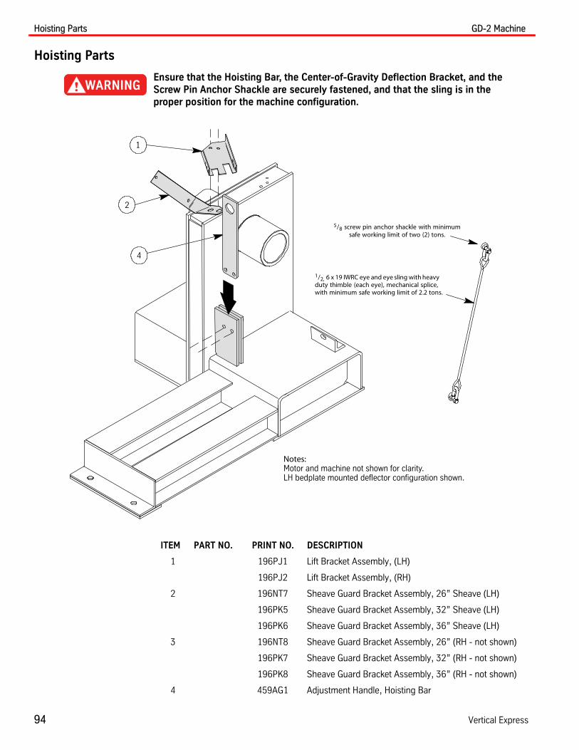
Hoisting Parts GD-2 Machine
94 Vertical Express
Hoisting Parts
Ensure that the Hoisting Bar, the Center-of-Gravity Deflection Bracket, and the Screw Pin Anchor Shackle are securely fastened, and that the sling is in the proper position for the machine configuration.
ITEM PART NO. PRINT NO. DESCRIPTION
1 196PJ1 Lift Bracket Assembly, (LH)
196PJ2 Lift Bracket Assembly, (RH)
2 196NT7 Sheave Guard Bracket Assembly, 26” Sheave (LH)
196PK5 Sheave Guard Bracket Assembly, 32” Sheave (LH)
196PK6 Sheave Guard Bracket Assembly, 36” Sheave (LH)
3 196NT8 Sheave Guard Bracket Assembly, 26” (RH - not shown)
196PK7 Sheave Guard Bracket Assembly, 32” (RH - not shown)
196PK8 Sheave Guard Bracket Assembly, 36” (RH - not shown)
4 459AG1 Adjustment Handle, Hoisting Bar
1/2, 6 x 19 IWRC eye and eye sling with heavyduty thimble (each eye), mechanical splice,with minimum safe working limit of 2.2 tons.
1
2
4
5/8 screw pin anchor shackle with minimumsafe working limit of two (2) tons.
Notes:Motor and machine not shown for clarity.LH bedplate mounted deflector configuration shown.


Vertical Express
P.O. Box 2019 Memphis, TN 38101 Tel: (866) 448-3789 (toll-free) Fax: (901) 261-1807 www.verticalxpress.comAll illustrations and specifications are based on information in effect at the time of publication approval. Vertical Express reserves the right to changespecification or designs and to discontinue items without prior notification or obligation. v.Y.m. Copyright © 2012 Vertical Express Elevator