gcrc 2018 presentation (04)이제명
TRANSCRIPT

GCRC-SOP 8th Year International Workshop
Project 2-4
1Project 2-4 : Performance Evaluation and Application Technology in Extreme Environment
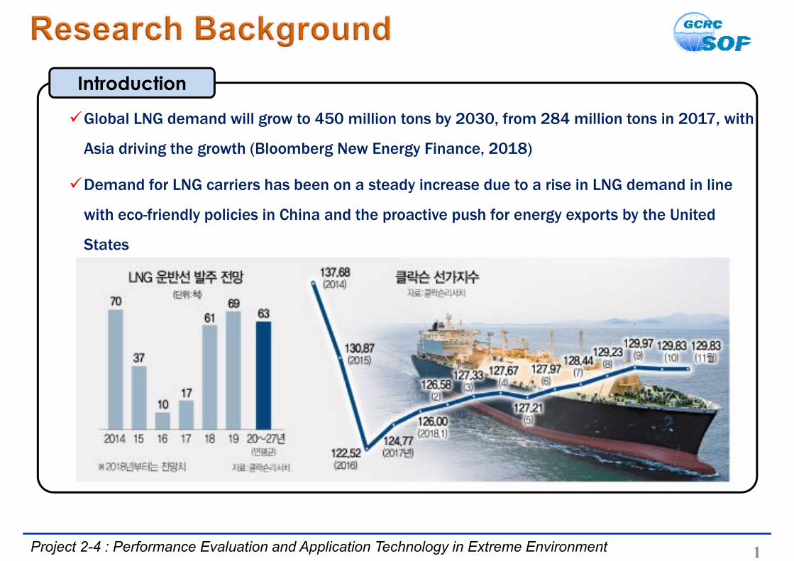
Global LNG demand will grow to 450 million tons by 2030, from 284 million tons in 2017, with
Asia driving the growth (Bloomberg New Energy Finance, 2018)
Demand for LNG carriers has been on a steady increase due to a rise in LNG demand in line
with eco-friendly policies in China and the proactive push for energy exports by the United
States
Introduction
2
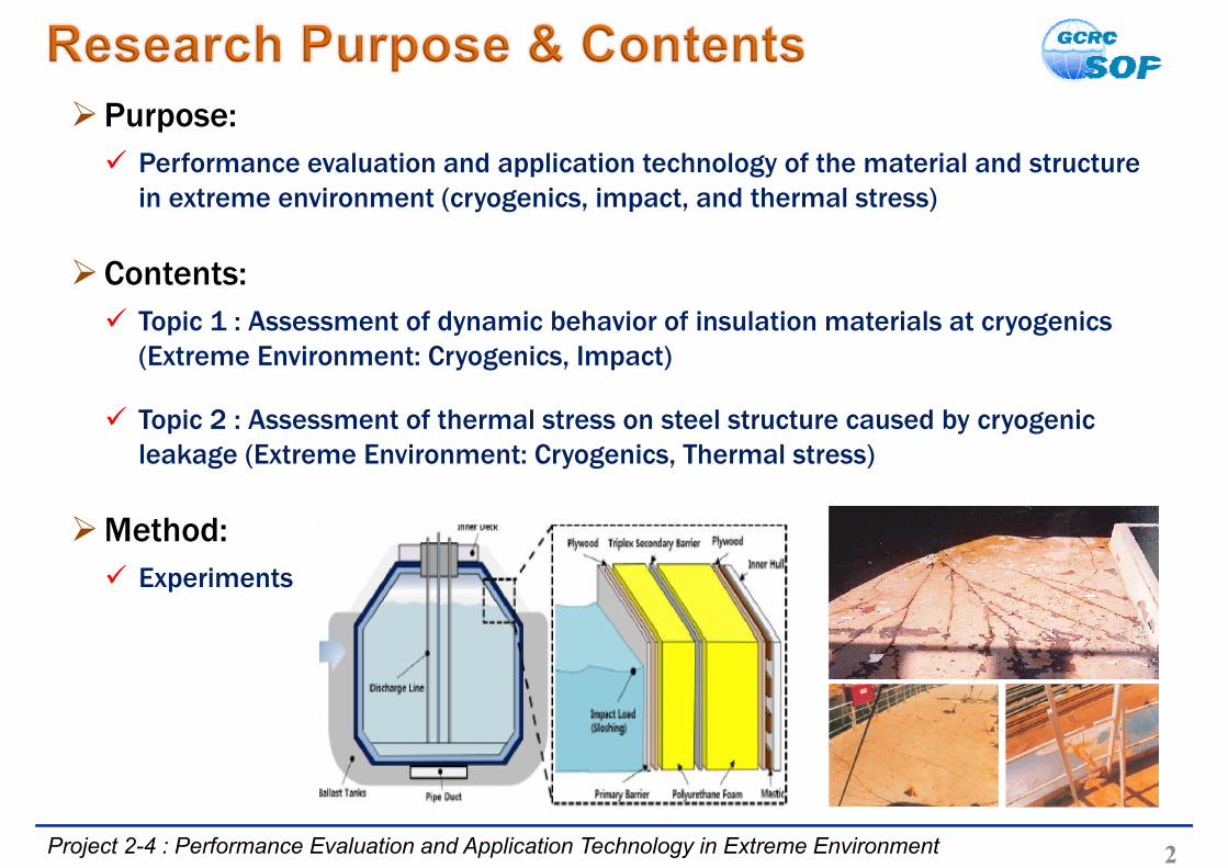
Purpose: Performance evaluation and application technology of the material and structure
in extreme environment (cryogenics, impact, and thermal stress)
Contents: Topic 1 : Assessment of dynamic behavior of insulation materials at cryogenics
(Extreme Environment: Cryogenics, Impact)
Topic 2 : Assessment of thermal stress on steel structure caused by cryogenic leakage (Extreme Environment: Cryogenics, Thermal stress)
Method: Experiments
Project 2-4 : Performance Evaluation and Application Technology in Extreme Environment

Results of Topic 1

Project 2-4 : Performance Evaluation and Application Technology in Extreme Environment
Research background
• Sloshing impact loads can lead to defect on the insulation system
• Defected insulation system arise heat penetration into inner cargo hold
4
Sloshing & hydrostatic pressure
Cryogenics (-163°C)
Primary Barrier
Plywood
(R)PUF
Triplex
(R)PUF
PlywoodMastic
LNG Carrier
Cargo Containment System
Extreme Environment

• PUF has a closed cell structure with a high compressive strength,
leakage resistance, a low density, and low thermal conductivity
• Mechanical strength and thermal conductivity of the PUF are
significantly affected by its own density state
5Project 2-4 : Performance Evaluation and Application Technology in Extreme Environment
Introduction
• Investigation of density dependent mechanical and thermal
characteristics of PUF under impact loading condition
• Investigation of optimum density condition of PUF
Research Goal
• Material : Polyurethane Foam (PUF) (blowing agent: HFC-245fa)
• Density : 90, 113, 134, 150, and 180 kg/m3
• Test temp. : 20 and -163°C
• Impact energy : 110 J
Conditions

• Fabrication of density-dependent PUF using polyol system,
Isocyanate, and blowing agent
• Polyol system : Isocyanate : blowing agent = 100 : 116 : x
6Project 2-4 : Performance Evaluation and Application Technology in Extreme Environment
Manufacturing process of PUF in lab scale
HEAT ~~~~~~~
RISINGMIXING
AB A : POLYOL SYSTEM
B : ISOYANATE + HFC‐245fa
POLYURETHAE FOAM4500RPM
Material Preparation
7Project 2-4 : Performance Evaluation and Application Technology in Extreme Environment
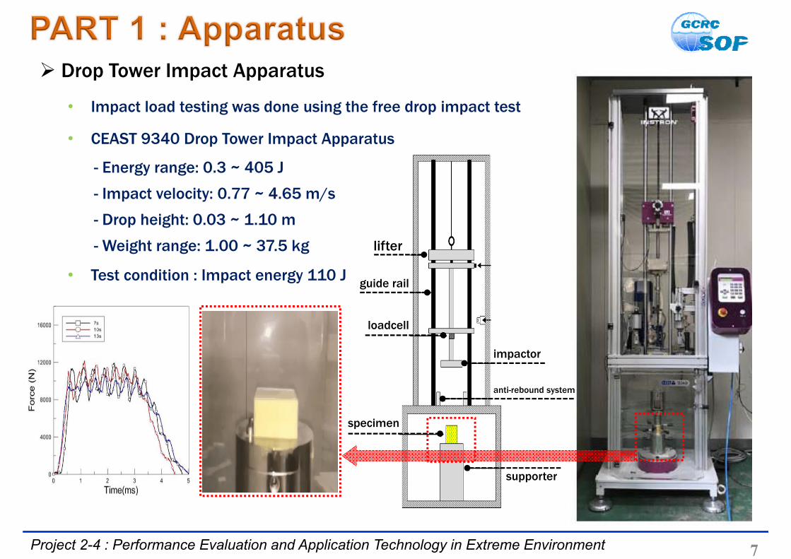
Drop Tower Impact Apparatus
• Impact load testing was done using the free drop impact test
• CEAST 9340 Drop Tower Impact Apparatus
- Energy range: 0.3 ~ 405 J
- Impact velocity: 0.77 ~ 4.65 m/s
- Drop height: 0.03 ~ 1.10 m
- Weight range: 1.00 ~ 37.5 kg
• Test condition : Impact energy 110 J guide rail
loadcell
specimen
lifter
impactor
anti-rebound system
supporter

8Project 2-4 : Performance Evaluation and Application Technology in Extreme Environment
Density dependent SS Curve(110J_-163℃)
Mechanical Results
• Yield strength, the end of initial elastic response, increases with increase in strain rate
• Up to the onset of densification dynamically deformed PUF is capable of high energy
absorption
• In cryogenic temperature, peak force and stress fluctuation increased as the cells get
stiffer than room temperature
Comparison static load with dynamic load

9Project 2-4 : Performance Evaluation and Application Technology in Extreme Environment
Microstructural Results
• Generally cells that consist of PUF are smaller and dense in high-density PUF, resulting in
small deformation and high peak force in elastic region
• As the density of PUF increase, size of cell decrease resulting in high thermal conductivity
90kg/m3 113kg/m3 134kg/m3 151kg/m3 180kg/m3
Density(kg/m3)
Thermal conductivity(W/mK)
90 0.02471
113 0.02588
134 0.02709
151 0.03012
180 0.03421

• Glass fiber reinforced polyurethane foam (RPUF) is produced by
adding glass fiber to improve the mechanical performance of PUF
• Necessity of investigation of mechanical response of insulation
material by low energy repetitive impact load
10Project 2-4 : Performance Evaluation and Application Technology in Extreme Environment
Introduction
• Effects of repetitive impact loads on mechanical characteristics of
reinforced polyurethane foam (RPUF)
• Performance degradation of RPUF owing to repeated impact loads
Research Goal
• Material : glass fiber-reinforced polyurethane foam (RPUF)
• Density : 120 kg/m3 (15 wt% fiber-glass)
• Test temp. : 20°C
• Impact energy : 2.39, 3.07, and 3.75 J
Conditions

11Project 2-4 : Performance Evaluation and Application Technology in Extreme Environment
Velocity-time history in accordance with the impact energy and the repetitive
3.75 J
Mechanical Results
• Impact velocity-time history was investigated according to the impact condition
• Initial velocity, rebound velocity, and acceleration increased with the increase of
impact energy
• With the repetitive impact, rebound velocity and acceleration decreased
2.39 J3.07 J3.75 J

12Project 2-4 : Performance Evaluation and Application Technology in Extreme Environment
2.39 J 3.07 J 3.75 J
Force time history of RPUF specimen under various impact condition
Mechanical Results
• Force time history in accordance with the impact energy and the number of repetitions
• Under the repetitive impact of 2.39 J, almost no change in force time history
• Maximum force decreased and duration increased under the repetitive impact of 3.75 J

13Project 2-4 : Performance Evaluation and Application Technology in Extreme Environment
Displacement/force/deformation under repetitive impact
Mechanical Results
• Quantitative evaluation of impact performance degradation by impact energy and the
number of repetitions
• Under 3.75 J, Maximum force 13.4% decreased, displacement 40.2% increased
• Plastic deformation was observed only at 80th impact of 3.75 J (Approx. 2%)
2.39 J3.07 J3.75 J
2.39 J3.07 J3.75 J
2.39 J3.07 J3.75 J

• Composites used in LNG cargo containment system consist of PUF,
plywood, and epoxy resin as an adhesive between PUF and plywood
• Additional enhancement through absorption energy is necessary for
impact loading against LNG sloshing
14Project 2-4 : Performance Evaluation and Application Technology in Extreme Environment
Introduction
• Dynamic response of specimens fabricated from PUF, plywood, and
epoxy resin with varying weight fractions of embedded glassbubble
• Investigation of glassbubble wt% dependent mechanical and
thermal characteristics of PUF-plywood under impact load.
Research Goal
• Material : PUF-plywood (resin : epoxy with glassbubble)
• Glassbubble (wt%) : 0, 10, and 20
• Test temp. : 20 and -163°C
• Impact energy : 30 J
Conditions
Polyurethane foam
Epoxy resin
Plywood- Size = 50 × 50 mm2
- Thickness = 7.19 mm- Density = kg/m3
- Lamina = 5 layers

15Project 2-4 : Performance Evaluation and Application Technology in Extreme Environment
Material Preparation
• Polyurethane foam is made of POLYOL + ISOCYANATE + Agent Blowing in accordance
with weight fraction of 1000:1160:50
• Epoxy resin with hollow glassbubble is physically mixed about 30min and the
ultrasonic dispersion of 20kHz use about 30min
16Project 2-4 : Performance Evaluation and Application Technology in Extreme Environment
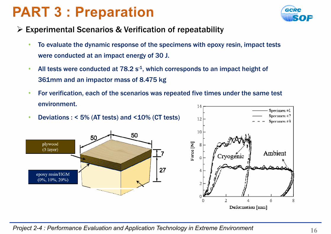
Experimental Scenarios & Verification of repeatability
• To evaluate the dynamic response of the specimens with epoxy resin, impact tests
were conducted at an impact energy of 30 J.
• All tests were conducted at 78.2 s-1, which corresponds to an impact height of
361mm and an impactor mass of 8.475 kg
• For verification, each of the scenarios was repeated five times under the same test
environment.
• Deviations : < 5% (AT tests) and <10% (CT tests)
17Project 2-4 : Performance Evaluation and Application Technology in Extreme Environment
Microstructural Results
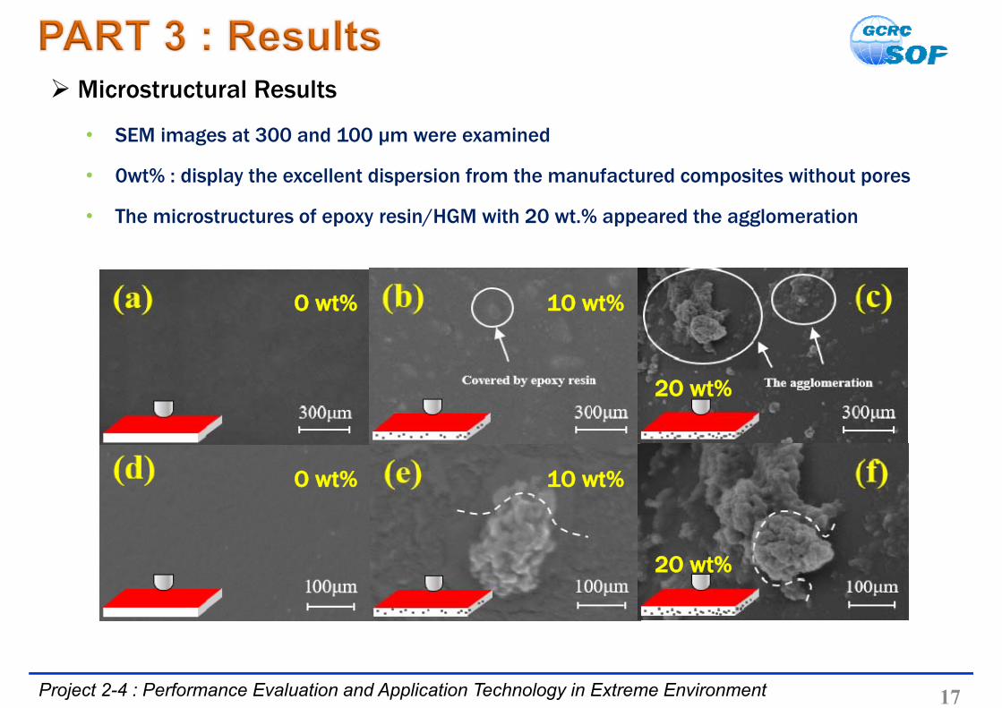
• SEM images at 300 and 100 μm were examined
• 0wt% : display the excellent dispersion from the manufactured composites without pores
• The microstructures of epoxy resin/HGM with 20 wt.% appeared the agglomeration
O wt% 1O wt%
O wt% 1O wt%
2O wt%
2O wt%

18Project 2-4 : Performance Evaluation and Application Technology in Extreme Environment
Mechanical Results
• The fluctuation in force-deformation is clearly reduced with further content of HGM.
• Dynamic relationship at cryogenic temperature shows strain hardening.
• In contrary, the relationship at ambient temperature shows strain softening.

Results of Topic 2

20Project 2-4 : Performance Evaluation and Application Technology in Extreme Environment
IEA Energy Outlook, 2017
Research background
Increase of demand on LNG carrier, LNG bunkering, FSRU, etc.
• 29 FSRUs currently in operation worldwide and additional 14 FSRUs until 2022
(Westwood Global Energy, 2017)
Cryogenic spill can be significant problem to personnel and assets
• Cryogenic burns, asphyxiation, steel embrittlement, NG cloud, etc. (Lloyd’s Register, 2015)
• LNG vessel and LNG fueled ship have the same problem
Representative accident of LNG leakage

Project 2-4 : Performance Evaluation and Application Technology in Extreme Environment
Research background
Methods to prevent undesirable accident from LNG spill
• Cryogenic spill protection(CSP) coating application
• CFD-based estimation of cryogenic fluid spill hazard area
• Cryogenic spill experiment and structural numerical analysis
Securing structural integrity from understanding cryogenic behavior of hull steel → Top Priority
Database for damage assessment for cryogenic fluid leakage on hull structure
21
Cryogenic Spill Protection coating Deck Spill simulation LNG internal spill simulation

22Project 2-4 : Performance Evaluation and Application Technology in Extreme Environment
Experimental setup of the liquefied nitrogen spill
Test method
Investigation of the effect of cryogenic spill of steel plate with initial defect
Polyurethane cooling trough installed to divide the spill area
Cryogenic fluid : Liquid nitrogen(LN2)
• LN2(-196°C) was selected considering lower temperature and safety than LNG(-163°C).
Experimental equipment
• The strain gauge measures the thermal stress of the steel plate where deformation occurs
• DAQ(Data aquisition) records strain on steel plate in real time
Experimental equipment; (a) strain gauge (b) thermocouple(c) Cyanoacrylate (CN) adhesive (d) data aquisition
(a) (b)
(c) (d)

23Project 2-4 : Performance Evaluation and Application Technology in Extreme Environment
Pre-notched defect
intermittent welding defect
Test method
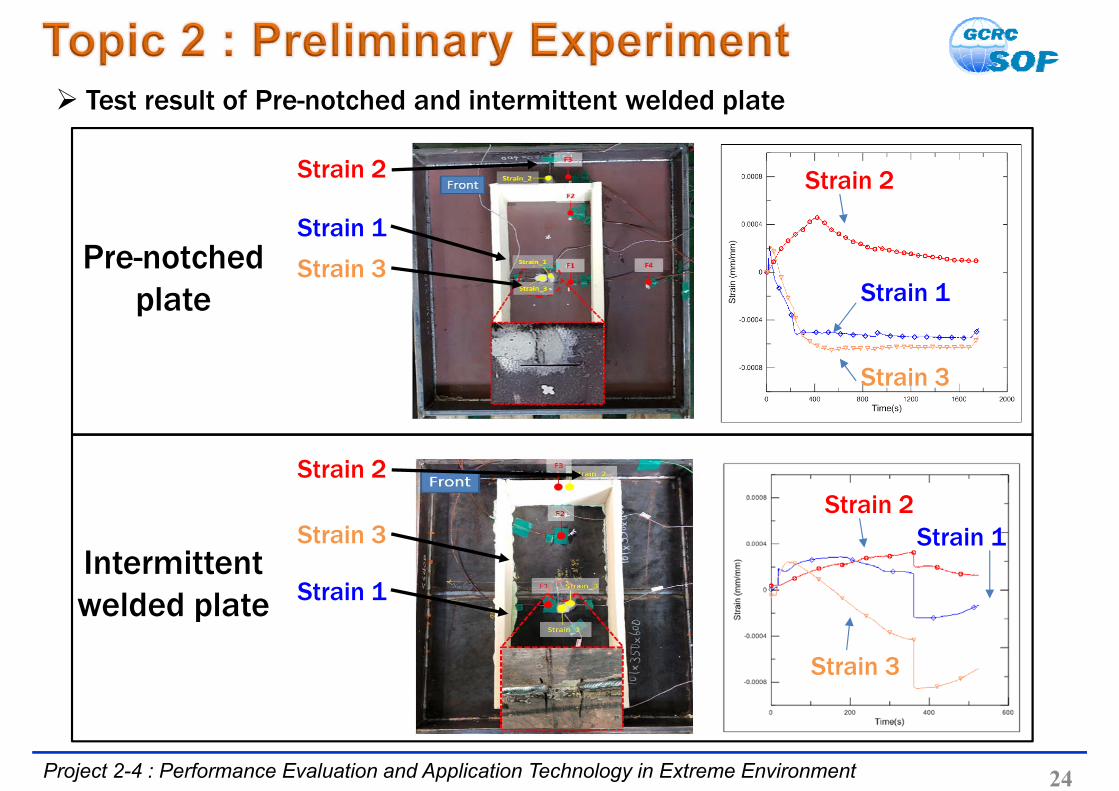
Frist scenario: Pre-notched plate (SS400)
• Plate thickness: 8T / Initial crack length: 40mm
Second scenario: intermittent welded plate (SS400)
• Plate thickness: 10T / Defect welding length: 20mm
cooling trough and gauge attachment location
24Project 2-4 : Performance Evaluation and Application Technology in Extreme Environment
Test result of Pre-notched and intermittent welded plate
Pre-notchedplate Strain 1
Strain 2
Strain 3
Strain 2Strain 1
Strain 3
Strain 1
Strain 3
Strain 2
Strain 1
Strain 3
Strain 2
Intermittentwelded plate

25Project 2-4 : Performance Evaluation and Application Technology in Extreme Environment
Plate type - AH36
Thickness – 6mm
Welding – Flux Cored Arc Welding(FCAW) method
• Automatic welding to improve the penetration defect (Over 90% use in shipbuilding industry)
Specimen Type Selection
Initial defect condition on the plate is excluded.
Welding condition is considered.
• Focusing on the center part of the weld directly affected by the cryogenic temperature
Modification of Test Condition
Crack propagation of intermittent welded plate

Steel type: AH36 Length: 500mm Width: 500mm
26Project 2-4 : Performance Evaluation and Application Technology in Extreme Environment
Test specimen and equipment
Specimen Preparation
1
2
3
4
5
6
78 Welding method: FCAW Welding passes: 3 Root gap: 60o (4mm) Root face: 60o (2mm) Welding rod: E71T-1C (1.4mm) Ceramic backing: U type (6mm)
Upper jigLower jig
Automatic welding machine
: Strain gage point
Minimize weld start and end defects Ensure safety by preventing welding crack
Insulation type: Polyurethane foam Boundary range : Partial

27Project 2-4 : Performance Evaluation and Application Technology in Extreme Environment
Constraint of AH36 Steel and welding (FCAW)
• Cooling at ambient temperature during 1 day to eliminate the effect of time after welding
Selection of spill area and measurement site and installation
• Liquid nitrogen spill for 20 minutes
Test process for cryogenic spill
Methodology
LN2 Spill (20min) Boiling Complete vaporization

28Project 2-4 : Performance Evaluation and Application Technology in Extreme Environment
Thermal strain at each point located on the steel plate (AH36)
1
2
3
4
Y
X
Analysis of thermal strain (inside boundary)
• Compressive strain mainly occurs at internal part of the boundary
• At both end points(location 2, 3), strain is higher than at the center
• Strain difference due to distance from weld line is not evident
• Initial over-cooling causes abrupt tensile thermal stress
-------- x-axis ------- y-axis
Leakage Test Results
2 3 41
29Project 2-4 : Performance Evaluation and Application Technology in Extreme Environment
5
6
78
Y
X
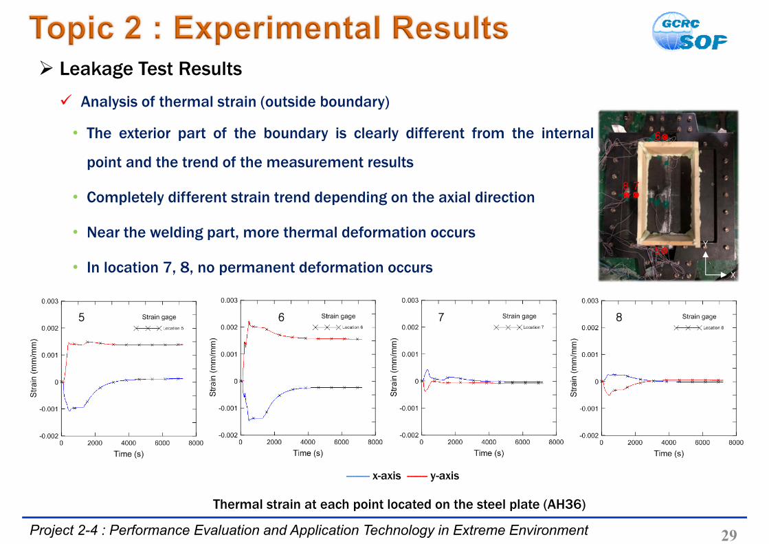
Analysis of thermal strain (outside boundary)
• The exterior part of the boundary is clearly different from the internal
point and the trend of the measurement results
• Completely different strain trend depending on the axial direction
• Near the welding part, more thermal deformation occurs
• In location 7, 8, no permanent deformation occurs
Leakage Test Results
Thermal strain at each point located on the steel plate (AH36)
-------- x-axis ------- y-axis
6 7 85
30Project 2-4 : Performance Evaluation and Application Technology in Extreme Environment
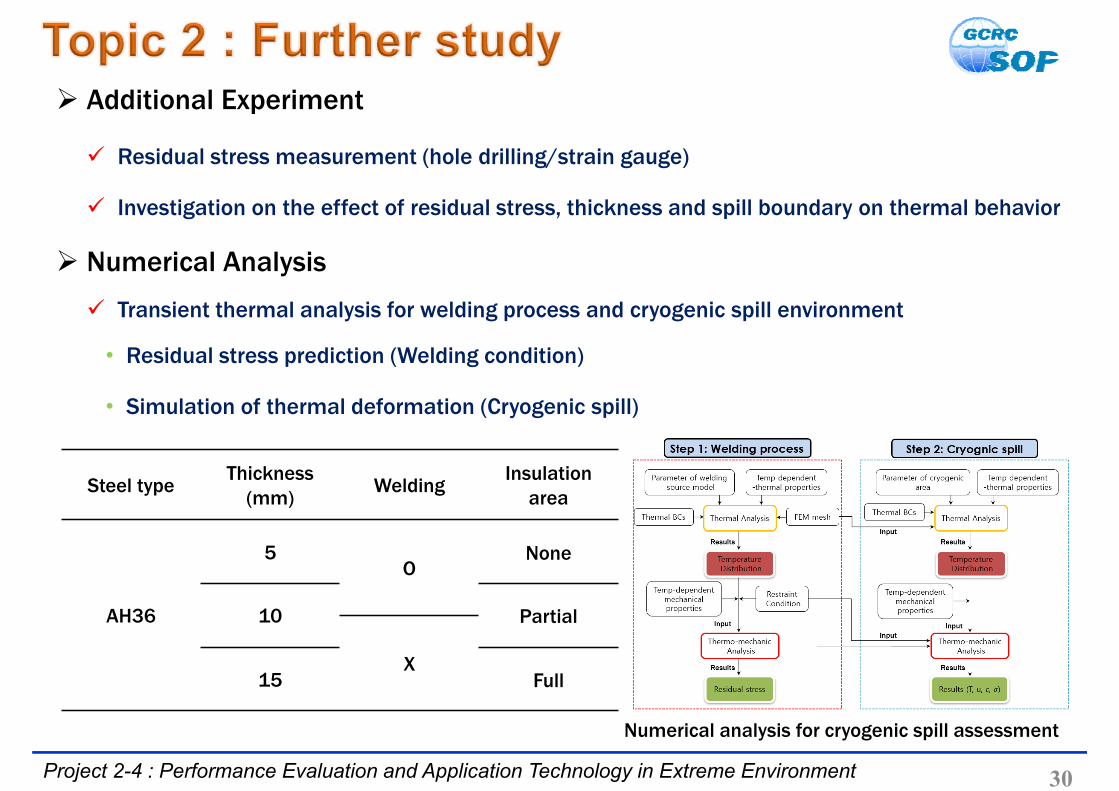
Residual stress measurement (hole drilling/strain gauge)
Investigation on the effect of residual stress, thickness and spill boundary on thermal behavior
Additional Experiment
Steel typeThickness
(mm)Welding
Insulation area
AH36
5O
None
10 Partial
X15 Full
Numerical analysis for cryogenic spill assessment
Transient thermal analysis for welding process and cryogenic spill environment
• Residual stress prediction (Welding condition)
• Simulation of thermal deformation (Cryogenic spill)
Numerical Analysis

31
Publications International Journal (SCI)
• 9 papers Domestic Journal (non-SCI)
• 6 papers Conference Presentation
• 50 papers (domestic) & 4 papers (international)
Education MS Graduate
• 3 people Ph. D. Graduate
• 1 people
Intellectual Properties Pending
• 3 domestic patent Registered
• 2 domestic patent
Enter Project No: Project Title in Slide Master

33Project 2-4 : Performance Evaluation and Application Technology in Extreme Environment
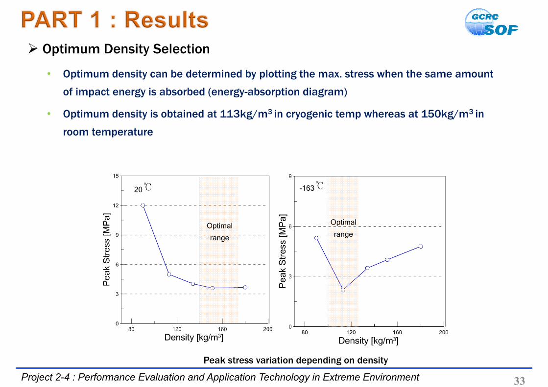
Optimum Density Selection
Peak stress variation depending on density
20℃ -163℃
Optimal
range
Optimal
range
• Optimum density can be determined by plotting the max. stress when the same amount
of impact energy is absorbed (energy-absorption diagram)
• Optimum density is obtained at 113kg/m3 in cryogenic temp whereas at 150kg/m3 in
room temperature
34Project 2-4 : Performance Evaluation and Application Technology in Extreme Environment
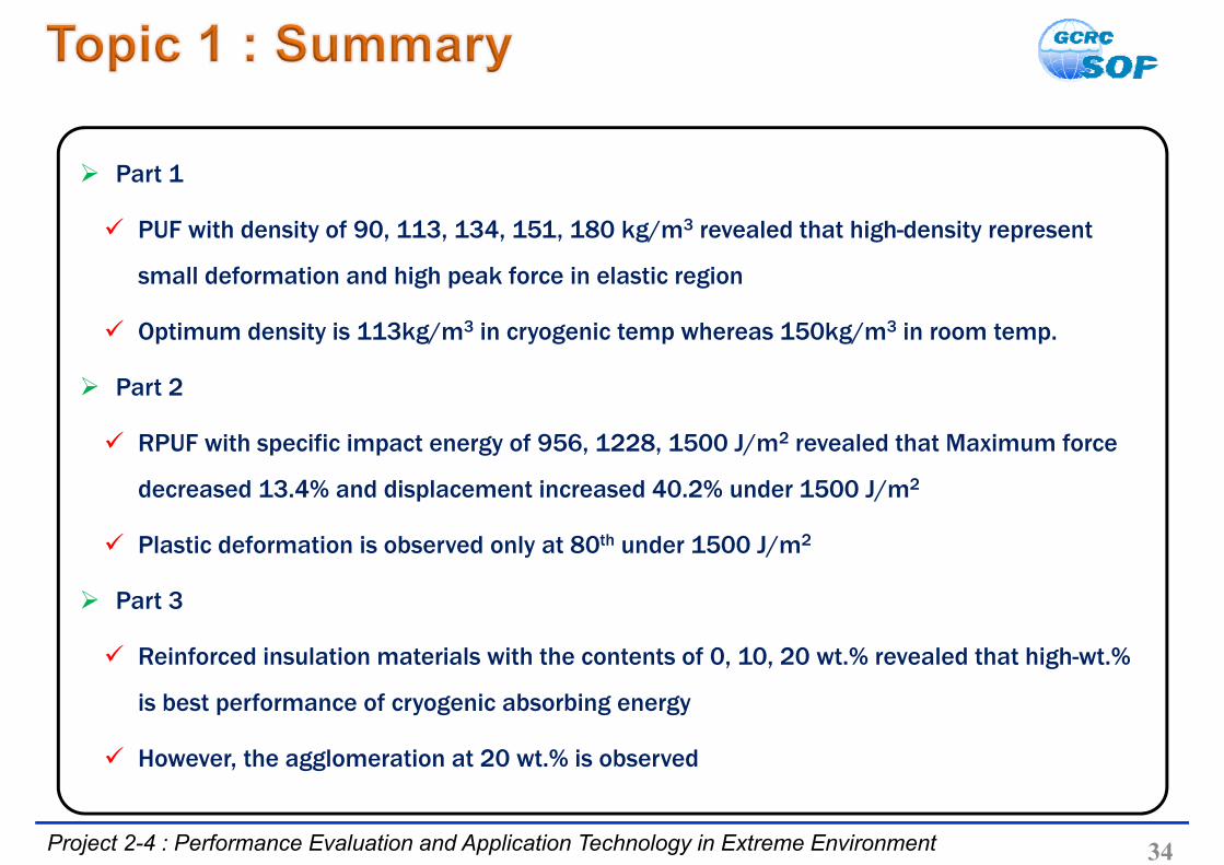
Part 1
PUF with density of 90, 113, 134, 151, 180 kg/m3 revealed that high-density represent
small deformation and high peak force in elastic region
Optimum density is 113kg/m3 in cryogenic temp whereas 150kg/m3 in room temp.
Part 2
RPUF with specific impact energy of 956, 1228, 1500 J/m2 revealed that Maximum force
decreased 13.4% and displacement increased 40.2% under 1500 J/m2
Plastic deformation is observed only at 80th under 1500 J/m2
Part 3
Reinforced insulation materials with the contents of 0, 10, 20 wt.% revealed that high-wt.%
is best performance of cryogenic absorbing energy
However, the agglomeration at 20 wt.% is observed
35Project 2-4 : Performance Evaluation and Application Technology in Extreme Environment
Preliminary Test
The notch was not sharp enough to show sufficient stress concentration → No crack
Structure with the welding defect are extremely vulnerable to crack propagation
under cryogenic spill
Experimental Investigation on Cryogenic Spill
Outside the boundary, the deformation were different in accordance with axial direction.
Regardless of liquid nitrogen contact, large strain was measured near the welding part.
Near welding part + outside boundary → a large amount of permanent deformation occurs.