gb condensing warm air heater eco operating, … · eco 1 code hg0140.00gb-m ed.a-1507 operating,...
TRANSCRIPT

1 code HG0140.00GB-M ed.A-1507ECO
Operating, Installation and Maintenance Manual CONDENSING WARM AIR HEATER ECOGB
This
man
ual c
anno
t be
copi
ed in
par
t or i
n fu
ll fo
r dis
clos
ure
to th
ird p
artie
s w
ithou
t the
prio
r writ
ten
cons
ent b
y C
omba
t HVA
C L
imite
d

2code HG0140.00GB-M ed.A-1507 ECO
WARM AIR HEATER ECO
Declaration of Conformity
COMBAT HVAC LIMITED
Unit A, Kings Hill Business ParkDarlaston Road, WednesburyWest Midlands, WS10 7SH UKTelephone: 0121 506 7700Fax: 0121 506 7701www.combat.co.uk
With this document we declare that the unit:
Model: Warm air heater ECO, ECOxxEA, ECOxxB, ECOxxBE
has been designed and manufactured in compliance with the prescriptions of the following EC Directives:
Machinery Directive 2006/42/CE
Gas Appliance Directive 2009/142/CE (ex 90/396/CE)
Electromagnetic Compatibility Directive 2004/108/CE or 2014/30/UE
Low Voltage Directive 2006/95/CE or 2014/35/UE
If the unit is to be installed into an equipment (combined), the manufacturer disclaims any responsibility if this equipment is not previously declared compliant with the requirements specified in IIB Enclosure of the above said Machinery Directive.
COMBAT HVAC LIMITED
CODE SERIAL NUMBER
3 code HG0140.00GB-M ed.A-1507ECO
WARM AIR HEATER ECO

4code HG0140.00GB-M ed.A-1507 ECO
WARM AIR HEATER ECO
5 code HG0140.00GB-M ed.A-1507ECO
WARM AIR HEATER ECO
INDEX
SECTION 1. GENERAL CAUTIONS ................................................................... 6
SECTION 2. SAFETY INSTRUCTIONS ............................................................. 62.1 Fuel ............................................................................................... 6 2.2 Gas Leaks ...................................................................................... 62.3 Power Supply ................................................................................. 72.4 Operation ...................................................................................... 7 2.5 Maintenance .................................................................................. 72.6 Transport and Handling ................................................................. 72.7 Packaging ...................................................................................... 7
SECTION 3. TECHNICAL FEATURES ............................................................... 83.1 Technical Data ............................................................................... 93.2 Dimensions .................................................................................... 10
SECTION 4. USER'S INSTRUCTIONS .............................................................. 124.1 Operating Cycle ............................................................................. 124.2 Accessories ................................................................................... 124.3 Interface Panel ............................................................................... 144.4 Reset ............................................................................................. 154.5 Set-up ........................................................................................... 16
SECTION 5. INSTALLATION INSTRUCTIONS................................................... 175.1 General Installation Instructions .................................................... 175.2 Installation ...................................................................................... 175.3 Condensation Drainage ................................................................. 195.4 Connections to the Flue ................................................................. 205.5 Electrical Connections ................................................................... 265.6 Modulation PCB Parameters ......................................................... 285.7 Analysis of lockouts - Faults ......................................................... 31
SECTION 6. GAS CONNECTION ....................................................................... 33
SECTION 7. SERVICING INSTRUCTIONS ......................................................... 347.1 Country Table - Gas Category ...................................................... 347.2 Gas Settings Table ......................................................................... 357.3 ConfiguringwithLCDDisplay ........................................................ 387.4 Startingupforthefirsttime ............................................................ 397.5 Analysis of combustion .................................................................. 397.6 Conversion to LPG ........................................................................ 407.7 Conversion to gas G25 - G25.1 ..................................................... 417.8 Conversion to gas G2.350 ............................................................. 417.9 Replacing the gas valve ................................................................. 427.10 Replacing STB and NTC ............................................................... 427.11 Replacing the modulation PCB ...................................................... 42
SECTION 8. MAINTENANCE .............................................................................. 43
SECTION 9. WIRING DIAGRAMS ...................................................................... 44
SECTION 10. LIST OF SPARE PARTS................................................................. 4510.1 Parts for the electrical panel .......................................................... 4510.2 Parts for the burner unit ................................................................. 46

6code HG0140.00GB-M ed.A-1507 ECO
WARM AIR HEATER ECO
1. GENERAL CAUTIONSThis manual is an integral part of the product and must always accompany it. Should the equipment be sold or passed on to someone else, always make sure that this manual is supplied with the equip-ment for future reference by the new owner and/or installer. The manufacturer shall not be held civilly or criminally respon-sible for injuries to people or animals or damages to things caused by incorrect installation, calibration and maintenance or by failure to follow the instructions contained in this manual orbyoperationscarriedoutbyunqualifiedstaff.This product must be used only for the applications for which it was designed or approved. Any other use must be regarded as hazardous.During the installation, operation and maintenance of the equip-ment described in this manual, the user must always strictly follow the instructions given in all the chapters of this operating and maintenance manual. ----------------------------------------------------------------------------------The warm air heater must be installed in compliance with current regulations, according to the manufacturer's instruc-tions and by suitably qualified staff. who has the technical knowledge in the heating sector. ----------------------------------------------------------------------------------Conversion between different types of gas and maintenance operations must be carried out before being switched on, and only by suitably qualified staff. Technical Service Centres certified by current and older standards. F o r m o r e i n f o r m a t i o n , v i s i t o u r W e b s i t e www.combat.co.uk or contact the manufacturer directly. The warranty conditions for this equipment can be found in the Combat HVAC Limited Terms and Conditions Of Sale
Reference standards (only applies to Italy):
• Ministerial Decree No. 74 of 12/04/96;• Ministerial Decree No. 37 of 22/01/2008;• UNI-CIG 7129-1, -2, -3, -4 standard, which regulates the
installationofnaturalgasfiredequipment;• UNI-CIG 7131 standard, which regulates the installation
ofLPGfiredequipment;• Law No. 10/91 and Presidential Decree No. 412/93 on
reducing energy consumption;• Legislative Decree 192/05 of 19/08/2005;• Legislative Decree 311 of 29/12/2006;• UNI CIG 11528:2014 standard "Design, installation and
commissioning gas systems with heat output higher than35 kW".
These standards may be subject to changes and/or additions.
2. SAFETY INSTRUCTIONSThis chapter describes the safety instructions to be followed by the installer.
2.1. FuelBefore starting up the heater, make sure that:• the gas mains supply data is compatible with the data
stated on the dataplate• thecombustionairintakeducts(whenfitted)andtheflue
exhaustpipesarethosespecifiedbythemanufacturer;• the combustion air is supplied in such a way as to avoid
even partial obstructions of the intake grille (caused byleavesetc.);
• the fuel intake internal and external seal is checked duringthe testing stage, as required by applicable standards;
• the heater is supplied with the same type of fuel it hasbeen designed for;
• the system is correctly sized for such flow rate and isfittedwithall safetyandmonitoringdevices requiredbyapplicable standards;
• the inside of the gas pipes and air distribution ducts forducted heaters has been thoroughly cleaned;
• thefuelflowrateissuitableforthepowerrequiredbytheheater;
• the fuelsupplypressure isbetween therangespecifiedon the dataplate.
2.2. Gas LeaksIf you smell gas:• do not operate electrical switches, telephones or any other
object or device that could produce sparks;• immediatelyopendoorsandwindowstocreateanairflow
to vent the gas out of the room;• close the gas valves;• Contact your gas provider
7 code HG0140.00GB-M ed.A-1507ECO
WARM AIR HEATER ECO
If the equipment is not used for long periods, shut the gas sup-ply off through the gas shut off valve and disconnect it from the power supply.If the heater is to be put out of service, in addition to the above operations, potential sources of hazard on the unit must be removed.It is strictly forbidden to obstruct the Venturi pipe inlet, located on the burner-fan unit, with your hands or with any other objects. Anyobstructioncouldcauseabackfirefromthepremixedburner.
2.6. Transport and HandlingThe heater is delivered fastened to a pallet and covered with a suitably secured cardboard box.Unload the heater from the truck and move it to the site of installation by using means of transport suitable for the shape of the load and for the weight.If the unit is stored at the customer’s premises, make sure a suitable place is selected, sheltered from rain and from excessive humidity, for the shortest possible time.Any lifting and transport operations must be carried out by skilled staff, adequately trained and knowledgeable on the working procedures and safety regulations.Once the equipment is moved to the correct position, the un-packing operation can be started.
2.7. PackagingThe unpacking operation must be carried out by using suitable tools or safety devices where required. Recovered packaging materials must be separated and disposed of according to ap-plicable regulations in the country of use. While unpacking the unit, check that the unit and all its parts have not been damaged during transport and match the order. If damage has occurred or parts are found to be missing, immediately contact the sup-plier. The manufacturer is not liable for any damages occurred during transport, handling or unloading.
2.3. Power supplyThe equipment must be correctly connected to an effective earthing system, made in compliance with current regulations (CEI64-8,onlyappliestoItaly).
Cautions• Check the effectiveness of the earthing system and, if
required,calloutaqualifiedengineer.• Check that the mains power supply is the same as the
power input stated on the equipment dataplate and in this manual.
• Do not swap the neutral with the live wire.• Theelectricalsystemand,morespecifically,thecablesec-
tion, must be suitable for the equipment maximum power input , shown on the dataplate and in this manual.
Do not pull electric cables and keep them away from heat sources.---------------------------------------------------------------------------------NOTE: It is compulsory to install, upstream of the power cable, a fused multi-pole switch with contact opening wider than 3mm.The switch must be visible, accessible and less than 3m away from the control board.All electrical operations (installation and maintenance) must be carried out by suitably qualified staff.---------------------------------------------------------------------------------
2.4. OperationDo not allow children or inexperienced people to use any electri-cally powered equipment.The following instructions must be followed:• do not touch the equipment with wet or damp parts of your
body and/or with bare feet;• do not leave the equipment exposed to the elements (rain,
sunetc....)unlessitisadequatelyprotected;• do not use the gas pipes to earth electrical equipment;• do not touch the hot parts of the heater, such as the flue
gas exhaust duct;• donotwettheheaterwithwaterorotherfluids;• do not place any object over the equipment;• do not touch the moving parts of the heater:
2.5. Maintenance---------------------------------------------------------------------------------Maintenance operations and combustion inspections must be carried out in compliance with current standards.---------------------------------------------------------------------------------Before carrying out any cleaning and maintenance operations, isolate the heater from the mains power supply via the switch located on the electrical system and/or on the shut-off devices.If the heater is faulty and/or incorrectly operating, switch it off and do not attempt to repair it yourself, but contact the local Technical Service Centre. All repairs must be carried out by using genuine spare parts. Failure to comply with the above instructions could compromise the safety of the equipment and invalidate the warranty.

8code HG0140.00GB-M ed.A-1507 ECO
WARM AIR HEATER ECO
DO NOT COVER IT WITH YOUR HAND OR OTHER OBJECTS!
WARNING: Before switching on the heater, open the lou-vres by at least 45°
HG0140.00_IM_001
3. TECHNICAL FEATURESThe ECO series modulating warm air heaters have been de-signed for industrial and commercial environments.The heater PCB continually modulates the heat output between the minimum and maximum power, according to heating re-quirements.The premixing and modulating technology allows the heater to achieveefficiencyabove108%oftheL.C.V.The heater can operate independently; it can be started up by simply connecting it to the power mains and to the gas mains.The heaters' heat output ranges from 5 to 97kW.
The units can be controlled:• from an external time/temperature control;• externally with the modbus (through SmartControl, Smart.
netorSmart.web);• proportionally, with a 0-10 Vdc external control.
The heat exchanger complies with the manufacturing require-ments for condensing warm air heaters, and with standards EN1020 and EN1196.
The combustion chamber and the surfaces of components where condensation occurs (such as the pipe bundle and exhaust hood),aremadeofAISI441,inordertoprovidehighresistanceto condensation and temperature. The following table illustrates the types of stainless steels used:USA-AIS EN-No. COMPOSITIONAISI 441 1.4509 X2 CrTiNb 18
The innovative design and the large heat exchanging surface of the combustion chamber and of the tubes ensure optimum efficiencyanddurability.The burner is made entirely of stainless steel with special me-chanical solutions to ensure optimal reliability and performance levels, as well as high thermal and mechanical resistance.
The control located on the front panel allows the service centre to check and view the working phases and identify any faults that may have occurred.
Inherent SafetyThe performance increase at minimum power is achieved by using a sophisticated air/gas mixing technique and by adjusting at the same time the combustion air and the fuel gas.This technology increases the heater safety as the gas valve suppliesthefuelaccordingtotheairflow.Unlikewithatmos-pheric burners, the CO2 proportion remains constant throughout theheateroperatingrange,allowingittoincreaseitsefficiencywhen the heat output reduces.If there is no combustion air, the valve will not supply gas; if thecombustionairflowreduces, thevalvewillautomaticallyreducethegasflowyetwillkeepitscombustionparametersat optimal levels.
Low emissionsThe premixed burner, in combination with the air/gas valve, ensures "clean" efficient combustion with low emissions ofpollutants.

9 code HG0140.00GB-M ed.A-1507ECO
WARM AIR HEATER ECO
Model: ECO20A ECO34A ECO45A ECO65A ECO80A ECO105A
Type of equipment B23P - B53P - C13 - C43 - C53 - C63
ECcertification PIN. 0476CQ0451
NOx Class Val 5
Heater Performance
min max min max min max min max min max min max
Burnerheatoutput(Hi) kW 4.75 19.00 7.60 34.85 8.50 42.00 12.40 65.00 16.40 82.00 21.00 100.00
Useful heat output kW 4.97 18.18 8.13 33.56 8.97 40.45 13.40 62.93 17.77 80.03 22.77 97.15
EfficiencyHi(NetC.V.) % 104.63 95.68 106.97 96.30 105.50 96.30 108.06 96.82 108.35 97.60 108.40 97.15
EfficiencyHs(GrossC.V.) % 94.26 86.20 96.37 86.76 95.07 86.76 97.36 87.22 97.62 87.93 97.68 87.52
Fluelosseswithburneron(Hi) % 0.4 4.3 0.6 3.7 0.5 3.7 0.2 3.2 0.3 2.4 0.2 2.8
Fluelosseswithburneroff(Hi) % <0.1 <0.1 <0.1 <0.1 <0.1 <0.1
Losses in enclosure (1) 0% 0% 0% 0% 0% 0%
Max. condensation (2) l/h 0.4 0.9 1.1 2.1 3.3 2.7
Flue gas emissions
Carbonmonoxide-CO-(0%ofO2)(3) ppm < 5 < 5 < 5 < 5 < 5 < 5
Nitrogenoxides-NOx-(0%ofO2)(4) 38 mg/kWh -
22 ppm42 mg/kWh -
24 ppm33 mg/kWh -
19 ppm39 mg/kWh -
22 ppm32 mg/kWh -
18 ppm41 mg/kWh -
23 ppm
Availablepressureatflue Pa 80 90 100 120 120 120
FLUE GAS temperature, CO2contentandmaximumfluegasflowrate:seegastablesonpage37andonthefol-lowing pages
Electrical Data
Power supply V 230 Vac - 50 Hz single-phase
Power input W 147 180 270 310 280 310 425 510 500 613 650 750
Power input in stand-by W <5
Ingress Protection Rating IP IP 20
Operating Temperatures °C from -15°C a +40°C - for lower temperature, a burner housing heating kit is required
Storage Temperatures °C from -25°C to +60°C
Connections
Ø gas connection (5) GAS UNI/ISO 228/1- G 3/4"
UNI/ISO 228/1- G 3/4"
UNI/ISO 228/1- G 3/4"
UNI/ISO 228/1- G 3/4"
UNI/ISO 228/1-
G 3/4" (6)UNI/ISO 228/1-
G 3/4" (6)
Ø Combustion air intake/exhaust pipes mm 80/80 80/80 80/80 80/80 100/100 (7) 100/100 (7)
Air flow rate
Airflowrate m3/h 2700 4300 4500 7800 9000 11100
Air temperature increase °C 5.28 19.30 5.42 22.37 5.73 25.74 4.92 23.13 5.66 25.49 5.89 25.09
Number and diameter of fans 1 x Ø350 1 x Ø 450 1 x Ø450 2 x Ø400 2 x Ø450 3 x Ø400
Fans speed rpm 1370 1370 1370 1370 1370 1370
Soundpowerlevel(Lw)(8) dB(A)
Weight
Net weight kg 70 77 98 125 143
Weight when packaged kg 85
NOTES:(1)Thelossesfromtheenclosuremustberegardedaszeroastheheaterisinstalledinaheatedenvironment.(2) Max..condensationproducedacquiredfromtestingat30%Qn.(3) Valuereferencedtocat.H(G20)(4) WeightedvaluetoEN1020ref.toclassH(G20),referredtoHi(L.C.V.).(5)Thegaslinemustbemeasuredbytakingintoaccountthelengthofthepipesandnottheheaterdiameter.
For countries requiring an ISO connection different from the one shown above, an adaptor will be supplied.(6) FortheECO80AandECO105Amodels,theminimumgassupplyductdiametermustbeUNI/ISO 228/1- G 1".(7) Ø100/100obtainedbyusingadaptorssuppliedasstandard.(8) Measuredatadistanceof5mfromthemachine.
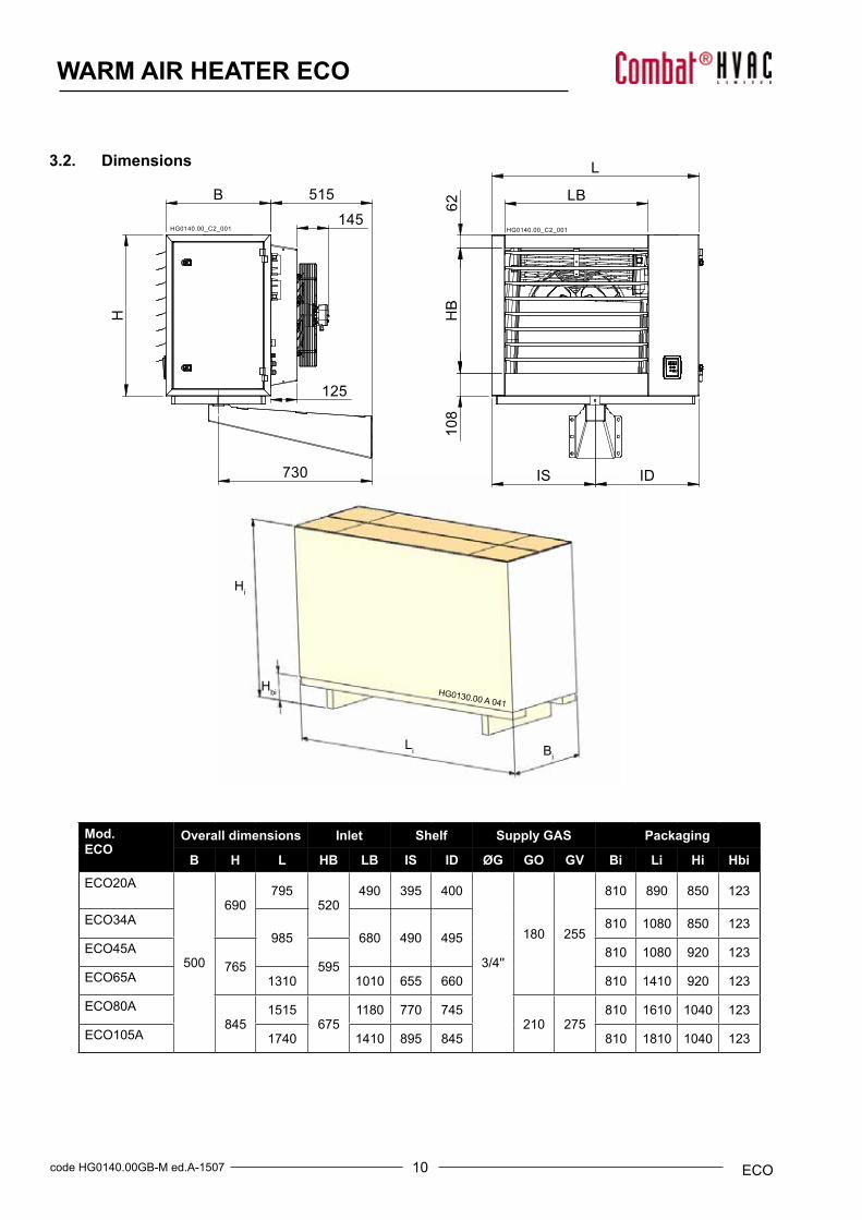
3.1. Technical Data
10code HG0140.00GB-M ed.A-1507 ECO
WARM AIR HEATER ECO
Mod. ECO
Overall dimensions Inlet Shelf Supply GAS Packaging
B H L HB LB IS ID ØG GO GV Bi Li Hi Hbi
ECO20A
500
690795
520490 395 400
3/4''
180 255
810 890 850 123
ECO34A985 680 490 495
810 1080 850 123
ECO45A765 595
810 1080 920 123
ECO65A 1310 1010 655 660 810 1410 920 123
ECO80A845
1515675
1180 770 745210 275
810 1610 1040 123
ECO105A 1740 1410 895 845 810 1810 1040 123
BiLi
Hbi
Hi
145
HG0140.00_C2_001
HG0140.00_C2_001
HG0140.00_C2_001
HG0140.00_C2_001
IS ID
HB
L
108
LB
62
H
730
515 B
125
TO
A
S
F
AO
A
GV
GO
TV
AV
SF
G HG0130.00 A 041
3.2. Dimensions
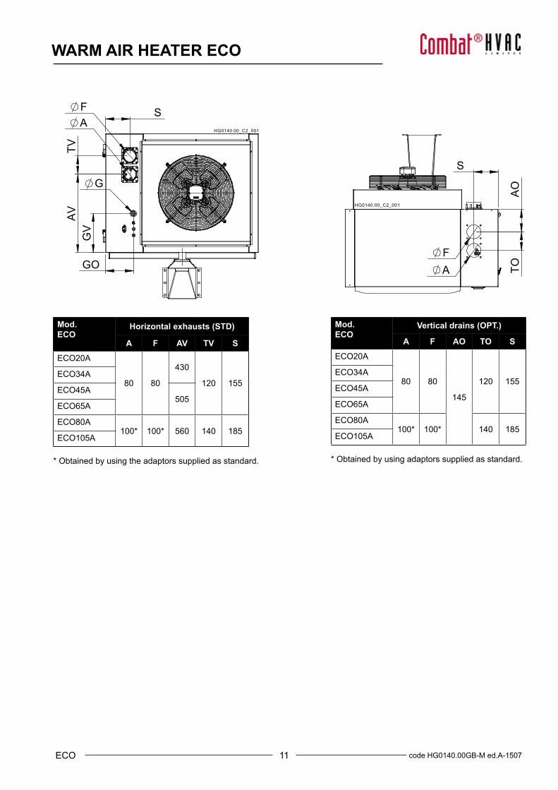
11 code HG0140.00GB-M ed.A-1507ECO
WARM AIR HEATER ECO
Mod. ECO
Horizontal exhausts (STD)
A F AV TV S
ECO20A
80 80
430
120 155ECO34A
ECO45A505
ECO65A
ECO80A100* 100* 560 140 185
ECO105A
* Obtained by using the adaptors supplied as standard.
Mod. ECO
Vertical drains (OPT.)
A F AO TO S
ECO20A
80 80
145
120 155ECO34A
ECO45A
ECO65A
ECO80A100* 100* 140 185
ECO105A
* Obtained by using adaptors supplied as standard.
145
HG0140.00_C2_001
HG0140.00_C2_001
HG0140.00_C2_001
HG0140.00_C2_001
IS ID
HB
L
108
LB
62
H
730
515 B
125
TO
A
S
F
AO
A
GV
GO
TV
A
V
S F
G
12code HG0140.00GB-M ed.A-1507 ECO
WARM AIR HEATER ECO
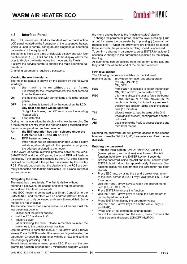
Cable colour:1. Brown2. Black3. Blue4. Grey
CN08
ID4IDC2ID3ID2
HG0140.00_IIM_037
4. USER'S INSTRUCTIONS
4.1. Operating CycleThe wall mounted ECO heaters operation is fully automatic; they are equipped with electronic equipment with self check facility that manages all the burner control and monitoring operations and with a microprocessor based electronic PCB that controls the heat output regulation.
The heat demand depends on the PCN parameter d0 of the heater electronic PCB:• d0=2: input ID2-IDC2 closed and NTC1<TH1;• d0=5: input ID2-IDC2 closed and input 0-10Vdc>Von;• d0=7: input ID2-IDC2 closed and control from Modbus ON.
The ignition request occurs when the following conditions are met:• when the heater is powered on and is not in a lockout
condition;• when the contact is closed on terminals ID2/IDC2 of the
heater PCB.When these conditions are met, the burner fan will be immedi-atelystarted;whenthepre purging-timehasexpired,theflamewillbelitwithanignitionpowerofapproximately50%ofthemaximumpower.Oncetheflamestabilisingtimehasexpired,the burner will start to modulate its heat output according to the supply air temperature.If there isnoflameduringtheignitionstage,theequipmentmakes4ignitionattempts;if,atthefifthattempt,ignitionisstillunsuccessful, the heater will be locked out.The heater will be switched on when the ID2/IDC2 contact opens on the terminal box; disconnecting the power supply is prohibited, except for emergencies because, if the heater is switched off, the flue gas extractor fan will continue to work for approximately 90 seconds to clean up the combustion chamber (combustion chamberpost-cleaningphase).Failure to perform the post-cooling operations on the exchanger will:• reduce the life of the exchanger and invalidate the warranty;• cause the safety thermostat to operate and require a
manual reset.If, during the cooling cycle, there is a new demand for heat, the modulation PCB will wait for the cooling fans to shut down and then reset the counters to start a new cycle. Parameter d6 of the modulation PCB, which can be programmed from 0 to 256 seconds, controls the minimum interval between the time the equipment is switched off and restarted.----------------------------------------------------------------------------------IMPORTANT: P owering off the machine before completing the cooling cycle and with machine set to ON is strictly prohibited. Failure to follow these instructions shall in-validate the warranty and cause early deterioration of the heat exchanger.-----------------------------------------------------------------------------------
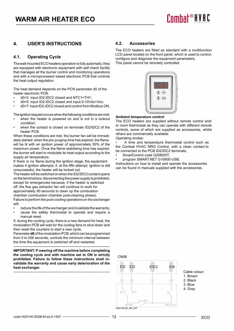
4.2. AccessoriesTheECOheatersarefittedasstandardwithamultifunctionLCD panel located on the front panel, which is used to control, configureanddiagnosetheequipmentparameters.This panel cannot be remotely controlled.
Ambient temperature controlThe ECO heaters are supplied without remote control and/or room thermostat as they can operate with different remote controls, some of which are supplied as accessories, whilst others are commercially available.Operating modes:• A time and temperature thermostat control such asthe Combat HVAC NRG Control, with a clean contact tobe connected to the PCB ID2/IDC2 terminals;• SmartControl code G20800IT;• program SMART.NET G16900-USB.Instructions on how to install and operate the accessoriescan be found in manuals supplied with the accessories.
13 code HG0140.00GB-M ed.A-1507ECO
WARM AIR HEATER ECO
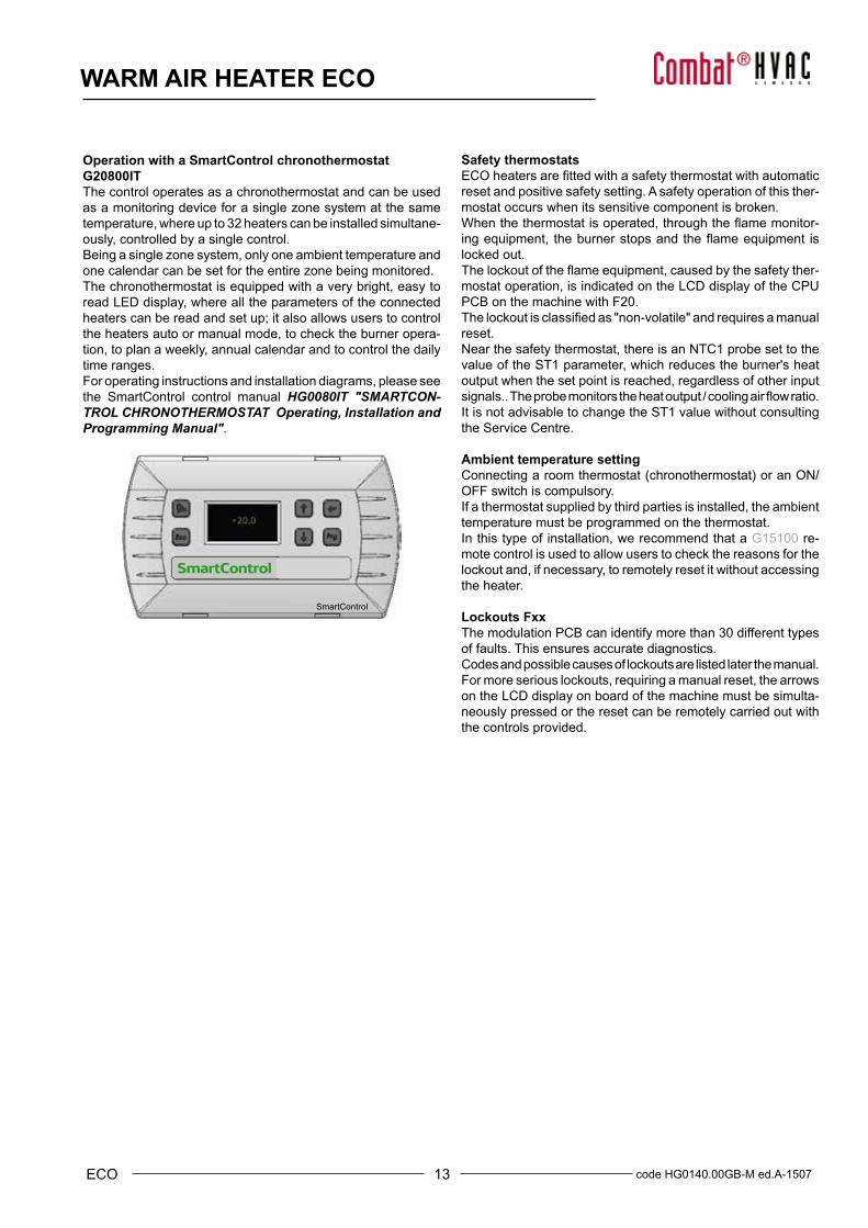
Operation with a SmartControl chronothermostatG20800ITThe control operates as a chronothermostat and can be used as a monitoring device for a single zone system at the same temperature, where up to 32 heaters can be installed simultane-ously, controlled by a single control.Being a single zone system, only one ambient temperature and one calendar can be set for the entire zone being monitored. The chronothermostat is equipped with a very bright, easy to read LED display, where all the parameters of the connected heaters can be read and set up; it also allows users to control the heaters auto or manual mode, to check the burner opera-tion, to plan a weekly, annual calendar and to control the daily time ranges. For operating instructions and installation diagrams, please see the SmartControl control manual HG0080IT "SMARTCON-TROL CHRONOTHERMOSTAT Operating, Installation and Programming Manual".
Safety thermostatsECOheatersarefittedwithasafetythermostatwithautomaticreset and positive safety setting. A safety operation of this ther-mostat occurs when its sensitive component is broken. Whenthethermostatisoperated,throughtheflamemonitor-ingequipment, theburnerstopsandtheflameequipment islocked out.Thelockoutoftheflameequipment,causedbythesafetyther-mostat operation, is indicated on the LCD display of the CPU PCB on the machine with F20.Thelockoutisclassifiedas"non-volatile"andrequiresamanualreset.Near the safety thermostat, there is an NTC1 probe set to the value of the ST1 parameter, which reduces the burner's heat output when the set point is reached, regardless of other input signals..Theprobemonitorstheheatoutput/coolingairflowratio.It is not advisable to change the ST1 value without consulting the Service Centre.
Ambient temperature settingConnectingaroomthermostat(chronothermostat)oranON/OFF switch is compulsory.If a thermostat supplied by third parties is installed, the ambient temperature must be programmed on the thermostat. In this type of installation, we recommend that a G15100 re-mote control is used to allow users to check the reasons for the lockout and, if necessary, to remotely reset it without accessing the heater.
Lockouts Fxx The modulation PCB can identify more than 30 different types of faults. This ensures accurate diagnostics.Codes and possible causes of lockouts are listed later the manual.For more serious lockouts, requiring a manual reset, the arrows on the LCD display on board of the machine must be simulta-neously pressed or the reset can be remotely carried out with the controls provided.
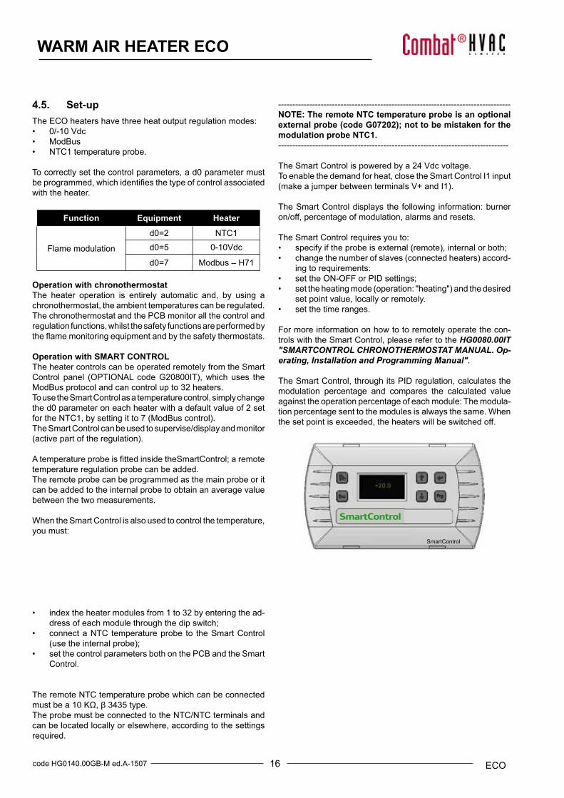
SmartControl
14code HG0140.00GB-M ed.A-1507 ECO
WARM AIR HEATER ECO
4.3. Interface PanelTheECOheatersarefittedasstandardwithamultifunctionLCD panel located on the front panel of the suspended heater, whichisusedtocontrol,configureanddiagnosealloperatingparameters of the equipment.Thepanelisfittedwithared3digitLCDdisplayandwithfourfunctionkeys:↑,↓,ESCandENTER;thedisplayallowstheuser to display the heater operating mode and its Faults.It allows the service centre to change the main operating pa-rameters.Changing parameters requires a password.
Viewing the machine statusThe machine status is shown on the display by the following wordings:rdy the machine is on without burner f lame,
it is waiting for the ON control and/or the heat demand from the thermostat;
On themachineisonwithburnerflameorisintheignition phase;
OFF the machine is turned off by the control on the LCD.Any heat demands will be ignored. To light the burner, the LCD must show the wording "heater ON";
Fxx Fault detected.During normal operation, the display will show the wording On if the burner is on; rdy when the heater is being switched off or the room temperature has been reached.Air the EST operation has been selected under the
FUN menu; set FUN to ON or OFF;Axx ECO heater address;
If the heater has an address other than Ø, the display will show, alternating it with the operation in progress, the address assigned to the heater.
In the event of communication problems between the CPU-SMART PCB and the LCD panel, the word CPUwillflashonthedisplayiftheproblemiscausedbytheCPU;threeflashingdots will be displayed if the problem is caused by the display PCB. If needs be, check that the display and the PCB are cor-rectly connected and that the small cable RJ11 is securely held in the connector.
Navigating the menuThemenuhasthreelevels.Thefirstisvisiblewithoutenteringa password, the second and third require entering second and third level passwords.If the ECO heater is connected to a Smart Control or to the SMART.NET, and therefore with an address different from Ø, parameterscanonlybeviewedandcannotbemodified.Somemenus are not available.The Service Centre that is required to use all menus must fol-low these instructions:• disconnect the power supply;• set the PCB address to Ø;• restore power;• after finishing the work, please remember to reset the
switches to the previously set position.Usethearrowstoscrollthemenus:↑(uparrow)and↓(downarrow).PressENTERtoselectthemenu,andagaintoselecttheparameter.Changetheparameterwiththearrowsandconfirmthe change by pressing ENTER.To exit the parameter or menu, press ESC. If you exit the pro-gramming function, after about 10 minutes the program will exit
the menu and go back to the "machine status" display.Tochangetheparameter,pressthearrowkeys:pressing↑(uparrow)increasestheparameterby1,pressing↓(downarrow)reduces it by 1. When the arrow keys are pressed for at least three seconds, the parameter scrolling speed is increased. Toconfirmachangeinparameters,pressENTERforatleast3seconds. A change in the parameter is indicate by the display flashing.All submenus can be scrolled from the bottom to the top, and they start over when the end of the menu is reached.
First level menusThefollowingmenusareavailableonthefirstlevel:machine status provides information about its operation
(ex.rdy,ON,etc.);ON,OFF);
FUN from FUN it is possible to select the function ON,OFForEST(donotselectEST);
REG this menu allows the user to force the burner to the minimum or the maximum for combustion tests; it automatically returns to the previous position at the end of the preset time(10minutes);
TIN allows the user to read the value of the 0/10 Vdcsignal(ifpresent)comingintotheheater;
Pra not used;ABI used to enter the PWD to access second and
third level menus.
Entering the password 001 will provide access to the second level and make the Set Point, I/O, Parameters and Fault menus available.
Entering the password• Fromtheinitialscreen(ON/OFF/rdy/FXX)usethe↑
(arrow up)and↓(arrowdown)keystoreachtheABIfunction;hold down the ENTER key for 3 seconds;
• SetthepasswordinsidetheABIandmenuconfirmitwithENTER; hold it down for approximately 3 seconds (theflashingdisplaywillconfirmthattheparameterhasbeenstored);
• PressESCand,byusingthe↑and↓arrowkeys,returntotheinitialscreen(ON/OFF/rdy/FXX);pressENTERfor3 seconds;
• Usethe↑and↓arrowkeystoreachthedesiredmenuitem (Flt,I/O,SET,PAR);
• Press ENTER to access the function;• Usethe↑and↓arrowkeystoselecttheparametersto
be displayed and edited;• Press ENTER to display the parameter value;• Usethe↑and↓arrowkeystoeditthevalue(onlySET
andPAR);• PressENTERtoconfirmthechangemade;• To exit the parameter and the menu, press ESC until the
initialscreenisdisplayed(ON/OFF/rdy/FXX).
15 code HG0140.00GB-M ed.A-1507ECO
WARM AIR HEATER ECO
Second and third level menusThe second and third level menus are reserved to the Service Centre and can be accessed only by entering a password, which can be requested for the manufacturer's Service Centre. For more detail, see Paragraph 7.3 "Programming with a LCD panel".
Fault listIn the event of a lockout, the heater PCB will display a code, which indicates what problem has occurred.To reset the heater, simultaneously simply press the LCD panel arrow keys for at least 3 seconds or operate one of the remote controls provided. TheFaultsareclassifiedaccordingtothetypeoferror;themostcommon and easier to sort out by user are:F1x these faults are caused by the burner failed ignition; they all require a manual reset.F20 heater safety thermostat lockout; this fault must be manually reset.F21 jumper missing between terminals ID1 and IDC1 or firebreakerconnectedtoterminalsID2andIDC2tripped.F3x F4x
lockouts caused by faults of the flue gas extractor. lockouts caused by an error or by a missing temperature
probe; they must be sorted out by the Service Centre.F51 the temperature of the air supplied has exceeded the upper limit set in parameter TH1; as the temperature drops, the lockout will sort itself out; manual reset is not required.F60 on the LCD panel only, the heater is connected to a SmartControl or to SMART.NET but does not communicate. When communication is restored, the lockout condition will disappear; manual reset is not required.
The list and meanings of all faults are shown in the FAULT table in Paragraph 5.7 "Analysis of Lockouts - Faults".
4.4. ResetThe modulation PCB allows the operator to identify more than thirty different causes of lockouts. This makes it possible to manage each event very accurately.To reset the lockouts, press both arrows simultaneously for a few seconds. Lockouts may be remotely controlled by using:• the digital input ID4-IDC4 - button N.O.;• the Smart Control - optional;• the ModBus protocol.Ifignitionfails,theflamemonitoringsystemreattemptsignitionfour times. After four failed attempts, it will lock out and willdisplay the code F10.The lockout codes and their cause is shown in the FAULT table in Paragraph 5.7 "Analysis of Lockouts - Faults".Iftheflamemonitoringequipmenthaslockedout(codesfromF10toF20),itcanberesetitbyusingthebuttonontheequip-ment itself. This lockout is shown by a LED that lights up onthe equipment.----------------------------------------------------------------------------------WARNING : The flame monitoring equipment memorisesthe number of manual resets that are performed during itslifetime. In case of five resets performed in a period of 15minutes, without a flame being ignited and detected, theequipment will go into a "timed" lockout (F13). In this case, it is required to wait another 15 minutes before resettingit again.Press the reset button on the equipment to immediatelyreset this lockout condition.----------------------------------------------------------------------------------NOTE: SHOULD THE SAFETY THERMOSTAT (STB) OPENBEFORE STARTING THE START-UP CYCLE (THIS COULD BE CAUSED, FOR EXAMPLE, BY LOW TEMPERATURES), THE PILOT LIGHT EQUIPMENT WILL BE KEPT IN "STAND-BY"AND FAULT F15 WILL BE SHOWN AFTER 300 SECONDS.---------------------------------------------------------------------------------
16code HG0140.00GB-M ed.A-1507 ECO
WARM AIR HEATER ECO
4.5. Set-upThe ECO heaters have three heat output regulation modes:• 0/-10 Vdc• ModBus• NTC1 temperature probe.
To correctly set the control parameters, a d0 parameter must beprogrammed,whichidentifiesthetypeofcontrolassociatedwith the heater.
Function Equipment Heater
Flame modulation
d0=2 NTC1d0=5 0-10Vdc
d0=7 Modbus – H71
Operation with chronothermostatThe heater operation is entirely automatic and, by using a chronothermostat, the ambient temperatures can be regulated. The chronothermostat and the PCB monitor all the control and regulation functions, whilst the safety functions are performed by theflamemonitoringequipmentandbythesafetythermostats.
Operation with SMART CONTROLThe heater controls can be operated remotely from the Smart Control panel (OPTIONALcodeG20800IT),which uses theModBus protocol and can control up to 32 heaters.To use the Smart Control as a temperature control, simply change the d0 parameter on each heater with a default value of 2 set fortheNTC1,bysettingitto7(ModBuscontrol).The Smart Control can be used to supervise/display and monitor (activepartoftheregulation).
AtemperatureprobeisfittedinsidetheSmartControl;aremotetemperature regulation probe can be added.The remote probe can be programmed as the main probe or it can be added to the internal probe to obtain an average value between the two measurements.
When the Smart Control is also used to control the temperature, you must:
• index the heater modules from 1 to 32 by entering the ad-dress of each module through the dip switch;
• connect a NTC temperature probe to the Smart Control(usetheinternalprobe);
• set the control parameters both on the PCB and the SmartControl.
The remote NTC temperature probe which can be connected mustbea10KΩ,β3435type.The probe must be connected to the NTC/NTC terminals and can be located locally or elsewhere, according to the settings required.
----------------------------------------------------------------------------------NOTE: The remote NTC temperature probe is an optional external probe (code G07202); not to be mistaken for the modulation probe NTC1.---------------------------------------------------------------------------------
The Smart Control is powered by a 24 Vdc voltage.To enable the demand for heat, close the Smart Control I1 input (makeajumperbetweenterminalsV+andI1).
The Smart Control displays the following information: burner on/off, percentage of modulation, alarms and resets.
The Smart Control requires you to:• specifyiftheprobeisexternal(remote),internalorboth;• changethenumberofslaves(connectedheaters)accord-
ing to requirements:• set the ON-OFF or PID settings;• settheheatingmode(operation:"heating")andthedesired
set point value, locally or remotely.• set the time ranges.
For more information on how to to remotely operate the con-trols with the Smart Control, please refer to the HG0080.00IT "SMARTCONTROL CHRONOTHERMOSTAT MANUAL. Op-erating, Installation and Programming Manual".
The Smart Control, through its PID regulation, calculates the modulation percentage and compares the calculated value against the operation percentage of each module: The modula-tion percentage sent to the modules is always the same. When the set point is exceeded, the heaters will be switched off.
SmartControl
17 code HG0140.00GB-M ed.A-1507ECO
WARM AIR HEATER ECO
5. INSTALLATION INSTRUCTIONSInstructions for installing and setting the heater are intended forsuitablyqualifiedpersonnelonly.
5.1. General Installation Instructions Where allowed, the heater can be installed directly in the room to be heated.To install the heaters inside the rooms, different regulations and requirements must be complied with according to the type of fuel used and to the country of destination.In fact, the installer must strictly comply with applicable stand-ards and regulations in the country where the machine will be installed and therefore set up.
Ventilation
Room Sealed Installationwhen installed as a room sealed heater, the air for combustion is drawn in from outside the building. It is important to ensure that there is adequate ventilation to provide air for the fan/s.Heaters Installed Within The Heated Space.Where the volume of the heated space is greater than 4.7M3 per kilowatt of total rated heat input and the air change rate is at least 0.5/h, additional high and low level ventilation will not be required.For a building having an air change rate less than 0.5/h, ventilation will e necessary in accordance with the local and national codes. Ventilation direct to outside must be provide as follows:Heaters up to 70 Kw heat input: 5.0cm2 per Kw of rated input.Building VentilationWhere ventilation is required, air must be taken from an outside point where it is not likely to be contaminated or obstructed.where natural ventilation is used, suitable ventilation wit outside air at low level must be provided in accordance with the above section and local and national codes. Where mechanical ventilation is used, extract rate must be 5%-10% less than the inlet rate. The mechanical ventilation must be interlocked with the burner on the heater.
-a)
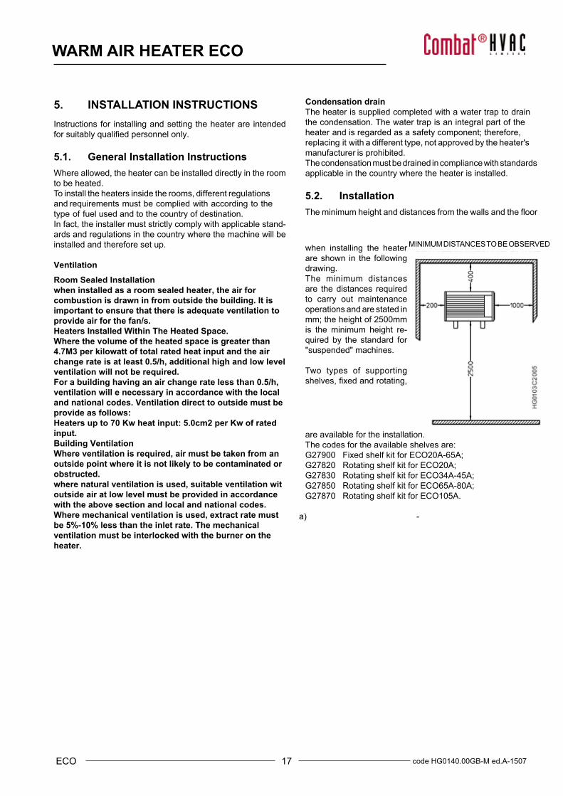
MINIMUM DISTANCES TO BE OBSERVED
Condensation drainThe heater is supplied completed with a water trap to drain the condensation. The water trap is an integral part of the heater and is regarded as a safety component; therefore, replacing it with a different type, not approved by the heater's manufacturer is prohibited.The condensation must be drained in compliance with standards applicable in the country where the heater is installed.
5.2. InstallationTheminimumheightanddistancesfromthewallsandthefloor
are available for the installation.The codes for the available shelves are:G27900 Fixed shelf kit for ECO20A-65A;G27820 Rotating shelf kit for ECO20A;G27830 Rotating shelf kit for ECO34A-45A;G27850 Rotating shelf kit for ECO65A-80A;G27870 Rotating shelf kit for ECO105A.
when installing the heaterare shown in the following drawing. The minimum distances are the distances required to carry out maintenance operations and are stated in mm; the height of 2500mm is the minimum height re-quired by the standard for "suspended" machines.
Two types of supporting shelves,fixedandrotating,

18code HG0140.00GB-M ed.A-1507 ECO
WARM AIR HEATER ECO
HG140.00_IM_030
HG140.00_IM_039
Suspended heaterECO20A-80A HEATERS: To install a suspended heater by using eyebolts, tie rods or chains, a kit containing supporting pins is available, as an accessory; its code is: G27880. This kit is suitable for all ECO models and does not include eyebolts (optionalaccessorycodeX00728).
HG140.00_IM_006
Fixed shelvesToinstallthefixedshelvestothewalls:
• fixittothewallandlevelthebracketwithaspiritlevel: ---------------------------------------------------------------------------------NOTE: make sure that the screws and wall plugs are suitably sized for the type of wall and that they can withstand the heater weight. -----------------------------------------------------------------------------------• Place the suspended heater by centering it on the brackets in order to match the holes on the heater with the holes on the brackets, taking into account that, for all models, thetipsofthebracketsareflushwiththeedge ofthe suspended heater;• Usethepapertemplate suppliedto mark the holes tofixthe bracketstothewall;• Fix the heater in position by using the M8 supplied as standard, inserting locking washer between the screw and the bracket.
code HG0140.00GB-M ed.A-1507
HG140.00_IM_041
PLATE TO TIE THE HEATER TO PILLARcod. G27835
Rotating shelvesThe instructionsonhow tofit the rotatingshelfandapapertemplate to position the shelf onto the wall can be found inside the shelf packaging.Using rotating shelves is recommended in the following cases:
a) whenfittingtheheaterontoacorner;b) whenfittingtheshelfontoapole;c)whenfittingtheheateratarightanglewiththewallitisfixedto.
19 code HG0140.00GB-M ed.A-1507ECO
WARM AIR HEATER ECO
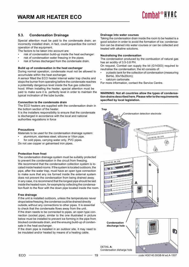
Trap
Condensationdischarge hole
Condensation detection electrode
HG140.00_IM_011
HG140.00_IM_015
HG140.00_IM_038
DETAIL A: Condensation disharge hole
A
5.3. Condensation Drainage Special attention must be paid to the condensate drain; an incorrectly installed drain, in fact, could jeopardize the correct operation of the equipment.The factors to be taken into account are:• risk of condensation build-up inside the heat exchanger:• risk of condensation water freezing in the pipes;• risk of fumes discharged from the condensate drain.
Build up of condensation in the heat exchangerDuring normal operation, condensate must not be allowed to accumulate within the heat exchanger.AsensorfittedtheECOheaterinternalwatertrapchecksandstops the burner from operating before the condensate reaches a potentially dangerous level inside the flue gas collection hood. When installing the heater, special attention must be paid to make sure it is perfectly level in order to maintain the typical inclination of the tube bundle.
Connection to the condensate drainThe ECO heaters are supplied with the condensation drain in the bottom section of the heater.It is the installers responsibility to ensure that the condensate is discharged in accordance with the local and national authorities regulations in force
•
PrecautionsMaterials to be used for the condensation drainage system:• aluminium, stainless steel, silicone or Viton pipe.• for cold pipes, carrying water only, PVC pipes.Do not use copper or galvanised iron pipes.
Protection from frostThe condensation drainage system must be suitably protected to prevent the condensation in the circuit from freezing.We recommend that the condensation collection system is lo-cated inside heated rooms. If the system is located outdoors, the pipe, after the water trap, must have an open type connection to make sure that any ice formed inside the external system does not prevent the condensation from being drained away. In any case, it is recommend that the longest pipe should be laid inside the heated room, for example by collecting the condensa-tionflushtothefloorwiththedownpipelocatedinsidetheroom.
Free drainageIf the unit is installed outdoors, unless the temperatures never drops below freezing, the condense could be drained directly outside, without any connections to other pipes. It is essential to check thatthecondensateflowsawayfromtheunit.If the drain needs to be connected to pipes, an open type con-nection(socketpipe),similar to theone illustrated inpicturebelow must be installed to prevent ice forming in the pipe from blocked condensate drain, and the ensuing build-up of conden-sate in the heat exchanger. If the drain pipe is installed in an outdoor site, it may need to be insulated and/or heated by means of a heating cable.
Drainage into water coursesTaking the condensation drain inside the room to be heated is a good solution in order to avoid the formation of ice; condensa-tion can be drained into water courses or can be collected and treated with alkaline solutions.
Neutralising the condensationThe condensation produced by the combustion of natural gas has an acidity of 3.5-3.8 PH.Onrequest,Combatcansupplythekit(G14303)requiredtoneutralise the condensation; the kit consists of:• a plastic tank for the collection of condensation (measuring
BxHxL30x18x20cm);• calcium carbonate.For more information, contact the Service Centre.
----------------------------------------------------------------------------------WARNING: Not all countries allow the types of condensa-tion drains described here. Please refer to the requirements specified by local legislation.----------------------------------------------------------------------------------

20code HG0140.00GB-M ed.A-1507 ECO
WARM AIR HEATER ECO
5.4. Connections to the FlueTheECOheatersarefittedwithawatertightcombustioncircuitand with a fan located upstream of the heat exchanger. Connectiontotheflue,accordingtowheretheheaterisinstalled,can be made as "C" type, with combustion air being drawn from outside, or as "B" type with combustion air being drawn from the heater installation site.Morespecifically,theheateriscertifiedforthefollowingexhausts:C13-C33-C53-C63-B23.Certifiedpipesandterminalsmustbeused.The air intake terminals and flue exhausts must prevent ac-cess to a ball with a diameter higher than or equal to 12 mm.
COMBAT sells certified intake or exhaust terminals that must therefore be bought together with the heaters.
TheECOheatersaresuppliedasstandardwithhorizontalfit-tings,flueandairintake,locatedinthebackoftheheater.It is possible, even during the installation stage, to move the flue exhaustandairintakefittingstothetopoftheheater;thisisusefulwhentheexhaustisfittedtotheroof.On request, and according to the quantity, the heater can be providedwithfittingsinthetopsectiontofitaverticalexhaust. To make the flue exhaust, taking into account that the ECO heaters are of a condensing type, the following material must be used.• Aluminium with a thickness higher than or equal to 1.5 mm;• - stainless steel with a thickness of at least 0.6 mm; the
steelmusthaveacarboncontentofatleast0.2%.Pipesfittedwithasealmustbeusedinordertopreventtheflue gases leaking from the pipes; the seal must be suitable to withstand flue temperatures ranging between 25°C and 210°C for ECO heaters. ----------------------------------------------------------------------------------WARNING: Using plastic materials on flue exhaust ducting is strictly prohibited. ----------------------------------------------------------------------------------ForECOheaters, the fluedoesnotneed tobe insulated toprevent the formation of condensation in the pipe, as this will notaffecttheheater,whichisfittedwithawatertrap. ----------------------------------------------------------------------------------IMPORTANT: The horizontal sections of flue must be in-stalled with a slightly incline (1°- 3°) towards the heater, in order to prevent the build up of condensation in the exhaust. ---
Protect the pipe with a guard if required to protect the flue from accidental contact.For the air intake, use:
• Aluminium with a thickness of at least 1.0 mm;• Stainless steel with a thickness of at least 0.4 mm;
Selection GuideThe table showing the flue exhaust system calculation data can be found in Paragraph 7.2 "Gas settings data table". Themaximumrecirculationpercentageis11%.
The tables below show the pressure drop for Ø 80 and Ø 100 terminals and exhaust ducting.If the terminal is not directly connected to the heater and, therefore, extra routing is required, according to the length of the ducting, the diameter of the selected terminals, extensions and bends must be checked.After establishing the routing, the pressure drop must be calcu-lated for each component by referring to the tables below accord-ing to the ECO heater used; each component has a different pressuredropvalueasthegluegasesflowrateisdifferent. Add together the pressure drops of the single components, checking that the result is not higher than the available value for the heater to be used. If a combustion air supply pipe is fitted,thepressurelossesmustbeaddedtotheflueexhaustpressure dropIf the sum of pressure drop is higher than the pressure avail-able, ducting with higher diameter must be used, rechecking the calculation; a pressure drop higher than the pressure available at the flue exhaust reduces the heater module heat output. ----------------------------------------------------------------------------------NOTE: If the module is installed indoor:• using coaxial connections is allowed for heaters for a pipe
length not exceeding 3 metres;• the flue exhaust terminal must be installed in compliance
with reference national regulation requirements.----------------------------------------------------------------------------------NOTE: The following pictures show examples of flue exhaust and air intake that can be created by using the kits available from the catalogue; the table shows the pipe maximum lengths between the heater and the terminal. If the duct routing requires the use of bends, the length required must be subtracted from the available length:Bend Ø 80 90° EqL1.65 mBend Ø 80 45° EqL0.80 mBend Ø 100 90° EqL0.2.30 mBend Ø 100 45° EqL0.1.03 m* Valid equivalent lengths for wide radius bends.----------------------------------------------------------------------------------
21 code HG0140.00GB-M ed.A-1507ECO
WARM AIR HEATER ECO
NOTE:ValuescalculatedonthefluemassflowrateachievedwithnaturalgasG20.
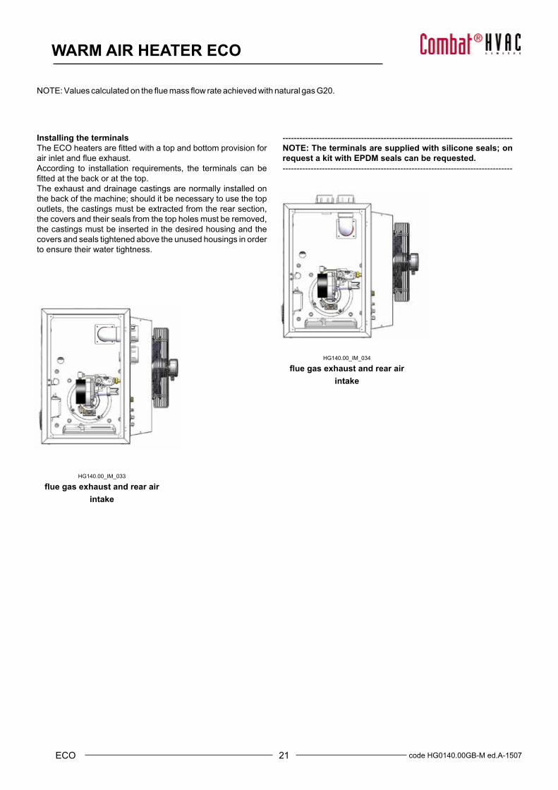
Installing the terminalsTheECOheatersarefittedwithatopandbottomprovisionforair inlet and flue exhaust.According to installation requirements, the terminals can be fittedatthebackoratthetop.The exhaust and drainage castings are normally installed on the back of the machine; should it be necessary to use the top outlets, the castings must be extracted from the rear section, the covers and their seals from the top holes must be removed, the castings must be inserted in the desired housing and the covers and seals tightened above the unused housings in order to ensure their water tightness.
HG140.00_IM_033
flue gas exhaust and rear air intake
HG140.00_IM_034
flue gas exhaust and rear air intake
----------------------------------------------------------------------------------NOTE: The terminals are supplied with silicone seals; on request a kit with EPDM seals can be requested.----------------------------------------------------------------------------------
22code HG0140.00GB-M ed.A-1507 ECO
WARM AIR HEATER ECO
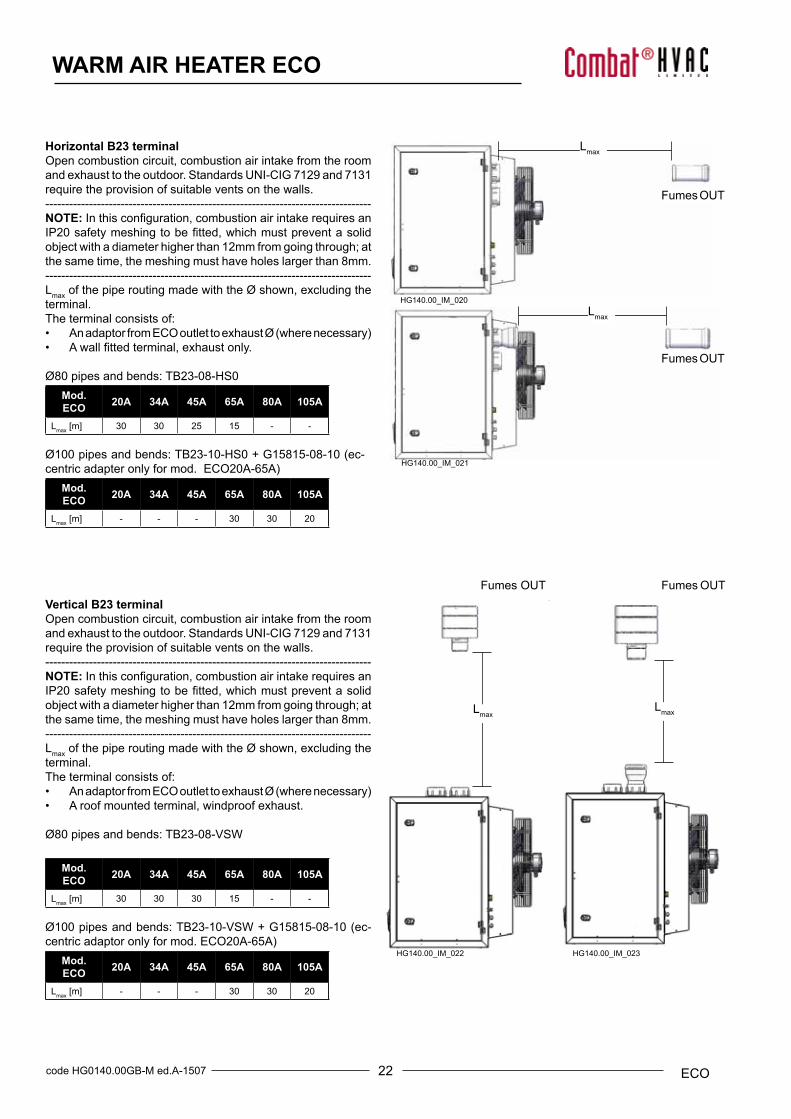
Horizontal B23 terminalOpen combustion circuit, combustion air intake from the room and exhaust to the outdoor. Standards UNI-CIG 7129 and 7131 require the provision of suitable vents on the walls.----------------------------------------------------------------------------------NOTE:Inthisconfiguration,combustionairintakerequiresanIP20safetymeshingtobefitted,whichmustpreventasolidobject with a diameter higher than 12mm from going through; at the same time, the meshing must have holes larger than 8mm.----------------------------------------------------------------------------------Lmax of the pipe routing made with the Ø shown, excluding the terminal.The terminal consists of:• AnadaptorfromECOoutlettoexhaustØ(wherenecessary)• Awallfittedterminal,exhaustonly.
Ø80 pipes and bends: TB23-08-HS0Mod. ECO 20A 34A 45A 65A 80A 105A
Lmax [m] 30 30 25 15 - -
Ø100 pipes and bends: TB23-10-HS0 + G15815-08-10 (ec-centricadapteronlyformod.ECO20A-65A)
Mod. ECO 20A 34A 45A 65A 80A 105A
Lmax [m] - - - 30 30 20
Vertical B23 terminalOpen combustion circuit, combustion air intake from the room and exhaust to the outdoor. Standards UNI-CIG 7129 and 7131 require the provision of suitable vents on the walls.----------------------------------------------------------------------------------NOTE:Inthisconfiguration,combustionairintakerequiresanIP20safetymeshingtobefitted,whichmustpreventasolidobject with a diameter higher than 12mm from going through; at the same time, the meshing must have holes larger than 8mm.----------------------------------------------------------------------------------Lmax of the pipe routing made with the Ø shown, excluding the terminal.The terminal consists of:• AnadaptorfromECOoutlettoexhaustØ(wherenecessary)• A roof mounted terminal, windproof exhaust.
Ø80 pipes and bends: TB23-08-VSW
Mod. ECO 20A 34A 45A 65A 80A 105A
Lmax [m] 30 30 30 15 - -
Ø100 pipes and bends: TB23-10-VSW + G15815-08-10 (ec-centricadaptoronlyformod.ECO20A-65A)
Mod. ECO 20A 34A 45A 65A 80A 105A
Lmax [m] - - - 30 30 20
HG140.00_IM_021
Lmax
Fumes OUT
Lmax
Fumes OUT
Lmax
Fumes OUT
Lmax
Fumes OUT
HG140.00_IM_020
HG140.00_IM_022 HG140.00_IM_023
23 code HG0140.00GB-M ed.A-1507ECO
WARM AIR HEATER ECO
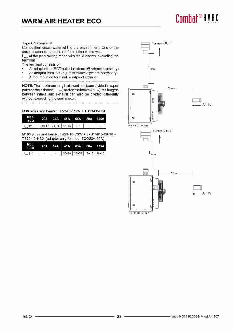
Type C53 terminal Combustion circuit watertight to the environment. One of the ducts is connected to the roof, the other to the wall.Lmax of the pipe routing made with the Ø shown, excluding the terminal.The terminal consists of:• AnadaptorfromECOoutlettoexhaustØ(wherenecessary)• AnadaptorfromECOoutlettointakeØ(wherenecessary);• A roof mounted terminal, windproof exhaust.----------------------------------------------------------------------------------NOTE: The maximum length allowed has been divided in equal parts on the exhaust (L1max)andontheintake(L2max);thelengthsbetween intake and exhaust can also be divided differentlywithout exceeding the sum shown.----------------------------------------------------------------------------------
Ø80 pipes and bends: TB23-08-VSW + TB23-08-HS0Mod. ECO 20A 34A 45A 65A 80A 105A
Lmax [m] 30+30 20+20 15+15 8+8 - -
Ø100 pipes and bends: TB23-10-VSW + 2xG15815-08-10 + TB23-10-HS0(adaptoronlyformod.ECO20A-65A)
Mod. ECO 20A 34A 45A 65A 80A 105A
Lmax [m] - - 30+30 25+25 15+15 10+10
L1max
L2max
Air IN
Fumes OUT
L1max
L2max
Air IN
Fumes OUTHG140.00_IM_026
HG140.00_IM_027

24code HG0140.00GB-M ed.A-1507 ECO
WARM AIR HEATER ECO
Horizontal coaxial C13 terminalCombustion circuit watertight to the environment. The ducts go directly through the wall.Lmax of the pipe routing made with the Ø shown, excluding the terminal.The terminal consists of:• AnadaptorfromECOoutlettoexhaustØ(wherenecessary)• AnadaptorfromECOoutlettointakeØ(wherenecessary);• A horizontal coaxial terminal.----------------------------------------------------------------------------------NOTE: The maximum length allowed has been divided in equal parts on the exhaust (L1max)andontheintake(L2max);thelengthsbetween intake and exhaust can also be divided differentlywithout exceeding the sum shown.----------------------------------------------------------------------------------
Ø80 pipes and bends: TC13-08-HC1Mod. ECO 20A 34A 45A 65A 80A 105A
Lmax [m] 30+30 30+30 15+15 5+5 - -
Ø100 pipes and bends: TC13-10-HC2 + 2xG15835-08-10 (ec-centricadaptorsonlyformod.ECO20A-65A)
Mod. ECO 20A 34A 45A 65A 80A 105A
Lmax [m] - - 30+30 15+15 5+5 1+1
Ø130 pipes and bends: TC13-13-HC5 + 2xG15815-10-13 + 2xG15810-13-45 (adaptors and bends only suitable only for modelECO80A-105A)
Mod. ECO 20A 34A 45A 65A 80A 105A
Lmax [m] - - - - 30+30 30+30
L1max
L2max
L1max
L2max
HG140.00_IM_024
HG140.00_IM_025
25 code HG0140.00GB-M ed.A-1507ECO
WARM AIR HEATER ECO
L1maxL2max
L1maxL2max
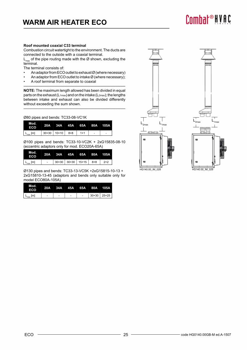
Roof mounted coaxial C33 terminalCombustion circuit watertight to the environment. The ducts are connected to the outside with a coaxial terminal.Lmax of the pipe routing made with the Ø shown, excluding the terminal.The terminal consists of:• AnadaptorfromECOoutlettoexhaustØ(wherenecessary)• AnadaptorfromECOoutlettointakeØ(wherenecessary);• A roof terminal from separate to coaxial----------------------------------------------------------------------------------NOTE: The maximum length allowed has been divided in equal parts on the exhaust (L1max)andontheintake(L2max);thelengthsbetween intake and exhaust can also be divided differentlywithout exceeding the sum shown.----------------------------------------------------------------------------------
Ø80 pipes and bends: TC33-08-VC1KMod. ECO 20A 34A 45A 65A 80A 105A
Lmax [m] 30+30 10+10 8+8 1+1 - -
Ø100 pipes and bends: TC33-10-VC2K + 2xG15835-08-10 (eccentricadaptorsonlyformod.ECO20A-65A)
Mod. ECO 20A 34A 45A 65A 80A 105A
Lmax [m] - 30+30 30+30 15+15 8+8 2+2
Ø130 pipes and bends: TC33-13-VC5K +2xG15815-10-13 + 2xG15810-13-45 (adaptors and bends only suitable only for modelECO80A-105A)
Mod. ECO 20A 34A 45A 65A 80A 105A
Lmax [m] - - - - 30+30 25+25
HG140.00_IM_028 HG140.00_IM_029
26code HG0140.00GB-M ed.A-1507 ECO
WARM AIR HEATER ECO
Power supplysocket
TA
C09660I/0RS
SB[24Vdc]
HC0047 C2 009
1
R20
F9
R56
C26
Q1
R8
CN
15R
104
R22
R87
C49
F5
D6
C50
C32
R39
U15
C41
Q2
CN
11
R48
U1
CN
12
C28
R61
R24
U8
C21F3
R3
R50
R27
F4
U2
R16
R1
U4
R29
CN04
C42
R44
R66
F6
R52
TP1
R83
R4
R73
R101
C54
C55
C18
R17
U9
R65
R2R91
C35
R97
C6
OP1
L1
DZ1
C1
T2
D11
D16
C12
R90
C34
R103
F1
D7R
37
R7
R18
R74
CN13
D17
R5C37
R99
C31
C2
SW1
R94
C52
R34
U3F8
C56
R89
C14
R25
F2
R106
R77
R43
C27
R49
R10
R58
C40
C20
C8
Q5
R45
R62
RL2
C22
R64
D3
C23
CN01
LC1R
32RL1
C51
U11
LC6
C11
R70
R41
R40D9
D1
R35
R110
R42
R31
R59
R96
TS1
R38
D5
D20
Q3R23
D2
R55
R26
CN02
D10
C29
R100
C15
C33
D13
R19
R78 R108
R102
R76
R79
D8
C43
TS2
C5
C10
R9
U14
LC5
LC2
C38
C17
Q6
VR1
CN
08
C3
R71
R95
R72
R12
T1
C36
C53
R107
U5
D4
R82
XT1
C48
F7
R88
C30
R28
R14
C39
R63
R54
R11
U13
R53
C46
RR1
C16 C45
R109
R13
C44
CN06
LC3
J1
U10
R30
R57
R15
R21
R36
CN
14
R98
R86
R60
C9
D14
D19
D12
R69
CN07
R84
C7
D15
D21
R93
RD1
C47
R105
R81
LC4
R47
R67
R92
R51
R68
Q4R85
R75
CN
05
C25
U12
CN03
C13
R6
R80
R33
C4
D18
LFN
+5V
B3GND+5
VB2GN
D
B1GN
D
NTC3
NTC3
N
NTC2
NTC2NTC1
NTC1
D-D+
GND
+12V
+28V
HALL
L1
PWM
GND ID
2
IDC
2
ID3
IDC
4
ID4
IDC
5ID
5
IDC
6
N
ID6
+28V Y2 Y1 G
ND Q2
CO
M
N.C.
N.O
.
N
N
L
GND
7Vdc
24Vac
24Vdc
CLK
DAT
NC
IDC1 ID1
LBW
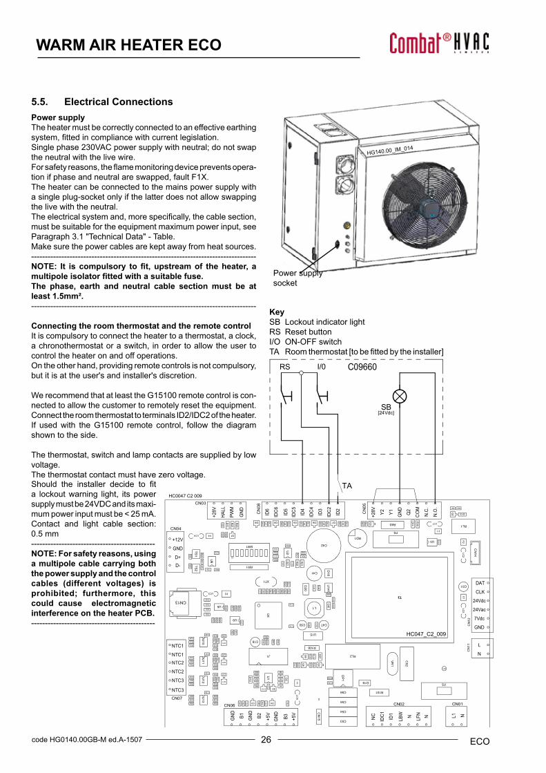
KeySB Lockout indicator lightRS Reset buttonI/O ON-OFF switchTA Roomthermostat[tobefittedbytheinstaller]
HG140.00_IM_014
HC047_C2_009
5.5. Electrical ConnectionsPower supplyThe heater must be correctly connected to an effective earthing system,fittedincompliancewithcurrentlegislation.Single phase 230VAC power supply with neutral; do not swap the neutral with the live wire.Forsafetyreasons,theflamemonitoringdevicepreventsopera-tion if phase and neutral are swapped, fault F1X.The heater can be connected to the mains power supply with a single plug-socket only if the latter does not allow swapping the live with the neutral.Theelectricalsystemand,morespecifically,thecablesection,must be suitable for the equipment maximum power input, see Paragraph 3.1 "Technical Data" - Table.Make sure the power cables are kept away from heat sources.----------------------------------------------------------------------------------NOTE: It is compulsory to fit, upstream of the heater, a multipole isolator fitted with a suitable fuse.The phase, earth and neutral cable section must be at least 1.5mm².----------------------------------------------------------------------------------
Connecting the room thermostat and the remote controlIt is compulsory to connect the heater to a thermostat, a clock, a chronothermostat or a switch, in order to allow the user to control the heater on and off operations.On the other hand, providing remote controls is not compulsory, but it is at the user's and installer's discretion.
We recommend that at least the G15100 remote control is con-nected to allow the customer to remotely reset the equipment.Connect the room thermostat to terminals ID2/IDC2 of the heater. If used with the G15100 remote control, follow the diagram shown to the side.
The thermostat, switch and lamp contacts are supplied by low voltage.The thermostat contact must have zero voltage.Should the installer decide to fita lockout warning light, its power supply must be 24VDC and its maxi-mum power input must be < 25 mA.Contact and light cable section: 0.5 mm---------------------------------------------NOTE: For safety reasons, using a multipole cable carrying both the power supply and the control cables (different voltages) is prohibited; furthermore, this could cause electromagnetic interference on the heater PCB.---------------------------------------------
27 code HG0140.00GB-M ed.A-1507ECO
WARM AIR HEATER ECO
ProbeInternal
Remoteprobe(ambient)temperature - optional (code
G07202)
7÷25
Vcc
0 V
V+ gnd I3A+ B- I2I1NTC
MOD-BUS connection
Power supply connection
Remote ON/OFF contact
A
DETTAGLIO A
+12VGND D+ D-
A
DETTAGLIO A
+12VGND D+ D-
A
DETTAGLIO A
+12V GND D+ D-
CPU-SMART#1
CPU-SMART#2
CPU-SMART#n
Setting switchHeater address
Contacts jumper ID2-IDC2
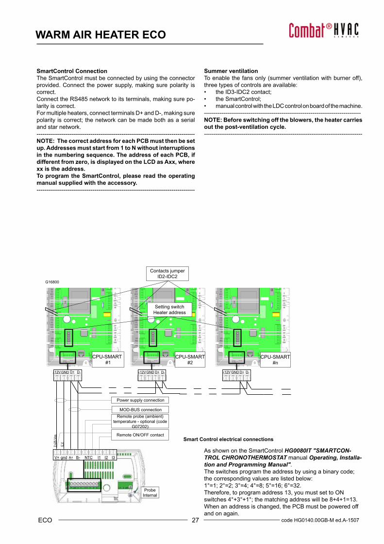
Smart Control electrical connections
As shown on the SmartControl HG0080IT "SMARTCON-TROL CHRONOTHERMOSTAT manual Operating, Installa-tion and Programming Manual".The switches program the address by using a binary code; the corresponding values are listed below:1°=1; 2°=2; 3°=4; 4°=8; 5°=16; 6°=32.Therefore, to program address 13, you must set to ON switches 4°+3°+1°; the matching address will be 8+4+1=13.When an address is changed, the PCB must be powered off and on again.
G16800
SmartControl ConnectionThe SmartControl must be connected by using the connector provided. Connect the power supply, making sure polarity is correct. Connect the RS485 network to its terminals, making sure po-larity is correct.For multiple heaters, connect terminals D+ and D-, making sure polarity is correct; the network can be made both as a serial and star network. ----------------------------------------------------------------------------------NOTE: The correct address for each PCB must then be set up. Addresses must start from 1 to N without interruptions in the numbering sequence. The address of each PCB, if different from zero, is displayed on the LCD as Axx, where xx is the address.To program the SmartControl, please read the operating manual supplied with the accessory.----------------------------------------------------------------------------------
Summer ventilationToenablethefansonly(summerventilationwithburneroff),three types of controls are available:• the ID3-IDC2 contact;• the SmartControl;• manual control with the LDC control on board of the machine.---------------------------------------------------------------------------------NOTE: Before switching off the blowers, the heater carries out the post-ventilation cycle.------------------------------------------------------------------------------------
28code HG0140.00GB-M ed.A-1507 ECO
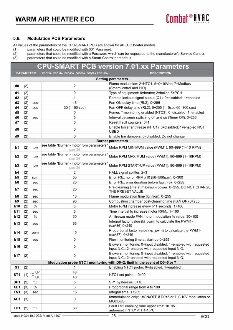
WARM AIR HEATER ECO
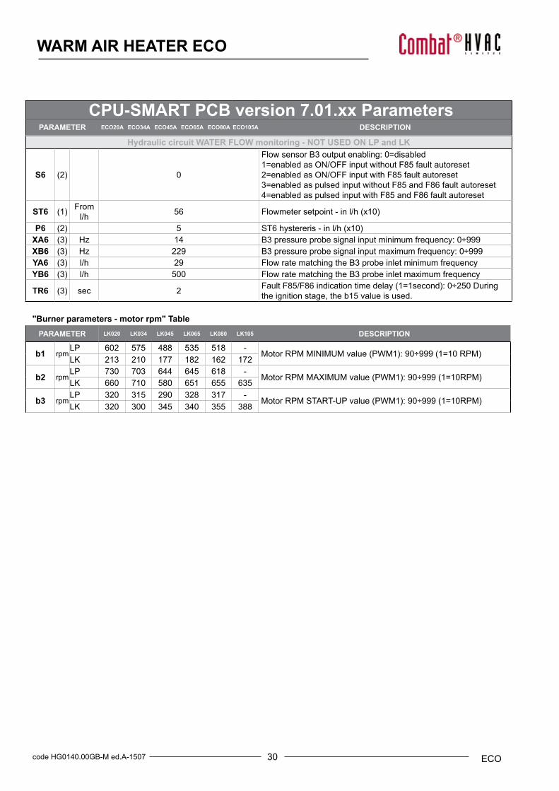
CPU-SMART PCB version 7.01.xx ParametersPARAMETER ECO20A ECO34A ECO45A ECO65A ECO80A ECO105A DESCRIPTION
Setting parameters
d0 (2) 2 Flame modulation: 2=NTC1; 5=0÷10Vdc; 7=Modbus (SmartControlandPID)
d1 (2) 0 Type of equipment: 0=heater; 2=boiler; 5=PCHd2 (2) 1 Remotelockoutsignaloutput(Q1):0=disabled;1=enabledd3 (2) sec 45 FanONdelaytime(RL2):0÷255d4 (2) sec 30(=150sec) FanOFFdelaytime(RL2):0÷255(1=5sec60=300sec)d5 (2) 0 FumesTmonitoringenabled(NTC3):0=disabled;1=enabledd6 (2) sec 5 Intervalbetweenswitchingoffandon(TimerOff):0÷255d7 (2) 0 Reset Fault counters: 0÷1
d8 (2) 0 Enableboilerantifreeze(NTC1):0=disabled;1=enabledNOTUSED
d9 (2) 0 Enablefiredampers:0=disabled;DonotchangeBurner parameters
b1 (2) rpm see table "Burner - motor rpm parameters" pae 34 MotorRPMMINIMUMvalue(PWM1):90÷999(1=10RPM)
b2 (2) rpm see table "Burner - motor rpm parameters" pae 34 MotorRPMMAXIMUMvalue(PWM1):90÷999(1=10RPM)
b3 (2) rpm see table "Burner - motor rpm parameters" pae 34 MotorRPMSTART-UPvalue(PWM1):90÷999(1=10RPM)
b4 (2) 2 HALL signal splitter: 2÷3b5 (2) rpm 50 ErrorF3x;no.ofRPMx10(50=500rpm):0÷300b6 (2) sec 20 Error F3x; error duration before fault F3x: 0÷255
b7 (2) sec 20 Pre-cleaning time at maximum power: 0÷255. DO NOT CHANGE THE PRESET VALUE
b8 (2) sec 10 Flamemodulationtime(ignition):0÷255b9 (2) sec 90 Combustionchamberpost-cleaningtime(FANON)0÷255b10 (2) % 5 Motor RPM increase every b11 seconds: 1÷100b11 (2) sec 5 Time interval to increase motor RPM:: 1÷100b12 (2) % 30 AntifreezemodeFANmotormodulation%value:30÷100
b13 (2) sec 65 Integralfactorvalue(ki_pwm)tocalculatethePWM1-(exA36):0÷249
b14 (2) pem 45 Proportionalfactorvalue(kp_pwm)tocalculatethePWM1-(exA37):0÷249
b15 (2) sec 0 Flow monitoring time at start-up 0÷255
b16 (2) 0 Blowers monitoring: 0=input disabled; 1=enabled with requested input N.C.; 2=enabled with requested input N.O.
b17 (2) 0 Blowers monitoring: 0=input disabled; 1=enabled with requested input N.C.; 2=enabled with requested input N.O.
Modulation probe NTC1 monitoring with D0=2; limit in the event of D0=5 or 7S1 (2) 1 Enabling NTC1 probe: 0=disabled; 1=enabled
ST1 (1) °CLP 48
NTC1 set point: -10÷90 LK 40
SP1 (2) °C 5 SP1 hysteresis: 0÷10XD1 (3) % 6 Proportional range from 4 to 100TN1 (3) sec 15 Integral time: 1÷255
AC1 (3) 0 0=modulation only; 1=ON/OFF if D0=5 or 7, 0/10V modulation or MODBUS
TH1 (2) °C 60 Fault F51 enabling time upper limit: 10÷95autoreset if NTC1<TH1-15°C
5.6. Modulation PCB Parameters All values of the parameters of the CPU-SMART PCB are shown for all ECO heater models.(1) parametersthatcouldbemodifiedwith001Password;(2) parametersthatcouldbemodifiedwithaPasswordwhichcanberequestedtothemanufacturer'sServiceCentre;(3) parametersthatcouldbemodifiedwithaSmartControlormodbus.
29 code HG0140.00GB-M ed.A-1507ECO
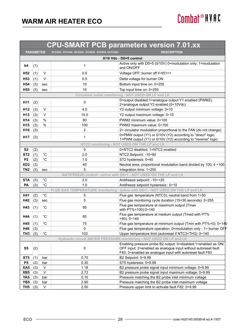
WARM AIR HEATER ECO
CPU-SMART PCB parameters version 7.01.xxPARAMETER ECO20A ECO34A ECO45A ECO65A ECO80A ECO105A DESCRIPTION
0/10 Vdc - D0=5 control
b4 (1) 1 ActiveonlywithD0=5(0/10V)0=modulationonly;1=modulationand ON/OFF
H52 (1) V 0.5 Voltage OFF; burner off if H51=1H53 (1) V 0.5 Delta voltage for burner ONH54 (3) sec 10 Bottom input time on: 0÷255H55 (3) sec 10 Top input time on: 0÷255
Circulator outlet monitoring - NOT USED ON LP and LK
H11 (2) 0 0=outputdisabled;1=analogueoutputY1enabled(PWM2);2=analogueoutputY2enabled(0÷10Vdc)
H12 (3) V 4.0 Y2 output minimum voltage: 0÷10H13 (3) V 10.0 Y2 output maximum voltage: 0÷10H14 (3) % 80 PWM2 minimum value: 0÷100H15 (3) % 100 PWM2 maximum value: 0÷100H16 (3) 2 2=circulatormodulationproportionaltotheFAN(donotchange)
H17 (3) 1 0=PMWoutput(Y1)or0/10V(Y2)accordingto"direct"logic;1=PWMoutput(Y1)or0/10V(Y2)accordingto"reverse"logic:
NTC2 monitoring - NOT USED ON THE LP and LKS2 (2) 0 0=NTC2 disabled; 1=NTC2 enabled
ST2 (1) °C 2.0 NTC2 Setpoint: -10÷90P2 (2) °C 1.0 ST2 hysteresis: 0÷40
XD2 (3) 40 Neutral area, proportional modulation band divided by 100; 4 ÷100 TN2 (3) sec 5 Integration time: 1÷255
ANTIFREEZE control - active with D8=1 - NOT USED ON THE LP and LKSTA (3) °C 2.0 Antifreeze setpoint: -10÷+20PA (3) °C 1.0 Antifreeze setpoint hysteresis:: 0÷10
FLUE GAS TEMPERATURE monitoring - active with D8=1 - NOT USED ON THE LP and LKH41 (2) °C 5 Flue gas temperature(NTC3);neutralbandfrom1÷50H42 (3) sec 5 Flue gasmonitoringcycleduration(15=30seconds):0÷255
H43 (1) °C 95 Flue gas temperature at maximum output (Tmax with PT%=100):0÷140
H44 (1) °C 85 Flue gastemperatureatmediumoutput(TmedwithPT%=50):0÷140
H45 (1) °C 75 Flue gastemperatureatminimumoutput(TminwithPT%=0):0÷140H46 (3) 0 Flue gas temperature operation: 0=modulation only - 1= burner OFF TH3 (3) °C 103 Uppertemperaturelimit(autoresetifNTC3<TH3):0÷140
Hydraulic circuit WATER PRESSURE monitoring - NOT USED ON LP and LK
S5 (2) 0Enabling pressure probe B2 output: 0=disabled;1=enabled as ON/OFF input; 2=enabled as analogue input without autoreset fault F83; 3=enabled as analogue input with autoreset fault F83
ST5 (1) bar 0.70 B2 Setpoint: 0÷9.99P5 (2) bar 0.30 ST5 hysteresis: 0÷9.99
XA5 (3) V 1.18 B2 pressure probe signal input minimum voltage: 0÷9.99XB5 (3) V 2.72 B2 pressure probe signal input maximum voltage: 0÷9.99YA5 (3) bar 0.10 Pressure matching the B2 probe inlet minimum voltageYB5 (3) bar 2.90 Pressure matching the B2 probe inlet maximum voltageTH5 (3) V 2.50 Pressure upper limit to activate fault F82: 0÷9.99
30code HG0140.00GB-M ed.A-1507 ECO
WARM AIR HEATER ECO
Hydraulic circuit WATER FLOW monitoring - NOT USED ON LP and LK
S6 (2) 0
Flow sensor B3 output enabling: 0=disabled1=enabled as ON/OFF input without F85 fault autoreset2=enabled as ON/OFF input with F85 fault autoreset3=enabled as pulsed input without F85 and F86 fault autoreset4=enabled as pulsed input with F85 and F86 fault autoreset
ST6 (1) From l/h 56 Flowmetersetpoint-inl/h(x10)
P6 (2) 5 ST6hystereris-inl/h(x10)XA6 (3) Hz 14 B3 pressure probe signal input minimum frequency: 0÷999XB6 (3) Hz 229 B3 pressure probe signal input maximum frequency: 0÷999YA6 (3) l/h 29 Flow rate matching the B3 probe inlet minimum frequencyYB6 (3) l/h 500 Flow rate matching the B3 probe inlet maximum frequency
TR6 (3) sec 2 FaultF85/F86indicationtimedelay(1=1second):0÷250Duringthe ignition stage, the b15 value is used.
"Burner parameters - motor rpm" TablePARAMETER LK020 LK034 LK045 LK065 LK080 LK105 DESCRIPTION
b1 rpmLP 602 575 488 535 518 -
MotorRPMMINIMUMvalue(PWM1):90÷999(1=10RPM)LK 213 210 177 182 162 172
b2 rpmLP 730 703 644 645 618 -
MotorRPMMAXIMUMvalue(PWM1):90÷999(1=10RPM)LK 660 710 580 651 655 635
b3 rpmLP 320 315 290 328 317 -
MotorRPMSTART-UPvalue(PWM1):90÷999(1=10RPM)LK 320 300 345 340 355 388
CPU-SMART PCB version 7.01.xx ParametersPARAMETER ECO20A ECO34A ECO45A ECO65A ECO80A ECO105A DESCRIPTION
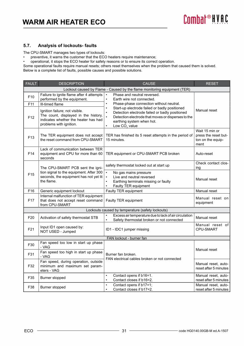
31 code HG0140.00GB-M ed.A-1507ECO
WARM AIR HEATER ECO
FAULT DESCRIPTION CAUSE RESETLockoutcausedbyFlame-Causedbytheflamemonitoringequipment(TER)
F10 Failuretoigniteflameafter4attemptsperformed by the equipment.
• Phase and neutral reversed.• Earth wire not connected.• Phase-phase connection without neutral.• Start-up electrode failed or badly positioned• Detection electrode failed or badly positioned• Detection electrode that moves or disperses to the
earthing system when hot.• Low CO2 value
Manual resetF11 Ill-timedflame
F12
Ignition failure; not visible.The count, displayed in the history, indicates whether the heater has had problems with ignition.
F13 The TER equipment does not accept the reset command from CPU-SMART
TERhasfinishedits5resetattemptsintheperiodof15 minutes.
Wait 15 min or press the reset but-ton on the equip-ment
F14Lack of communication between TER equipment and CPU for more than 60 seconds
TER equipment or CPU-SMART PCB broken Auto-reset
F15
The CPU-SMART PCB sent the igni-tion signal to the equipment. After 300 seconds, the equipment has not yet lit theflame.
safety thermostat locked out at start up Check contact clos-ing
• No gas mains pressure• Live and neutral reversed• Earthing terminals missing or faulty• Faulty TER equipment
Manual reset
F16 Generic equipment lockout Faulty TER equipment Manual reset
F17Internal malfunction of TER equipment that does not accept reset command from CPU-SMART
Faulty TER equipment Manual reset on equipment
Lockoutscausedbytemperature(safetylockouts)
F20 Activation of safety thermostat STB • Excess air temperature due to lack of air circulation• Safety thermostat broken or not connected Manual reset
F21 Input ID1 open caused by:NOT USED - Jumped ID1 - IDC1 jumper missing
Manual reset of CPU-SMART
FAN lockout - burner fan
F30 Fan speed too low in start up phase - VAG
Burner fan broken.FAN electrical cables broken or not connected
Manual resetF31 Fan speed too high in start up phase
- VAG
F32Fan speed, during operation, outside minimum and maximum set param-eters - VAG
Manual reset, auto-reset after 5 minutes
F35 Burner stopped • Contact opens if b16=1.• Contact closes if b16=2.
Manual reset, auto-reset after 5 minutes
F38 Burner stopped • Contact opens if b17=1;• Contact closes if b17=2.
Manual reset, auto-reset after 5 minutes
5.7. Analysis of lockouts- faultsThe CPU-SMART manages two types of lockouts:• preventive, it warns the customer that the ECO heaters require maintenance;• operational, it stops the ECO heater for safety reasons or to ensure its correct operation.Some operational faults require manual resets; others reset themselves when the problem that caused them is solved.Below is a complete list of faults, possible causes and possible solutions.
32code HG0140.00GB-M ed.A-1507 ECO
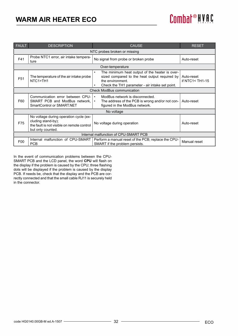
WARM AIR HEATER ECO
FAULT DESCRIPTION CAUSE RESETNTC probes broken or missing
F41 Probe NTC1 error, air intake tempera-ture No signal from probe or broken probe Auto-reset
Over-temperature
F51 The temperature of the air intake probe NTC1>TH1
• The minimum heat output of the heater is over-sized compared to the heat output required bythe environment.
• Check the TH1 parameter - air intake set point.
Auto-resetif NTC1< TH1-15
Check ModBus communication
F60Communication error between CPU-SMART PCB and ModBus network, SmartControl or SMART.NET
• ModBus network is disconnected.• The address of the PCB is wrong and/or not con-
figuredintheModBusnetwork.Auto-reset
No voltage
F75
No voltage during operation cycle (ex-cludingstand-by);the fault is not visible on remote control but only counted.
No voltage during operation Auto-reset
Internal malfunction of CPU-SMART PCB
F00 Internal malfunction of CPU-SMART PCB
Perform a manual reset of the PCB; replace the CPU-SMART if the problem persists. Manual reset
In the event of communication problems between the CPU-SMART PCB and the LCD panel, the word CPUwillflashonthedisplayiftheproblemiscausedbytheCPU;threeflashingdots will be displayed if the problem is caused by the display PCB. If needs be, check that the display and the PCB are cor-rectly connected and that the small cable RJ11 is securely held in the connector.
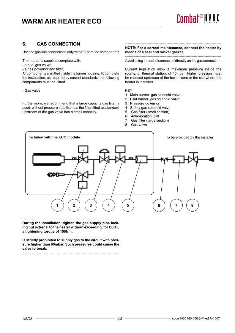
33 code HG0140.00GB-M ed.A-1507ECO
WARM AIR HEATER ECO
Included with the ECO module
2 5 6 7 81 2 3 4 5 6 7 8
To be provided by the installer
6. GAS CONNECTIONUsethegaslineconnectionsonlywithECcertifiedcomponents
The heater is supplied complete with:- a dual gas valve;- agasgovernorandfilter.Allcomponentsarefittedinsidetheburnerhousing.Tocompletethe installation, as required by current standards, the followingcomponentsmustbefitted
- Gas valve
Furthermore,werecommendthatalargecapacitygasfilterisused,withoutpressurestabiliser,asthefilterfittedasstandardupstream of the gas valve has a small capacity.
---------------------------------------------------------------------------------NOTE: For a correct maintenance, connect the heater by means of a seal and swivel gasket.---------------------------------------------------------------------------------Avoid using threaded connected directly on the gas connection.
Current legislation allow a maximum pressure inside the rooms, or thermal station, of 40mbar; higher pressure must be reduced upstream of the boiler room or the site where the heater is installed.
KEY1 Main burner gas solenoid valve2 Pilot burner gas solenoid valve3 Pressure governor4 Safety gas solenoid valve5Gasfilter(smallsection)6 Anti-vibration joint7Gasfilter(largesection)8 Gas valve
---------------------------------------------------------------------------------During the installation, tighten the gas supply pipe lock-ing nut external to the heater without exceeding, for Ø3/4'', a tightening torque of 150Nm.---------------------------------------------------------------------------------Is strictly prohibited to supply gas to the circuit with pres-sure higher than 60mbar. Such pressures could cause the valve to break.---------------------------------------------------------------------------------
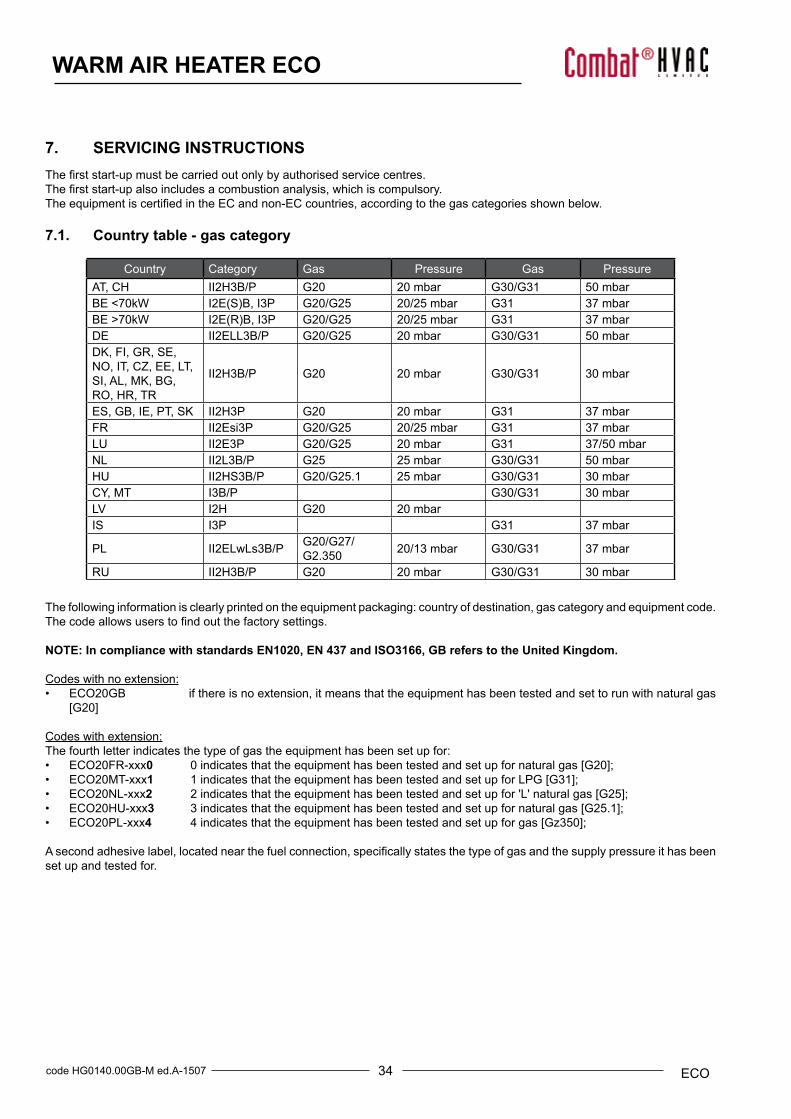
34code HG0140.00GB-M ed.A-1507 ECO
WARM AIR HEATER ECO
7. SERVICING INSTRUCTIONSThefirststart-upmustbecarriedoutonlybyauthorisedservicecentres.Thefirststart-upalsoincludesacombustionanalysis,whichiscompulsory.TheequipmentiscertifiedintheECandnon-ECcountries,accordingtothegascategoriesshownbelow.
7.1. Country table - gas category
Country Category Gas Pressure Gas PressureAT, CH II2H3B/P G20 20 mbar G30/G31 50 mbarBE <70kW I2E(S)B,I3P G20/G25 20/25 mbar G31 37 mbarBE >70kW I2E(R)B,I3P G20/G25 20/25 mbar G31 37 mbarDE II2ELL3B/P G20/G25 20 mbar G30/G31 50 mbarDK, FI, GR, SE, NO, IT, CZ, EE, LT, SI, AL, MK, BG, RO, HR, TR
II2H3B/P G20 20 mbar G30/G31 30 mbar
ES, GB, IE, PT, SK II2H3P G20 20 mbar G31 37 mbarFR II2Esi3P G20/G25 20/25 mbar G31 37 mbarLU II2E3P G20/G25 20 mbar G31 37/50 mbarNL II2L3B/P G25 25 mbar G30/G31 50 mbarHU II2HS3B/P G20/G25.1 25 mbar G30/G31 30 mbarCY, MT I3B/P G30/G31 30 mbarLV I2H G20 20 mbarIS I3P G31 37 mbar
PL II2ELwLs3B/P G20/G27/G2.350 20/13 mbar G30/G31 37 mbar
RU II2H3B/P G20 20 mbar G30/G31 30 mbar
The following information is clearly printed on the equipment packaging: country of destination, gas category and equipment code.Thecodeallowsuserstofindoutthefactorysettings.
NOTE: In compliance with standards EN1020, EN 437 and ISO3166, GB refers to the United Kingdom.
Codes with no extension:• ECO20GB if there is no extension, it means that the equipment has been tested and set to run with natural gas
[G20]
Codes with extension:The fourth letter indicates the type of gas the equipment has been set up for:• ECO20FR-xxx0 0 indicates that the equipment has been tested and set up for natural gas [G20];• ECO20MT-xxx1 1 indicates that the equipment has been tested and set up for LPG [G31];• ECO20NL-xxx2 2 indicates that the equipment has been tested and set up for 'L' natural gas [G25];• ECO20HU-xxx3 3 indicates that the equipment has been tested and set up for natural gas [G25.1];• ECO20PL-xxx4 4 indicates that the equipment has been tested and set up for gas [Gz350];
Asecondadhesivelabel,locatednearthefuelconnection,specificallystatesthetypeofgasandthesupplypressureithasbeenset up and tested for.

35 code HG0140.00GB-M ed.A-1507ECO
WARM AIR HEATER ECO
7.2. Gas settings tableTYPE OF GAS G20
TYPE OF EQUIPMENT ECO20A ECO34A ECO45A ECO65A ECO80A ECO105Amin max min max min max min max min max min max
CATEGORY according to the country of destination - see reference tableGAS SUPPLY PRESSURE [mbar] 20 [min 17-max 25] *Ø PILOT NOZZLE [mm] 0.7GAS CONSUMPTION (15°C-1013mbar) m3/h 0.51 2.01 0.80 3.69 0.90 4.44 1.31 6.88 1.74 8.68 1.90 10.6
CARBON DIOXIDE -CO2 CON-TENT [%] 8.8 9.1 8.7 9.1 8.7 9.1 8.7 9.1 8.7 9.1 8.5 9.1
FLUE GAS TEMPERATURE [°C] 38 111 31 94 30 93 31 86 26 70 28 80FLUE MASS FLOW RATE (MAX.) [kg/h] 31 57 72 107 135 165
GAS ORIFICE PLATE [mm] 4.4 6.4 7.2 10 9.7 Not required
AIR ORIFICE PLATE [mm] Not required
Not required
Not required
Not required
Not required
Not required
* For Hungary, the air supply pressure is 25 mbar
TYPE OF GAS G25TYPE OF EQUIPMENT ECO20A ECO34A ECO45A ECO65A ECO80A ECO105A
min max min max min max min max min max min maxCATEGORY according to the country of destination - see reference tableGAS SUPPLY PRESSURE [mbar] 25 [min 17-max 30] *Ø PILOT NOZZLE [mm] 0.7GAS CONSUMPTION (15°C-1013mbar) m3/h 0.59 2.34 0.93 4.29 1.05 5.17 1.53 8.00 2.02 10.1 2.21 12.3
CARBON DIOXIDE -CO2 CON-TENT [%] 8.8 9 8.6 9 8.8 8.9 8.8 9.2 8.6 8.9 8.8 9
FLUE GAS TEMPERATURE [°C] 38 111 31 94 30 93 31 86 26 70 28 80
GAS ORIFICE PLATE [mm] 5.3 7.2 9.0 Not required
Not required
Not required
AIR ORIFICE PLATE [mm] Not required
Not required
Not required
Not required
Not required
Not required
* For Germany supply pressure is 20 mbar**ForGermany(cat.LL)nozzle0.75
TYPEOFGASG2.350(onlyforPL-Poland)TYPE OF EQUIPMENT ECO20A ECO34A ECO45A ECO65A* ECO80A**
min max min max min max min max min maxCATEGORY according to the country of destination - see reference tableGAS SUPPLY PRESSURE [mbar] 13 [min 10-max 16] * Ø PILOT NOZZLE [mm] 0.75GAS CONSUMPTION (15°C-1013mbar) m3/h 0.71 2.81 1.13 5.17 1.26 6.22 1.84 9.63 2.43 12.1
CARBON DIOXIDE -CO2 CON-TENT [%] 8.4 9 8.4 9 8.6 9 7.3 7.9 8.6 8.9
FLUE GAS TEMPERATURE [°C] 38 111 31 94 30 93 31 86 26 70
GAS ORIFICE PLATE [mm] 7.9 Not required
Not required
Not required
Not required
AIR ORIFICE PLATE [mm] Not required
Not required
Not required 30.5 30.5
* Maximum nominal heat output 57.0 kW**Maximum nominal heat output 75.0 kW
NOTE: The minimum and maximum heat outputs of models ECO65A, ECO80A will be lower compared to their opera-tion with G20. The models ECO105A are not suitable for operation with gas G2.350.The conversion kit for G2.350 is only supplied on request.
36code HG0140.00GB-M ed.A-1507 ECO
WARM AIR HEATER ECO
TYPEOFGASG2.350(onlyforHU-Hungary)TYPE OF EQUIPMENT ECO20A ECO34A ECO45A ECO65A ECO80A ECO105A*
min max min max min max min max min max min maxCATEGORY according to the country of destination - see reference tableGAS SUPPLY PRESSURE [mbar] 25 [min 20-max 33] *Ø PILOT NOZZLE [mm] 0.70GAS CONSUMPTION (15°C-1013mbar) m3/h 0.59 2.33 0.93 4.29 1.04 5.16 1.52 7.99 2.01 10.1 2.21 12.3
CARBON DIOXIDE -CO2 CON-TENT [%] 9.3 9.5 9.1 9.6 9.4 9.6 9.3 9.7 9.2 9.6 9.4 9.6
FUMES TEMPERATURE [°C] 38 111 31 94 30 93 31 86 26 70 28 80
GAS ORIFICE PLATE [mm] 5.3 7.2 9.5 Not required
Not required
Not required
AIR ORIFICE PLATE [mm] Not required
Not required
Not required
Not required
Not required
Not required
* Maximum nominal heat output 94.0 kW
TYPEOFGASG27(OnlyforPL-Poland)TYPE OF EQUIPMENT ECO20A ECO34A ECO45A ECO65A* ECO80A** ECO105A***Power min max min max min max min max min max min maxCATEGORY according to the country of destination - see reference tableGAS SUPPLY PRESSURE [mbar] 20 [min 16-max 23] *Ø PILOT NOZZLE [mm] 0.70GAS CONSUMPTION (15°C-1013mbar) m3/h 0.57 2.26 0.90 4.15 1.01 5.00 1.48 7.74 1.95 9.76 2.50 11.90
CARBON DIOXIDE -CO2 CON-TENT [%] 8.7 9.2 8.7 9.1 8.6 9.1 8.6 8.8 8.7 9.1 8.5 8.7
FUMES TEMPERATURE [°C] 38 111 31 94 30 93 31 77 26 67 28 74
GAS ORIFICE PLATE [mm] 5.7 8.1 9.5 Not required
Not required
Not required
AIR ORIFICE PLATE [mm] Not required
Not required
Not required
Not required 30.5 Not
required* Maximum nominal heat output 57 kW* Maximum nominal heat output 75 kW* Maximum nominal heat output 94 kW
TYPE OF GAS G30TYPE OF EQUIPMENT ECO20A ECO34A ECO45A ECO65A ECO80A ECO105A
min max min max min max min max min max min maxCATEGORY according to the country of destination - see reference tableGAS SUPPLY PRESSURE [mbar] 30 [min 25-max 35] - 50 [min 42,5-max 57.5] Ø PILOT NOZZLE [mm] 0.51GAS CONSUMPTION (15°C-1013mbar) [kg/h] 0.40 1.58 0.63 2.90 0.71 3.49 1.03 5.39 1.36 6.80 1.49 8.30
CARBON DIOXIDE -CO2 CON-TENT [%] 10.8 11.4 10.8 11.5 10.8 10.9 10.7 11.3 11.2 11.6 10.9 11.2
FUMES TEMPERATURE [°C] 38 111 31 94 30 93 31 86 26 70 28 80GAS ORIFICE PLATE [mm] 3.0 4.3 5.2 6.3 6.2 8.5
AIR ORIFICE PLATE [mm] Not required
Not required
Not required
Not required
Not required
Not required

37 code HG0140.00GB-M ed.A-1507ECO
WARM AIR HEATER ECO
TYPE OF GAS G31TYPE OF EQUIPMENT ECO20A ECO34A ECO45A ECO65A ECO80A ECO105A
min max min max min max min max min max min maxCATEGORY according to the country of destination - see reference tableGAS SUPPLY PRESSURE [mbar] 30 [min 25-max 35] - 37 [min 25-max 45] - 50 [min 42.5-max 57.5] Ø PILOT NOZZLE [mm] 0.51GAS CONSUMPTION (15°C-1013mbar) [kg/h] 0.4 1.58 0.63 2.9 0.71 3.49 1.03 5.39 1.36 6.8 1.49 8.3
CARBON DIOXIDE -CO2 CON-TENT [%] 10.8 11.4 10.8 11.5 10.8 10.9 10.7 11.3 11.2 11.6 10.9 11.2
FUMES TEMPERATURE [°C] 38 111 31 94 30 93 31 86 26 70 28 80flue gas MASS FLOW RATE (MAX.) [kg/h] 24 45 58 84 107 130
GAS ORIFICE PLATE [mm] 3.0 4.3 5.2 6.3 6.2 8.5
AIR ORIFICE PLATE [mm] Not required
Not required
Not required
Not required
Not required
Not required

38code HG0140.00GB-M ed.A-1507 ECO
WARM AIR HEATER ECO
7.3. Configuring with LCD DisplayParameters are shown and can be changed only if they have been enabled using Abi menu password. To change parameters, the board address must be 0. If it is not, change the address to 0.
Abi (set point change enabled)Passwords for Abi menu are the following:• Enables the change of heater set points, listed under
Set menu.Passwordis1(one);• Enables the change of heater parameters, listed under
Par menu. This password is used by service staff andmust be requested from Combat. See Paragraph 5.6"Modulation PCB Parameters".
If no keys are pressed for 10 minutes after entering the pass-word, previous state is automatically restored. Use arrows to scroll the menu. Press ENTER to select a pa-rameter or set point, then use arrows to display required value. PressENTERfor3secondstoconfirm.Thevaluewillflashondisplaytoconfirmithasbeenstored.
Set Point MenuMeaning and default values of each parameter are listed in pa-rameter table. See Paragraph 5.6 "Modulation PCB Parameters".H51 0/10 Vdc control;H52 0/10 Vdc control;H53 0/10 Vdc control;St1 modulation temperature;St2 not used;H43 not used;H44 not used;H45 not used;St5 not used;St6 not used;
Parameter Menu Through Par submenu you can access "b" and "d” parameters:• from b1 to b15 burner parameters;• from d0 to d9 settings for boiler operation.Meaning and default values of each parameter are listed in pa-rameter table. See Paragraph 5.6 "Modulation PCB Parameters".In addition to “b” and “d” parameters, the following parameters can be changed:S1 enables modulation sensor;SP1 hysteresis of ST1 (only if the sensor is used as
temperature limit;tH1 maximum temperature of modulation sensor. It turns
the burner off independently from other settings;S2 not used;P2 not used;S5 not used;P5 not used;S6 not used;P6 not used;H11 not used;H41 not used;
I/O MenuIn I/O menu you can view values detected by sensors.NTC1 temperature of delivery water;NTC2 notused(displays-10);NTC3 not used;An1 Input 0/10V - If used;PrH not used;FLH not used;rPu number of revolutions of the fan;Pu2 not used;uSA not used;IOn measures ionization current from 0/100 for currents
from 0 to 2 microamperes, 100 over 2 microamperes.
Flt MenuIt displays error history. Use arrow keys to scroll list and press ENTER to display historical value of selected error. Thefirstvaluerst resets error history. Do not use this parameter. It is reserved to Service Staff. To reset, change the value to 1 and press ENTER for 3 seconds.After reset, rst returns to 0.The list and the meaning of errors is shown on FAULT table.
Flue temperature controlThisfunctionregulatesfluetemperatureduringflamemodula-tion phase so that it never exceeds the set range.D5=1 to enable. If NTC3 sensor is not installed, the board is-suesF43error.Ifd5=0,theboardissueconfigurationerrorF99.
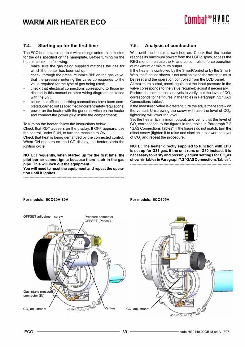
39 code HG0140.00GB-M ed.A-1507ECO
WARM AIR HEATER ECO
Venturi
Gas intake pressure connector(IN)
OFFSET adjustment screw Pressure connector OFFSET(Pascal)
CO2 adjustment CO2 adjustment
For models: ECO20A-80A For models: ECO105A
HG0140.00_IM_035
HG0140.00_IM_036
7.4. Starting up for the first timeThe ECO heaters are supplied with settings entered and tested forthegasspecifiedonthenameplate.Beforeturningontheheater, check the following:• make sure the gas being supplied matches the gas for
which the heater has been set up;• check, through the pressure intake "IN" on the gas valve,
that the pressure entering the valve corresponds to thevalue required for the type of gas being used;
• check that electrical connections correspond to those in-dicated in this manual or other wiring diagrams enclosedwith the unit;
• checkthatefficientearthingconnectionshavebeencom-pleted,carriedoutasspecifiedbycurrentsafetyregulations;
• power on the heater with the general switch on the heaterand connect the power plug inside the compartment;
To turn on the heater, follow the instructions below:Check that RDY appears on the display. If OFF appears, use the control, under FUN, to turn the machine to ON;Check that heat is being demanded by the connected control.When ON appears on the LCD display, the heater starts the ignition cycle.-------------------------------------------------------------------------------NOTE: Frequently, when started up for the first time, the pilot burner cannot ignite because there is air in the gas pipe. This will lock out the equipment.You will need to reset the equipment and repeat the opera-tion until it ignites.----------------------------------------------------------------------------------
7.5. Analysis of combustionWait until the heater is switched on. Check that the heater reaches its maximum power: from the LCD display, access the REG menu, then use the Hi and Lo controls to force operation at maximum or minimum output.If the heater is controlled by the SmartControl or by the Smart-Web, the function shown is not available and the switches must be reset and the operation controlled from the LCD panel.At maximum output, check again that the input pressure in the valve corresponds to the value required; adjust if necessary.Perform the combustion analysis to verify that the level of CO2 correspondstothefiguresinthetablesinParagraph7.2"GASConnections tables".If the measured value is different, turn the adjustment screw on the venturi. Unscrewing the screw will raise the level of CO2, tightening will lower the level.Set the heater to minimum output, and verify that the level of CO2correspondstothefiguresinthetablesinParagraph7.2"GASConnectionsTables".Ifthefiguresdonotmatch,turntheoffset screw (tighten it to raise and slacken it to lower the level of CO2 and repeat the procedure.----------------------------------------------------------------------------------NOTE: The heater directly supplied to function with LPG is set up for G31 gas. If the unit runs on G30 instead, it is necessary to verify and possibly adjust settings for CO2 as shown in tables in Paragraph 7.2 "GAS Connections Tables".----------------------------------------------------------------------------------
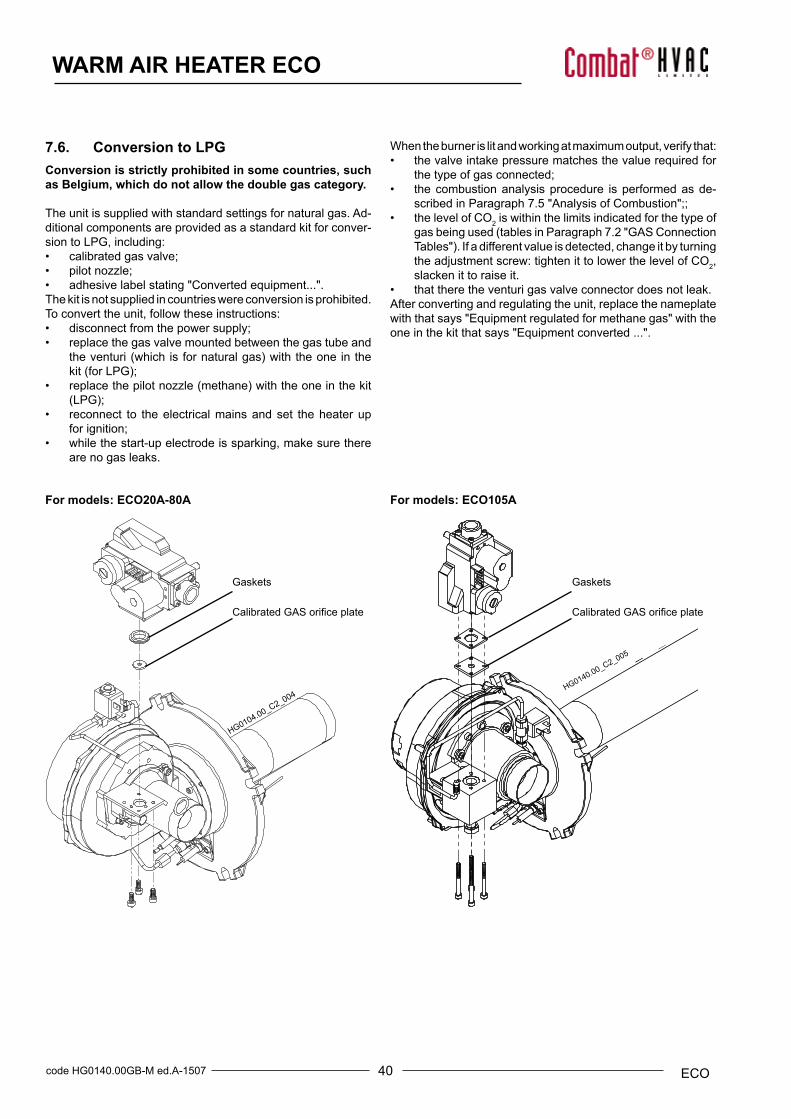
40code HG0140.00GB-M ed.A-1507 ECO
WARM AIR HEATER ECO
HG010
4.00_C
2_004
CalibratedGASorificeplate
Gaskets
For models: ECO105AFor models: ECO20A-80A
HG014
0.00_C
2_005
CalibratedGASorificeplate
Gaskets
HG0140.00_C2_005
7.6. Conversion to LPGConversion is strictly prohibited in some countries, such as Belgium, which do not allow the double gas category.
The unit is supplied with standard settings for natural gas. Ad-ditional components are provided as a standard kit for conver-sion to LPG, including:• calibrated gas valve;• pilot nozzle;• adhesive label stating "Converted equipment...".The kit is not supplied in countries were conversion is prohibited.To convert the unit, follow these instructions:• disconnect from the power supply;• replace the gas valve mounted between the gas tube and
theventuri(which isfornaturalgas)withtheoneinthekit(forLPG);
• replacethepilotnozzle(methane)withtheoneinthekit(LPG);
• reconnect to the electrical mains and set the heater upfor ignition;
• while the start-up electrode is sparking, make sure thereare no gas leaks.
When the burner is lit and working at maximum output, verify that:• the valve intake pressure matches the value required for
the type of gas connected;• the combustion analysis procedure is performed as de-
scribed in Paragraph 7.5 "Analysis of Combustion";;• the level of CO2 is within the limits indicated for the type of
gas being used (tables in Paragraph 7.2 "GAS Connection Tables").Ifadifferentvalueisdetected,changeitbyturningthe adjustment screw: tighten it to lower the level of CO2,slacken it to raise it.
• that there the venturi gas valve connector does not leak.After converting and regulating the unit, replace the nameplatewith that says "Equipment regulated for methane gas" with theone in the kit that says "Equipment converted ...".
41 code HG0140.00GB-M ed.A-1507ECO
WARM AIR HEATER ECO
HG014
0.00_C
2_006
Airorificeplate
HG0140.00_C2_006
7.7. Conversion to gas G25 - G25.1Conversion for gases from G20 to G25 is allowed only in countries of category II2ELL3B/P [Germany] and category II2HS3B/P [Hungary].For II2L3B/P countries [Netherlands] the unit is supplied and already set up for G25.For category 2E countries, where conversion from G20 to G25 is not permitted [France, Belgium and Luxembourg], the unit is supplied set up to function with either G20 or G25 without the need to be converted.Conversion from one type of gas to another can only be per-formed by authorised service centres.Conversion to G25 and/or G25.1, where possible, consists in:• for all models: pilot nozzle replacement.• fittingtheorificeplate(allowedonlyforGermany,Netherlands
andHungary;itisprohibitedinothercountries).After the conversion, relight the burner and:• check that the intake pressure to the gas valve corresponds
to the level required for the type of gas [see tables inParagraph 7.2 "GAS Connection Tables"];
• check that the level of CO2, at maximum and minimumheat output, is between the values indicated for the typeof gas. If the value is different, change it by turning theadjustment screw on the venturi: tighten it to decrease thevalue, slacken it to raise the value.
Stick the label "Equipment converted for gas G25...." in place of the one stating "Equipment set up for ......".-----------------------------------------------------------------------------------NOTE: Always pay close attention to the level of CO2 in G25.1; for G25.1 minimum and maximum heat output in the ECO105A model will always be lower than when used with G20.--------------------------------------------------------------------------------------------------------------------------------------------------------------------NOTE: The conversion kit is supplied on request----------------------------------------------------------------------------------
7.8. Conversion to gas G2.350Conversion is allowed only for Poland.Conversion from one type of gas to another can only be per-formed by authorised service centres.Conversion to G2.350 involves:• for all models: replacement of pilot nozzle.• only for models ECO65A and ECO80A: mounting a
calibratedbutterflyvalveon theair intakeof theventuri[see tables in Paragraph 7.2 "GAS Connection Tables"].
After the conversion, relight the burner and:• check that the intake pressure to the gas valve corresponds
to the level required for the type of gas [see tables inParagraph 7.2 "GAS Connection Tables"];
• check that the level of CO2, at maximum and minimumheat output, is between the values indicated for the typeof gas. If the value is different, change it by turning theadjustment screw on the venturi: tighten it to decrease thevalue, slacken it to raise the value.
Stick the nameplate "Equipment converted for gas G2.350...." in place of the one that says "Equipment set up for ......".----------------------------------------------------------------------------------NOTE: The minimum and maximum heat outputs of models ECO65A, ECO80A will be lower compared to their opera-tion with G20. The models ECO105A are not suitable for operation with gas G2.350.--------------------------------------------------------------------------------------------------------------------------------------------------------------------NOTE: The conversion kit is supplied on request----------------------------------------------------------------------------------
42code HG0140.00GB-M ed.A-1507 ECO
WARM AIR HEATER ECO
Switch for Smart Control
1 2 3 4 5 6 7 8
HG0130.00 A 005
Bracketwiththeindicationoftheposition(A,B,C,etc.)ofSTBandNTC
7.9. Replacing the gas valveIf the gas valve must be replaced, it is required to proceed with an inspection and possibly calibrate the CO2 level through the adjustments on the venturi.It is advisable to not calibrate the offset: the manufacturer is responsible for calibrating the valve.If necessary, carry out the combustion analysis procedure as described in Paragraph 7.5 "Analysis of combustion"..It is recommended to always carry out the flue gas analysis after replacing the gas valve.
7.10. Replacing STB and NTCIf STB thermostat or NCT probe need to be replaced, the posi-tion showed in table below and on the bracket installed on the heater have to be followed.
MODEL POSITION
ECO20A AECO34A BECO45A CECO65A DECO80A EECO105A F
7.11. Replacing the modulation PCBWhen replacing the PCB, it is required to carry out a few checks and set a few parameters through the LCD command or Smart Control. Every ECO heater has a list of pre-programmed default values. It is advisable to update the list at every change performed on site in order to be able to reprogram a spare PCB if needed.
Verify the hardware configuration of the PCBModify the address of the PCB with the switches, copying the exactconfigurationofthePCBthatwasjustreplaced.
Programming the parametersThe parameters that must be programmed are the following:• d0, d1, and d5 - to identify the type of equipment;• b1,b2,b3-regulatethemotorrevolutionsofthefluefan;• S1 - enables the NTC1 hot air intake probe;• ST1 is the set point value for NTC1;• H51,H52andH53-toregulatethe0/10Vdc(ifprovided);• S2, ST2 and P2 - to heat the electrical compartment (if
provided).
Programming the parameters - Operating mode ParameterscanbemodifiedfromtheLCDdisplayonthema-chine or, alternatively, from the Smart Control.
The Smart Control can be used to access all parameters [see tables on previous pages]; parameters have passwords, which are issued by the Combat Technical Service Depart.Please refer to the Smart Control manual for instructions for the procedureforaccessandmodificationoffunctionalparameters.Please remember that all changes to parameters must be done ONLYwiththeburnerOFF(withdisplayshowingrdyoroff).

43 code HG0140.00GB-M ed.A-1507ECO
WARM AIR HEATER ECO
HG
0130
.00
A 01
4
Verify that the start-up electrode discharges on the external edge of the pilot burner.
Keep the detection elec-trode at a tangent to the pilot burner.
8. MAINTENANCETokeepthemachineefficientandguaranteealonglifetimeofthe heater, it is advisable to run some inspections every year, before turning it on for the season:1) checkthestatusofthestart-upelectrodes,detectionelec-trodesandpilotflame;2) check thestatusofflueexhaustandair intakeductsandterminals;3) checkthestatusoftheventuri;4) checkandcleantheexchangerandburner;5) checkandcleanthewatertrap6) checktheintakepressureatthegasvalve;7) checkthefunctionoftheflamemonitoringequipment;8) checkthesafetythermostat(s);9) checktheionizationcurrent.----------------------------------------------------------------------------------NOTE: Operations at points 1, 2, 3, 4 and 5 must be per-formed after disconnecting the heater from the electricalmains and closed the gas supply. Operations at point 6, 7,8 and 9 must be done with the heater on.-----------------------------------------------------------------------------------
1) Inspection of electrodesDismantlethecompletepilotflameanduseajetofcompressedair to clean the mesh and nozzle. Check the integrity of theceramic and use sandpaper to remove any oxidation on themetal parts of the electrodes. Check the correct position of theelectrodes(seedrawingbelow).It is important that the detec-tion electrode is at a tangent to the head of the pilot and notinside it. The start-up electrode must discharge onto the meshof the pilot burner.
2) Inspection of flue exhaust and air intake ducts Visuallyinspectwherepossibleorexaminewithspecifictools tocheck the condition of the ducts.Remove dust that forms on the air intake terminal.
3) Inspection and cleaning the venturiRemove any dirt at the mouth of the venturi with a brush, andbe careful to not let it fall inside the venturi.
4) Inspection and cleaning of the exchanger and burnerPerfect combustion in ECO heaters prevents soot forming,which is normally caused by bad combustion. It is advisable,therefore, to not clean the exchanger and burner unless thereare exceptional circumstances.An accumulation of soot inside the exchanger could be revealed by a sizeable variation in the heat output that is caused byimproper functioning of the gas valve.Should it become required to clean the burner and/or exchanger, all of the gaskets mounted between the burner and the exchanger must be replaced.
5) Inspection and cleaning of the condense trapClean the trap every year, and check the connections. Makesure there are no traces of metallic residue. If metallic residuehas formed, increase the number of inspections.
6) Inspection of intake gas pressureVerify that the intake pressure at the valve corresponds to thevalue required for the type of gas connected.Thisverificationmustbedonewiththeheateronatthemaxi-mum heat output.
7) Inspection of flame monitoring equipmentWith the heater operating, close the gas tap and verify that themachine faults, signaled on the LCD display on the CPU PCBon the machine with code F10. Reopen the gas tap, reset thefault and wait for the heater to start back up.
8) Inspection of the safety thermostat(s);This procedure must be done with the heater on and the burner lit.Open the thermostat series with an insulated tool [230 V], remove the fast-on from the safety thermostat, wait for the F20 blocksignal to appear on the LCD display on the CPU PCB on themachine. Re-close the thermostat series, then reset the fault.
9) Inspection of the ionization currentThis procedure can be done directly from the LCD display byentering into the I/O menu. The IOn parameter indicates thevalue of the ionization current, and the reading is as follows:• 100, indicates that the value is more than 2 microAmperes,
which is plenty for the equipment to function;• from 0 to 100, indicates a value from 0 to 2 microAmperes;
for example, 35 corresponds to 0.7 microAmperes, whichistheminimumthresholddetectablefortheflamemonitor-ing equipment.
The value of the ionisation current must not be below 2 micro-Amperes. Lower values indicate: the detection electrode in a bad position, a rusted electrode or one about to stop functioning.
44code HG0140.00GB-M ed.A-1507 ECO
WARM AIR HEATER ECO
Bur
ner f
anR
emot
e re
set
R
emot
e O
N/O
FF
CP
U S
MA
RT
PC
B G
1680
0.01
TER
Equ
ipm
ent P
CB
G10
900
CA
BLE
CO
LOU
R C
OD
ING
WT
whi
teO
R
oran
geR
D
red
PK
pi
nkB
L bl
ueG
R
gree
nY
G
yello
w-g
reen
BW
br
own
GY
grey
BK
bl
ack
YL
yello
w
FAN
SE
1 Fo
r, E
CO
20A
, EC
O34
A, E
CO
45A
.E
2 E
CO
65A
, EC
O80
A.
E3
For E
CO
105A
.
KE
Y
TS
safe
ty th
erm
osta
tEV1
firstGASsolenoidvalve
EV
2 m
ain
GA
S s
olen
oid
valv
eE
VP
pilo
t GA
S v
alve
IONO
flamedetectionelectrode
AC
C
star
t-up
elec
trode
TER
flamemonitoringequipm
ent
V AG
bu
rner
fan
NTC
1 te
mpe
ratu
re p
robe
KO
ND
co
nden
satio
n de
tect
ion
elec
trode
9. WIRING DIAGRAM
Wiring diagram ECO20A/ECO105A (codeJG0350.00)

45 code HG0140.00GB-M ed.A-1507ECO
WARM AIR HEATER ECO
CPU PCB caseG16881 BaseG16882 Cover
HG0161.00 002
Connector Burner Fan ModulationG10054
ON/OFF ConnectorG10051
ALARM ConnectorG10052
ModBus ConnectorG10054
NTC1 ConnectorG04763
0-10Vdc ConnectorG10052Power supply connector Burner fanG10053
Electrical Power Supply 230 Vac ConnectorG10180
TER equipment PCBG10900
CPU-SMART PCBG16800.01
CPU-SMART Display cableG16791
S. T. terminalG10161
HG0130.00 A 007
10. LIST OF SPARE PARTS
10.1. Parts for the electrical panel

46code HG0140.00GB-M ed.A-1507 ECO
WARM AIR HEATER ECO
HG0140.00_IM_019
HG0131.00 A 009_A
Detection electrodeG16334.01
Start-up electrodeG16333.01
PilotflameunitG28030 for all gas categories.G28030-0001 LPG
BurnerflangegasketG16332
Burner torch gasketG14086 ECO20A-80AG14450 ECO105A
Burner ventilator gasketG14086
Air/gas ventilatorG22903 ECO20A-
34AG22904 ECO45A-
65AG22815 ECO80AG22816 ECO105A
Venturi gas valveG14898 ECO20AG14990 ECO34AG16219 ECO45AG14154 ECO65A-80AG14154.08 ECO105A
Gas valveG14067 ECO20A-80AG14456 ECO105A
Burner torchG14534-P ECO20A-
34AG14375.01-P ECO45AG16340.01-P ECO65AG14370.01-P ECO80AG14269.05-P ECO105A
Butterflygasket2x X01133 For all models
Pilot solenoid valveG14378 For all models
Pilot gasketG16331
10.2. Parts for the burner unit
Flame detection cableG27511
RVK cable condensation detectionG28303
Start-up cableG14062.01
HG0130.00 A 010
47 code HG0140.00GB-M ed.A-1507ECO
WARM AIR HEATER ECO
HG0140.00_IM_014
HG0140.00_IM_013
HG0140.00_IM_011
Fan G07660 no.1 ECO20AG03270 no.2 ECO65A
no.3 ECO105AG04990 no.1 ECO34A-45A
no.2 ECO80A
Power supply socketG12063
Power supply plugG12064.01
Condense trap complete with condensation detection electrode G27810 For all models
Tabs G27582 no.7 ECO20AG27583 no.7 ECO34A
no.8 ECO45Ano.18 ECO105A
G27585 no.8 ECO65AG27586 no.18 ECO80A
NTC1 probeG16400 For all models
Safety thermostatG16300 For all models
Condensation detection electrodeG27806 For all models
Cover X04511 For all models
HingesX01485 For all models
LCD control case G16795 For all models
Display PCBG16790For all models
condense trap pipeG27576 For all models
48code HG0140.00GB-M ed.A-1507 ECO
WARM AIR HEATER ECO
Combat HVAC Limited Unit A, Kings Hill Business ParkDarlaston Road, WednesburyWest Midlands, WS10 7SH UKTelephone: 0121 506 7700Fax: 0121 506 7701
Service Telephone: 0121 506 7709Service Fax: 0121 506 7702E-mail: [email protected]: [email protected]