gaze tracking using a regular web camera · gaze tracking using a regular web camera submitted in...
TRANSCRIPT

Gaze Tracking Using A Regular Web
Camera
Submitted in partial fulfilment
of the requirements of the degree of
Bachelor of Science (Honours)
of Rhodes University
David Jonathan Wild
Grahamstown, South Africa
November 2012

Abstract
Traditional gaze tracking systems rely on either contact and invasive hardware, or ex-
pensive and non-standard hardware. To address this problem research has been done
into systems that use only simple hardware to create gaze tracking systems. This system
attempts to prove that is is possible to create a gaze tracking system using a regular web
camera and the free, open source Computer Vision library OpenCV. This is achieved by
researching various techniques required for such a system and then measuring the perfor-
mance of the created system. Analysis of the results concluded that while the error of the
system was greater than desired, in conjunction with the research done in this field, it is
possible to create a robust system using simple hardware.

Acknowledgements
I would like to thank my supervisor, James Connan, for assisting me in this project, my
family and friends who helped me through the rough patches, and the Rhodes University
Computer Science Department for their support and the opportunity to complete this
degree.
I would like to acknowledge the financial and technical support of Telkom, Tellabs,
Stortech, Genband, Easttel, Bright Ideas 39 and THRIP through the Telkom Centre
of Excellence in the Department of Computer Science at Rhodes University.

ACM Computing Classification System Classification
Thesis classification under the ACM Computing Classification System (1998 version, valid
through 2012)
I.5.2 [Design Methodology ]: Feature Evaluation and Selection
I.5.4 [Applications ]: Computer Vision
I.5.5 [Implementation]: Interactive Systems
K.4.2 [Social Issues ]: Assistive technologies for persons with disabilities
General Terms: Gaze Tracking, Feature detection, Eye Movement, Computer Vision

Contents
1 Introduction 1
1.1 Is Gaze Tracking Useful? . . . . . . . . . . . . . . . . . . . . . . . . . . . . 2
1.2 Problem Statement and Research Goals . . . . . . . . . . . . . . . . . . . . 3
1.3 Structure of Thesis . . . . . . . . . . . . . . . . . . . . . . . . . . . . . . . 3
2 Background Literature 4
2.1 Introduction . . . . . . . . . . . . . . . . . . . . . . . . . . . . . . . . . . . 4
2.2 Human Eye . . . . . . . . . . . . . . . . . . . . . . . . . . . . . . . . . . . 4
2.2.1 Eye Structure . . . . . . . . . . . . . . . . . . . . . . . . . . . . . . 5
2.2.2 Eye Movements . . . . . . . . . . . . . . . . . . . . . . . . . . . . . 6
2.3 Methods of finding the Eye . . . . . . . . . . . . . . . . . . . . . . . . . . . 8
2.3.1 Haar Classifiers . . . . . . . . . . . . . . . . . . . . . . . . . . . . . 8
2.3.2 Infrared Reflection . . . . . . . . . . . . . . . . . . . . . . . . . . . 10
2.4 Algorithms . . . . . . . . . . . . . . . . . . . . . . . . . . . . . . . . . . . . 11
2.4.1 Real-time gaze Tracking Algorithm with head movement Compen-
sation (RTAC) . . . . . . . . . . . . . . . . . . . . . . . . . . . . . 11
i

CONTENTS ii
2.4.2 Neural Networks (NN) . . . . . . . . . . . . . . . . . . . . . . . . . 12
2.5 Summary . . . . . . . . . . . . . . . . . . . . . . . . . . . . . . . . . . . . 13
3 Design 15
3.1 Design Decisions . . . . . . . . . . . . . . . . . . . . . . . . . . . . . . . . 15
3.2 Web Camera . . . . . . . . . . . . . . . . . . . . . . . . . . . . . . . . . . 16
3.3 Programming Language . . . . . . . . . . . . . . . . . . . . . . . . . . . . 16
3.4 General Algorithm . . . . . . . . . . . . . . . . . . . . . . . . . . . . . . . 17
3.4.1 Loop steps . . . . . . . . . . . . . . . . . . . . . . . . . . . . . . . . 17
3.4.2 Main Program . . . . . . . . . . . . . . . . . . . . . . . . . . . . . . 18
3.5 Summary . . . . . . . . . . . . . . . . . . . . . . . . . . . . . . . . . . . . 20
4 Implementation 21
4.1 Introduction . . . . . . . . . . . . . . . . . . . . . . . . . . . . . . . . . . . 21
4.2 Facial Detection . . . . . . . . . . . . . . . . . . . . . . . . . . . . . . . . . 21
4.3 Eye Detection . . . . . . . . . . . . . . . . . . . . . . . . . . . . . . . . . . 23
4.4 Pupil Detection . . . . . . . . . . . . . . . . . . . . . . . . . . . . . . . . . 24
4.5 Corner Detection . . . . . . . . . . . . . . . . . . . . . . . . . . . . . . . . 25
4.6 Calibration . . . . . . . . . . . . . . . . . . . . . . . . . . . . . . . . . . . 26
4.7 Main Program design . . . . . . . . . . . . . . . . . . . . . . . . . . . . . . 27
4.8 Transforming to Window Coordinates . . . . . . . . . . . . . . . . . . . . . 28
4.9 Summary . . . . . . . . . . . . . . . . . . . . . . . . . . . . . . . . . . . . 29

CONTENTS iii
5 Results 30
5.1 Testing . . . . . . . . . . . . . . . . . . . . . . . . . . . . . . . . . . . . . . 30
5.1.1 Results . . . . . . . . . . . . . . . . . . . . . . . . . . . . . . . . . . 30
5.1.2 Discussion . . . . . . . . . . . . . . . . . . . . . . . . . . . . . . . . 32
5.2 Known Limitations . . . . . . . . . . . . . . . . . . . . . . . . . . . . . . . 33
5.2.1 Design Choices . . . . . . . . . . . . . . . . . . . . . . . . . . . . . 33
5.2.2 Implementation Choices . . . . . . . . . . . . . . . . . . . . . . . . 34
5.3 Summary . . . . . . . . . . . . . . . . . . . . . . . . . . . . . . . . . . . . 34
6 Conclusion 35
6.1 Effectiveness of the System . . . . . . . . . . . . . . . . . . . . . . . . . . . 35
6.2 Future Work . . . . . . . . . . . . . . . . . . . . . . . . . . . . . . . . . . . 36
Bibliography 37
A Full Table of results 41
B Installing OpenCV 44
B.1 Installing in Windows . . . . . . . . . . . . . . . . . . . . . . . . . . . . . . 44
B.2 Linking your Visual Studio Project . . . . . . . . . . . . . . . . . . . . . . 45
C Code Listings 47
C.1 Face Detection . . . . . . . . . . . . . . . . . . . . . . . . . . . . . . . . . 47
C.2 Eyes Detection . . . . . . . . . . . . . . . . . . . . . . . . . . . . . . . . . 49

CONTENTS iv
C.3 Finding Center of the pupil . . . . . . . . . . . . . . . . . . . . . . . . . . 51
C.4 Finding the Corner . . . . . . . . . . . . . . . . . . . . . . . . . . . . . . . 52

List of Figures
2.1 Image of the Eye: Taken from http://www.vision-training.com/en/
Eye%20Anatomy/Eye%20anatomy.html . . . . . . . . . . . . . . . . . . . . 6
2.2 Example of Haar features: Taken from [27] . . . . . . . . . . . . . . . . . . 9
3.1 Gaze Loop Steps: Logical Design . . . . . . . . . . . . . . . . . . . . . . . 17
4.1 Face detection Image . . . . . . . . . . . . . . . . . . . . . . . . . . . . . . 22
4.2 Eye detection Image . . . . . . . . . . . . . . . . . . . . . . . . . . . . . . 23
4.3 Left side of Face ROI . . . . . . . . . . . . . . . . . . . . . . . . . . . . . . 24
4.4 Right side of Face ROI . . . . . . . . . . . . . . . . . . . . . . . . . . . . . 24
4.5 Image after Equalisation . . . . . . . . . . . . . . . . . . . . . . . . . . . . 24
4.6 Image after Thresholding . . . . . . . . . . . . . . . . . . . . . . . . . . . . 25
4.7 Pupil Detected . . . . . . . . . . . . . . . . . . . . . . . . . . . . . . . . . 25
4.8 ROI of Corner Search . . . . . . . . . . . . . . . . . . . . . . . . . . . . . . 26
4.9 the Discovered Corner . . . . . . . . . . . . . . . . . . . . . . . . . . . . . 26
4.10 5 Dots into Calibration . . . . . . . . . . . . . . . . . . . . . . . . . . . . . 27
v

LIST OF FIGURES vi
4.11 Diagram of Distance Ratio’s . . . . . . . . . . . . . . . . . . . . . . . . . . 29
5.1 Sample Console Output . . . . . . . . . . . . . . . . . . . . . . . . . . . . 31

List of Tables
5.1 Table of results for point in Region 1 . . . . . . . . . . . . . . . . . . . . . 31
A.1 First Table of results for points . . . . . . . . . . . . . . . . . . . . . . . . 41
A.2 Second Table of results for points . . . . . . . . . . . . . . . . . . . . . . . 42
A.3 Third Table of results for points . . . . . . . . . . . . . . . . . . . . . . . . 43
vii

Chapter 1
Introduction
In his paper on non-invasive eye tracking technologies, Gao stated that gaze tracking
technology is still in the “embryonic stages” [6] of development and is not ready to be
used in daily life. Despite this statement there are already various systems, like the
Starburst system put forward in [16], and the Tobii system1 mentioned in [5]. Though
systems like these are available, we are yet to see a widespread usage of them because,
as mentioned previously, the field is still in it’s embryonic stages and is yet to become an
adopted technological advance.
A possible reason for this lack of integration into commercial society is that many of the
previous systems proposed, like the system in [15], require head mounted or invasive gear.
This creates the need to research into non-contact systems, such as the system put forward
in [8], which can perform at the same efficiency level. However, previous systems, like the
system designed in [19], required the use of a large fixed infrared camera, an LED array
as well as eye positioning cameras mounted on top of the screen to function efficiently.
This need for extra equipment is still a problem for regular users since they do not wish
to purchase additional hardware.
In an ideal scenario, the user would only need to install the software and buy some readily
available hardware to interface with their computer.
1The website for the system is http://www.tobii.com/pceye
1

1.1. IS GAZE TRACKING USEFUL? 2
1.1 Is Gaze Tracking Useful?
So it is apparent that gaze tracking requires further development, but is it worth develop-
ing these tools? This section gives some examples of application and research done with
similar systems to show the benefits of gaze tracking.
Gaze tracking has a large number of possible applications that benefit society. There are
many obvious benefits, such as aiding the disabled 2 or a new form of human computer
interaction. The interesting applications are more obscure and usually involve helping
researchers to see through their subject’s eyes.
In his paper from 1996, Tock attempted to track and measure a motor vehicle driver’s
eyes for eyelid separation. This was to aid in a larger system that could detect when
a driver was getting drowsy, which could reduce the number of road accidents due to
fatigue, potentially saving lives. [25]
In [2], gaze tracking was used to study the user’s visual behaviour when surfing the
Internet. The applications of this research affect advertising, website design, improving
usability in computer systems and optimising web browsers and websites for maximum
user experience.
An even more interesting study was presented in [21] where the researcher investigated
the behaviour of the eyes while reading a book and from that information was able to
infer information on how cognitive and lexical processing affects reading and learning.
This could lead to the development of cognitive development theories that aid in teaching
and learning through reading.
From these examples, it is apparent that gaze tracking could have a beneficial role in
society, and that it is worth researching into this field.
2As presented in [17]

1.2. PROBLEM STATEMENT AND RESEARCH GOALS 3
1.2 Problem Statement and Research Goals
This research project investigates the ability to create a gaze system that functions using
cheap hardware but efficiently enough to be useful. Since a large number of computer
users already have web cameras and they are relatively cheap to buy, the hardware used
in this system will be a regular web camera.
The final goal of this project is to ascertain whether it is possible to create a Gaze tracking
system using a regular web camera. The system will use the open source library Open
Computer Vision (OpenCV) to implement the techniques. Simple techniques that are
supported by OpenCV will implemented as a baseline comparison.
1.3 Structure of Thesis
The remaining chapters of this thesis are described below:
• Chapter 2 describes the background required to understand the proposed system
and some examples of other systems
• Chapter 3 gives an overview of the system design and describes certain decisions
made when designing the system
• Chapter 4 provides a step by step implementation of the system, providing the
OpenCV methods and describing the system structure
• Chapter 5 describes and discusses the results obtained from the system
• Chapter 6 outlines the conclusions drawn from this research and identifies possible
extensions of this project

Chapter 2
Background Literature
2.1 Introduction
Gaze tracking, as the name suggest, is tracking the gaze of a person. Thus, the objective
of a gaze tracking system is to track the focus of the user’s vision. So it is necessary
to be able to track the eye, and possibly other features, in an image. For this objective
more information on the relevant biology and behavior of the eye is required. To this end,
this chapter will present some background knowledge required for the creation of a gaze
tracking system, give some example algorithms already in use, and will describe some
techniques used within the proposed system.
2.2 Human Eye
Understanding the workings of the eye is paramount to any sort of eye or gaze tracking
system. In order to understand how to find the focus point of the gaze it is necessary
to first understand the relevant biology of the eye and what eye behaviour is relevant to
finding the focus point.
4

2.2. HUMAN EYE 5
2.2.1 Eye Structure
The important factor to consider when looking at the structure of the eye is where the
receptors of the eye are. As stated in [12], it would be a problem if there was a uniform
spread of receptors over the eye but instead there are higher density and lower density
areas. One such area is the fovea. As shown in figure 2.1, the fovea is a spot on the back
of the eye. According to [12, p3], the fovea covers a one degree width with the vertex of
the eye. This implies that the further away from the eye we get the larger the area of
uncertainty on the screen is. Outside of the fovea the clearness of person’s vision drops
to half or less that of the fovea and in [12] it was found that peripheral vision is not good
enough to focus or read text with. Considering that we wish to find the focus point of the
vision, the fovea then becomes the area to consider in our applications. It is mentioned
in [20] that to focus on an object a person will move their eyes such that the focus area is
within the fovea area. A problem with considering the fovea, as discussed in [12], is that
within the fovea there is still the one degree of error. If the focus area is sufficiently small
enough, then the focus point could shift without any eye movements since the focus point
would still be within the fovea‘s one degree of vision. The consequence of this is that it
is unlikely to get less than one degree of error when measuring using eye position. This
is consistent with the errors in [1], [8], [18], [23] and [28].
Another problem is that the fovea is within the eye socket and extremely small, as can
be seen by figure 2.1. This makes using it as a feature for tracking difficult. Instead the
pupil or Iris of the eye is tracked and the focus point inferred from that. This is possible
because the object of focus is kept in the centre of the eye so it is possible to find the
focus point by looking at the outer layers of the eye and inferring the fovea’s focus point
from those results. The area of interest thus become the Pupil or the Iris, as stated above.
[20].

2.2. HUMAN EYE 6
Figure 2.1: Image of the Eye: Taken from http://www.vision-training.com/en/Eye%
20Anatomy/Eye%20anatomy.html
2.2.2 Eye Movements
Regular human interfacing with a computer using a mouse is smooth. The mouse moves
smoothly across the working area while the user is moving it. We perceive the same of
our vision. In [11], [12] and [20], eye movements are described as a series of sudden jumps
with rest points in between. The jumps are called Saccades and the rests in between are
named Fixations [20].
Saccades
As stated above, saccades are extremely quick jumps between focus points. In [14], a paper
on Saccadic Suppression, it was found that “transsaccadic spatial memory is sacrificed in
order to maintain perceptual stability” [14]. This means that during the saccadic motion
no visual information is gained in order to maintain the perception of smoothness and
stability. This effect is known as saccadic suppression [20]. So to gain information into

2.2. HUMAN EYE 7
the focus points, it is not necessary to look into the saccades but rather the fixations
become the more valuable source of information.
It is noted in [20] that these quick movements need to be distinguished from three other
eye movements, referred to as Saccadic Eye Movements (SACs) in [7]. These movements
are pursuit, vergence and vestibular. Pursuit eye movements follow a moving focus point,
performing saccades to catch up if the point is moving too rapidly, but the general eye
movement is notably slower than that of a saccades. Vergence eye movements are when the
eyes move inward to focus on a point that is nearby. Vestibular movements are rotations
of the eye to compensate for larger head or body movements. These three movements are
less important than saccades for information processing and as such for Gaze Tracking.
[20]
Fixations
The rests in between saccades, where the eye is focusing and gaining visual information,
are called fixations. Jacob describes fixations as “a period of relative stability during
which an object can be viewed” [12, p5]. The reason for the term relatively in the above
statement is because there are still tiny movements during the fixations. These movements
are named smooth pursuit eye movements (SPEMs) in [7]. [12, p5]
There are three different types of these small movements and they are usually “within a
one-degree radius” [12, p5] which agrees with the previously mentioned fovea error. The
first is a constant tremor of the eye called a nystagmus. The second movement is known
as drift, which is where the eye occasionally drifts slightly off the focus point due to a
“less-than-perfect control of the oculomotor system by the nervous system” [20, p374].
These drifts are then compensated for by micro-saccades which are an even more rapid
eye movement then saccades, that brings the focus of the eye back to the object. [20]
As mentioned above we need only look at the fixations to find the focus of the eye. This
is good since the fixations last longer than the saccades. [20]

2.3. METHODS OF FINDING THE EYE 8
2.3 Methods of finding the Eye
The most precise methods for finding the eye accurately involve invasive or expensive
equipment. A method is mentioned in [12] that uses a contact lens that is fixed in place
on the eye. This reduces the problem to tracking something attached to the lens. The
problem with this method is that, while it is accurate, it is invasive and uncomfortable to
use. This makes it highly impractical as a solution to the problem. The aim of much of the
research into this field currently is to create an easily accessible and user sensitive device
that is not intrusive and could become commercially viable as a method of computer
interfacing that exceeds that of a mouse and potentially the keyboard too. Therefore the
ideal is to use non-contact and non-invasive techniques for Gaze and Eye Tracking. Of
course this introduces a new set of problems specific to these techniques, such as head
movements, which are considered in Chapter 3. This section will explain several relevant
techniques for finding the Eye. [12]
2.3.1 Haar Classifiers
Haar classifier objects are based on a compilation of Haar-like features. These features use
the changes in contrast values between adjacent rectangles of pixels to determine relative
light and dark areas. Two or three rectangles with relative contrast differences form a
single Haar-like feature. The features, as shown in figure 2.2 below, are then used to detect
objects in an image. These features can be scaled up and down easily by increasing or
decreasing the size of the pixel group. This allows Haar-like features to detect objects of
various sizes with relative ease. [27]

2.3. METHODS OF FINDING THE EYE 9
Figure 2.2: Example of Haar features: Taken from [27]
The rectangles themselves are calculated using an intermediate image called the integral
image. This integral image contains the sum of the intensities of all the pixels to the left
and above the current pixel. The equation for this is shown below. [27]
AI[x, y] =∑x′≤xy′≤y
A(x′, y′)
However, the rotated features, as seen in 2.2, create a different integral image called a
rotated integral image based off the equation below instead. [27]
AR[x, y] =∑x′≤x
x′≤(x−|y−y′|)
A(x′, y′)
Using the integral image, or rotated integral image as needed, and taking the difference
between two or three connected rectangles it is possible to create a feature of any scale. A
benefit of Haar-like features is that calculating features of various sizes requires the same
effort as two or three pixels. This makes Haar features fast and efficient to use as well.
[27]
A requirement to create classifiers for specific objects is to train the classifiers using a set
of positive samples containing the image to be detected and a negative set not containing

2.3. METHODS OF FINDING THE EYE 10
the image. Once trained, the classifiers can be used to detect the objects. [27]
Some of the more popular uses of Haar Cascades are Eye and Face detection.
2.3.2 Infrared Reflection
The usefulness of using infrared light sources is that they enhance the contrast between
the pupil and the iris [26]. The following is an example of how to use the infrared
reflection to detect the eyes.
In [6], the authors firstly define a 60X60 pixel region (reduced from a 1280X1024 pixel
region) centered on a rough estimate of the centre of the pupil. Since different parts of
the eye have different refractive indexes to infrared light the pupil appears black and the
rest of the eye is not. Using a simple threshold algorithm to process a grey scale filtered
version of the image received from the camera, they can check for all points below the
threshold to find the ROI. The threshold equation used in [6] is given below. [6, p3609]
xpupil =1
N
N∑n=1
xn
ypupil =1
N
N∑n=1
yn
Similarly, an infrared camera was used in [13] in conjunction with a threshold algorithm
to determine the pupil location.
The general idea of using infrared is that the reflection of the infrared light simplifies the
process of pinpointing the centre of the pupil. This shortens a potentially time consuming
task and can increase the accuracy of the pupil detection, improving the efficiency of an
eye tracking system. The negative side of this is that the need for an infrared light makes
the product slightly harder to distribute. There could also be other light sources, or
shadows that disrupt this image and create “noise” [6] making it harder to calculate the
focus point, but this is a problem for most non-obtrusive systems.

2.4. ALGORITHMS 11
2.4 Algorithms
A Gaze tracking system is a combination of several different techniques, of which Eye
tracking is only a part. There are a great many methods of combining these techniques
to create algorithms. Some examples of Algorithms are given below in order to show the
differences, similarities and general structure of gaze tracking algorithms.
2.4.1 Real-time gaze Tracking Algorithm with head movement
Compensation (RTAC)
The explanation of RTAC in [8] begins by referring to the “Pupil Center Corneal Reflection
(PCCR)” [8, p395]. According to the PCCR, gaze direction calculations firstly acquire
the pupil-glint vector, and then use a gaze mapping function. The glint is the reflection of
the infrared light source in the eye. The pupil-glint vector is then the 2D vector between
the glint and the pupil. The algorithm then uses a mapping function to map this vector
to the 3D gaze direction. The mapping function is specified by the following functions:
θh = bθhVx + aθh
θv = bθvVy + aθv
Where θh is the angle between the gaze direction and the horizontal direction and likewise
θv is the angle between the gaze direction and the vertical direction. The coefficients, a
and b, are estimated using the sets of pairs of pupil-glint vectors.
The next step in this algorithm is the head movement calculation. The previous cal-
culation does not include adaption to head movements. As such, the system needs to
compensate for these head movements. This calculation is quite intricate. The basis for
it, however, is these two equations:
∆Ix = (b2x∆Lh + a2x)∆d2 + (b1x∆Lh + a1x)∆d+ (b0x∆Lh + a0x)

2.4. ALGORITHMS 12
∆Iy = (b2y∆Lv + a2y)∆d2 + (b1y∆Lv + a1y)∆d+ (b0y∆Lv + a0y)
These two equations describe the changes in head position in the horizontal and vertical
plane respectively. The derivation of these equations can be found in [8, p397]. Once the
head movement has been calculated then the system needs to compensate for this move-
ment. The compensation method employed by this algorithm uses two sets of equations:
the calculation of the proportional change in magnification and then using these values
to calculate the compensation value in the horizontal and vertical directions. [8, p397].
Then the next step is fixing the users head during calibration in order to get the initial
parameters required. After this calibration the user can move their head freely and the
parameters are compared to do the calculations.
In [8], it was found that this algorithm had an accuracy rate of approximately one degree,
and that there was little difference between different subjects. There was also little dif-
ference between different positions of the head, but the error did increase when the head
was moved near the boundaries of the camera’s vision.
2.4.2 Neural Networks (NN)
The first step of using Neural networks, according to [23], is Face and Eye detection.
The eye and face are detected using the intensities of the pixels in a region and then each
region is given a score. The scores are then arranged hierarchically and fed to an OpenCV
library for detection. [23]
The next step is to reduce the ROI to a smaller picture. This picture is usually extremely
small being less than a thousandth of the size of the original image and only containing the
eye. From there the image is processed to make a clearer input for the neural network. The
two processes applied are histogram equalisation that brightens the sclera and darkens
the boundary of the eyes, and resizing the image to a smaller format using a bicubic
interpolation. This reduces the pixel by fourfold which cuts the training time of the NN
from several minutes to a time generally less than 60 seconds. [23]

2.5. SUMMARY 13
The intensity of each pixel in the image is used as an input for the neural network. The
neural network employed a feed forward, two-layer structure. The actual Neural network
workings are dealing with Artificial Intelligence concepts rather than image processing
and as such will be left out.1 [23]
The error using the Neural Network approach in [23] was found to be approximately 1.5
degrees. The error found in [1] was the same and since the paper was published in 1994
which shows little progress in this particular algorithm, or suggests that there is an lower
limit to the error.
A Neural Network was used differently in [26]. Initially the system used blink detection
to pinpoint the location of the eyes. Once the eyes are found the Iris detection was done
using a combination of edge detection and circular Hough transforms, followed by corner
detection aimed at finding both the inner and outer corners. The Neural Network was
only used to map the relation between the eye features and the gaze direction. This is a
different approach than the one used in [23] in that the feature detection is done without
the Neural Network. [26]
Both algorithms for NN were effective but the Neural network added complexity to the
system and had to be trained which increased the calibration time.
2.5 Summary
In order to track the user’s gaze we need to know where the pupil is. By tracking the
pupil and other features we can work out where the gaze is. The system does not need
an excessively powerful camera as the fixations of the eye are the only meaningful data
required to find the gaze and these correspond to the longest time period of the eye
movement.
There are a large number of algorithms available for use, which employ an even larger
number of varying techniques. The fundamental requirements appear to be eye detection,
1More information on NN can be found in [10]

2.5. SUMMARY 14
pupil detection, detection of an additional feature, and then the transformation to the
focus coordinates. As such, this will be how this system will be designed.

Chapter 3
Design
The aim of this project is to create a Gaze tracking system using simple techniques, a
regular web camera and the Computer Vision library OpenCV. Since the logical design
of most Gaze Tracking systems is fairly standard, the overall design of this system is very
similar to existing systems. However, the tools used in these systems have a large amount
of variation in them. As such, the particular techniques used were chosen to be simple
techniques that were easily implemented as a baseline comparison.
The chapter will begin by detailing some design decisions, followed by the motivations
behind the use of the particular web camera and programming language, and finally move
onto the logical and actual design specifics.
3.1 Design Decisions
Traditional, non-contact Eye tracking systems had several problems that need to be taken
into consideration when calculating the focus point or when finding the eye. The first and
foremost of these is head movement, as mentioned by [23]. Older eye tracking systems
required the user to keep their head still in order to accurately capture the data. More
comprehensive systems, like [8], [9] and [13] , take this problem into account in their
algorithms. These algorithms all tend to incorporate infrared lighting.
15

3.2. WEB CAMERA 16
Another problem facing the field of Eye Tracking is known as the “Midas Touch Prob-
lem” [12, p15]. This problem is a direct result of the way the eye moves. People look at
a point to see if they are interested in it. So, currently, the eyes show where the user’s
interest is before the input device is brought into use. Now, if the eye is substituted as
a pointer that the mouse should follow, then the system might end up acting on com-
mands that the user did not intend. So it is necessary to be able to sort out meaningful
commands from simple observations, or non-meaningful movements. [12]
This Midas Touch Problem is solved in [22], specifically in regards to typing with eye
input, by implementing a dwell time activation. Dwell time activation is a simple concept
that reduces the likelihood of the Midas touch problem by having the eye-pointer only
interact with an object after a fixed period of time. The time in [22] was set to 403ms.
Another solution is to use blink detection as the basis for interaction commands.
This system will not deal will head movement cancellation as it is proposed as a simple
system and the technique requires an advanced implementation, as mentioned in sec-
tion 2.4.1. In order to avoid the Midas touch problem the system will not incorporate
Operating System click functionality. Therefore these two problems are avoided.
3.2 Web Camera
The web camera used for this project is the Logitech C300. It is a 1.3 megapixel web
camera. It costs R1461 in South Africa. This is a relatively cheap web camera and as
such suited the purposes of the project.
3.3 Programming Language
A natural choice to make is which programming language the system should be imple-
mented in. OpenCV supports three languages as a default: C, C++ and Python. In order
1found at http://www.pricecheck.co.za/offers/9061215/Logitech+960-000354+Webcam+C300/

3.4. GENERAL ALGORITHM 17
to minimise the time needed to create the system, C was discarded as I have minimal
experience in the language. A simple test was then run on Python to see if it was possible
to attempt to keep the system in real time but Python was found to be insufficient. C++
was the next choice to simplify the implementation of the system. This is because C++
has support in Visual Studio and has been covered in the undergraduate curriculum.
3.4 General Algorithm
The general algorithm of the system is split into two parts: the continuous loop to get
the gaze, and the main program.
3.4.1 Loop steps
The loop steps are the steps required to get all the necessary data from a single frame.
The simplest form of this design is shown below 2:
Figure 3.1: Gaze Loop Steps: Logical Design
2This step by step procedure is an adaption of design from [3]

3.4. GENERAL ALGORITHM 18
The first step is to get a single frame from the camera. Once the frame is retrieved the
face is detected. Face detection is done first in order to reduce the possible false positives
from the eye detection. Facial detection does this by reducing the search area to only this
facial area. A requirement of this is that the face detection needs to be a quick process in
order to not add extra delay to the system. The next step is the eye detection. This step
takes the area the face was found in and searches that area for the eyes. This step finds
each eye separately. Both eyes are used in order to increase the accuracy of the system.
Once the eyes are obtained, the pupil and corners are needed.
The exact method of finding the pupil within the eye differs between algorithms but there
are some consistencies. A particular technique is to detect circles in the image but this
requires cleaning of the image first. Since no special lighting was used, some form of
brightening of the image must occur in order to accentuate the differences between the
pupil and the white of the eyes. It is also necessary to reduce the noise in the image.
A threshold technique is useful to reduce the noise in the image. Edge detection is also
usually a good method of accentuating the border around the iris. Once you have included
enough noise reduction then it is possible to search the image for circles and find the circle
of the Iris. The center of the pupil can be approximated as the center of this discovered
circle. [4]
The inner corner of the eye was chosen as the second feature to check. The reason for this
was because it has been used successfully in [26]. The reason a second feature is required
is to create a vector to track the changes in the eye when it moves within the eye socket.
As such, this feature needs to be fixed relative to the movement in the eye. The nose was
used in [5], but the inner corner was decided on in order to have separate points within
the reduced region for each eye. Once the coordinates of both the eye and the corner are
obtained for both eyes, then the loop steps are complete.
3.4.2 Main Program
The main program incorporates the loop steps to create the gaze tracking system. Initially
the calibration program is run to get pupil and corner positions for certain fixed positions

3.4. GENERAL ALGORITHM 19
and then the main loop is entered.
Calibration
The aim of the calibration program is to find reference points that can later be used to
translate the pupil and corner positions into a position on the screen. The calibration
technique used in [5] is to present a black screen with a single green dot drawn on. The
user then looks at the dot and clicks to record the coordinates. The next dot is then
displayed until twelve dot positions are recorded. [5]
This system of getting reference coordinates is useful in a simple system like this one
because it provides the reference coordinates of the exterior of the window as well as
middle reference points. As such, the system uses a dot calibration system to get the
reference coordinates. However, only nine dots are used as this splits the screen into four
regions. If more regions are desired then more dots are required in the calibration.
Each dot‘s coordinates are also recorded several times to help reduce error. The most
recurring coordinates are then returned.
Main system
Once the calibration is done, the main system begins. The main system stores the results
of the calibration and then begins the loop steps. The difference in the loop steps here is
that several extra steps have been added. Firstly, the distances between the pupils and
the corners are calculated. Then using simple comparisons between the dot‘s distances
and the current focus, the region of focus is found. Once the region is reduced to one of
the four regions, the distances are converted to coordinates within the window.
To test the accuracy of the system the main loop incorporated drawing a single dot at
one of four positions located within each of the regions. Once this dot was drawn, all gaze
positions found after that are compared to the coordinates of the dot to record the error.
The error is recorded into a file as it is found. This concept of using circles to further test
the system is an extension of the calibration and was successfully used in [24] as well.

3.5. SUMMARY 20
3.5 Summary
The system will go through the calibration stage first, in order to provide reference points
for the main detection, after which the main program begins running a continuous loop
that calculates the pupil and corner coordinates and compares them to the calibration
points in order to calculate the gaze position.

Chapter 4
Implementation
4.1 Introduction
This chapter will go through the steps taken to implement the system from the design.
This will not include the setup of OpenCV in a Windows environment nor linking the
library in a Microsoft Visual Studio 2010 project since these can be found in appendix
B. This chapter will include some of the actual code based from the design, as well as
challenges found during development and how they were addressed.
The system has been implemented on a 64bit Windows 7 Operating System with 4GB of
RAM and an Intel Core i7 870 @2.93GHz Processor. All code has been done in Visual
Studio 2010.
4.2 Facial Detection
The face detection is the first step in the implementation of the system. It was decided
to use Haar detection for this step. Luckily, OpenCV has predefined Haar Classifiers that
come with the installation of the library.
21

4.2. FACIAL DETECTION 22
Figuring out how to correctly use the Haar Classifiers took research but eventually an
effective method was found.1 The first necessity is to load the classifiers. This can
be done using the below code. The classifier used for the face detection was haarcas-
cade frontalface alt2.xml.
Cascade = ( CvHaarClassifierCascade* )cvLoad CascadeName, 0, 0, 0 );
Once the cascade is loaded you can use it in the method for Haar Detection called
cvHaarDetectObjects, but first the image needs some minimal pre-processing. The image
is grey scaled to make the Haar detection more robust. Since a grey image is more useful
for the rest of the program as well, the grey image becomes the basis for the entire process.
The Haar detection method takes in an image, a Haar classifier cascade, the storage space
that the answer should be stored in and then several other optional parameters. The full
use of the function can be seen in appendix C.1. This function then returns a sequence
of faces detected, from which the x and y coordinates, and the width and height of the
face box can be extracted. Using these extracted values you can determine the area that
contains the face. For the sake of testing, a rectangle is then drawn around the face. A
screen shot of this is shown below in figure 4.1:
Figure 4.1: Face detection Image
1The basis for the algorithm was found at: http://nashruddin.com/opencv_eye_detection

4.3. EYE DETECTION 23
The Region of Interest (ROI) of the image is then set using the cvSetImageROI function.
Instead of working with only one image and simply set the ROI smaller as required by
the steps it made more sense to crop the region and return an image consisting only of
the reduced region. This was especially necessary since the eye detection later worked
with two different regions. This was performed by copying the ROI into another image
and returning that from the function.2
Now a reduced region in which to search for the eyes has been obtained.
4.3 Eye Detection
The eye detection is done in a similar method 3 to that of face detection in that it uses
the same method but a different classifier. The classifiers used for the left and right eye
detection are haarcascade lefteye 2splits.xml and haarcascade righteye 2splits.xml respec-
tively.
The eye detection is done separately for each eye Haar classifier, so the function found
in appendix C.2 is used twice in one iteration of the run process. The method follows
the same basic steps as the facial detection: use the Haar detection method, set the ROI,
copy only the ROI to a new image and return that image. A screen shot of the returned
image is shown below in figure 4.2.
Figure 4.2: Eye detection Image
However, during the testing it was found that the Haar detection for the eyes was not as
accurate as the face and often found the other eye as well. A method of solving this was
found in [4]. By first splitting the ROI from the facial detection into two separate halves
2The method for this was found at: http://nashruddin.com/OpenCV_Region_of_Interest_%28ROI%29
3Also taken from: http://nashruddin.com/opencv_eye_detection

4.4. PUPIL DETECTION 24
of the face, one for the left and one for the right, the false positives from this problem
were completely eliminated. So the facial box from figure 4.1 was halved to get the below
two images. Then using these images the Haar detection was done separately.
Figure 4.3: Left side of Face ROI Figure 4.4: Right side of Face ROI
4.4 Pupil Detection
The next step in the process is pupil detection. This is by far the most difficult part of
the process. Figure 4.2 shows the image coming in to this function. As can clearly be
seen, the pupil is not highlighted at all. It is even difficult to see the edge of the Iris
correctly. This is partially due to the lighting in the testing room and an infrared system
would clearly highlight the pupil. However, pre-processing the image can make a major
improvement by highlighting the important information.
The pre-processing begins by equalising the histogram of the image. This distributes the
intensities of the lower contrast areas better and widens the differences between the light
and dark areas. The output of this is shown below in figure 4.5.
Figure 4.5: Image after Equalisation
It is obvious from the image that the light and dark areas are now more defined. To
reduce the noise the image was brightened as well. Applying a binary threshold then
further accentuates these differences reducing the noise the next step of edge detection.
An adaptive threshold was also considered in use but the testing found it to be less
effective. An image of the output to a binary threshold is show below in figure 4.6.

4.5. CORNER DETECTION 25
Figure 4.6: Image after Thresholding
To further reduce the noise a smoothing filter is applied. This reduces the overall noise
and allows patterns, like the circle of the Iris, to be more readily noticed. After the
pre-processing is done the pupil detection can be done. The function used for this is
called cvHoughCircles. It searches for in the image. It is a form of ellipse fitting which is
mentioned in several papers.
In order to make the function only detect the best circle in the image you set the parameter
called min distance to the size of the image. This parameter represents the minimum
distance allowed between two detected circles. Figure 4.7 below shows the pupil found in
an image.
Figure 4.7: Pupil Detected
In the testing, the system was inaccurate to the point of being unable to find the pupil.
Upon research it was discovered in [4] that the eyebrows interfere with the detection. As
such the image was further cropped, to the images seen above, to remove the eyebrow as
cleanly as possible.
The coordinates of the detected pupil center are then stored. These coordinates are
approximated to be the center of the detected circle.
4.5 Corner Detection
The Corner detection is the first step to not work directly off the prior step. Both the pupil
detection and the corner detection use the ROI from the Eye detection and can be called

4.6. CALIBRATION 26
without the presence of the other function. The corner detection works by equalising the
histogram of the image, to accentuate the edges, and then calling the OpenCV method
cvGoodFeaturesToTrack. This function finds the most prominent corners in the image.
The function has a parameter called maxCorners that allows the user to specify the
number of returned corners. The function also ranks the corners by strength so by choosing
the maxCorners to be one you get only the strongest corner back.
A problem was quickly discovered that the strongest corner in a complete image of the
eye could be either eye corner. As such the ROI for the search was then reduced further
to a small section centered approximately on where the corner should be. The size of the
ROI is shown below in figure 4.8. This required different reductions according to which
eye was being looked at, as can be seen in appendix C.4. By setting the ROI to this
smaller area the corner detection was more accurate. The output image of the function
is show below in figure 4.9.
Figure 4.8: ROI of Corner Search Figure 4.9: the Discovered Corner
The output coordinates of the corner found need to then be offset by the x and y coordi-
nates of the ROI used as the search window. This is to ensure that the pupil coordinates
and the corner coordinates are in the same reference frame and can be mathematically
compared.
4.6 Calibration
Now that it is possible to find the coordinates of both the pupil and the corner, the
calibration program can be created to get the nine fixed reference points required. This
is done first by showing a blank screen with one dot on, and once the user is ready to
record the gaze coordinates then the user will hit a key and the system will record the
coordinates. Once recorded the system will wait for the user to click in the window before

4.7. MAIN PROGRAM DESIGN 27
displaying the next dot, whereupon the user must press a key again to record the data.
This process is repeated for all nine dots. A screen shot of the dot calibration window is
shown below in figure 4.10.
Figure 4.10: 5 Dots into Calibration
For each dot, the calibration program stores 40 sets of coordinates and then checks them
for a stabilised set of coordinates. This redundancy is to reduce the error in the pupil and
corner detection. Since the detection stages work the majority of the time the calibration
checks that half of the coordinates are within an acceptable threshold of each other and
if not it reruns the process to get new coordinates. Once stable coordinates have been
found the calibration program ends and returns those stable coordinates for the nine dots
to the main program.
4.7 Main Program design
The main program runs in a very similar manner to the calibration program. It calls the
loop steps and then gets the coordinates for the pupils and corners from that function.
Once those are obtained it compares them to the calibration coordinates to determine
4.8. TRANSFORMING TO WINDOW COORDINATES 28
where the user is looking within the test window. These coordinates are then converted
to coordinates within the window using the method described in section 4.8. To help
increase the accuracy of the system a stabilising system similar to that mentioned in the
calibration was implemented. The difference is that during the main program, only ten
sets of coordinates were obtained before stabilising the value.
In order to test the efficiency of the system a test window, of the same size as the cali-
bration image, is displayed and on the user‘s click a dot is displayed until the user clicks
again, after which another dot is shown. There are four possible dot positions, one in the
middle of each of the four regions the window is divided into by the calibration program.
The results of this test are discussed in chapter 5.
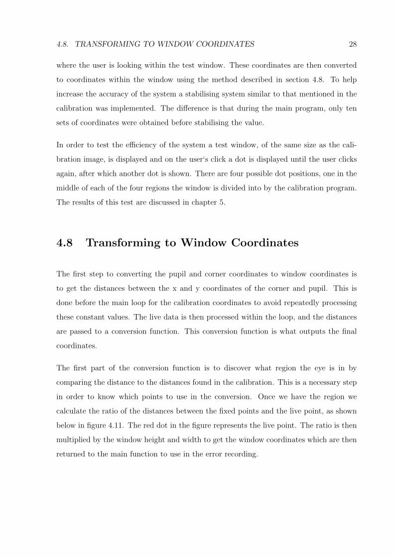
4.8 Transforming to Window Coordinates
The first step to converting the pupil and corner coordinates to window coordinates is
to get the distances between the x and y coordinates of the corner and pupil. This is
done before the main loop for the calibration coordinates to avoid repeatedly processing
these constant values. The live data is then processed within the loop, and the distances
are passed to a conversion function. This conversion function is what outputs the final
coordinates.
The first part of the conversion function is to discover what region the eye is in by
comparing the distance to the distances found in the calibration. This is a necessary step
in order to know which points to use in the conversion. Once we have the region we
calculate the ratio of the distances between the fixed points and the live point, as shown
below in figure 4.11. The red dot in the figure represents the live point. The ratio is then
multiplied by the window height and width to get the window coordinates which are then
returned to the main function to use in the error recording.

4.9. SUMMARY 29
Figure 4.11: Diagram of Distance Ratio’s
4.9 Summary
This chapter focused on how the gaze system was implemented. The design is similar to
other systems but the techniques used between systems vary largely. As such this system
outlined exactly how each step in the design was implemented and which main OpenCV
methods were used.
Many problems were found in the actual implementation and were largely solved using
techniques found through further research or through error reduction using redundancy.

Chapter 5
Results
As mentioned previously in section 4.7, the error is measured using four test dots on the
screen and comparing the positions received from the system to the dot coordinates. The
results of the testing are given in this chapter, with a brief discussion, followed by the
known limitations of the system.
5.1 Testing
The system output was limited to which region the user was focusing on. The error was
measured in the distance from the center of the drawn test circle to the calculated position
of the user’s gaze.
5.1.1 Results
An example of the system console output is shown below in figure 5.1.
The majority of the output in figure 5.1 is simply error checking but the line showing the
gaze region output shows the result of the system’s processing. This is the result shown
to the user. The actual error results are recorded separately in a .csv file by the system.
30

5.1. TESTING 31
Figure 5.1: Sample Console Output
The results below in table 5.1 are a sample of the error results taken from the testing
phase. The full table can be found in appendix A.
Table 5.1: Table of results for point in Region 1
Dot X Dot Y Error in X Error in Y Error
Point 1475 250 142 166 218475 250 147 115 187475 250 27 115 118475 250 79 132 154475 250 283 38 286475 250 159 55 168475 250 57 200 208475 250 47 106 120475 250 108 13 109475 250 283 191 341475 250 249 183 309475 250 159 98 187475 250 210 89 228475 250 244 183 305475 250 210 191 284475 250 300 123 324475 250 181 149 234475 250 147 55 157475 250 91 38 99475 250 164 98 191
The first two columns of the table below show the coordinates of the point the user is
looking at. The second two show the error in the x and y directions and the finally the
error using Pythagoras’ formula is given in the final column.
All error is measured in pixel values in the window space. The top left of the window
is (0,0) and the bottom right value is (1900,1000). As can be seen, the system does not
provide reliable results. The error jumps fairly erratically, but still lies within the correct

5.1. TESTING 32
region. The maximum error for the system was calculated to be 341 pixels and the average
error was 198 pixels. This means that the system accurately determine the user’s gaze
within a radius of approximately 350 pixels.
It was also found during the testing that the optimum head placement for the Face and
Eye detection stages is approximately 30cm in front of the camera and close to the same
height. With the head placed larger distances away and lower heights the face detection
and eye detection stages would fail up to 7 out of 10 times which affects the real time
nature of the system severely. In this optimum position the Face and Eye detection stages
only failed, on average, 1 out of 10 times. If the detection stage failed then the system
would restart the loop steps mentioned in section 3.4. Since the system implemented
an averaging system, as discussed in section 4.7, that requires the full loop to occur a
certain number of times before a position is calculated, this failure in the detection stages
can cause a huge delay in the real time nature of the system. This can be avoided by
maintaining the specified head position.
5.1.2 Discussion
The results of this system showed a large error inherent in the implementation. This error
could be from several sources.
Firstly, the pupil detection method was found to be inaccurate to the point of finding
the wrong point more than a third of the time. To counter this, the system used an
aggregating system, as mentioned previously, to find where the majority of pupil center
locations were found, which better approximated the correct position from a set of points.
While allowing the system to detect which region the gaze was in, this technique did
not sufficiently decrease the error. A higher resolution camera could help with this by
increasing the relative distance between the pupil and corner, but this could be resolved
through techniques like interpolation to resize the image as well. Several alternative
techniques to pupil detection are discussed in [3] and were found to be accurate enough
for use in human-computer interfacing. These techniques, as well as the testing, were

5.2. KNOWN LIMITATIONS 33
all implemented using regular web-cameras, which suggests that the problem with this
system’s pupil detection is the technique rather than the hardware. However, infrared
cameras, in conjunction with an infrared light, do have better accuracy, on average, than
those of a regular web-camera.
Secondly, the corner as a feature to track introduced several problems in the implemen-
tation and further increased the error despite the alleviating steps taken. As previously
mentioned, the system in [5] uses the bridge of the nose, and several other static points,
as additional features to track and this could remove several of the problems created and
alleviate the error in the result by minimising the error in the corner detection. Alterna-
tively, a better technique, like the one used in [26], could be used to detect the location
of the corner.
Finally, due to the requirement for the averaging of the coordinate sets, the system ran at
a slower rate than intended. The delay between the system getting stabilised coordinates
became variable, based on if any of the techniques failed. The best case was nearly un-
noticeable delay between successive readings to the worst case of several seconds between
readings. Also, as previously mentioned, this delay is dependent on the head being in the
optimal position.
Several other limitations that did not affect the system’s results were discovered during
testing.
5.2 Known Limitations
Since the system is designed to be simple, there are certain limitations that either intro-
duce a large error, or simply limit the system.
5.2.1 Design Choices
As previously mentioned in chapter 3, the system doesn’t deal with head movement
cancellation. So the user is required to keep their head still during calibration and any

5.3. SUMMARY 34
change in head orientation during the main program will result in a large error in the
position detection until the head is placed back in the same position and orientation.
5.2.2 Implementation Choices
Using the Haar detection as the face detection means that any differences from the main
cascade in the pixel group intensities causes the system to be unable to find the face. So
any user with dark skin will be unable to use the system.
The system is implemented in Windows and Microsoft Visual Studio. As such the system
only works in a windows context. The algorithm however is not OS specific and can be
implemented in any Operating System (OS) and indeed any language, though the code
listings given in appendix C will only work in a C++ environment with OpenCV installed.
5.3 Summary
Within the capabilities of the system, the error is still rather large. However the system
can still determine the region of the user’s focus. This still leaves a great many applications
available for the system. Another benefit of gaze tracking systems, and in particular the
design of this system, is that the modular nature of the design allows techniques to be
replaced with better techniques, which are available, with relative ease. This means the
system can be upgraded quickly and effectively.

Chapter 6
Conclusion
The aim of this project was to create a Gaze tracking system using a regular web camera
and the OpenCV library. As has been shown in chapters 4 and 5, the system has been
created. However, whether the system is actually effective needs to be determined. This
chapter will also discuss possible future work.
6.1 Effectiveness of the System
The error results obtained in chapter 5 show that the system was ineffective. Considering
the simple nature of the implementation, it is possible that this is the cause. This result
is still inconclusive on whether or not it is feasible to create an effective gaze tracking
system using only a regular web camera.
As discussed in section 5.2, the system has been designed simply and this has affected its
strength. The research in chapter 2, and as discussed in section 5.1.2, shows that other
techniques are available and have produced better results in many cases. This means
that an effective gaze tracking system using a regular, or a simple infrared, camera is
possible to create, despite the inconclusive nature of this system. This removes the need
for contact and invasive systems and can remove the need for head mounted gear as well.
35

6.2. FUTURE WORK 36
This thesis has aimed to show it is possible to create a system that uses a regular web
camera to effectively track the gaze of the user and though this system is inaccurate, the
high error can be attributed to poor techniques rather than the need for better hardware.
Having further uncovered several techniques that can replace the ones used in this system
and have been found to have much better performance, the conclusion of this thesis is that
an efficient and accurate gaze tracking system can be created with a simple web camera.
6.2 Future Work
As discussed in section 1.1, the applications of gaze tracking are varied and extremely
interesting. To create systems effective and efficient enough for these application is the
goal of the work in this field. As such, possible future works for this project include:
• Finding better techniques through technique comparisons
• Removing the need for calibration
• Incorporating head movement cancellation
• Implementing a gaze tracker using a web-camera and a Raspberry Pi
• Implementing the system on a GPU

Bibliography
[1] Baluja, S., and Pomerleau, D. Non-intrusive gaze tracking using artificial
neural networks. Tech. rep., Pittsburgh, PA, USA, 1994.
[2] Buscher, G., Cutrell, E., and Morris, M. R. What do you see when you’re
surfing?: using eye tracking to predict salient regions of web pages. In Proceedings
of the 27th international conference on Human factors in computing systems (New
York, NY, USA, 2009), CHI ’09, ACM, pp. 21–30.
[3] Ciesla Michal, K. P. Eye Pupil Location Using Webcam. Online. Accessed on 31
October 2012. Available from: http://arxiv.org/ftp/arxiv/papers/1202/1202.
6517.pdf.
[4] CodeBox. opencv - Iris Detection. Online, November 2010. Accessed on 26 October
2012. Available from: http://codingbox.net/jinstall/index.php?option=com_
content&view=section&layout=blog&id=3&Itemid=16.
[5] Frieslaar, I. Moving the mouse pointer using eye gazing. Published through
Department of Computer Science, University of the Western Cape, 2011.
[6] Gao, D., Yin, G., Cheng, W., and Feng, X. Non-invasive eye tracking tech-
nology based on corneal reflex. Procedia Engineering 29, 0 (2012), 3608 – 3612. 2012
International Workshop on Information and Electronics Engineering.
[7] Grossberg, S., Srihasam, K., and Bullock, D. Neural dynamics of saccadic
and smooth pursuit eye movement coordination during visual tracking of unpre-
dictably moving targets. Neural Networks 27, 0 (2012), 1 – 20.
37

BIBLIOGRAPHY 38
[8] Huang, Y., Wang, Z., and Ping, A. Non-contact gaze tracking with head
movement adaptation based on single camera, 2009.
[9] Huang Ying, W. Z., and Xuyan, T. A real-time compensation strategy for non-
contact gaze tracking under natural head movement. Chinese Journal of Electronics
19 (July 2010), 446–450.
[10] Husken, M., Igel, C., and Toussaint, M. Task-dependent evolution of modu-
larity in neural networks. Connection Science 14 (2002), 2002.
[11] Jacob, R. J. K. The use of eye movements in human-computer interaction tech-
niques: What you look at is what you get. ACM Transactions on Information
Systems 9 (1991), 152–169.
[12] Jacob, R. J. K. Eye tracking in advanced interface design, 1995.
[13] Kawato, S., and Tetsutani, N. Detection and tracking of eyes for gaze-camera
control. Image and Vision Computing 22, 12 (2004), 1031 – 1038. Proceedings from
the 15th International Conference on Vision Interface.
[14] Klingenhoefer, S., and Bremmer, F. Saccadic suppression of displacement in
face of saccade adaptation. Vision Research 51, 8 (2011), 881 – 889. Perception and
Action: Part II.
[15] Li, D., Babcock, J., and Parkhurst, D. J. openeyes: a low-cost head-mounted
eye-tracking solution. In Proceedings of the 2006 symposium on Eye tracking research
& applications (New York, NY, USA, 2006), ETRA ’06, ACM, pp. 95–100.
[16] Li, D., Winfield, D., and Parkhurst, D. J. Starburst: A hybrid algorithm
for video-based eye tracking combining feature-based and model-based approaches.
In Proceedings of the 2005 IEEE Computer Society Conference on Computer Vision
and Pattern Recognition (CVPR’05) - Workshops - Volume 03 (Washington, DC,
USA, 2005), CVPR ’05, IEEE Computer Society, pp. 79–.
[17] Mauri, C., and Lors, J. Computer vision interaction for people with severe
movement restrictions.

BIBLIOGRAPHY 39
[18] Morimoto, C. H., and Mimica, M. R. Eye gaze tracking techniques for interac-
tive applications. Computer Vision and Image Understanding 98, 1 (2005), 4 – 24.
Special Issue on Eye Detection and Tracking.
[19] Ohno, T., and Mukawa, N. A free-head, simple calibration, gaze tracking system
that enables gaze-based interaction. In Proceedings of the 2004 symposium on Eye
tracking research & applications (New York, NY, USA, 2004), ETRA ’04, ACM,
pp. 115–122.
[20] Rayner, K. Eye movements in reading and information processing: 20 years of
research. Psychological Bulletin (1998), 372–422.
[21] Reichle, E. D., Pollatsek, A., Fisher, D. L., and Rayner, K. Toward a
model of eye movement control in reading. PSYCHOLOGICAL REVIEW 105, 1
(1998), 125–157.
[22] San Agustin, J., Skovsgaard, H., Mollenbach, E., Barret, M., Tall,
M., Hansen, D. W., and Hansen, J. P. Evaluation of a low-cost open-source
gaze tracker. In Proceedings of the 2010 Symposium on Eye-Tracking Research &
Applications (New York, NY, USA, 2010), ETRA ’10, ACM, pp. 77–80.
[23] Sewell, W., and Komogortsev, O. Real-time eye gaze tracking with an un-
modified commodity webcam employing a neural network. In Proceedings of the 28th
of the international conference extended abstracts on Human factors in computing
systems (New York, NY, USA, 2010), CHI EA ’10, ACM, pp. 3739–3744.
[24] Sibert, L. E., and Jacob, R. J. K. Evaluation of eye gaze interaction. In
Proceedings of the SIGCHI conference on Human factors in computing systems (New
York, NY, USA, April 2000), CHI ’00, ACM, pp. 281–288.
[25] Tock, D., and Craw, I. Tracking and measuring drivers’ eyes. Image and Vision
Computing 14, 8 (1996), 541 – 547. 6th British Machine Vision Conference.

BIBLIOGRAPHY 40
[26] Torricelli, D., Conforto, S., Schmid, M., and DAlessio, T. A neural-
based remote eye gaze tracker under natural head motion. Computer Methods and
Programs in Biomedicine 92, 1 (2008), 66 – 78.
[27] Wilson, P. I., and Fernandez, J. Facial feature detection using haar classifiers.
J. Comput. Sci. Coll. 21, 4 (Apr. 2006), 127–133.
[28] Zhu, Z., Ji, Q., and Member, S. Novel eye gaze tracking techniques under natural
head movement.

Appendix A
Full Table of results
Table A.1: First Table of results for points
Dot X Dot Y Error in X Error in Y Error
Point 1475 250 142 166 218475 250 147 115 187475 250 27 115 118475 250 79 132 154475 250 283 38 286475 250 159 55 168475 250 57 200 208475 250 47 106 120475 250 108 13 109475 250 283 191 341475 250 249 183 309475 250 159 98 187475 250 210 89 228475 250 244 183 305475 250 210 191 284475 250 300 123 324475 250 181 149 234475 250 147 55 157475 250 91 38 99475 250 164 98 191
41

APPENDIX A. FULL TABLE OF RESULTS 42
Table A.2: Second Table of results for points
Dot X Dot Y Error in X Error in Y Error
Point 21325 250 210 72 2221325 250 227 72 2381325 250 227 72 2381325 250 244 149 2861325 250 181 64 1921325 250 266 30 2681325 250 198 157 2531325 250 193 17 1941325 250 23 191 1921325 250 147 19 1481325 250 130 16 1311325 250 74 149 1661325 250 74 38 831325 250 193 47 1991325 250 11 174 1741325 250 125 30 1291325 250 79 200 2151325 250 249 45 2531325 250 215 64 2241325 250 300 89 313
Point 31325 750 79 140 1611325 750 40 140 1461325 750 113 47 1221325 750 74 132 1511325 750 62 81 1021325 750 96 55 1111325 750 295 65 3021325 750 159 21 1601325 750 96 23 991325 750 79 157 1761325 750 249 106 2711325 750 91 174 1961325 750 147 123 1921325 750 227 30 2291325 750 57 30 641325 750 45 132 1391325 750 159 157 2231325 750 164 30 1671325 750 27 64 691325 750 23 64 68

APPENDIX A. FULL TABLE OF RESULTS 43
Table A.3: Third Table of results for points
Dot X Dot Y Error in X Error in Y Error
Point 4475 750 17 183 184475 750 159 183 242475 750 142 149 206475 750 142 98 173475 750 261 98 279475 750 215 191 288475 750 96 174 199475 750 108 106 151475 750 28 81 86475 750 215 81 230475 750 130 21 132475 750 74 174 189475 750 57 55 79475 750 283 21 284475 750 232 174 290475 750 210 55 217475 750 244 64 252475 750 295 149 330475 750 261 200 329475 750 176 30 179

Appendix B
Installing OpenCV
OpenCV is an open source computer vision library dedicated to easing the implementation
of computer vision related programs. It is an extensive library, the whole library for version
2.4.2 exceeding 6GB of space after installation . As such the install will be included in
the hand in and instructions on how to use the library will be given below.
B.1 Installing in Windows
Installing OpenCV in windows is a fairly simple process. However, to make linking the
library in your projects easier, it is useful to add some additional steps. 1
The first step is to download the OpenCV installation for windows.2 Then the installation
must be run by and the library extracted to a path. In order to simplify the linking later
on it is necessary to add certain OpenCV folders to your system path. The folders under
the variable “path” are:
\build\x86\vc10\bin
\build\common\tbb\ia32\vc10
1Please note that these instructions are a combination of the instructions found at http:
//jepsonsblog.blogspot.com/2012/07/installation-guide-opencv-24-with.html and http://
stackoverflow.com/questions/10901905/installing-opencv-2-4-in-visual-c-2010-express2The file can be downloaded from http://sourceforge.net/projects/opencvlibrary/
44

B.2. LINKING YOUR VISUAL STUDIO PROJECT 45
This completes the setup of OpenCV in windows. Next is to link a project in Visual
C++. It is important to note that the paths here are excluding the actual reference to
where you have extracted OpenCv to. An example that includes the extraction path is
C:\opencv\build\x86\vc10\bin
B.2 Linking your Visual Studio Project
Once you have created a project in Visual C++, it is necessary to edit the properties of
the project. Under the tab, VC++ Directories, it is necessary to include the directories
shown below under the Include directories.
build\include\opencv
build\include
Under the Library directories it is necessary to include the build directory that corresponds
to your system. In the case of this system the directory was:
build\x86\vc10\lib
Under the heading Linker-Input-Additional Dependencies the following files were required
to be added.
opencv_calib3d242d.lib
opencv_contrib242d.lib
opencv_core242d.lib
opencv_features2d242d.lib
opencv_flann242d.lib
opencv_gpu242d.lib

B.2. LINKING YOUR VISUAL STUDIO PROJECT 46
opencv_highgui242d.lib
opencv_imgproc242d.lib
opencv_legacy242d.lib
opencv_ml242d.lib
opencv_nonfree242d.lib
opencv_objdetect242d.lib
opencv_photo242d.lib
opencv_stitching242d.lib
opencv_ts242d.lib
opencv_video242d.lib
opencv_videostab242d.lib
It is important to note that firstly the 242 is for version 2.4.2 of OpenCV and the ap-
propriate number should be inserted as required. Secondly, these files are for the debug
solution. For the release solution the “d” at the end of the filename should be removed.
It is recommended to test the settings by creating a short test project.

Appendix C
Code Listings
C.1 Face Detection
IplImage* detectFace(IplImage *img,CvHaarClassifierCascade *cascade_f,
CvMemStorage *storage){
/* detect faces */
CvSeq *faces = cvHaarDetectObjects(
img, /* the source image */
cascade_f, /* the face classifier */
storage, /* memory buffer, created with cvMemStorage */
1.2, 3, 0, /* special parameters, tune for your app*/
cvSize(40, 40) /* minimum detection scale */
);
/* return if not found */
if (faces->total == 0){ flag = false;return img;}
//this flag serves to tell the program that the facial detection has crashed
/* get the first detected face */
47

C.1. FACE DETECTION 48
CvRect *face = (CvRect*)cvGetSeqElem(faces, 0);
/* draw a red rectangle */
cvRectangle(
img,
cvPoint(face->x, face->y),
cvPoint(
face->x + face->width,
face->y + face->height
),
CV_RGB(255, 0, 0),
1, 8, 0
);
// cvShowImage("Checking", img);
/* reset buffer for the next object detection */
cvClearMemStorage(storage);
/* Set the Region of Interest: estimate the eyes’ position */
cvSetImageROI(
img, /* the source image */
cvRect(
face->x, /* x = start from leftmost */
face->y + (face->height*0.1), /* y = a few pixels from the top */
face->width, /* width = same width with the face */
face->height*0.5 /* height = 1/3 of face height */
)
);
/* create destination image
Note that cvGetSize will return the width and the height of ROI */
IplImage *Region = cvCreateImage(cvGetSize(img), img->depth, img->nChannels);

C.2. EYES DETECTION 49
/* copy subimage */
cvCopy(img, Region);
/* reset region of interest */
cvResetImageROI(img);
cvClearMemStorage(storage);
return Region;
}
C.2 Eyes Detection
This method detects a single eye and is called seperately for each eye.
IplImage* detectEye(IplImage *img,CvHaarClassifierCascade *cascade_e,CvMemStorage *storage)
{
cvClearMemStorage(storage);
/* detect faces */
CvSeq *eyes = cvHaarDetectObjects(
img, /* the source image */
cascade_e, /* the face classifier */
storage, /* memory buffer, created with cvMemStorage */
1.1, 3, 0, /* special parameters, tune for your app*/
cvSize(40, 40) /* minimum detection scale */
);
/* return if not found */
if (eyes->total == 0){flag = false; return img;}
/* get the first detected face */

C.2. EYES DETECTION 50
CvRect *eye = (CvRect*)cvGetSeqElem(eyes, 0);
/* draw a red rectangle */
cvRectangle(
img,
cvPoint(eye->x, eye->y),
cvPoint(eye->x + eye->width, eye->y + eye->height),
CV_RGB(255, 0, 0),
1, 8, 0
);
//cvShowImage("Checking",img);
/* reset buffer for the next object detection */
cvClearMemStorage(storage);
/* Set the Region of Interest: estimate the eyes’ position */
cvSetImageROI(
img, /* the source image */
cvRect(
eye->x /* x = start from leftmost */
,eye->y+ eye->height*0.33 /* y = a few pixels from the top */
,eye->width /* width = same width with the eye */
,eye->height*0.67 /* height = 1/3 of eye height */
)
);
IplImage *Region = cvCreateImage(cvGetSize(img),
img->depth,
img->nChannels);
/* copy subimage */

C.3. FINDING CENTER OF THE PUPIL 51
cvCopy(img, Region);
/* reset region of interest */
cvResetImageROI(img);
cvClearMemStorage(storage);
return Region;
}
C.3 Finding Center of the pupil
float * detectPupil(IplImage * img, CvMemStorage *storage){
//function to detect the center of the pupils
float coords[2];
IplImage* edgeImage = cvCreateImage(cvGetSize(img),img->depth,
img->nChannels);
IplImage *smoothImage = cvCreateImage(cvGetSize(img),
img->depth,
img->nChannels);
cvClearMemStorage(storage);
cvEqualizeHist(img, smoothImage);
cvAddS(smoothImage, cvScalar(70,70,70), smoothImage);
cvThreshold(smoothImage,smoothImage, 120,255,CV_THRESH_BINARY);
cvSmooth(smoothImage , smoothImage, CV_GAUSSIAN, 3,0);
CvSeq* circles = cvHoughCircles(smoothImage, storage,
CV_HOUGH_GRADIENT, 2, edgeImage->height,35,25);
if(circles->total == 0){flag = false; return coords;}

C.4. FINDING THE CORNER 52
int i;
//cout<<circles->total <<" is the total number of circles" <<endl;
for (i = 0; i < circles->total; i++)
{
float* p = (float*)cvGetSeqElem( circles, i );
coords[0] = p[0];
coords[1] = p[1];
}
return coords;
}//end of detect pupils
C.4 Finding the Corner
float * detectCorner(IplImage * img,bool left){
float coords[2];
int cornerC = 1;
CvPoint2D32f corners[1] = {0};
int width,x,y,height;
//this flag is to deterimine whethere this is the left eye or not
//The if statment reduces the ROI so that we remove most false positives
if (left){
width = (int)img->width*0.2;
x = 0;
y = img->height*0.4;
height = img->height*0.2;
}else{
width = (int)img->width*0.2;
x =(int) img->width*0.75;
y = img->height*0.4;
height = img->height*0.3;

C.4. FINDING THE CORNER 53
}
cvSetImageROI(
img,
cvRect(
x,
y ,
width,
height
)
);
//reduced the noise
cvEqualizeHist(img, img);
IplImage * eig_image = cvCreateImage(cvGetSize(img),
IPL_DEPTH_32F, 1);
IplImage * temp = cvCreateImage(cvGetSize(img),
IPL_DEPTH_32F, 1);
//This method does most of the work
cvGoodFeaturesToTrack(img,eig_image,temp,corners, &cornerC, 0.5,img->width);
/*
The addition of the x and y is to offset the reduced area of the ROI
so that the coordinates returned are in the same reference frame
as the pupil coordinates
*/
coords[0] = corners[0].x + x;
coords[1] = corners[0].y + y;
cvResetImageROI(img);
return coords;