gateways for canopen - electrical and industrial power ...pub/@electrical/documents/conte… ·...
TRANSCRIPT
User Manual XI/ON10/2011 MN05002005Z-EN
replaces M001768-03, 11/2007
Gateways for
CANopen
ManufacturerEaton Automation AGSpinnereistrasse 8-14CH-9008 St. GallenSwitzerlandwww.eaton-automation.com www.eaton.com
Support
Original manualThe German version of this document is the original manual.
Translations of the original manualAll non-German editions of this document are translations of the originalmanual.
Editorial departmentMonika Jahn
Brand and product namesAll brand and product names are trademarks or registered trademarks of theowner concerned.
Copyright© Eaton Automation AG, CH-9008 St. Gallen
All rights reserved, also for the translation.
None of this document may be reproduced or processed, duplicated or distrib-uted by electronic systems in any form (print, photocopy, microfilm or anyother process) without the written permission of Eaton Automation AG,St. Gallen.
Subject to modifications.
Region North AmericaEaton CorporationElectrical Sector1111 Superior Ave.Cleveland, OH 44114United States877-ETN-CARE (877-386-2273)www.eaton.com
Other regionsPlease contact your supplier or send an E-Mail to:[email protected]
Imprint
2 XI/ON: Gateways for CANopen 10/2011 MN05002005Z-EN www.eaton.com
Before commencing the installation
• Disconnect the power supply of the device.
• Ensure that the device cannot be acci-dentally restarted.
• Verify isolation from the supply.
• Earth and short circuit.
• Cover or enclose neighbouring units that are live.
• Follow the engineering instructions of the device concerned.
• Only suitably qualified personnel in accordance with EN 50110-1/-2 (DIN VDE 0105 Part 100) may work on this device.
• Before installation and before touching the device ensure that you are free of electrostatic charge.
• The functional earth (FE) must be connected to the protective earth (PE) or tothe potential equalisation. The system installer is responsible for implementing this connection.
• Connecting cables and signal lines should be installed so that inductive or capacitive interference do not impair the automation functions.
• Install automation devices and related operating elements in such a way that they are well protected against uninten-tional operation.
• Suitable safety hardware and software measures should be implemented for the I/O interface so that a line or wire breakage on the signal side does not
result in undefined states in the auto-mation devices.
• Ensure a reliable electrical isolation of the low voltage for the 24 volt supply. Only use power supply units complying with IEC/HD 60364-4-41 (DIN VDE 0100 Part 410).
• Deviations of the mains voltage from the rated value must not exceed the tolerance limits given in the specifica-tions, otherwise this may cause malfunction and dangerous operation.
• Emergency stop devices complying with IEC/EN 60204-1 must be effective in all operating modes of the automa-tion devices. Unlatching the emer-gency-stop devices must not cause uncontrolled operation or restart.
• Measures should be taken to ensure the proper restart of programs inter-rupted after a voltage dip or failure. This should not cause dangerous operating states even for a short time. If neces-sary, emergency-stop devices should be implemented.
• Wherever faults in the automation system may cause damage to persons or property, external measures must be implemented to ensure a safe operating state in the event of a fault or malfunc-tion (for example, by means of separate limit switches, mechanical interlocks etc.).
Warning!Dangerous electrical voltage!
Safety regulations
XI/ON: Gateways for CANopen 10/2011 MN05002005Z-EN www.eaton.com 3
• The electrical installation must be carried out in accordance with the rele-vant regulations (e.g. with regard to cable cross sections, fuses, PE).
• All work relating to transport, installa-tion, commissioning and maintenance must only be carried out by qualified personnel. (IEC/HD 60364 (DIN VDE 0100) and national work safety regulations).
Safety regulations
4 XI/ON: Gateways for CANopen 10/2011 MN05002005Z-EN www.eaton.com
Table of contents
Table of contents
Table of contents . . . . . . . . . . . . . . . . . . . . . . . . . . . . 5
1 XI/ON gateways for CANopen . . . . . . . . . . . . . . . . . 9Function . . . . . . . . . . . . . . . . . . . . . . . . . . . . . . . . . . . . . 9Versions . . . . . . . . . . . . . . . . . . . . . . . . . . . . . . . . . . . . 10
2 XN standard gateways . . . . . . . . . . . . . . . . . . . . . . 11Gateway XN-GW-CANopen. . . . . . . . . . . . . . . . . . . . . 11Gateway XN-GWBR-CANopen . . . . . . . . . . . . . . . . . . 12Technical data . . . . . . . . . . . . . . . . . . . . . . . . . . . . . . . 13– Structure of a XN standard gateway . . . . . . . . . . . 13– Technical data for the XN station . . . . . . . . . . . . . . 13– Technical data for the terminals of XN standard
gateways and base modules . . . . . . . . . . . . . . . . . 17– Technical data for XN-GW-CANopen . . . . . . . . . . . 18– Technical data for XN-GWBR-CANopen . . . . . . . . . 20Connections at XN-GW-CANopen. . . . . . . . . . . . . . . . 22– Field bus termination via SUB-D sockets . . . . . . . . 22– Field bus connection through direct wiring . . . . . . . 24Connections at XN-GWBR-CANopen . . . . . . . . . . . . . 27– Power supply . . . . . . . . . . . . . . . . . . . . . . . . . . . . . . 27– Field bus connection via open style connector . . . . 28Service interface connection . . . . . . . . . . . . . . . . . . . . 31– Connection with XI/ON cable . . . . . . . . . . . . . . . . . 31Setting the bit transfer rate via DIP switches . . . . . . . 33Node-ID setting . . . . . . . . . . . . . . . . . . . . . . . . . . . . . . 35Acceptance of the XI/ON configuration . . . . . . . . . . . 38Diagnostics LED indications . . . . . . . . . . . . . . . . . . . . 40
3 XNE ECO gateway . . . . . . . . . . . . . . . . . . . . . . . . . . 45Gateway XNE-GWBR-CANopen . . . . . . . . . . . . . . . . . 45Technical data . . . . . . . . . . . . . . . . . . . . . . . . . . . . . . . 46– Structure of a XNE ECO gateway . . . . . . . . . . . . . . 46– Technical data for the XNE station . . . . . . . . . . . . . 46– Approvals and tests for a XI/ON station . . . . . . . . . 50
XI/ON: Gateways for CANopen 10/2011 MN05002005Z-EN www.eaton.com 5
Table of contents
– Technical Data for the Push-in tensionclamp terminals . . . . . . . . . . . . . . . . . . . . . . . . . . . . 51
Connections at XNE-GWBR-CANopen . . . . . . . . . . . . 52– Voltage Supply . . . . . . . . . . . . . . . . . . . . . . . . . . . . 52– Field bus connection via Push-in tension clamp
terminals . . . . . . . . . . . . . . . . . . . . . . . . . . . . . . . . . 53Service interface connection . . . . . . . . . . . . . . . . . . . . 54– Connection with XI/ON cable . . . . . . . . . . . . . . . . . 54Setting the Node-ID. . . . . . . . . . . . . . . . . . . . . . . . . . . 56Setting the bit rate. . . . . . . . . . . . . . . . . . . . . . . . . . . . 58Activating the bus terminating resistor. . . . . . . . . . . . 59Acceptance of the XI/ON station configuration . . . . . 60Diagnostic messages via LEDs . . . . . . . . . . . . . . . . . . 61Maximum station extension . . . . . . . . . . . . . . . . . . . . 64
4 Communication in CANopen . . . . . . . . . . . . . . . . . 67General. . . . . . . . . . . . . . . . . . . . . . . . . . . . . . . . . . . . . 67Communication . . . . . . . . . . . . . . . . . . . . . . . . . . . . . . 68– Types of telegram messages
(Communication Objects) . . . . . . . . . . . . . . . . . . . . . 69XI/ON and CANopen . . . . . . . . . . . . . . . . . . . . . . . . . . 71Electronic data sheet – EDS file . . . . . . . . . . . . . . . . . 72Setting up communication. . . . . . . . . . . . . . . . . . . . . . 73– Minimum Boot-up . . . . . . . . . . . . . . . . . . . . . . . . . . 73– Identifier for the standard objects . . . . . . . . . . . . . . 77– Setting up Node Guarding protocol . . . . . . . . . . . . . 80XI/ON emergency messages . . . . . . . . . . . . . . . . . . . . 83– Boot-up message . . . . . . . . . . . . . . . . . . . . . . . . . . 89Parameterization by meansof Service Data Objects (SDO). . . . . . . . . . . . . . . . . . . 91– Read (Read from Object Dictionary) . . . . . . . . . . . . 92– Write (Write to Object Dictionary). . . . . . . . . . . . . . 93– Commanded parameter storing / restoring . . . . . . 95Transmission of Process Data Objects (PDO) . . . . . . . 96– Communication parameter COB-ID . . . . . . . . . . . . . 96– Transmission Type . . . . . . . . . . . . . . . . . . . . . . . . . 97– Inhibit Time . . . . . . . . . . . . . . . . . . . . . . . . . . . . . . . 98– Event Time . . . . . . . . . . . . . . . . . . . . . . . . . . . . . . . 99– Available PDOs . . . . . . . . . . . . . . . . . . . . . . . . . . . . 99– Mapping of objects in PDOs . . . . . . . . . . . . . . . . . 100
6 XI/ON: Gateways for CANopen 10/2011 MN05002005Z-EN www.eaton.com
Table of contents
– Default PDOs and PDO mappings . . . . . . . . . . . . . 101– Mappable objects . . . . . . . . . . . . . . . . . . . . . . . . . 107– Procedure for altering PDO mappings . . . . . . . . . . 109
5 Object dictionary for XI/ON in CANopen . . . . . . 111Overview of all objects . . . . . . . . . . . . . . . . . . . . . . . 111Object overview of the communication profile . . . . . 116Information about the XI/ON station. . . . . . . . . . . . . 120– Object 1000hex Device Type . . . . . . . . . . . . . . . . 120– Object 1008hex Device Name . . . . . . . . . . . . . . . 120– Object 1009hex Manufacturer Hardware Version 121– Object 100Ahex Manufacturer Software Version 122– Object 1018hex Identity Object . . . . . . . . . . . . . . 123– Object 1020hex Verify Configuration. . . . . . . . . . . 126– Object 1027hex Module List . . . . . . . . . . . . . . . . . 128Error Register . . . . . . . . . . . . . . . . . . . . . . . . . . . . . . . 129– Object 1001hex Error Register . . . . . . . . . . . . . . . 129Monitoring of operational readiness. . . . . . . . . . . . . 130– Object 100Chex Guard Time . . . . . . . . . . . . . . . . . 130– Object 100Dhex Life Time Factor. . . . . . . . . . . . . . 131– Object 1016hex Consumer Heartbeat Time. . . . . . 132– Object 1017hex Producer Heartbeat Time. . . . . . . 134“Store/Load Parameters” commands . . . . . . . . . . . . 135– Object 1010hex Store Parameters . . . . . . . . . . . . 137– Object 1011hex Restore Default Parameters . . . . 138Identifiers of Synchronization and Emergency . . . . . 139– Object 1005hex Sync COB-ID . . . . . . . . . . . . . . . . 139– Object 1014hex Emcy COB-ID . . . . . . . . . . . . . . . . 140Transfer of service data. . . . . . . . . . . . . . . . . . . . . . . 142– Objects 1200hex to 1203hex
Server SDO Parameters . . . . . . . . . . . . . . . . . . . . 142Transfer of process output data . . . . . . . . . . . . . . . . 144– Objects 1400hex to 141Fhex
Receive PDO Parameters . . . . . . . . . . . . . . . . . . . 145– Objects 1600hex to 161Fhex
Receive PDO Mapping Parameters . . . . . . . . . . . . 149Transfer of process input data. . . . . . . . . . . . . . . . . . 153– Objects 1800hex to 181Fhex
Transmit PDO Parameters . . . . . . . . . . . . . . . . . . . 154
XI/ON: Gateways for CANopen 10/2011 MN05002005Z-EN www.eaton.com 7

Table of contents
– Objects 1A00hex to 1A1Fhex Transmit PDO Mapping Parameters . . . . . . . . . . . 159
Network management . . . . . . . . . . . . . . . . . . . . . . . . 163– Object 1F80hex NMT Startup . . . . . . . . . . . . . . . . 163– Object 1F81hex Slave Assignment . . . . . . . . . . . . 165– Object 1F82hex Request NMT. . . . . . . . . . . . . . . . 167– Object 1F83hex Request Guarding . . . . . . . . . . . . 169Manufacturer-specific objects. . . . . . . . . . . . . . . . . . 170– Object 2000hex Serial Number . . . . . . . . . . . . . . . 171– Object 2010hex Behaviour Modifiers . . . . . . . . . . 171– Object 2400hex System Voltages . . . . . . . . . . . . . 175Diagnostic messages. . . . . . . . . . . . . . . . . . . . . . . . . 176– Diagnostics messages via software . . . . . . . . . . . 176Maximum topology . . . . . . . . . . . . . . . . . . . . . . . . . . 180– Maximum system configuration
of a CANopen bus line . . . . . . . . . . . . . . . . . . . . . 180– Maximum bus length . . . . . . . . . . . . . . . . . . . . . . . 183Mixed operation with other types of station. . . . . . . 184
6 Coupling with automation equipment . . . . . . . . 185Commissioning the XI/ON station with MXpro. . . . . 185– Connection of programming PC, PLC and
CAN-XI/ON station . . . . . . . . . . . . . . . . . . . . . . . . 185– Starting MXpro and creating a new project . . . . . 185– Integrating the CAN master. . . . . . . . . . . . . . . . . . 186– Integrating the CAN slave . . . . . . . . . . . . . . . . . . . 190– Integrating the libraries
for CANopen communication. . . . . . . . . . . . . . . . . 197
Index . . . . . . . . . . . . . . . . . . . . . . . . . . . . . . . . . . . . . 199
8 XI/ON: Gateways for CANopen 10/2011 MN05002005Z-EN www.eaton.com

1 XI/ON gateways for CANopen
Function
1 XI/ON gateways for CANopen
Function XI/ON gateways for CANopen enable the opera-tion of XI/ON modules in a CANopen structure. The gateway is the link between the field bus neutral XI/ON modules and the other CANopen nodes. It handles the entire process data traffic between the I/O level and the field bus, and gener-ates the necessary diagnostics data. A service interface is used to provide information for the I/Oassistant software.
XI/ON: Gateways for CANopen 10/2011 MN05002005Z-EN www.eaton.com 9

1 XI/ON gateways for CANopen
Versions
Versions The gateways for the CANopen field bus system are available in the following versions:
Figure 1: Versions of the gateways for CANopen
• XN-GW-CANopen: XN standard gateway without integrated power supply module.
• XN-GWBR-CANopen: XN standard gateway with integrated power supply module.
• XNE-GWBR-CANopen: XNE ECO gateway with integrated power supply module.
XN-GW-CANopen: XN-GWBR-CANopen: XNE-GWBR-CANopen:
→ The XN-GW-CANopen gateway does not have an internal power supply module!
• Install a bus refreshing module with the corre-sponding base module as the first module after the gateway!
• XI/ON stations with XN-GW-CANopen can only be combined with XN standard modules.
10 XI/ON: Gateways for CANopen 10/2011 MN05002005Z-EN www.eaton.com
2 XN standard gateways
Gateway XN-GW-CANopen
2 XN standard gateways
Gateway XN-GW-CANopen
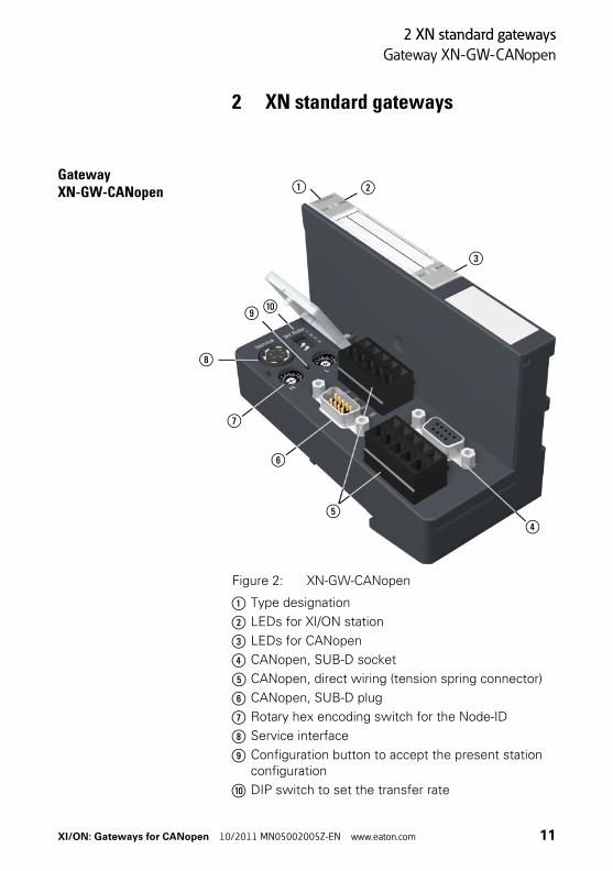
Figure 2: XN-GW-CANopen
a Type designation
b LEDs for XI/ON station
c LEDs for CANopen
d CANopen, SUB-D socket
e CANopen, direct wiring (tension spring connector)
f CANopen, SUB-D plug
g Rotary hex encoding switch for the Node-ID
h Service interface
i Configuration button to accept the present station configuration
j DIP switch to set the transfer rate
a b
c
de
f
g
h
i j
XI/ON: Gateways for CANopen 10/2011 MN05002005Z-EN www.eaton.com 11
2 XN standard gateways
Gateway XN-GWBR-CANopen
Gateway XN-GWBR-CANopen
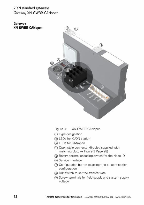
Figure 3: XN-GWBR-CANopen
a Type designation
b LEDs for XI/ON station
c LEDs for CANopen
d Open style connector (5-pole / supplied with matching plug, → Figure 9 Page 28)
e Rotary decimal encoding switch for the Node-ID
f Service interface
g Configuration button to accept the present station configuration
h DIP switch to set the transfer rate
i Screw terminals for field supply and system supply voltage
a b
c
d
e
fg
h
i
c
12 XI/ON: Gateways for CANopen 10/2011 MN05002005Z-EN www.eaton.com
2 XN standard gateways
Technical data
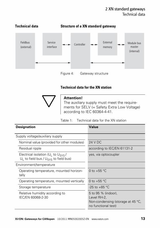
Technical data Structure of a XN standard gateway
Figure 4: Gateway structure
Technical data for the XN station
Table 1: Technical data for the XN station
Fieldbus
(external)
Serviceinterface
External
memoryModule bus
master(internal)
Controller
Attention!The auxiliary supply must meet the require-ments for SELV (= Safety Extra Low Voltage) according to IEC 60364-4-41.
Designation Value
Supply voltage/auxiliary supply
Nominal value (provided for other modules) 24 V DC
Residual ripple according to IEC/EN 61131-2
Electrical isolation (UL to USYS / UL to field bus / USYS to field bus)
yes, via optocoupler
Environment/temperature
Operating temperature, mounted horizon-tally
0 to +55 °C
Operating temperature, mounted vertically 0 to +55 °C
Storage temperature -25 to +85 °C
Relative humidity according to IEC/EN 60068-2-30
5 to 95 % (indoor), Level RH-2, Non-condensing (storage at 45 °C, no functional test)
XI/ON: Gateways for CANopen 10/2011 MN05002005Z-EN www.eaton.com 13
2 XN standard gateways
Technical data
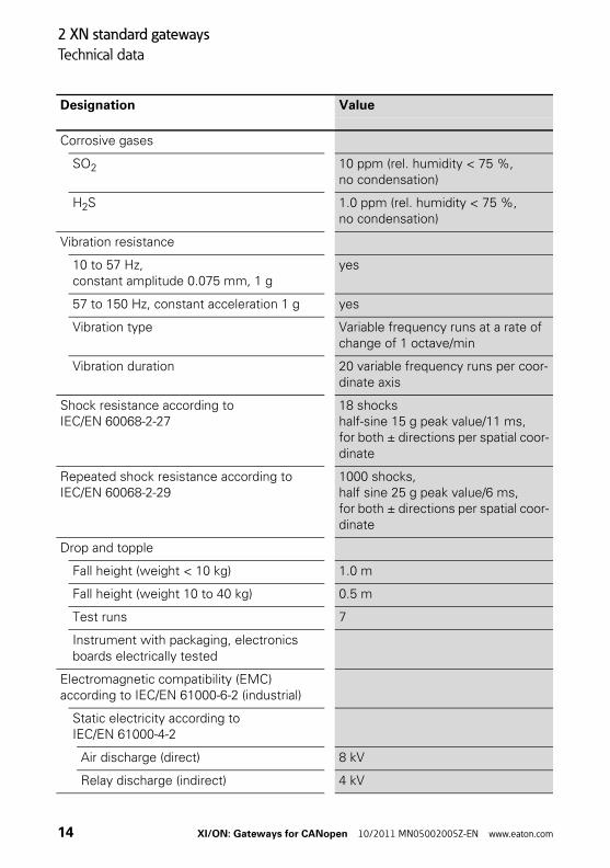
Corrosive gases
SO2 10 ppm (rel. humidity < 75 %, no condensation)
H2S 1.0 ppm (rel. humidity < 75 %, no condensation)
Vibration resistance
10 to 57 Hz, constant amplitude 0.075 mm, 1 g
yes
57 to 150 Hz, constant acceleration 1 g yes
Vibration type Variable frequency runs at a rate of change of 1 octave/min
Vibration duration 20 variable frequency runs per coor-dinate axis
Shock resistance according to IEC/EN 60068-2-27
18 shockshalf-sine 15 g peak value/11 ms, for both ± directions per spatial coor-dinate
Repeated shock resistance according to IEC/EN 60068-2-29
1000 shocks, half sine 25 g peak value/6 ms, for both ± directions per spatial coor-dinate
Drop and topple
Fall height (weight < 10 kg) 1.0 m
Fall height (weight 10 to 40 kg) 0.5 m
Test runs 7
Instrument with packaging, electronics boards electrically tested
Electromagnetic compatibility (EMC) according to IEC/EN 61000-6-2 (industrial)
Static electricity according to IEC/EN 61000-4-2
Air discharge (direct) 8 kV
Relay discharge (indirect) 4 kV
Designation Value
14 XI/ON: Gateways for CANopen 10/2011 MN05002005Z-EN www.eaton.com

2 XN standard gateways
Technical data
1) The use in residential areas may lead to functional errors. Additional suppression measures are neces-sary!
Electromagnetic HF fields according to IEC/EN 61000-4-3
10 V/m
Conducted interference, induced byHF fields according to IEC/EN 61000-4-6
10 V
Fast transients (burst) according to IEC/EN 61000-4-4
1 kV / 2 kV
Radiated interference according to IEC/EN 61000-6-4 (industrial)
according to IEC/CISPR 11 / EN 55011, Class A1)
Designation Value
XI/ON: Gateways for CANopen 10/2011 MN05002005Z-EN www.eaton.com 15

2 XN standard gateways
Technical data
Table 2: Approvals and tests for a XI/ON station
1) The approvals of newer XI/ON modules can still be pending
2) The lifespan of the relay module is not stated in hours. The number of operating cycles is relevant for the lifespan.
Designation Value
Approvals1) ,
Tests (IEC/EN 61131-2)
Cold IEC/EN 60068-2-1
Dry heat IEC/EN 60068-2-2
Damp heat, cyclical IEC/EN 60068-2-30
Temperature changes IEC/EN 60068-2-14
Operating life MTBF 120 000 h2)
Removal/insertion cycles for electronics modules
20
Pollution level according to IEC/EN 60664 (IEC/EN 61131-2)
2
Degree of protection according to IEC/EN 60529
IP 20
16 XI/ON: Gateways for CANopen 10/2011 MN05002005Z-EN www.eaton.com

2 XN standard gateways
Technical data
Technical data for the terminals of XN standardgateways and base modules
Table 3: Technical data for the terminals of XN standard gateways and base modules
Designation Value
Measurement data according to VDE 0611 Part 1/8.92 / IEC/EN 60947-7-1
TOP connection technology Tension clamp or screw connection
Protection class IP20
Insulation stripping length 8.0 to 9.0 mm / 0.32 to 0.36 inch
Max. wire range 0.5 to 2.5 mm2 / 0.0008 to 0.0039 inch2 / AWG 24 to AWG 14
Crimpable wire
“e” solid core H 07V-U 0.5 to 2.5 mm2 / 0.0008 to 0.0039 inch2
“f” flexible core H 07V-K 0.5 to 1.5 mm2 / 0.0008 to 0.0023 inch2
“f” with ferrules according to DIN 46228-1 (ferrules crimped gas-tight)
0.5 to 1.5 mm2 / 0.0008 to 0.0023 inch2
Test finger according to IEC/EN 60947-1 A1
XI/ON: Gateways for CANopen 10/2011 MN05002005Z-EN www.eaton.com 17

2 XN standard gateways
Technical data
Technical data for XN-GW-CANopen
Table 4: Technical data XN-GW-CANopen
Designation Value
Maximum system extension 74 modules (XN) in slice design or max. length of station: 1 m
Supply voltage (to IEC/EN 61131-2)
Nominal value (supply via bus refreshing module)
5 V DC (4.8 to 5.2 V DC)
Restriction on IEC/EN 61131-2 The supply energy required to bridge a supply interruption up to 10 ms is not stored. Please protect the USYS for XN-BR-24VDC-D modules by using an appropriate power supply unit!
Current consumption from module bus IMB
Without service/without field bus ~ 280 mA
Without service/with field bus (12 Mbit/s) ~ 410 mA
With service/without field bus ~ 300 mA
Maximum ~ 350 mA
Dimensions
Width/Length/Height (mm) 50.6 x 114.8 x 74.4 mm
Service
Connections PS/2 socket
Field bus connections 1 x 9-pole SUB-D sockets,1 x 9-pole SUB-D plug,2 x tension spring connector type LPZF, 5.08, 5-pole
Field bus shield connection via SCH-1-WINBLOC
Transfer rate 10, 20, 50, 125, 250, 500, 800 and 1000 Kbit/s
18 XI/ON: Gateways for CANopen 10/2011 MN05002005Z-EN www.eaton.com

2 XN standard gateways
Technical data
Field bus termination SUB-D plug
Address setting Via 2 rotary hex encoder switches adjustable addresses (Node-IDs): 1 to 127
Designation Value
XI/ON: Gateways for CANopen 10/2011 MN05002005Z-EN www.eaton.com 19

2 XN standard gateways
Technical data
Technical data for XN-GWBR-CANopen
Table 5: Technical data for XN-GWBR-CANopen
Designation Value
Maximum system extension 74 modules (XN, XNE) in slice design or max. length of station: 1 m
Supply
Field supply
UL nominal value (range) 24 V DC (18 to 30 V DC)
IL max. field current 10 A
Insulation voltage (UL to USYS / UL to field bus / UL to FE)
500 Vrms
Connections 2-pole screw terminal
System supply
USYS nominal value (range) 24 V DC (18 to 30 V DC)
ISYS (with IMB = 1.2 A/USYS = 18 V DC) max. 900 mA
IMB (supply to the module bus partici-pants)
1.2 A
Insulation voltage (USYS to UL / USYS to field bus / USYS to FE)
500 Vrms
Connections 2-pole screw terminal
Physical interfaces
Field bus
Transfer rate 10 Kbit/s to 1 Mbit/s
Insulation voltage (field bus to USYS / field bus to UL / field bus to FE)
500 Vrms
Field bus connections Socket :MSTBV 2,5/5-GF-5.08 GY AU / Phoenix Contact
Plug:TMSTBP 2,5/5-STF-5.08 AB GY AU / Phoenix Contact (included in delivery)
Field bus shield connection via plug
20 XI/ON: Gateways for CANopen 10/2011 MN05002005Z-EN www.eaton.com
2 XN standard gateways
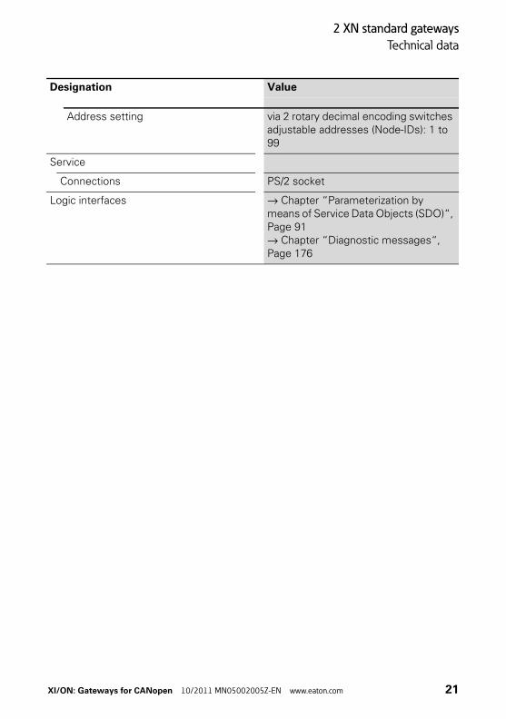
Technical data
Address setting via 2 rotary decimal encoding switches adjustable addresses (Node-IDs): 1 to 99
Service
Connections PS/2 socket
Logic interfaces → Chapter “Parameterization by means of Service Data Objects (SDO)“, Page 91→ Chapter “Diagnostic messages“, Page 176
Designation Value
XI/ON: Gateways for CANopen 10/2011 MN05002005Z-EN www.eaton.com 21
2 XN standard gateways
Connections at XN-GW-CANopen
Connections at XN-GW-CANopen
Field bus termination via SUB-D sockets
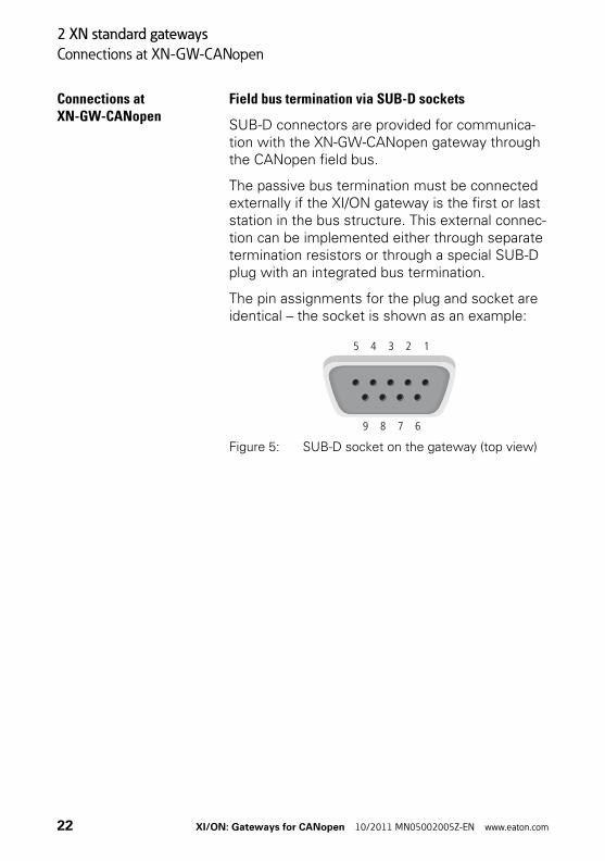
SUB-D connectors are provided for communica-tion with the XN-GW-CANopen gateway through the CANopen field bus.
The passive bus termination must be connected externally if the XI/ON gateway is the first or last station in the bus structure. This external connec-tion can be implemented either through separate termination resistors or through a special SUB-D plug with an integrated bus termination.
The pin assignments for the plug and socket are identical – the socket is shown as an example:
Figure 5: SUB-D socket on the gateway (top view)
5 4 3 2 1
9 678
22 XI/ON: Gateways for CANopen 10/2011 MN05002005Z-EN www.eaton.com

2 XN standard gateways
Connections at XN-GW-CANopen
Table 6: Pin assignment for gateway SUB-D plug/socket
1) The shielding of the field bus is connected through the metal housing of the SUB-D plug and the contact with the mounting rails. → “Attention!”, page 26.
Pin No.
Designation Meaning
1 not used
2 CAN_L inverted data signal (dominant low)
3 CAN_GND ground (optional for the CAN data signals)
4 not used
5 (CAN_SHLD)1)
6 (GND)
7 CAN_H non-inverted data signal (dominant high)
8 not used
9 (CAN_V+)
XI/ON: Gateways for CANopen 10/2011 MN05002005Z-EN www.eaton.com 23
2 XN standard gateways
Connections at XN-GW-CANopen
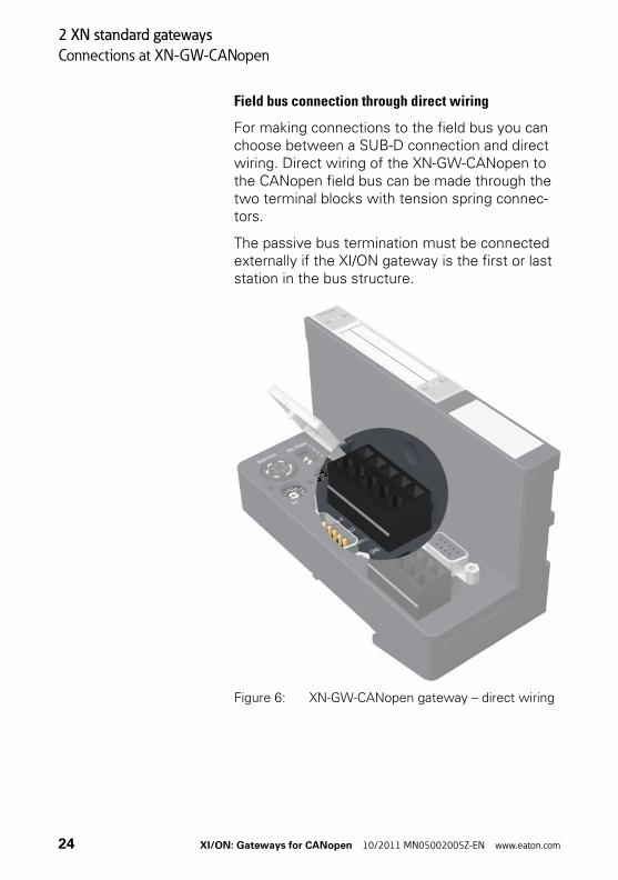
Field bus connection through direct wiring
For making connections to the field bus you can choose between a SUB-D connection and direct wiring. Direct wiring of the XN-GW-CANopen to the CANopen field bus can be made through the two terminal blocks with tension spring connec-tors.
The passive bus termination must be connected externally if the XI/ON gateway is the first or last station in the bus structure.
Figure 6: XN-GW-CANopen gateway – direct wiring
24 XI/ON: Gateways for CANopen 10/2011 MN05002005Z-EN www.eaton.com

2 XN standard gateways
Connections at XN-GW-CANopen
Table 7: List of connecting leads for direct wiring
Figure 7: Shielding connection for an XN-GW-CANopen
Designation Meaning
CAN_L inverted data signal (dominant low)
GND Ground (optional)
SHLD Shielding (→ “Attention!”, page 25)
CAN_H non-inverted data signal (domi-nant high)
Attention!
If the gateway is wired up directly, then the bus connection must be shielded (e.g. with the help of a SCH-1-WINBLOC clamp).
XI/ON: Gateways for CANopen 10/2011 MN05002005Z-EN www.eaton.com 25

2 XN standard gateways
Connections at XN-GW-CANopen
Attention!
No compensating current should flow through the shielding.To achieve this, a reliable system of equipotential bonding must be installed.
→ Equipotential bonding impedance ≦ 1/10 shielding impedance
26 XI/ON: Gateways for CANopen 10/2011 MN05002005Z-EN www.eaton.com

2 XN standard gateways
Connections at XN-GWBR-CANopen
Connections at XN-GWBR-CANopen
Power supply
Gateways with integrated power supply module include additional terminals for connecting the:
• field supply voltage (UL, GNDL) and
• system supply voltage (USYS, GNDSYS)
Figure 8: Terminals for the power supply of the XN-GWBR-CANopen
Gateways without integrated power supply module must be supplied from a neighboring power supply module (XN-BR-24VDC-D)!
XI/ON: Gateways for CANopen 10/2011 MN05002005Z-EN www.eaton.com 27

2 XN standard gateways
Connections at XN-GWBR-CANopen
Field bus connection via open style connector
An open style connector (5-pole) is available for connecting the XN-GWBR-CANopen to the CANopen field bus.
The passive bus termination must be connected externally if the XI/ON gateway is the first or last station in the bus structure.
Table 8: Pin assignment for the DeviceNet socket
Figure 9: Open style connector (female / top)
No. - Color Desig-nation
Meaning
1,2 - red
3,4 - white CAN H non-inverted data signal (dominant high)
5,6 - gray SHIELD Shield braid, not isolated
7,8 - blue CAN L inverted data signal (dominant low)
9,10 - black GND Ground (optional)
28 XI/ON: Gateways for CANopen 10/2011 MN05002005Z-EN www.eaton.com

2 XN standard gateways
Connections at XN-GWBR-CANopen
Figure 10: Open style connector (female / bottom)
Figure 11: Open style connector (male)
CAN L
SHIELD
CAN H
GND
XI/ON: Gateways for CANopen 10/2011 MN05002005Z-EN www.eaton.com 29
2 XN standard gateways
Connections at XN-GWBR-CANopen
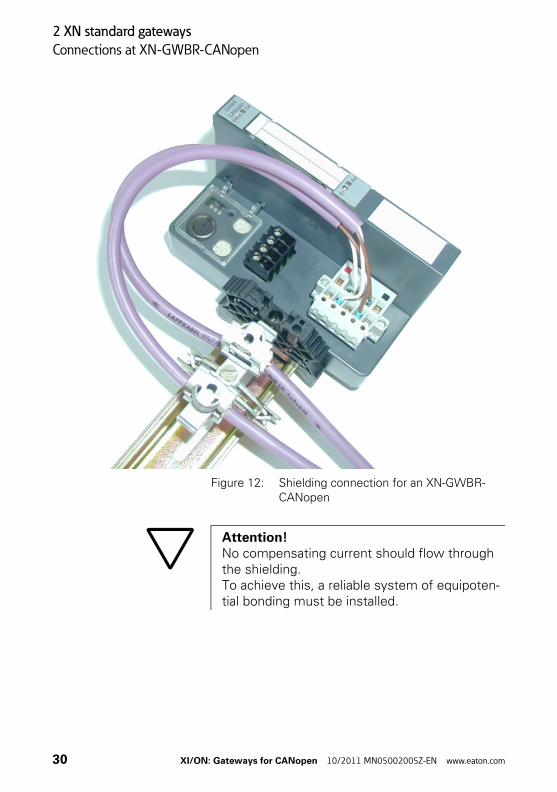
Figure 12: Shielding connection for an XN-GWBR-CANopen
Attention!No compensating current should flow through the shielding.To achieve this, a reliable system of equipoten-tial bonding must be installed.
30 XI/ON: Gateways for CANopen 10/2011 MN05002005Z-EN www.eaton.com

2 XN standard gateways
Service interface connection
Service interface connection
In order to be able to use the service interface of the gateway to connect to a PC with the “I/O assistant” (engineering and diagnostics soft-ware), you will have to use a cable with pin assign-ments that are different from the PS2 standard:
• XI/ON connection cable (XN-PS2-CABLE)
Connection with XI/ON cable
The XI/ON cable is fitted with a PS/2 plug (connec-tion to the socket on the gateway) and a SUB-D socket (connection to the plug on the PC).
Figure 13: PS/2 plug on connecting cable to the gateway (top view)
Figure 14: 9-pole SUB-D socket on connecting cable to PC (top view)
Attention!Standard commercial cables will have to be rewired!
34
6 1
5 2
5 4 3 2 1
9 678
XI/ON: Gateways for CANopen 10/2011 MN05002005Z-EN www.eaton.com 31
2 XN standard gateways
Service interface connection
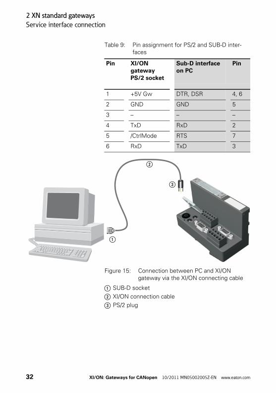
Table 9: Pin assignment for PS/2 and SUB-D inter-faces
Figure 15: Connection between PC and XI/ON gateway via the XI/ON connecting cable
a SUB-D socket
b XI/ON connection cable
c PS/2 plug
Pin XI/ON gateway PS/2 socket
Sub-D interface on PC
Pin
1 +5V Gw DTR, DSR 4, 6
2 GND GND 5
3 – – –
4 TxD RxD 2
5 /CtrlMode RTS 7
6 RxD TxD 3
a
b
c
32 XI/ON: Gateways for CANopen 10/2011 MN05002005Z-EN www.eaton.com

2 XN standard gateways
Setting the bit transfer rate via DIP switches
Setting the bit transfer rate via DIP switches
The XN standard gateway can communicate with other CANopen nodes at the following transfer rates:
The default transfer rate is 125 Kbit/s.The transfer rate can be set by the DIP switches under the cover of the XI/ON gateway.
Figure 16: DIP switches to set the transfer rate
• 10 Kbit/s • 250 Kbit/s
• 20 Kbit/s • 500 Kbit/s
• 50 Kbit/s • 800 Kbit/s
• 125 Kbit/s • 1000 Kbit/s
→ All the nodes in a CANopen network must be set to the same transfer rate.
XI/ON: Gateways for CANopen 10/2011 MN05002005Z-EN www.eaton.com 33
2 XN standard gateways
Setting the bit transfer rate via DIP switches
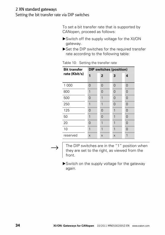
To set a bit transfer rate that is supported by CANopen, proceed as follows:
▶Switch off the supply voltage for the XI/ON gateway.
▶Set the DIP switches for the required transfer rate according to the following table:
Table 10: Setting the transfer rate
▶Switch on the supply voltage for the gateway again.
Bit transfer rate (Kbit/s)
DIP switches (position)
1 2 3 4
1 000 0 0 0 0
800 1 0 0 0
500 0 1 0 0
250 1 1 0 0
125 0 0 1 0
50 1 0 1 0
20 0 1 1 0
10 1 1 1 0
reserved x x x 1
→ The DIP switches are in the “1” position when they are set to the right, as viewed from the front.
34 XI/ON: Gateways for CANopen 10/2011 MN05002005Z-EN www.eaton.com

2 XN standard gateways
Node-ID setting
Node-ID setting A Node-ID is assigned to every XN standard gateway in the CANopen structure.
The setting for the Node-ID of the XN-GW-CANopen in a CANopen structure is made using the two rotary hex encoding switches. The setting for the Node-ID of the XN-GWBR-CANopen in a CANopen structure is made using the two rotary decimal encoding switches. The switches can be found beneath a cover, below the service interface.
The XI/ON gateway can be used as a CANopen node at any position in the bus structure.
Attention!If the XI/ON gateway is used as the first or last node in the bus communication, then a special bus connector with an integrated or switchable termination resistor is absolutely necessary!
XI/ON: Gateways for CANopen 10/2011 MN05002005Z-EN www.eaton.com 35

2 XN standard gateways
Node-ID setting
Figure 17: Rotary hex encoding switch for addressing setting of the XN-GW-CANopen
The rotary encoding switches are marked with H for High (more significant digit) and L for Low (less significant digit).
XN-GW-CANopen:The L switch is used to set L × 160 (L = 0 to F).The H switch is used to set L × 161 (H = 0 to F).
Attention!A maximum of 127 Node-IDs (1 to 127) can be assigned. Each Node-ID can only be assigned once in the complete bus structure.
The Node-ID 000 must not be assigned. It is reserved for telegrams that are directed to all the other bus nodes.
36 XI/ON: Gateways for CANopen 10/2011 MN05002005Z-EN www.eaton.com
2 XN standard gateways
Node-ID setting
XN-GWBR-CANopen:The L switch is used to set L × 100 (L = 0 to 9).The H switch is used to set L × 101 (H = 0 to 9).
→ Chapter “Maximum system configuration of a CANopen bus line“, Page 180.
→ The NODE-ID switch on the XN-GWBR-CANopen can be used to assign Node-IDs from 1 to 99!
→ After setting the Node-ID, the protective cover over the switches must be closed again.
→ XI/ON does not support the assignment of Node-IDs across the bus network.
XI/ON: Gateways for CANopen 10/2011 MN05002005Z-EN www.eaton.com 37

2 XN standard gateways
Acceptance of the XI/ON configuration
Acceptance of the XI/ON configuration
When a new configuration of the XI/ON station is made or the existing station structure (“Module list”) is altered, the current configuration must be accepted in the CANopen image of the XI/ON gateway. This is done using the configuration button located between the two rotary encoding switches.
Figure 18: Configuration button to accept the XI/ON configuration (“Module list”)
→ The green IOs LED indicates that the current XI/ON configuration matches the stored refer-ence module list.
38 XI/ON: Gateways for CANopen 10/2011 MN05002005Z-EN www.eaton.com

2 XN standard gateways
Acceptance of the XI/ON configuration
Pressing the button with a pointed object for at least 2 seconds retentively stores the current station configuration. A hardware reset will then be carried out automatically. With this reset, all the CANopen parameters will be restored to their default values, if the newly saved configuration is different to the old one.
The actuation of the button is indicated by a rapid (4 Hz) green flashing of the “IOs” LED. After 2 seconds, the LED changes to yellow flashing at 4 Hz, thus indicating that the station configuration is being saved. When the storage procedure is completed, the LED changes to a continuous green light.
Attention!When the XI/ON configuration is saved, all the CANopen objects must be parameterized again, if their parameter values differ from the default values. The complete parameterization of the station must then be reloaded into the XI/ON station.
XI/ON: Gateways for CANopen 10/2011 MN05002005Z-EN www.eaton.com 39

2 XN standard gateways
Diagnostics LED indications
Diagnostics LED indications
Each XI/ON gateway is fitted with the following LEDs for status indication:
• 2 LEDs for module bus communication (module bus LEDs): GW and IOs
• 2 LEDs CANopen communication (field bus LEDs): Err and Bus
The LED diagnostics shown below apply to both gateway versions:
• XN-GW-CANopen
• XN-GWBR-CANopen
An additional diagnostics indication is shown for the XN-GWBR-CANopen via the LED GW.
Table 11: LEDs
LED Status Meaning Remedy
GW Green 5 V DC operating voltage present firmware active; gateway ready for operation and transfer
–
green flashing, 4 Hz
Firmware active, gateway hardware faulty
Replace the gateway.
GW& IOs
GW: green flashing, 1 HzIOs: red
Firmware not active Reload firmware!
Additional diagnostics indication for XN-GWBR-CANopen
GW green flashing, 1 Hz
USYS: Under-voltage or over-voltageUL: Undervoltage
Check that the supply voltage is within the permissible range. → Chapter “Technical data for XN-GWBR-CANopen“, Page 20.
CANopen
GW IOs
40 XI/ON: Gateways for CANopen 10/2011 MN05002005Z-EN www.eaton.com

2 XN standard gateways
Diagnostics LED indications
IOs green Configured arrange-ment of the module stations matches the actual configu-ration; communica-tion active.
–
green flashing, 1 Hz
Station is in Force Mode of I/Oassis-tant.
Deactivate Force Mode of I/Oassistant
red and GW LED is OFF
Controller is not for operation, or the USYS level is not within the required limits.
Test the bus refreshing module on the right of the gateway and its wiring. If the applied supply voltage is correct, please contact your Eaton partner.
red Module bus not ready for operation
Check that the individual XI/ON modules are properly installed
red flashing, 1 Hz
There is a non-adaptable alteration of the actual arrangement of the module bus stations
Compare the configuration of your XI/ON station with the actual arrangement.Test the implementation of your XI/ON station for faulty or incor-rectly inserted electronics modules.
red/green flashing, 1 Hz
There is an adapt-able alteration of the actual arrange-ment of the module bus stations
Check the XI/ON station for missing or new, unconfigured modules.
red flashing, 4 Hz
No communication via the module bus
Check that the rules for the application of power supply modules have been observed.
LED Status Meaning Remedy
XI/ON: Gateways for CANopen 10/2011 MN05002005Z-EN www.eaton.com 41

2 XN standard gateways
Diagnostics LED indications
Err OFF No errors in communication between the XI/ON-CANopen gateway and other CANopen nodes
–
red Faulty or inter-rupted communica-tion between the XI/ON-CANopen gateway and other CANopen nodesPossible causes:• CAN-BusOff• Heartbeat error• Guarding error• Transmit timeout
• Check that the field bus ends with a termination resistor if the XI/ON-CANopen gateway is the last node in the bus topology.
• Check the seating of the CANopen bus connector (or the joints in the case of direct wiring). All connections must be correct and properly seated.
• Check the CANopen cable for possible damage, and for correct connections.
• Check that the correct bit rate has been set.
• Check that the NMT master is still functioning properly.
LED Status Meaning Remedy
Err Bus
42 XI/ON: Gateways for CANopen 10/2011 MN05002005Z-EN www.eaton.com

2 XN standard gateways
Diagnostics LED indications
Bus OFF Field bus not oper-ating
• Wait until the firmware down-load is finished.
• If the download is finished: hardware error; replace the gateway.
red NMT slave state of the XI/ON-CANopen gateway is “Stopped”
–
orange NMT slave state of the XI/ON-CANopen gateway is “Pre-Opera-tional”
–
green NMT slave state of the XI/ON-CANopen gateway is “Operational”
–
ERR &Bus
red flashing alternately, 4 Hz
Invalid Node-ID has been set
Set the correct Node-ID with the rotary hex or decimal encoding switches.
LED Status Meaning Remedy
XI/ON: Gateways for CANopen 10/2011 MN05002005Z-EN www.eaton.com 43

2 XN standard gateways
Diagnostics LED indications
44 XI/ON: Gateways for CANopen 10/2011 MN05002005Z-EN www.eaton.com

3 XNE ECO gateway
Gateway XNE-GWBR-CANopen
3 XNE ECO gateway
Gateway XNE-GWBR-CANopen
Figure 19: XNE-GWBR-CANopen
a Type designation
b LEDs for XI/ON station
c Service interface
d DIP switch for the Node-ID
e DIP switch for the bit rate
f DIP switch for the terminating resistor
g LEDs for CANopen
h Push-in tension clamp terminals for field supply
i Push-in tension clamp terminals for system supply
j Push-in tension clamp terminals for CANopen
XNE-GWBR-CANOPEN a
bc
f
d
e
g
h
i
j
XI/ON: Gateways for CANopen 10/2011 MN05002005Z-EN www.eaton.com 45

3 XNE ECO gateway
Technical data
Technical data Structure of a XNE ECO gateway
Figure 20: Structure of a XNE-GWBR-CANopen
Technical data for the XNE station
Table 12: Technical data for the XNE station
FIeldbus(external)
Serviceinterface
External memory Module bus(internal)
Controller
Attention!The auxiliary supply must meet the require-ments for SELV (= Safety Extra Low Voltage) according to IEC 60364-4-41.
Designation Value
Maximum system extension 62 modules (XN, XNE) in slice design or max. length of station: 1 m
Supply voltage/ auxiliary voltage
Field supply
UL nominal value (range) 24 V DC (18 to 30 V DC)
IL max. field current 10 A
Insulation voltage (UL to USYS / UL to field bus / UL to FE)
500 Vrms
System supply
USYS nominal value (range) 24 V DC (18 to 30 V DC)
46 XI/ON: Gateways for CANopen 10/2011 MN05002005Z-EN www.eaton.com

3 XNE ECO gateway
Technical data
ISYS (at maximum station extension→ Chapter “Maximum station extension“, Page 64)
max. 500 mA
IMB (supply to the moudle bus participants) 700 mA
Insulation voltage (USYS to UL / USYS to field bus / USYS to FE)
500 Vrms
Residual ripple according to IEC/EN 61131-2
Voltage anomalies according to IEC/EN 61131-2
Connection technology Push-in tension clamp terminals
Physical interfaces
Field bus
Protocol CANopen
Transmission rate 20 kBit/s to 1 Mbit/s
Insulation voltage (field bus to USYS / field bus to UL / field bus to FE)
500 Vrms
Field bus connection Push-in tension clamp terminals
Address setting Via DIP-switches adjustable addresses (Node-IDs): 1 to 63
Service interface
Connection RS232 at PS2/ mini DIN female connector
Ambient conditions
Ambient temperature
tAmbient 0 to +55 °C / 32 to 131 °F
tStore -25 to +85 °C / 13 to 185 °F
Relative humidity according to IEC/EN 60068-2-30
5 to 95 % (indoor), Level RH-2, no condensation (storage at 45 °C, no function test)
Climatic tests according to IEC/EN 61131-2
Designation Value
XI/ON: Gateways for CANopen 10/2011 MN05002005Z-EN www.eaton.com 47

3 XNE ECO gateway
Technical data
Resistance to vibration
10 to 57 Hz, constant amplitude 0.075 mm / 0.003 inch, 1g
Yes
57 to 150 Hz, constant acceleration 1 g Yes
Mode of vibration Frequency sweeps with a change in speed of 1 Octave/min
Period of oscillation 20 frequency sweeps per axis of coordinate
Shock resistant according to IEC/EN 60068-2-27
18 shocks, sinusoidal half-wave 15 g peak value/11 ms, in each case in ± direction per space coordinate
Resistance to repetitive shock according to IEC/EN 60068-2-29
1 000 shocks, half-sinus 25 g peak value/6 ms, in each case in ± direction per space coordinate
Drop and topple
Height of fall (weight < 10 kg) 1.0 m
Height of fall (weight 10 to 40 kg) 0.5 m
Test runs 7
Device with packaging, electrically tested printed-circuit board.
Yes
Electromagnetic compatibility (EMC) according to IEC/EN 61000-6-2 (Industry)
Static electricity according to IEC/EN 61000-4-2
Discharge through air (direct) 8 kV
Relay discharge (indirect) 4 kV
Electromagnetic HF fields according to IEC/EN 61000-4-3
10 V/m
Conducted interferences induced by HF fields according to IEC/EN 61000-4-6
10 V
Designation Value
48 XI/ON: Gateways for CANopen 10/2011 MN05002005Z-EN www.eaton.com

3 XNE ECO gateway
Technical data
1) This device can cause radio disturbances in residen-tial areas. Additional measures to suppress the disturbance are necessary.
Fast transients (Burst) according to IEC/EN 61000-4-4
Emitted interference according to IEC/EN 61000-6-4 (Industry)
according to IEC/CISPR 11 / EN 55011 Class A 1)
Designation Value
XI/ON: Gateways for CANopen 10/2011 MN05002005Z-EN www.eaton.com 49
3 XNE ECO gateway
Technical data
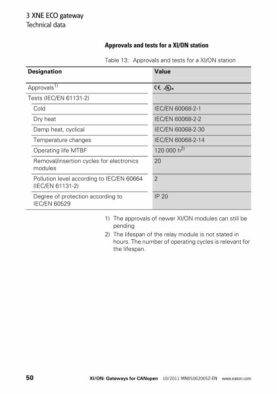
Approvals and tests for a XI/ON station
Table 13: Approvals and tests for a XI/ON station
1) The approvals of newer XI/ON modules can still be pending
2) The lifespan of the relay module is not stated in hours. The number of operating cycles is relevant for the lifespan.
Designation Value
Approvals1) ,
Tests (IEC/EN 61131-2)
Cold IEC/EN 60068-2-1
Dry heat IEC/EN 60068-2-2
Damp heat, cyclical IEC/EN 60068-2-30
Temperature changes IEC/EN 60068-2-14
Operating life MTBF 120 000 h2)
Removal/insertion cycles for electronics modules
20
Pollution level according to IEC/EN 60664 (IEC/EN 61131-2)
2
Degree of protection according to IEC/EN 60529
IP 20
50 XI/ON: Gateways for CANopen 10/2011 MN05002005Z-EN www.eaton.com

3 XNE ECO gateway
Technical data
Technical Data for the Push-in tensionclamp terminals
Table 14: Technical data for the Push-in tension clamp terminals
Designation Value
Measurement data according to VDE 0611 Part 1/8.92 / IEC/EN 60947-7-1
Protection class IP20
Insulation stripping length 8.0 to 9.0 mm / 0.32 to 0.36 inch
Max. wire range 0.14 to 1.5 mm2 / 0.0002 to 0.0023 inch2 / AWG 24 to AWG 16
Crimpable wire
“e” solid core H 07V-U 0.25 to 1.5 mm2 / 0.0004 to 0.0023 inch2
“f” flexible core H 07V-K 0.25 to 1.5 mm2 / 0.0004 to 0.0023 inch2
“f” with ferrules without plastic collar according to DIN 46228-1 (ferrules crimped gas-tight)
0.25 to 1.5 mm2 / 0.0004 to 0.0023 inch2
“f” with ferrules with plastic collar according to DIN 46228-1 (ferrules crimped gas-tight)
0.25 to 0.75 mm2 / 0.0004 to 0.0012 inch2
Test finger according to IEC/EN 60947-1 A1
XI/ON: Gateways for CANopen 10/2011 MN05002005Z-EN www.eaton.com 51
3 XNE ECO gateway
Connections at XNE-GWBR-CANopen
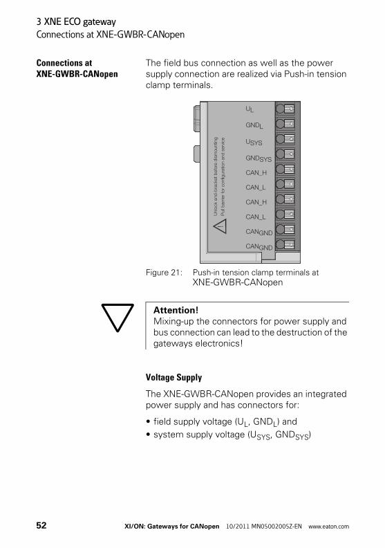
Connections at XNE-GWBR-CANopen
The field bus connection as well as the power supply connection are realized via Push-in tension clamp terminals.
Figure 21: Push-in tension clamp terminals at XNE-GWBR-CANopen
Voltage Supply
The XNE-GWBR-CANopen provides an integrated power supply and has connectors for:
• field supply voltage (UL, GNDL) and
• system supply voltage (USYS, GNDSYS)
Attention!Mixing-up the connectors for power supply and bus connection can lead to the destruction of the gateways electronics!
52 XI/ON: Gateways for CANopen 10/2011 MN05002005Z-EN www.eaton.com
3 XNE ECO gateway
Connections at XNE-GWBR-CANopen
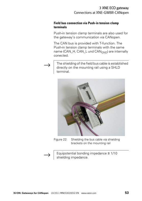
Field bus connection via Push-in tension clamp terminals
Push-in tension clamp terminals are also used for the gateway’s communication via CANopen.
The CAN bus is provided with T-function. The Push-in tension clamp terminals with the same name (CAN_H, CAN_L und CANGND) are internally conected.
Figure 22: Shielding the bus cable via shielding brackets on the mounting rail
→ The shielding of the field bus cable is established directly on the mounting rail using a SHLD terminal.
→ Equipotential bonding impedance ≦ 1/10 shielding impedance.
XI/ON: Gateways for CANopen 10/2011 MN05002005Z-EN www.eaton.com 53
3 XNE ECO gateway
Service interface connection
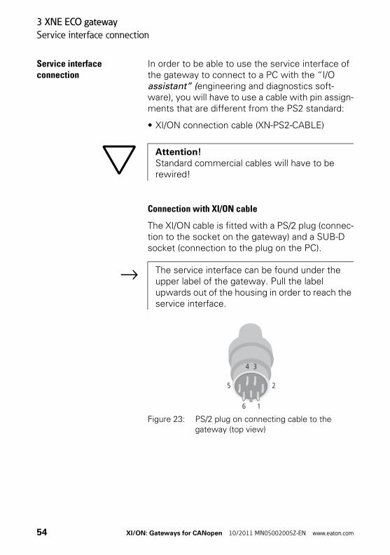
Service interface connection
In order to be able to use the service interface of the gateway to connect to a PC with the “I/O assistant” (engineering and diagnostics soft-ware), you will have to use a cable with pin assign-ments that are different from the PS2 standard:
• XI/ON connection cable (XN-PS2-CABLE)
Connection with XI/ON cable
The XI/ON cable is fitted with a PS/2 plug (connec-tion to the socket on the gateway) and a SUB-D socket (connection to the plug on the PC).
Figure 23: PS/2 plug on connecting cable to the gateway (top view)
Attention!Standard commercial cables will have to be rewired!
→ The service interface can be found under the upper label of the gateway. Pull the label upwards out of the housing in order to reach the service interface.
34
6 1
5 2
54 XI/ON: Gateways for CANopen 10/2011 MN05002005Z-EN www.eaton.com
3 XNE ECO gateway
Service interface connection
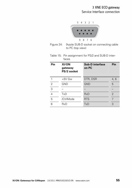
Figure 24: 9-pole SUB-D socket on connecting cable to PC (top view)
Table 15: Pin assignment for PS/2 and SUB-D inter-faces
5 4 3 2 1
9 678
Pin XI/ON gateway PS/2 socket
Sub-D interface on PC
Pin
1 +5V Gw DTR, DSR 4, 6
2 GND GND 5
3 – – –
4 TxD RxD 2
5 /CtrlMode RTS 7
6 RxD TxD 3
XI/ON: Gateways for CANopen 10/2011 MN05002005Z-EN www.eaton.com 55

3 XNE ECO gateway
Setting the Node-ID
Setting the Node-ID The setting of the Node-ID for the XNE ECO gateway for CANopen is done via the DIP switches at the gateway.
These DIP switches can be found under the gateway’s upper label.
Figure 25: DIP-switches on the gateway
The gateway’s bus address results from the addi-tion of the valences (20 to 25) of the switched DIP-switches (position = 1).
Default setting:0×01H = ADR 01
→ Pull the label upwards out of the housing in order to reach the DIP-switches.
Attention!The Node-ID of an XNE ECO gateway is limited to values of 1 to 63. Other nodes at the CANopen bus can use Node-IDs up to 127. Each Node-ID can only be assigned once in the entire CANopen bus structure.
56 XI/ON: Gateways for CANopen 10/2011 MN05002005Z-EN www.eaton.com

3 XNE ECO gateway
Setting the Node-ID
Example: Bus address 38 = 0×26 = 100110
Figure 26: Bus address 38
The internal module bus does not require any addressing.
XI/ON: Gateways for CANopen 10/2011 MN05002005Z-EN www.eaton.com 57

3 XNE ECO gateway
Setting the bit rate
Setting the bit rate The gateway XNE-GWBR-CANopen offers 3 DIP switches for setting the bit rate (BR).
Figure 27: DIP switches for setting the bit rate
Table 16: Setting the bit rate
DIP switch no.
Bit rate
reserved
20 kBit/s
50 kBit/s
125 kBit/s
250 kBit/s
500 kBit/s
800 kBit/s
1 MBit/s
20 1 0 1 0 1 0 1 0
21 1 1 0 0 1 1 0 0
22 1 1 1 1 0 0 0 0
58 XI/ON: Gateways for CANopen 10/2011 MN05002005Z-EN www.eaton.com

3 XNE ECO gateway
Activating the bus terminating resistor
Activating the bus terminating resistor
If the XNE ECO gateway is used as the first or the last station in the bus communication, the field bus line has to be terminated using a terminating resistor.
The XNE-GWBR-CANopen allows the activation of the resistors RT using the last DIP-switch.
Figure 28: Bus terminating resistor RT
Bus terminating resistor switched off:
Bus terminating resistor switched on:
XI/ON: Gateways for CANopen 10/2011 MN05002005Z-EN www.eaton.com 59

3 XNE ECO gateway
Acceptance of the XI/ON station configuration
Acceptance of the XI/ON station configuration
When making a new configuration of the XI/ON station or an alteration of the existing station struc-ture (“module list”), the current configuration must be accepted in the CANopen mirror of the XI/ON gateway.
The configuration acceptance at this device is done via the DIP switches set to address 0.
Please proceed as follows:
▶Set the DIP switches at the gateway to a Node-ID ≠ “0”.
▶Switch on the system supply USYS and the field supply UL.
▶Set the Node-ID to “0”. → The device stores the station’s configuration. This is indicated by the flashing of the “IOs” LED.→ After the storage procedure, the “IOs” LED shortly flashes orange and than stops flashing. → The LEDs “Err” and “Bus” flash alternately red with 4 Hz due to the invalid Node-ID “0” which is still set at the gateway.
▶De-energize the gateway and set a Node-ID ¹ “0” at the gateway. → After power-on, the “IOs” LED changes to green after approximately 2 seconds.
→ The green “IOs” LED indicates that the current XI/ON configuration matches the stored refer-ence module list.
Attention!If the new configuration stored to the gateway does not match the old configuration, all CANopen-parameters are set to their default values. Therefore it is necessary, to reload the whole station parameterization.
60 XI/ON: Gateways for CANopen 10/2011 MN05002005Z-EN www.eaton.com

3 XNE ECO gateway
Diagnostic messages via LEDs
Diagnostic messages via LEDs
Every XI/ON gateway displays the following statuses via LEDs:
• 2 LEDs for module bus communication (module bus LEDs): GW and IOs
• 2 LEDs for CANopen communication (field bus LEDs): ERR and Bus
Table 17: LED displays
LED Status Meaning Remedy
GW OFF CPU not supplied. Check the wiring at the gateway or at the Bus refreshing module.
Green 5 V DC operating voltage is present; firmware is active; gateway is ready for operation and transfer
–
green flashing, 1 Hz
Undervoltage at USYS or UL
Check that the supply voltage is within the permissible range.
GW: green flashing, 1 HzIOs: red
Firmware not active Reload the firmware!
Green flashing,4 Hz
Firmware active, gateway hardware is defect
Replace the gateway.
XI/ON: Gateways for CANopen 10/2011 MN05002005Z-EN www.eaton.com 61

3 XNE ECO gateway
Diagnostic messages via LEDs
IOs OFF CPU not supplied. Check the voltage supply.
Green Module bus is running, the configured module bus station corresponds to the physically connected station, communication is active.
–
Green flashing1 Hz
Station is in the I/Oassistant Force Mode.
Deactivate the I/Oassistant Force Mode.
Red and LED “GW” off
Controller is not ready, USYS level is not within the required range.
Check the wiring for USYS at the gateway.
Red Module bus not ready-to-operate
Check the correct mounting of the single XI/ON-modules
Red flashing,1 Hz
Non-adaptable modification of the physically connected station.
Compare the planned XI/ON station with the physical station.Check the physical station for defective or incorrectly fitted electronics modules.
Red flashing, 4 Hz
No module bus communication
Check the station configuration and the voltage supply at the gateway and at the supply modules.
Red/green flashing, 1 Hz
Adaptable modifica-tion of the physi-cally connected station;data transfer possible
Check the physical station for pulled or new but not planned modules.
LED Status Meaning Remedy
62 XI/ON: Gateways for CANopen 10/2011 MN05002005Z-EN www.eaton.com

3 XNE ECO gateway
Diagnostic messages via LEDs
ERR Off No errors in communication between the XI/ON-CANopen gateway and other CANopen nodes
–
Red Faulty or inter-rupted communica-tion between XI/ON-CANopen gateway and other CANopen.Possible causes:• CAN-BusOff• Heartbeat error• Guarding error• Transmit timeout
Check that the field bus ends with a termination resistor, if the XI/ON-CANopen gateway is the last node in the bus topology.Check the seating of the CANopen bus connector (or the joints in the case of direct wiring). All connections must be correct and properly seated.Check the CANopen cable for possible damage, and for correct connections.Check that the correct bit rate has been set.Check that the NMT-master is still functioning properly.
BUS green NMT-slave state of the XI/ON-CANopen gateway is “Operational”; communication active.
–
red NMT-slave state of the XI/ON-CANopen gateway is “Stopped”
The state can be passed by the command “Reset-Node” and “Start-Node”
orange NMT-slave state of the XI/ON-CANopen gateway is “Pre-Opera-tional”
“Start-Node”-command from NMT- Master necessary, to get into state “Operational”.
ERR &BUS
red flashing alternately, 4 Hz
Invalid Node-ID has been set
Set the correct Node-ID with the DIP switches (1 to 63).
LED Status Meaning Remedy
XI/ON: Gateways for CANopen 10/2011 MN05002005Z-EN www.eaton.com 63
3 XNE ECO gateway
Maximum station extension
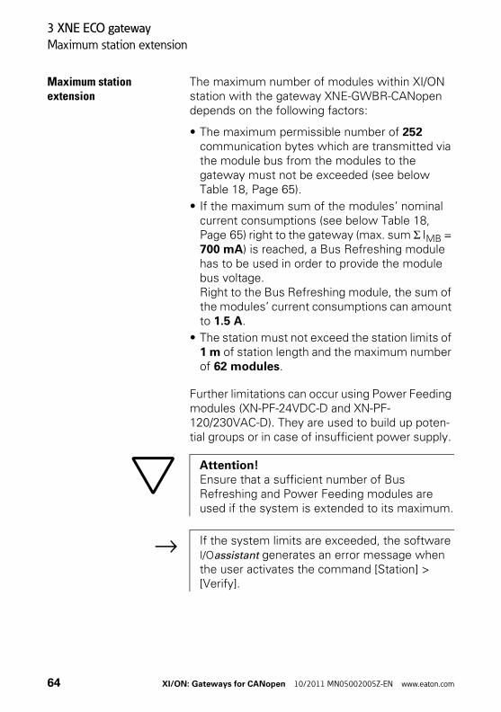
Maximum station extension
The maximum number of modules within XI/ON station with the gateway XNE-GWBR-CANopen depends on the following factors:
• The maximum permissible number of 252 communication bytes which are transmitted via the module bus from the modules to the gateway must not be exceeded (see below Table 18, Page 65).
• If the maximum sum of the modules’ nominal current consumptions (see below Table 18, Page 65) right to the gateway (max. sum Σ IMB = 700 mA) is reached, a Bus Refreshing module has to be used in order to provide the module bus voltage. Right to the Bus Refreshing module, the sum of the modules’ current consumptions can amount to 1.5 A.
• The station must not exceed the station limits of 1 m of station length and the maximum number of 62 modules.
Further limitations can occur using Power Feeding modules (XN-PF-24VDC-D and XN-PF-120/230VAC-D). They are used to build up poten-tial groups or in case of insufficient power supply.
Attention!Ensure that a sufficient number of Bus Refreshing and Power Feeding modules are used if the system is extended to its maximum.
→ If the system limits are exceeded, the software I/Oassistant generates an error message when the user activates the command [Station] > [Verify].
64 XI/ON: Gateways for CANopen 10/2011 MN05002005Z-EN www.eaton.com

3 XNE ECO gateway
Maximum station extension
For the calculation of the maximum system exten-sion, the following table contains an overview about communication bytes as well as about the modules’ nominal current consumptions.
Table 18: Communication bytes and nominal current consumptions of the XI/ON modules
Module Number of communication bytes
Nominal current consumption from module bus IMB
XN-BR-24VDC-D 2 -
XN-PF-24VDC-D 2 ≦ 28 mA
XN-PF-120/230VAC-D 2 ≦ 25 mA
XN-2DI-24VDC-P 1 ≦ 28 mA
XN-2DI-24VDC-N 1 ≦ 28 mA
XN-2DI-120/230VAC 1 ≦ 28 mA
XN-4DI-24VDC-P 1 ≦ 29 mA
XN-4DI-24VDC-N 1 ≦ 28 mA
XN-16DI-24VDC-P 2 ≦ 45 mA
XN-32DI-24VDC-P 4 ≦ 30 mA
XNE-8DI-24VDC-P 1 ≦ 15 mA
XNE-16DI-24VDC-P 2 ≦ 15 mA
XN-1AI-I(0/4...20MA) 3 ≦ 41 mA
XN-2AI-I(0/4...20MA) 5 ≦ 35 mA
XN-1AI-U(-10/0...+10VDC) 3 ≦ 41 mA
XN-2AI-U(-10/0...+10VDC) 5 ≦ 35 mA
XN-2AI-PT/NI-2/3 5 ≦ 45 mA
XN-2AI-THERMO-PI 5 ≦ 45 mA
XN-4AI-U/I 9 ≦ 20 mA
XNE-8AI-U/I-4PT/NI 9 ≦ 30 mA
XN-2DO-24VDC-0.5A-P 2 ≦ 32 mA
XN-2DO-24VDC-0.5A-N 2 ≦ 32 mA
XN-2DO-24VDC-2A-P 2 ≦ 33 mA
XI/ON: Gateways for CANopen 10/2011 MN05002005Z-EN www.eaton.com 65

3 XNE ECO gateway
Maximum station extension
XN-2DO-120/230VAC-0.5A 2 ≦ 35 mA
XN-4DO-24VDC-0.5A-P 2 ≦ 30 mA
XN-16DO-24VDC-0.5A-P 3 ≦ 120 mA
XN-32DO-24VDC-0.5A-P 5 ≦ 30 mA
XNE-8DO-24VDC-0.5A-P 2 ≦ 15 mA
XNE-16DO-24VDC-0.5A-P 2 ≦ 25 mA
XN-1AO-I(0/4...20MA) 4 ≦ 39 mA
XN-2AO-I(0/4...20MA) 7 ≦ 40 mA
XN-2AO-U(-10/0...+10VDC) 7 ≦ 43 mA
XNE-4AO-U/I 9 ≦ 40 mA
XN-2DO-R-NC 1 ≦ 28 mA
XN-2DO-R-NO 1 ≦ 28 mA
XN-2DO-R-CO 1 ≦ 28 mA
XN-1CNT-24VDC 9 ≦ 40 mA
XNE-2CNT-2PWM 9 ≦ 30 mA
XN-1RS232 9 ≦ 140 mA
XN-1RS485/422 9 ≦ 60 mA
XN-1SSI 9 ≦ 50 mA
XNE-1SWIRE 9 ≦ 60 mA
Module Number of communication bytes
Nominal current consumption from module bus IMB
66 XI/ON: Gateways for CANopen 10/2011 MN05002005Z-EN www.eaton.com

4 Communication in CANopen
General
4 Communication in CANopen
General CANopen is an open, non-proprietary network protocol. It consists of a profile family, based on a communication profile and several device profiles. The CANopen communication profile is standard-ized as CiA DS-301 (Application Layer and Communication Profile).
The CANopen device profile for I/O modules has been published as CiA DS-401 (Device Profile for I/O Modules).
CANopen is based on the following standards:
• • ISO 11 898 (Physical and Data Link Layer)Layers 1 and 2 of the ISO/OSI communication model
• CiA DS-301 (Application Layer and Communica-tion Profile)CANopen communication profile
• • CiA DS-302 (Framework for Programmable CANopen Devices)CANopen Network Management NMT
• CiA DS-401 (Device Profile for I/O modules)
• CiA DS-406 (Device Profile for Encoders)CANopen device profile for counter modules
• CiA DS-102 (CAN Physical Layer for Industrial Applications)General industrial application in the field sector (connectors and bit rates) on the basis of ISO 11898
XI/ON: Gateways for CANopen 10/2011 MN05002005Z-EN www.eaton.com 67

4 Communication in CANopen
Communication
Communication The lower layers of CANopen are defined according to the ISO-OSI model in the ISO 11898 standard.
Communication between the individual nodes is made by transmitting “Telegrams”.
6 different types of telegram messages (Commu-nication Objects) are defined for CANopen:
• Network Management Messages (NMT)
• Service Data Objects (SDO)
• Process Data Objects (PDO)
• Synchronisation Objects (Sync)
• Emergency Objects (Emcy)
• Time Stamp Objects (Time)
In addition, there are a number of transmis-sion/transfer settings (Transmission Types) for process data. The telegrams moving through the network have their priorities marked through their identifiers (a low ID = high priority). An arbitration procedure ensures fast delivery of important tele-grams if the network is heavily loaded.
68 XI/ON: Gateways for CANopen 10/2011 MN05002005Z-EN www.eaton.com

4 Communication in CANopen
Communication
Types of telegram messages(Communication Objects)
Network Management Messages (NMTs)Network management messages are used in the network to control the nodes and their operating states. The network management objects include boot-up message, heartbeat protocol and NMT message.
Service Data Objects (SDOs) Service data objects (SDOs) are used for transfer-ring low-priority acyclic data. SDOs are typically used for the configuration of CANopen nodes, to set device parameters, and to download programs. SDOs can be used to transfer data of any length, by using the technique known as “segmented transfer”.
Process Data Objects (PDOs)Process data objects (PDOs) are used for the fast transfer of high-priority data. PDOs are uncon-firmed services, so they do not carry a protocol overhead. They are therefore a method of fast and flexible data transfer from one node to any number of other nodes. PDOs can contain a maximum of 8 data bytes, and can be specifically configured and assembled by the user to meet specific require-ments.
XI/ON: Gateways for CANopen 10/2011 MN05002005Z-EN www.eaton.com 69

4 Communication in CANopen
Communication
PDO transmissions:
• Event- or timer-driven: An event (specified in the device profile) triggers message transmission. An elapsed timer addi-tionally triggers the periodically transmitting of a PDO message.
• Remotely requested: Another device may initiate the transmission of an asynchronous PDO by sending a remote transmission request (remote frame).
• Synchronous transmission: In order to initiate simultaneous sampling of input values of all nodes, a periodically trans-mitted Sync message is required. Synchronous transmission of PDOs takes place in cyclic and acyclic transmission mode. Cyclic transmission means that the node waits for the Sync message, after which it sends its measured values. Acyclically transmitted synchronous PDOs are triggered by a defined application-specific event.
Synchronisation Objects (Sync)The Sync Object is broadcast periodically by the Sync Producer. The time period between Sync messages is defined by the Communication Cycle Period, which may be reset by a configuration tool to the application devices during the boot-up process. There can be a time jitter in transmission by the Sync Producer due to some other objects with higher prior identifiers or by one frame being transmitted just before the Sync message. The Sync message is mapped to a single CAN frame with the identifier 128.
70 XI/ON: Gateways for CANopen 10/2011 MN05002005Z-EN www.eaton.com
4 Communication in CANopen
XI/ON and CANopen
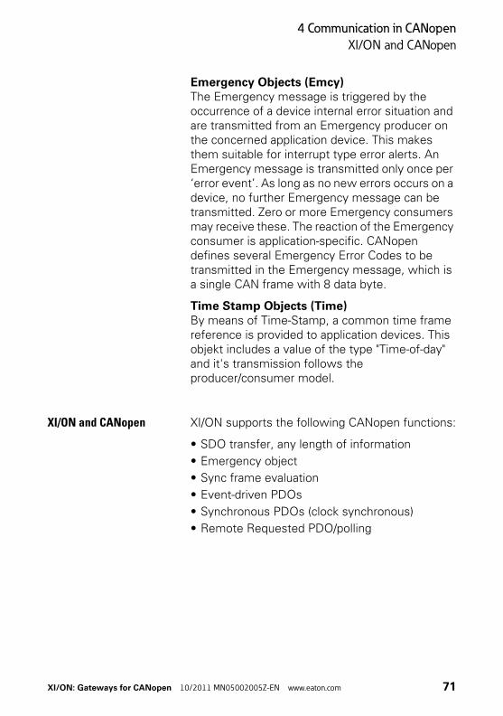
Emergency Objects (Emcy)The Emergency message is triggered by the occurrence of a device internal error situation and are transmitted from an Emergency producer on the concerned application device. This makes them suitable for interrupt type error alerts. An Emergency message is transmitted only once per ‘error event’. As long as no new errors occurs on a device, no further Emergency message can be transmitted. Zero or more Emergency consumers may receive these. The reaction of the Emergency consumer is application-specific. CANopen defines several Emergency Error Codes to be transmitted in the Emergency message, which is a single CAN frame with 8 data byte.
Time Stamp Objects (Time)By means of Time-Stamp, a common time frame reference is provided to application devices. This objekt includes a value of the type "Time-of-day" and it's transmission follows the producer/consumer model.
XI/ON and CANopen XI/ON supports the following CANopen functions:
• SDO transfer, any length of information
• Emergency object
• Sync frame evaluation
• Event-driven PDOs
• Synchronous PDOs (clock synchronous)
• Remote Requested PDO/polling
XI/ON: Gateways for CANopen 10/2011 MN05002005Z-EN www.eaton.com 71

4 Communication in CANopen
Electronic data sheet – EDS file
Electronic data sheet – EDS file
The XI/ON gateway is embedded in the CANopen structure with the help of a standardized EDS file (Electronic Data Sheet).
The EDS file lists all the Objects with their corre-sponding Sub-indices and the matching entries.
Figure 29: Header of an EDS file for XI/ON
The latest version of a particular EDS file can be obtained from our website(www.eaton-automation.com),under “DOWNLOADS”.
72 XI/ON: Gateways for CANopen 10/2011 MN05002005Z-EN www.eaton.com

4 Communication in CANopen
Setting up communication
Setting up communication Minimum Boot-up
XI/ON supports the Minimum Boot-up function described in CiA DS-301.
Table 19: Meaning of the abbreviations
Booting with the Minimum Boot-up function is the typical application option for CANopen, and runs according to the following state diagram:
Figure 30: Boot procedure with Minimum Boot-up
Abbrevia-tion
Meaning Explanation
cs NMT command spec-ifier
A designation label for the required service
Node-ID Node Identifier Identifier for the node; an identification byte that is set through the encoding switches for the CAN node.
a
c
d
b
e
f
g
h
i
j
k
l
m
n
Power on oder Hardware Reset
Zustand Pre-Operational
Zustand Initialisation
Zustand Operational
Zustand Stopped
XI/ON: Gateways for CANopen 10/2011 MN05002005Z-EN www.eaton.com 73
4 Communication in CANopen
Setting up communication
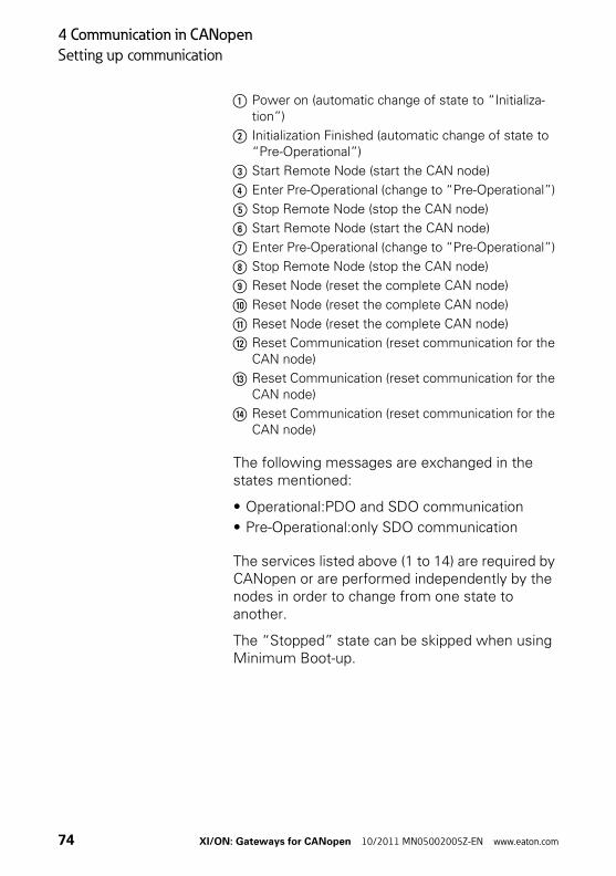
a Power on (automatic change of state to “Initializa-tion”)
b Initialization Finished (automatic change of state to “Pre-Operational”)
c Start Remote Node (start the CAN node)
d Enter Pre-Operational (change to “Pre-Operational”)
e Stop Remote Node (stop the CAN node)
f Start Remote Node (start the CAN node)
g Enter Pre-Operational (change to “Pre-Operational”)
h Stop Remote Node (stop the CAN node)
i Reset Node (reset the complete CAN node)
j Reset Node (reset the complete CAN node)
k Reset Node (reset the complete CAN node)
l Reset Communication (reset communication for the CAN node)
m Reset Communication (reset communication for the CAN node)
n Reset Communication (reset communication for the CAN node)
The following messages are exchanged in the states mentioned:
• Operational:PDO and SDO communication
• Pre-Operational:only SDO communication
The services listed above (1 to 14) are required by CANopen or are performed independently by the nodes in order to change from one state to another.
The “Stopped” state can be skipped when using Minimum Boot-up.
74 XI/ON: Gateways for CANopen 10/2011 MN05002005Z-EN www.eaton.com
4 Communication in CANopen
Setting up communication
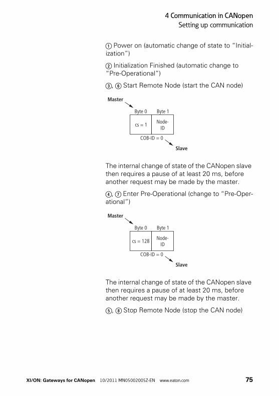
a Power on (automatic change of state to “Initial-ization”)
b Initialization Finished (automatic change to “Pre-Operational”)
c, f Start Remote Node (start the CAN node)
The internal change of state of the CANopen slave then requires a pause of at least 20 ms, before another request may be made by the master.
d, g Enter Pre-Operational (change to “Pre-Oper-ational”)
The internal change of state of the CANopen slave then requires a pause of at least 20 ms, before another request may be made by the master.
e, h Stop Remote Node (stop the CAN node)
Byte 0
Master
Slave
COB-ID = 0
Byte 1
Node-ID
cs = 1
Byte 0
Master
Slave
COB-ID = 0
Byte 1
Node-ID
cs = 128
XI/ON: Gateways for CANopen 10/2011 MN05002005Z-EN www.eaton.com 75

4 Communication in CANopen
Setting up communication
The internal change of state of the CANopen slave then requires a pause of at least 20 ms, before another request may be made by the master.
i, j, k Reset Node (reset complete CAN node)
The execution of this command is confirmed by a boot-up message. This is in the form of a guard frame with the data contents 00hex.
l, m, n Reset Communication (reset communica-tion for the CAN node)
The execution of this command is confirmed by a boot-up message. This is in the form of a guard frame with the data contents 00hex.
Byte 0
Master
Slave
COB-ID = 0
Byte 1
Node-ID
cs = 2
Byte 0
Master
Slave
COB-ID = 0
Byte 1
Node-ID
cs = 129
Byte 0
Master
Slave
COB-ID = 0
Byte 1
Node-ID
cs = 130
76 XI/ON: Gateways for CANopen 10/2011 MN05002005Z-EN www.eaton.com

4 Communication in CANopen
Setting up communication
Identifier for the standard objects
Node-IDThe identifier for each device in a CANopen network is the Node-ID. The CANopen slaves can be assigned the Node-IDs 1 to 127.
Setting of the Node-ID:• XN standard gateways:
→ Chapter “Node-ID setting“, Page 35.
• XNE ECO gateways:→ Chapter “Setting the Node-ID“, Page 56.
COB-IDThe identifier for each communication object in a CANopen network is the COB-ID.
The COB-IDs for the standard objects (digital input, digital output, analog input, analog output) are assigned automatically. The ranges for the COB-IDs are defined by the “Predefined Master-Slave Connection Set”.
Each range for the COB-IDs has 127 numerical values.
The COB-IDs are calculated according to the following rule:
COB-ID = Base-ID + Node-ID
Base-ID: 128; 384; 512; 640; 768; 896; 1024; 1152; 1280; 1408; 1536; 1792
XI/ON: Gateways for CANopen 10/2011 MN05002005Z-EN www.eaton.com 77

4 Communication in CANopen
Setting up communication
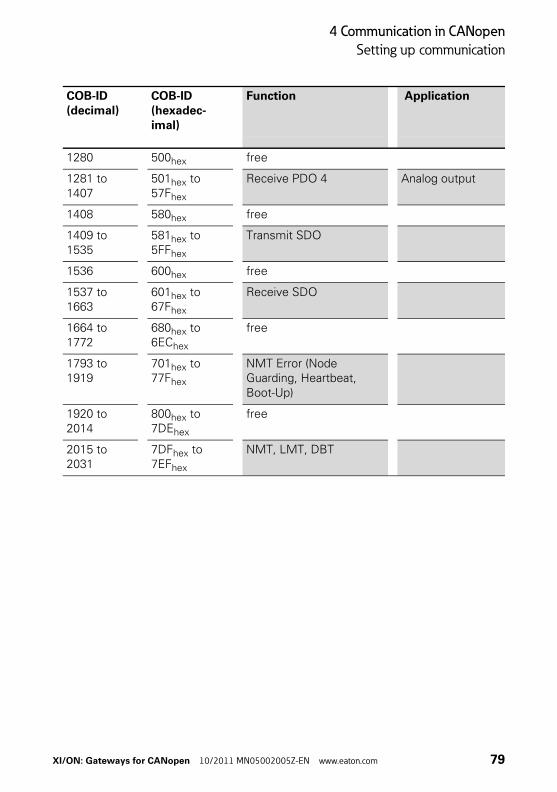
Table 20: Identifiers for Basic Objects
COB-ID(decimal)
COB-ID(hexadec-imal)
Function Application
0 000hex Network Management (NMT)
Broadcast Object
1 to 127 001hex to 07Fhex
free
128 080hex Synchronization (SYNC) Broadcast Object
129 to 255 081hex to 0FFhex
Emergency Message
256 100hex Timestamp Message Broadcast Object
257 to 384 101hex to 180hex
free
385 to 511 181hex to 1FFhex
Transmit PDO 1 Digital input
512 200hex free
513 to 639 201hex to 27Fhex
Receive PDO 1 Digital output
640 280hex free
641 to 767 281hex to 2FFhex
Transmit PDO 2 Analog input
768 300hex free
769 to 895 301hex to 37Fhex
Receive PDO 2 Analog output
896 380hex free
897 to 1023 381hex to 3FFhex
Transmit PDO 3 Analog input
1024 400hex free
1025 to 1151
401hex to 47Fhex
Receive PDO 3 Analog output
1152 480hex free
1153 to 1279
481hex to 4FFhex
Transmit PDO 4 Analog input
78 XI/ON: Gateways for CANopen 10/2011 MN05002005Z-EN www.eaton.com
4 Communication in CANopen
Setting up communication
1280 500hex free
1281 to 1407
501hex to 57Fhex
Receive PDO 4 Analog output
1408 580hex free
1409 to 1535
581hex to 5FFhex
Transmit SDO
1536 600hex free
1537 to 1663
601hex to 67Fhex
Receive SDO
1664 to 1772
680hex to 6EChex
free
1793 to 1919
701hex to 77Fhex
NMT Error (Node Guarding, Heartbeat, Boot-Up)
1920 to 2014
800hex to 7DEhex
free
2015 to 2031
7DFhex to 7EFhex
NMT, LMT, DBT
COB-ID(decimal)
COB-ID(hexadec-imal)
Function Application
XI/ON: Gateways for CANopen 10/2011 MN05002005Z-EN www.eaton.com 79
4 Communication in CANopen
Setting up communication
Setting up Node Guarding protocol
Node Guarding is the name for the monitoring of network nodes by a network manager.
In addition, the CANopen network nodes check that their network manager is operating correctly and that the network is functioning reliably.
In the default state, Node Guarding is inactive.
To activate the Node Guarding protocol at a node, various parameters must be set via the Object Dictionary:
• [100C] = Guard TimeGiven in milliseconds; the query interval (polling) that is to be expected from the network slaveDefault = 0
• [100D] = Life time factorThis factor, multiplied by the Guard Time, produces the time that should elapse after a Node Guarding protocol error until the network slave generates an error message via EMCY. In this way, a temporary communication problem, such as may be caused by heavy bus loading, can be bridged without a Guarding Error.Default = 0
• Guard-IDThis is fixed and cannot be changed.
→ Further information on Node Guarding is provided in the CiA DS-301.
80 XI/ON: Gateways for CANopen 10/2011 MN05002005Z-EN www.eaton.com

4 Communication in CANopen
Setting up communication
Guarding is initiated with the first Guard remote frame (Guarding RTR) from the CANopen network manager.
The Guarding Frame of the network manager has the COBID “1793 - 1 + Node-ID” and does not have a data field.
Furthermore, the RTR bit in the message header must be set and the Data Length code = 1.
The node answers the telegram sent out by the network manager within the preset time (Guard Time) in the “Operational” state, with the data contents 5. The gateway answers the next polling query with the contents 133. The following response from the gateway is with 5 again, and so on. This means that the gateway changes the state of the most significant bit after each query (i.e. the bit is toggled). If the node is in the “Pre-Operational” state, then the value of the data contents of the response telegram toggles between 127 and 255. If the node is in the “Stop” state, the value toggles between 4 and 132.
If there is no query from the network manager within the preset time, then the gateway changes to the state “Guard Fail”. If output modules are fitted in the XI/ON station, then their outputs will be put into defined states, depending on Output Fault Mode and Fault Output States, or will retain the last state that was received. Any RxPDOs that are received will continue to be processed and output. If the Guarding starts up again, the XI/ON gateway leaves the Guard Fail state, but remains in the Pre-Operational state. A “Start Node” must be generated by the network manager in order to restart the XI/ON gateway (see CiA DS-301).
If the setting is Guard Time = 0, then passive Guarding will take place. This means that the gateway answers the Guard Remote frames, without starting its own internal Guard Timer.
XI/ON: Gateways for CANopen 10/2011 MN05002005Z-EN www.eaton.com 81

4 Communication in CANopen
Setting up communication
As an alternative to Node/Life Guarding, the Heart-beat mechanism newly introduced with DS301 V4.0 is supported, which, unlike Guarding, does not require Remote frames.
82 XI/ON: Gateways for CANopen 10/2011 MN05002005Z-EN www.eaton.com

4 Communication in CANopen
XI/ON emergency messages
B
Dc
XI/ON emergency messages
XI/ON CANopen supports Emergency Frames (EMCY).
The COB-IDs for the EMCY telegrams are defined by the Predefined Master-Slave Connection Set:
COB-ID = 129 - 1 + Node-ID
In the event of a communication error, not only the Emergency Error Code but also the Error Register (see “Object 1001hex”) and additional information will be transmitted, so that the error can be more precisely identified. Only a portion of the 5 bytes is used for the additional information. The remaining bytes are then 0.
Table 21: Data contents of the Emergency Frame
yte 0 1 2 3 4 5 6 7
ata ontents
Emer-gency Error Code
Error Register
Additional information
XI/ON: Gateways for CANopen 10/2011 MN05002005Z-EN www.eaton.com 83

4 Communication in CANopen
XI/ON emergency messages
Table 22: Bit assignments for the Error Register
1) M = mandatory
2) O = optional
The contents of the error register are frequently displayed as a decimal or hexadecimal value. An overview of the possible decimal and hexadecimal values and their assignments to the individual bits of the error register is provided in the Appendix.
Emergency Frames are sent out by the gateway autonomously, if one of the following error condi-tions occurs:
Error Register
M/O Meaning
Bit 0 M1) Generate the error message
Bit 1 O2) Current error
Bit 2 O Voltage error message
Bit 3 O Temperature error
Bit 4 O Communication error (Overrun, Error State)
Bit 5 O Device-profile specific error
Bit 6 O reserved
Bit 7 O Manufacturer-specific error
84 XI/ON: Gateways for CANopen 10/2011 MN05002005Z-EN www.eaton.com

4 Communication in CANopen
XI/ON emergency messages
Table 23: Overview of byte 0 to 5 of the CANopen Emergency Frames
Designa-tion
Byte 0,1 Byte 2 Byte 3 Byte 4 Byte 5 Meaning
Error code
Error regis-ter
Additional information1)2)
Error Reset / No Error
0000hex – 0 0 0 Error reset
Input current too high
2110hex Bit 1 = 1 Module No.
Chn. No.
0 XN-#AI-I(0/4…20MA), XN-4AI-U/I:The input current is outside of the permissible range (threshold: 1 % over the upper measurement range value or 1 % below the lower measurement range value).
Input current too low
2130hex Bit 1 = 1 Module No.
Chn. No.
0 XN-#AI-I(0/4…20MA), XN-4AI-U/I:Open circuit or input current for the measuring range 4…20 mA too low. The threshold is 3 mA.
Output current too high
2310hex Bit 1 = 1 Module No.
Chn. No.
0 XN-#DO-24VDC-…, XN-1CNT-24VDC:Output current too high
2310hex Bit 1 = 1 Module No.
Chn. No.
0 XN-2AI-PT/NI-2/3:Current too high (threshold: approx. 5 Ω; only with temperature measuring ranges)
XI/ON: Gateways for CANopen 10/2011 MN05002005Z-EN www.eaton.com 85

4 Communication in CANopen
XI/ON emergency messages
Output current out of range
2323hex Bit 1 = 1 Module No.
Chn. No.
0 XN-2AI-PT/NI-2/3:The current is outside of the permissible range (threshold: 1 % of the posi-tive measurement range limit value; unterflow diag-nostics only in temperature measurements).
2323hex Bit 1 = 1 Module No.
Chn. No.
0 XN-1CNT-24VDC:The output current is outside of the permissible range.
Load dump at outputs
2330hex Bit 1 = 1 Module No.
Chn. No.
0 XN-2AI-PT/NI-2/3:Open circuit or current too low (threshold: positive converter limit value)
AI U voltage out of range
3003hex Bit 2 = 1 Module No.
Chn. No.
0 XN-#AI-U(-10/0…+10VDC),XN-4AI-U/I:The input voltage is outside of the permissible range (threshold: 1 % over the upper measurement range value or 1 % below the lower measurement range value).
AI U voltage out of range
3003hex Bit 2 = 1 Module No.
Chn. No.
0 XN-2AI-THERMO-PI:Open circuit (only in temperature measure-ments) or input voltage is outside of the permissible range (threshold: 1 % of the positive measurement range limit value).
Designa-tion
Byte 0,1 Byte 2 Byte 3 Byte 4 Byte 5 Meaning
Error code
Error regis-ter
Additional information1)2)
86 XI/ON: Gateways for CANopen 10/2011 MN05002005Z-EN www.eaton.com

4 Communication in CANopen
XI/ON emergency messages
Mains voltage too high
3110hex Bit 2 = 1 0 Chn. No.
0 System voltage too high
Mains voltage too low
3120hex Bit 2 = 1 Module No.3)
Chn. No.
0 System voltage too low
Output voltage too low
3320hex Bit 2 = 1 Module No.
Chn. No.
0 Field voltage too low
Addi-tional modules
7000hex Bit 7 = 1 Module No.
Chn. No.
See column mea-ning
XN-1SSI4):Setting of byte 5:01hex = SSI diag02hex = SSI error04hex = Overflow error08hex = Underflow error10hex = Parameter error
7000hex Bit 7 = 1 Module No.
Chn. No.
See column mea-ning
XN-1RS232, XN-1RS485/4224):Setting of byte 5:08hex = Parameter error10hex = Hardware failure20hex = Handshake error40hex = Frame error80hex = RX buffer overflow
Addi-tional modules
7000hex Bit 7 = 1 Module No.
Chn. No.
Chan-nel diag-nostic
XNE-8AI-U/I-4PT/NI, XNE-4AO-U/I:Furture information about the channel diagnostic (byte 5) of the respective module, you can find in: User Manual XI/ON: Analog I/O Modules.
XNE-1SWIRE:At error code 7000hex of XNE-1SWIRE, all z bytes are used. Description see Table 24, Page 89.
Designa-tion
Byte 0,1 Byte 2 Byte 3 Byte 4 Byte 5 Meaning
Error code
Error regis-ter
Additional information1)2)
XI/ON: Gateways for CANopen 10/2011 MN05002005Z-EN www.eaton.com 87
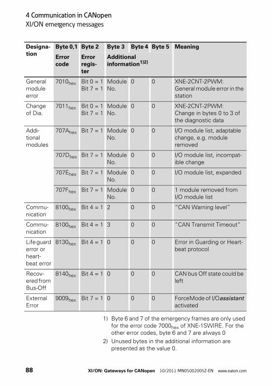
4 Communication in CANopen
XI/ON emergency messages
1) Byte 6 and 7 of the emergency frames are only used for the error code 7000hex of XNE-1SWIRE. For the other error codes, byte 6 and 7 are always 0
2) Unused bytes in the additional information are presented as the value 0.
General module error
7010hex Bit 0 = 1Bit 7 = 1
Module No.
0 0 XNE-2CNT-2PWM:General module error in the station
Change of Dia.
7011hex Bit 0 = 1Bit 7 = 1
Module No.
0 0 XNE-2CNT-2PWM:Change in bytes 0 to 3 of the diagnostic data
Addi-tional modules
707Ahex Bit 7 = 1 Module No.
0 0 I/O module list, adaptable change, e.g. module removed
707Dhex Bit 7 = 1 Module No.
0 0 I/O module list, incompat-ible change
707Ehex Bit 7 = 1 Module No.
0 0 I/O module list, expanded
707Fhex Bit 7 = 1 Module No.
0 0 1 module removed from I/O module list
Commu-nication
8100hex Bit 4 = 1 2 0 0 “CAN Warning level”
Commu-nication
8100hex Bit 4 = 1 3 0 0 “CAN Transmit Timeout”
Life guard error or heart-beat error
8130hex Bit 4 = 1 0 0 0 Error in Guarding or Heart-beat protocol
Recov-ered from Bus-Off
8140hex Bit 4 = 1 0 0 0 CAN bus Off state could be left
External Error
9009hex Bit 7 = 1 0 0 0 ForceMode of I/Oassistant activated
Designa-tion
Byte 0,1 Byte 2 Byte 3 Byte 4 Byte 5 Meaning
Error code
Error regis-ter
Additional information1)2)
88 XI/ON: Gateways for CANopen 10/2011 MN05002005Z-EN www.eaton.com

4 Communication in CANopen
XI/ON emergency messages
3) If the error message refers to the gateway itself (voltage error for XN-GWBR-CANopen), then the value 0 will be reported for the module number and the channel number.
4) It is only possible to interpret this additional informa-tion if the type of module that is affected is known from the module number.
Table 24: Error code 7000hex of XNE-1SWIRE
1) Bytes 6 and 7 of the emergency frame contain the result of the bit OR operation of the stated diag bytes.
The Error Code for an Emergency Frame can only be read with the assistance of specific analysis tools.
Boot-up message
After initialization (after Power-On, Reset-Node and Reset-Communication), a Boot-up message according to CiA DS-301 V4.0 is sent out. This is in the form of a Guard Frame with the contents 00hex.
Under certain circumstances, a network manager may fail to detect the temporary drop-out of a XI/ON gateway (for example, as a result of voltage fluctuations). This could occur under the following conditions:
• The drop-out and initialization of the gateway happen in the time between two Guarding Frames
Designa-tion
Byte 0,1 Byte 2 Byte 3 Byte 4 Byte 5 Byte 6 Byte 7
Error code
Error register
Additional information
Additional modules
7000hex Bit 7 = 1 Module No.
Diag-byte 0
Diag-byte 1
Diag-byte 2| 4 | 6
Diag-byte 3| 5 | 7
XI/ON: Gateways for CANopen 10/2011 MN05002005Z-EN www.eaton.com 89

4 Communication in CANopen
XI/ON emergency messages
• The gateway was already in the Pre-Operational state beforehand
• The last state of the toggle bit was 1
If a Boot-up message is sent out after a reset or initialization, then the drop-out mentioned above will also not be missed by the network manager.
90 XI/ON: Gateways for CANopen 10/2011 MN05002005Z-EN www.eaton.com
4 Communication in CANopen
Parameterization by means of Service Data Objects (SDO)
Parameterization by meansof Service Data Objects (SDO)
SDO (= Service Data Object) is a confirmed CANopen service that is primarily used for param-eterization and configuration of the CANopen slaves (XI/ON) and less frequently for transmitting process data. “Confirmed” means that a XI/ON-CANopen gateway (SDO server) that is addressed by this procedure must acknowledge it with a response. In this way, the SDO client obtains infor-mation about whether the XI/ON gateway that it addressed was contacted, and whether the access was achieved without any errors (error code in the response from the SDO server). SDO access means that the contents of the Object Dictionary entries for an SDO server can be read or written, and that the settings for an XI/ON station can be made in this way.
Four parallel SDO servers are supported. There are three “additional” SDOs, as well as the default SDO. As a default, these are inactive, but can be parameterized and enabled through the Object Dictionary entries 1201hex to 1203hex.
The communication parameters for the default SDO follow the Predefined Connection Set, and cannot be modified (see CiA DS-301, V4.01)
In the following representations of the messages, the identifier of the CANopen message that is to be transmitted is shown below the frame, and the content of the data bytes to be transmitted are shown inside the frame.
The following representations use the Expedited SDO Transfer, i.e. a maximum of 4 bytes of user data can be transferred.
→ CANopen also offers the possibility of segmented SDO-transfer of data with data length of more than 4 bytes.
XI/ON: Gateways for CANopen 10/2011 MN05002005Z-EN www.eaton.com 91

4 Communication in CANopen
Parameterization by means of Service Data Objects (SDO)
Read (Read from Object Dictionary)
x ... depending on the length of data read
(see CiA DS-301)
The stated COB-ID refers to the default SDO server.
00 0 0
Byte 0
Byte 0
Byte 4
Byte 4
Byte 2
Byte 2
Byte 6
Byte 6
Byte 1
Byte 1
Byte 5
Byte 5
Byte 3
Byte 3
Byte 7
Byte 7
CCS =40h
SCS =4xh
Index
lsb msb
Index
lsb msbSub-Index
Sub-Index Data
COB-ID = 1537 + Node-ID - 1
COB-ID = 1409 + Node-ID - 1
Client
Client
Server
lsb = least significant byte
msb
= most significant byte
SCS = Server Command Specifier
CCS
= Client Command Spec-ifier
→ The XI/ON gateway generates length informa-tion as to how many data bytes are to be read (see CiA DS-301). This information is found in byte 0 “SCS = 4xh”. The value x depends on the length of data read.
92 XI/ON: Gateways for CANopen 10/2011 MN05002005Z-EN www.eaton.com

4 Communication in CANopen
Parameterization by means of Service Data Objects (SDO)
Write (Write to Object Dictionary)
(see CiA DS-301)
The stated COB-ID refers to the default SDO server.
Byte 0
Byte 0
Byte 4
Byte 4
Byte 2
Byte 2
Byte 6
Byte 6
Byte 1
Byte 1
Byte 5
Byte 5
Byte 3
Byte 3
Byte 7
Byte 7
Index
lsb msb
Index
lsb msbSub-Index
Sub-Index reserved
COB-ID = 1537 + Node-ID - 1
COB-ID = 1409 + Node-ID - 1
Client
Client
Server
DataCCS =2xh
SCS =60h
lsb = least significant byte
msb
= most significant byte
SCS = Server Command Specifier
CCS
= Client Command Spec-ifier
→ The information in byte 0 “CCS = 2xh” can optionally contain the length information for the transmitted data bytes (see CiA DS-301). The information byte 0 “CCS = 20h” means that no length information is present.
Attention!If an incorrect data length is given, the error code “Abort SDO Transfer Service” will be generated (see CiA DS-301).
XI/ON: Gateways for CANopen 10/2011 MN05002005Z-EN www.eaton.com 93

4 Communication in CANopen
Parameterization by means of Service Data Objects (SDO)
Table 25: Cancel codes for errors in data length infor-mation
Cancel code Description
0607 0012hex Data length of Service parameter is too large
0607 0013hex Data length of Service parameter is too short
94 XI/ON: Gateways for CANopen 10/2011 MN05002005Z-EN www.eaton.com

4 Communication in CANopen
Parameterization by means of Service Data Objects (SDO)
Example:
Write a new COB-ID for RxPDO 1 (ID = 258hex)
Commanded parameter storing / restoring
Saving of communication and application parame-ters is executed by a command. This means that the parameters transferred through an SDO are held in volatile memory, until they are saved by using the command “Store Parameters” (Object 1010hex, sub-indices 0 to 3). All the communica-tion and application parameters that are supported by the gateway will be saved.
The command “Restore Default Parameters” (Object 1011hex, sub-indices 0 to 3) is also supported. This command resets all the communi-cation and/or application parameters to the default values.
Byte 0
Byte 0
Byte 4
Byte 4
Byte 2
Byte 2
Byte 6
Byte 6
Byte 1
Byte 1
Byte 5
Byte 5
Byte 3
Byte 3
Byte 7
Byte 7
22h
60h 1400h
1400h 1h
1h reserviert
258h
COB-ID = 1537 + Node-ID - 1
COB-ID = 1409 + Node-ID - 1
Client
Client
Server
XI/ON: Gateways for CANopen 10/2011 MN05002005Z-EN www.eaton.com 95
4 Communication in CANopen
Transmission of Process Data Objects (PDO)
Transmission of Process Data Objects (PDO)
CANopen provides PDO communication (PDO = Process Data Object). PDOs are fast real-time process data that are handled as unconfirmed services without a protocol overhead. PDOs can contain a maximum of 8 bytes of data. They can be assembled and configured by the user to suit the specific requirements. In addition, there are a number of transmission/transfer settings (Trans-mission Types) for process data.
The following attributes can be set for each PDO by means of the object “PDO Communication Parameter”:
Communication parameter COB-ID
The COB-ID is the CAN identifier that is used for the transmission (Object 1800hex ff).
COB-IDs are used to define the priority of the message telegrams. The lowest COB-ID has the highest priority.
For communication between 2 nodes, the COB-ID of the transmit PDO must be the same as the COB-ID of the receive PDO.
All other PDOs are inactive. This state can be seen from the invalid bit (Bit 31) of the COB-ID.
→ As delivered, each XI/ON gateway has from none to eight active PDOs, with COB-IDs that are taken from the Predefined Master-Slave Connection Set.
96 XI/ON: Gateways for CANopen 10/2011 MN05002005Z-EN www.eaton.com
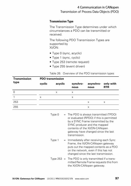
4 Communication in CANopen
Transmission of Process Data Objects (PDO)
Transmission Type
The Transmission Type determines under which circumstances a PDO can be transmitted or received.
The following PDO Transmission Types are supported by XI/ON:
• Type 0 (sync, acyclic)
• Type 1 (sync, cyclic)
• Type 253 (remote request)
• Type 255 (event driven)
Table 26: Overview of the PDO transmission types
Transmission type
PDO transmission
cyclic acyclic synchro-nous
asynchro-nous
only with RTR
0 x x
1 x x
253 x x
255 x
Type 0 = The PDO is always transmitted (TPDO) or evaluated (RPDO) if this is permitted by a SYNC Frame transmitted by the SYNC producer and the mapped contents of the XI/ON-CANopen gateway have changed since the last transmission.
Type 1 = Immediately after receiving each Sync Frame, the XI/ON-CANopen gateway puts out the mapped contents as a PDO on the network, even if this has not changed since the last transmission.
Type 253 = The PDO is only transmitted if a trans-mitted Remote Frame requests this from the XI/ON-CANopen gateway.
XI/ON: Gateways for CANopen 10/2011 MN05002005Z-EN www.eaton.com 97

4 Communication in CANopen
Transmission of Process Data Objects (PDO)
The Transmission Types of the individual PDOs are independent, which means that a freely mixed operation with synchronous and asynchronous PDOs is possible.
Inhibit Time
An Inhibit Time setting for the PDOs (Object 1800hex ff, sub-index 03hex) is only supported for TPDOs. Unlike the other time values, which are given as multiples of 1 ms, the Inhibit Time is defined as a multiple of 100 μs. However, since the time resolution of the system clock in the XI/ON-CANopen gateway is 1 ms, Inhibit Time values below 10 × 100 μs have no effect.
Attention!This Transmission Type is only permissible for TPDOs.
Type 255 = In this mode of operation, the XI/ON-CANopen gateway does not depend on any Sync or Remote Request for PDO communication. Whenever this is provided for an internal event within the XI/ON-CANopen gateway, the gateway will transmit a PDO to the CANopen network.
98 XI/ON: Gateways for CANopen 10/2011 MN05002005Z-EN www.eaton.com

4 Communication in CANopen
Transmission of Process Data Objects (PDO)
Event Time
The Event Time (Object 1800hex ff, sub-index 05hex) defines the maximum interval after which a TPDO will be transmitted, even though no event has occurred. This means that the Event Time determines the maximum interval between two transmissions of a TPDO.
The expiry of the interval set for the Event Time is detected as an event. If any other event occurs, the Event Time is reset and restarted.
The value of the object is interpreted as a multiple of 1 ms.
Available PDOs
64 PDOs are supported:
• 32 Receive PDOs: TPDO1 to TPDO32 (Index 1800hex to 181Fhex)
• 32 Transmit PDOs: RPDO1 to RPDO32 (Index 1400hex to 141Fhex)
The Default Master-Slave Connection Set is supported for each of the PDOs 1 to 4, so that a COB-ID distribution is not necessary for these PDOs.
If one of the COB-IDs from xPDO1 to xPDO4 is reconfigured, then the use of a COB-ID from the Default Master-Slave Connection Set can be achieved by setting this COB-ID to 0.
XI/ON: Gateways for CANopen 10/2011 MN05002005Z-EN www.eaton.com 99

4 Communication in CANopen
Transmission of Process Data Objects (PDO)
Mapping of objects in PDOs
Mapping is the assignment of objects from an Object Dictionary to a PDO for transmission/recep-tion via the CAN bus. More than one object can be transmitted in a single PDO.
The Mapping Parameters determine which items of information are transmitted in a PDO:
Table 27: Object dictionary entries or mapping parame-ters
PDO Object dictionary entries
Type Range Range
Transmit PDOs
TPDO1 to TPDO32
1A00hex to 1A1Fhex
Receive PDOs
RPDO1 to RPDO32
1600hex to 161Fhex
100 XI/ON: Gateways for CANopen 10/2011 MN05002005Z-EN www.eaton.com
4 Communication in CANopen
Transmission of Process Data Objects (PDO)
Default PDOs and PDO mappings
The 4 Transmit and 4 Receive PDOs which are specified by the Communication Profile CiA DS-301 are supported by XI/ON. The mapping of these PDOs and their Transmission Types are specified by the I/O-Device Profile CiA DS-401.
In addition to the default PDOs which are stan-dardized by the CiA DS-301 and DS-401 profiles, other PDOs for an XI/ON-CANopen gateway may be provided with mapping entries and communication parameters. These additional PDOs (5 to 16) are set to “Invalid” by default.
Default PDOs as per CiA DS-301 and DS-401The TPDOs of the following table have the following properties:
• The COB-ID is part of sub-index 01hex
• The PDO is active!The first digit of the 8-digit hexadecimal number of the COB-ID also indicates whether the PDO is enabled. Active PDOs are identified by a HEX digit < 7. Normally the digits 0 or 4 are used. → Table 71, Page 157.
→ The Default PDOs are only activated if the objects and sub-indices intended for the corre-sponding PDO actually exist. If, for instance, no analog I/Os are used in a XI/ON station, then the PDOs 2 to 4 are set to “Invalid” and no mapping entries will be present.
XI/ON: Gateways for CANopen 10/2011 MN05002005Z-EN www.eaton.com 101

4 Communication in CANopen
Transmission of Process Data Objects (PDO)
Table 28: Overview of the default TPDOs as per CiA DS-301 and DS-401
Table 29: Overview of the default RPDOs as per CiA DS-301 and DS-401
Meaning TPDO Sub-index 01hex -“COB-ID”
1st group, digital input chan-nels (bits 0 to 63)
PDO11800hex
0000 0180hex + Node-ID
1st group, analog input chan-nels (channels 0 to 3)
PDO21801hex
0000 0280hex + Node-ID
2nd group, analog input chan-nels (channels 4 to 7)
PDO31802hex
0000 0380hex + Node-ID
3rd group, analog input chan-nels (channels 8 to 11)
PDO41803hex
0000 0480hex + Node-ID
Meaning RPDO COB-ID
1st group, digital output chan-nels (bits 0 to 63)
PDO11400hex
0000 0200hex + Node-ID
1st group, analog output chan-nels (channels 0 to 3)
PDO21401hex
0000 0300hex + Node-ID
2nd group, analog output chan-nels (channels 4 to 7)
PDO31402hex
0000 0400hex + Node-ID
3rd group, analog output chan-nels (channels 8 to 11)
PDO41403hex
0000 0500hex + Node-ID
102 XI/ON: Gateways for CANopen 10/2011 MN05002005Z-EN www.eaton.com

4 Communication in CANopen
Transmission of Process Data Objects (PDO)
XI/ON-specific default PDOsThese additional PDOs are always set to “Invalid” by default.
The relevant parameters must be checked before enabling these PDOs. This particularly applies to the COB-IDs as these come from the Default Master-Slave Connection Set and are assigned to other Node-IDs. The network should not therefore contain nodes with the corresponding node ID, and these nodes should not use the corresponding COB IDs. The transmission type of these PDOs is normally 255.
XI/ON: Gateways for CANopen 10/2011 MN05002005Z-EN www.eaton.com 103
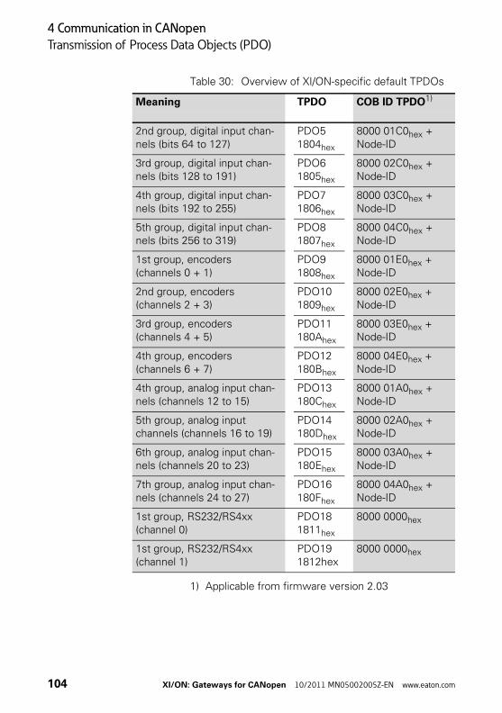
4 Communication in CANopen
Transmission of Process Data Objects (PDO)
Table 30: Overview of XI/ON-specific default TPDOs
1) Applicable from firmware version 2.03
Meaning TPDO COB ID TPDO1)
2nd group, digital input chan-nels (bits 64 to 127)
PDO51804hex
8000 01C0hex + Node-ID
3rd group, digital input chan-nels (bits 128 to 191)
PDO61805hex
8000 02C0hex + Node-ID
4th group, digital input chan-nels (bits 192 to 255)
PDO71806hex
8000 03C0hex + Node-ID
5th group, digital input chan-nels (bits 256 to 319)
PDO81807hex
8000 04C0hex + Node-ID
1st group, encoders (channels 0 + 1)
PDO91808hex
8000 01E0hex + Node-ID
2nd group, encoders (channels 2 + 3)
PDO101809hex
8000 02E0hex + Node-ID
3rd group, encoders (channels 4 + 5)
PDO11180Ahex
8000 03E0hex + Node-ID
4th group, encoders (channels 6 + 7)
PDO12180Bhex
8000 04E0hex + Node-ID
4th group, analog input chan-nels (channels 12 to 15)
PDO13180Chex
8000 01A0hex + Node-ID
5th group, analog input channels (channels 16 to 19)
PDO14180Dhex
8000 02A0hex + Node-ID
6th group, analog input chan-nels (channels 20 to 23)
PDO15180Ehex
8000 03A0hex + Node-ID
7th group, analog input chan-nels (channels 24 to 27)
PDO16180Fhex
8000 04A0hex + Node-ID
1st group, RS232/RS4xx (channel 0)
PDO181811hex
8000 0000hex
1st group, RS232/RS4xx (channel 1)
PDO191812hex
8000 0000hex
104 XI/ON: Gateways for CANopen 10/2011 MN05002005Z-EN www.eaton.com
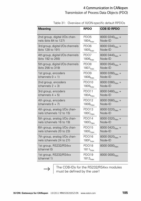
4 Communication in CANopen
Transmission of Process Data Objects (PDO)
Table 31: Overview of XI/ON-specific default RPDOs
Meaning RPDO COB ID RPDO
2nd group, digital I/Os chan-nels (bits 64 to 127)
PDO51804hex
8000 0240hex + Node-ID
3rd group, digital I/Os channels (bits 128 to 191)
PDO61805hex
8000 0340hex + Node-ID
4th group, digital I/Os channels (bits 192 to 255)
PDO71806hex
8000 0440hex + Node-ID
5th group, digital I/Os channels (bits 256 to 319)
PDO81807hex
8000 0540hex + Node-ID
1st group, encoders (channels 0 + 1)
PDO91808hex
8000 0260hex + Node-ID
2nd group, encoders (channels 2 + 3)
PDO101809hex
8000 0360hex + Node-ID
3rd group, encoders (channels 4 + 5)
PDO11180Ahex
8000 0460hex + Node-ID
4th group, encoders (channels 6 + 7)
PDO12180Bhex
8000 0560hex + Node-ID
4th group, analog I/Os chan-nels (channels 12 to 15)
PDO13180Chex
8000 0220hex + Node-ID
5th group, analog I/Os chan-nels (channels 16 to 19)
PDO14180Dhex
8000 0320hex + Node-ID
6th group, analog I/Os chan-nels (channels 20 to 23)
PDO15180Ehex
8000 0420hex + Node-ID
7th group, analog I/Os chan-nels (channels 24 to 27)
PDO16180Fhex
8000 0520hex + Node-ID
1st group, RS232/RS4xx (channel 0)
PDO181811hex
8000 0000hex
1st group, RS232/RS4xx (channel 1)
PDO191812hex
8000 0000hex
→ The COB-IDs for the RS232/RS4xx modules must be defined by the user!
XI/ON: Gateways for CANopen 10/2011 MN05002005Z-EN www.eaton.com 105
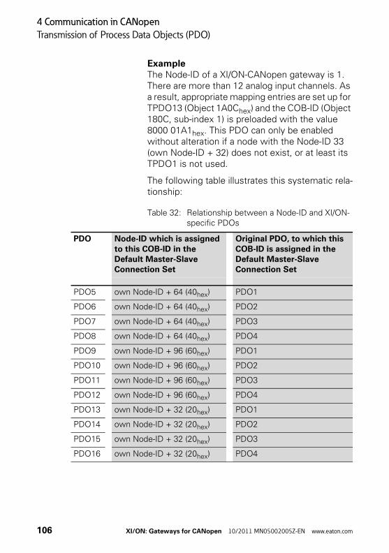
4 Communication in CANopen
Transmission of Process Data Objects (PDO)
ExampleThe Node-ID of a XI/ON-CANopen gateway is 1. There are more than 12 analog input channels. As a result, appropriate mapping entries are set up for TPDO13 (Object 1A0Chex) and the COB-ID (Object 180C, sub-index 1) is preloaded with the value 8000 01A1hex. This PDO can only be enabled without alteration if a node with the Node-ID 33 (own Node-ID + 32) does not exist, or at least its TPDO1 is not used.
The following table illustrates this systematic rela-tionship:
Table 32: Relationship between a Node-ID and XI/ON-specific PDOs
PDO Node-ID which is assigned to this COB-ID in the Default Master-Slave Connection Set
Original PDO, to which this COB-ID is assigned in the Default Master-Slave Connection Set
PDO5 own Node-ID + 64 (40hex) PDO1
PDO6 own Node-ID + 64 (40hex) PDO2
PDO7 own Node-ID + 64 (40hex) PDO3
PDO8 own Node-ID + 64 (40hex) PDO4
PDO9 own Node-ID + 96 (60hex) PDO1
PDO10 own Node-ID + 96 (60hex) PDO2
PDO11 own Node-ID + 96 (60hex) PDO3
PDO12 own Node-ID + 96 (60hex) PDO4
PDO13 own Node-ID + 32 (20hex) PDO1
PDO14 own Node-ID + 32 (20hex) PDO2
PDO15 own Node-ID + 32 (20hex) PDO3
PDO16 own Node-ID + 32 (20hex) PDO4
106 XI/ON: Gateways for CANopen 10/2011 MN05002005Z-EN www.eaton.com

4 Communication in CANopen
Transmission of Process Data Objects (PDO)
Mappable objects
The maximum of 64 mapping entries per PDO that is specified by Communication Profile CiA DS-301 is supported.
The following objects from the Object Dictionary can be mapped:
Table 33: Overview of mappable objects
Name Index Subindex Direction
Dummy Mapping Boolean 0001hex - Receive
Dummy Mapping Boolean Integer8
0002hex - Receive
Dummy Mapping Boolean Integer16
0003hex - Receive
Dummy Mapping Boolean Integer32
0004hex - Receive
Dummy Mapping Boolean Unsigned8
0005hex - Receive
Dummy Mapping Boolean Unsigned16
0006hex - Receive
Dummy Mapping Boolean Unsigned32
0007hex - Receive
Error Register 1001hex - Transmit
Manu Spec Analog Input Range 5420hex 1 to n Transmit
RS232/RS4xx RxD 5601hex 1 to n Receive
RS232/RS4xx TxD 5602hex 1 to n Transmit
Encoder Status 5802hex 1 to n Transmit
Encoder Flags 5803hex 1 to n Transmit
SSI Native Status 5805hex 1 to n Transmit
SSI Optional Encoder Status 5806hex 1 to n Transmit
Encoder Control 5808hex 1 to n Receive
Read Input 8-Bit 6000hex 1 to n Transmit
Read Input Bit (1 to 128)1) 6020hex 1 to n Transmit
XI/ON: Gateways for CANopen 10/2011 MN05002005Z-EN www.eaton.com 107

4 Communication in CANopen
Transmission of Process Data Objects (PDO)
1) Objects XXX1 and XXX2 will be generated if the number of digital input or output channels exceeds the value 128 or 256 respectively.
Read Input 16-Bit 6100hex 1 to n Transmit
Read Input 32-Bit 6120hex 1 to n Transmit
Write Output 8-Bit 6200hex 1 to n Receive
Write Output Bit (1 to 128)1) 6220hex 1 to n Receive
Write Output 16-Bit 6300hex 1 to n Receive
Write Output 32-Bit 6320hex 1 to n Receive
Read Analog Input 16-Bit 6401hex 1 to n Transmit
Write Analog Output 16-Bit 6411hex 1 to n Receive
Position Value for Multi-Sensor Devices
6820hex 1 to n Transmit
Cam1 State Register 6B00hex 1 to n Transmit
Area State Register 6C00hex 1 to n Transmit
Name Index Subindex Direction
108 XI/ON: Gateways for CANopen 10/2011 MN05002005Z-EN www.eaton.com

4 Communication in CANopen
Transmission of Process Data Objects (PDO)
Procedure for altering PDO mappings
The Communication Profile CiA DS-301 Version 4 defines a detailed procedure for altering PDO mappings.
For the XI/ON gateway, this results in the following method for modifying PDO mappings:
• • The node state of the gateway must be “Pre-Operational” (Bus LED orange).
• • The number of mapping entries (Sub-index 0) for a PDO must be set to 0.
• The mapping entries (Sub-index 1 to 64) can be written.
• The number of mapping entries (Sub-index 0) must now be set to the valid number of mapped objects.
• Alternatively, the new mapping can be saved in non-volatile memory (Store Communication Parameters).
The following Cancel Codes (Abort Domain Protocol) may be sent back by the gateway if there is an error:
XI/ON: Gateways for CANopen 10/2011 MN05002005Z-EN www.eaton.com 109

4 Communication in CANopen
Transmission of Process Data Objects (PDO)
Table 34: Cancel codes
Cancel code Description as per CiA DS-301
Possible cause
0604 0041hex Object cannot be mapped
Invalid Object-Index transferred while writing the mapping entries.
0604 0042hex Number or length of the objects exceeds the PDO length
Attempted to map too many or exces-sively long objects to a PDO. This will be returned on writing to the Sub-index 0.
0609 0011hex Sub-index does not exist
A Sub-index > 64 was addressed.
0800 022hex Access not possible in this node state
Write access is only possible in the “Pre-Operational” node state. Write access to Sub-indices 1 to 64 is only possible if Sub-index 0 is written with the value 0.
110 XI/ON: Gateways for CANopen 10/2011 MN05002005Z-EN www.eaton.com
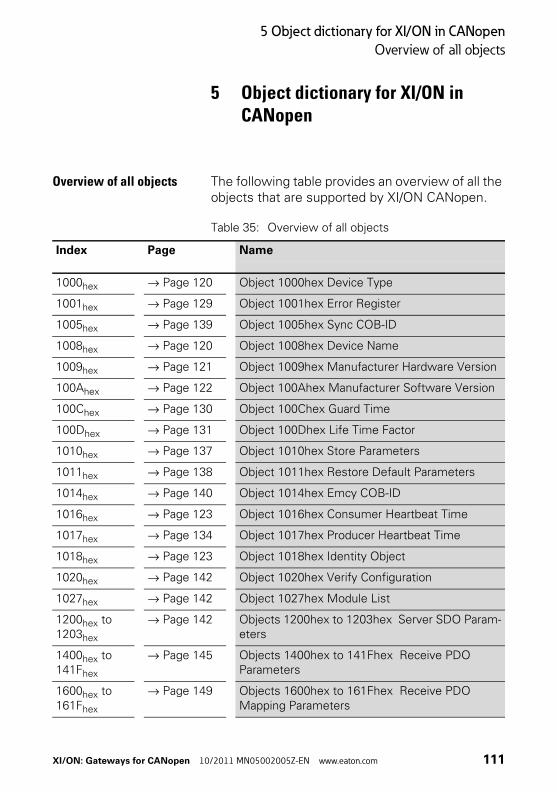
5 Object dictionary for XI/ON in CANopen
Overview of all objects
5 Object dictionary for XI/ON in CANopen
Overview of all objects The following table provides an overview of all the objects that are supported by XI/ON CANopen.
Table 35: Overview of all objects
Index Page Name
1000hex → Page 120 Object 1000hex Device Type
1001hex → Page 129 Object 1001hex Error Register
1005hex → Page 139 Object 1005hex Sync COB-ID
1008hex → Page 120 Object 1008hex Device Name
1009hex → Page 121 Object 1009hex Manufacturer Hardware Version
100Ahex → Page 122 Object 100Ahex Manufacturer Software Version
100Chex → Page 130 Object 100Chex Guard Time
100Dhex → Page 131 Object 100Dhex Life Time Factor
1010hex → Page 137 Object 1010hex Store Parameters
1011hex → Page 138 Object 1011hex Restore Default Parameters
1014hex → Page 140 Object 1014hex Emcy COB-ID
1016hex → Page 123 Object 1016hex Consumer Heartbeat Time
1017hex → Page 134 Object 1017hex Producer Heartbeat Time
1018hex → Page 123 Object 1018hex Identity Object
1020hex → Page 142 Object 1020hex Verify Configuration
1027hex → Page 142 Object 1027hex Module List
1200hex to 1203hex
→ Page 142 Objects 1200hex to 1203hex Server SDO Param-eters
1400hex to 141Fhex
→ Page 145 Objects 1400hex to 141Fhex Receive PDO Parameters
1600hex to 161Fhex
→ Page 149 Objects 1600hex to 161Fhex Receive PDO Mapping Parameters
XI/ON: Gateways for CANopen 10/2011 MN05002005Z-EN www.eaton.com 111
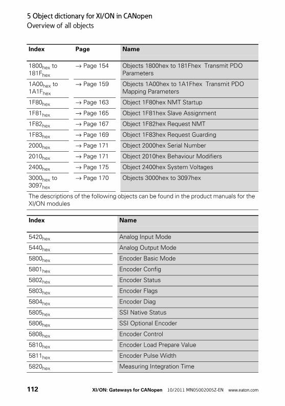
5 Object dictionary for XI/ON in CANopen
Overview of all objects
1800hex to 181Fhex
→ Page 154 Objects 1800hex to 181Fhex Transmit PDO Parameters
1A00hex to 1A1Fhex
→ Page 159 Objects 1A00hex to 1A1Fhex Transmit PDO Mapping Parameters
1F80hex → Page 163 Object 1F80hex NMT Startup
1F81hex → Page 165 Object 1F81hex Slave Assignment
1F82hex → Page 167 Object 1F82hex Request NMT
1F83hex → Page 169 Object 1F83hex Request Guarding
2000hex → Page 171 Object 2000hex Serial Number
2010hex → Page 171 Object 2010hex Behaviour Modifiers
2400hex → Page 175 Object 2400hex System Voltages
3000hex to 3097hex
→ Page 170 Objects 3000hex to 3097hex
The descriptions of the following objects can be found in the product manuals for the XI/ON modules
Index Name
5420hex Analog Input Mode
5440hex Analog Output Mode
5800hex Encoder Basic Mode
5801hex Encoder Config
5802hex Encoder Status
5803hex Encoder Flags
5804hex Encoder Diag
5805hex SSI Native Status
5806hex SSI Optional Encoder
5808hex Encoder Control
5810hex Encoder Load Prepare Value
5811hex Encoder Pulse Width
5820hex Measuring Integration Time
Index Page Name
112 XI/ON: Gateways for CANopen 10/2011 MN05002005Z-EN www.eaton.com

5 Object dictionary for XI/ON in CANopen
Overview of all objects
5821hex Measuring Low Limit
5822hex Measuring High Limit
5823hex Measuring Units per Revolution
5824hex Encoder Measuring Divisor
5825hex Encoder Measuring Factor
5827hex Encoder Measuring Time Out
5830hex Encoder Measuring Value
5831hex Encoder Latch Value
5901hex PWM Config
5902hex PWM Status
5903hex PWM Flags
5904hex PWM Diag
5908hex PWM Control
5910hex PWM Load Prepare Value
5913hex PWM Duty Cycle
5920hex PWM Period Duration
5931hex PWM Latch Value
6000hex Read Input 8-Bit
6020hex Read Input Bit 1 to 128
6021hex Read Input Bit 129 to 256
6022hex Read Input Bit 257 to 288
6100hex Read Input 16-Bit
6120hex Read Input 32-Bit
6200hex Write Output 8-Bit
6206hex Error Mode Output 8-Bit
6207hex Error Value Output 8-Bit
6220hex to 6222hex Write Output Bit 1 to 128 to Write Output Bit 257 to 288
Index Name
XI/ON: Gateways for CANopen 10/2011 MN05002005Z-EN www.eaton.com 113

5 Object dictionary for XI/ON in CANopen
Overview of all objects
6250hex to 6252hex Error Mode Output Bit 1 to 128 to Error Mode Output Bit 257 to 288
6260hex to 6262hex Error Value Output Bit 1 to 128 to Error Value Output Bit 257 to 288
6300hex Write Output 16-Bit
6306hex Error Mode Output 16-Bit
6307hex Error Value Output 16-Bit
6320hex Write Output 32-Bit
6326hex Error Mode Output 32-Bit
6327hex Error Value Output 32-Bit
6401hex Read Analog Input 16-Bit
6411hex Write Analog Output 16-Bit
6421hex Analog Input Interrupt Source
6422hex Analog Input Interrupt Source
6423hex Analog Input Global Interrupt Enable
6424hex Analog Input Interrupt Upper Limit Integer
6425hex Analog Input Interrupt Lower Limit Integer
6426hex Analog Input Interrupt Delta Unsigned
6427hex Analog Input Interrupt Negative Delta Unsigned
6428hex Analog Input Interrupt Positive Delta Unsigned
6443hex Analog Output Error Mode
6444hex Analog Output Error Value Integer
67FFhex Device Type
6800hex Operating Parameters
6810hex Preset Value For Multi-Sensor Devices
6820hex Position Value for Multi-Sensor Devices
6B00hex CAM State Register
6B01hex CAM Enable register
6B02hex CAM Polarity register
Index Name
114 XI/ON: Gateways for CANopen 10/2011 MN05002005Z-EN www.eaton.com

5 Object dictionary for XI/ON in CANopen
Overview of all objects
6B10hex CAM1 Low Limit
6B20hex CAM1 High Limit
6B30hex CAM1 Hysteresis
6C00hex Area State Register
6C01hex Work Area Low Limit
6C02hex Work Area High Limit
6D00hex Operating Status
6D01hex SingleTurn Resolution (rotary), Measuring Step (linear)
6D02hex Number Of Distinguishable Revolutions
6FFFhex Device Type
Index Name
XI/ON: Gateways for CANopen 10/2011 MN05002005Z-EN www.eaton.com 115

5 Object dictionary for XI/ON in CANopen
Object overview of the communication profile
Object overview of the communication profile
The following table provides an overview of the supported entries in the Object Dictionary that are defined by the Communication Profile CiA DS-301:
Table 36: Object overview for the communication profile
Index (hex)
Object Name Type Access M/O
1000hex VAR device type Unsigned32 const M
1001hex ARRAY error register Unsigned8 ro M
1005hex VAR COB-ID Sync Message Unsigned32 rw O
1008hex VAR Manufacturer device name
Vis-String const O
1009hex VAR Manufacturer hardware version
Vis-String const O
100Ahex VAR Manufacturer software version
Vis-String const O
100Chex VAR Guard time Unsigned32 rw O
100Dhex VAR Life time Factor Unsigned32 rw O
1010hex ARRAY Store Parameters Unsigned32 rw O
1011hex ARRAY Restore Default Parame-ters
Unsigned32 rw O
1014hex VAR COB-ID Emergency Unsigned32 rw O
1016hex ARRAY Consumer Heartbeat Time
Unsigned32 rw O
1017hex VAR Producer Heartbeat Time Unsigned16 rw O
1018hex RECORD Identity Object Identity ro O
1020hex ARRAY Verify Configuration Unsigned32 rw O
1027hex ARRAY Module List Unsigned16 ro M
Server SDO Parameter (22hex)
1200hex RECORD 1st Server SDO Param-eter
SDOParam-eter
ro O
1201hex RECORD 2nd Server SDO Param-eter
SDOParam-eter
rw O
116 XI/ON: Gateways for CANopen 10/2011 MN05002005Z-EN www.eaton.com
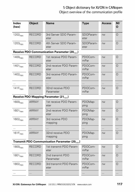
5 Object dictionary for XI/ON in CANopen
Object overview of the communication profile
1202hex RECORD 3rd Server SDO Param-eter
SDOParam-eter
rw O
1203hex RECORD 4th Server SDO Param-eter
SDOParam-eter
rw O
Receive PDO Communication Parameter (20hex)
1400hex RECORD 1st receive PDO Param-eter
PDOCom-mPar
rw O
1401hex RECORD 2nd receive PDO Param-eter
PDOCom-mPar
rw O
1402hex RECORD 3rd receive PDO Param-eter
PDOCom-mPar
rw O
... ... ... ... ... ...
141Fhex RECORD 32nd receive PDO Parameter
PDOCom-mPar
rw O
Receive PDO Mapping Parameter (21hex)
1600hex ARRAY 1st receive PDO Param-eter
PDOMap-ping
rw O
1601hex ARRAY 2nd receive PDO Param-eter
PDOMap-ping
rw O
1602hex ARRAY 3rd receive PDO mapping
PDOMap-ping
rw O
... ... ... ... ... ...
161Fhex ARRAY 32nd receive PDO mapping
PDOMap-ping
rw O
Transmit PDO Communication Parameter (20hex)
1800hex RECORD 1st transmit PDO Param-eter
PDOCom-mPar
rw O
1801hex RECORD 2nd transmit PDO Parameter
PDOCom-mPar
rw O
1802hex RECORD 3rd transmit PDO Param-eter
PDOCom-mPar
rw O
... ... ... ... ... ...
Index (hex)
Object Name Type Access M/O
XI/ON: Gateways for CANopen 10/2011 MN05002005Z-EN www.eaton.com 117
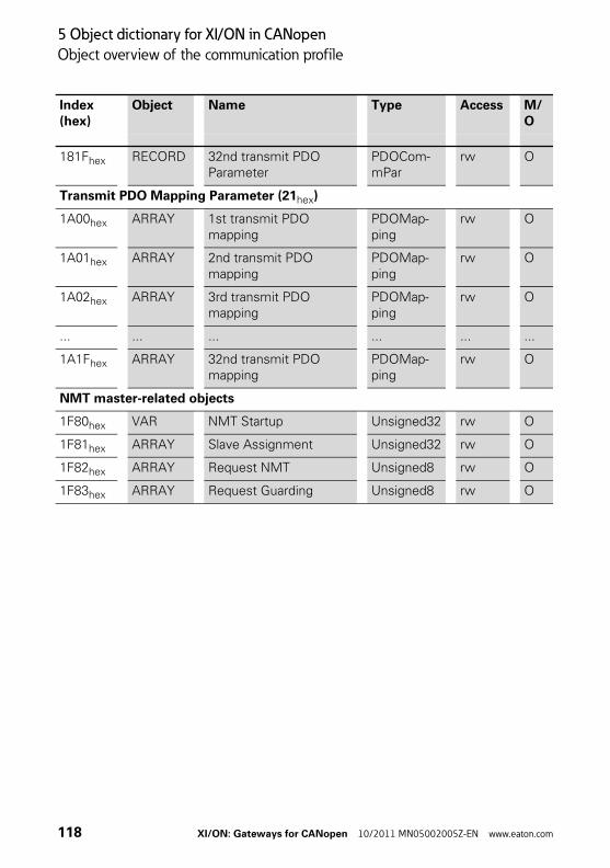
5 Object dictionary for XI/ON in CANopen
Object overview of the communication profile
181Fhex RECORD 32nd transmit PDO Parameter
PDOCom-mPar
rw O
Transmit PDO Mapping Parameter (21hex)
1A00hex ARRAY 1st transmit PDO mapping
PDOMap-ping
rw O
1A01hex ARRAY 2nd transmit PDO mapping
PDOMap-ping
rw O
1A02hex ARRAY 3rd transmit PDO mapping
PDOMap-ping
rw O
... ... ... ... ... ...
1A1Fhex ARRAY 32nd transmit PDO mapping
PDOMap-ping
rw O
NMT master-related objects
1F80hex VAR NMT Startup Unsigned32 rw O
1F81hex ARRAY Slave Assignment Unsigned32 rw O
1F82hex ARRAY Request NMT Unsigned8 rw O
1F83hex ARRAY Request Guarding Unsigned8 rw O
Index (hex)
Object Name Type Access M/O
118 XI/ON: Gateways for CANopen 10/2011 MN05002005Z-EN www.eaton.com

5 Object dictionary for XI/ON in CANopen
Object overview of the communication profile
The column Index (hex) describes the position of the entry in the Object Dictionary.
The object column indicates the type of object.
The Name column shows a predefined symbolic name for the entry.
The Type column shows the data type of the entry predefined in CiA DS-301.
The Access column shows the access possibilities to the entry. These are as follows:
• rw (read/write) = write and reason
• ro (read only) = read only
• wo (write only) = write only
• const (constant) = constant / read only
The column M/O indicates whether the entry is mandatory or optional.
XI/ON: Gateways for CANopen 10/2011 MN05002005Z-EN www.eaton.com 119
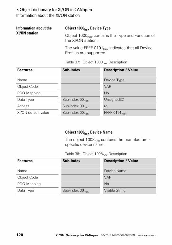
5 Object dictionary for XI/ON in CANopen
Information about the XI/ON station
Information about the XI/ON station
Object 1000hex Device Type
Object 1000hex contains the Type and Function of the XI/ON station.
The value FFFF 0191hex indicates that all Device Profiles are supported.
Table 37: Object 1000hex Description
Object 1008hex Device Name
The object 1008hex contains the manufacturer-specific device name.
Table 38: Object 1008hex Description
Features Sub-index Description / Value
Name Device Type
Object Code VAR
PDO Mapping No
Data Type Sub-index 00hex Unsigned32
Access Sub-index 00hex ro
XI/ON default value Sub-index 00hex FFFF 0191hex
Features Sub-index Description / Value
Name Device Name
Object Code VAR
PDO Mapping No
Data Type Sub-index 00hex Visible String
120 XI/ON: Gateways for CANopen 10/2011 MN05002005Z-EN www.eaton.com

5 Object dictionary for XI/ON in CANopen
Information about the XI/ON station
Object 1009hex Manufacturer Hardware Version
The object 1009hex contains the designation for the Hardware Version.
Table 39: Object 1009hex Description
Access Sub-index 00hex ro
XI/ON default value Sub-index 00hex XN-GW-CANopen (with EDS file XN225163Vxxx)XN-GWBR-CANopen (with EDS file XN270325Vxxx)XNE-GWBR-CANopen (with EDS file XNE107591Vxxx)
Features Sub-index Description / Value
Features Sub-index Description / Value
Name Manufacturer Hardware Version
Object Code VAR
PDO Mapping No
Data Type Sub-index 00hex Visible String
Access Sub-index 00hex ro
XI/ON default value Sub-index 00hex X/00 (XN-GW-CANopen)X/01 (XN-GWBR-CANopen)X/02 (XNE-GWBR-CANopen)
→ The value description corresponds to the state as delivered at the time this Product Description was printed.
XI/ON: Gateways for CANopen 10/2011 MN05002005Z-EN www.eaton.com 121
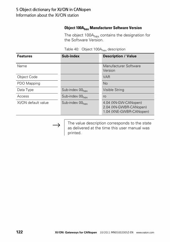
5 Object dictionary for XI/ON in CANopen
Information about the XI/ON station
Object 100Ahex Manufacturer Software Version
The object 100Ahex contains the designation for the Software Version.
Table 40: Object 100Ahex description
Features Sub-index Description / Value
Name Manufacturer Software Version
Object Code VAR
PDO Mapping No
Data Type Sub-index 00hex Visible String
Access Sub-index 00hex ro
XI/ON default value Sub-index 00hex 4.04 (XN-GW-CANopen)2.04 (XN-GWBR-CANopen)1.04 (XNE-GWBR-CANopen)
→ The value description corresponds to the state as delivered at the time this user manual was printed.
122 XI/ON: Gateways for CANopen 10/2011 MN05002005Z-EN www.eaton.com
5 Object dictionary for XI/ON in CANopen
Information about the XI/ON station
Object 1018hex Identity Object
The object 1018hex contains the general informa-tion about the XI/ON gateway.
The Vendor-ID (Sub-index 01hex) is a unique ID which precisely identifies the manufacturer. The manufacturer-specific Product Code (Sub-index 02hex) identifies a specific device version. The manufacturer-specific Revision Number (Sub-index 03hex) consists of a main revision number and a sub-revision number. The main revision number defines a special CANopen functionality. If the CANopen functionality is expanded, then the main revision number must be incremented. The sub-revision number identifies various versions that have the same CANopen functionality.
XI/ON: Gateways for CANopen 10/2011 MN05002005Z-EN www.eaton.com 123
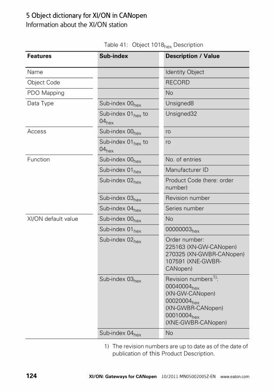
5 Object dictionary for XI/ON in CANopen
Information about the XI/ON station
Table 41: Object 1018hex Description
1) The revision numbers are up to date as of the date of publication of this Product Description.
Features Sub-index Description / Value
Name Identity Object
Object Code RECORD
PDO Mapping No
Data Type Sub-index 00hex Unsigned8
Sub-index 01hex to 04hex
Unsigned32
Access Sub-index 00hex ro
Sub-index 01hex to 04hex
ro
Function Sub-index 00hex No. of entries
Sub-index 01hex Manufacturer ID
Sub-index 02hex Product Code (here: order number)
Sub-index 03hex Revision number
Sub-index 04hex Series number
XI/ON default value Sub-index 00hex No
Sub-index 01hex 00000003hex
Sub-index 02hex Order number:225163 (XN-GW-CANopen)270325 (XN-GWBR-CANopen)107591 (XNE-GWBR-CANopen)
Sub-index 03hex Revision numbers1):00040004hex (XN-GW-CANopen)00020004hex (XN-GWBR-CANopen)00010004hex (XNE-GWBR-CANopen)
Sub-index 04hex No
124 XI/ON: Gateways for CANopen 10/2011 MN05002005Z-EN www.eaton.com

5 Object dictionary for XI/ON in CANopen
Information about the XI/ON station
Table 42: Bit structure for the revision number
msb lsb
31 15 0
Main revision number Sub-revision number
XI/ON: Gateways for CANopen 10/2011 MN05002005Z-EN www.eaton.com 125

5 Object dictionary for XI/ON in CANopen
Information about the XI/ON station
Object 1020hex Verify Configuration
The object 1020hex is used for checking the station configuration after a device reset.
The XI/ON-CANopen gateway supports the non-volatile storage of parameters. A network configu-ration tool or a CANopen Manager can use object 1020hex to test the station configuration after a reset, and so check whether a reconfiguration is necessary. The configuration tool saves the time and date simultaneously in object 1020hex and the corresponding DCF file. After a reset, the most recent configuration and the signature will be restored, either automatically or on request. If the configuration values are altered by some other command, then the object will be set to 0.
The Configuration Manager compares the signa-ture and the configuration with the values from the DCF file. If it discovers any deviations, a reconfig-uration will be necessary.
126 XI/ON: Gateways for CANopen 10/2011 MN05002005Z-EN www.eaton.com
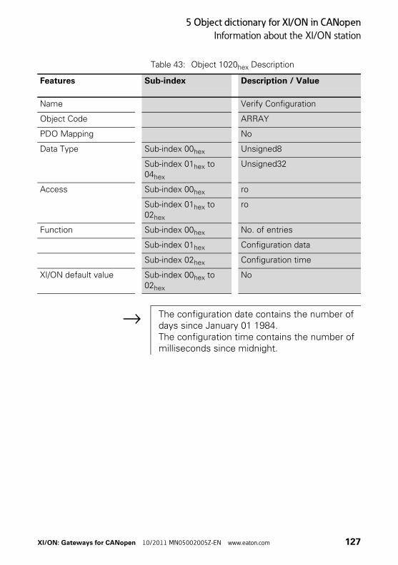
5 Object dictionary for XI/ON in CANopen
Information about the XI/ON station
Table 43: Object 1020hex Description
Features Sub-index Description / Value
Name Verify Configuration
Object Code ARRAY
PDO Mapping No
Data Type Sub-index 00hex Unsigned8
Sub-index 01hex to 04hex
Unsigned32
Access Sub-index 00hex ro
Sub-index 01hex to 02hex
ro
Function Sub-index 00hex No. of entries
Sub-index 01hex Configuration data
Sub-index 02hex Configuration time
XI/ON default value Sub-index 00hex to 02hex
No
→ The configuration date contains the number of days since January 01 1984.The configuration time contains the number of milliseconds since midnight.
XI/ON: Gateways for CANopen 10/2011 MN05002005Z-EN www.eaton.com 127

5 Object dictionary for XI/ON in CANopen
Information about the XI/ON station
Object 1027hex Module List
The object 1027hex describes all the currently installed modules in a XI/ON station.
Table 44: Object 1027hex Description
The sequential Sub-indices 01hex ≦ nh ≦ 4Ahex (74 dec) describe the corresponding XI/ON modules in the order in which they are installed in the XI/ON station. Each entry contains a number that identi-fies the particular module.
The EDS file contains the individual extensions of object 1027hex (e.g. M1SubExt1027) for all the optional XI/ON module types listed in the section [SupportedModules]. The default values (e.g. DefaultValue=0x8000) correspond to the identi-fiers for the particular module types (e.g.[M1ModuleInfo]ProductName=Generic XN-BR/-PF).
Features Sub-index Description / Value
Name Module List
Object Code ARRAY
PDO Mapping No
Data Type Sub-index 00hex Unsigned8
Sub-index 01hex to 4Ahex Unsigned16
Function Sub-index 00hex Number of modules in this station
Sub-index 01hex to 4Ahex Identifier for the modules of the station (max. 74)
Access Sub-index 00hex ro
XI/ON default value Sub-index 00hex No
→ One identifier exists for each type of XI/ON module.
128 XI/ON: Gateways for CANopen 10/2011 MN05002005Z-EN www.eaton.com

5 Object dictionary for XI/ON in CANopen
Error Register
Error Register Object 1001hex Error Register
The object 1001hex Error Register contains the Error Register for the XI/ON-CANopen gateway. It thus contains in one byte the internal errors that occur.
Table 45: Object 1001hex Description
Features Sub-index Description / Value
Name Error Register
Object Code VAR
PDO Mapping Yes
Data Type Sub-index 00hex Unsigned8
Access Sub-index 00hex ro
XI/ON default value Sub-index 00hex No
Error Register
Bit 0 Bit 1 Bit 2 Bit 3 Bit 4 Bit 5 Bit 6 Bit 7
generic Current Voltage 0 Comm. 0 0 Manu.
Abbreviations I/O module type
generic General error all
Current Output short-circuit/current error
DO, AI,THERMO
Voltage Voltage error BR, PF, DO, AI, AO
Comm. Communication error all
Manu. Manufacturer specific error all
XI/ON: Gateways for CANopen 10/2011 MN05002005Z-EN www.eaton.com 129
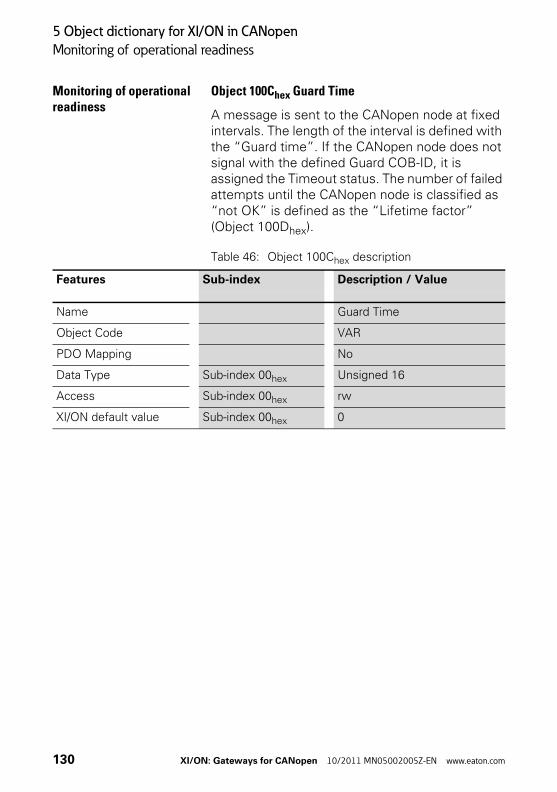
5 Object dictionary for XI/ON in CANopen
Monitoring of operational readiness
Monitoring of operational readiness
Object 100Chex Guard Time
A message is sent to the CANopen node at fixed intervals. The length of the interval is defined with the “Guard time”. If the CANopen node does not signal with the defined Guard COB-ID, it is assigned the Timeout status. The number of failed attempts until the CANopen node is classified as “not OK” is defined as the “Lifetime factor” (Object 100Dhex).
Table 46: Object 100Chex description
Features Sub-index Description / Value
Name Guard Time
Object Code VAR
PDO Mapping No
Data Type Sub-index 00hex Unsigned 16
Access Sub-index 00hex rw
XI/ON default value Sub-index 00hex 0
130 XI/ON: Gateways for CANopen 10/2011 MN05002005Z-EN www.eaton.com
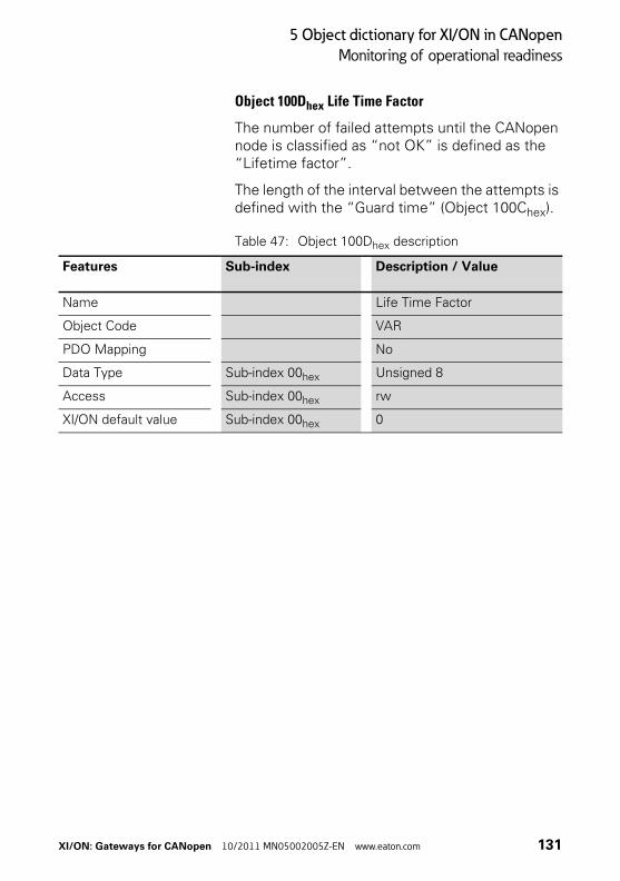
5 Object dictionary for XI/ON in CANopen
Monitoring of operational readiness
Object 100Dhex Life Time Factor
The number of failed attempts until the CANopen node is classified as “not OK” is defined as the “Lifetime factor”.
The length of the interval between the attempts is defined with the “Guard time” (Object 100Chex).
Table 47: Object 100Dhex description
Features Sub-index Description / Value
Name Life Time Factor
Object Code VAR
PDO Mapping No
Data Type Sub-index 00hex Unsigned 8
Access Sub-index 00hex rw
XI/ON default value Sub-index 00hex 0
XI/ON: Gateways for CANopen 10/2011 MN05002005Z-EN www.eaton.com 131

5 Object dictionary for XI/ON in CANopen
Monitoring of operational readiness
Object 1016hex Consumer Heartbeat Time
The Heartbeat Protocol is used to monitor the operational readiness of other CANopen bus nodes.
The failure of a CANopen node can be registered by all stations.
Object 1016hex defines the cycle time (interval) at which the Heartbeat is expected.
A device generates the Heartbeat with a specific cycle time (see object 1017hex “Producer Heart-beat Time”). Another device receives the Heart-beat and monitors the cycle time.
This cycle time should be longer than the corre-sponding cycle time for the transmitter (see object 1017hex). The monitoring of the Heartbeat starts when the first Heartbeat Frame is received.If the Consumer Heartbeat Time = 0, then the corresponding entry will not be used.
The time is set as a multiple of 1 ms.
The Heartbeat Protocol must be seen as an alter-native to Node/Life Guarding, which, unlike Guarding, does not use Remote Frames.
132 XI/ON: Gateways for CANopen 10/2011 MN05002005Z-EN www.eaton.com
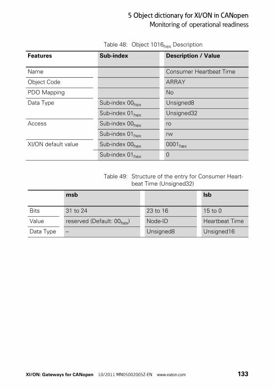
5 Object dictionary for XI/ON in CANopen
Monitoring of operational readiness
Table 48: Object 1016hex Description
Table 49: Structure of the entry for Consumer Heart-beat Time (Unsigned32)
Features Sub-index Description / Value
Name Consumer Heartbeat Time
Object Code ARRAY
PDO Mapping No
Data Type Sub-index 00hex Unsigned8
Sub-index 01hex Unsigned32
Access Sub-index 00hex ro
Sub-index 01hex rw
XI/ON default value Sub-index 00hex 0001hex
Sub-index 01hex 0
msb lsb
Bits 31 to 24 23 to 16 15 to 0
Value reserved (Default: 00hex) Node-ID Heartbeat Time
Data Type – Unsigned8 Unsigned16
XI/ON: Gateways for CANopen 10/2011 MN05002005Z-EN www.eaton.com 133
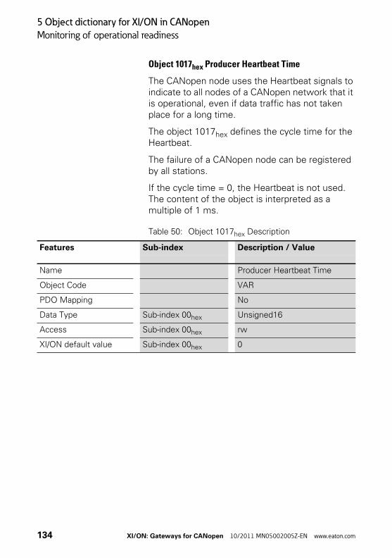
5 Object dictionary for XI/ON in CANopen
Monitoring of operational readiness
Object 1017hex Producer Heartbeat Time
The CANopen node uses the Heartbeat signals to indicate to all nodes of a CANopen network that it is operational, even if data traffic has not taken place for a long time.
The object 1017hex defines the cycle time for the Heartbeat.
The failure of a CANopen node can be registered by all stations.
If the cycle time = 0, the Heartbeat is not used. The content of the object is interpreted as a multiple of 1 ms.
Table 50: Object 1017hex Description
Features Sub-index Description / Value
Name Producer Heartbeat Time
Object Code VAR
PDO Mapping No
Data Type Sub-index 00hex Unsigned16
Access Sub-index 00hex rw
XI/ON default value Sub-index 00hex 0
134 XI/ON: Gateways for CANopen 10/2011 MN05002005Z-EN www.eaton.com

5 Object dictionary for XI/ON in CANopen
“Store/Load Parameters” commands
“Store/Load Parameters” commands
Parameter changes that are made through SDO access are only stored in volatile memory. All alter-ations that are made by the user will be replaced by default values at the next Reset Communica-tion, Reset Node or Power-ON Boot-Up.
With XI/ON, it is possible to use a command to make a permanent save of the communication and/or application parameters. This is done through the “Store Parameters” command (Object 1010hex Sub-index 1 to 3). The command is executed by using an SDO to write the data contents 6576 6173hex (“save”) to one of the following entries:
• 1010hex Sub-index 1 saves all parameters
• 1010hex Sub-index 2 saves all communication parameters
• 1010hex Sub-index 3 saves all device parameters
(see CiA DS-301 V4.01)
Table 51: Data contents 6576 6173hex (“save”)
Since in some circumstances it may not be possible to restore the original memory contents after a lot of alterations, XI/ON supports the “Restore Default Parameter” command (Object 1011hex Sub-index 1 to 3) with the following data contents: 6461 6F6Chex (“load”).
msb lsb
ASCII e v a s
HEX 65hex 76hex 61hex 73hex
XI/ON: Gateways for CANopen 10/2011 MN05002005Z-EN www.eaton.com 135

5 Object dictionary for XI/ON in CANopen
“Store/Load Parameters” commands
Table 52: Data contents 6461 6F6Chex (“load”)
The division of the sub-entries corresponds to that for the “Store Parameters” command.
After the command “Restore Default Parame-ters”, a Reset Node must be executed, followed by a “Store Parameters” command. The default values are only saved again when this last command is executed.
msb lsb
ASCII d a O l
HEX 64hex 61hex 6Fhex 6Chex
136 XI/ON: Gateways for CANopen 10/2011 MN05002005Z-EN www.eaton.com

5 Object dictionary for XI/ON in CANopen
“Store/Load Parameters” commands
Object 1010hex Store Parameters
The object 1010hex can be used to store param-eter changes in non-volatile memory. The command is executed by writing the data contents 6576 6173hex (“save”) to the sub-index with the required function.
Table 53: Object 1010hex Description
Features Sub-index Description / Value
Name Store Parameters
Object Code ARRAY
PDO Mapping No
Data Type Sub-index 00hex Unsigned8
Sub-index 01hex to 03hex
Unsigned32
Access Sub-index 00hex ro
Sub-index 01hex to 03hex
rw
Function Sub-index 01hex Store all parameters
Sub-index 02hex Store the communication parameters
Sub-index 03hex Store the application parame-ters
XI/ON default value Sub-index 00hex 3
Sub-index 01hex to 03hex
00000001hex
XI/ON: Gateways for CANopen 10/2011 MN05002005Z-EN www.eaton.com 137

5 Object dictionary for XI/ON in CANopen
“Store/Load Parameters” commands
Object 1011hex Restore Default Parameters
Object 1011hex can be used to restore the default parameters. The command is executed by writing the data contents 6461 6F6Chex (“load”) to the sub-index with the required function.
Table 54: Object 1011hex Description
Features Sub-index Description / Value
Name Restore Default Parameters
Object Code ARRAY
PDO Mapping No
Data Type Sub-index 00hex Unsigned8
Sub-index 01hex to 03hex
Unsigned32
Access Sub-index 00hex ro
Sub-index 01hex to 03hex
rw
Function Sub-index 01hex Restore all parameters
Sub-index 02hex Restore the communication parameters
Sub-index 03hex Restore the application param-eters
XI/ON default value Sub-index 00hex 3
Sub-index 01hex to 03hex
00000001hex
138 XI/ON: Gateways for CANopen 10/2011 MN05002005Z-EN www.eaton.com

5 Object dictionary for XI/ON in CANopen
Identifiers of Synchronization and Emergency
Identifiers of Synchroniza-tion and Emergency
Object 1005hex Sync COB-ID
The object 1005hex defines the COB-ID and thus the priority (→ Chapter “Identifier for the standard objects“, Page 77) of the Synchronization object (SYNC). The XI/ON-CANopen gateway cannot generate SYNC messages, only receive them. The reception of a synchronization message initiates the transfer of the process data simultaneously for all recipients. In this way, outputs can be set simul-taneously or inputs read in parallel.
Table 55: Object 1005hex Description
Table 56: Structure of the SYNC COB-ID entry (Unsigned32)
1) XI/ON
Features Sub-index Description / Value
Name SYNC COB-ID
Object Code VAR
PDO Mapping No
Data Type Sub-index 00hex Unsigned32
Access Sub-index 00hex rw
XI/ON default value Sub-index 00hex 0000 0080hex
msb lsb
Bits 31 30 29 28 to 11 10 to 0
11-bit ID1) X 0 0 00 0000 0000 0000 0000
0001000000011-bit Identifier
29-bit ID X 0 1 29-bit Identifier
XI/ON: Gateways for CANopen 10/2011 MN05002005Z-EN www.eaton.com 139

5 Object dictionary for XI/ON in CANopen
Identifiers of Synchronization and Emergency
Table 57: Description of the SYNC COB-ID entry
1) XI/ON
Object 1014hex Emcy COB-ID
Object 1014hex contains the identifier for the Emergency messages (→ Chapter “Identifier for the standard objects“, Page 77).
Table 58: Object 1014hex Description
Bit number Value Description
31 (MSB) X fixed
30 01)
1Module does not generate a SYNC messageModule generates SYNC message
29 01)
111-bit ID (CAN 2.0A)29-bit ID (CAN 2.0B)
28 to 11 0X
if Bit 29 = 0 if Bit 29 = 1: Bits 28 to 11 of the SYNC-COB-ID
10 to 0 (lsb) X Bit 10 to 0 of the SYNC-COB-ID
→ Bit 30 is static, i.e. cannot be changed.
Features Sub-index Description / Value
Name Emcy COB-ID
Object Code VAR
PDO Mapping No
Data Type Sub-index 00hex Unsigned32
Access Sub-index 00hex rw
XI/ON default value Sub-index 00hex 0000 0080hex+Node-ID
140 XI/ON: Gateways for CANopen 10/2011 MN05002005Z-EN www.eaton.com

5 Object dictionary for XI/ON in CANopen
Identifiers of Synchronization and Emergency
Table 59: Structure of the Emcy COB-ID entry (Unsigned32)
Table 60: Description of the Emcy COB-ID entry
msb lsb
Bits 31 30 29 28 to 11 10 to 0
11-bit ID 0/1 0 0 00 0000 0000 0000 0000
11-bit Identifier
29-bit ID 0/1 0 1 29-bit Identifier
Bit number Value Description
31 (MSB) 01
EMCY exists / is validEMCY does not exist / is not valid
30 0 reserved (always 0)
29 01
1-bit ID (CAN 2.0A) → for XI/ON29-bit ID (CAN 2.0B)
28 to 11 0X
if Bit 29 = 0 if Bit 29 = 1: Bits 28 to 11 of the 29-bit-COB-ID
10 to 0 (LSB) X Bit 10 to 0 of the COB-ID
→ Bit 30 is static, i.e. cannot be changed.
XI/ON: Gateways for CANopen 10/2011 MN05002005Z-EN www.eaton.com 141

5 Object dictionary for XI/ON in CANopen
Transfer of service data
Transfer of service data Objects 1200hex to 1203hex Server SDO Parameters
The objects 1200hex to 1203hex define the priority for the transfer of SDO1 to SDO4.
The priority of the data is defined by the identi-fier/COB-ID.
Table 61: Object 1200hex to 1203hex Description
Features Sub-index Description / Value
Name Server SDO Parameter
Object Code RECORD
PDO Mapping No
Data Type Sub-index 00hex Unsigned8
Sub-index 01hex Unsigned32
Sub-index 02hex Unsigned32
Function Sub-index 00hex No. of entries
Sub-index 01hex COB-ID Client->Server
Sub-index 02hex COB-ID Server->Client
Access Sub-index 00hex ro
Sub-index 01hex • ro:Object 1200hex
• rw:Object 1201hex to Object 1203hex
Sub-index 02hex • ro:Object 1200hex
• rw:Object 1201hex to Object 1203hex
142 XI/ON: Gateways for CANopen 10/2011 MN05002005Z-EN www.eaton.com

5 Object dictionary for XI/ON in CANopen
Transfer of service data
XI/ON default value Sub-index 00hex 2
Sub-index 01hex • Node ID + 00000600hex:Object 1200hex
• No:Object 1201hex to Object 1203hex
Sub-index 02hex • Node ID + 00000580hex:Object 1200hex
• No:Object 1201hex to Object 1203hex
Features Sub-index Description / Value
XI/ON: Gateways for CANopen 10/2011 MN05002005Z-EN www.eaton.com 143

5 Object dictionary for XI/ON in CANopen
Transfer of process output data
Transfer of process output data
The objects 1400hex to 141Fhex define together with objects 1600hex to 161Fhex which output data with which priority and with which transmission type are to be transferred with the RPDO transfer.
The object 1400hex defines the priority and the transmission type for the RPDO1. The object 1600hex states the object index, sub-index and the data length for the data to be transferred with RPDO1.
The object 1401hex together with object 1601hex provides this information accordingly for the RPDO2 etc.
The priority of the data is defined by the identi-fier/COB-ID.
For objects 1400hex to 1403hex and 1600hex to 1603hex the values are already entered by default.
A station with up to 64 digital outputs and 12 analog outputs therefore transfers the process output data automatically via RPDOs.
144 XI/ON: Gateways for CANopen 10/2011 MN05002005Z-EN www.eaton.com

5 Object dictionary for XI/ON in CANopen
Transfer of process output data
Objects 1400hex to 141Fhex Receive PDO Parameters
The objects 1400hex to 141Fhex define the priority and the transmission type for the RPDO1 to RPDDO32.
The priority is defined with the identifier/COB-ID (→ Chapter “Identifier for the standard objects“, Page 77) via the sub-index 01hex. The remaining content can be defined as invalid/valid with the most significant bit of sub-index 01hex. The corre-sponding most significant hexadecimal number is then >8.
The transmission type is defined with the sub-index 02hex. Possible transmission types are shown in Table 65, Page 148.
Which data content is to be transferred with the RPDO1 to RPDO32 is defined with the objects 1600hex to 161Fhex .
XI/ON: Gateways for CANopen 10/2011 MN05002005Z-EN www.eaton.com 145

5 Object dictionary for XI/ON in CANopen
Transfer of process output data
Table 62: Object 1400hex to 141Fhex Description
Features Sub-index Description / Value
Name Receive PDO Parameters
Object Code RECORD
PDO Mapping No
Data Type Sub-index 00hex Unsigned8
Sub-index 01hex Unsigned32
Sub-index 02hex Unsigned8
Function Sub-index 00hex No. of entries
Sub-index 01hex PDO COB-ID (→ Chapter “Identifier for the standard objects“, Page 77)
Sub-index 02hex Transmission Type (→ Table 65, Page 148)
Access Sub-index 00hex ro
Sub-index 01hex rw
Sub-index 02hex rw
XI/ON default value Sub-index 00hex 02hex
Sub-index 01hex • Node ID + 00000200hex:Object 1400hex
• Node ID + 00000300hex:Object 1401hex
• Node ID + 00000400hex:Object 1402hex
• Node ID + 00000500hex:Object 1403hex
• Node ID + 80000XXXhex:Object 1404hex to 140Fhex:The identifiers are provided but not enabled
• 80000000hex:Object 140Fhex to 141Fhex
Sub-index 02hex FFhex (255)
146 XI/ON: Gateways for CANopen 10/2011 MN05002005Z-EN www.eaton.com
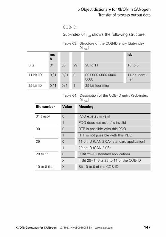
5 Object dictionary for XI/ON in CANopen
Transfer of process output data
COB-ID:
Sub-index 01hex shows the following structure:
Table 63: Structure of the COB-ID entry (Sub-index 01hex)
Table 64: Description of the COB-ID entry (Sub-index 01hex)
msb
lsb
Bits 31 30 29 28 to 11 10 to 0
11-bit ID 0 / 1 0 / 1 0 00 0000 0000 0000 0000
11-bit Identi-fier
29-bit ID 0 / 1 0 / 1 1 29-bit Identifier
Bit number Value Meaning
31 (msb) 0 PDO exists / is valid
1 PDO does not exist / is invalid
30 0 RTR is possible with this PDO
1 RTR is not possible with this PDO
29 0 11-bit ID (CAN 2.0A) (standard application)
1 29-bit ID (CAN 2.0B)
28 to 11 0 If Bit 29=0 (standard application)
X If Bit 29=1: Bits 28 to 11 of the COB-ID
10 to 0 (lsb) X Bit 10 to 0 of the COB-ID
XI/ON: Gateways for CANopen 10/2011 MN05002005Z-EN www.eaton.com 147

5 Object dictionary for XI/ON in CANopen
Transfer of process output data
Transmission type:
Sub-index 02hex can assume the following struc-ture:
Table 65: Description of transmission type
Value PDO transmission
cyclic acyclic synchro-nous
asyn-chronous
only with RTR
0 X X
1 X X
2 to 254 reserved
255 X
148 XI/ON: Gateways for CANopen 10/2011 MN05002005Z-EN www.eaton.com

5 Object dictionary for XI/ON in CANopen
Transfer of process output data
Objects 1600hex to 161Fhex Receive PDO Mapping Parameters
The objects 1600hex to 161Fhex state which data content is to be transferred with the RPDO1 to RPDO32. The data content itself (in this case: process output data) is represented with product-specific, mappable objects.
→ Chapter “Mappable objects“, Page 107.
The process output data for the digital channels is entered, for example, in the objects 6200hex, 6220hex etc.
These objects are described in the respective user manuals.
The entry in the sub-index 01hex to 40hex of the objects 1600hex to 161Fhex comprises the object number, the sub-index and the length of the data content which is to be transferred with the respec-tive RPDO.
An RPDO can transfer up to 8 bytes (64 bits).
The number of sub-indices depends on the data length and must be calculated and entered by the user for larger projects (see below).
Eight sub-indices are required for a data length of 8 bits, in order to represent a total of 64 bits. A data length of 1 bit requires 64 sub-indices for a total of 64 bits.
Object 1600hex to 1603hex (RPDO1 to RPDO4) references by default the values for the first 64 digital output channels and the values for the first 12 analog output channels. This requires the values to be represented with the object 6200hex (digital values) and the object 6411hex (analog values).
XI/ON: Gateways for CANopen 10/2011 MN05002005Z-EN www.eaton.com 149

5 Object dictionary for XI/ON in CANopen
Transfer of process output data
Table 66: Object 1600hex to 161Fhex Description
Features Sub-index Description / Value
Name Receive PDO Mapping Param-eters
Object Code RECORD
PDO Mapping No
Data Type Sub-index 00hex Unsigned8
Sub-index 01hex toSub-index 40hex
Unsigned32
Function
1600hex to 1603hex → Table 67, Page 151
1604hex to 161Fhex Sub-index 00hex Number of entries (depending on the data length)
Sub-index 01hex 1st Mapped Application Object
Sub-index 02hex 2nd Mapped Application Object
Sub-index 03hex 3rd Mapped Application Object
... ...
Sub-index 40hex 64th Mapped Application Object
Access Sub-index 00hex rw
Sub-index 01hex toSub-index 08hex
rw
XI/ON default value
1600hex to 1603hex → Table 67, Page 151
1604hex to 161Fhex Sub-index 00hex to Sub-index 40hex
No
→ The number of mapping objects, which are auto-matically generated by the gateway during start-up, depends on the actual physical structure of the XI/ON station.
150 XI/ON: Gateways for CANopen 10/2011 MN05002005Z-EN www.eaton.com
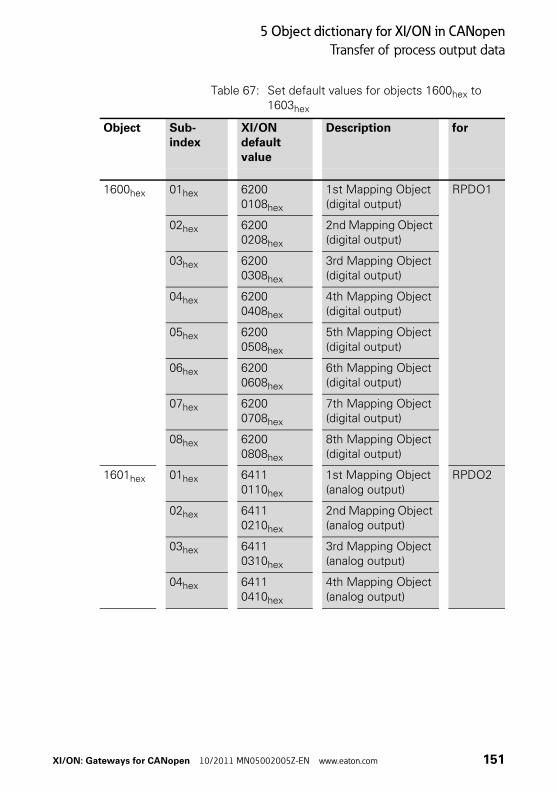
5 Object dictionary for XI/ON in CANopen
Transfer of process output data
Table 67: Set default values for objects 1600hex to 1603hex
Object Sub-index
XI/ON default value
Description for
1600hex 01hex 6200 0108hex
1st Mapping Object (digital output)
RPDO1
02hex 6200 0208hex
2nd Mapping Object (digital output)
03hex 6200 0308hex
3rd Mapping Object (digital output)
04hex 6200 0408hex
4th Mapping Object (digital output)
05hex 6200 0508hex
5th Mapping Object (digital output)
06hex 6200 0608hex
6th Mapping Object (digital output)
07hex 6200 0708hex
7th Mapping Object (digital output)
08hex 6200 0808hex
8th Mapping Object (digital output)
1601hex 01hex 6411 0110hex
1st Mapping Object (analog output)
RPDO2
02hex 6411 0210hex
2nd Mapping Object (analog output)
03hex 6411 0310hex
3rd Mapping Object (analog output)
04hex 6411 0410hex
4th Mapping Object (analog output)
XI/ON: Gateways for CANopen 10/2011 MN05002005Z-EN www.eaton.com 151

5 Object dictionary for XI/ON in CANopen
Transfer of process output data
The following structure is used for the parameters of the sub-indices 01hex to 40hex:
Table 68: Structure of the PDO mapping entries
1602hex 01hex 6411 0510hex
1st Mapping Object (analog output)
RPDO3
02hex 6411 0610hex
2nd Mapping Object (analog output)
03hex 6411 0710hex
3rd Mapping Object (analog output)
04hex 6411 0810hex
4th Mapping Object (analog output)
1603hex 01hex 6411 0910hex
1st Mapping Object (analog output)
RPDO4
02hex 6411 0A10hex
2nd Mapping Object (analog output)
03hex 6411 0B10hex
3rd Mapping Object (analog output)
04hex 6411 0C10hex
4th Mapping Object (analog output)
Object Sub-index
XI/ON default value
Description for
msb lsb
Object-index (16 bit)
Sub-index (8 bit) Object length (8 bit)
→ Observe the instructions given in Chapter “Procedure for altering PDO mappings“, Page 109 for changing the number of mapping entries.
152 XI/ON: Gateways for CANopen 10/2011 MN05002005Z-EN www.eaton.com

5 Object dictionary for XI/ON in CANopen
Transfer of process input data
Transfer of process input data
The objects 1800hex to 181Fhex define together with objects 1A00hex to 1A1Fhex which output data with which priority and with which transmis-sion type are to be transferred with the TPDO transfer.
The object 1800hex defines the priority, the Inhibit Time, the maximum interval (Event Time) between two transmissions and the transmission type for the TPDO1. The object 1A00hex states the object index, sub-index and the data length for the data to be transferred with TPDO1.
The object 1801hex together with object 1A01hex provides this information accordingly for the TPDO2 etc.
The priority of the data is defined by the identi-fier/COB-ID.
The values are already entered by default for objects 1800hex to 1803hex and 1A00hex to 1A03hex .
A station with up to 64 digital inputs and 12 analog inputs therefore transfers the process input data automatically via TPDOs.
XI/ON: Gateways for CANopen 10/2011 MN05002005Z-EN www.eaton.com 153

5 Object dictionary for XI/ON in CANopen
Transfer of process input data
Objects 1800hex to 181Fhex Transmit PDO Parameters
The objects 1800hex to 181F hex define the priority, the Inhibit Time, the maximum interval (Event Time) between two transmissions and the trans-mission type for TPDO1 to TPDO32.
The priority is defined with the identifier/COB-ID (→ Chapter “Identifier for the standard objects“, Page 77) via the sub-index 01hex. The remaining content can be defined as invalid/valid with the most significant bit of sub-index 01hex. The corre-sponding most significant hexadecimal number is then >8.
The transmission type is defined with the sub-index 02hex. Possible transmission types are shown in Table 65, Page 148.
The minimum inhibit time is defined with the sub-index 03hex.
The maximum interval (Event Time) between two transmissions is defined with sub-index 05hex.
Which data content is to be transferred with the RPDO1 to RPDO32 is defined with the objects 1A00hex to 1A1Fhex.
154 XI/ON: Gateways for CANopen 10/2011 MN05002005Z-EN www.eaton.com

5 Object dictionary for XI/ON in CANopen
Transfer of process input data
Table 69: Object 1800hex to 181Fhex Description
Features Sub-index Description / Value
Name Transmit PDO Communication Parameters
Object Code RECORD
PDO Mapping No
Parameter name Sub-index 00hex Number of Entries
Sub-index 01hex COB-ID (→ Chapter “Identifier for the standard objects“, Page 77)
Sub-index 02hex Transmission Type (→ Table 72, Page 158)
Sub-index 03hex Inhibit Time (→ Chapter “The minimum inhibit time“, Page 158)
Sub-index 04hex Reserved
Sub-index 05hex Event Time (→ Chapter “The maximum interval (Event Time) between two transmissions“, Page 158)
Data Type Sub-index 00hex Unsigned8
Sub-index 01hex Unsigned32
Sub-index 02hex Unsigned8
Sub-index 03hex Unsigned16
Sub-index 04hex Unsigned8
Sub-index 05hex Unsigned16
Access Sub-index 00hex ro
Sub-index 01hex to 05hex
rw
XI/ON: Gateways for CANopen 10/2011 MN05002005Z-EN www.eaton.com 155

5 Object dictionary for XI/ON in CANopen
Transfer of process input data
XI/ON default value Sub-index 00hex 5
Sub-index 01hex • Index 1800hex:0000 0180hex + Node-ID
• Index 1801hex:0000 0280hex + Node-ID
• Index 1802hex:0000 0380hex + Node-ID
• Index 1803hex:0000 0480hex + Node-ID
• Index 1804hex to 181Fhex: Invalid
Sub-index 02hex 255
Sub-index 03hex to 05hex
0000hex
Features Sub-index Description / Value
156 XI/ON: Gateways for CANopen 10/2011 MN05002005Z-EN www.eaton.com

5 Object dictionary for XI/ON in CANopen
Transfer of process input data
The COB-ID:
Sub-index 01hex shows the following structure:
Table 70: Structure of the COB-ID entry (Sub-index 01hex)
Table 71: Description of the COB-ID entry (Sub-index 01hex)
msb lsb
Bits 31 30 29 28 to 11 10 to 0
11-bit ID 0 / 1 0 / 1 0 00 0000 0000 0000 0000
11-bit Identi-fier
29-bit ID 0 / 1 0 / 1 1 29-bit Identifier
Bit number Value Meaning
31 (msb) 0 PDO exists / is valid
1 PDO does not exist / is invalid
30 0 RTR is possible with this PDO
1 RTR is not possible with this PDO
29 0 11-bit ID (CAN 2.0A) (standard application)
1 29-bit ID (CAN 2.0B)
28 to 11 0 If Bit 29=0 (standard application)
X If Bit 29=1: Bits 28 to 11 of the COB-ID
10 to 0 (lsb) X Bit 10 to 0 of the COB-ID
XI/ON: Gateways for CANopen 10/2011 MN05002005Z-EN www.eaton.com 157

5 Object dictionary for XI/ON in CANopen
Transfer of process input data
Transmission type:
Sub-index 02hex can assume the following struc-ture:
Table 72: Description of transmission type
The minimum inhibit timeThe Inhibit Time is defined as the time between two transmissions so that high-priority messages to do not constantly load the bus.The Inhibit Time is defined with sub-index 03hex as the multiple of 100 μs. However, since the time resolution of the system clock in the XI/ON-CANopen gateway is 1 ms, Inhibit Time values below 10 × 100 μs have no effect.
The maximum interval (Event Time) between two transmissionsSub-index 05hex defines the maximum interval after which a TPDO will be transmitted, even though no event has occurred. The expiry of the interval set for the Event Time is detected as an event. If any other event occurs, the Event Time is reset and restarted.The value of the object is interpreted as a multiple of 1 ms.
Transmission type
PDO transmission
cyclic acyclic synchro-nous
asyn-chronous
only with RTR
0 X X
1 X X
2 to 252 reserved
253 X X
254 reserved
255 X
158 XI/ON: Gateways for CANopen 10/2011 MN05002005Z-EN www.eaton.com
5 Object dictionary for XI/ON in CANopen
Transfer of process input data
Objects 1A00hex to 1A1Fhex Transmit PDO Mapping Parameters
The objects 1A00hex to 1A1Fhex state which data content is to be transferred with the TPDO1 to TPDO32. The data content itself (in this case: process input data) is represented with product-specific, mappable objects.
→ Chapter “Mappable objects“, Page 107.
The process input data for the digital channels are entered, for example, in the objects 6000hex, 6020hex etc.
These objects are described in the respective user manuals.
The entry in the sub-index 01hex to 40hex of the objects 1A00hex to 1A1Fhex comprises the object number, the sub-index and the length of the data content which is to be transferred with the respec-tive TPDO.
A TPDO can transfer up to 8 bytes (64 bits).
The number of sub-indices depends on the data length and must be calculated and entered by the user for larger projects (see below).
8 sub-indices are required for a data length of 8 bits in order to represent a total of 64 bits. A data length of 1 bit requires 64 sub-indices for a total of 64 bits.
Object 1A00hex to 1A03hex (TPDO1 to TPDO4) references by default the values for the first 64 digital input channels and the values for the first 12 analog input channels. This requires the values to be represented with the object 6000hex (digital values) and the object 6401hex (analog values).
XI/ON: Gateways for CANopen 10/2011 MN05002005Z-EN www.eaton.com 159

5 Object dictionary for XI/ON in CANopen
Transfer of process input data
Table 73: Object 1A00hex to 1A1Fhex Description
Features Sub-index Description / Value
Name Transmit PDO Mapping Param-eters
Object Code RECORD
PDO Mapping No
Data Type Sub-index 00hex Unsigned8
Sub-index 01hex toSub-index 40hex
Unsigned32
Function
1A00hex to 1A03hex → Table 74, Page 161
1A03hex to 1A1Fhex Sub-index 00hex Number of entries (depending on the data length)
Sub-index 01hex 1st Mapped Application Object
Sub-index 02hex 2nd Mapped Application Object
Sub-index 03hex 3rd Mapped Application Object
... ...
Sub-index 40hex 64th Mapped Application Object
Access Sub-index 00hex rw
Sub-index 01hex toSub-index 08hex
rw
XI/ON default value
1A00hex to 1A03hex → Table 74, Page 161
1A04hex to 1A1Fhex Sub-index 00hex to Sub-index 40hex
No
→ The number of mapping objects, which are auto-matically generated by the gateway during start-up, depends on the actual physical structure of the XI/ON station.
160 XI/ON: Gateways for CANopen 10/2011 MN05002005Z-EN www.eaton.com
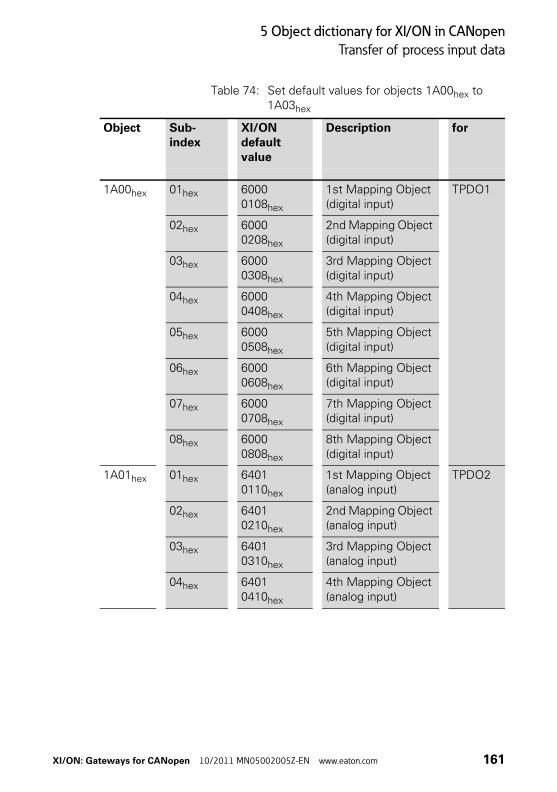
5 Object dictionary for XI/ON in CANopen
Transfer of process input data
Table 74: Set default values for objects 1A00hex to 1A03hex
Object Sub-index
XI/ON default value
Description for
1A00hex 01hex 6000 0108hex
1st Mapping Object (digital input)
TPDO1
02hex 6000 0208hex
2nd Mapping Object (digital input)
03hex 6000 0308hex
3rd Mapping Object (digital input)
04hex 6000 0408hex
4th Mapping Object (digital input)
05hex 6000 0508hex
5th Mapping Object (digital input)
06hex 6000 0608hex
6th Mapping Object (digital input)
07hex 6000 0708hex
7th Mapping Object (digital input)
08hex 6000 0808hex
8th Mapping Object (digital input)
1A01hex 01hex 6401 0110hex
1st Mapping Object (analog input)
TPDO2
02hex 6401 0210hex
2nd Mapping Object (analog input)
03hex 6401 0310hex
3rd Mapping Object (analog input)
04hex 6401 0410hex
4th Mapping Object (analog input)
XI/ON: Gateways for CANopen 10/2011 MN05002005Z-EN www.eaton.com 161

5 Object dictionary for XI/ON in CANopen
Transfer of process input data
The following structure is used for the parameters of the sub-indices 01hex to 40hex:
Table 75: Structure of the PDO mapping entries
1A02hex 01hex 6401 0510hex
1st Mapping Object (analog input)
TPDO3
02hex 6401 0610hex
2nd Mapping Object (analog input)
03 h 6401 0710hex
3rd Mapping Object (analog input)
04hex 6401 0810hex
4th Mapping Object (analog input)
1A03hex 01hex 6401 0910hex
1st Mapping Object (analog input)
TPDO4
02hex 6401 0A10hex
2nd Mapping Object (analog input)
03hex 6401 0B10hex
3rd Mapping Object (analog input)
04hex 6401 0C10hex
4th Mapping Object (analog input)
Object Sub-index
XI/ON default value
Description for
msb lsb
Object-index (16 bit)
Sub-index(8 bit)
Object length(8 bit)
→ To change the number of mapping entries follow the instructions in the section “Procedure for altering PDO mappings” in this chapter.
162 XI/ON: Gateways for CANopen 10/2011 MN05002005Z-EN www.eaton.com

5 Object dictionary for XI/ON in CANopen
Network management
Network management The objects 1F80hex to 1F83hex are only relevant if the XI/ON station is required to perform the func-tions of a network management master. The defi-nition: “The XI/ON station is the NMT master” is executed via bit 0 of object 1F80hex.
Object 1F80hex NMT Startup
The object 1F80hex describes the startup behavior of XI/ON in the NMT (network management).
Table 76: Object 1F80hex Description
Features Sub-index Description / Value
Name NMT StartUp
Object Code VAR
PDO Mapping No
Data Type Sub-index 00hex Unsigned32
Access Sub-index 00hex rw
XI/ON default value Sub-index 00hex No
XI/ON: Gateways for CANopen 10/2011 MN05002005Z-EN www.eaton.com 163

5 Object dictionary for XI/ON in CANopen
Network management
Table 77: Structure of the entry
Bit Value Meaning
0 0 The XI/ON station is not the NMT master. All other bits are ignored. The objects in the network list are ignored.
1 The XI/ON station is the NMT master.
1 0 Only the explicitly selected slaves are started.
1 After the boot-up the service “NMT Start Remote Node All Nodes” is executed.
2 0 XI/ON switches automatically to “Operational” status.
1 XI/ON does not switch automatically to “Operational” status. The status change is defined by the respective appli-cation.
3 0 The start of the slave is permitted.
1 The start of the slave is not permitted.
4 0 An error event of an obligatory slave treats the slave individ-ually.
1 An error event of an obligatory slave initiates an NMT Reset All Nodes (see “Object 1F81hex”, bit 3).
5 to 31 Reserve; set to 0
164 XI/ON: Gateways for CANopen 10/2011 MN05002005Z-EN www.eaton.com

5 Object dictionary for XI/ON in CANopen
Network management
Object 1F81hex Slave Assignment
The object 1F81hex describes as per CiA DSP-302 all slaves that are connected to the NMT master. It contains the information on error control parame-ters and on actions that were triggered by error events. All other parameters for a slave are only valid if this slave is described in object 1F81hex.
Table 78: Object 1F81hex Description
→ The object 1F81hex is only valid if the XI/ON is defined as the NMT master (see object 1F80hex, bit 0).
Features Sub-index Description / Value
Name Slave Assignment
Object Code ARRAY
PDO Mapping No
Data Type Sub-index 00hex Unsigned8
Sub-index 01hex to Sub-index 7Fhex
Unsigned32
Function Sub-index 00hex Supported number of slaves
Sub-index 01hex to Sub-index 7Fhex
Entry for slave with Node-ID 1 to 127 (→ Table 79, Page 166)
Access Sub-index 00hex to Sub-index 7Fhex
rw
XI/ON default value Sub-index 00hex 127
Sub-index 01hex to Sub-index 7Fhex
No
→ Each sub-index corresponds to the slave with the particular Node-ID. The sub-index with the Node-ID of the NMT master is ignored.
XI/ON: Gateways for CANopen 10/2011 MN05002005Z-EN www.eaton.com 165

5 Object dictionary for XI/ON in CANopen
Network management
Table 79: Structure of the entry
Byte Bit Value Meaning
0 0 0 The node with this ID is not a slave.
1 The node with this ID is a slave. After configuration, the node will be put into the “Operational” state.
1 0 An error event or other event detection by a slave during boot-up leads to the notification of the application.
1 An error event or other event detection by a slave during boot-up leads to the notification of the application and to automatic start of Error Control Services.
2 0 An error event or other event detection by a slave during boot-up does not lead to the automatic configuration and starting of the slave.
1 An error event or other event detection by a slave during boot-up leads to the starting of “Start Boot Slaves”.
3 0 Optional slave: the network can also be started if this node is not connected.
1 Obligatory slave: the network will not be started if this node is not connected during the slave boot-up.
4 0 The slave can be reset by the “NMT Reset Communica-tion” command, depending on its state.
1 The NMT master does not have to send an “NMT Reset Communication” command for this slave, if the slave is in the “Operational” state.
5 0 Verification of the application software version is not required for this node.
1 Verification of the application software version is required for this node.
6 0 Automatic update of the application software (download) is not permitted.
1 Automatic update of the application software (download) is permitted.
7 Reserve; set to 0
1 8-Bit value for the Retry Factor
2 to 3 16-bit value for the Guard Time
166 XI/ON: Gateways for CANopen 10/2011 MN05002005Z-EN www.eaton.com

5 Object dictionary for XI/ON in CANopen
Network management
Object 1F82hex Request NMT
The object 1F82hex describes as per CiA DSP-302 all slaves that can send requests to the Network Management (NMT).
Table 80: Object 1F82hex Description
For a write access to this object, the value corre-sponds to the status of the node to which the request is directed. For read access, the object contains the present status of the node.
Features Sub-index Description / Value
Name Request NMT
Object Code ARRAY
PDO Mapping No
Data Type Sub-index 00hex Unsigned8
Sub-index 01hex to Sub-index 80hex
Unsigned8
Function Sub-index 00hex Supported number of slaves
Sub-index 01hex to Sub-index 7Fhex
Request NMT Service for slave with Node-ID 1 to 127 (→ Table 81, Page 168)
Sub-index 80hex Request NMT Service for all slaves
Access Sub-index 00hex ro
Sub-index 00hex to Sub-index 7Fhex
rw
Sub-index 80hex wo
XI/ON default value Sub-index 00hex 127
Sub-index 01hex to Sub-index 80hex
No
XI/ON: Gateways for CANopen 10/2011 MN05002005Z-EN www.eaton.com 167
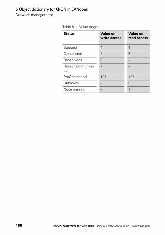
5 Object dictionary for XI/ON in CANopen
Network management
Table 81: Value ranges
Status Value on write access
Value on read access
Stopped 4 4
Operational 5 5
Reset Node 6 –
Reset Communica-tion
7 –
PreOperational 127 127
Unknown – 0
Node missing – 1
168 XI/ON: Gateways for CANopen 10/2011 MN05002005Z-EN www.eaton.com

5 Object dictionary for XI/ON in CANopen
Network management
Object 1F83hex Request Guarding
The object 1F83hex describes as per CiA DSP-302 all slaves that can be monitored by the Network Management (NMT).
Table 82: Object 1F83hex Description
→ The object 1F83hex is only valid if the XI/ON is configured as the NMT master (see object 1F80hex, Bit 0).
Features Sub-index Description / Value
Name Request Guarding
Object Code ARRAY
PDO Mapping No
Data Type Sub-index 00hex Unsigned8
Sub-index 01hex to Sub-index 80hex
Unsigned8
Function Sub-index 00hex Supported number of slaves
Sub-index 01hex to Sub-index 7Fhex
Request Guarding for slaves with the Node-ID 1 to 127 (→ Table 81, Page 168)
Sub-index 80hex Request Start/Stop Guarding for all slaves
Access Sub-index 00hex ro
Sub-index 01hex to Sub-index 7Fhex
rw
Sub-index 80hex wo
XI/ON default value Sub-index 00hex 128
Sub-index 01hex to Sub-index 80hex
No
Value Sub-index 01hex to Sub-index 7Fhex
0 = Slave being monitored at present1 = Slave not being monitored at present
XI/ON: Gateways for CANopen 10/2011 MN05002005Z-EN www.eaton.com 169

5 Object dictionary for XI/ON in CANopen
Manufacturer-specific objects
Manufacturer-specific objects
The following table provides an overview of the manufacturer-specific entries in the Object Dictionary:
Table 83: Overview of the manufacturer-specific Object Dictionary entries
The column Index (hex) describes the position of the entry in the Object Dictionary.The Object column shows a symbolic name for the entry.The Name column shows a simple function description of the entry. The Type column indicates the data type of the entry.
Objects 3000hex to 3097hexObjects 3000hex to 3097hex enable direct access to the internal module bus of the XI/ON station. These objects are generally not used, since access is made through the objects of the Device Profile.
Index (hex) Object Name Type
2000hex VAR Serial No. Unsigned32
2010hex ARRAY Behavior Modifiers Unsigned32
Attention!If these objects are utilized by the user, then the user must ensure that all the relevant conditions are fulfilled for trouble-free, faultless operation of the XI/ON station in the CANopen network.
Eaton Support is always willing to assist you in the use of these objects!
170 XI/ON: Gateways for CANopen 10/2011 MN05002005Z-EN www.eaton.com

5 Object dictionary for XI/ON in CANopen
Manufacturer-specific objects
Object 2000hex Serial Number
The object 2000hex corresponds to the Sub-index 04hex of object 1018hex and contains the serial number of the XI/ON gateway that is used.
Object 2010hex Behaviour Modifiers
The object 2010hex is used for a temporary (vola-tile) modification to the module behavior.
Table 84: Object 2010hex Description
→ We recommend using object 1018hex, sub-index 04hex for the serial number.
Features Sub-index Description / Value
Name Behaviour Modifiers
Object Code ARRAY
PDO Mapping No
Data Type Sub-index 00hex Unsigned8
Sub-index 01hex to Sub-index 03hex
Unsigned32
Function Sub-index 00hex No. of entries
Sub-index 01hex Hard Reset Modifier
Sub-index 02hex Save Ref Reset Modifier
Sub-index 03hex Save Current Reset Modifier
Access Sub-index 00hex ro
Sub-index 01hex to Sub-index 03hex
rw
XI/ON default value Sub-index 01hex to Sub-index 03hex
No
XI/ON: Gateways for CANopen 10/2011 MN05002005Z-EN www.eaton.com 171

5 Object dictionary for XI/ON in CANopen
Manufacturer-specific objects
Sub-index 01hex:
The Hard Reset Modifier determines in the event of a Reset Node command, whether a normal, fast or a hard processor reset is carried out which requires several seconds.
For the write operation, the transferred value is interpreted as a string in the Unsigned32 format:
Table 85: Preselect Hard Reset (Processor Reset)
Table 86: Preselect normal reset
After the next Reset Node or the next “Reset Communication” command, the operating mode will in all cases be reset to “normal Reset Node”.
Sub-index 02hex:
The Index “Save Ref Reset Modifier”determines that, in the event of a Reset Node command, the XI/ON Reference Module List (Objects 3080hex and 3081hex) will be saved in non-volatile memory and then followed by a hard processor reset. This hardware reset is necessary, because changes to the XI/ON Reference Module List cannot be dynamically accepted in the CANopen I/O image. If the module list is altered, all the CANopen parameters will be reset to the default values.
For writing, the value that is transferred in Unsigned32 format will be interpreted as a string:
msb lsb
t s r h
74hex 73hex 72hex 68hex
msb lsb
t s r s
74hex 73hex 72hex 73hex
172 XI/ON: Gateways for CANopen 10/2011 MN05002005Z-EN www.eaton.com

5 Object dictionary for XI/ON in CANopen
Manufacturer-specific objects
Table 87: Save and Hardware Reset selection
Table 88: Preselect normal reset
After the next Reset Node or the next “Reset Communication” command, the operating mode will in all cases be reset to “normal Reset Node”.
Sub-index 03hex:
The Index “Save Current Reset Modifier”deter-mines that, in the event of a Reset Node command, the current XI/ON Reference Module List (Objects 3090hex and 3091hex) will be saved in non-volatile memory, and then followed by a hard processor reset. This hardware reset is necessary, because changes to the XI/ON Reference Module List cannot be dynamically accepted in the CANopen I/O image. If the module list is altered, all the CANopen parameters will be reset to the default values.
For the write operation, the transferred value is interpreted as a string in the Unsigned32 format:
msb lsb
v a s r
76hex 61hex 73hex 72hex
msb lsb
t s r s
74hex 73hex 72hex 73hex
XI/ON: Gateways for CANopen 10/2011 MN05002005Z-EN www.eaton.com 173
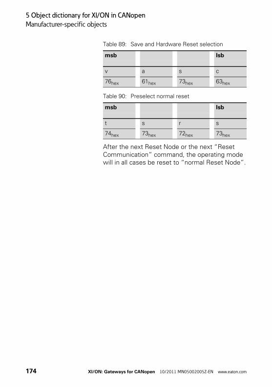
5 Object dictionary for XI/ON in CANopen
Manufacturer-specific objects
Table 89: Save and Hardware Reset selection
Table 90: Preselect normal reset
After the next Reset Node or the next “Reset Communication” command, the operating mode will in all cases be reset to “normal Reset Node”.
msb lsb
v a s c
76hex 61hex 73hex 63hex
msb lsb
t s r s
74hex 73hex 72hex 73hex
174 XI/ON: Gateways for CANopen 10/2011 MN05002005Z-EN www.eaton.com
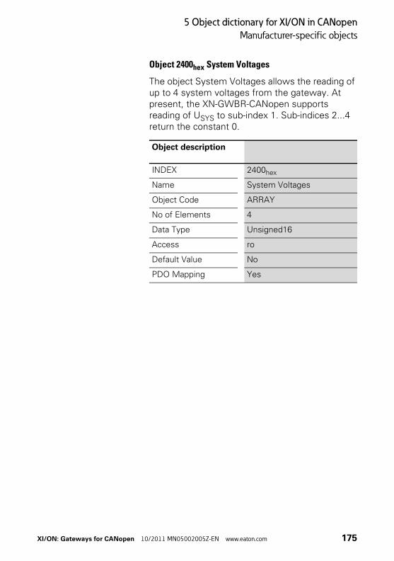
5 Object dictionary for XI/ON in CANopen
Manufacturer-specific objects
Object 2400hex System Voltages
The object System Voltages allows the reading of up to 4 system voltages from the gateway. At present, the XN-GWBR-CANopen supports reading of USYS to sub-index 1. Sub-indices 2...4 return the constant 0.
Object description
INDEX 2400hex
Name System Voltages
Object Code ARRAY
No of Elements 4
Data Type Unsigned16
Access ro
Default Value No
PDO Mapping Yes
XI/ON: Gateways for CANopen 10/2011 MN05002005Z-EN www.eaton.com 175

5 Object dictionary for XI/ON in CANopen
Diagnostic messages
Diagnostic messages The XI/ON-CANopen gateway and various XI/ON modules can generate diagnostics messages that can trigger an Emergency Frame.
The gateway transmits the following diagnostics:
• Checking the status of the XI/ON station
• Checking the communication via the internal module bus
• Checking the communication to PROFIBUS-DP
• Checking the status of the gateway
Diagnostics messages are indicated in two different ways:
• via the individual LEDs:
– XN standard gateways:→ Chapter “Diagnostics LED indications“, Page 40
– XNE ECO gateways:→ Chapter “Diagnostic messages via LEDs“, Page 61
• via a CANopen configuration tool (software):→ Chapter “Diagnostics messages via software“, Page 176
Diagnostics messages via software
The diagnostics messages of the XI/ON-CANopen gateway and the XI/ON modules can be displayed using a CANopen configuration tool.
An example of diagnostics messages using a CANopen configuration tool can be found in Chapter 3, Section “Example of a ProCANopen diagnostics message”.
176 XI/ON: Gateways for CANopen 10/2011 MN05002005Z-EN www.eaton.com

5 Object dictionary for XI/ON in CANopen
Diagnostic messages
Description of the gateway diagnostics
Table 91: Diagnostics for XI/ON-CANopen gateway
Diagnostics Error Code
Designation as per CiA DS-301 / DS-401
Meaning
Error Reset / No Error 0000hex - Error Reset
Mains voltage too high1)
3110hex Mains voltage too high
System voltage too high
Mains voltage too low1)
3120hex Mains voltage too low System voltage too low
Field voltage too low1) 3320hex Output voltage too low
Field voltage too low
Deviating I/O configu-ration
707Ahex Additional modules I/O module list, adaptable change, e.g. module removed
I/O configuration error 707Dhex Additional modules I/O module list, incompatible change
Deviating I/O configu-ration - module expan-sion
707Ehex Additional modules I/O module list, expanded
Deviating I/O configu-ration - module removed
707Fh Additional modules 1 module removed from I/O module list
CAN Warning level reached
8100hex Communication CAN communication faulty (at least one of the error counters for the CAN controller of the XI/ON-CANopen gateway has reached the value 96)
CAN Transmit Timeout 8100hex Communication The XI/ON-CANopen gateway was not able to transmit a frame within the specified time.
XI/ON: Gateways for CANopen 10/2011 MN05002005Z-EN www.eaton.com 177

5 Object dictionary for XI/ON in CANopen
Diagnostic messages
1) Only at XN-GWBR-CANopen and XNE-GWBR-CANopen
Life Guard Error or Heartbeat Error
8130hex Life guard error or heartbeat error
The XI/ON-CANopen gateway has detected an error in the CANopen Guarding or Heart-beat Protocol, e.g. a timeout.
Left CAN-BusOff 8140hex Recovered from Bus-Off
The system has left the CAN-Bus Off state, i.e. the CAN controller for the XI/ON-CANopen gateway has moved out of this serious fault condition.
I/Oassistant Force Mode active
9009hex External Error Force Mode acti-vated (I/Oassistant), i.e. the outputs of the XI/ON station are currently not under the control of CANopen
Diagnostics Error Code
Designation as per CiA DS-301 / DS-401
Meaning
178 XI/ON: Gateways for CANopen 10/2011 MN05002005Z-EN www.eaton.com
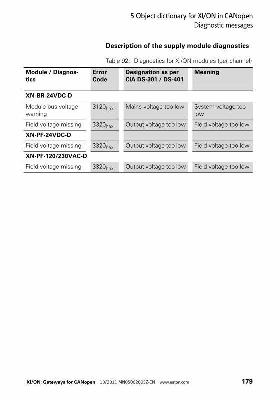
5 Object dictionary for XI/ON in CANopen
Diagnostic messages
Description of the supply module diagnostics
Table 92: Diagnostics for XI/ON modules (per channel)
Module / Diagnos-tics
Error Code
Designation as per CiA DS-301 / DS-401
Meaning
XN-BR-24VDC-D
Module bus voltage warning
3120hex Mains voltage too low System voltage too low
Field voltage missing 3320hex Output voltage too low Field voltage too low
XN-PF-24VDC-D
Field voltage missing 3320hex Output voltage too low Field voltage too low
XN-PF-120/230VAC-D
Field voltage missing 3320hex Output voltage too low Field voltage too low
XI/ON: Gateways for CANopen 10/2011 MN05002005Z-EN www.eaton.com 179

5 Object dictionary for XI/ON in CANopen
Maximum topology
Maximum topology A bus line must have at least two nodes (stations). These could be, for example, a PLC or a PC with a CANopen compliant plug-in card, and a XI/ON gateway. The connection of a XI/ON station to the CANopen network can only be made through the XI/ON gateway.
Incoming and outgoing cables are connected through SUBD plug/socket connectors or through direct wiring. Each XI/ON gateway behaves as an active node, and thus has a Node-ID assigned.
Maximum system configurationof a CANopen bus line
A CANopen bus line can have a maximum of 110 nodes. This maximum number must not be exceeded.
The way to set the Node-ID depends on the gateway type:
• On the stadard gateways, the Node-ID is set through the two rotary encoding switches (→ Chapter “Node-ID setting“, Page 35). Adjustable addresses (Node-IDs):
– XN-GW-CANopen: 1 to 127
– XN-GWBR-CANopen: 1 to 99
• On the XNE ECO gateways, the Node-ID is set through DIP switches (→ Chapter “Setting the Node-ID“, Page 56). Adjustable addresses (Node-IDs):
– XNE-GWBR-CANopen: 1 to 63
It is not possible to assign Node-IDs directly via the bus.
180 XI/ON: Gateways for CANopen 10/2011 MN05002005Z-EN www.eaton.com

5 Object dictionary for XI/ON in CANopen
Maximum topology
→ Within a XI/ON station with the XNE ECO gateway XNE-GWBR-CANopen, the maximum number of modules is limited. Please note Chapter “Maximum station extension“, Page 64.
XI/ON: Gateways for CANopen 10/2011 MN05002005Z-EN www.eaton.com 181
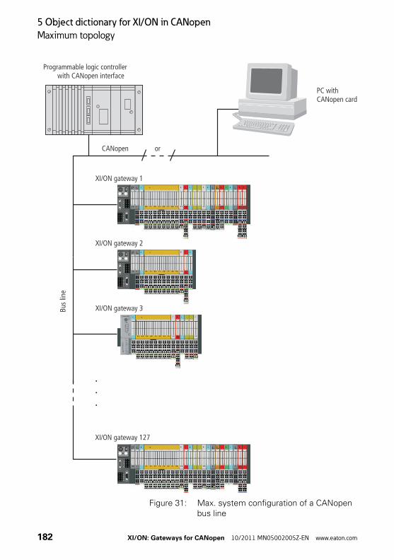
5 Object dictionary for XI/ON in CANopen
Maximum topology
Figure 31: Max. system configuration of a CANopen bus line
.
.
.
CANopen or
Programmable logic controllerwith CANopen interface
PC withCANopen card
XI/ON gateway 127
XI/ON gateway 1
Bus
line
XI/ON gateway 2
XI/ON gateway 3
182 XI/ON: Gateways for CANopen 10/2011 MN05002005Z-EN www.eaton.com

5 Object dictionary for XI/ON in CANopen
Maximum topology
Maximum bus length
The maximum bus length for CANopen depends on the transmission rate that is used. The following table shows an overview of the possible transmission rates and the corresponding maximum cable lengths:
Table 93: Maximum cable lengths
For bus lengths of 1000 m or more, it may be necessary to insert repeaters.
Bit transfer rate (Kbit/s)
Maximum cable length (m)
10 1000
20 1000
50 1000
100 650
125 500
250 250
500 100
800 50
1000 25
XI/ON: Gateways for CANopen 10/2011 MN05002005Z-EN www.eaton.com 183

5 Object dictionary for XI/ON in CANopen
Mixed operation with other types of station
Mixed operation with other types of station
In addition to the XI/ON gateways, other stations (e.g. other station types and modules from the WIN bloc series, or third-party devices that comply with the CANopen profile family) can also be inte-grated into the field bus system, so that mixed operation is possible. The CANopen system is thus extremely flexible, and can be applied even in the most difficult industrial environments.
184 XI/ON: Gateways for CANopen 10/2011 MN05002005Z-EN www.eaton.com
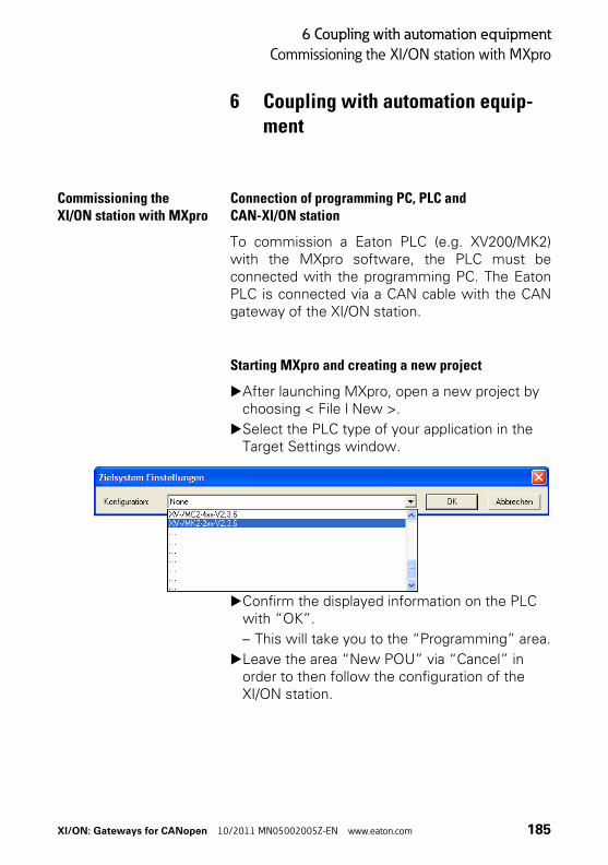
6 Coupling with automation equipment
Commissioning the XI/ON station with MXpro
6 Coupling with automation equip-ment
Commissioning the XI/ON station with MXpro
Connection of programming PC, PLC and CAN-XI/ON station
To commission a Eaton PLC (e.g. XV200/MK2)with the MXpro software, the PLC must beconnected with the programming PC. The EatonPLC is connected via a CAN cable with the CANgateway of the XI/ON station.
Starting MXpro and creating a new project
▶After launching MXpro, open a new project by choosing < File l New >.
▶Select the PLC type of your application in the Target Settings window.
▶Confirm the displayed information on the PLC with “OK”.
– This will take you to the “Programming” area.
▶Leave the area “New POU” via “Cancel” in order to then follow the configuration of the XI/ON station.
XI/ON: Gateways for CANopen 10/2011 MN05002005Z-EN www.eaton.com 185

6 Coupling with automation equipment
Commissioning the XI/ON station with MXpro
Integrating the CAN master
Complete the following steps to enable communi-cation via CANopen:▶To configure the XI/ON station click the
Resources tab.
Figure 32: Selecting Configuration mode
▶Choose the PLC Configuration element from the configuration tree.
186 XI/ON: Gateways for CANopen 10/2011 MN05002005Z-EN www.eaton.com
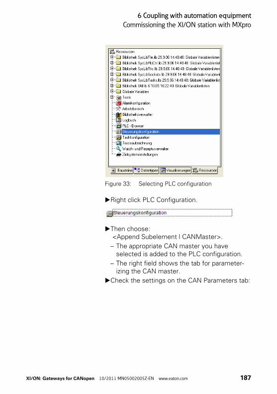
6 Coupling with automation equipment
Commissioning the XI/ON station with MXpro
Figure 33: Selecting PLC configuration
▶Right click PLC Configuration.
▶Then choose: <Append Subelement l CANMaster>.
– The appropriate CAN master you have selected is added to the PLC configuration.
– The right field shows the tab for parameter-izing the CAN master.
▶Check the settings on the CAN Parameters tab:
XI/ON: Gateways for CANopen 10/2011 MN05002005Z-EN www.eaton.com 187

6 Coupling with automation equipment
Commissioning the XI/ON station with MXpro
Figure 34: CAN parameters of the CAN master
– The baud rate setting of the master must be the same as that of the slave (in this case: XN-GWBR-CANopen).
– The maximum bus length determines which is the most suitable transfer rate (→ Chapter “Maximum bus length“, Page 183).
– The setting for the transfer rate of the XN-GWBR-CANopen is made using DIP switches (→ Chapter “Setting the bit transfer rate via DIP switches“, Page 33).
– The next three entry fields are used to activate a Synchronisation message.
– The “Node ID” of the master must be between 1 and 127 must only be assigned once in the entire network.
– The selected “Automatic startup” option ensures that the CAN bus is initialized and started automatically. Without this function activated, the CAN bus must be started in the project.
– The Support DSP301,V4.01 and DSP306 option enables the clock rate for the Heart-beat function to be set.
188 XI/ON: Gateways for CANopen 10/2011 MN05002005Z-EN www.eaton.com

6 Coupling with automation equipment
Commissioning the XI/ON station with MXpro
→ Refer to the MXpro documentation for further information.
XI/ON: Gateways for CANopen 10/2011 MN05002005Z-EN www.eaton.com 189

6 Coupling with automation equipment
Commissioning the XI/ON station with MXpro
Integrating the CAN slave
▶In order to add the CAN slave (in this case: XN-GWBR-CANopen) to your configuration, right-click the “CanMaster[xxx]” element:
▶Then select:<Append Subelement>.
– The list shows all configurable slaves:
Figure 35: Add CAN slave
▶Select the appropriate CAN slave.
– The selected CAN slave is added to the PLC configuration.
▶Update your MXpro version if your product is not shown.
– Updates can be obtained from our website(www.eaton-automation.com),under “DOWNLOADS”.
190 XI/ON: Gateways for CANopen 10/2011 MN05002005Z-EN www.eaton.com

6 Coupling with automation equipment
Commissioning the XI/ON station with MXpro
Configuration of the XI/ON gatewayThe right field shows the tab for parameterizing the CAN slave.
▶Check the settings on the CAN Parameters tab:
– The “Node ID” of the slave:
– is set with the rotary encoding switches on the housing,
– must be set between 1 and 127. – and must only be assigned once in the entire
network.
Figure 36: CAN parameters of the CAN slave (in this case: XN-GWBR-CANopen)
→ Compare the Node ID set with the rotary encoding switches and the Node ID on the tab!
Adjust the Node-ID if necessary!
XI/ON: Gateways for CANopen 10/2011 MN05002005Z-EN www.eaton.com 191

6 Coupling with automation equipment
Commissioning the XI/ON station with MXpro
→ Refer to the MXpro documentation for further information.
192 XI/ON: Gateways for CANopen 10/2011 MN05002005Z-EN www.eaton.com

6 Coupling with automation equipment
Commissioning the XI/ON station with MXpro
Configuration of the XI/ON modules▶To configure the XI/ON station click the CAN
Module Selection tab.
Figure 37: CAN module selection of the CAN slave (in this case: XN-GWBR-CANopen)
– This tab has two windows:
– The left-hand window contains a list of avail-able module types.
– The right-hand window contains a list of the module types of your station.
▶To configure a XI/ON module, select the module type in the left-hand window and then click:<Add>.
→ You can add other XI/ON modules at any posi-tion:▶In the left-hand window select the module
type and in the right-hand window the required position.
▶Click <Add>.
– The selected XI/ON module is positioned directly in front of the selected module.
XI/ON: Gateways for CANopen 10/2011 MN05002005Z-EN www.eaton.com 193

6 Coupling with automation equipment
Commissioning the XI/ON station with MXpro
Inactive process data objectsSome process data objects are not activated auto-matically. These objects can only take part in process data exchange if they are enabled manu-ally (→ Chapter “Activation of the default PDOs / manual “enabling” of process data“, Page 196).
The inactive process data objects are reported every time the configuration is changed.
Figure 38: Indication of inactive PDOs
You can activate these inactive objects immedi-ately after the first message or after the entire configuration has been completed.
Mapping immediately after the first message simplifies the assignment of the inactive object to the module type.
The process data objects are updated automati-cally if the equipment of the XI/ON station meets the following criteria:
• Maximum of 64 digital input channels
• Maximum of 64 digital output channels
• Maximum of 12 analog input channels
• Maximum of 12 analog output channels
• No technology module
This default “mapping” and activation of the process data conforms with the CiA DS-301 Communication Profile.
→ Chapter “Default PDOs and PDO mappings“, Page 101.
194 XI/ON: Gateways for CANopen 10/2011 MN05002005Z-EN www.eaton.com
6 Coupling with automation equipment
Commissioning the XI/ON station with MXpro
→ If the XI/ON station is fitted with more input and output channels than listed above or contains technology modules, the process data objects must be enabled manually (→ Chapter “Activation of the default PDOs / manual “enabling” of process data“, Page 196).
XI/ON: Gateways for CANopen 10/2011 MN05002005Z-EN www.eaton.com 195
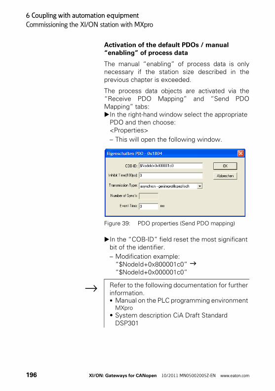
6 Coupling with automation equipment
Commissioning the XI/ON station with MXpro
Activation of the default PDOs / manual “enabling” of process data
The manual “enabling” of process data is onlynecessary if the station size described in theprevious chapter is exceeded.
The process data objects are activated via the“Receive PDO Mapping” and “Send PDOMapping” tabs:▶In the right-hand window select the appropriate
PDO and then choose:<Properties>
– This will open the following window.
Figure 39: PDO properties (Send PDO mapping)
▶In the “COB-ID” field reset the most significant bit of the identifier.
– Modification example: “$NodeId+0x800001c0” “$NodeId+0x000001c0”
→ Refer to the following documentation for further information.• Manual on the PLC programming environment
MXpro
• System description CiA Draft Standard DSP301
196 XI/ON: Gateways for CANopen 10/2011 MN05002005Z-EN www.eaton.com

6 Coupling with automation equipment
Commissioning the XI/ON station with MXpro
Integrating the librariesfor CANopen communication
After the CAN master is added and the program iscompiled for the first time, all the libraries requiredfor CANopen communication are added automati-cally.
If this does not occur, add the required librariesmanually using the Library Manager:▶On the Resources tab select the Library
Manager element on the configuration tree.
Figure 40: Selecting the Library Manager
→ Refer to the relevant PLC documentation for further information.
XI/ON: Gateways for CANopen 10/2011 MN05002005Z-EN www.eaton.com 197

6 Coupling with automation equipment
Commissioning the XI/ON station with MXpro
198 XI/ON: Gateways for CANopen 10/2011 MN05002005Z-EN www.eaton.com

Index
Index
A address setting ......................................................... 56Approvals ............................................................ 16, 50
B baud rate ................................................................... 58Bus ............................................................................ 43Bus lengths
Maximum......................................................... 183bus terminating resistor............................................ 59
C CANopenNetwork Management messages..................... 69Process Data Objects (PDOs)............................. 69Service Data Objects (SDOs)............................. 69
COB-ID....................................................................... 77communication bytes ................................................ 64Configuration button ................................................. 38
D Degree of protection ........................................... 16, 50Diagnostics ............................................................. 177DIP switches ............................................................. 56Direct wiring
CANopen ......................................................... 180
E Electromagnetic compatibility .................................. 14Electronic data sheet ................................................ 72Emergency Frame...................................................... 83Err .............................................................................. 42
F Fieldbus connectionDirect wiring...................................................... 24Open style connector......................................... 28SUB-D socket..................................................... 22
XI/ON: Gateways for CANopen 10/2011 MN05002005Z-EN www.eaton.com 199
Index
G GW ............................................................................ 40
I Indication elements ................................................ 176IOs ............................................................................. 41
L LEDBus..................................................................... 43Err ...................................................................... 42GW..................................................................... 40IOs...................................................................... 41
M Maximum bus length .............................................. 183Mixed operation...................................................... 184
N Node-ID ............................................................... 35, 77NODE-ID setting........................................................ 56
O Operating life ...................................................... 16, 50
P PDO Mapping .......................................................... 109Pin assignment.......................................................... 28Process Data Object (PDO)........................................ 96Process Data Objects (PDOs) .................................... 69
R Repeater.................................................................. 183Rotary encoding switch
Decimal.............................................................. 37Hexadecimal...................................................... 36
Rotary hex encoding switch...................................... 36
S Service Data Object (SDO) ........................................ 91Service interface ................................................. 31, 54SUB-D plug.............................................................. 180SUB-D socket .......................................................... 180Supply voltage .................................................... 13, 18supply voltage ........................................................... 52
200 XI/ON: Gateways for CANopen 10/2011 MN05002005Z-EN www.eaton.com

Index
T tension clamp terminals ........................................... 53Terminating resistor.................................................. 22Topology.................................................................. 180Transfer rate ........................................................... 183Transmission Type .................................................... 97
XI/ON: Gateways for CANopen 10/2011 MN05002005Z-EN www.eaton.com 201

Index
202 XI/ON: Gateways for CANopen 10/2011 MN05002005Z-EN www.eaton.com