gates hose coupling selection
TRANSCRIPT
Seven Easy Steps For Selecting The Proper HoseAn effective way to remember hose selection criteria is to remember the word...
S T A M P E D
S = Size
T = Temperature
A = Application
M = Material to be conveyed
P = Pressure
E = Ends or couplings
D = Delivery (volume and velocity)
1. Hose Size (Dash Numbers)
The inside diameter of the hose must be ade-quate to keep pressure loss to a minimum andavoid damage to the hose due to heat genera-tion or excessive turbulence. See hose sizingNomographic Chart on page C63.
To determine the replacement hose size, readthe layline printing on the side of the originalhose. If the original hose layline is painted overor worn off, the original hose must be cut andthe inside diameter measured for size.
NOTE: Before cutting an original hose assem-bly, measure the overall assembly length andfitting orientation. These measurements will berequired to build the replacement assembly.
The hydraulics industry has adopted a measur-ing system called Dash Numbers to indicatehose and coupling size. The number whichprecedes the hose or coupling description isthe dash size (see following table). This industrystandard number denotes hose I.D. in six-teenths of an inch. (The exception to this is theSAE100R5 hoses C5C, C5D, C5E, C5M as wellas, C14 and AC134a, where dash sizes denotehose I.D. equal to equivalent tube O.D.) Seechart to the right.
Hose I.D. (Inches)
All Except C5 Series, C5 Series, C14 andC14 and AC134a AC134a
Dash No. Inches Millimeters Inches Millimeters
-2 1/8 3.2 -- --
-3 3/16 4.8 -- --
-4 1/4 6.4 3/16 4.8
-5 5/16 7.9 1/4 6.4
-6 3/8 9.5 5/16 7.9
-8 1/2 12.7 13/32 10.3
-10 5/8 15.9 1/2 12.7
-12 3/4 19.0 5/8 15.9
-14 7/8 22.2 -- --
-16 1 25.4 7/8 22.2
-20 1-1/4 31.8 1-1/8 28.6
-24 1-1/2 38.1 1-3/8 34.9
-32 2 50.8 1-13/16 46.0
-36 2-1/4 57.6 -- --
-40 2-1/2 63.5 2-3/8 60.3
-48 3 76.2 -- --
-56 3-1/2 88.9 -- --
-64 4 101.6 -- --
-72 4-1/2 115.2 -- --
EQUIPMENT
HOSE/CPLG.SELECTION
TECH. DATA
EXT. & VERY HIGHPRESS. HOSE
GS CPLGS.
PCM CPLGS.
PCS CPLGS.
HIGH & MED.PRESS. HOSE
MEGACRIMP®
CPLGS.
PC CPLGS.
FIELD ATTACHABLECPLGS.
AIR BRAKEHOSE &CPLGS.
MEGATECH®/C5HOSE &CPLGS.
LOW PRESS.HOSE & CPLGS.
C14 HOSE& CPLGS.
POLARSEAL®
HOSE & CPLGS.
PWR. STG.HOSE & CPLGS.
THERMO-PLASTICHOSE & CPLGS.
ADAPTERS
QUICK DISCONNECTCPLGS.
ACCESSORIES& ASSORT-MENTS
PART NUMBERINDEXES
FL
EE
T
Hose & Coupling Selection
Gates CorporationC1 www.gates.com ®
The World’s Most Trusted Name in Belts, Hose and Hydraulics.® www.gates.com C2
EQUIPMENT
HOSE/CPLG.SELECTION
TECH. DATA
EXT. & VERY HIGHPRESS. HOSE
GS CPLGS.
PCM CPLGS.
PCS CPLGS.
HIGH & MED.PRESS. HOSE
MEGACRIMP®
CPLGS.
PC CPLGS.
FIELD ATTACHABLECPLGS.
AIR BRAKEHOSE & CPLGS.
MEGATECH®/C5HOSE & CPLGS.
LOW PRESS.HOSE & CPLGS.
C14 HOSE& CPLGS.
POLARSEAL®
HOSE & CPLGS.
PWR. STG.HOSE & CPLGS.
THERMO-PLASTICHOSE & CPLGS.
ADAPTERS
QUICK DISCONNECTCPLGS.
ACCESSORIES& ASSORT-MENTS
PART NUMBERINDEXES
FL
EE
T
Hose & Coupling Selection
Selecting The Proper Hose — con’t.Hose O.D. can be a critical factor when hose routingclamps are used or hoses are routed through bulkheads.Check individual hose specification tables for O.D.’s.
2. Temperature
When selecting a replacement assembly, two areas oftemperature must be considered. These are fluid tem-perature and ambient temperature. The hose selectedmust be capable of withstanding the minimum andmaximum temperature seen by the system. Caremust be taken when routing near hot manifolds andin extreme cases a heat shield may be advisable.
See the Gates Hydraulic Hose Selection Guide onpages C4 and C5; Hose Specification Pages; and/orthe Additional Temperature Limits For Gates HydraulicHoses Chart on page C8 for temperature ranges andlimits for water, water/oil emulsions and water/glycolsolutions.
3. Application
Determine where or how the replacement hose orassembly is to be used. Most often only a duplicateof the original hose will have to be made. To fulfill therequirements of the application, additional questionsmay need to be answered, such as:
■ Where will hose be used? ■ Fluid and/or Ambient Temperature? ■ Hose Construction?■ Equipment Type? ■ Fluid Compatibility? ■ Thread End Connection Type?■ Working and Surge Pressures? ■ Environmental Conditions? ■ Permanent or Field Attachable Couplings?■ Suction Application? ■ Routing Requirements? ■ Thread Type?■ Government and Industry Standards Being Met? ■ Unusual Mechanical Loads? ■ Minimum Bend Radius? ■ Non-Conductive Hose Required? ■ Excessive Abrasion?
4. Material to be Conveyed
Some applications require specialized oils or chemicalsto be conveyed through the system. Hose selectionmust assure compatibility of the hose tube, cover,couplings and O-rings with the fluid used. Additionalcaution must be exercised in hose selection forgaseous applications such as refrigerants and LPG.
NOTE: All block type couplings contain nitrile O-ringswhich must be compatible with the fluids being used.
5. Pressure
Most important in the hose selection process isknowing system pressure, including pressure spikes.Published working pressures must be equal to orgreater than the system pressure. Pressure spikesgreater than the published working pressure willshorten hose life and must be taken into consideration.Gates DOES NOT recommend using hoses onapplications having pressure spikes greater thanpublished working pressures of the hose.
6. Ends of Couplings
Identify end connections using Gates couplingtemplates and measuring tools on pages C25 orCoupling Identification section pages C27-C40.Once thread ends have been identified, consult theappropriate section of the catalog for specific partnumber selection.
7. Delivery (Volume and Velocity)
If the same I.D. of the original hose is used, assumethe system is properly sized to efficiently transportfluid. If the system is new or altered, determine thehose I.D. needed to transport required fluid volumeflow by using the Nomographic Chart on page C63.
Gates CorporationC3 www.gates.com ®
EQUIPMENT
HOSE/CPLG.SELECTION
TECH. DATA
EXT. & VERY HIGHPRESS. HOSE
GS CPLGS.
PCM CPLGS.
PCS CPLGS.
HIGH & MED.PRESS. HOSE
MEGACRIMP®
CPLGS.
PC CPLGS.
FIELD ATTACHABLECPLGS.
AIR BRAKEHOSE &CPLGS.
MEGATECH®/C5HOSE &CPLGS.
LOW PRESS.HOSE & CPLGS.
C14 HOSE& CPLGS.
POLARSEAL®
HOSE & CPLGS.
PWR. STG.HOSE & CPLGS.
THERMO-PLASTICHOSE & CPLGS.
ADAPTERS
QUICK DISCONNECTCPLGS.
ACCESSORIES& ASSORT-MENTS
PART NUMBERINDEXES
FL
EE
T
Hose & Coupling Selection
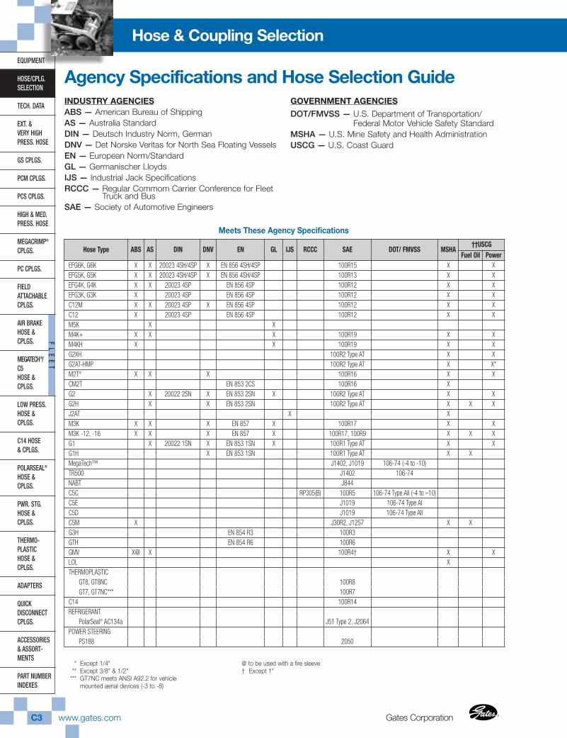
INDUSTRY AGENCIESABS — American Bureau of ShippingAS — Australia StandardDIN — Deutsch Industry Norm, GermanDNV — Det Norske Veritas for North Sea Floating VesselsEN — European Norm/StandardGL — Germanischer LloydsIJS — Industrial Jack SpecificationsRCCC — Regular Commom Carrier Conference for Fleet
Truck and BusSAE — Society of Automotive Engineers
GOVERNMENT AGENCIES
DOT/FMVSS — U.S. Department of Transportation/Federal Motor Vehicle Safety Standard
MSHA — U.S. Mine Safety and Health AdministrationUSCG — U.S. Coast Guard
Agency Specifications and Hose Selection Guide
Meets These Agency Specifications
* Except 1/4"** Except 3/8" & 1/2"
*** GT7NC meets ANSI A92.2 for vehiclemounted aerial devices (-3 to -8)
@ to be used with a fire sleeve† Except 1"
Hose Type ABS AS DIN DNV EN GL IJS RCCC SAE DOT/ FMVSS MSHA††USCG
Fuel Oil PowerEFG6K, G6K X X 20023 4SH/4SP X EN 856 4SH/4SP 100R15 X XEFG5K, G5K X X 20023 4SH/4SP X EN 856 4SH/4SP 100R13 X XEFG4K, G4K X X 20023 4SP EN 856 4SP 100R12 X XEFG3K, G3K X 20023 4SP EN 856 4SP 100R12 X XC12M X X 20023 4SP X EN 856 4SP 100R12 X XC12 X 20023 4SP EN 856 4SP 100R12 X XM5K X XM4K+ X X X 100R19 X XM4KH X X 100R19 X XG2XH 100R2 Type AT X XG2AT-HMP 100R2 Type AT X X*M2T® X X X 100R16 X XCM2T EN 853 2CS 100R16 XG2 X 20022 2SN X EN 853 2SN X 100R2 Type AT X XG2H X X EN 853 2SN 100R2 Type AT X X XJ2AT X XM3K X X X EN 857 X 100R17 X XM3K -12, -16 X X X EN 857 X 100R17, 100R9 X X XG1 X 20022 1SN X EN 853 1SN X 100R1 Type AT X XG1H X EN 853 1SN 100R1 Type AT X XMegaTech™ J1402, J1019 106-74 (-4 to -10)TR500 J1402 106-74NABT J844C5C RP305(B) 100R5 106-74 Type AII (-4 to –10)C5E J1019 106-74 Type AIC5D J1019 106-74 Type AIIC5M X J30R2, J1257 X XG3H EN 854 R3 100R3GTH EN 854 R6 100R6GMV X@ X 100R4† X XLOL XTHERMOPLASTIC
GT8, GT8NC 100R8GT7, GT7NC*** 100R7
C14 100R14REFRIGERANT
PolarSeal® AC134a J51 Type 2, J2064POWER STEERING
PS188 2050
The World’s Most Trusted Name in Belts, Hose and Hydraulics.® www.gates.com C4
EQUIPMENT
HOSE/CPLG.SELECTION
TECH. DATA
EXT. & VERY HIGHPRESS. HOSE
GS CPLGS.
PCM CPLGS.
PCS CPLGS.
HIGH & MED.PRESS. HOSE
MEGACRIMP®
CPLGS.
PC CPLGS.
FIELD ATTACHABLECPLGS.
AIR BRAKEHOSE & CPLGS.
MEGATECH®/C5HOSE & CPLGS.
LOW PRESS.HOSE & CPLGS.
C14 HOSE& CPLGS.
POLARSEAL®
HOSE & CPLGS.
PWR. STG.HOSE & CPLGS.
THERMO-PLASTICHOSE & CPLGS.
ADAPTERS
QUICK DISCONNECTCPLGS.
ACCESSORIES& ASSORT-MENTS
PART NUMBERINDEXES
FL
EE
T
Hose & Coupling Selection
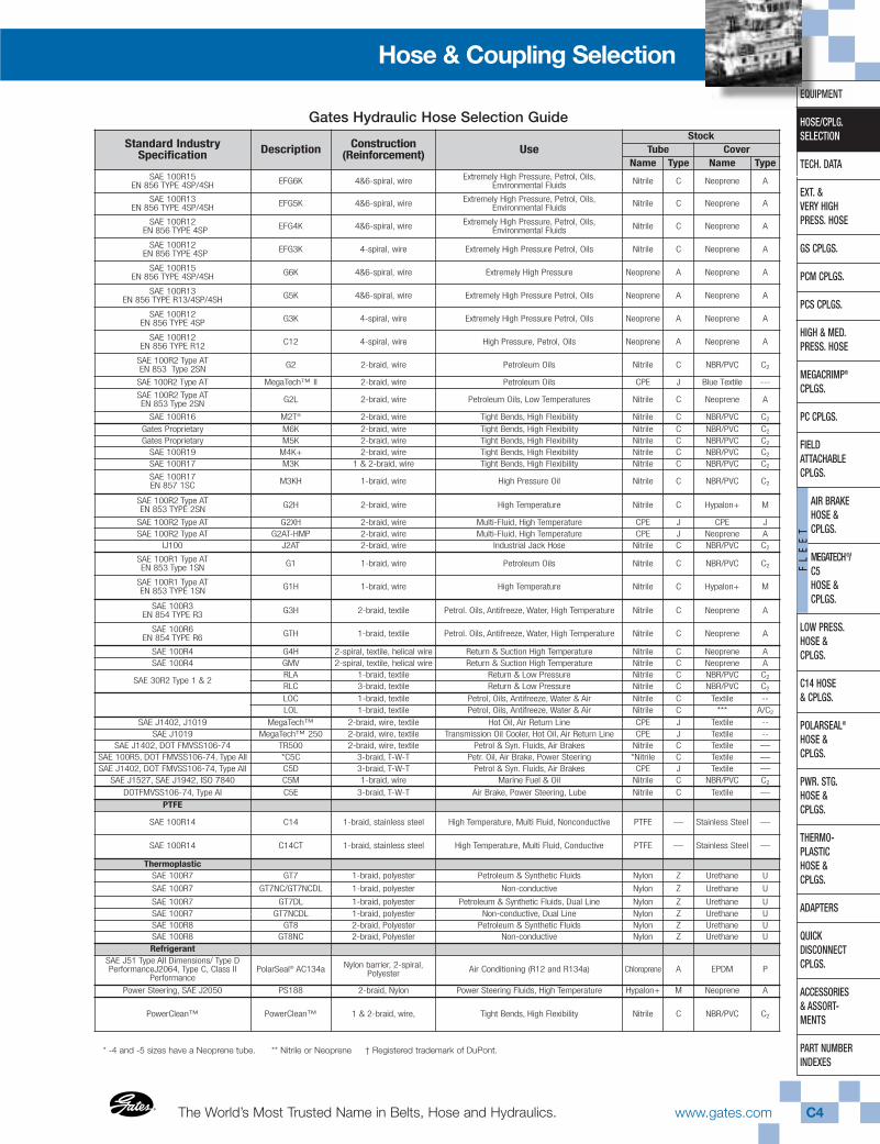
Gates Hydraulic Hose Selection Guide
Standard IndustrySpecification Description Construction
(Reinforcement) UseStock
Tube Cover Name Type Name Type
SAE 100R15EN 856 TYPE 4SP/4SH EFG6K 4&6-spiral, wire Extremely High Pressure, Petrol, Oils,
Environmental Fluids Nitrile C Neoprene A
SAE 100R13EN 856 TYPE 4SP/4SH EFG5K 4&6-spiral, wire Extremely High Pressure, Petrol, Oils,
Environmental Fluids Nitrile C Neoprene A
SAE 100R12EN 856 TYPE 4SP EFG4K 4&6-spiral, wire Extremely High Pressure, Petrol, Oils,
Environmental Fluids Nitrile C Neoprene A
SAE 100R12EN 856 TYPE 4SP EFG3K 4-spiral, wire Extremely High Pressure Petrol, Oils Nitrile C Neoprene A
SAE 100R15EN 856 TYPE 4SP/4SH G6K 4&6-spiral, wire Extremely High Pressure Neoprene A Neoprene A
SAE 100R13EN 856 TYPE R13/4SP/4SH G5K 4&6-spiral, wire Extremely High Pressure Petrol, Oils Neoprene A Neoprene A
SAE 100R12EN 856 TYPE 4SP G3K 4-spiral, wire Extremely High Pressure Petrol, Oils Neoprene A Neoprene A
SAE 100R12EN 856 TYPE R12 C12 4-spiral, wire High Pressure, Petrol, Oils Neoprene A Neoprene A
SAE 100R2 Type ATEN 853 Type 2SN G2 2-braid, wire Petroleum Oils Nitrile C NBR/PVC C2
SAE 100R2 Type AT MegaTech™ II 2-braid, wire Petroleum Oils CPE J Blue Textile ---
SAE 100R2 Type ATEN 853 Type 2SN G2L 2-braid, wire Petroleum Oils, Low Temperatures Nitrile C Neoprene A
SAE 100R16 M2T® 2-braid, wire Tight Bends, High Flexibility Nitrile C NBR/PVC C2
Gates Proprietary M6K 2-braid, wire Tight Bends, High Flexibility Nitrile C NBR/PVC C2
Gates Proprietary M5K 2-braid, wire Tight Bends, High Flexibility Nitrile C NBR/PVC C2
SAE 100R19 M4K+ 2-braid, wire Tight Bends, High Flexibility Nitrile C NBR/PVC C2
SAE 100R17 M3K 1 & 2-braid, wire Tight Bends, High Flexibility Nitrile C NBR/PVC C2
SAE 100R17EN 857 1SC M3KH 1-braid, wire High Pressure Oil Nitrile C NBR/PVC C2
SAE 100R2 Type ATEN 853 TYPE 2SN G2H 2-braid, wire High Temperature Nitrile C Hypalon+ M
SAE 100R2 Type AT G2XH 2-braid, wire Multi-Fluid, High Temperature CPE J CPE JSAE 100R2 Type AT G2AT-HMP 2-braid, wire Multi-Fluid, High Temperature CPE J Neoprene A
IJ100 J2AT 2-braid, wire Industrial Jack Hose Nitrile C NBR/PVC C2
SAE 100R1 Type ATEN 853 Type 1SN G1 1-braid, wire Petroleum Oils Nitrile C NBR/PVC C2
SAE 100R1 Type ATEN 853 TYPE 1SN G1H 1-braid, wire High Temperature Nitrile C Hypalon+ M
SAE 100R3EN 854 TYPE R3 G3H 2-braid, textile Petrol. Oils, Antifreeze, Water, High Temperature Nitrile C Neoprene A
SAE 100R6EN 854 TYPE R6 GTH 1-braid, textile Petrol. Oils, Antifreeze, Water, High Temperature Nitrile C Neoprene A
SAE 100R4 G4H 2-spiral, textile, helical wire Return & Suction High Temperature Nitrile C Neoprene ASAE 100R4 GMV 2-spiral, textile, helical wire Return & Suction High Temperature Nitrile C Neoprene A
SAE 30R2 Type 1 & 2RLA 1-braid, textile Return & Low Pressure Nitrile C NBR/PVC C2
RLC 3-braid, textile Return & Low Pressure Nitrile C NBR/PVC C2
LOC 1-braid, textile Petrol, Oils, Antifreeze, Water & Air Nitrile C Textile --LOL 1-braid, textile Petrol, Oils, Antifreeze, Water & Air Nitrile C *** A/C2
SAE J1402, J1019 MegaTech™ 2-braid, wire, textile Hot Oil, Air Return Line CPE J Textile --SAE J1019 MegaTech™ 250 2-braid, wire, textile Transmission Oil Cooler, Hot Oil, Air Return Line CPE J Textile --
SAE J1402, DOT FMVSS106-74 TR500 2-braid, wire, textile Petrol & Syn. Fluids, Air Brakes Nitrile C Textile —SAE 100R5, DOT FMVSS106-74, Type AII *C5C 3-braid, T-W-T Petr. Oil, Air Brake, Power Steering *Nitrile C Textile —SAE J1402, DOT FMVSS106-74, Type AII C5D 3-braid, T-W-T Petrol & Syn. Fluids, Air Brakes CPE J Textile —
SAE J1527, SAE J1942, ISO 7840 C5M 1-braid, wire Marine Fuel & Oil Nitrile C NBR/PVC C2
DOTFMVSS106-74, Type AI C5E 3-braid, T-W-T Air Brake, Power Steering, Lube Nitrile C Textile —
PTFE
SAE 100R14 C14 1-braid, stainless steel High Temperature, Multi Fluid, Nonconductive PTFE — Stainless Steel —
SAE 100R14 C14CT 1-braid, stainless steel High Temperature, Multi Fluid, Conductive PTFE — Stainless Steel —
ThermoplasticSAE 100R7 GT7 1-braid, polyester Petroleum & Synthetic Fluids Nylon Z Urethane U
SAE 100R7 GT7NC/GT7NCDL 1-braid, polyester Non-conductive Nylon Z Urethane U
SAE 100R7 GT7DL 1-braid, polyester Petroleum & Synthetic Fluids, Dual Line Nylon Z Urethane USAE 100R7 GT7NCDL 1-braid, polyester Non-conductive, Dual Line Nylon Z Urethane USAE 100R8 GT8 2-braid, Polyester Petroleum & Synthetic Fluids Nylon Z Urethane USAE 100R8 GT8NC 2-braid, Polyester Non-conductive Nylon Z Urethane URefrigerant
SAE J51 Type AII Dimensions/ Type DPerformanceJ2064, Type C, Class II
PerformancePolarSeal® AC134a Nylon barrier, 2-spiral,
Polyester Air Conditioning (R12 and R134a) Chloroprene A EPDM P
Power Steering, SAE J2050 PS188 2-braid, Nylon Power Steering Fluids, High Temperature Hypalon+ M Neoprene A
PowerClean™ PowerClean™ 1 & 2-braid, wire, Tight Bends, High Flexibility Nitrile C NBR/PVC C2
* -4 and -5 sizes have a Neoprene tube. ** Nitrile or Neoprene † Registered trademark of DuPont.

Gates CorporationC5 www.gates.com ®
EQUIPMENT
HOSE/CPLG.SELECTION
TECH. DATA
EXT. & VERY HIGHPRESS. HOSE
GS CPLGS.
PCM CPLGS.
PCS CPLGS.
HIGH & MED.PRESS. HOSE
MEGACRIMP®
CPLGS.
PC CPLGS.
FIELD ATTACHABLECPLGS.
AIR BRAKEHOSE &CPLGS.
MEGATECH®/C5HOSE &CPLGS.
LOW PRESS.HOSE & CPLGS.
C14 HOSE& CPLGS.
POLARSEAL®
HOSE & CPLGS.
PWR. STG.HOSE & CPLGS.
THERMO-PLASTICHOSE & CPLGS.
ADAPTERS
QUICK DISCONNECTCPLGS.
ACCESSORIES& ASSORT-MENTS
PART NUMBERINDEXES
FL
EE
T
Hose & Coupling Selection
*** Dynamic temperatures -65 +400; Static temperatures +73 +450
Gates Hydraulic Hose Selection Guide
DescriptionTemp.Range
(°F)
Dash Size vs. Rated Working Pressure (psi) HosePage-2 -3 -4 -5 -6 -8 -10 -12 -16 -20 -24 -32 -40 -48 -56 -64
EFG6K -40 +250 6,000 6,000 6,000 6,000 6,000 6,000 D1
EFG5K -40 +250 5,000 5,000 5,000 5,000 5,000 5,000 D2
EFG4K -40 +250 4,000 4,000 4,000 4,000 4,000 4,000 D3
EFG3K -40 +250 3,000 D4
G6K -40 +250 6,000 6,000 6,000 6,000 6,000 6,000 6,000 D1
G5K -40 +250 5,000 5,000 5,000 5,000 5,000 5,000 5,000 D2
G3K -40 +250 3,000 3,000 3,000 D4
C12 -40 +250 2,500 2,500 D5
G2 -40 +212 6,000 5,800 4,800 4,000 3,625 3,100 2,400 1,825 1,300 1,175 E1
MegaTech™ II E1
G2L -70 +212 5,800 4,800 4,000 3,625 3,100 2,400 1,825 1,300 E2
M2T® -40 +212 5,000 4,000 3,500 3,000 2,250 2,000 E2
M6K -40 +212 6,000 E3M5K -40 +212 5,000 5,000 5,000 E4
M4K+ -40 +212 4,000 4,000 4,000 4,000 4,000 E4 M3K -40 +212 3,000 3,000 3,000 3,000 3,000 3,000 3,000 E5
M3KH -40 +250 3,000 3,000 E5
G2H -40 +275 1,650 1,300 1,175 E6
G2XH -40 +300 2,500 E7G2AT-HMP -40 +300 4,250 3,500 3,000 E6
J2AT -40 +120 10,000 10,000 E7
G1 -40 +212 3,625 3,275 3,125 2,600 2,325 1,900 1,525 1,275 925 725 600 E8
G1H -40 +275 2,750 2,250 2,000 1,500 1,250 1,000 625 725 600 E8
G3H(C3H) -40 +275 1,250 1,125 1,000 750 565 375 E9
GTH(C6H) -40 +275 500 400 400 400 400 350 300 E10
G4H -40 +275 300 212 200 G12GMV -40 +275 350 300 250 162 112 68 62 56 56 G12RLA -40 +212 250 250 250 250 200 200 200 160 G13RLC -40 +275 200 200 200 200 150 150 150 G13
LOC -40 +212 300 300 300 300 300 G1LOL -40 +212 300 300 300 300 300 300 300 G2
TR500 -40 +250 500 500 500 500 500 500 F40MegaTech™ -40 +300 1000 1000 1000 1000 1000 1000 1000 500 500 500 500 F40
MegaTech™ 250 -40 +212 250 250 250 250 250 250 250 F41C5C -40 +212 3,000 3,000 2,250 2,000 1,750 1,500 800 625 500 350 350 F42C5D -40 +300• 1,500 1,500 1,500 1,250 1,250 750 400 F43C5M -40 +212 500 500 500 500 500 500 F43
C5E -40 +300• 1,500 1,500 1,500 1,250 1,250 750 400 300 F56
C14 *** 1,500 1,500 1,500 1,000 800 800 800 H1C14 (Static) -62 +72 3,000 3,000 2,500 2,000 1,500 1,200 1,000 H1
C14CT *** 1,500 1,000 H1C14CT (Static) +72 2,500 2,000 H1
GT7 -65 +200 2,500 3,000 2,750 2,500 2,250 2,000 1,250 1,000 K1
GT7NC -65 +200 2,500 3,000 2,750 2,500 2,250 2,000 1,250 1,000 K1
GT7DL -65 +200 2,750 2,500 2,250 2,000 K2GT7NCDL -65 +200 2,750 2,250 2,000 K2
GT8 -65 +200 5,000 5,000 4,000 3,500 2,250 2,000 K3GT8NC -65 +200 5,000 4,000 3,500 K3
PolarSeal® AC134a -22 +257 500 500 500 500 I1
PS188 -40 +300 1,500 J1
PowerClean -40 +212 3,5006,000
3,0004,0005,000
2,5004,000 E10
• All purpose fleet application service — 40°F to +300°F (-40°C to +149°C), air to +250°F
The World’s Most Trusted Name in Belts, Hose and Hydraulics.® www.gates.com C6
EQUIPMENT
HOSE/CPLG.SELECTION
TECH. DATA
EXT. & VERY HIGHPRESS. HOSE
GS CPLGS.
PCM CPLGS.
PCS CPLGS.
HIGH & MED.PRESS. HOSE
MEGACRIMP®
CPLGS.
PC CPLGS.
FIELD ATTACHABLECPLGS.
AIR BRAKEHOSE & CPLGS.
MEGATECH®/C5HOSE & CPLGS.
LOW PRESS.HOSE & CPLGS.
C14 HOSE& CPLGS.
POLARSEAL®
HOSE & CPLGS.
PWR. STG.HOSE & CPLGS.
THERMO-PLASTICHOSE & CPLGS.
ADAPTERS
QUICK DISCONNECTCPLGS.
ACCESSORIES& ASSORT-MENTS
PART NUMBERINDEXES
FL
EE
T
Hose & Coupling Selection
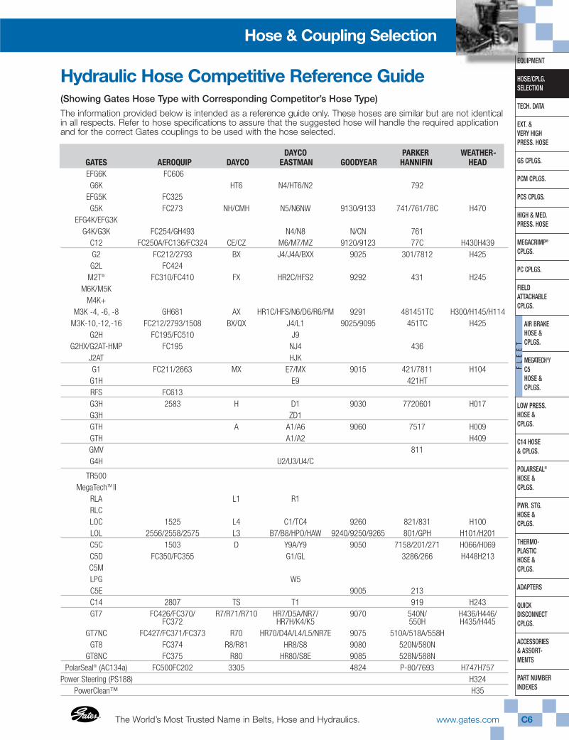
Hydraulic Hose Competitive Reference Guide(Showing Gates Hose Type with Corresponding Competitor’s Hose Type)
The information provided below is intended as a reference guide only. These hoses are similar but are not identicalin all respects. Refer to hose specifications to assure that the suggested hose will handle the required applicationand for the correct Gates couplings to be used with the hose selected.
DAYCO PARKER WEATHER-GATES AEROQUIP DAYCO EASTMAN GOODYEAR HANNIFIN HEADEFG6K FC606G6K HT6 N4/HT6/N2 792
EFG5K FC325G5K FC273 NH/CMH N5/N6NW 9130/9133 741/761/78C H470
EFG4K/EFG3KG4K/G3K FC254/GH493 N4/N8 N/CN 761
C12 FC250A/FC136/FC324 CE/CZ M6/M7/MZ 9120/9123 77C H430H439G2 FC212/2793 BX J4/J4A/BXX 9025 301/7812 H425G2L FC424
M2T® FC310/FC410 FX HR2C/HFS2 9292 431 H245M6K/M5K
M4K+M3K -4, -6, -8 GH681 AX HR1C/HFS/N6/D6/R6/PM 9291 481451TC H300/H145/H114
M3K-10,-12,-16 FC212/2793/1508 BX/QX J4/L1 9025/9095 451TC H425G2H FC195/FC510 J9
G2HX/G2AT-HMP FC195 NJ4 436J2AT HJKG1 FC211/2663 MX E7/MX 9015 421/7811 H104
G1H E9 421HTRFS FC613G3H 2583 H D1 9030 7720601 H017G3H ZD1GTH A A1/A6 9060 7517 H009GTH A1/A2 H409GMV 811G4H U2/U3/U4/C
TR500MegaTechTM II
RLA L1 R1RLCLOC 1525 L4 C1/TC4 9260 821/831 H100LOL 2556/2558/2575 L3 B7/B8/HPO/HAW 9240/9250/9265 801/GPH H101/H201C5C 1503 D Y9A/Y9 9050 7158/201/271 H066/H069C5D FC350/FC355 G1/GL 3286/266 H448H213C5MLPG W5C5E 9005 213C14 2807 TS T1 919 H243GT7 FC426/FC370/ R7/R71/R710 HR7/D5A/NR7/ 9070 540N/ H436/H446/
FC372 HR7H/K4/K5 550H H435/H445GT7NC FC427/FC371/FC373 R70 HR70/D4A/L4/L5/NR7E 9075 510A/518A/558H
GT8 FC374 R8/R81 HR8/S8 9080 520N/580NGT8NC FC375 R80 HR80/S8E 9085 528N/588N
PolarSeal® (AC134a) FC500FC202 3305 4824 P-80/7693 H747H757Power Steering (PS188) H324
PowerClean™ H35
Gates CorporationC7 www.gates.com ®
EQUIPMENT
HOSE/CPLG.SELECTION
TECH. DATA
EXT. & VERY HIGHPRESS. HOSE
GS CPLGS.
PCM CPLGS.
PCS CPLGS.
HIGH & MED.PRESS. HOSE
MEGACRIMP®
CPLGS.
PC CPLGS.
FIELD ATTACHABLECPLGS.
AIR BRAKEHOSE &CPLGS.
MEGATECH®/C5HOSE &CPLGS.
LOW PRESS.HOSE & CPLGS.
C14 HOSE& CPLGS.
POLARSEAL®
HOSE & CPLGS.
PWR. STG.HOSE & CPLGS.
THERMO-PLASTICHOSE & CPLGS.
ADAPTERS
QUICK DISCONNECTCPLGS.
ACCESSORIES& ASSORT-MENTS
PART NUMBERINDEXES
FL
EE
T
Hose & Coupling Selection
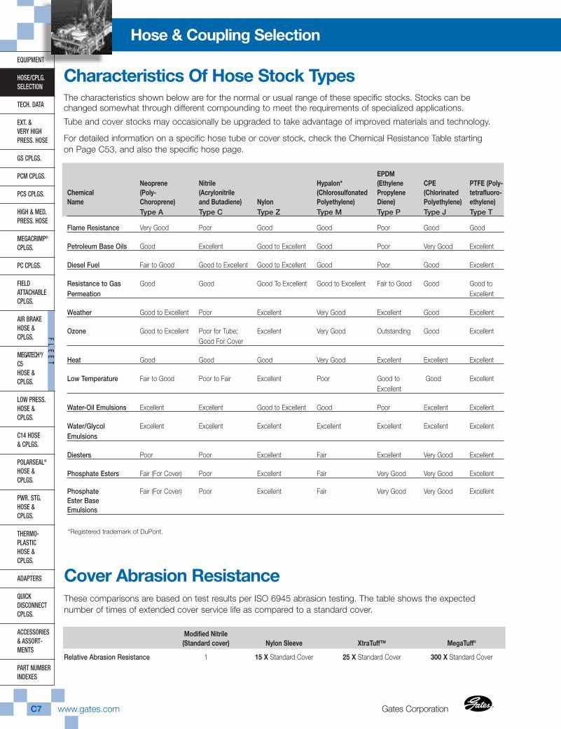
Characteristics Of Hose Stock TypesThe characteristics shown below are for the normal or usual range of these specific stocks. Stocks can bechanged somewhat through different compounding to meet the requirements of specialized applications.
Tube and cover stocks may occasionally be upgraded to take advantage of improved materials and technology.
For detailed information on a specific hose tube or cover stock, check the Chemical Resistance Table startingon Page C53, and also the specific hose page.
EPDMNeoprene Nitrile Hypalon* (Ethylene CPE PTFE (Poly-
Chemical (Poly- (Acrylonitrile (Chlorosulfonated Propylene (Chlorinated tetrafluoro-Name Choroprene) and Butadiene) Nylon Polyethylene) Diene) Polyethylene) ethylene)
Type A Type C Type Z Type M Type P Type J Type T
Flame Resistance Very Good Poor Good Good Poor Good Good
Petroleum Base Oils Good Excellent Good to Excellent Good Poor Very Good Excellent
Diesel Fuel Fair to Good Good to Excellent Good to Excellent Good Poor Good Excellent
Resistance to Gas Good Good Good To Excellent Good to Excellent Fair to Good Good Good to Permeation Excellent
Weather Good to Excellent Poor Excellent Very Good Excellent Good Excellent
Ozone Good to Excellent Poor for Tube; Excellent Very Good Outstanding Good ExcellentGood For Cover
Heat Good Good Good Very Good Excellent Excellent Excellent
Low Temperature Fair to Good Poor to Fair Excellent Poor Good to Good ExcellentExcellent
Water-Oil Emulsions Excellent Excellent Good to Excellent Good Poor Excellent Excellent
Water/Glycol Excellent Excellent Excellent Excellent Excellent Excellent ExcellentEmulsions
Diesters Poor Poor Excellent Fair Excellent Very Good Excellent
Phosphate Esters Fair (For Cover) Poor Excellent Fair Very Good Very Good Excellent
Phosphate Fair (For Cover) Poor Excellent Fair Very Good Very Good ExcellentEster BaseEmulsions
*Registered trademark of DuPont.
Cover Abrasion ResistanceThese comparisons are based on test results per ISO 6945 abrasion testing. The table shows the expectednumber of times of extended cover service life as compared to a standard cover.
Modified Nitrile(Standard cover) Nylon Sleeve XtraTuff™ MegaTuff®
Relative Abrasion Resistance 1 15 X Standard Cover 25 X Standard Cover 300 X Standard Cover
The World’s Most Trusted Name in Belts, Hose and Hydraulics.® www.gates.com C8
EQUIPMENT
HOSE/CPLG.SELECTION
TECH. DATA
EXT. & VERY HIGHPRESS. HOSE
GS CPLGS.
PCM CPLGS.
PCS CPLGS.
HIGH & MED.PRESS. HOSE
MEGACRIMP®
CPLGS.
PC CPLGS.
FIELD ATTACHABLECPLGS.
AIR BRAKEHOSE & CPLGS.
MEGATECH®/C5HOSE & CPLGS.
LOW PRESS.HOSE & CPLGS.
C14 HOSE& CPLGS.
POLARSEAL®
HOSE & CPLGS.
PWR. STG.HOSE & CPLGS.
THERMO-PLASTICHOSE & CPLGS.
ADAPTERS
QUICK DISCONNECTCPLGS.
ACCESSORIES& ASSORT-MENTS
PART NUMBERINDEXES
FL
EE
T
Hose & Coupling Selection
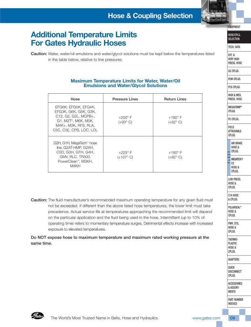
Additional Temperature Limits For Gates Hydraulic HosesCaution: Water, water/oil emulsions and water/glycol solutions must be kept below the temperatures listed
in the table below, relative to line pressures.
Caution: The fluid manufacturer’s recommended maximum operating temperature for any given fluid mustnot be exceeded. If different than the above listed hose temperatures, the lower limit must takeprecedence. Actual service life at temperatures approaching the recommended limit will dependon the particular application and the fluid being used in the hose. Intermittent (up to 10% ofoperating time) refers to momentary temperature surges. Detrimental effects increase with increasedexposure to elevated temperatures.
Do NOT expose hose to maximum temperature and maximum rated working pressure at thesame time.
Maximum Temperature Limits for Water, Water/Oil Emulsions and Water/Glycol Solutions
Hose
EFG6K, EFG5K, EFG4K,EFG3K, G6K, G5K, G3K,C12, G2, G2L, MCPB+,G1, M2T®, M6K, M5K,
M4K+, M3K, RFS, RLA,C5C, C5E, CPS, LOC, LOL
G2H, G1H, MegaTech™ hoseline, G2AT-HMP, G2XH,C5D, G3H, GTH, G4H,
GMV, RLC, TR500,PowerClean™, M3KH,
M4KH
Pressure Lines
+200° F(+93° C)
+225° F(+107° C)
Return Lines
+180° F(+82° C)
+180° F(+82° C)
Gates CorporationC9 www.gates.com ®
EQUIPMENT
HOSE/CPLG.SELECTION
TECH. DATA
EXT. & VERY HIGHPRESS. HOSE
GS CPLGS.
PCM CPLGS.
PCS CPLGS.
HIGH & MED.PRESS. HOSE
MEGACRIMP®
CPLGS.
PC CPLGS.
FIELD ATTACHABLECPLGS.
AIR BRAKEHOSE &CPLGS.
MEGATECH®/C5HOSE &CPLGS.
LOW PRESS.HOSE & CPLGS.
C14 HOSE& CPLGS.
POLARSEAL®
HOSE & CPLGS.
PWR. STG.HOSE & CPLGS.
THERMO-PLASTICHOSE & CPLGS.
ADAPTERS
QUICK DISCONNECTCPLGS.
ACCESSORIES& ASSORT-MENTS
PART NUMBERINDEXES
FL
EE
T
Hose & Coupling Selection
(R) SELECTION, INSTALLATION AND MAINTENANCEOF HOSE AND HOSE ASSEMBLIES—SAE J1273 OCT96 SAE Recommended Practice
Report of the Fluid Conductors and Connectors Technical Committee, approved September 1979 and reaffirmedMay 1986. Completely revised by the SAE Fluid Conductors and Connectors Technical Committee SC2—Hydraulic Hose and Hose Fittings October 1996. Rationale statement available.
1. ScopeHose (also includes hose assemblies) has a finite lifeand there are a number of factors which will reduce itslife. This SAE recommended practice is intended as aguide to assist system designers and/or users in theselection, installation, and maintenance of hose. Thedesigners and users must make a systematic review ofeach application and then select, install, and maintainthe hose to fulfill the requirements of the application.The following are general guidelines and are not nec-essarily a complete list.
WARNING—IMPROPER SELECTION, INSTALLATION,OR MAINTENANCE MAY RESULT IN PREMATUREFAILURES, BODILY INJURY, OR PROPERTY DAMAGE.
2. References
2.1 Applicable Documents
The following publications form a part of this specifica-tion to the extent specified herein. The latest issue ofSAE publications shall apply.
2.1.1 SAE PUBLICATIONS — Available fromSAE, 400 Commonwealth Drive, Warrendale, PA15096-0001.
J516—Hydraulic Hose Fittings J517—Hydraulic Hose
3. Selection
The following is a list of factors which must beconsidered before final hose selection can be made:
3.1 Pressure
After determining the system pressure, hose selectionmust be made so that the recommended maximumoperating pressure is equal to or greater than thesystem pressure. Surge pressures higher than themaximum operating pressure will shorten hose life andmust be taken into account by the hydraulic designer.
3.2 Suction
Hoses used for suction applications must be selectedto ensure the hose will withstand the negative pressureof the system.
3.3 Temperature
Care must be taken to ensure that fluid and ambienttemperatures, both static and transient, do not exceedthe limitations of the hose. Special care must be takenwhen routing near hot manifolds.
3.4 Fluid Compatibility
Hose selection must assure compatibility of thehose tube, cover, and fittings with the fluid used.Additional caution must be observed in hose selectionfor gaseous applications.
3.5 Size
Transmission of power by means of pressurized fluidvaries with pressure and rate of flow. The size of thecomponents must be adequate to keep pressurelosses to a minimum and avoid damage to the hosedue to heat generation or excessive turbulence.
3.6 Routing
Attention must be given to optimum routing tominimize inherent problems.
3.7 Environment
Care must be taken to ensure that the hose andfittings are either compatible with or protected fromthe environment to which they are exposed.Environmental conditions such as ultraviolet light,ozone, salt water, chemicals, and air pollutantscan cause degradation and premature failure and,therefore, must be considered.
The World’s Most Trusted Name in Belts, Hose and Hydraulics.®
®
www.gates.com C10
EQUIPMENT
HOSE/CPLG.SELECTION
TECH. DATA
EXT. & VERY HIGHPRESS. HOSE
GS CPLGS.
PCM CPLGS.
PCS CPLGS.
HIGH & MED.PRESS. HOSE
MEGACRIMP®
CPLGS.
PC CPLGS.
FIELD ATTACHABLECPLGS.
AIR BRAKEHOSE & CPLGS.
MEGATECH®/ C5HOSE & CPLGS.
LOW PRESS.HOSE & CPLGS.
C14 HOSE& CPLGS.
POLARSEAL®
HOSE & CPLGS.
PWR. STG.HOSE & CPLGS.
THERMO-PLASTICHOSE & CPLGS.
ADAPTERS
QUICK DISCONNECTCPLGS.
ACCESSORIES& ASSORT-MENTS
PART NUMBERINDEXES
FL
EE
T
Hose & Coupling Selection
3.8 Mechanical Loads
External forces can significantly reduce hose life.Mechanical loads which must be considered includeexcessive flexing, twisting, kinking, tensile or sideloads, bend radius, and vibration. Use of swivel typefittings or adapters may be required to ensure no twistis put into the hose. Unusual applications may requirespecial testing prior to hose selection.
3.9 Abrasion
While a hose is designed with a reasonable level ofabrasion resistance, care must be taken to protectthe hose from excessive abrasion which can resultin erosion, snagging, and cutting of the hose cover.Exposure of the reinforcement will significantly acceler-ate hose failure.
3.10 Proper End Fitting
Care must be taken to ensure proper compatibilityexists between the hose and coupling selected basedon the manufacturer’s recommendations substantiatedby testing to industry standards such as SAE J517. Endfitting components from one manufacturer are usuallynot compatible with end fitting components supplied byanother manufacturer (i.e., using a hose fitting nipplefrom one manufacturer with a hose socket from anothermanufacturer). It is the responsibility of the fabricatorto consult the manufacturer’s written instruction or themanufacturer directly for proper end fitting componentry.
3.11 Length
When establishing proper hose length, motion absorp-tion, hose length changes due to pressure, as well ashose and machine tolerances must be considered.
3.12 Specifications and Standards
When selecting hose, government, industry, and manu-facturers’ specifications and recommendations must bereviewed as applicable.
3.13 Hose Cleanliness
Hose components vary in cleanliness levels. Care mustbe taken to ensure that the assemblies selected havean adequate level of cleanliness for the application.
3.14 Electrical Conductivity
Certain applications require that hose be non-conduc-tive to prevent electrical current flow. Other applicationsrequire the hose to be sufficiently conductive to drainoff static electricity. Hose and fittings must be chosenwith these needs in mind.
4. InstallationAfter selection of proper hose, the following factorsmust be considered by the installer.
4.1 Pre-Installation Inspection
Prior to installation, a careful examination of the hosemust be performed. All components must be checkedfor correct style, size, and length. In addition, the hosemust be examined for cleanliness, I.D. obstructions, blisters, loose cover, or any other visible defects.
4.2 Follow Manufacturers’ AssemblyInstructions
Hose assemblies may be fabricated by the manufactur-er, an agent for or customer of the manufacturer, or bythe user. Fabrication of permanently attached fittingsto hydraulic hose requires specialized assembly equip-ment. Field-attachable fittings (screw style and segmentclamp style) can usually be assembled without special-ized equipment, although many manufacturers provideequipment to assist in this operation. SAE J517 hosefrom one manufacturer is usually not compatible withSAE J516 fittings supplied by another manufacturer.It is the responsibility of the fabricator to consult themanufacturer’s written assembly instructions or themanufacturers directly before intermixing hose andfittings from two manufacturers. Similarly, assemblyequipment from one manufacturer is usually not inter-changeable with that of another manufacturer. It is theresponsibility of the fabricator to consult the manufac-turer’s written instructions or the manufacturer directlyfor proper assembly equipment. Always follow themanufacturer’s instructions for proper preparation andfabrication of hose assemblies.
4.3 Minimum Bend Radius
Installation at less than minimum bend radius may signifi-cantly reduce hose life. Particular attention must be givento preclude sharp bending at the hose/fitting juncture.
Gates CorporationC11 www.gates.com ®
®
EQUIPMENT
HOSE/CPLG.SELECTION
TECH. DATA
EXT. & VERY HIGHPRESS. HOSE
GS CPLGS.
PCM CPLGS.
PCS CPLGS.
HIGH & MED.PRESS. HOSE
MEGACRIMP®
CPLGS.
PC CPLGS.
FIELD ATTACHABLECPLGS.
AIR BRAKEHOSE &CPLGS.
MEGATECH®/C5HOSE &CPLGS.
LOW PRESS.HOSE & CPLGS.
C14 HOSE& CPLGS.
POLARSEAL®
HOSE & CPLGS.
PWR. STG.HOSE & CPLGS.
THERMO-PLASTICHOSE & CPLGS.
ADAPTERS
QUICK DISCONNECTCPLGS.
ACCESSORIES& ASSORT-MENTS
PART NUMBERINDEXES
FL
EE
T
Hose & Coupling Selection
4.4 Twist Angle and Orientation
Hose installations must be such that relative motionof machine components produces bending of thehose rather than twisting.
4.5 Securement
In many applications, it may be necessary to restrain,protect, or guide the hose to protect it from damageby unnecessary flexing, pressure surges, and contactwith other mechanical components. Care must betaken to ensure such restraints do not introduce addi-tional stress or wear points.
4.6 Proper Connection of Ports
Proper physical installation of the hose requires acorrectly installed port connection while ensuringthat no twist or torque is put into the hose.
4.7 Avoid External Damage
Proper installation is not complete without ensuringthat tensile loads, side loads, kinking, flattening,potential abrasion, thread damage, or damage tosealing surfaces are corrected or eliminated.
4.8 System Check Out
After completing the installation, all air entrapmentmust be eliminated, and the system pressurized tothe maximum system pressure and checked forproper function and freedom from leaks.
NOTE—Avoid potential hazardous areas while testing.
5. MaintenanceEven with proper selection and installation, hose lifemay be significantly reduced without a continuingmaintenance program.
Frequency should be determined by the severity of theapplication and risk potential. A maintenance programshould include the following as a minimum:
5.1 Hose Storage
Hose products in storage can be affected adverselyby temperature, humidity, ozone, sunlight, oils,solvents, corrosive liquids and fumes, insects, rodents,and radioactive materials. Storage areas should berelatively cool and dark and free of dust, dirt, damp-ness, and mildew.
5.2 Visual Inspections
Any of the following conditions requires replacementof the hose:
a. Leaks at fitting or in hose. (Leaking fluid is afire hazard.)
b. Damaged, cut, or abraded cover. (Any reinforce-ment exposed.)
c. Kinked, crushed, flattened, or twisted hose.
d. Hard, stiff, heat cracked, or charred hose.
e. Blistered, soft, degraded, or loose cover.
f. Cracked, damaged, or badly corroded fittings.
g. Fitting slippage on hose.
5.3 Visual Inspections
The following items must be tightened, repaired,or replaced as required:
a. Leaking port conditions.
b. Clamps, guards, shields.
c. System fluid level, fluid type, and any air entrapment.
5.4 Functional Test
Operate the system at maximum operating pressureand check for possible malfunctions and freedomfrom leaks.
NOTE—Avoid potential hazardous areas while testing.
5.5 Replacement Intervals
Specific replacement intervals must be consideredbased on previous service life, government or industryrecommendations, or when failures could result inunacceptable down time, damage, or injury risk.
The World’s Most Trusted Name in Belts, Hose and Hydraulics.®
®
www.gates.com C12
EQUIPMENT
HOSE/CPLG.SELECTION
TECH. DATA
EXT. & VERY HIGHPRESS. HOSE
GS CPLGS.
PCM CPLGS.
PCS CPLGS.
HIGH & MED.PRESS. HOSE
MEGACRIMP®
CPLGS.
PC CPLGS.
FIELD ATTACHABLECPLGS.
AIR BRAKEHOSE & CPLGS.
MEGATECH®/ C5HOSE & CPLGS.
LOW PRESS.HOSE & CPLGS.
C14 HOSE& CPLGS.
POLARSEAL®
HOSE & CPLGS.
PWR. STG.HOSE & CPLGS.
THERMO-PLASTICHOSE & CPLGS.
ADAPTERS
QUICK DISCONNECTCPLGS.
ACCESSORIES& ASSORT-MENTS
PART NUMBERINDEXES
FL
EE
T
Hose & Coupling Selection
What is FMVSS-106?The standard is written with specifics on labeling, perform-ance tests, tests procedures, and registration. It is not astandard for design specifications for motor vehicle brakehose, brake hose assemblies, or brake hose end fittings.The Standard No. 106 will ensure that each user of brakehose will be supplied only the highest quality of hose.DOT will conduct random performance testing in accor-dance with the test procedures to ensure that the hoses,couplings, and assemblies meet FMVSS 106.
“The purpose of the standard is to reduce deaths andinjuries occurring as a result of brake system failure frompressure or vacuum loss due to hose or hose assemblyrupture.” The regulations will apply to all over-the-roadvehicles including trailers and motorcycles. Off–the-roadvehicles will not be regulated if they are designed tooperate on those other than public roads.
Basic Provisions of FMVSS-106.1. Three types of brake hose are covered (hydraulic, air,
and vacuum brake) together with couplings and hoseassemblies. At this point, we will only focus on airbrake hose and assemblies.
2. Performance level for brake hose is establishedinstead of design specifications.
3. Permanent as well as reusable fittings are permissiblewith air brake hose. Inside and outside diametersstandards for air brake hose intended for use withfield attachable couplings have been established.These hoses are identified as Type I and Type II.
Gates’ Customer/Assembler with Regard to FMVSS-106.1. Testing (dimensional & pressure tested) each assemblyor per customer’s requirements before it is packaged anddelivered to their customer.
2. Two of every 100 air brake hose assemblies producedor per customer’s requirements are subjected to hydrostaticpressure testing and tensile strength (destructive) testing.
Labeling of Air Brake Hose.Any customer crimping air brake assemblies must beregistered with the National Traffic Safety Administration(NHTSA).
The National Highway Traffic SafetyAdministration (NHTSA) requires:1. Product DOT CERTIFICATION. (Gates Corporation
responsibility. The Gates Logo is our DOT registration.)
2. Registration of the assembler. (Customer/Distributorresponsibility.)*
3. Permanent assembly identification. (Customer/Distributor responsibility.) Refer to Gates frosted airbrake hose labels below.
* To begin the registration process, please complete theBRAKE HOSE REGISTRATION application form on thefollowing page. You can mail or fax the completed formto the address and number listed on the form.
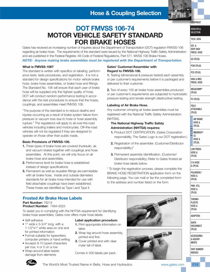
• Self-adhesive• 1" wide x 3-3/4" long, with a
1-1/2"x1" white area on one endfor printed information
• Format suitable for typewriters,computer printers or hand writing
• Accepts 9-10 typed charactersper row, 4 or 5 on a row
• Wrap-around label resists damage from elements
Label application procedure:1. Print appropriate information on
label.2. Wrap tag around hose assembly,
printed end first.3. Cover printed end with clear
mylar tail of label.
Comes in 500 labels per pack.
Frosted Air Brake Hose LabelsPart Number: 78214Product Number: 7484-0023
To assist you in complying with the NHTSA requirement for identifyingbrake hose assemblies, Gates now offers mylar hose labels.
DOT FMVSS 106-74MOTOR VEHICLE SAFETY STANDARD
FOR BRAKE HOSESGates has received an increasing number of inquiries about the Department of Transportation (DOT) regulation FMVSS-106regarding air brake hose. The requirements of the standard were issued by the National Highway Traffic Safety Administrationand are published in the Federal Register, 49 Code of Federal Regulations, Part 571. MVSS 106 Brake Hoses.NOTE: Anyone making brake assemblies must be registered with the Department of Transportation.
Gates CorporationC13 www.gates.com ®
®
EQUIPMENT
HOSE/CPLG.SELECTION
TECH. DATA
EXT. & VERY HIGHPRESS. HOSE
GS CPLGS.
PCM CPLGS.
PCS CPLGS.
HIGH & MED.PRESS. HOSE
MEGACRIMP®
CPLGS.
PC CPLGS.
FIELD ATTACHABLECPLGS.
AIR BRAKEHOSE &CPLGS.
MEGATECH®/C5HOSE &CPLGS.
LOW PRESS.HOSE & CPLGS.
C14 HOSE& CPLGS.
POLARSEAL®
HOSE & CPLGS.
PWR. STG.HOSE & CPLGS.
THERMO-PLASTICHOSE & CPLGS.
ADAPTERS
QUICK DISCONNECTCPLGS.
ACCESSORIES& ASSORT-MENTS
PART NUMBERINDEXES
FL
EE
T
Hose & Coupling Selection
Brake Hose Registration Application“PLEASE TYPE or PRINT CLEARLY” AND SUBMIT BRAKE HOSE APPLICATION TO: JEANETTE GREENFIELDAT THE FOLLOWING NATIONAL HIGHWAY TRAFFIC SAFETY ADMINISTRATION (NHTSA) ADDRESS:
Jeanette GreenfieldOffice of Vehicle Safety Compliance400 Seventh Street, S.W. NSA-32Washington, DC 20590Phone (202) 366-5317Fax (202) 366-1024www.nhtsa.dot.gov
DATE:____________________________
BRAKE HOSE MANUFACTURER’S ADDRESS
Plant Name:____________________________________________________________________
Post Office Box No.:_____________________________________________________________
Street:_________________________________________________________________________
City:___________________________________________________________________________
* DESIGNATION SYMBOL (s):____________________________
State (Province):_________________________________________________________________
Country:________________________________________________________________________
Zip Code:_______________________________________________________________________
Plant Contact Person:____________________________________________________________
Phone Number:_________________________________________________________________
Fax Number:____________________________________________________________________
** (COMPLETE ONLY IF THIS IS A FOREIGN MANUFACTURER) BRAKE HOSE MANUFACTURER’S US AGENT
Agent Name:____________________________________________________________________
Post Office Box No.:_____________________________________________________________
Street:__________________________________________________________________________
City:___________________________________________________________________________
State:__________________________________________________________________________
Country:________________________________________________________________________
Zip Code:_______________________________________________________________________
Agent Contact Person____________________________________________________________
Agent Fax Number_______________________________________________________________
Agent Phone Number:____________________________________________________________
* DESIGNATION SYMBOL(s): May consist of block capital letters, numerals or a symbol.
The World’s Most Trusted Name in Belts, Hose and Hydraulics.®
®
www.gates.com C14
EQUIPMENT
HOSE/CPLG.SELECTION
TECH. DATA
EXT. & VERY HIGHPRESS. HOSE
GS CPLGS.
PCM CPLGS.
PCS CPLGS.
HIGH & MED.PRESS. HOSE
MEGACRIMP®
CPLGS.
PC CPLGS.
FIELD ATTACHABLECPLGS.
AIR BRAKEHOSE & CPLGS.
MEGATECH®/ C5HOSE & CPLGS.
LOW PRESS.HOSE & CPLGS.
C14 HOSE& CPLGS.
POLARSEAL®
HOSE & CPLGS.
PWR. STG.HOSE & CPLGS.
THERMO-PLASTICHOSE & CPLGS.
ADAPTERS
QUICK DISCONNECTCPLGS.
ACCESSORIES& ASSORT-MENTS
PART NUMBERINDEXES
FL
EE
T
Hose & Coupling Selection
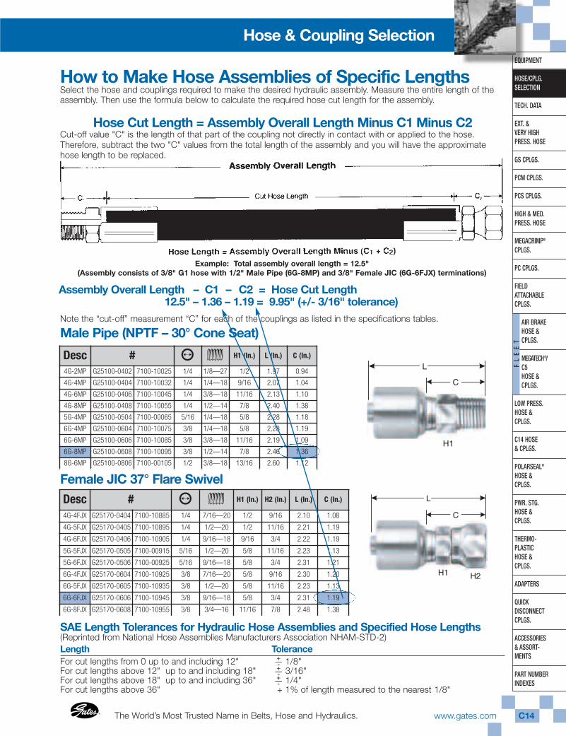
Example: Total assembly overall length = 12.5"(Assembly consists of 3/8" G1 hose with 1/2" Male Pipe (6G-8MP) and 3/8" Female JIC (6G-6FJX) terminations)
How to Make Hose Assemblies of Specific LengthsSelect the hose and couplings required to make the desired hydraulic assembly. Measure the entire length of the assembly. Then use the formula below to calculate the required hose cut length for the assembly.
Hose Cut Length = Assembly Overall Length Minus C1 Minus C2Cut-off value "C" is the length of that part of the coupling not directly in contact with or applied to the hose.Therefore, subtract the two "C" values from the total length of the assembly and you will have the approximatehose length to be replaced.
Note the “cut-off” measurement “C” for each of the couplings as listed in the specifications tables.
12.5" – 1.36 – 1.19 = 9.95" (+/- 3/16" tolerance)
Male Pipe (NPTF – 30° Cone Seat)
Female JIC 37° Flare Swivel
Desc # ⁄ ¤ H1 (In.) L (In.) C (In.)
4G-2MP G25100-0402 7100-10025 1/4 1/8—27 1/2 1.97 0.94
4G-4MP G25100-0404 7100-10032 1/4 1/4—18 9/16 2.07 1.04
4G-6MP G25100-0406 7100-10045 1/4 3/8—18 11/16 2.13 1.10
4G-8MP G25100-0408 7100-10055 1/4 1/2—14 7/8 2.40 1.38
5G-4MP G25100-0504 7100-00065 5/16 1/4—18 5/8 2.28 1.18
6G-4MP G25100-0604 7100-10075 3/8 1/4—18 5/8 2.28 1.19
6G-6MP G25100-0606 7100-10085 3/8 3/8—18 11/16 2.19 1.09
6G-8MP G25100-0608 7100-10095 3/8 1/2—14 7/8 2.46 1.36
8G-6MP G25100-0806 7100-00105 1/2 3/8—18 13/16 2.60 1.12
Desc # ⁄ ¤ H1 (In.) H2 (In.) L (In.) C (In.)
4G-4FJX G25170-0404 7100-10885 1/4 7/16—20 1/2 9/16 2.10 1.08
4G-5FJX G25170-0405 7100-10895 1/4 1/2—20 1/2 11/16 2.21 1.19
4G-6FJX G25170-0406 7100-10905 1/4 9/16—18 9/16 3/4 2.22 1.19
5G-5FJX G25170-0505 7100-00915 5/16 1/2—20 5/8 11/16 2.23 1.13
5G-6FJX G25170-0506 7100-00925 5/16 9/16—18 5/8 3/4 2.31 1.21
6G-4FJX G25170-0604 7100-10925 3/8 7/16—20 5/8 9/16 2.30 1.20
6G-5FJX G25170-0605 7100-10935 3/8 1/2—20 5/8 11/16 2.23 1.13
6G-6FJX G25170-0606 7100-10945 3/8 9/16—18 5/8 3/4 2.31 1.19
6G-8FJX G25170-0608 7100-10955 3/8 3/4—16 11/16 7/8 2.48 1.38
SAE Length Tolerances for Hydraulic Hose Assemblies and Specified Hose Lengths(Reprinted from National Hose Assemblies Manufacturers Association NHAM-STD-2) Length ToleranceFor cut lengths from 0 up to and including 12" 1/8" For cut lengths above 12" up to and including 18" 3/16" For cut lengths above 18" up to and including 36" 1/4" For cut lengths above 36" + 1% of length measured to the nearest 1/8"
H2H1
C
L
H1
C
L
Assembly Overall Length – C1 – C2 = Hose Cut Length
+—-+—-+—-
Gates CorporationC15 www.gates.com ®
®
EQUIPMENT
HOSE/CPLG.SELECTION
TECH. DATA
EXT. & VERY HIGHPRESS. HOSE
GS CPLGS.
PCM CPLGS.
PCS CPLGS.
HIGH & MED.PRESS. HOSE
MEGACRIMP®
CPLGS.
PC CPLGS.
FIELD ATTACHABLECPLGS.
AIR BRAKEHOSE &CPLGS.
MEGATECH®/C5HOSE &CPLGS.
LOW PRESS.HOSE & CPLGS.
C14 HOSE& CPLGS.
POLARSEAL®
HOSE & CPLGS.
PWR. STG.HOSE & CPLGS.
THERMO-PLASTICHOSE & CPLGS.
ADAPTERS
QUICK DISCONNECTCPLGS.
ACCESSORIES& ASSORT-MENTS
PART NUMBERINDEXES
FL
EE
T
Hose & Coupling Selection
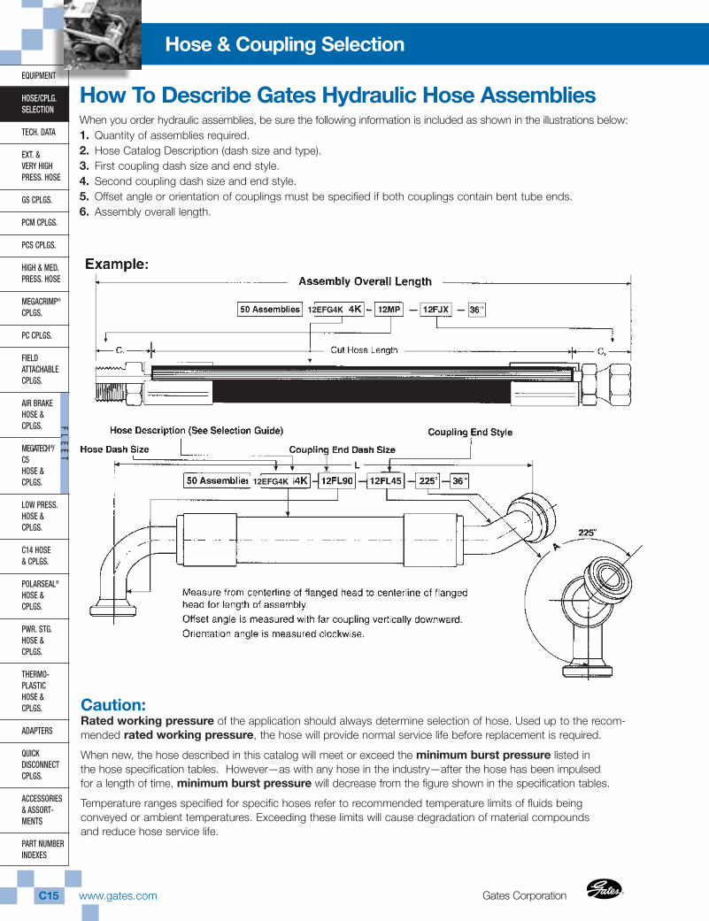
How To Describe Gates Hydraulic Hose AssembliesWhen you order hydraulic assemblies, be sure the following information is included as shown in the illustrations below:1. Quantity of assemblies required.2. Hose Catalog Description (dash size and type).3. First coupling dash size and end style.4. Second coupling dash size and end style.5. Offset angle or orientation of couplings must be specified if both couplings contain bent tube ends.6. Assembly overall length.
Caution:Rated working pressure of the application should always determine selection of hose. Used up to the recom-mended rated working pressure, the hose will provide normal service life before replacement is required.
When new, the hose described in this catalog will meet or exceed the minimum burst pressure listed inthe hose specification tables. However—as with any hose in the industry—after the hose has been impulsedfor a length of time, minimum burst pressure will decrease from the figure shown in the specification tables.
Temperature ranges specified for specific hoses refer to recommended temperature limits of fluids beingconveyed or ambient temperatures. Exceeding these limits will cause degradation of material compoundsand reduce hose service life.
12EFG4K
12EFG4K
The World’s Most Trusted Name in Belts, Hose and Hydraulics.®
®
www.gates.com C16
EQUIPMENT
HOSE/CPLG.SELECTION
TECH. DATA
EXT. & VERY HIGHPRESS. HOSE
GS CPLGS.
PCM CPLGS.
PCS CPLGS.
HIGH & MED.PRESS. HOSE
MEGACRIMP®
CPLGS.
PC CPLGS.
FIELD ATTACHABLECPLGS.
AIR BRAKEHOSE & CPLGS.
MEGATECH®/ C5HOSE & CPLGS.
LOW PRESS.HOSE & CPLGS.
C14 HOSE& CPLGS.
POLARSEAL®
HOSE & CPLGS.
PWR. STG.HOSE & CPLGS.
THERMO-PLASTICHOSE & CPLGS.
ADAPTERS
QUICK DISCONNECTCPLGS.
ACCESSORIES& ASSORT-MENTS
PART NUMBERINDEXES
FL
EE
T
Hose & Coupling Selection
180°
0°
270°90°
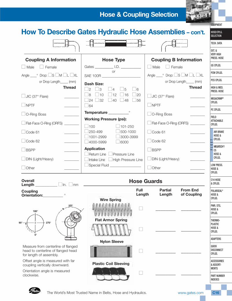
Coupling A Information
■■ Male ■■ Female
Angle ____° Drop: ■■S ■■M ■■L ■■XL
or Drop Length_____ (mm)
Thread
■■ JIC (37° Flare) ________
■■NPTF ________
■■O-Ring Boss ________
■■Flat-Face O-Ring (ORFS) ________
■■Code 61 ________
■■Code 62 ________
■■BSPP ________
■■DIN (Light/Heavy) ________
■■Other ________
Hose TypeGates __________ I.D. ___________
orSAE 100R _____________________
Dash Size:■■2 ■■3 ■■4 ■■5 ■■6
■■8 ■■10 ■■12 ■■16 ■■20
■■24 ■■32 ■■40 ■■48 ■■56
■■64
Temperature ___________°
Working Pressure (psi):
■■100 ■■101-250■■250-499 ■■500-1000 ■■1001-2999 ■■3000-3999■■4000-5999 ■■6000
Application■■Return Line ■■Pressure Line
■■ Intake Line ■■High Pressure Line
■■Special Fluid _________________
Coupling B Information
■■ Male ■■ Female
Angle ____° Drop: ■■S ■■M ■■L ■■XL
or Drop Length_____ (mm)
Thread
■■ JIC (37° Flare) ________
■■NPTF ________
■■O-Ring Boss ________
■■Flat-Face O-Ring (ORFS) ________
■■Code 61 ________
■■Code 62 ________
■■BSPP ________
■■DIN (Light/Heavy) ________
■■Other ________
OverallLength ____________ ■■ In. ■■mm
CouplingOrientation:___________ °
Measure from centerline of flangedhead to centerline of flanged headfor length of assembly.
Offset angle is measured with farcoupling vertically downward.
Orientation angle is measuredclockwise.
Hose Guards
FullLength
PartialLength
From Endof Coupling
■■ ________ ________
■■ ________ ________
■■ ________ ________
■■ ________ ________
Wire Spring
Flat Armor Spring
Nylon Sleeve
Plastic Coil Sleeving
How To Describe Gates Hydraulic Hose Assemblies – con’t.

Gates CorporationC17 www.gates.com ®
®
EQUIPMENT
HOSE/CPLG.SELECTION
TECH. DATA
EXT. & VERY HIGHPRESS. HOSE
GS CPLGS.
PCM CPLGS.
PCS CPLGS.
HIGH & MED.PRESS. HOSE
MEGACRIMP®
CPLGS.
PC CPLGS.
FIELD ATTACHABLECPLGS.
AIR BRAKEHOSE &CPLGS.
MEGATECH®/C5HOSE &CPLGS.
LOW PRESS.HOSE & CPLGS.
C14 HOSE& CPLGS.
POLARSEAL®
HOSE & CPLGS.
PWR. STG.HOSE & CPLGS.
THERMO-PLASTICHOSE & CPLGS.
ADAPTERS
QUICK DISCONNECTCPLGS.
ACCESSORIES& ASSORT-MENTS
PART NUMBERINDEXES
FL
EE
T
Hose & Coupling Selection
Proper hose installation is essential for satisfactoryperformance. If hose length is excessive, theappearance of the installation will be unsatisfactoryand unnecessary cost of equipment will be involved.If hose assemblies are too short to permit adequateflexing and changes in length due to expansion orcontraction, hose service life will be reduced.
The following diagrams show proper hoseinstallations which provide maximum performanceand cost savings. Consider these examples indetermining length of a specific assembly.
When hose installation is straight, allow enough slack inhose line to provide for length changes which will occurwhen pressure is applied.
Adequate hose length is necessary to distribute movementon flexing applications and to avoid abrasion.
Avoid twisting of hose lines bent in two planes by clampinghose at change of plane.
Reduce number of pipe thread joints by using hydraulicadapters instead of pipe fittings.
When radius is below the required minimum, use an angleadapter to avoid sharp bends.
Use proper angle adapters to avoid tight bend in hose.
Prevent twisting and distortion by bending hose in sameplane as the motion of the port to which hose is connected.
Route hose directly by using 45° and/or 90° adapter and fit-tings. Avoid excessive hose length to improve appearance.
Note: To allow for length changes when hose is pressurized,do not clamp at bends so that curves will absorb changes.Do not clamp high and low pressure lines together.
WRONG
HIGH PRESSURE
NO PRESSURE
Hose Assembly Routing Tips
The World’s Most Trusted Name in Belts, Hose and Hydraulics.®
®
www.gates.com C18
Hose & Coupling SelectionEQUIPMENT
HOSE/CPLG.SELECTION
TECH. DATA
EXT. & VERY HIGHPRESS. HOSE
GS CPLGS.
PCM CPLGS.
PCS CPLGS.
HIGH & MED.PRESS. HOSE
MEGACRIMP®
CPLGS.
PC CPLGS.
FIELD ATTACHABLECPLGS.
AIR BRAKEHOSE & CPLGS.
MEGATECH®/ C5HOSE & CPLGS.
LOW PRESS.HOSE & CPLGS.
C14 HOSE& CPLGS.
POLARSEAL®
HOSE & CPLGS.
PWR. STG.HOSE & CPLGS.
THERMO-PLASTICHOSE & CPLGS.
ADAPTERS
QUICK DISCONNECTCPLGS.
ACCESSORIES& ASSORT-MENTS
PART NUMBERINDEXES
FL
EE
T
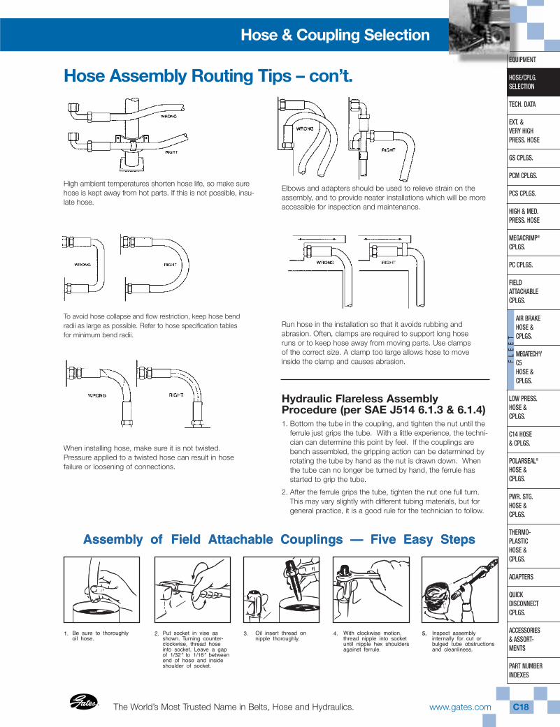
Hose Assembly Routing Tips – con’t.
High ambient temperatures shorten hose life, so make surehose is kept away from hot parts. If this is not possible, insu-late hose.
To avoid hose collapse and flow restriction, keep hose bendradii as large as possible. Refer to hose specification tablesfor minimum bend radii.
When installing hose, make sure it is not twisted.Pressure applied to a twisted hose can result in hosefailure or loosening of connections.
Elbows and adapters should be used to relieve strain on theassembly, and to provide neater installations which will be moreaccessible for inspection and maintenance.
Run hose in the installation so that it avoids rubbing andabrasion. Often, clamps are required to support long hoseruns or to keep hose away from moving parts. Use clampsof the correct size. A clamp too large allows hose to moveinside the clamp and causes abrasion.
Hydraulic Flareless AssemblyProcedure (per SAE J514 6.1.3 & 6.1.4)1. Bottom the tube in the coupling, and tighten the nut until the
ferrule just grips the tube. With a little experience, the techni-cian can determine this point by feel. If the couplings arebench assembled, the gripping action can be determined byrotating the tube by hand as the nut is drawn down. Whenthe tube can no longer be turned by hand, the ferrule hasstarted to grip the tube.
2. After the ferrule grips the tube, tighten the nut one full turn.This may vary slightly with different tubing materials, but forgeneral practice, it is a good rule for the technician to follow.
Gates CorporationC19 www.gates.com ®
®
EQUIPMENT
HOSE/CPLG.SELECTION
TECH. DATA
EXT. & VERY HIGHPRESS. HOSE
GS CPLGS.
PCM CPLGS.
PCS CPLGS.
HIGH & MED.PRESS. HOSE
MEGACRIMP®
CPLGS.
PC CPLGS.
FIELD ATTACHABLECPLGS.
AIR BRAKEHOSE &CPLGS.
MEGATECH®/C5HOSE &CPLGS.
LOW PRESS.HOSE & CPLGS.
C14 HOSE& CPLGS.
POLARSEAL®
HOSE & CPLGS.
PWR. STG.HOSE & CPLGS.
THERMO-PLASTICHOSE & CPLGS.
ADAPTERS
QUICK DISCONNECTCPLGS.
ACCESSORIES& ASSORT-MENTS
PART NUMBERINDEXES
FL
EE
T
Hose & Coupling Selection
Coupling SelectionEnd Configuration Selection
It is important to keep in mind that thehose assembly (coupling and hose) isonly one component of the system. Inchoosing the correct end terminationsfor the couplings attached to the hose,formal design standards and soundengineering judgement should be used.
In the absence of formal design stan-dards, consider the following factors inchoosing the proper end termination:
■ Pressure
■ Impulse frequency,amplitude and wave form
■ Vibration
■ Corrosion
■ Dissimilar metals (galvaniccorrosion)
■ Maintenance proceduresand frequency
■ Installation reliability
■ Connection’s risk in the system
■ Exposure to the elements
■ Operator’s and/or bystander’sexposure to the connection
■ Installation, operation andservice activities and practicesthat affect safety
If there are any questions as to whatend fittings should be used, Gatesrecommends that you consult your fieldsales representative or the Gates Hoseand Connector Product ApplicationGroup for assistance.
Stem and Ferrule Selection
Choosing the proper stem and ferruledepends on the specific hose and ter-mination to be used in the assembly.Check the Gates Crimp Data manual,Literature No. 428-7365 (Auto.)/35019(Ind.), to ensure proper hose assemblycomponents and crimp specification.
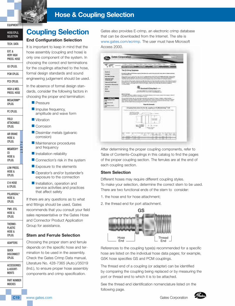
Gates also provides E-crimp, an electronic crimp databasethat can be downloaded from the Internet. The site iswww.gates.com/ecrimp. The user must have MicrosoftAccess 2000.
After determining the proper coupling components, refer toTable of Contents–Couplings in this catalog to find the pagesof the proper coupling section. The ferrules are at the end ofeach coupling section.
Stem Selection
Different hoses may require different coupling styles.To make your selection, determine the correct stem to be used.There are two functional ends of the stem to consider:
1. the hose end for hose attachment;
2. the thread end for port attachment.
References to the coupling type(s) recommended for a specifichose are listed on the individual hose data pages; for example,G5K hose specifies GS and PCM couplings.
The thread end of a coupling (or adapter) can be identifiedby comparing the coupling being replaced or by measuring theport or thread end to which it is to be attached.
See the thread end identification nomenclature listed on thefollowing page.
Hose End
ThreadEnd
GS
The World’s Most Trusted Name in Belts, Hose and Hydraulics.®
®
www.gates.com C20
EQUIPMENT
HOSE/CPLG.SELECTION
TECH. DATA
EXT. & VERY HIGHPRESS. HOSE
GS CPLGS.
PCM CPLGS.
PCS CPLGS.
HIGH & MED.PRESS. HOSE
MEGACRIMP®
CPLGS.
PC CPLGS.
FIELD ATTACHABLECPLGS.
AIR BRAKEHOSE & CPLGS.
MEGATECH®/ C5HOSE & CPLGS.
LOW PRESS.HOSE & CPLGS.
C14 HOSE& CPLGS.
POLARSEAL®
HOSE & CPLGS.
PWR. STG.HOSE & CPLGS.
THERMO-PLASTICHOSE & CPLGS.
ADAPTERS
QUICK DISCONNECTCPLGS.
ACCESSORIES& ASSORT-MENTS
PART NUMBERINDEXES
FL
EE
T
Hose & Coupling Selection
Coupling and Adapter End Style Nomenclature
Coupling Selection – con’t.
Code DescriptionA AdapterlessAB Air BrakeAPI API UnionsB O-Ring BossBBDS British Bonded SealBJ BanjoBKHD BulkheadBL BlockBS Bite SleeveBSPP British Standard Pipe ParallelBSPT British Standard Pipe TaperedC Caterpillar Flange DimensionCC Clamping CollarDH DIN HeavyDL DIN LightF FemaleFABX Female Air Brake SwivelFBFFOR Female British Flat-Face O-RingFBO Female Braze-on StemFF Flat-FaceFFGX Female French GAZ Swivel
(Female Kobelco)FFN Female Flareless NutFOR Flat-Face O-RingFFS Female Flareless SleeveFG Female Grease ThreadFKX Female Komatsu Style SwivelFL Code 61 O-Ring FlangeFLC Caterpillar Style O-Ring Flange (Code 62)FLH Code 62 O-Ring Flange HeavyFLOS Flange O-Ring Special (Code 62)FT Female SAE TubeHLE Hose Length ExtenderHLEC Hose Length Extender (Caterpillar)HM Hose MenderI Inverted Flare
Code DescriptionJ JIC (37° Flare)JIS Japanese Industrial StandardK Komatsu Style (Japanese 30° Seat)LH Long HexLN Long NoseM MaleMBAX Male Boss Adapterless SwivelMBDS Metric Bonded SealMFA Male Flareless Assembly (Ermeto)MFG Male French GAZMKB Metric KobelcoMM Metric MaleMN Metric NutMPG Male Special Grease FittingMLSP Metric Light Stand PipeMSP Metric Stand PipeNASP North American Stand PipeOR O-RingP Pipe Thread (NPTF or NPSM)PL Press Lok®
PT PortPWX Pressure Washer SwivelR Field AttachableS SAE (45° Flare)SP SpecialTS Tube SleeveTSN Tube Sleeve NutX SwivelZ Parker Triple Thread22 22-1/2° Drop30 30° Drop45 45° Drop60 60° Drop67 67-1/2° Drop90 90° Drop110 110° Drop135 135° Drop
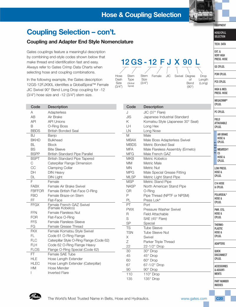
Gates couplings feature a meaningful descriptionby combining end-style codes shown below thatmake thread end identification fast and easy.Always refer to Gates Crimp Data Charts whenselecting hose and coupling combinations.
In the following example, the Gates description 12GS-12FJX90L identifies a GlobalSpiral™ FemaleJIC Swivel 90° Bend Long Drop coupling for -12(3/4") hose size and -12 (3/4") stem size.
12 GS - 12 F J X 90 L
HoseDashSize(3/4”)
StemType(GlobalSpiral)
StemSize(3/4”)
JIC Swivel Degreeof
Bend(90°)
Female DropLength(Long)
Gates CorporationC21 www.gates.com ®
®
EQUIPMENT
HOSE/CPLG.SELECTION
TECH. DATA
EXT. & VERY HIGHPRESS. HOSE
GS CPLGS.
PCM CPLGS.
PCS CPLGS.
HIGH & MED.PRESS. HOSE
MEGACRIMP®
CPLGS.
PC CPLGS.
FIELD ATTACHABLECPLGS.
AIR BRAKEHOSE &CPLGS.
MEGATECH®/C5HOSE &CPLGS.
LOW PRESS.HOSE & CPLGS.
C14 HOSE& CPLGS.
POLARSEAL®
HOSE & CPLGS.
PWR. STG.HOSE & CPLGS.
THERMO-PLASTICHOSE & CPLGS.
ADAPTERS
QUICK DISCONNECTCPLGS.
ACCESSORIES& ASSORT-MENTS
PART NUMBERINDEXES
FL
EE
T
Hose & Coupling Selection
Coupling Selection – continuedThread End Dash Sizes, Descriptions and Dimensions
Coupling Dash Size and End Style
Coupling Dash Size is a shorthand method of denoting the size of a particular end fitting. See Thread Chart on page C26.
EXAMPLE: 12MP denotes a 3/4" male pipe thread endfitting. The corresponding thread description fora 3/4" pipe thread is 3/4 -14 NPTF solid male.
EXAMPLE: 12FJX denotes a 3/4" female JIC swivel (37°seat) end fitting. The corresponding threaddescription for a 3/4" JIC thread is 1-1/16 – 12JIC 37° flare swivel female.
EXAMPLE: 12FL denotes a 3/4" SAE standard pressure(Code 61) flange fitting. This is the standardfitting description for a 3/4" SAE standardpressure flange.
Termination Drop Lengths
Bent tube couplings carry a suffix designation that specifiesthe degree of bend and the length of the drop.
For example, a 12FJX90S is a female JIC swivel with a 90degree bend. The “S” designates an SAE J516 short droplength. The short and long drops are specified in SAEJ516. Flat-face and metric couplings meet ISO-12151-1drop length specifications. Medium drops are not specifiedand can vary from manufacturer to manufacturer.
S – Short Drop
M – Medium Drop
L – Long Drop
XL – Extra Long Drop
Special, non-industry standard drop lengths aredesignated with a numerical suffix instead of theS,M,L code. For example, a 12FJX90-075 designatesa 75mm drop.
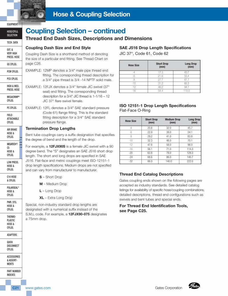
SAE J516 Drop Length SpecificationsJIC 37°, Code 61, Code 62
ISO 12151-1 Drop Length SpecificationsFlat-Face O-Ring
Thread End Catalog Descriptions
Gates coupling ends shown on the following pages areaccepted as industry standards. See detailed catalog listings for availability of specific hose/coupling combinations,detailed descriptions, thread end configurations such asswivels and bent tubes and special ends.
For Thread End Identification Tools,see Page C25.
Hose Size � Short Drop Medium Drop Long Drop(mm) (mm) (mm)
-4 20.8 32.0 45.7
-6 22.9 38.0 54.1
-8 29.2 41.0 63.8
-10 32.3 46.0 70.1
-12 47.8 58.0 96.0
-16 56.1 71.0 114.3-20 63.8 78.0 129.3
-24 68.6 86.0 140.7
-32 88.0 140.0 222.0
Hose Size Short Drop Long Drop(mm) (mm)
-4 17.3 45.7 -6 21.6 55.4 -8 27.7 61.7-10 31.2 65.3-12 46.2 94.7-16 54.4 110.0
The World’s Most Trusted Name in Belts, Hose and Hydraulics.®
®
www.gates.com C22
EQUIPMENT
HOSE/CPLG.SELECTION
TECH. DATA
EXT. & VERY HIGHPRESS. HOSE
GS CPLGS.
PCM CPLGS.
PCS CPLGS.
HIGH & MED.PRESS. HOSE
MEGACRIMP®
CPLGS.
PC CPLGS.
FIELD ATTACHABLECPLGS.
AIR BRAKEHOSE & CPLGS.
MEGATECH®/ C5HOSE & CPLGS.
LOW PRESS.HOSE & CPLGS.
C14 HOSE& CPLGS.
POLARSEAL®
HOSE & CPLGS.
PWR. STG.HOSE & CPLGS.
THERMO-PLASTICHOSE & CPLGS.
ADAPTERS
QUICK DISCONNECTCPLGS.
ACCESSORIES& ASSORT-MENTS
PART NUMBERINDEXES
FL
EE
T
Hose & Coupling Selection
Sealing Types for Hydraulic CouplingsWhen identifying hydraulic couplings, it is important to identify the type of seal made. There are three major typesof coupling interfaces used in hydraulics today: Thread Interface, O-Rings and Mated Angle or Mechanical Joint.These three interfaces have developed differently in different parts of the world. In the following pages, country oforigin and the coupling styles found in each country are identified. Brief descriptions and dimensional data helpidentify your particular coupling style.
Identifying couplings is as easy as 1-2-3!1. Determine Seal Type.
• Thread Interference• O-Ring• Mated Angle or Mechanical Joint• Mated Angle with O-Ring
Thread Interference. A characteristic of this thread is that the male is thinner at the front than it isat the back. As the male is threaded into the female, the edges of the thread distort by flattening out.This distortion creates the seal.
O-Ring. The O-Ring on the male being compressed against the corresponding female makes this seal.This type of seal is excellent for high-pressure applications. The threads pull the fitting against the port,trap the O-Ring and flatten it to form a tight seal.
Mated Angle or Mechanical Joint. Different angles are used to create the seal. The seal takes placewhere the two angles meet and are wedged into one another These can be cut with the angle either beingInverted or Standard. Standard seat couplings have the nose angle of the male on the outer surface of thecoupling. Inverted seat couplings contain the nose angle of the male on the inside bore of the coupling.
Mated Angle with O-Ring. These couplings are a hybrid, which use both the mated angle and the O-Ring to make the seal.
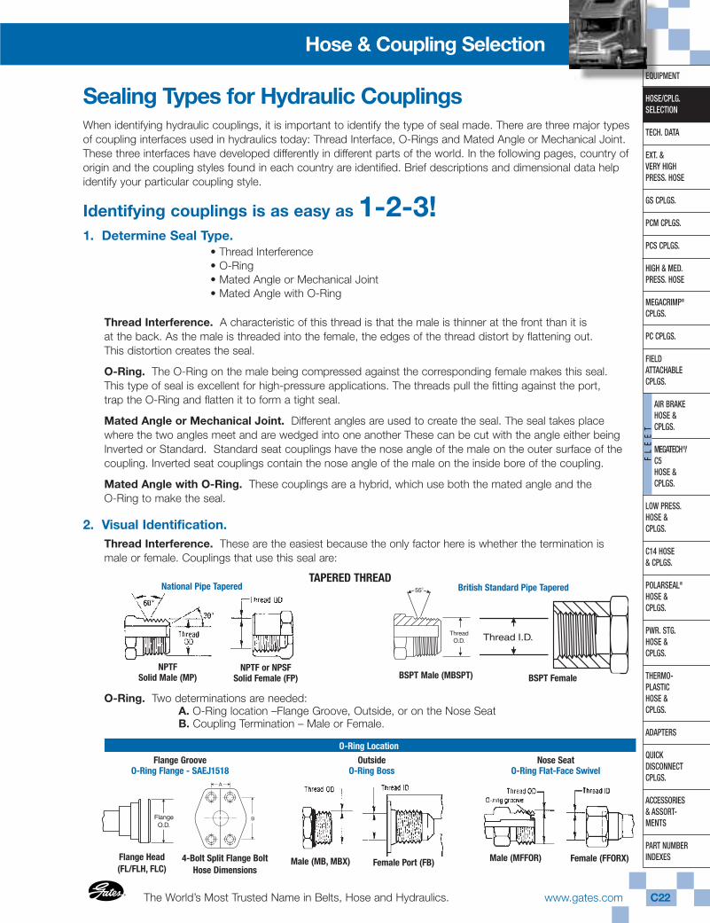
2. Visual Identification.Thread Interference. These are the easiest because the only factor here is whether the termination ismale or female. Couplings that use this seal are:
O-Ring. Two determinations are needed: A. O-Ring location –Flange Groove, Outside, or on the Nose SeatB. Coupling Termination – Male or Female.
NPTF Solid Male (MP)
NPTF or NPSFSolid Female (FP) BSPT Male (MBSPT) BSPT Female
4-Bolt Split Flange Bolt Hose Dimensions
Flange Head (FL/FLH, FLC)
Male (MB, MBX) Female Port (FB) Male (MFFOR) Female (FFORX)
National Pipe TaperedTAPERED THREAD
British Standard Pipe Tapered
O-Ring Location
Nose SeatO-Ring Flat-Face Swivel
OutsideO-Ring Boss
Flange GrooveO-Ring Flange - SAEJ1518
Gates CorporationC23 www.gates.com ®
®
EQUIPMENT
HOSE/CPLG.SELECTION
TECH. DATA
EXT. & VERY HIGHPRESS. HOSE
GS CPLGS.
PCM CPLGS.
PCS CPLGS.
HIGH & MED.PRESS. HOSE
MEGACRIMP®
CPLGS.
PC CPLGS.
FIELD ATTACHABLECPLGS.
AIR BRAKEHOSE &CPLGS.
MEGATECH®/C5HOSE &CPLGS.
LOW PRESS.HOSE & CPLGS.
C14 HOSE& CPLGS.
POLARSEAL®
HOSE & CPLGS.
PWR. STG.HOSE & CPLGS.
THERMO-PLASTICHOSE & CPLGS.
ADAPTERS
QUICK DISCONNECTCPLGS.
ACCESSORIES& ASSORT-MENTS
PART NUMBERINDEXES
FL
EE
T
Hose & Coupling Selection
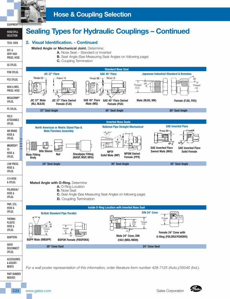
2. Visual Identification. - ContinuedMated Angle or Mechanical Joint. Determine:
A. Nose Seat – Standard or InvertedB. Seat Angle (See Measuring Seat Angles on following page)C. Coupling Termination
Mated Angle with O-Ring. Determine:A. O-Ring LocationB. Nose SeatC. Seat Angle (See Measuring Seat Angles on following page)D. Coupling Termination
For a wall poster representation of this information, order literature form number 428-7125 (Auto.)/35040 (Ind.).
JIC 37° Flare SwivelFemale (FJX)
SAE 45° FlareMale (MS)
SAE 45° Flare Swivel Female (FSX)
30o
30o
ThreadO.D.
ThreadI.D.
Swivel Female(FKX)
Solid Male(MK)
30o
30o
ThreadO.D.
ThreadI.D.
Swivel Female(FKX)
Solid Male(MK) Female (FJIS, FKX)Male (MJIS, MK)JIC 37° Male
(MJ, MJLN)
37° Seat Angle 45° Seat Angle 30° Seat Angle
Inverted Nose Seats
24° Seat Angle 30° Seat Angle 45° Seat Angle
Inside O-Ring Location with Inverted Nose Seat
30° Cone Seat 24° Cone Seat
Bite SleeveNut Standpipe Fitting
(NASP, MSP, MFA)Male Fitting
Body
NPTF Solid Male (MP) NPSM Swivel
Female (FPX)
SAE Inverted FlareSwivel Male (MIX)
SAE Inverted FlareSolid Female
BSPOR Female (FBSPORX)Male 24° Cone, DIN2353 (MDL/MDH)
Female 24° Cone with O-Ring (FDLORX/FDHORX)
JIC 37° Flare
North American or Metric Stand Pipe &Male Flareless Assembly
British Standard Pipe Parallel DIN 24° Cone
National Pipe Straight Mechanical SAE Inverted Flare
SAE 45° Flare Japanese Industrial Standard & Komatsu
BSPP Male (MBSPP)
Sealing Types for Hydraulic Couplings – Continued
Standard Nose Seat
The World’s Most Trusted Name in Belts, Hose and Hydraulics.®
®
www.gates.com C24
Hose & Coupling SelectionEQUIPMENT
HOSE/CPLG.SELECTION
TECH. DATA
EXT. & VERY HIGHPRESS. HOSE
GS CPLGS.
PCM CPLGS.
PCS CPLGS.
HIGH & MED.PRESS. HOSE
MEGACRIMP®
CPLGS.
PC CPLGS.
FIELD ATTACHABLECPLGS.
AIR BRAKEHOSE & CPLGS.
MEGATECH®/ C5HOSE & CPLGS.
LOW PRESS.HOSE & CPLGS.
C14 HOSE& CPLGS.
POLARSEAL®
HOSE & CPLGS.
PWR. STG.HOSE & CPLGS.
THERMO-PLASTICHOSE & CPLGS.
ADAPTERS
QUICK DISCONNECTCPLGS.
ACCESSORIES& ASSORT-MENTS
PART NUMBERINDEXES
FL
EE
T
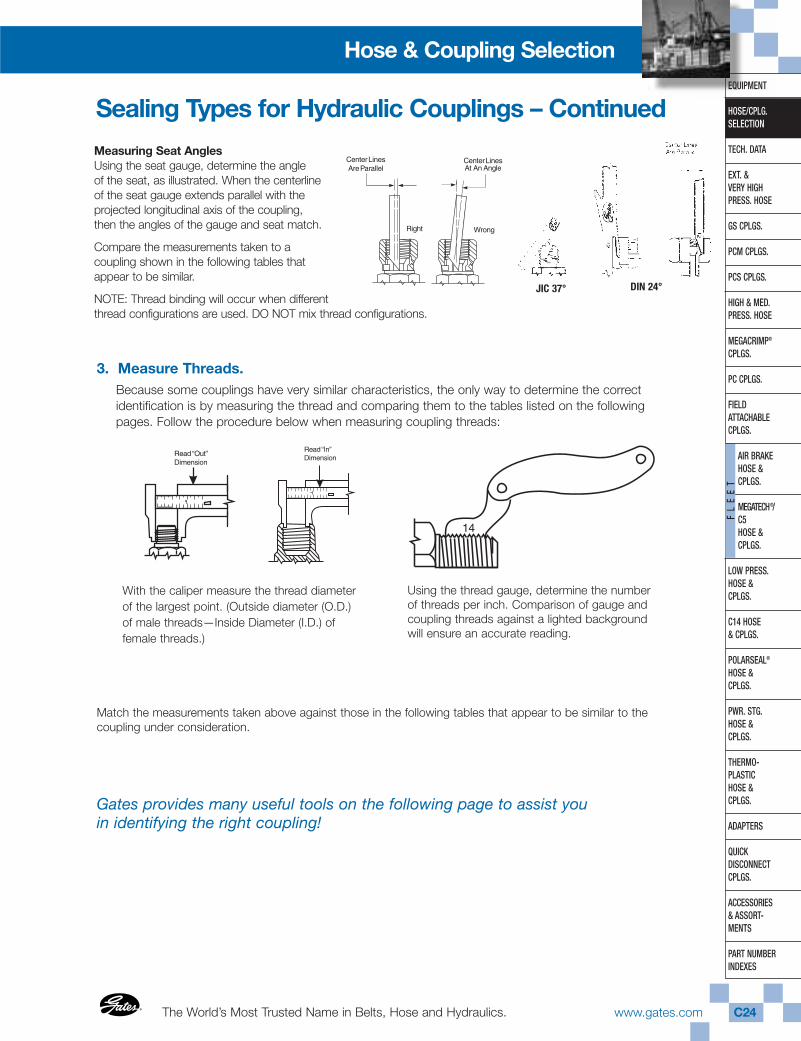
Measuring Seat AnglesUsing the seat gauge, determine the angleof the seat, as illustrated. When the centerlineof the seat gauge extends parallel with theprojected longitudinal axis of the coupling,then the angles of the gauge and seat match.
Compare the measurements taken to acoupling shown in the following tables thatappear to be similar.
NOTE: Thread binding will occur when differentthread configurations are used. DO NOT mix thread configurations.
3. Measure Threads.Because some couplings have very similar characteristics, the only way to determine the correctidentification is by measuring the thread and comparing them to the tables listed on the followingpages. Follow the procedure below when measuring coupling threads:
Match the measurements taken above against those in the following tables that appear to be similar to thecoupling under consideration.
Gates provides many useful tools on the following page to assist youin identifying the right coupling!
With the caliper measure the thread diameterof the largest point. (Outside diameter (O.D.)of male threads—Inside Diameter (I.D.) offemale threads.)
Using the thread gauge, determine the numberof threads per inch. Comparison of gauge andcoupling threads against a lighted backgroundwill ensure an accurate reading.
Sealing Types for Hydraulic Couplings – Continued
JIC 37° DIN 24°

Gates CorporationC25 www.gates.com ®
®
EQUIPMENT
HOSE/CPLG.SELECTION
TECH. DATA
EXT. & VERY HIGHPRESS. HOSE
GS CPLGS.
PCM CPLGS.
PCS CPLGS.
HIGH & MED.PRESS. HOSE
MEGACRIMP®
CPLGS.
PC CPLGS.
FIELD ATTACHABLECPLGS.
AIR BRAKEHOSE &CPLGS.
MEGATECH®/C5HOSE &CPLGS.
LOW PRESS.HOSE & CPLGS.
C14 HOSE& CPLGS.
POLARSEAL®
HOSE & CPLGS.
PWR. STG.HOSE & CPLGS.
THERMO-PLASTICHOSE & CPLGS.
ADAPTERS
QUICK DISCONNECTCPLGS.
ACCESSORIES& ASSORT-MENTS
PART NUMBERINDEXES
FL
EE
T
Hose & Coupling Selection
Pocket ThreadIdentification KitPart Number: 86583Product Number: 7369-4318
To properly identify the correct Gates replacement couplings, the measuring tools shown here should be used.
Contents: CalipersSeat Gauges (English)Seat Gauges (Metric)Thread GaugesThread I.D. Guide.
Hydraulic Coupling TemplatesAutomotive Advertising Number: 428-7108Industrial Advertising Number: 39549
These templates provide a fast and easy way to measureNorth American threads, International threads, and flangeends, seat angles (37° and 45° ) and hose I.D.
Stainless Steel Digital CaliperPart Number: 78241Product Number: 7369-1322
Caliper features an easy-to-read LCD screen clearlydisplaying the crimp diameter digitally. Capable offour-way measurement… inside, outside, depthand step. Constructed of hardened stainless steeland comes in a handy, protective carrying case.
International ThreadIdentification KitPart Number: 86580Product Number: 7369-0319
A sturdy, attractive carrying case suitable for counterdisplay and field sales calls. Contains male metric & BSPplugs for identifying thread size, pocket thread I.D. kit,and flow chart with step-by-step instructions. For femalethread identification, simply couple with the mating male.
Coupling/Thread Identification Tools
The World’s Most Trusted Name in Belts, Hose and Hydraulics.®
®
www.gates.com C26
EQUIPMENT
HOSE/CPLG.SELECTION
TECH. DATA
EXT. & VERY HIGHPRESS. HOSE
GS CPLGS.
PCM CPLGS.
PCS CPLGS.
HIGH & MED.PRESS. HOSE
MEGACRIMP®
CPLGS.
PC CPLGS.
FIELD ATTACHABLECPLGS.
AIR BRAKEHOSE & CPLGS.
MEGATECH®/ C5HOSE & CPLGS.
LOW PRESS.HOSE & CPLGS.
C14 HOSE& CPLGS.
POLARSEAL®
HOSE & CPLGS.
PWR. STG.HOSE & CPLGS.
THERMO-PLASTICHOSE & CPLGS.
ADAPTERS
QUICK DISCONNECTCPLGS.
ACCESSORIES& ASSORT-MENTS
PART NUMBERINDEXES
FL
EE
T
Hose & Coupling Selection
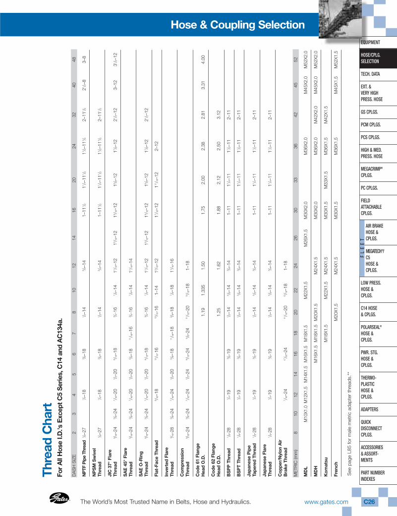
Thre
ad C
hart
For
All
Hos
e I.D
.'s E
xcep
t C5
Ser
ies,
C14
and
AC
134a
.
DA
SH
SIZ
E2
34
56
78
1012
1416
2024
3240
48
NP
TF P
ipe
Thre
ad1 /8
–27
1 /4–1
83 /8
–18
1 /2–1
43 /4
–14
1–11
1 /211 /4
–111 /2
11 /2–1
11 /22–
111 /2
21 /2–8
3–8
NP
SM
Sw
ivel
Thre
ad1 /8
–27
1 /4–1
83 /8
–18
1 /2–1
43 /4
–14
1–11
1 /211 /4
–111 /2
11 /2–1
11 /22–
111 /2
JIC
37°
Flar
eTh
read
5 /16–
243 /8
–24
7 /16–
201 /2
–20
9 /16–
183 /4
-16
7 /8–1
411 /1
6–12
13 /16–
1215 /1
6–12
15 /8–1
217 /8
–12
21 /2–1
23–
1231 /2
–12
SA
E 4
5°Fl
are
Thre
ad5 /1
6–24
3 /8–2
47 /1
6–20
1 /2–2
05 /8
–18
11/16
–16
3 /4-1
67 /8
–14
11 /16–
14
SA
E O
-Rin
gTh
read
5 /16–
243 /8
–24
7 /16–
201 /2
–20
9 /16–
183 /4
-16
7 /8–1
411 /1
6–12
13 /16–
1215 /1
6–12
15 /8–1
217 /8
–12
21 /2–1
2
Flat
-Fac
e Th
read
9 /16–
1811/16
-16
13/16
-16
1–14
13 /16–
1217 /1
6–12
111/16
–12
2–12
Inve
rted
Fla
reTh
read
5 /16-
283 /8
–24
7 /16–
241 /2
–20
5 /8–1
811/16
–18
3 /4–1
87 /8
–18
11 /16-
16
Com
pres
sion
Thre
ad5 /1
6–24
3 /8–2
47 /1
6–24
1 /2–2
49 /1
6–24
5 /8–2
411/16
–20
13/16
–18
1–18
Cod
e 61
Fla
nge
Hea
d O
.D.
1.19
1.33
51.
501.
752.
002.
382.
813.
314.
00
Cod
e 62
Fla
nge
Hea
d O
.D.
1.25
1.62
1.88
2.12
2.50
3.12
BS
PP
Thr
ead
1 /8-2
81 /4
-19
3 /8-1
91 /2
–14
5 /8–1
43 /4
–14
1–11
11 /4–1
111 /2
–11
2–11
BS
PT
Thre
ad1 /8
-28
1 /4-1
93 /8
-19
1 /2–1
45 /8
–14
3 /4–1
41–
1111 /4
–11
11 /2–1
12–
11
Japa
nese
Pip
eTa
pere
d Th
read
1 /8-2
81 /4
-19
3 /8-1
91 /2
–14
5 /8–1
43 /4
–14
1–11
11 /4–1
111 /2
–11
2–11
Japa
nese
Fla
reTh
read
1 /8-2
81 /4
-19
3 /8-1
91 /2
–14
5 /8–1
43 /4
–14
1–11
11 /4–1
111 /2
–11
2–11
Cop
per/
Nyl
on A
irB
rake
Thr
ead
7 /16–
2417/32
–24
11/16
–20
13/16
–18
1–18
MET
RIC
(mm
)8
1012
1416
1820
2224
2630
3336
4245
52
MD
LM
10X1
.0M
12X1
.5M
14X1
.5M
16X1
.5M
18X1
.5M
22X1
.5M
26X1
.5M
30X2
.0M
36X2
.0M
45X2
.0M
52X2
.0
MD
HM
16X1
.5M
18X1
.5M
20X1
.5M
24X1
.5M
30X2
.0M
36X2
.0M
42X2
.0M
45X2
.0M
52X2
.0
Kom
atsu
M18
X1.5
M22
X1.5
M24
X1.5
M30
X1.5
M33
X1.5
M36
X1.5
M42
X1.5
Fren
chM
20X1
.5M
24X1
.5M
30X1
.5M
36X1
.5M
45X1
.5M
52X1
.5
See
pag
e L8
5 fo
r m
ale
met
ric a
dapt
er t
hrea
ds.*
*
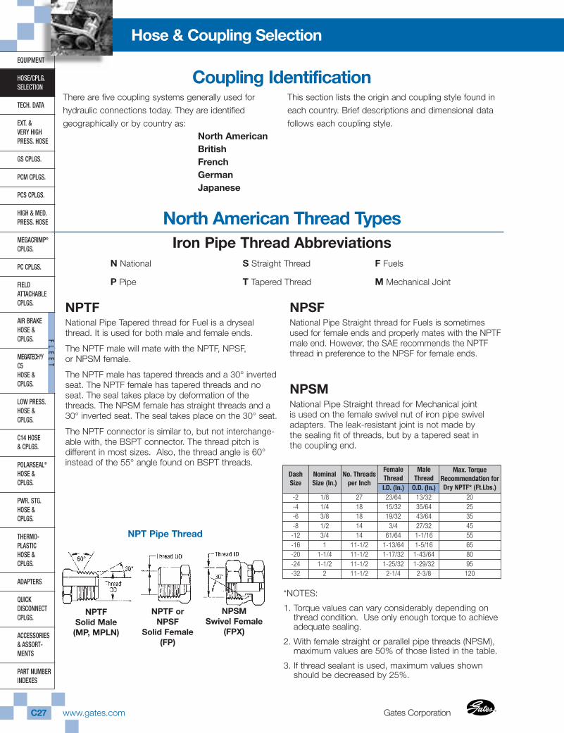
Gates CorporationC27 www.gates.com ®
®
EQUIPMENT
HOSE/CPLG.SELECTION
TECH. DATA
EXT. & VERY HIGHPRESS. HOSE
GS CPLGS.
PCM CPLGS.
PCS CPLGS.
HIGH & MED.PRESS. HOSE
MEGACRIMP®
CPLGS.
PC CPLGS.
FIELD ATTACHABLECPLGS.
AIR BRAKEHOSE &CPLGS.
MEGATECH®/C5HOSE &CPLGS.
LOW PRESS.HOSE & CPLGS.
C14 HOSE& CPLGS.
POLARSEAL®
HOSE & CPLGS.
PWR. STG.HOSE & CPLGS.
THERMO-PLASTICHOSE & CPLGS.
ADAPTERS
QUICK DISCONNECTCPLGS.
ACCESSORIES& ASSORT-MENTS
PART NUMBERINDEXES
FL
EE
T
Hose & Coupling Selection
There are five coupling systems generally used forhydraulic connections today. They are identifiedgeographically or by country as:
North AmericanBritishFrenchGermanJapanese
This section lists the origin and coupling style found ineach country. Brief descriptions and dimensional data follows each coupling style.
NPTF National Pipe Tapered thread for Fuel is a drysealthread. It is used for both male and female ends.
The NPTF male will mate with the NPTF, NPSF,or NPSM female.
The NPTF male has tapered threads and a 30° invertedseat. The NPTF female has tapered threads and noseat. The seal takes place by deformation of thethreads. The NPSM female has straight threads and a30° inverted seat. The seal takes place on the 30° seat.
The NPTF connector is similar to, but not interchange-able with, the BSPT connector. The thread pitch isdifferent in most sizes. Also, the thread angle is 60°instead of the 55° angle found on BSPT threads.
NPSFNational Pipe Straight thread for Fuels is sometimesused for female ends and properly mates with the NPTFmale end. However, the SAE recommends the NPTFthread in preference to the NPSF for female ends.
NPSM National Pipe Straight thread for Mechanical jointis used on the female swivel nut of iron pipe swiveladapters. The leak-resistant joint is not made bythe sealing fit of threads, but by a tapered seat inthe coupling end.
NPTFSolid Male(MP, MPLN)
NPTF orNPSF
Solid Female (FP)
NPSMSwivel Female
(FPX)
NPT Pipe Thread
North American Thread TypesIron Pipe Thread Abbreviations
N National
P Pipe
S Straight Thread
T Tapered Thread
F Fuels
M Mechanical Joint
Coupling Identification
DashSize
NominalSize (In.)
No. Threadsper Inch
FemaleThread
MaleThread
Max. TorqueRecommendation forDry NPTF* (Ft.Lbs.)I.D. (In.) O.D. (In.)
-2 1/8 27 23/64 13/32 20-4 1/4 18 15/32 35/64 25-6 3/8 18 19/32 43/64 35-8 1/2 14 3/4 27/32 45-12 3/4 14 61/64 1-1/16 55-16 1 11-1/2 1-13/64 1-5/16 65-20 1-1/4 11-1/2 1-17/32 1-43/64 80-24 1-1/2 11-1/2 1-25/32 1-29/32 95-32 2 11-1/2 2-1/4 2-3/8 120
*NOTES:
1. Torque values can vary considerably depending onthread condition. Use only enough torque to achieveadequate sealing.
2. With female straight or parallel pipe threads (NPSM),maximum values are 50% of those listed in the table.
3. If thread sealant is used, maximum values shownshould be decreased by 25%.
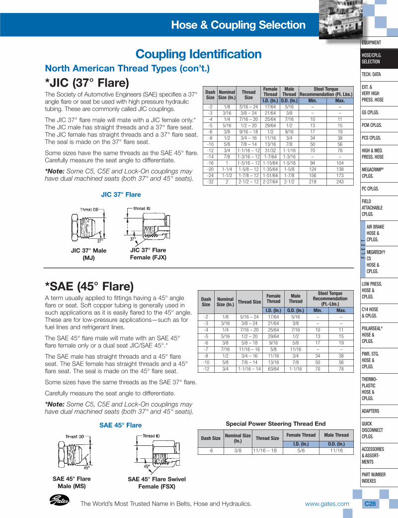
The World’s Most Trusted Name in Belts, Hose and Hydraulics.®
®
www.gates.com C28
EQUIPMENT
HOSE/CPLG.SELECTION
TECH. DATA
EXT. & VERY HIGHPRESS. HOSE
GS CPLGS.
PCM CPLGS.
PCS CPLGS.
HIGH & MED.PRESS. HOSE
MEGACRIMP®
CPLGS.
PC CPLGS.
FIELD ATTACHABLECPLGS.
AIR BRAKEHOSE & CPLGS.
MEGATECH®/ C5HOSE & CPLGS.
LOW PRESS.HOSE & CPLGS.
C14 HOSE& CPLGS.
POLARSEAL®
HOSE & CPLGS.
PWR. STG.HOSE & CPLGS.
THERMO-PLASTICHOSE & CPLGS.
ADAPTERS
QUICK DISCONNECTCPLGS.
ACCESSORIES& ASSORT-MENTS
PART NUMBERINDEXES
FL
EE
T
Hose & Coupling Selection
North American Thread Types (con’t.)
*JIC (37° Flare)The Society of Automotive Engineers (SAE) specifies a 37°angle flare or seat be used with high pressure hydraulic tubing. These are commonly called JIC couplings.
The JIC 37° flare male will mate with a JIC female only.*The JIC male has straight threads and a 37° flare seat.The JIC female has straight threads and a 37° flare seat.The seal is made on the 37° flare seat.
Some sizes have the same threads as the SAE 45° flare.Carefully measure the seat angle to differentiate.
*Note: Some C5, C5E and Lock-On couplings mayhave dual machined seats (both 37° and 45° seats).
JIC 37° Male(MJ)
JIC 37° Flare
JIC 37° FlareFemale (FJX)
*SAE (45° Flare)A term usually applied to fittings having a 45° angle flare or seat. Soft copper tubing is generally used insuch applications as it is easily flared to the 45° angle.These are for low-pressure applications—such as forfuel lines and refrigerant lines.
The SAE 45° flare male will mate with an SAE 45°flare female only or a dual seat JIC/SAE 45°.*
The SAE male has straight threads and a 45° flareseat. The SAE female has straight threads and a 45°flare seat. The seal is made on the 45° flare seat.
Some sizes have the same threads as the SAE 37° flare.
Carefully measure the seat angle to differentiate.
*Note: Some C5, C5E and Lock-On couplings mayhave dual machined seats (both 37° and 45° seats).
SAE 45° Flare Special Power Steering Thread End
SAE 45° FlareMale (MS)
SAE 45° Flare SwivelFemale (FSX)
DashSize
NominalSize (In.)
ThreadSize
FemaleThread
MaleThread
Steel TorqueRecommendation (Ft. Lbs.)
I.D. (In.) O.D. (In.) Min. Max.-2 1/8 5/16 – 24 17/64 5/16 – –-3 3/16 3/8 – 24 21/64 3/8 – –-4 1/4 7/16 – 20 25/64 7/16 10 11-5 5/16 1/2 – 20 29/64 1/2 13 15-6 3/8 9/16 – 18 1/2 9/16 17 19-8 1/2 3/4 – 16 11/16 3/4 34 38-10 5/8 7/8 – 14 13/16 7/8 50 56-12 3/4 1-1/16 – 12 31/32 1-1/16 70 78-14 7/8 1-3/16 – 12 1-7/64 1-3/16 – –-16 1 1-5/16 – 12 1-15/64 1-5/16 94 104-20 1-1/4 1-5/8 – 12 1-35/64 1-5/8 124 138-24 1-1/2 1-7/8 – 12 1-51/64 1-7/8 156 173-32 2 2-1/2 – 12 2-27/64 2-1/2 219 243
DashSize
NominalSize (In.) Thread Size
FemaleThread
MaleThread
Steel TorqueRecommendation
(Ft.-Lbs.)I.D. (In.) O.D. (In.) Min. Max.
-2 1/8 5/16 – 24 17/64 5/16 – –-3 3/16 3/8 – 24 21/64 3/8 – –-4 1/4 7/16 – 20 25/64 7/16 10 11-5 5/16 1/2 – 20 29/64 1/2 13 15-6 3/8 5/8 – 18 9/16 5/8 17 19-7 7/16 11/16 – 16 5/8 11/16 – –-8 1/2 3/4 – 16 11/16 3/4 34 38-10 5/8 7/8 – 14 13/16 7/8 50 56-12 3/4 1-1/16 – 14 63/64 1-1/16 70 78
Coupling Identification
Dash Size Nominal Size(In.) Thread Size
Female Thread Male Thread
I.D. (In.) O.D. (In.)-6 3/8 11/16 – 18 5/8 11/16
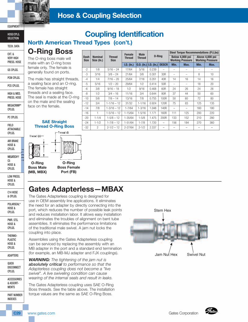
Gates CorporationC29 www.gates.com ®
®
EQUIPMENT
HOSE/CPLG.SELECTION
TECH. DATA
EXT. & VERY HIGHPRESS. HOSE
GS CPLGS.
PCM CPLGS.
PCS CPLGS.
HIGH & MED.PRESS. HOSE
MEGACRIMP®
CPLGS.
PC CPLGS.
FIELD ATTACHABLECPLGS.
AIR BRAKEHOSE &CPLGS.
MEGATECH®/C5HOSE &CPLGS.
LOW PRESS.HOSE & CPLGS.
C14 HOSE& CPLGS.
POLARSEAL®
HOSE & CPLGS.
PWR. STG.HOSE & CPLGS.
THERMO-PLASTICHOSE & CPLGS.
ADAPTERS
QUICK DISCONNECTCPLGS.
ACCESSORIES& ASSORT-MENTS
PART NUMBERINDEXES
FL
EE
T
Hose & Coupling Selection
North American Thread Types (con’t.)
O-Ring BossThe O-ring boss male willmate with an O-ring bossfemale only. The female isgenerally found on ports.
The male has straight threads,a sealing face and an O-ring.The female has straightthreads and a sealing face.The seal is made at the O-ringon the male and the sealingface on the female.
Gates Adapterless—MBAXThe Gates Adapterless coupling is designed foruse in OEM assembly line applications. It eliminatesthe need for an adapter by directly connecting into theport, which reduces the number of possible leak pointsand reduces installation labor. It allows easy installationand eliminates the troubles of alignment on bent tubeassemblies. It eliminates the performance limitationsof the traditional male swivel. A jam nut locks thecoupling into place.
Assemblies using the Gates Adapterless couplingcan be serviced by replacing the assembly with anMB adapter in the port and a standard end termination(for example, an MB-MJ adapter and FJX couplings).
WARNING: The tightening of the jam nut isabsolutely critical to performance so that theAdapterless coupling does not become a "liveswivel". A live swiveling condition can causewearing of the internal seals and result in leaks.
The Gates Adapterless coupling uses SAE O-RingBoss threads. See the table above. The installationtorque values are the same as SAE O-Ring Boss.
DashSize
NominalSize (In.)
ThreadSize
FemaleThread
MaleThread O-Ring
Steel Torque Recommendations (Ft.Lbs)Below 4,000 psi
Working PressureAbove 4,000 psi
Working PressureI.D. (In.) O.D. (In.) I.D. (In.) DESCR Min. Max. Min. Max.
-2 1/8 5/16 – 24 17/64 5/16 0.239 – – – – –
-3 3/16 3/8 – 24 21/64 3/8 0.301 30R – – 8 10
-4 1/4 7/16 – 20 25/64 7/16 0.351 40R 14 16 14 16
-5 5/16 1/2 – 20 29/64 1/2 0.414 50R – – 18 20
-6 3/8 9/16 – 18 1/2 9/16 0.468 60R 24 26 24 26
-8 1/2 3/4 – 16 11/16 3/4 0.644 80R 37 44 50 60
-10 5/8 7/8 – 14 13/16 7/8 0.755 100R 50 60 72 80
-12 3/4 1-1/16 – 12 31/32 1-1/16 0.924 120R 75 83 125 135
-14 7/8 1-3/16 – 12 1-7/64 1-3/16 1.048 140R – – 160 180
-16 1 1-5/16 – 12 1-15/64 1-5/16 1.171 160R 111 125 200 220
-20 1-1/4 1-5/8 – 12 1-35/64 1-5/8 1.475 200R 133 152 210 280
-24 1-1/2 1-7/8 – 12 1-51/64 1-7/8 1.720 – 156 184 270 360
-32 2 2-1/2 – 12 2-27/64 2-1/2 2.337 – – – – –
SAE StraightThread O-Ring Boss
O-RingBoss Male(MB, MBX)
O-Ring Boss Female
Port (FB)
Stem Hex
Swivel NutJam Nut Hex
Coupling Identification
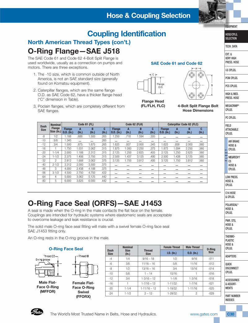
The World’s Most Trusted Name in Belts, Hose and Hydraulics.®
®
www.gates.com C30
EQUIPMENT
HOSE/CPLG.SELECTION
TECH. DATA
EXT. & VERY HIGHPRESS. HOSE
GS CPLGS.
PCM CPLGS.
PCS CPLGS.
HIGH & MED.PRESS. HOSE
MEGACRIMP®
CPLGS.
PC CPLGS.
FIELD ATTACHABLECPLGS.
AIR BRAKEHOSE & CPLGS.
MEGATECH®/ C5HOSE & CPLGS.
LOW PRESS.HOSE & CPLGS.
C14 HOSE& CPLGS.
POLARSEAL®
HOSE & CPLGS.
PWR. STG.HOSE & CPLGS.
THERMO-PLASTICHOSE & CPLGS.
ADAPTERS
QUICK DISCONNECTCPLGS.
ACCESSORIES& ASSORT-MENTS
PART NUMBERINDEXES
FL
EE
T
Hose & Coupling Selection
North American Thread Types (con’t.)
4-Bolt Split Flange BoltHose Dimensions
SAE Code 61 and Code 62
Flange Head(FL/FLH, FLC)
O-Ring Face Seal (ORFS)—SAE J1453A seal is made when the O-ring in the male contacts the flat face on the female.Couplings are intended for hydraulic systems where elastomeric seals are acceptableto overcome leakage and leak resistance is crucial.
The solid male O-ring face seal fitting will mate with a swivel female O-ring face sealSAE J1453 fitting only.
An O-ring rests in the O-ring groove in the male.
Male Flat-Face O-Ring
(MFFOR)
O-Ring Face Seal
Female Flat-Face O-Ring
Swivel(FFORX)
Coupling Identification
O-Ring Flange—SAE J518The SAE Code 61 and Code 62 4-Bolt Split Flange isused worldwide, usually as a connection on pumps andmotors. There are three exceptions.
1. The -10 size, which is common outside of NorthAmerica, is not an SAE standard size (generallyfound on Komatsu equipment).
2. Caterpillar flanges, which are the same flangeO.D. as SAE Code 62, have a thicker flange head (“C” dimension in Table).
3. Poclain flanges, which are completely different fromSAE flanges.
DashSize
NominalFlange
Size (In.)
Code 61 (FL) Code 62 (FLH) Caterpillar Code 62 (FLC)
Flange A B CO.D. (In.) (In.) (In.) (In.)
Flange A B CO.D. (In.) (In.) (In.) (In.)
Flange A B CO.D. (In.) (In.) (In.) (In.)
-8 1/2 1.188 .688 1.500 .265 1.250 .718 1.594 .305 – – – –-10 5/8 1.345 – – .265 – – – – – – – –-12 3/4 1.500 .875 1.875 .265 1.625 .937 2.000 .345 1.625 .938 2.000 .560-16 1 1.750 1.031 2.062 .315 1.875 1.093 2.250 .375 1.875 1.094 2.250 .560-20 1-1/4 2.000 1.188 2.312 .315 2.125 1.250 2.625 .405 2.125 1.250 2.625 .560-24 1-1/2 2.375 1.406 2.750 .315 2.500 1.437 3.125 .495 2.500 1.438 3.125 .560-32 2 2.812 1.688 3.062 .375 3.125 1.750 3.812 .495 3.125 1.750 3.812 .560-40 2-1/2 3.312 2.000 3.500 .375 – – – – – – – –-48 3 4.000 2.438 4.188 .375 – – – – – – – –-56 3-1/2 4.500 2.750 4.750 .422 – – – – – – – –-64 4 5.000 3.062 5.125 .442 – – – – – – – –-80 5 6.000 3.625 6.000 .442 – – – – – – – –
Nominal Female Thread Male ThreadDash Size Thread O-RingSize (In.) Size I.D. (In.) O.D. (In.) Size
-4 1/4 9/16 – 18 1/2 9/16 -011
-6 3/8 11/16 – 16 5/8 11/16 -012
-8 1/2 13/16 – 16 3/4 13/16 -014
-10 5/8 1 – 14 15/16 1 -016
-12 3/4 1-3/16 – 12 1-1/8 1-3/16 -018
-16 1 1-7/16 – 12 1-11/32 1-7/16 -021
-20 1-1/4 1-11/16 – 12 1-19/32 1-11/16 -025
-24 1-1/2 2 – 12 1-29/32 2 -029
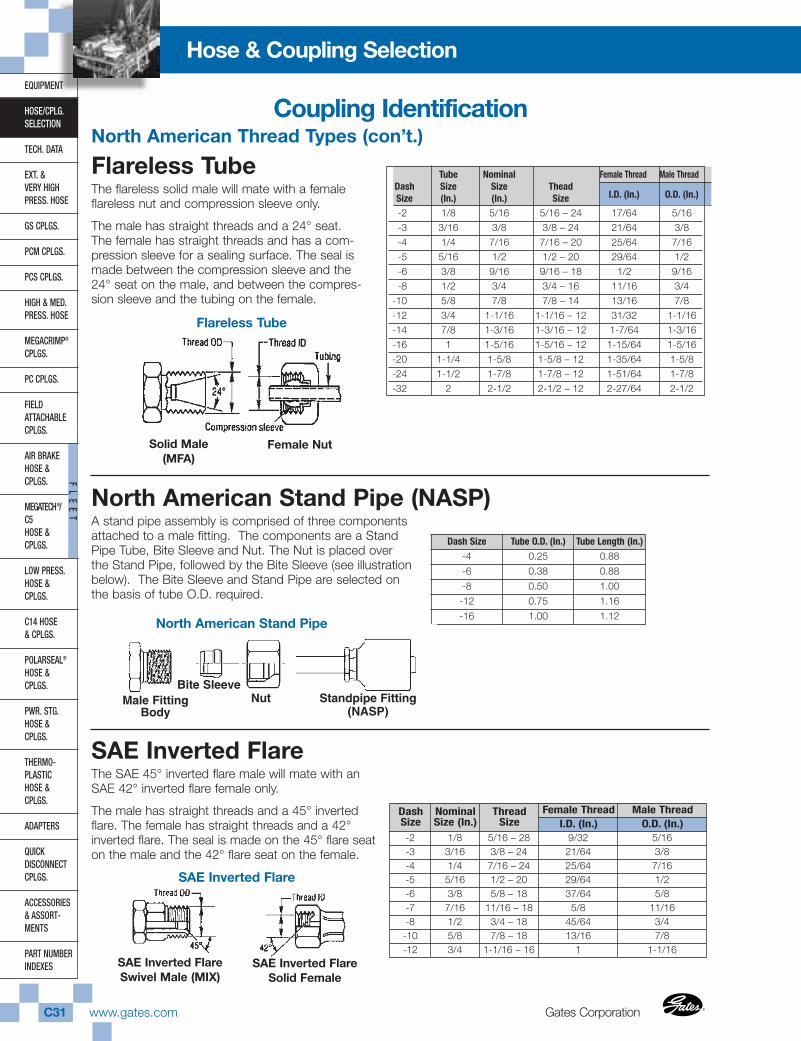
Gates CorporationC31 www.gates.com ®
®
EQUIPMENT
HOSE/CPLG.SELECTION
TECH. DATA
EXT. & VERY HIGHPRESS. HOSE
GS CPLGS.
PCM CPLGS.
PCS CPLGS.
HIGH & MED.PRESS. HOSE
MEGACRIMP®
CPLGS.
PC CPLGS.
FIELD ATTACHABLECPLGS.
AIR BRAKEHOSE &CPLGS.
MEGATECH®/C5HOSE &CPLGS.
LOW PRESS.HOSE & CPLGS.
C14 HOSE& CPLGS.
POLARSEAL®
HOSE & CPLGS.
PWR. STG.HOSE & CPLGS.
THERMO-PLASTICHOSE & CPLGS.
ADAPTERS
QUICK DISCONNECTCPLGS.
ACCESSORIES& ASSORT-MENTS
PART NUMBERINDEXES
FL
EE
T
Hose & Coupling Selection
Flareless TubeThe flareless solid male will mate with a femaleflareless nut and compression sleeve only.
The male has straight threads and a 24° seat.The female has straight threads and has a com-pression sleeve for a sealing surface. The seal ismade between the compression sleeve and the24° seat on the male, and between the compres-sion sleeve and the tubing on the female.
Solid Male(MFA)
Flareless Tube
Female Nut
SAE Inverted FlareThe SAE 45° inverted flare male will mate with anSAE 42° inverted flare female only.
The male has straight threads and a 45° invertedflare. The female has straight threads and a 42°inverted flare. The seal is made on the 45° flare seaton the male and the 42° flare seat on the female.
SAE Inverted FlareSwivel Male (MIX)
SAE Inverted Flare
SAE Inverted FlareSolid Female
North American Stand Pipe (NASP)A stand pipe assembly is comprised of three components attached to a male fitting. The components are a Stand Pipe Tube, Bite Sleeve and Nut. The Nut is placed over the Stand Pipe, followed by the Bite Sleeve (see illustration below). The Bite Sleeve and Stand Pipe are selected on the basis of tube O.D. required.
Coupling IdentificationNorth American Thread Types (con’t.)
Tube Nominal Female Thread Male ThreadDash Size Size TheadSize (In.) (In.) Size I.D. (In.) O.D. (In.)
-2 1/8 5/16 5/16 – 24 17/64 5/16-3 3/16 3/8 3/8 – 24 21/64 3/8-4 1/4 7/16 7/16 – 20 25/64 7/16-5 5/16 1/2 1/2 – 20 29/64 1/2-6 3/8 9/16 9/16 – 18 1/2 9/16-8 1/2 3/4 3/4 – 16 11/16 3/4
-10 5/8 7/8 7/8 – 14 13/16 7/8-12 3/4 1-1/16 1-1/16 – 12 31/32 1-1/16-14 7/8 1-3/16 1-3/16 – 12 1-7/64 1-3/16-16 1 1-5/16 1-5/16 – 12 1-15/64 1-5/16-20 1-1/4 1-5/8 1-5/8 – 12 1-35/64 1-5/8-24 1-1/2 1-7/8 1-7/8 – 12 1-51/64 1-7/8-32 2 2-1/2 2-1/2 – 12 2-27/64 2-1/2
Dash Size Tube O.D. (In.) Tube Length (In.)
-4 0.25 0.88
-6 0.38 0.88
-8 0.50 1.00
-12 0.75 1.16
-16 1.00 1.12
DashSize
NominalSize (In.)
ThreadSize
Female Thread Male ThreadI.D. (In.) O.D. (In.)
-2 1/8 5/16 – 28 9/32 5/16-3 3/16 3/8 – 24 21/64 3/8-4 1/4 7/16 – 24 25/64 7/16-5 5/16 1/2 – 20 29/64 1/2-6 3/8 5/8 – 18 37/64 5/8-7 7/16 11/16 – 18 5/8 11/16-8 1/2 3/4 – 18 45/64 3/4-10 5/8 7/8 – 18 13/16 7/8-12 3/4 1-1/16 – 16 1 1-1/16
Bite SleeveNut Standpipe Fitting
(NASP)Male Fitting
Body
North American Stand Pipe
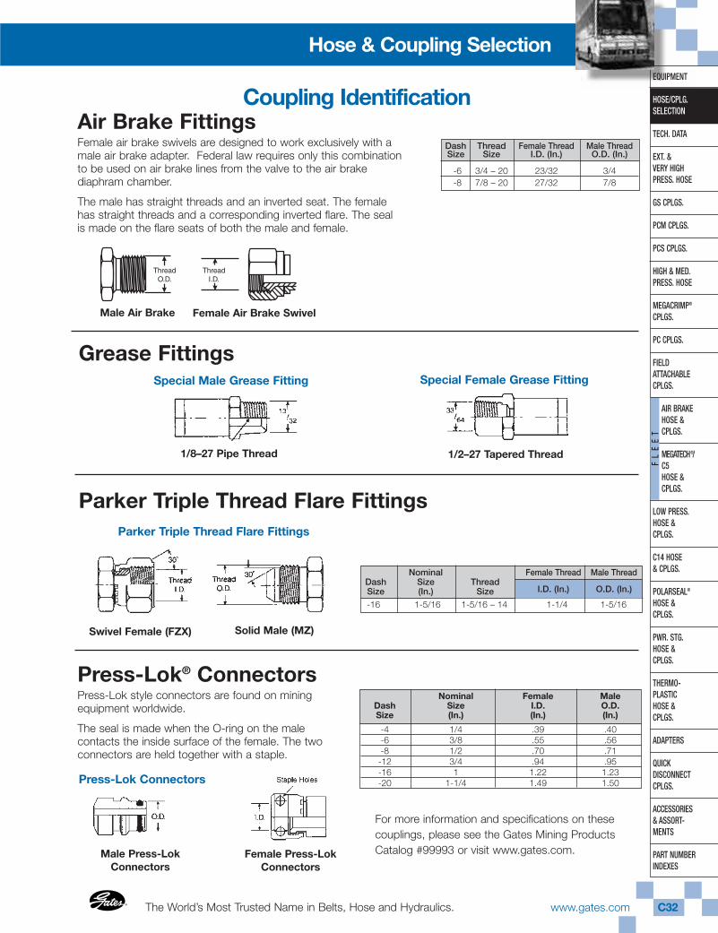
The World’s Most Trusted Name in Belts, Hose and Hydraulics.®
®
www.gates.com C32
EQUIPMENT
HOSE/CPLG.SELECTION
TECH. DATA
EXT. & VERY HIGHPRESS. HOSE
GS CPLGS.
PCM CPLGS.
PCS CPLGS.
HIGH & MED.PRESS. HOSE
MEGACRIMP®
CPLGS.
PC CPLGS.
FIELD ATTACHABLECPLGS.
AIR BRAKEHOSE & CPLGS.
MEGATECH®/ C5HOSE & CPLGS.
LOW PRESS.HOSE & CPLGS.
C14 HOSE& CPLGS.
POLARSEAL®
HOSE & CPLGS.
PWR. STG.HOSE & CPLGS.
THERMO-PLASTICHOSE & CPLGS.
ADAPTERS
QUICK DISCONNECTCPLGS.
ACCESSORIES& ASSORT-MENTS
PART NUMBERINDEXES
FL
EE
T
Hose & Coupling Selection
Grease FittingsSpecial Male Grease Fitting Special Female Grease Fitting
Parker Triple Thread Flare FittingsParker Triple Thread Flare Fittings
Swivel Female (FZX) Solid Male (MZ)
Press-Lok® ConnectorsPress-Lok style connectors are found on mining equipment worldwide.
The seal is made when the O-ring on the male contacts the inside surface of the female. The two connectors are held together with a staple.
Nominal Female MaleDash Size I.D. O.D.Size (In.) (In.) (In.)
-4 1/4 .39 .40-6 3/8 .55 .56-8 1/2 .70 .71-12 3/4 .94 .95-16 1 1.22 1.23-20 1-1/4 1.49 1.50
For more information and specifications on these couplings, please see the Gates Mining Products Catalog #99993 or visit www.gates.com.
Nominal Female Thread Male ThreadDash Size ThreadSize (In.) Size I.D. (In.) O.D. (In.)
-16 1-5/16 1-5/16 – 14 1-1/4 1-5/16
Male Press-LokConnectors
Female Press-LokConnectors
Press-Lok Connectors
Air Brake FittingsFemale air brake swivels are designed to work exclusively with amale air brake adapter. Federal law requires only this combination to be used on air brake lines from the valve to the air brake diaphram chamber.
The male has straight threads and an inverted seat. The femalehas straight threads and a corresponding inverted flare. The sealis made on the flare seats of both the male and female.
Dash Thread Female Thread Male ThreadSize Size I.D. (In.) O.D. (In.)
-6 3/4 – 20 23/32 3/4-8 7/8 – 20 27/32 7/8
1/2–27 Tapered Thread1/8–27 Pipe Thread
Male Air Brake Female Air Brake Swivel
Coupling Identification
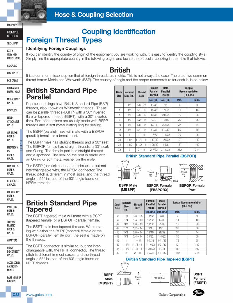
Gates CorporationC33 www.gates.com ®
®
EQUIPMENT
HOSE/CPLG.SELECTION
TECH. DATA
EXT. & VERY HIGHPRESS. HOSE
GS CPLGS.
PCM CPLGS.
PCS CPLGS.
HIGH & MED.PRESS. HOSE
MEGACRIMP®
CPLGS.
PC CPLGS.
FIELD ATTACHABLECPLGS.
AIR BRAKEHOSE &CPLGS.
MEGATECH®/C5HOSE &CPLGS.
LOW PRESS.HOSE & CPLGS.
C14 HOSE& CPLGS.
POLARSEAL®
HOSE & CPLGS.
PWR. STG.HOSE & CPLGS.
THERMO-PLASTICHOSE & CPLGS.
ADAPTERS
QUICK DISCONNECTCPLGS.
ACCESSORIES& ASSORT-MENTS
PART NUMBERINDEXES
FL
EE
T
Hose & Coupling Selection
Foreign Thread TypesIdentifying Foreign CouplingsIf you can identify the country of origin of the equipment you are working with, it is easy to identify the coupling style.Simply find the appropriate country in the following pages and locate the particular coupling in the table that follows.
BritishIt is a common misconception that all foreign threads are metric. This is not always the case. There are two commonthread forms: Metric and Whitworth (BSP). The country of origin and the proper nomenclature for each is listed below.
British Standard PipeParallelPopular couplings have British Standard Pipe (BSP)threads, also known as Whitworth threads. Thesecan be parallel threads (BSPP) with a 30° invertedflare or tapered threads (BSPT), with a 30° invertedflare. Port connections are usually made with BSPPthreads and a soft metal cutting ring for sealing.
The BSPP (parallel) male will mate with a BSPOR(parallel) female or a female port.
The BSPP male has straight threads and a 30° seat.The BSPOR female has straight threads, a 30° seat,and O-ring. The female port has straight threadsand a spotface. The seal on the port is made withan O-ring or soft metal washer on the male.
The BSPP (parallel) connector is similar to, but notinterchangeable with, the NPSM connector. Thethread pitch is different in most sizes, and the threadangle is 55° instead of the 60° angle found onNPSM threads.
BSPP Male(MBSPP)
BSPOR Female(FBSPORX)
BSPOR FemalePort
British Standard PipeTaperedThe BSPT (tapered) male will mate with a BSPT(tapered) female, or a BSPOR (parallel) female.
The BSPT male has tapered threads. When mat-ing with either the BSPT (tapered) female or theBSPOR (parallel) female port, the seal is made onthe threads.
The BSPT connector is similar to, but not inter-changeable with, the NPTF connector. The threadpitch is different in most cases, and the threadangle is 55° instead of the 60° angle found onNPTF threads.
BSPTMale
(MBSPT)
BSPTFemale(FBSPT)
Coupling Identification
DashSize
NominalSize (In.)
ThreadSize
FemaleParallelThread
MaleParallelThread
TorqueRecommendation
(Ft. Lbs.)
I.D. (In.) O.D. (In.) Min. Max.
-2 1/8 1/8 – 28 11/32 3/8 7 9
-4 1/4 1/4 – 19 15/32 17/32 11 18
-6 3/8 3/8 – 19 19/32 21/32 19 28
-8 1/2 1/2 – 14 3/4 13/16 30 36
-10 5/8 5/8 – 14 13/16 29/32 37 44
-12 3/4 3/4 – 14 31/32 1-1/32 50 60
-16 1 1 – 11 1-7/32 1-11/32 79 95
-20 1-1/4 1-1/4 – 11 1-17/32 1-21/32 127 152
-24 1-1/2 1-1/2 – 11 1-25/32 1-7/8 167 190
-32 2 2 – 11 2-7/32 2-11/32 262 314
DashSize
NominalSize(In.)
ThreadSize
FemaleParallelThread
MaleParallelThread
Torque Recommendation (Ft. Lbs.)
I.D. (In.) O.D. (In.) Min. Max.-2 1/8 1/8 – 28 11/32 3/8 7 9
-4 1/4 1/4 – 19 15/32 17/32 11 18
-6 3/8 3/8 – 19 19/32 21/32 19 28
-8 1/2 1/2 – 14 3/4 13/16 30 36
-10 5/8 5/8 – 14 13/16 29/32 37 44
-12 3/4 3/4 – 14 31/32 1-1/32 50 60
-16 1 1 – 11 1-7/32 1-11/32 79 95
-20 1-1/4 1-1/4 – 11 1-17/32 1-21/32 127 152
-24 1-1/2 1-1/2 – 11 1-25/32 1-7/8 167 190
-32 2 2 – 11 2-7/32 2-11/32 262 314
British Standard Pipe Tapered (BSPT)
British Standard Pipe Parallel (BSPOR)
O-Ring
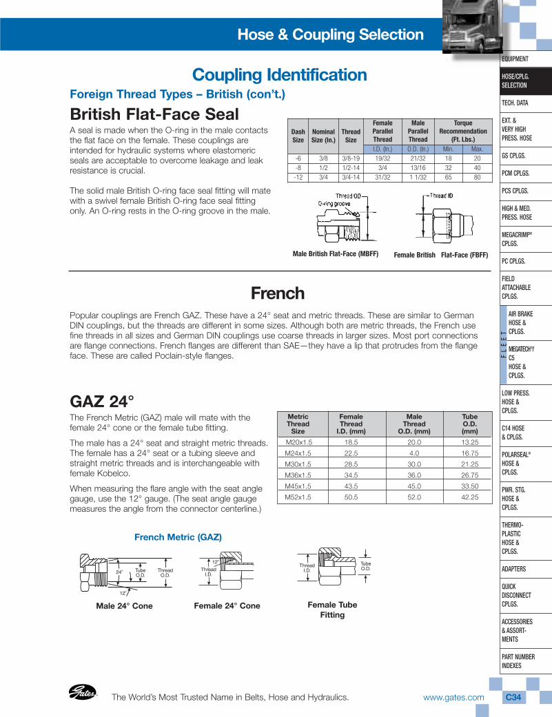
The World’s Most Trusted Name in Belts, Hose and Hydraulics.®
®
www.gates.com C34
EQUIPMENT
HOSE/CPLG.SELECTION
TECH. DATA
EXT. & VERY HIGHPRESS. HOSE
GS CPLGS.
PCM CPLGS.
PCS CPLGS.
HIGH & MED.PRESS. HOSE
MEGACRIMP®
CPLGS.
PC CPLGS.
FIELD ATTACHABLECPLGS.
AIR BRAKEHOSE & CPLGS.
MEGATECH®/ C5HOSE & CPLGS.
LOW PRESS.HOSE & CPLGS.
C14 HOSE& CPLGS.
POLARSEAL®
HOSE & CPLGS.
PWR. STG.HOSE & CPLGS.
THERMO-PLASTICHOSE & CPLGS.
ADAPTERS
QUICK DISCONNECTCPLGS.
ACCESSORIES& ASSORT-MENTS
PART NUMBERINDEXES
FL
EE
T
Hose & Coupling Selection
Foreign Thread Types – British (con’t.)
British Flat-Face SealA seal is made when the O-ring in the male contactsthe flat face on the female. These couplings areintended for hydraulic systems where elastomericseals are acceptable to overcome leakage and leakresistance is crucial.
The solid male British O-ring face seal fitting will matewith a swivel female British O-ring face seal fittingonly. An O-ring rests in the O-ring groove in the male.
FrenchPopular couplings are French GAZ. These have a 24° seat and metric threads. These are similar to GermanDIN couplings, but the threads are different in some sizes. Although both are metric threads, the French usefine threads in all sizes and German DIN couplings use coarse threads in larger sizes. Most port connectionsare flange connections. French flanges are different than SAE—they have a lip that protrudes from the flangeface. These are called Poclain-style flanges.
GAZ 24°The French Metric (GAZ) male will mate with the female 24° cone or the female tube fitting.
The male has a 24° seat and straight metric threads.The female has a 24° seat or a tubing sleeve andstraight metric threads and is interchangeable withfemale Kobelco.
When measuring the flare angle with the seat anglegauge, use the 12° gauge. (The seat angle gaugemeasures the angle from the connector centerline.)
Metric Female Male TubeThread Thread Thread O.D.
Size I.D. (mm) O.D. (mm) (mm)
M20x1.5 18.5 20.0 13.25
M24x1.5 22.5 4.0 16.75
M30x1.5 28.5 30.0 21.25
M36x1.5 34.5 36.0 26.75
M45x1.5 43.5 45.0 33.50
M52x1.5 50.5 52.0 42.25
French Metric (GAZ)
Female 24° Cone Female TubeFitting
Coupling Identification
Male 24° Cone
DashSize
NominalSize (In.)
ThreadSize
FemaleParallelThread
MaleParallelThread
TorqueRecommendation
(Ft. Lbs.)I.D. (In.) O.D. (In.) Min. Max.
-6 3/8 3/8-19 19/32 21/32 18 20-8 1/2 1/2-14 3/4 13/16 32 40-12 3/4 3/4-14 31/32 1 1/32 65 80
Male British Flat-Face (MBFF) Female British Flat-Face (FBFF)
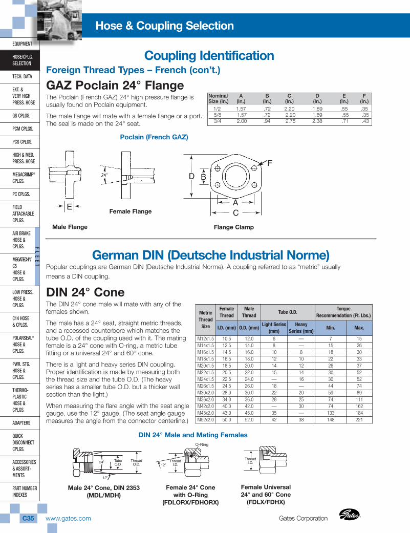
Gates CorporationC35 www.gates.com ®
®
EQUIPMENT
HOSE/CPLG.SELECTION
TECH. DATA
EXT. & VERY HIGHPRESS. HOSE
GS CPLGS.
PCM CPLGS.
PCS CPLGS.
HIGH & MED.PRESS. HOSE
MEGACRIMP®
CPLGS.
PC CPLGS.
FIELD ATTACHABLECPLGS.
AIR BRAKEHOSE &CPLGS.
MEGATECH®/C5HOSE &CPLGS.
LOW PRESS.HOSE & CPLGS.
C14 HOSE& CPLGS.
POLARSEAL®
HOSE & CPLGS.
PWR. STG.HOSE & CPLGS.
THERMO-PLASTICHOSE & CPLGS.
ADAPTERS
QUICK DISCONNECTCPLGS.
ACCESSORIES& ASSORT-MENTS
PART NUMBERINDEXES
FL
EE
T
Hose & Coupling Selection
Foreign Thread Types – French (con’t.)
GAZ Poclain 24° FlangeThe Poclain (French GAZ) 24° high pressure flange isusually found on Poclain equipment.
The male flange will mate with a female flange or a port.The seal is made on the 24° seat.
Nominal A B C D E FSize (In.) (In.) (In.) (In.) (In.) (In.) (In.)
1/2 1.57 .72 2.20 1.89 .55 .355/8 1.57 .72 2.20 1.89 .55 .353/4 2.00 .94 2.75 2.38 .71 .43
Male Flange
➛
➛
E
D B
AC
➛
➛
E
D B
AC
Poclain (French GAZ)
Female Flange
Flange Clamp
German DIN (Deutsche Industrial Norme)Popular couplings are German DIN (Deutsche Industrial Norme). A coupling referred to as “metric” usuallymeans a DIN coupling.
DIN 24° ConeThe DIN 24° cone male will mate with any of thefemales shown.
The male has a 24° seat, straight metric threads,and a recessed counterbore which matches thetube O.D. of the coupling used with it. The matingfemale is a 24° cone with O-ring, a metric tubefitting or a universal 24° and 60° cone.
There is a light and heavy series DIN coupling.Proper identification is made by measuring boththe thread size and the tube O.D. (The heavyseries has a smaller tube O.D. but a thicker wallsection than the light.)
When measuring the flare angle with the seat anglegauge, use the 12° gauge. (The seat angle gaugemeasures the angle from the connector centerline.)
O-Ring
Male 24° Cone, DIN 2353(MDL/MDH)
Female Universal24° and 60° Cone
(FDLX/FDHX)
F
Coupling Identification
MetricThread
Size
FemaleThread
MaleThread
Tube O.D.Torque
Recommendation (Ft. Lbs.)
I.D. (mm) O.D. (mm)Light Series
(mm)Heavy
Series (mm)Min. Max.
M12x1.5 10.5 12.0 6 — 7 15M14x1.5 12.5 14.0 8 — 15 26M16x1.5 14.5 16.0 10 8 18 30M18x1.5 16.5 18.0 12 10 22 33M20x1.5 18.5 20.0 14 12 26 37M22x1.5 20.5 22.0 15 14 30 52M24x1.5 22.5 24.0 — 16 30 52M26x1.5 24.5 26.0 18 — 44 74M30x2.0 28.0 30.0 22 20 59 89M36x2.0 34.0 36.0 28 25 74 111M42x2.0 40.0 42.0 — 30 74 162M45x2.0 43.0 45.0 35 — 133 184M52x2.0 50.0 52.0 42 38 148 221
Female 24° Conewith O-Ring
(FDLORX/FDHORX)
DIN 24° Male and Mating Females
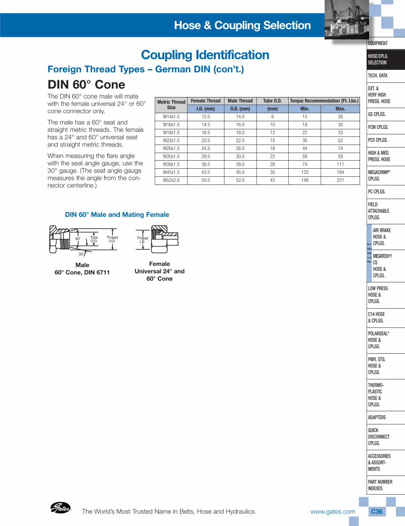
The World’s Most Trusted Name in Belts, Hose and Hydraulics.®
®
www.gates.com C36
EQUIPMENT
HOSE/CPLG.SELECTION
TECH. DATA
EXT. & VERY HIGHPRESS. HOSE
GS CPLGS.
PCM CPLGS.
PCS CPLGS.
HIGH & MED.PRESS. HOSE
MEGACRIMP®
CPLGS.
PC CPLGS.
FIELD ATTACHABLECPLGS.
AIR BRAKEHOSE & CPLGS.
MEGATECH®/ C5HOSE & CPLGS.
LOW PRESS.HOSE & CPLGS.
C14 HOSE& CPLGS.
POLARSEAL®
HOSE & CPLGS.
PWR. STG.HOSE & CPLGS.
THERMO-PLASTICHOSE & CPLGS.
ADAPTERS
QUICK DISCONNECTCPLGS.
ACCESSORIES& ASSORT-MENTS
PART NUMBERINDEXES
FL
EE
T
Hose & Coupling Selection
Foreign Thread Types – German DIN (con’t.)
DIN 60° ConeThe DIN 60° cone male will matewith the female universal 24° or 60°cone connector only.
The male has a 60° seat andstraight metric threads. The femalehas a 24° and 60° universal seatand straight metric threads.
When measuring the flare anglewith the seat angle gauge, use the30° gauge. (The seat angle gaugemeasures the angle from the con-nector centerline.)
DIN 60° Male and Mating Female
Male 60° Cone, DIN 6711
Female Universal 24° and
60° Cone
Coupling Identification
Metric ThreadSize
Female Thread Male Thread Tube O.D. Torque Recommendation (Ft. Lbs.)
I.D. (mm) O.D. (mm) (mm) Min. Max.
M14x1.5 12.5 14.0 8 15 26
M16x1.5 14.5 16.0 10 18 30
M18x1.5 16.5 18.0 12 22 33
M22x1.5 20.5 22.0 15 30 52
M26x1.5 24.5 26.0 18 44 74
M30x1.5 28.5 30.0 22 59 59
M38x1.5 36.5 38.0 28 74 111
M45x1.5 43.5 45.0 35 133 184
M52x2.0 50.5 52.0 42 148 221
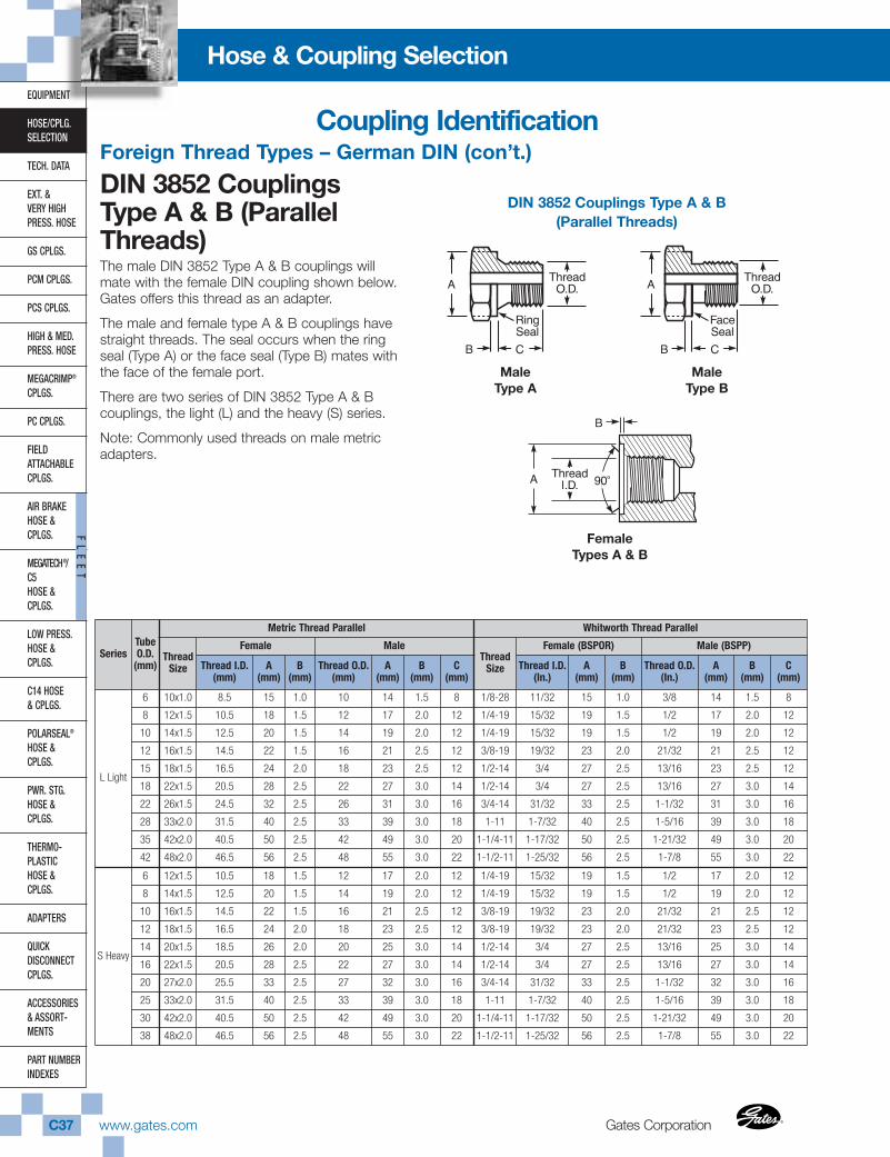
Gates CorporationC37 www.gates.com ®
®
EQUIPMENT
HOSE/CPLG.SELECTION
TECH. DATA
EXT. & VERY HIGHPRESS. HOSE
GS CPLGS.
PCM CPLGS.
PCS CPLGS.
HIGH & MED.PRESS. HOSE
MEGACRIMP®
CPLGS.
PC CPLGS.
FIELD ATTACHABLECPLGS.
AIR BRAKEHOSE &CPLGS.
MEGATECH®/C5HOSE &CPLGS.
LOW PRESS.HOSE & CPLGS.
C14 HOSE& CPLGS.
POLARSEAL®
HOSE & CPLGS.
PWR. STG.HOSE & CPLGS.
THERMO-PLASTICHOSE & CPLGS.
ADAPTERS
QUICK DISCONNECTCPLGS.
ACCESSORIES& ASSORT-MENTS
PART NUMBERINDEXES
FL
EE
T
Hose & Coupling Selection
Foreign Thread Types – German DIN (con’t.)
DIN 3852 Couplings Type A & B (ParallelThreads)The male DIN 3852 Type A & B couplings willmate with the female DIN coupling shown below.Gates offers this thread as an adapter.
The male and female type A & B couplings havestraight threads. The seal occurs when the ringseal (Type A) or the face seal (Type B) mates withthe face of the female port.
There are two series of DIN 3852 Type A & Bcouplings, the light (L) and the heavy (S) series.
Note: Commonly used threads on male metricadapters.
DIN 3852 Couplings Type A & B(Parallel Threads)
Male Type A
Male Type B
Female Types A & B
Coupling Identification
SeriesTubeO.D.
(mm)
Metric Thread Parallel Whitworth Thread Parallel
ThreadSize
Female MaleThread
Size
Female (BSPOR) Male (BSPP)
Thread I.D.(mm)
A(mm)
B(mm)
Thread O.D.(mm)
A(mm)
B(mm)
C(mm)
Thread I.D.(In.)
A(mm)
B(mm)
Thread O.D.(In.)
A(mm)
B(mm)
C(mm)
L Light
6 10x1.0 8.5 15 1.0 10 14 1.5 8 1/8-28 11/32 15 1.0 3/8 14 1.5 8
8 12x1.5 10.5 18 1.5 12 17 2.0 12 1/4-19 15/32 19 1.5 1/2 17 2.0 12
10 14x1.5 12.5 20 1.5 14 19 2.0 12 1/4-19 15/32 19 1.5 1/2 19 2.0 12
12 16x1.5 14.5 22 1.5 16 21 2.5 12 3/8-19 19/32 23 2.0 21/32 21 2.5 12
15 18x1.5 16.5 24 2.0 18 23 2.5 12 1/2-14 3/4 27 2.5 13/16 23 2.5 12
18 22x1.5 20.5 28 2.5 22 27 3.0 14 1/2-14 3/4 27 2.5 13/16 27 3.0 14
22 26x1.5 24.5 32 2.5 26 31 3.0 16 3/4-14 31/32 33 2.5 1-1/32 31 3.0 16
28 33x2.0 31.5 40 2.5 33 39 3.0 18 1-11 1-7/32 40 2.5 1-5/16 39 3.0 18
35 42x2.0 40.5 50 2.5 42 49 3.0 20 1-1/4-11 1-17/32 50 2.5 1-21/32 49 3.0 20
42 48x2.0 46.5 56 2.5 48 55 3.0 22 1-1/2-11 1-25/32 56 2.5 1-7/8 55 3.0 22
S Heavy
6 12x1.5 10.5 18 1.5 12 17 2.0 12 1/4-19 15/32 19 1.5 1/2 17 2.0 12
8 14x1.5 12.5 20 1.5 14 19 2.0 12 1/4-19 15/32 19 1.5 1/2 19 2.0 12
10 16x1.5 14.5 22 1.5 16 21 2.5 12 3/8-19 19/32 23 2.0 21/32 21 2.5 12
12 18x1.5 16.5 24 2.0 18 23 2.5 12 3/8-19 19/32 23 2.0 21/32 23 2.5 12
14 20x1.5 18.5 26 2.0 20 25 3.0 14 1/2-14 3/4 27 2.5 13/16 25 3.0 14
16 22x1.5 20.5 28 2.5 22 27 3.0 14 1/2-14 3/4 27 2.5 13/16 27 3.0 14
20 27x2.0 25.5 33 2.5 27 32 3.0 16 3/4-14 31/32 33 2.5 1-1/32 32 3.0 16
25 33x2.0 31.5 40 2.5 33 39 3.0 18 1-11 1-7/32 40 2.5 1-5/16 39 3.0 18
30 42x2.0 40.5 50 2.5 42 49 3.0 20 1-1/4-11 1-17/32 50 2.5 1-21/32 49 3.0 20
38 48x2.0 46.5 56 2.5 48 55 3.0 22 1-1/2-11 1-25/32 56 2.5 1-7/8 55 3.0 22
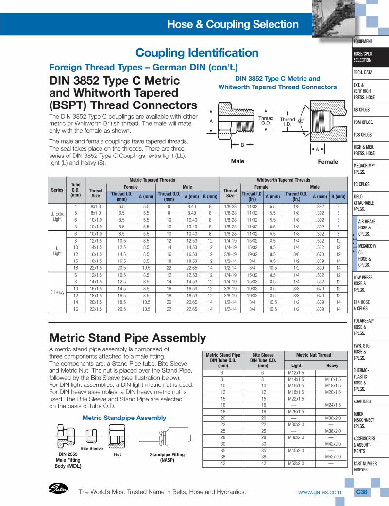
The World’s Most Trusted Name in Belts, Hose and Hydraulics.®
®
www.gates.com C38
EQUIPMENT
HOSE/CPLG.SELECTION
TECH. DATA
EXT. & VERY HIGHPRESS. HOSE
GS CPLGS.
PCM CPLGS.
PCS CPLGS.
HIGH & MED.PRESS. HOSE
MEGACRIMP®
CPLGS.
PC CPLGS.
FIELD ATTACHABLECPLGS.
AIR BRAKEHOSE & CPLGS.
MEGATECH®/ C5HOSE & CPLGS.
LOW PRESS.HOSE & CPLGS.
C14 HOSE& CPLGS.
POLARSEAL®
HOSE & CPLGS.
PWR. STG.HOSE & CPLGS.
THERMO-PLASTICHOSE & CPLGS.
ADAPTERS
QUICK DISCONNECTCPLGS.
ACCESSORIES& ASSORT-MENTS
PART NUMBERINDEXES
FL
EE
T
Hose & Coupling Selection
Foreign Thread Types – German DIN (con’t.)
DIN 3852 Type C Metricand Whitworth Tapered(BSPT) Thread ConnectorsThe DIN 3852 Type C couplings are available with eithermetric or Whitworth British thread. The male will mateonly with the female as shown.
The male and female couplings have tapered threads.The seal takes place on the threads. There are threeseries of DIN 3852 Type C Couplings: extra light (LL),light (L) and heavy (S).
DIN 3852 Type C Metric andWhitworth Tapered Thread Connectors
Male Female
Metric Stand Pipe AssemblyA metric stand pipe assembly is comprised ofthree components attached to a male fitting.The components are: a Stand Pipe tube, Bite Sleeveand Metric Nut. The nut is placed over the Stand Pipe,followed by the Bite Sleeve (see illustration below).For DIN light assemblies, a DIN light metric nut is used.For DIN heavy assemblies, a DIN heavy metric nut isused. The Bite Sleeve and Stand Pipe are selectedon the basis of tube O.D.
6 6 M12x1.5 —8 8 M14x1.5 M16x1.510 10 M16x1.5 M18x1.512 12 M18x1.5 M20x1.515 15 M22x1.5 —16 16 — M24x1.518 18 M26x1.5 —20 20 — M30x2.022 22 M30x2.0 —25 25 — M36x2.028 28 M36x2.0 —30 30 — M42x2.035 35 M45x2.0 —38 38 — M52x2.042 42 M52x2.0 —
Metric Stand Pipe Bite Sleeve Metric Nut ThreadDIN Tube O.D. DIN Tube O.D.
(mm) (mm) Light Heavy
Metric Standpipe Assembly
DIN 2353Male FittingBody (MDL)
Coupling Identification
SeriesTubeO.D.
(mm)
Metric Tapered Threads Whitworth Tapered Threads
ThreadSize
Female MaleThread
Size
Female MaleThread I.D.
(mm) A (mm) Thread O.D.(mm) A (mm) B (mm) Thread I.D.
(In.) A (mm) Thread O.D.(In.) A (mm) B (mm)
LL ExtraLight
4 8x1.0 6.5 5.5 8 8.40 8 1/8-28 11/32 5.5 1/8 .392 85 8x1.0 6.5 5.5 8 8.40 8 1/8-28 11/32 5.5 1/8 .392 86 10x1.0 8.5 5.5 10 10.40 8 1/8-28 11/32 5.5 1/8 .392 88 10x1.0 8.5 5.5 10 10.40 8 1/8-28 11/32 5.5 1/8 .392 8
LLight
6 10x1.0 8.5 5.5 10 10.40 8 1/8-28 11/32 5.5 1/8 .392 88 12x1.5 10.5 8.5 12 12.53 12 1/4-19 15/32 8.5 1/4 .532 1210 14x1.5 12.5 8.5 14 14.53 12 1/4-19 15/32 8.5 1/4 .532 1212 16x1.5 14.5 8.5 16 16.53 12 3/8-19 19/32 8.5 3/8 .670 1215 18x1.5 16.5 8.5 18 18.53 12 1/2-14 3/4 8.5 1/2 .839 1418 22x1.5 20.5 10.5 22 22.65 14 1/2-14 3/4 10.5 1/2 .839 14
S Heavy
6 12x1.5 10.5 8.5 12 12.53 12 1/4-19 15/32 8.5 1/4 .532 128 14x1.5 12.5 8.5 14 14.53 12 1/4-19 15/32 8.5 1/4 .532 1210 16x1.5 14.5 8.5 16 16.53 12 3/8-19 19/32 8.5 3/8 .670 1212 18x1.5 16.5 8.5 18 18.53 12 3/8-19 19/32 8.5 3/8 .670 1214 20x1.5 18.5 10.5 20 20.65 14 1/2-14 3/4 10.5 1/2 .839 1416 22x1.5 20.5 10.5 22 22.65 14 1/2-14 3/4 10.5 1/2 .839 14
Standpipe Fitting(NASP)
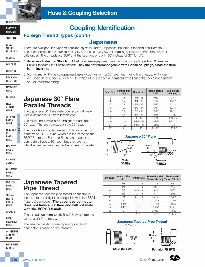
Gates CorporationC39 www.gates.com ®
®
EQUIPMENT
HOSE/CPLG.SELECTION
TECH. DATA
EXT. & VERY HIGHPRESS. HOSE
GS CPLGS.
PCM CPLGS.
PCS CPLGS.
HIGH & MED.PRESS. HOSE
MEGACRIMP®
CPLGS.
PC CPLGS.
FIELD ATTACHABLECPLGS.
AIR BRAKEHOSE &CPLGS.
MEGATECH®/C5HOSE &CPLGS.
LOW PRESS.HOSE & CPLGS.
C14 HOSE& CPLGS.
POLARSEAL®
HOSE & CPLGS.
PWR. STG.HOSE & CPLGS.
THERMO-PLASTICHOSE & CPLGS.
ADAPTERS
QUICK DISCONNECTCPLGS.
ACCESSORIES& ASSORT-MENTS
PART NUMBERINDEXES
FL
EE
T
Hose & Coupling Selection
Foreign Thread Types (con’t.)Japanese
There are two popular types of coupling styles in Japan, Japanese Industrial Standard and Komatsu.These couplings look similar to Male JIC and Female JIC Swivel couplings. However there are two majordifferences: The threads are BSP and the seat angle is only 30° instead of 37° for JIC.
1. Japanese Industrial Standard. Most Japanese equipment uses this type of coupling with a 30° seat andBritish Standard Pipe Parallel threads.They are not interchangeable with British couplings, since the flareis not inverted.
2. Komatsu. All Komatsu equipment uses couplings with a 30° seat and metric fine threads. All flangesare Code 61 or Code 62, except -10 which utilizes a special Komatsu-style flange that does not conformto SAE standard sizing.
Japanese 30° FlareParallel ThreadsThe Japanese 30° flare male connector will matewith a Japanese 30° flare female only.
The male and female have straight threads and a30° seat. The seal is made on the 30° seat.
The threads on the Japanese 30° flare connector conform to JIS B 0202, which are the same as theBSPOR threads. Both the British and Japaneseconnectors have a 30° seat, but they are notinterchangeable because the British seat is inverted.
Male
ThreadO.D.
Female
ThreadI.D.
30o30o
Japanese 30° Flare
Male(MJIS)
Female(FJISX)
Japanese TaperedPipe ThreadThe Japanese tapered pipe thread connector isidentical to and fully interchangeable with the BSPT(tapered) connector. The Japanese connectordoes not have a 30° flare and will not matewith the BSPOR female.
The threads conform to JIS B 0203, which are thesame as BSPT threads.
The seal on the Japanese tapered pipe thread connector is made on the threads.
Male (MBSPT)Male
ThreadO.D.
Female
ThreadI.D.
1o47´Japanese Tapered Pipe Thread
Female (FBSPT)
Coupling Identification
Dash Size Nominal Size(In.) Thread Size Female Thread
I.D. (In.)Male Thread
O.D. (In.)
-2 1/8 1/8 – 28 11/32 3/8-4 1/4 1/4 – 19 7/16 17/32-6 3/8 3/8 – 19 19/32 21/32-8 1/2 1/2 – 14 3/4 13/16-10 5/8 5/8 – 14 13/16 29/32-12 3/4 3/4 – 14 15/16 1-1/32-16 1 1 – 11 1-13/16 1-15/16-20 1-1/4 1-1/4 – 11 1-17/32 1-21/32-24 1-1/2 1-1/2 – 11 1-25/32 1-7/8-32 2 2 – 11 2-7/32 2-11/32
Dash Size Nominal Size(In.) Thread Size Female Parallel
Thread I.D. (In.)Male Parallel
Thread O.D. (In.)
-2 1/8 1/8 – 28 11/32 3/8-4 1/4 1/4 – 19 7/16 17/32-6 3/8 3/8 – 19 19/32 21/32-8 1/2 1/2 – 14 3/4 13/16-12 3/4 3/4 – 14 15/16 1-1/32-16 1 1 – 11 1-13/16 1-15/16-20 1-1/4 1-1/4 – 11 1-17/32 1-21/32-24 1-1/2 1-1/2 – 11 1-25/32 1-7/8-32 2 2 – 11 2-7/32 1-11/32-32 2 2 – 11 2-7/32 2-11/32
(pitch)
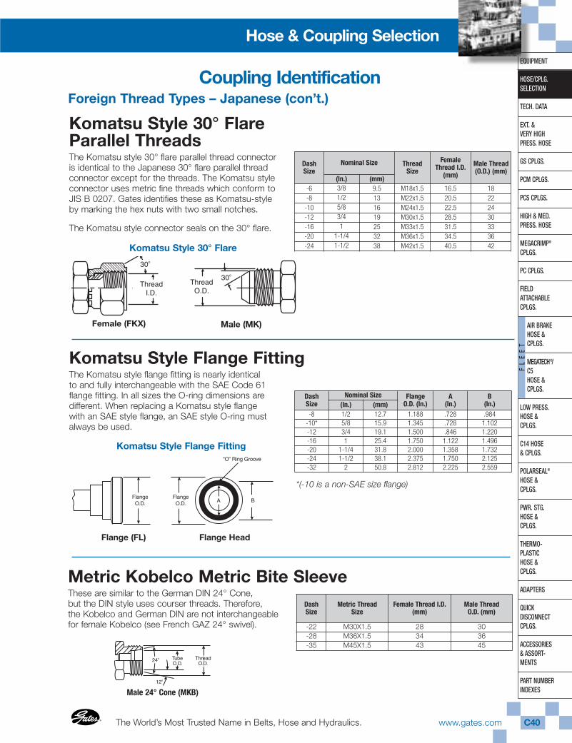
The World’s Most Trusted Name in Belts, Hose and Hydraulics.®
®
www.gates.com C40
EQUIPMENT
HOSE/CPLG.SELECTION
TECH. DATA
EXT. & VERY HIGHPRESS. HOSE
GS CPLGS.
PCM CPLGS.
PCS CPLGS.
HIGH & MED.PRESS. HOSE
MEGACRIMP®
CPLGS.
PC CPLGS.
FIELD ATTACHABLECPLGS.
AIR BRAKEHOSE & CPLGS.
MEGATECH®/ C5HOSE & CPLGS.
LOW PRESS.HOSE & CPLGS.
C14 HOSE& CPLGS.
POLARSEAL®
HOSE & CPLGS.
PWR. STG.HOSE & CPLGS.
THERMO-PLASTICHOSE & CPLGS.
ADAPTERS
QUICK DISCONNECTCPLGS.
ACCESSORIES& ASSORT-MENTS
PART NUMBERINDEXES
FL
EE
T
Hose & Coupling Selection
Metric Kobelco Metric Bite SleeveThese are similar to the German DIN 24° Cone,but the DIN style uses courser threads. Therefore,the Kobelco and German DIN are not interchangeablefor female Kobelco (see French GAZ 24° swivel).
Foreign Thread Types – Japanese (con’t.)
Komatsu Style 30° FlareParallel ThreadsThe Komatsu style 30° flare parallel thread connectoris identical to the Japanese 30° flare parallel thread connector except for the threads. The Komatsu styleconnector uses metric fine threads which conform to JIS B 0207. Gates identifies these as Komatsu-styleby marking the hex nuts with two small notches.
The Komatsu style connector seals on the 30° flare.
30o
30o
ThreadO.D.
ThreadI.D.
Swivel Female(FKX)
Solid Male(MK)
Komatsu Style 30° Flare
Female (FKX)
Komatsu Style Flange FittingThe Komatsu style flange fitting is nearly identicalto and fully interchangeable with the SAE Code 61flange fitting. In all sizes the O-ring dimensions aredifferent. When replacing a Komatsu style flangewith an SAE style flange, an SAE style O-ring mustalways be used.
*(-10 is a non-SAE size flange)
Komatsu Style Flange Fitting
Flange (FL) Flange Head
Male (MK)
Coupling Identification
DashSize
Nominal Size ThreadSize
FemaleThread I.D.
(mm)
Male Thread(O.D.) (mm)
(In.) (mm)-6 3/8 9.5 M18x1.5 16.5 18-8 1/2 13 M22x1.5 20.5 22-10 5/8 16 M24x1.5 22.5 24-12 3/4 19 M30x1.5 28.5 30-16 1 25 M33x1.5 31.5 33-20 1-1/4 32 M36x1.5 34.5 36-24 1-1/2 38 M42x1.5 40.5 42
Dash Size
Nominal Size Flange O.D. (In.)
A(In.)
B(In.)(In.) (mm)
-8 1/2 12.7 1.188 .728 .984-10* 5/8 15.9 1.345 .728 1.102-12 3/4 19.1 1.500 .846 1.220-16 1 25.4 1.750 1.122 1.496-20 1-1/4 31.8 2.000 1.358 1.732-24 1-1/2 38.1 2.375 1.750 2.125-32 2 50.8 2.812 2.225 2.559
DashSize
Metric Thread Size
Female Thread I.D.(mm)
Male Thread O.D. (mm)
-22 M30X1.5 28 30-28 M36X1.5 34 36-35 M45X1.5 43 45
Male 24° Cone (MKB)
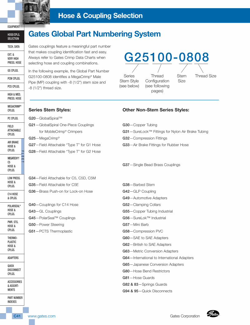
Gates CorporationC41 www.gates.com ®
®
EQUIPMENT
HOSE/CPLG.SELECTION
TECH. DATA
EXT. & VERY HIGHPRESS. HOSE
GS CPLGS.
PCM CPLGS.
PCS CPLGS.
HIGH & MED.PRESS. HOSE
MEGACRIMP®
CPLGS.
PC CPLGS.
FIELD ATTACHABLECPLGS.
AIR BRAKEHOSE &CPLGS.
MEGATECH®/C5HOSE &CPLGS.
LOW PRESS.HOSE & CPLGS.
C14 HOSE& CPLGS.
POLARSEAL®
HOSE & CPLGS.
PWR. STG.HOSE & CPLGS.
THERMO-PLASTICHOSE & CPLGS.
ADAPTERS
QUICK DISCONNECTCPLGS.
ACCESSORIES& ASSORT-MENTS
PART NUMBERINDEXES
FL
EE
T
Hose & Coupling Selection
Gates Global Part Numbering SystemGates couplings feature a meaningful part numberthat makes coupling identification fast and easy.Always refer to Gates Crimp Data Charts whenselecting hose and coupling combinations.
In the following example, the Global Part NumberG25100-0808 identifies a MegaCrimp® MalePipe (MP) coupling with -8 (1/2") stem size and-8 (1/2") thread size.
G25100-0808Series
Stem Style(see below)
ThreadConfiguration(see following
pages)
StemSize
Thread Size
Series Stem Styles:
G20—GlobalSpiral™
G21—GlobalSpiral One-Piece Couplings
for MobileCrimp® Crimpers
G25—MegaCrimp®
G27—Field Attachable “Type T” for G1 Hose
G28—Field Attachable “Type T” for G2 Hose
G34—Field Attachable for C5, C5D, C5M
G35—Field Attachable for C5E
G36—Brass Push-on for Lock-on Hose
G40—Couplings for C14 Hose
G43—GL Couplings
G45—PolarSeal™ Couplings
G50—Power Steering
G51—PCTS Thermoplastic
Other Non-Stem Series Styles:
G30—Copper Tubing
G31—SureLock™ Fittings for Nylon Air Brake Tubing
G32—Compression Fittings
G33—Air Brake Fittings for Rubber Hose
G37—Single Bead Brass Couplings
G38—Barbed Stem
G42—GLP Coupling
G49—Automotive Adapters
G52—Clamping Collars
G55—Copper Tubing Industrial
G56—SureLok™ Industrial
G57—Mini Barb
G58—Compression PVC
G60—SAE to SAE Adapters
G62—British to SAE Adapters
G63—Metric Conversion Adapters
G64—International to International Adapters
G65—Japanese Conversion Adapters
G80—Hose Bend Restrictors
G81—Hose Guards
G82 & 83—Springs Guards
G94 & 95—Quick Disconnects
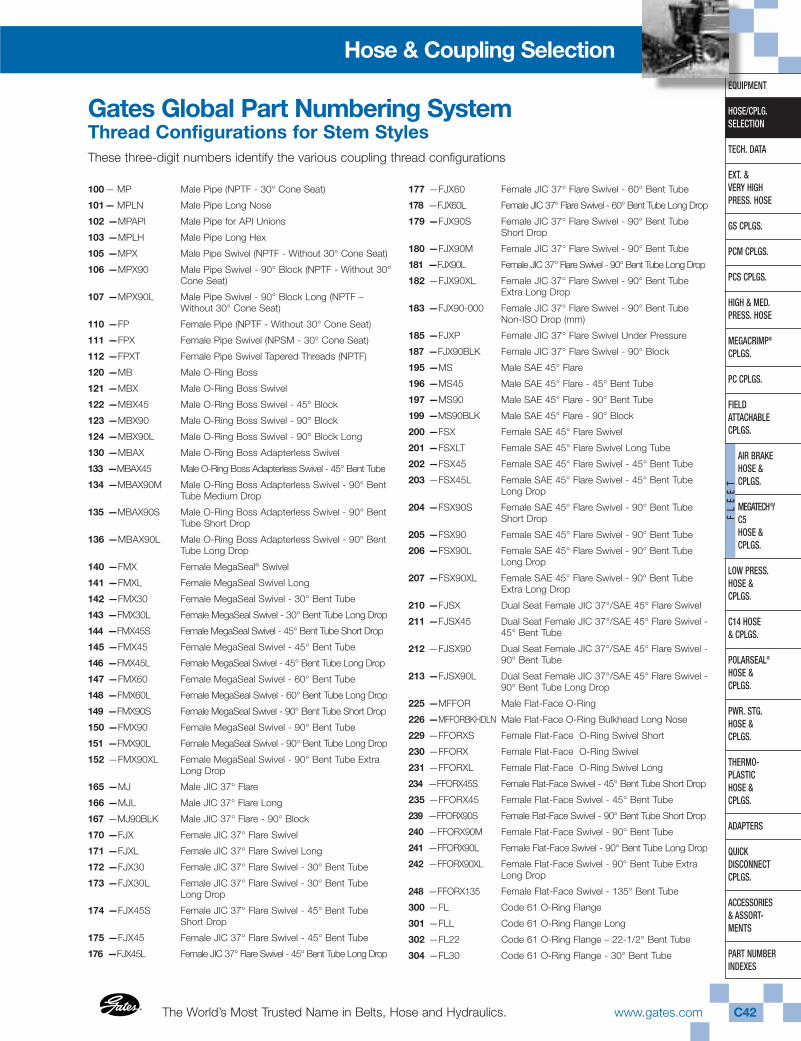
The World’s Most Trusted Name in Belts, Hose and Hydraulics.®
®
www.gates.com C42
EQUIPMENT
HOSE/CPLG.SELECTION
TECH. DATA
EXT. & VERY HIGHPRESS. HOSE
GS CPLGS.
PCM CPLGS.
PCS CPLGS.
HIGH & MED.PRESS. HOSE
MEGACRIMP®
CPLGS.
PC CPLGS.
FIELD ATTACHABLECPLGS.
AIR BRAKEHOSE & CPLGS.
MEGATECH®/ C5HOSE & CPLGS.
LOW PRESS.HOSE & CPLGS.
C14 HOSE& CPLGS.
POLARSEAL®
HOSE & CPLGS.
PWR. STG.HOSE & CPLGS.
THERMO-PLASTICHOSE & CPLGS.
ADAPTERS
QUICK DISCONNECTCPLGS.
ACCESSORIES& ASSORT-MENTS
PART NUMBERINDEXES
FL
EE
T
Hose & Coupling Selection
Thread Configurations for Stem StylesThese three-digit numbers identify the various coupling thread configurations
100— MP Male Pipe (NPTF - 30° Cone Seat)
101— MPLN Male Pipe Long Nose
102 —MPAPI Male Pipe for API Unions
103 —MPLH Male Pipe Long Hex
105 —MPX Male Pipe Swivel (NPTF - Without 30° Cone Seat)
106 —MPX90 Male Pipe Swivel - 90° Block (NPTF - Without 30°Cone Seat)
107 —MPX90L Male Pipe Swivel - 90° Block Long (NPTF –Without 30° Cone Seat)
110 —FP Female Pipe (NPTF - Without 30° Cone Seat)
111 —FPX Female Pipe Swivel (NPSM - 30° Cone Seat)
112 —FPXT Female Pipe Swivel Tapered Threads (NPTF)
120 —MB Male O-Ring Boss
121 —MBX Male O-Ring Boss Swivel
122 —MBX45 Male O-Ring Boss Swivel - 45° Block
123 —MBX90 Male O-Ring Boss Swivel - 90° Block
124 —MBX90L Male O-Ring Boss Swivel - 90° Block Long
130 —MBAX Male O-Ring Boss Adapterless Swivel
133 —MBAX45 Male O-Ring Boss Adapterless Swivel - 45° Bent Tube
134 —MBAX90M Male O-Ring Boss Adapterless Swivel - 90° BentTube Medium Drop
135 —MBAX90S Male O-Ring Boss Adapterless Swivel - 90° BentTube Short Drop
136 —MBAX90L Male O-Ring Boss Adapterless Swivel - 90° BentTube Long Drop
140 —FMX Female MegaSeal® Swivel
141 —FMXL Female MegaSeal Swivel Long
142 —FMX30 Female MegaSeal Swivel - 30° Bent Tube
143 —FMX30L Female MegaSeal Swivel - 30° Bent Tube Long Drop
144 —FMX45S Female MegaSeal Swivel - 45° Bent Tube Short Drop
145 —FMX45 Female MegaSeal Swivel - 45° Bent Tube
146 —FMX45L Female MegaSeal Swivel - 45° Bent Tube Long Drop
147 —FMX60 Female MegaSeal Swivel - 60° Bent Tube
148 —FMX60L Female MegaSeal Swivel - 60° Bent Tube Long Drop
149 —FMX90S Female MegaSeal Swivel - 90° Bent Tube Short Drop
150 —FMX90 Female MegaSeal Swivel - 90° Bent Tube
151 —FMX90L Female MegaSeal Swivel - 90° Bent Tube Long Drop
152 —FMX90XL Female MegaSeal Swivel - 90° Bent Tube ExtraLong Drop
165 —MJ Male JIC 37° Flare
166 —MJL Male JIC 37° Flare Long
167 —MJ90BLK Male JIC 37° Flare - 90° Block
170 —FJX Female JIC 37° Flare Swivel
171 —FJXL Female JIC 37° Flare Swivel Long
172 —FJX30 Female JIC 37° Flare Swivel - 30° Bent Tube
173 —FJX30L Female JIC 37° Flare Swivel - 30° Bent TubeLong Drop
174 —FJX45S Female JIC 37° Flare Swivel - 45° Bent TubeShort Drop
175 —FJX45 Female JIC 37° Flare Swivel - 45° Bent Tube
176 —FJX45L Female JIC 37° Flare Swivel - 45° Bent Tube Long Drop
177 —FJX60 Female JIC 37° Flare Swivel - 60° Bent Tube
178 —FJX60L Female JIC 37° Flare Swivel - 60° Bent Tube Long Drop
179 —FJX90S Female JIC 37° Flare Swivel - 90° Bent TubeShort Drop
180 —FJX90M Female JIC 37° Flare Swivel - 90° Bent Tube
181 —FJX90L Female JIC 37° Flare Swivel - 90° Bent Tube Long Drop
182 —FJX90XL Female JIC 37° Flare Swivel - 90° Bent TubeExtra Long Drop
183 —FJX90-000 Female JIC 37° Flare Swivel - 90° Bent Tube Non-ISO Drop (mm)
185 —FJXP Female JIC 37° Flare Swivel Under Pressure
187 —FJX90BLK Female JIC 37° Flare Swivel - 90° Block
195 —MS Male SAE 45° Flare
196 —MS45 Male SAE 45° Flare - 45° Bent Tube
197 —MS90 Male SAE 45° Flare - 90° Bent Tube
199 —MS90BLK Male SAE 45° Flare - 90° Block
200 —FSX Female SAE 45° Flare Swivel
201 —FSXLT Female SAE 45° Flare Swivel Long Tube
202 —FSX45 Female SAE 45° Flare Swivel - 45° Bent Tube
203 —FSX45L Female SAE 45° Flare Swivel - 45° Bent TubeLong Drop
204 —FSX90S Female SAE 45° Flare Swivel - 90° Bent TubeShort Drop
205 —FSX90 Female SAE 45° Flare Swivel - 90° Bent Tube
206 —FSX90L Female SAE 45° Flare Swivel - 90° Bent TubeLong Drop
207 —FSX90XL Female SAE 45° Flare Swivel - 90° Bent TubeExtra Long Drop
210 —FJSX Dual Seat Female JIC 37°/SAE 45° Flare Swivel
211 —FJSX45 Dual Seat Female JIC 37°/SAE 45° Flare Swivel -45° Bent Tube
212 —FJSX90 Dual Seat Female JIC 37°/SAE 45° Flare Swivel -90° Bent Tube
213 —FJSX90L Dual Seat Female JIC 37°/SAE 45° Flare Swivel -90° Bent Tube Long Drop
225 —MFFOR Male Flat-Face O-Ring
226 —MFFORBKHDLN Male Flat-Face O-Ring Bulkhead Long Nose
229 —FFORXS Female Flat-Face O-Ring Swivel Short
230 —FFORX Female Flat-Face O-Ring Swivel
231 —FFORXL Female Flat-Face O-Ring Swivel Long
234 —FFORX45S Female Flat-Face Swivel - 45° Bent Tube Short Drop
235 —FFORX45 Female Flat-Face Swivel - 45° Bent Tube
239 —FFORX90S Female Flat-Face Swivel - 90° Bent Tube Short Drop
240 —FFORX90M Female Flat-Face Swivel - 90° Bent Tube
241 —FFORX90L Female Flat-Face Swivel - 90° Bent Tube Long Drop
242 —FFORX90XL Female Flat-Face Swivel - 90° Bent Tube ExtraLong Drop
248 —FFORX135 Female Flat-Face Swivel - 135° Bent Tube
300 —FL Code 61 O-Ring Flange
301 —FLL Code 61 O-Ring Flange Long
302 —FL22 Code 61 O-Ring Flange – 22-1/2° Bent Tube
304 —FL30 Code 61 O-Ring Flange - 30° Bent Tube
Gates Global Part Numbering System
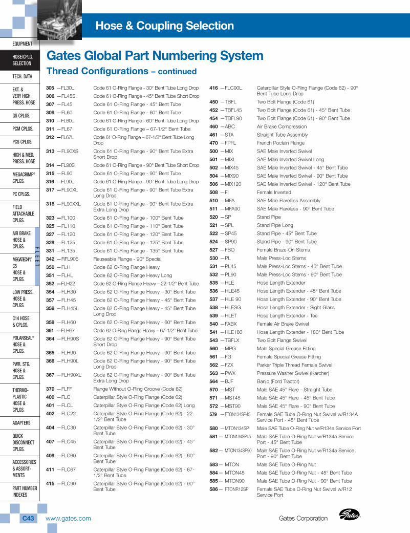
Gates CorporationC43 www.gates.com ®
®
EQUIPMENT
HOSE/CPLG.SELECTION
TECH. DATA
EXT. & VERY HIGHPRESS. HOSE
GS CPLGS.
PCM CPLGS.
PCS CPLGS.
HIGH & MED.PRESS. HOSE
MEGACRIMP®
CPLGS.
PC CPLGS.
FIELD ATTACHABLECPLGS.
AIR BRAKEHOSE &CPLGS.
MEGATECH®/C5HOSE &CPLGS.
LOW PRESS.HOSE & CPLGS.
C14 HOSE& CPLGS.
POLARSEAL®
HOSE & CPLGS.
PWR. STG.HOSE & CPLGS.
THERMO-PLASTICHOSE & CPLGS.
ADAPTERS
QUICK DISCONNECTCPLGS.
ACCESSORIES& ASSORT-MENTS
PART NUMBERINDEXES
FL
EE
T
Hose & Coupling Selection
Gates Global Part Numbering SystemThread Configurations – continued
305 —FL30L Code 61 O-Ring Flange - 30° Bent Tube Long Drop
306 —FL45S Code 61 O-Ring Flange - 45° Bent Tube Short Drop
307 —FL45 Code 61 O-Ring Flange - 45° Bent Tube
309 —FL60 Code 61 O-Ring Flange - 60° Bent Tube
310 —FL60L Code 61 O-Ring Flange - 60° Bent Tube Long Drop
311 —FL67 Code 61 O-Ring Flange – 67-1/2° Bent Tube
312 —FL67L Code 61 O-Ring Flange – 67-1/2° Bent Tube LongDrop
313 —FL90XS Code 61 O-Ring Flange - 90° Bent Tube ExtraShort Drop
314 —FL90S Code 61 O-Ring Flange - 90° Bent Tube Short Drop
315 —FL90 Code 61 O-Ring Flange - 90° Bent Tube
316 —FL90L Code 61 O-Ring Flange - 90° Bent Tube Long Drop
317 —FL90XL Code 61 O-Ring Flange - 90° Bent Tube ExtraLong Drop
318 —FL90XXL Code 61 O-Ring Flange - 90° Bent Tube ExtraExtra Long Drop
323 —FL100 Code 61 O-Ring Flange - 100° Bent Tube
325 —FL110 Code 61 O-Ring Flange - 110° Bent Tube
327 —FL120 Code 61 O-Ring Flange - 120° Bent Tube
329 —FL125 Code 61 O-Ring Flange - 125° Bent Tube
331 —FL135 Code 61 O-Ring Flange - 135° Bent Tube
342 —RFL905 Reuseable Flange - 90° Special
350 —FLH Code 62 O-Ring Flange Heavy
351 —FLHL Code 62 O-Ring Flange Heavy Long
352 —FLH22 Code 62 O-Ring Flange Heavy – 22-1/2° Bent Tube
354 —FLH30 Code 62 O-Ring Flange Heavy - 30° Bent Tube
357 —FLH45 Code 62 O-Ring Flange Heavy - 45° Bent Tube
358 —FLH45L Code 62 O-Ring Flange Heavy - 45° Bent TubeLong Drop
359 —FLH60 Code 62 O-Ring Flange Heavy - 60° Bent Tube
361 —FLH67 Code 62 O-Ring Flange Heavy – 67-1/2° Bent Tube
364 —FLH90S Code 62 O-Ring Flange Heavy - 90° Bent TubeShort Drop
365 —FLH90 Code 62 O-Ring Flange Heavy - 90° Bent Tube
366 —FLH90L Code 62 O-Ring Flange Heavy - 90° Bent TubeLong Drop
367 —FLH90XL Code 62 O-Ring Flange Heavy - 90° Bent TubeExtra Long Drop
370 —FLFF Flange Without O-Ring Groove (Code 62)
400 —FLC Caterpillar Style O-Ring Flange (Code 62)
401 —FLCL Caterpillar Style O-Ring Flange (Code 62) Long
402 —FLC22 Caterpillar Style O-Ring Flange (Code 62) - 22-1/2° Bent Tube
404 —FLC30 Caterpillar Style O-Ring Flange (Code 62) - 30°Bent Tube
407 —FLC45 Caterpillar Style O-Ring Flange (Code 62) - 45°Bent Tube
409 —FLC60 Caterpillar Style O-Ring Flange (Code 62) - 60°Bent Tube
411 —FLC67 Caterpillar Style O-Ring Flange (Code 62) - 67-1/2° Bent Tube
415 —FLC90 Caterpillar Style O-Ring Flange (Code 62) - 90°Bent Tube
416 —FLC90L Caterpillar Style O-Ring Flange (Code 62) - 90°Bent Tube Long Drop
450 —TBFL Two Bolt Flange (Code 61)
452 —TBFL45 Two Bolt Flange (Code 61) - 45° Bent Tube
454 —TBFL90 Two Bolt Flange (Code 61) - 90° Bent Tube
460 —ABC Air Brake Compression
461 —STA Straight Tube Assembly
470 —FPFL French Poclain Flange
500 —MIX SAE Male Inverted Swivel
501 —MIXL SAE Male Inverted Swivel Long
502 —MIX45 SAE Male Inverted Swivel - 45° Bent Tube
504 —MIX90 SAE Male Inverted Swivel - 90° Bent Tube
506 —MIX120 SAE Male Inverted Swivel - 120° Bent Tube
508 —FI Female Inverted
510 —MFA SAE Male Flareless Assembly
511 —MFA90 SAE Male Flareless - 90° Bent Tube
520 —SP Stand Pipe
521 —SPL Stand Pipe Long
522 —SP45 Stand Pipe - 45° Bent Tube
524 —SP90 Stand Pipe - 90° Bent Tube
527 —FBO Female Braze-On Stems
530 —PL Male Press-Loc Stems
531 —PL45 Male Press-Loc Stems - 45° Bent Tube
532 —PL90 Male Press-Loc Stems - 90° Bent Tube
535 —HLE Hose Length Extender
536 —HLE45 Hose Length Extender - 45° Bent Tube
537 —HLE 90 Hose Length Extender - 90° Bent Tube
538 —HLESG Hose Length Extender - Sight Glass
539 —HLET Hose Length Extender - Tee
540 —FABX Female Air Brake Swivel
541 —HLE180 Hose Length Extender - 180° Bent Tube
543 —TBFLX Two Bolt Flange Swivel
560 —MPG Male Special Grease Fitting
561 —FG Female Special Grease Fitting
562 —FZX Parker Triple Thread Female Swivel
563 —PWX Pressure Washer Swivel (Karcher)
564 —BJF Banjo (Ford Tractor)
570 —MST Male SAE 45° Flare - Straight Tube
571 —MST45 Male SAE 45° Flare - 45° Bent Tube
572 —MST90 Male SAE 45° Flare - 90° Bent Tube
579 —FTON134SP45 Female SAE Tube O-Ring Nut Swivel w/R134AService Port - 45° Bent Tube
580 —MTON134SP Male SAE Tube O-Ring Nut w/R134a Service Port
581— MTON134SP45 Male SAE Tube O-Ring Nut w/R134a ServicePort - 45° Bent Tube
582— MTON134SP90 Male SAE Tube O-Ring Nut w/R134a ServicePort - 90° Bent Tube
583— MTON Male SAE Tube O-Ring Nut
584— MTON45 Male SAE Tube O-Ring Nut - 45° Bent Tube
585— MTON90 Male SAE Tube O-Ring Nut - 90° Bent Tube
586— FTONR12SP Female SAE Tube O-Ring Nut Swivel w/R12Service Port
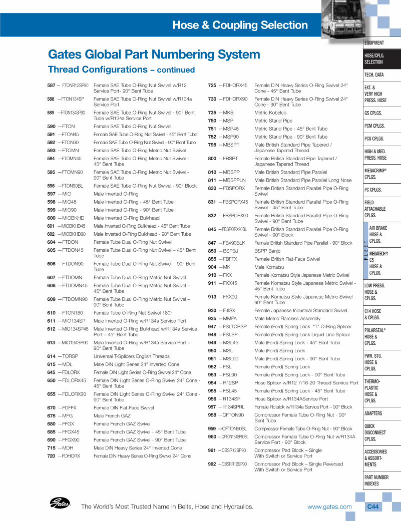
The World’s Most Trusted Name in Belts, Hose and Hydraulics.®
®
www.gates.com C44
EQUIPMENT
HOSE/CPLG.SELECTION
TECH. DATA
EXT. & VERY HIGHPRESS. HOSE
GS CPLGS.
PCM CPLGS.
PCS CPLGS.
HIGH & MED.PRESS. HOSE
MEGACRIMP®
CPLGS.
PC CPLGS.
FIELD ATTACHABLECPLGS.
AIR BRAKEHOSE & CPLGS.
MEGATECH®/ C5HOSE & CPLGS.
LOW PRESS.HOSE & CPLGS.
C14 HOSE& CPLGS.
POLARSEAL®
HOSE & CPLGS.
PWR. STG.HOSE & CPLGS.
THERMO-PLASTICHOSE & CPLGS.
ADAPTERS
QUICK DISCONNECTCPLGS.
ACCESSORIES& ASSORT-MENTS
PART NUMBERINDEXES
FL
EE
T
Hose & Coupling Selection
Gates Global Part Numbering SystemThread Configurations – continued
587— FTONR12SP90 Female SAE Tube O-Ring Nut Swivel w/R12Service Port- 90° Bent Tube
588 —FTON134SP Female SAE Tube O-Ring Nut Swivel w/R134aService Port
589 —FTON134SP90 Female SAE Tube O-Ring Nut Swivel - 90° BentTube w/R134a Service Port
590 —FTON Female SAE Tube O-Ring Nut Swivel
591 —FTON45 Female SAE Tube O-Ring Nut Swivel - 45° Bent Tube
592 —FTON90 Female SAE Tube O-Ring Nut Swivel - 90° Bent Tube
593 —FTOMN Female SAE Tube O-Ring Metric Nut Swivel
594 —FTOMN45 Female SAE Tube O-Ring Metric Nut Swivel -45° Bent Tube
595 —FTOMN90 Female SAE Tube O-Ring Metric Nut Swivel -90° Bent Tube
596 —FTON90BL Female SAE Tube O-Ring Nut Swivel - 90° Block
597 —MIO Male Inverted O-Ring
598 —MIO45 Male Inverted O-Ring - 45° Bent Tube
599 —MIO90 Male Inverted O-Ring - 90° Bent Tube
600 —MIOBKHD Male Inverted O-Ring Bulkhead
601 —MIOBKHD45 Male Inverted O-Ring Bulkhead - 45° Bent Tube
602 —MIOBKHD90 Male Inverted O-Ring Bulkhead - 90° Bent Tube
604 —FTDON Female Tube Dual O-Ring Nut Swivel
605 —FTDON45 Female Tube Dual O-Ring Nut Swivel – 45° BentTube
606 —FTDON90 Female Tube Dual O-Ring Nut Swivel – 90° BentTube
607 —FTDOMN Female Tube Dual O-Ring Metric Nut Swivel
608 —FTDOMN45 Female Tube Dual O-Ring Metric Nut Swivel – 45° Bent Tube
609 —FTDOMN90 Female Tube Dual O-Ring Metric Nut Swivel –90° Bent Tube
610 —FTON180 Female Tube O-Ring Nut Swivel 180°
611 —MIO134SP Male Inverted O-Ring w/R134a Service Port
612 —MIO134SP45 Male Inverted O-Ring Bulkhead w/R134a ServicePort – 45° Bent Tube
613 —MIO134SP90 Male Inverted O-Ring w/R134a Service Port –90° Bent Tube
614 —TORSP Universal T-Splicers English Threads
615 —MDL Male DIN Light Series 24° Inverted Cone
645 —FDLORX Female DIN Light Series O-Ring Swivel 24° Cone
650 —FDLORX45 Female DIN Light Series O-Ring Swivel 24° Cone -45° Bent Tube
655 —FDLORX90 Female DIN Light Series O-Ring Swivel 24° Cone -90° Bent Tube
670 —FDFFX Female DIN Flat-Face Swivel
675 —MFG Male French GAZ
680 —FFGX Female French GAZ Swivel
685 —FFGX45 Female French GAZ Swivel - 45° Bent Tube
690 —FFGX90 Female French GAZ Swivel - 90° Bent Tube
715 —MDH Male DIN Heavy Series 24° Inverted Cone
720 —FDHORX Female DIN Heavy Series O-Ring Swivel 24° Cone
725 —FDHORX45 Female DIN Heavy Series O-Ring Swivel 24°Cone - 45° Bent Tube
730 —FDHORX90 Female DIN Heavy Series O-Ring Swivel 24°Cone - 90° Bent Tube
735 —MKB Metric Kobelco
750 —MSP Metric Stand Pipe
751 —MSP45 Metric Stand Pipe - 45° Bent Tube
752 —MSP90 Metric Stand Pipe - 90° Bent Tube
795 —MBSPT Male British Standard Pipe Tapered /Japanese Tapered Thread
800 —FBSPT Female British Standard Pipe Tapered /Japanese Tapered Thread
810 —MBSPP Male British Standard Pipe Parallel
811 —MBSPPLN Male British Standard Pipe Parallel Long Nose
830 —FBSPORX Female British Standard Parallel Pipe O-RingSwivel
831 —FBSPORX45 Female British Standard Parallel Pipe O-RingSwivel - 45° Bent Tube
832 —FBSPORX90 Female British Standard Parallel Pipe O-RingSwivel - 90° Bent Tube
845 —FBSPORX90BL Female British Standard Parallel Pipe O-RingSwivel - 90° Block
847 —FBX90BLK Female British Standard Pipe Parallel - 90° Block
850 —BSPBJ BSPP Banjo
855 —FBFFX Female British Flat-Face Swivel
904 —MK Male Komatsu
910 —FKX Female Komatsu Style Japanese Metric Swivel
911 —FKX45 Female Komatsu Style Japanese Metric Swivel -45° Bent Tube
913 —FKX90 Female Komatsu Style Japanese Metric Swivel -90° Bent Tube
930 —FJISX Female Japanese Industrial Standard Swivel
935 —MMFA Male Metric Flareless Assembly
947 —FSLTORSP Female (Ford) Spring Lock “T” O-Ring Splicer
948 —FSLSP Female (Ford) Spring Lock Liquid Line Splicer
949 —MSL45 Male (Ford) Spring Lock - 45° Bent Tube
950 —MSL Male (Ford) Spring Lock
951 —MSL90 Male (Ford) Spring Lock - 90° Bent Tube
952 —FSL Female (Ford) Spring Lock
953 —FSL90 Female (Ford) Spring Lock - 90° Bent Tube
954 —R12SP Hose Splicer w/R12 7/16-20 Thread Service Port
955 —FSL45 Female (Ford) Spring Lock - 45° Bent Tube
956 —R134SP Hose Splicer w/R134AService Port
957 —R134SPRL Female Rotalok w/R134a Service Port – 90° Block
958 —CFTON90 Compressor Female Tube O-Ring Nut - 90°Bent Tube
959 —CFTON90BL Compressor Female Tube O-Ring Nut - 90° Block
960 —CFTON134SP90BL Compressor Female Tube O-Ring Nut w/R134AService Port - 90° Block
961 —CBSR12SP90 Compressor Pad Block – Single With Switch or Service Port
962 —CBSRR12SP90 Compressor Pad Block – Single ReversedWith Switch or Service Port
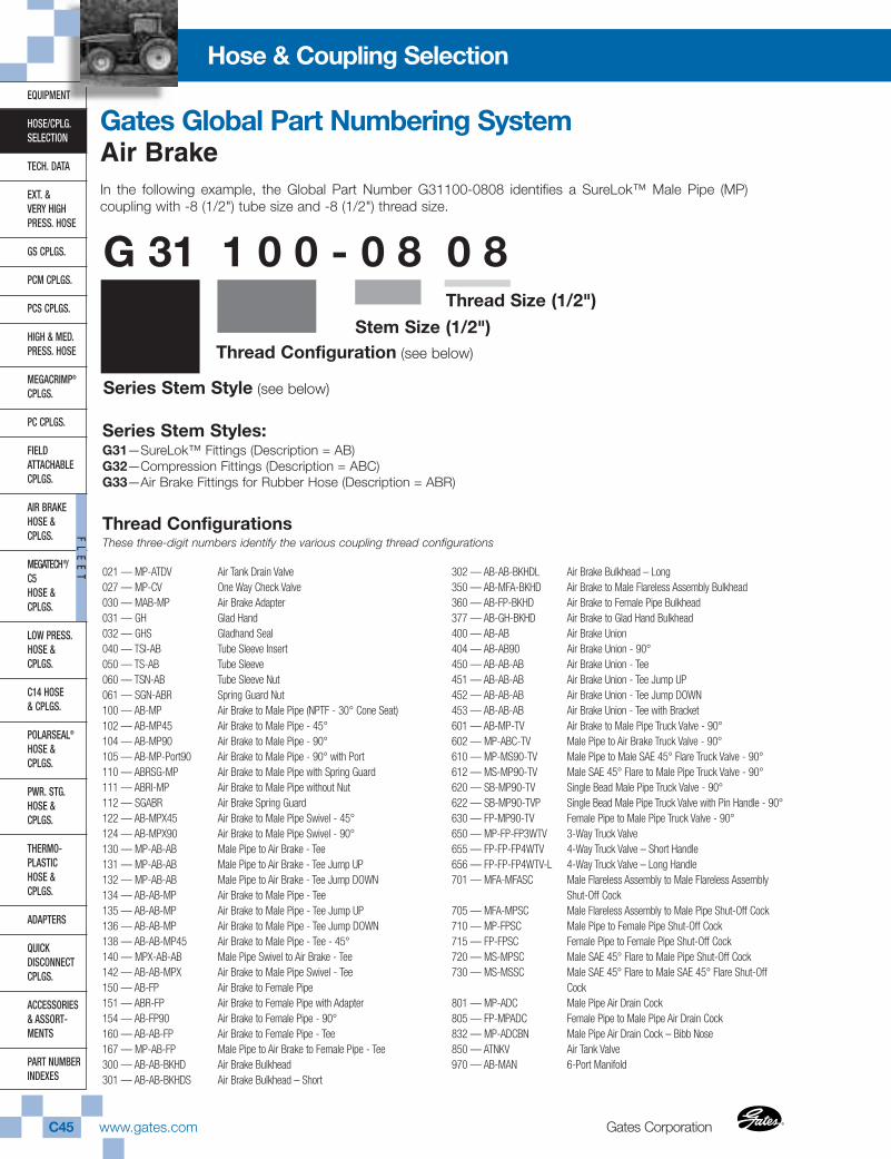
Gates CorporationC45 www.gates.com ®
®
EQUIPMENT
HOSE/CPLG.SELECTION
TECH. DATA
EXT. & VERY HIGHPRESS. HOSE
GS CPLGS.
PCM CPLGS.
PCS CPLGS.
HIGH & MED.PRESS. HOSE
MEGACRIMP®
CPLGS.
PC CPLGS.
FIELD ATTACHABLECPLGS.
AIR BRAKEHOSE &CPLGS.
MEGATECH®/C5HOSE &CPLGS.
LOW PRESS.HOSE & CPLGS.
C14 HOSE& CPLGS.
POLARSEAL®
HOSE & CPLGS.
PWR. STG.HOSE & CPLGS.
THERMO-PLASTICHOSE & CPLGS.
ADAPTERS
QUICK DISCONNECTCPLGS.
ACCESSORIES& ASSORT-MENTS
PART NUMBERINDEXES
FL
EE
T
Hose & Coupling Selection
G 31 1 0 0 - 0 8 0 8Thread Size (1/2")
Stem Size (1/2")Thread Configuration (see below)
Series Stem Style (see below)
Series Stem Styles:G31—SureLok™ Fittings (Description = AB)G32—Compression Fittings (Description = ABC)G33—Air Brake Fittings for Rubber Hose (Description = ABR)
Thread ConfigurationsThese three-digit numbers identify the various coupling thread configurations
In the following example, the Global Part Number G31100-0808 identifies a SureLok™ Male Pipe (MP)coupling with -8 (1/2") tube size and -8 (1/2") thread size.
Gates Global Part Numbering SystemAir Brake
021 — MP-ATDV Air Tank Drain Valve027 — MP-CV One Way Check Valve030 — MAB-MP Air Brake Adapter031 — GH Glad Hand032 — GHS Gladhand Seal040 — TSI-AB Tube Sleeve Insert050 — TS-AB Tube Sleeve060 — TSN-AB Tube Sleeve Nut061 — SGN-ABR Spring Guard Nut100 — AB-MP Air Brake to Male Pipe (NPTF - 30° Cone Seat)102 — AB-MP45 Air Brake to Male Pipe - 45°104 — AB-MP90 Air Brake to Male Pipe - 90°105 — AB-MP-Port90 Air Brake to Male Pipe - 90° with Port110 — ABRSG-MP Air Brake to Male Pipe with Spring Guard111 — ABRI-MP Air Brake to Male Pipe without Nut112 — SGABR Air Brake Spring Guard122 — AB-MPX45 Air Brake to Male Pipe Swivel - 45°124 — AB-MPX90 Air Brake to Male Pipe Swivel - 90°130 — MP-AB-AB Male Pipe to Air Brake - Tee131 — MP-AB-AB Male Pipe to Air Brake - Tee Jump UP132 — MP-AB-AB Male Pipe to Air Brake - Tee Jump DOWN134 — AB-AB-MP Air Brake to Male Pipe - Tee135 — AB-AB-MP Air Brake to Male Pipe - Tee Jump UP136 — AB-AB-MP Air Brake to Male Pipe - Tee Jump DOWN138 — AB-AB-MP45 Air Brake to Male Pipe - Tee - 45°140 — MPX-AB-AB Male Pipe Swivel to Air Brake - Tee142 — AB-AB-MPX Air Brake to Male Pipe Swivel - Tee150 — AB-FP Air Brake to Female Pipe151 — ABR-FP Air Brake to Female Pipe with Adapter154 — AB-FP90 Air Brake to Female Pipe - 90°160 — AB-AB-FP Air Brake to Female Pipe - Tee167 — MP-AB-FP Male Pipe to Air Brake to Female Pipe - Tee300 — AB-AB-BKHD Air Brake Bulkhead301 — AB-AB-BKHDS Air Brake Bulkhead – Short
302 — AB-AB-BKHDL Air Brake Bulkhead – Long350 — AB-MFA-BKHD Air Brake to Male Flareless Assembly Bulkhead360 — AB-FP-BKHD Air Brake to Female Pipe Bulkhead377 — AB-GH-BKHD Air Brake to Glad Hand Bulkhead400 — AB-AB Air Brake Union404 — AB-AB90 Air Brake Union - 90°450 — AB-AB-AB Air Brake Union - Tee451 — AB-AB-AB Air Brake Union - Tee Jump UP452 — AB-AB-AB Air Brake Union - Tee Jump DOWN453 — AB-AB-AB Air Brake Union - Tee with Bracket601 — AB-MP-TV Air Brake to Male Pipe Truck Valve - 90°602 — MP-ABC-TV Male Pipe to Air Brake Truck Valve - 90°610 — MP-MS90-TV Male Pipe to Male SAE 45° Flare Truck Valve - 90°612 — MS-MP90-TV Male SAE 45° Flare to Male Pipe Truck Valve - 90°620 — SB-MP90-TV Single Bead Male Pipe Truck Valve - 90°622 — SB-MP90-TVP Single Bead Male Pipe Truck Valve with Pin Handle - 90°630 — FP-MP90-TV Female Pipe to Male Pipe Truck Valve - 90°650 — MP-FP-FP3WTV 3-Way Truck Valve655 — FP-FP-FP4WTV 4-Way Truck Valve – Short Handle656 — FP-FP-FP4WTV-L 4-Way Truck Valve – Long Handle701 — MFA-MFASC Male Flareless Assembly to Male Flareless Assembly
Shut-Off Cock705 — MFA-MPSC Male Flareless Assembly to Male Pipe Shut-Off Cock710 — MP-FPSC Male Pipe to Female Pipe Shut-Off Cock715 — FP-FPSC Female Pipe to Female Pipe Shut-Off Cock720 — MS-MPSC Male SAE 45° Flare to Male Pipe Shut-Off Cock730 — MS-MSSC Male SAE 45° Flare to Male SAE 45° Flare Shut-Off
Cock801 — MP-ADC Male Pipe Air Drain Cock805 — FP-MPADC Female Pipe to Male Pipe Air Drain Cock832 — MP-ADCBN Male Pipe Air Drain Cock – Bibb Nose850 — ATNKV Air Tank Valve970 — AB-MAN 6-Port Manifold
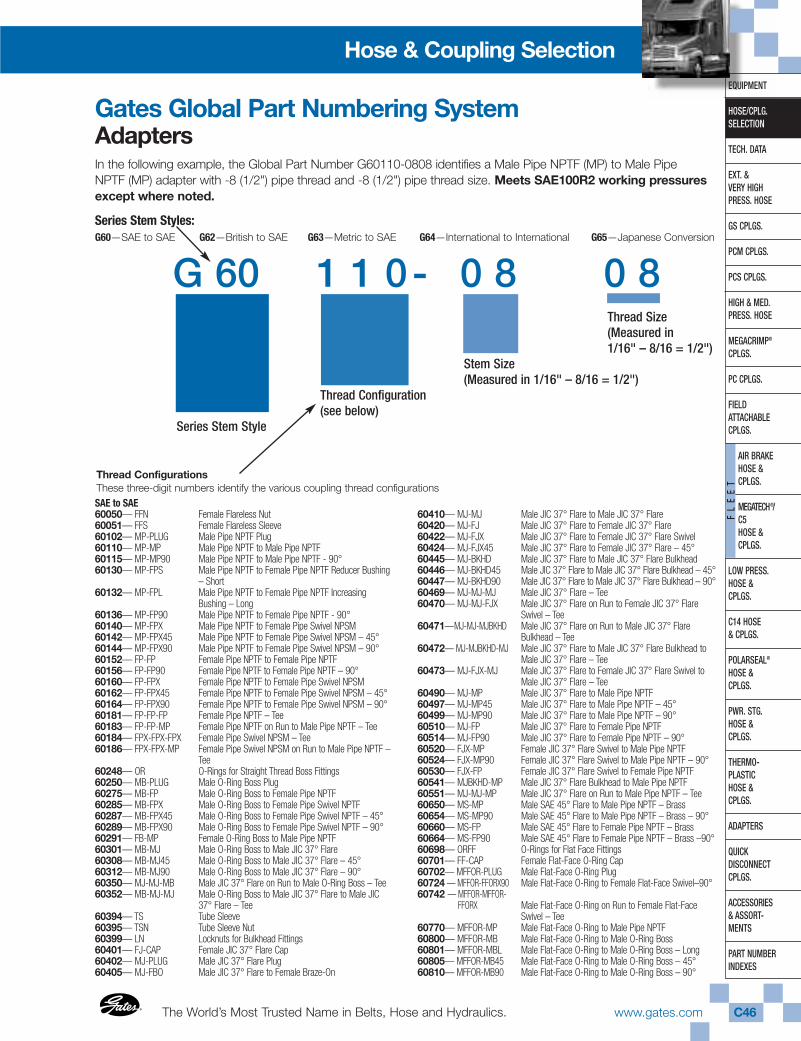
The World’s Most Trusted Name in Belts, Hose and Hydraulics.®
®
www.gates.com C46
EQUIPMENT
HOSE/CPLG.SELECTION
TECH. DATA
EXT. & VERY HIGHPRESS. HOSE
GS CPLGS.
PCM CPLGS.
PCS CPLGS.
HIGH & MED.PRESS. HOSE
MEGACRIMP®
CPLGS.
PC CPLGS.
FIELD ATTACHABLECPLGS.
AIR BRAKEHOSE & CPLGS.
MEGATECH®/ C5HOSE & CPLGS.
LOW PRESS.HOSE & CPLGS.
C14 HOSE& CPLGS.
POLARSEAL®
HOSE & CPLGS.
PWR. STG.HOSE & CPLGS.
THERMO-PLASTICHOSE & CPLGS.
ADAPTERS
QUICK DISCONNECTCPLGS.
ACCESSORIES& ASSORT-MENTS
PART NUMBERINDEXES
FL
EE
T
Hose & Coupling Selection
Gates Global Part Numbering SystemAdapters In the following example, the Global Part Number G60110-0808 identifies a Male Pipe NPTF (MP) to Male PipeNPTF (MP) adapter with -8 (1/2") pipe thread and -8 (1/2") pipe thread size. Meets SAE100R2 working pressuresexcept where noted.
G 60 1 1 0- 0 8 0 8
Series Stem Styles:G60—SAE to SAE G62—British to SAE G63—Metric to SAE G64—International to International G65—Japanese Conversion
SAE to SAE60050— FFN Female Flareless Nut60051— FFS Female Flareless Sleeve60102— MP-PLUG Male Pipe NPTF Plug60110— MP-MP Male Pipe NPTF to Male Pipe NPTF60115— MP-MP90 Male Pipe NPTF to Male Pipe NPTF - 90°60130— MP-FPS Male Pipe NPTF to Female Pipe NPTF Reducer Bushing
– Short60132— MP-FPL Male Pipe NPTF to Female Pipe NPTF Increasing
Bushing – Long60136— MP-FP90 Male Pipe NPTF to Female Pipe NPTF - 90°60140— MP-FPX Male Pipe NPTF to Female Pipe Swivel NPSM 60142— MP-FPX45 Male Pipe NPTF to Female Pipe Swivel NPSM – 45°60144— MP-FPX90 Male Pipe NPTF to Female Pipe Swivel NPSM – 90°60152— FP-FP Female Pipe NPTF to Female Pipe NPTF60156— FP-FP90 Female Pipe NPTF to Female Pipe NPTF – 90°60160— FP-FPX Female Pipe NPTF to Female Pipe Swivel NPSM60162— FP-FPX45 Female Pipe NPTF to Female Pipe Swivel NPSM – 45°60164— FP-FPX90 Female Pipe NPTF to Female Pipe Swivel NPSM – 90°60181— FP-FP-FP Female Pipe NPTF – Tee60183— FP-FP-MP Female Pipe NPTF on Run to Male Pipe NPTF – Tee60184— FPX-FPX-FPX Female Pipe Swivel NPSM – Tee60186— FPX-FPX-MP Female Pipe Swivel NPSM on Run to Male Pipe NPTF –
Tee60248— OR O-Rings for Straight Thread Boss Fittings60250— MB-PLUG Male O-Ring Boss Plug60275— MB-FP Male O-Ring Boss to Female Pipe NPTF60285— MB-FPX Male O-Ring Boss to Female Pipe Swivel NPTF60287— MB-FPX45 Male O-Ring Boss to Female Pipe Swivel NPTF – 45°60289— MB-FPX90 Male O-Ring Boss to Female Pipe Swivel NPTF – 90°60291— FB-MP Female O-Ring Boss to Male Pipe NPTF60301— MB-MJ Male O-Ring Boss to Male JIC 37° Flare60308— MB-MJ45 Male O-Ring Boss to Male JIC 37° Flare – 45°60312— MB-MJ90 Male O-Ring Boss to Male JIC 37° Flare – 90°60350— MJ-MJ-MB Male JIC 37° Flare on Run to Male O-Ring Boss – Tee 60352— MB-MJ-MJ Male O-Ring Boss to Male JIC 37° Flare to Male JIC
37° Flare – Tee 60394— TS Tube Sleeve60395— TSN Tube Sleeve Nut60399— LN Locknuts for Bulkhead Fittings60401— FJ-CAP Female JIC 37° Flare Cap60402— MJ-PLUG Male JIC 37° Flare Plug60405— MJ-FBO Male JIC 37° Flare to Female Braze-On
60410— MJ-MJ Male JIC 37° Flare to Male JIC 37° Flare60420— MJ-FJ Male JIC 37° Flare to Female JIC 37° Flare60422— MJ-FJX Male JIC 37° Flare to Female JIC 37° Flare Swivel60424— MJ-FJX45 Male JIC 37° Flare to Female JIC 37° Flare – 45°60445— MJ-BKHD Male JIC 37° Flare to Male JIC 37° Flare Bulkhead60446— MJ-BKHD45 Male JIC 37° Flare to Male JIC 37° Flare Bulkhead – 45°60447— MJ-BKHD90 Male JIC 37° Flare to Male JIC 37° Flare Bulkhead – 90°60469— MJ-MJ-MJ Male JIC 37° Flare – Tee60470— MJ-MJ-FJX Male JIC 37° Flare on Run to Female JIC 37° Flare
Swivel – Tee60471—MJ-MJ-MJBKHD Male JIC 37° Flare on Run to Male JIC 37° Flare
Bulkhead – Tee60472— MJ-MJBKHD-MJ Male JIC 37° Flare to Male JIC 37° Flare Bulkhead to
Male JIC 37° Flare – Tee60473— MJ-FJX-MJ Male JIC 37° Flare to Female JIC 37° Flare Swivel to
Male JIC 37° Flare – Tee60490— MJ-MP Male JIC 37° Flare to Male Pipe NPTF60497— MJ-MP45 Male JIC 37° Flare to Male Pipe NPTF – 45°60499— MJ-MP90 Male JIC 37° Flare to Male Pipe NPTF – 90°60510— MJ-FP Male JIC 37° Flare to Female Pipe NPTF60514— MJ-FP90 Male JIC 37° Flare to Female Pipe NPTF – 90°60520— FJX-MP Female JIC 37° Flare Swivel to Male Pipe NPTF60524— FJX-MP90 Female JIC 37° Flare Swivel to Male Pipe NPTF – 90°60530— FJX-FP Female JIC 37° Flare Swivel to Female Pipe NPTF60541— MJBKHD-MP Male JIC 37° Flare Bulkhead to Male Pipe NPTF60551— MJ-MJ-MP Male JIC 37° Flare on Run to Male Pipe NPTF – Tee60650— MS-MP Male SAE 45° Flare to Male Pipe NPTF – Brass60654— MS-MP90 Male SAE 45° Flare to Male Pipe NPTF – Brass – 90°60660— MS-FP Male SAE 45° Flare to Female Pipe NPTF – Brass60664— MS-FP90 Male SAE 45° Flare to Female Pipe NPTF – Brass –90°60698— ORFF O-Rings for Flat Face Fittings60701— FF-CAP Female Flat-Face O-Ring Cap60702— MFFOR-PLUG Male Flat-Face O-Ring Plug60724 — MFFOR-FFORX90 Male Flat-Face O-Ring to Female Flat-Face Swivel–90°60742 — MFFOR-MFFOR-
FFORX Male Flat-Face O-Ring on Run to Female Flat-FaceSwivel – Tee
60770— MFFOR-MP Male Flat-Face O-Ring to Male Pipe NPTF60800— MFFOR-MB Male Flat-Face O-Ring to Male O-Ring Boss60801— MFFOR-MBL Male Flat-Face O-Ring to Male O-Ring Boss – Long60805— MFFOR-MB45 Male Flat-Face O-Ring to Male O-Ring Boss – 45°60810— MFFOR-MB90 Male Flat-Face O-Ring to Male O-Ring Boss – 90°
Thread Size (Measured in1/16" – 8/16 = 1/2")
Stem Size (Measured in 1/16" – 8/16 = 1/2")
Thread Configuration (see below)
Series Stem Style
Thread ConfigurationsThese three-digit numbers identify the various coupling thread configurations
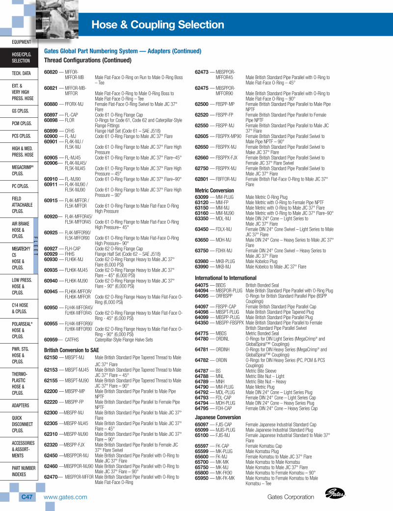
Gates CorporationC47 www.gates.com ®
®
EQUIPMENT
HOSE/CPLG.SELECTION
TECH. DATA
EXT. & VERY HIGHPRESS. HOSE
GS CPLGS.
PCM CPLGS.
PCS CPLGS.
HIGH & MED.PRESS. HOSE
MEGACRIMP®
CPLGS.
PC CPLGS.
FIELD ATTACHABLECPLGS.
AIR BRAKEHOSE &CPLGS.
MEGATECH®/C5HOSE &CPLGS.
LOW PRESS.HOSE & CPLGS.
C14 HOSE& CPLGS.
POLARSEAL®
HOSE & CPLGS.
PWR. STG.HOSE & CPLGS.
THERMO-PLASTICHOSE & CPLGS.
ADAPTERS
QUICK DISCONNECTCPLGS.
ACCESSORIES& ASSORT-MENTS
PART NUMBERINDEXES
FL
EE
T
Hose & Coupling Selection
60820 — MFFOR-MFFOR-MB Male Flat-Face O-Ring on Run to Male O-Ring Boss
– Tee 60821 — MFFOR-MB-
MFFOR Male Flat-Face O-Ring to Male O-Ring Boss toMale Flat-Face O-Ring – Tee
60880 — FFORX-MJ Female Flat-Face O-Ring Swivel to Male JIC 37°Flare
60897 — FL-CAP Code 61 O-Ring Flange Cap60898 — FLOR O-Rings for Code 61, Code 62 and Caterpillar-Style
Flange Fittings60899 — CFHS Flange Half Set (Code 61 – SAE J518)60900 — FL-MJ Code 61 O-Ring Flange to Male JIC 37° Flare60901 — FL4K-MJ /
FL5K-MJ Code 61 O-Ring Flange to Male JIC 37° Flare HighPressure
60905 — FL-MJ45 Code 61 O-Ring Flange to Male JIC 37° Flare–45°60906— FL4K-MJ45/
FL5K-MJ45 Code 61 O-Ring Flange to Male JIC 37° Flare HighPressure – 45°
60910 — FL-MJ90 Code 61 O-Ring Flange to Male JIC 37° Flare–90°60911 — FL4K-MJ90 /
FL5K-MJ90 Code 61 O-Ring Flange to Male JIC 37° Flare HighPressure – 90°
60915 — FL4K-MFFOR /FL5K-MFFOR Code 61 O-Ring Flange to Male Flat-Face O-Ring
High Pressure60920— FL4K-MFFOR45/
FL5K-MFFOR45 Code 61 O-Ring Flange to Male Flat-Face O-RingHigh Pressure– 45°
60925 — FL4K-MFFOR90/FL5K-MFFOR90 Code 61 O-Ring Flange to Male Flat-Face O-Ring
High Pressure– 90°60927 — FLH-CAP Code 62 O-Ring Flange Cap60929 — FHHS Flange Half Set (Code 62 – SAE J518)60930 — FLH6K-MJ Code 62 O-Ring Flange Heavy to Male JIC 37°
Flare (6,000 PSI)60935 — FLH6K-MJ45 Code 62 O-Ring Flange Heavy to Male JIC 37°
Flare – 45° (6,000 PSI)60940 — FLH6K-MJ90 Code 62 O-Ring Flange Heavy to Male JIC 37°
Flare - 90° (6,000 PSI)60945 — FLH6K-MFFOR/
FLH6K-MFFOR Code 62 O-Ring Flange Heavy to Male Flat-Face O-Ring (6,000 PSI)
60950 — FLH4K-MFFOR45/FLH6K-MFFOR45 Code 62 O-Ring Flange Heavy to Male Flat-Face O-
Ring - 45° (6,000 PSI)60955 — FLH4K-MFFOR90/
FLH6K-MFFOR90 Code 62 O-Ring Flange Heavy to Male Flat-Face O-Ring - 90° (6,000 PSI)
60959— CATFHS Caterpillar-Style Flange Halve Sets
British Conversion to SAE62150 — MBSPT-MJ Male British Standard Pipe Tapered Thread to Male
JIC 37° Flare62153 — MBSPT-MJ45 Male British Standard Pipe Tapered Thread to Male
JIC 37° Flare – 45°62155 — MBSPT-MJ90 Male British Standard Pipe Tapered Thread to Male
JIC 37° Flare – 90°62200 — MBSPP-MP Male British Standard Pipe Parallel to Male Pipe
NPTF62220 — MBSPP-FP Male British Standard Pipe Parallel to Female Pipe
NPTF62300 —MBSPP-MJ Male British Standard Pipe Parallel to Male JIC 37°
Flare62305 —MBSPP-MJ45 Male British Standard Pipe Parallel to Male JIC 37°
Flare – 45°62310 —MBSPP-MJ90 Male British Standard Pipe Parallel to Male JIC 37°
Flare – 90°62320 —MBSPP-FJX Male British Standard Pipe Parallel to Female JIC
37° Flare Swivel62450 —MBSPPOR-MJ Male British Standard Pipe Parallel with O-Ring to
Male JIC 37° Flare62460 —MBSPPOR-MJ90 Male British Standard Pipe Parallel with O-Ring to
Male JIC 37° Flare – 90°62470— MBSPPOR-MFFOR Male British Standard Pipe Parallel with O-Ring to
Male Flat-Face O-Ring
62473 — MBSPPOR-MFFOR45 Male British Standard Pipe Parallel with O-Ring to
Male Flat-Face O-Ring – 45°62475 — MBSPPOR-
MFFOR90 Male British Standard Pipe Parallel with O-Ring toMale Flat-Face O-Ring – 90°
62500 — FBSPP-MP Female British Standard Pipe Parallel to Male PipeNPTF
62520 — FBSPP-FP Female British Standard Pipe Parallel to FemalePipe NPTF
62550 — FBSPP-MJ Female British Standard Pipe Parallel to Male JIC37° Flare
62605 — FBSPPX-MP90 Female British Standard Pipe Parallel Swivel toMale Pipe NPTF – 90°
62650 — FBSPPX-MJ Female British Standard Pipe Parallel Swivel toMake JIC 37° Flare
62660 — FBSPPX-FJX Female British Standard Pipe Parallel Swivel toFemale JIC 37° Flare Swivel
62750 — FBSPPX-MJ Female British Standard Pipe Parallel Swivel toMale JIC 37° Flare
62801 — FBFFOR-MJ Female British Flat-Face O-Ring to Male JIC 37°Flare
Metric Conversion63099 — MM-PLUG Male Metric O-Ring Plug63120 — MM-FP Male Metric with O-Ring to Female Pipe NPTF63150 — MM-MJ Male Metric with O-Ring to Male JIC 37° Flare63160 — MM-MJ90 Male Metric with O-Ring to Male JIC 37° Flare–90°63350 — MDL-MJ Male DIN 24° Cone – Light Series to
Male JIC 37° Flare63450 — FDLX-MJ Female DIN 24° Cone Swivel – Light Series to Male
JIC 37° Flare63650 — MDH-MJ Male DIN 24° Cone – Heavy Series to Male JIC 37°
Flare63750 — FDHX-MJ Female DIN 24° Cone Swivel – Heavy Series to
Male JIC 37° Flare63980 — MKB-PLUG Male Kobelco Plug63990 — MKB-MJ Male Kobelco to Male JIC 37° Flare
International to International64075 — BBDS British Bonded Seal64094 — MBSPOR-PLUG Male British Standard Pipe Parallel with O-Ring Plug64095 — ORFBSPP O-Rings for British Standard Parallel Pipe (BSPP
Couplings)64097 — FBSPP-CAP Female British Standard Pipe Parallel Cap64098 — MBSPT-PLUG Male British Standard Pipe Tapered Plug64099 — MBSPP-PLUG Male British Standard Pipe Parallel Plug64350 — MBSPP-FBSPPX Male British Standard Pipe Parallel to Female
British Standard Pipe Parallel Swivel64775 — MBDS Metric Bonded Seal64780 — ORDINL O-Rings for DIN Light Series (MegaCrimp® and
GlobalSpiral™ Couplings)64781 — ORDINH O-Rings for DIN Heavy Series (MegaCrimp® and
GlobalSpiral™ Couplings)64782 — ORDIN O-Rings for DIN Heavy Series (PC, PCM & PCS
Couplings)64787 — BS Metric Bite Sleeve64788 — MNL Metric Bite Nut – Light64789 — MNH Metric Bite Nut – Heavy64790 — MM-PLUG Male Metric Plug64792 — MDL-PLUG Male DIN 24° Cone – Light Series Plug64793 — FDL-CAP Female DIN 24° Cone – Light Series Cap64794 — MDH-PLUG Male DIN 24° Cone – Heavy Series Plug64795 — FDH-CAP Female DIN 24° Cone – Heavy Series Cap
Japanese Conversion65097 — FJIS-CAP Female Japanese Industrial Standard Cap65099 — MJIS-PLUG Male Japanese Industrial Standard Plug65100 — FJIS-MJ Female Japanese Industrial Standard to Male 37°
Flare65597 — FK-CAP Female Komatsu Cap65599 — MK-PLUG Male Komatsu Plug65600 — FK-MJ Female Komatsu to Male JIC 37° Flare65700 — MK-MK Male Komatsu to Male Komatsu65750 — MK-MJ Male Komatsu to Male JIC 37° Flare65800 — MK-FK90 Male Komatsu to Female Komatsu – 90°65950 — MK-FK-MK Male Komatsu to Female Komatsu to Male
Komatsu – Tee
Gates Global Part Numbering System — Adapters (Continued)Thread Configurations (Continued)
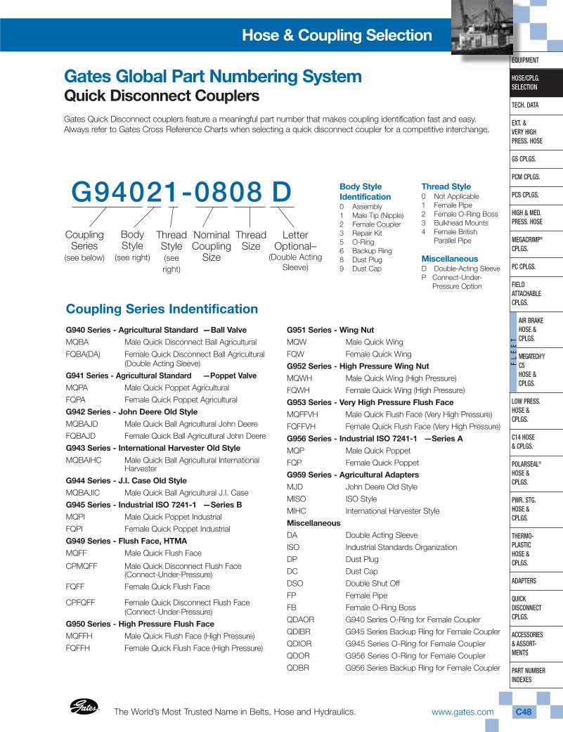
The World’s Most Trusted Name in Belts, Hose and Hydraulics.®
®
www.gates.com C48
EQUIPMENT
HOSE/CPLG.SELECTION
TECH. DATA
EXT. & VERY HIGHPRESS. HOSE
GS CPLGS.
PCM CPLGS.
PCS CPLGS.
HIGH & MED.PRESS. HOSE
MEGACRIMP®
CPLGS.
PC CPLGS.
FIELD ATTACHABLECPLGS.
AIR BRAKEHOSE & CPLGS.
MEGATECH®/ C5HOSE & CPLGS.
LOW PRESS.HOSE & CPLGS.
C14 HOSE& CPLGS.
POLARSEAL®
HOSE & CPLGS.
PWR. STG.HOSE & CPLGS.
THERMO-PLASTICHOSE & CPLGS.
ADAPTERS
QUICK DISCONNECTCPLGS.
ACCESSORIES& ASSORT-MENTS
PART NUMBERINDEXES
FL
EE
T
Hose & Coupling Selection
G94021-0808 DCoupling
Series(see below)
BodyStyle
(see right)
NominalCoupling
Size
ThreadSize
Gates Global Part Numbering SystemQuick Disconnect Couplers
Coupling Series Indentification
Gates Quick Disconnect couplers feature a meaningful part number that makes coupling identification fast and easy.Always refer to Gates Cross Reference Charts when selecting a quick disconnect coupler for a competitive interchange.
ThreadStyle(seeright)
LetterOptional–
(Double ActingSleeve)
G940 Series - Agricultural Standard —Ball ValveMQBA Male Quick Disconnect Ball Agricultural
FQBA(DA) Female Quick Disconnect Ball Agricultural(Double Acting Sleeve)
G941 Series - Agricultural Standard —Poppet ValveMQPA Male Quick Poppet Agricultural
FQPA Female Quick Poppet Agricultural
G942 Series - John Deere Old StyleMQBAJD Male Quick Ball Agricultural John Deere
FQBAJD Female Quick Ball Agricultural John Deere
G943 Series - International Harvester Old Style
MQBAIHC Male Quick Ball Agricultural InternationalHarvester
G944 Series - J.I. Case Old StyleMQBAJIC Male Quick Ball Agricultural J.I. Case
G945 Series - Industrial ISO 7241-1 —Series BMQPI Male Quick Poppet Industrial
FQPI Female Quick Poppet Industrial
G949 Series - Flush Face, HTMAMQFF Male Quick Flush Face
CPMQFF Male Quick Disconnect Flush Face (Connect-Under-Pressure)
FQFF Female Quick Flush Face
CPFQFF Female Quick Disconnect Flush Face (Connect-Under-Pressure)
G950 Series - High Pressure Flush FaceMQFFH Male Quick Flush Face (High Pressure)
FQFFH Female Quick Flush Face (High Pressure)
G951 Series - Wing NutMQW Male Quick Wing
FQW Female Quick Wing
G952 Series - High Pressure Wing NutMQWH Male Quick Wing (High Pressure)
FQWH Female Quick Wing (High Pressure)
G953 Series - Very High Pressure Flush FaceMQFFVH Male Quick Flush Face (Very High Pressure)
FQFFVH Female Quick Flush Face (Very High Pressure)
G956 Series - Industrial ISO 7241-1 —Series AMQP Male Quick Poppet
FQP Female Quick Poppet
G959 Series - Agricultural AdaptersMJD John Deere Old Style
MISO ISO Style
MIHC International Harvester Style
MiscellaneousDA Double Acting Sleeve
ISO Industrial Standards Organization
DP Dust Plug
DC Dust Cap
DSO Double Shut Off
FP Female Pipe
FB Female O-Ring Boss
QDAOR G940 Series O-Ring for Female Coupler
QDIBR G945 Series Backup Ring for Female Coupler
QDIOR G945 Series O-Ring for Female Coupler
QDOR G956 Series O-Ring for Female Coupler
QDBR G956 Series Backup Ring for Female Coupler
Body StyleIdentification0 Assembly1 Male Tip (Nipple)2 Female Coupler3 Repair Kit5 O-Ring6 Backup Ring8 Dust Plug9 Dust Cap
Thread Style0 Not Applicable1 Female Pipe2 Female O-Ring Boss3 Bulkhead Mounts4 Female British
Parallel Pipe
MiscellaneousD Double-Acting SleeveP Connect-Under-
Pressure Option
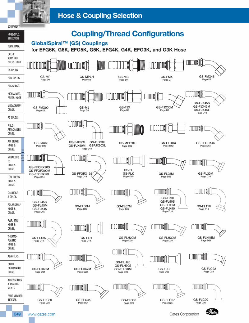
Gates CorporationC49 www.gates.com ®
®
EQUIPMENT
HOSE/CPLG.SELECTION
TECH. DATA
EXT. & VERY HIGHPRESS. HOSE
GS CPLGS.
PCM CPLGS.
PCS CPLGS.
HIGH & MED.PRESS. HOSE
MEGACRIMP®
CPLGS.
PC CPLGS.
FIELD ATTACHABLECPLGS.
AIR BRAKEHOSE &CPLGS.
MEGATECH®/C5HOSE &CPLGS.
LOW PRESS.HOSE & CPLGS.
C14 HOSE& CPLGS.
POLARSEAL®
HOSE & CPLGS.
PWR. STG.HOSE & CPLGS.
THERMO-PLASTICHOSE & CPLGS.
ADAPTERS
QUICK DISCONNECTCPLGS.
ACCESSORIES& ASSORT-MENTS
PART NUMBERINDEXES
FL
EE
T
Hose & Coupling Selection
GS-FJX90S GS-FJX90M
GS-FJX90L GSFJX90XL
GS-MFFORPage D12
GS-FFORXPage D12
GS-FFORX45Page D13
GS-FFORX90S GS-FFORX90MGS-FFORX90L
Page D14GS-FFORX135
Page D14GS-FL22M
Page D15GS-FL30M
Page D16
GS-FL45S GS-FL45MGS-FLK45
Page D16
GS-FL60MPage D17
GS-FL67MPage D17
GS-FL90GS-FL90SGS-FL90MGS-FLK90
Page D18
GS-FLHPage D19
GS-FLH22MPage D20
GS-FLH30MPage D20
GS-FLH45MPage D21
GS-FLH60MPage D21
GS-FLH67MPage D22
GS-FJX60Page D10
GS-FL135Page D19
GS-MPPage D6
GS-MPLHPage D6
GS-MBPage D7
GS-FMXPage D7
GS-FMX45Page D7
GS-FMX90Page D8
GS-MJPage D8
GS-FJXPage D9
GS-FJX30MPage D9
GS-FJX45SGS-FJX45MGS-FJX45L
Page D10
GlobalSpiral™ (GS) Couplings for EFG6K, G6K, EFG5K, G5K, EFG4K, G4K, EFG3K, and G3K Hose
GS-FL110Page D19
GS-FLH90 GS-FLH90S GS-FLH90M
Page D22GS-FLCPage D23
GS-FLC22Page D23
GS-FLC30Page D24
GS-FLC45Page D24
GS-FLC60Page D25
GS-FLC67Page D25
GS-FLC90Page D26
GS-FLGS-FLKPage D15
Page D11
Coupling/Thread Configurations
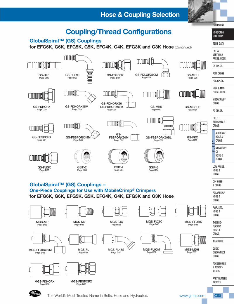
The World’s Most Trusted Name in Belts, Hose and Hydraulics.®
®
www.gates.com C50
EQUIPMENT
HOSE/CPLG.SELECTION
TECH. DATA
EXT. & VERY HIGHPRESS. HOSE
GS CPLGS.
PCM CPLGS.
PCS CPLGS.
HIGH & MED.PRESS. HOSE
MEGACRIMP®
CPLGS.
PC CPLGS.
FIELD ATTACHABLECPLGS.
AIR BRAKEHOSE & CPLGS.
MEGATECH®/ C5HOSE & CPLGS.
LOW PRESS.HOSE & CPLGS.
C14 HOSE& CPLGS.
POLARSEAL®
HOSE & CPLGS.
PWR. STG.HOSE & CPLGS.
THERMO-PLASTICHOSE & CPLGS.
ADAPTERS
QUICK DISCONNECTCPLGS.
ACCESSORIES& ASSORT-MENTS
PART NUMBERINDEXES
FL
EE
T
Hose & Coupling Selection
GS-FDLORXPage D27
GS-HLEPage D26
Coupling/Thread Configurations
GS-FDLORX90MPage D28
GS-MDHPage D28
GS-FDHORX45MPage D29
GS-FDHORX90GS-FDHORX90M
Page D30GS-MKBPage D30
GS-MBSPPPage D31
GS-FBSPORXPage D31
GS-FBSPORX45MPage D31
GS-FKXPage D33
GSIF-4Page D34
GSIF-6Page D34
GlobalSpiral™ (GS) Couplings for EFG6K, G6K, EFG5K, G5K, EFG4K, G4K, EFG3K and G3K Hose (Continued)
GS-FDHORXPage D29
GS-FBSPORX90M
Page D32GS-FBSPORX90BL
Page D32
GS-FJISXPage D33
GSIF-2Page D34
GlobalSpiral™ (GS) Couplings –One-Piece Couplings for Use with MobileCrimp® Crimpersfor EFG6K, G6K, EFG5K, G5K, EFG4K, G4K, EFG3K and G3K Hose
MGS-MPPage D35
MGS-MJPage D35
MGS-FJXPage D35
MGS-FFORXPage D36
MGS-FFORX90MPage D36
MGS-FJX90Page D35
MGS-FLPage D36
MGS-FL45SPage D37
MGS-FL90MPage D37
MGS-MDHPage D37
MGS-FDHORXPage D38
MGS-FBSPORXPage D38
GS-HLE90Page D27
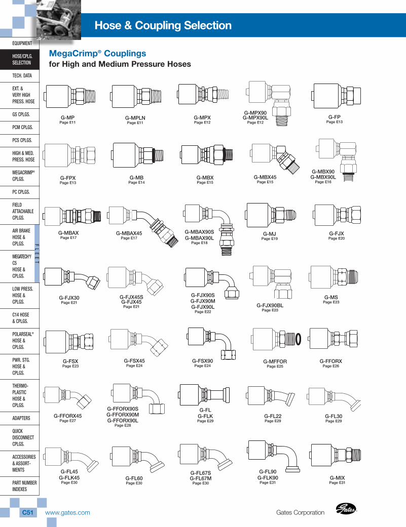
Gates CorporationC51 www.gates.com ®
®
EQUIPMENT
HOSE/CPLG.SELECTION
TECH. DATA
EXT. & VERY HIGHPRESS. HOSE
GS CPLGS.
PCM CPLGS.
PCS CPLGS.
HIGH & MED.PRESS. HOSE
MEGACRIMP®
CPLGS.
PC CPLGS.
FIELD ATTACHABLECPLGS.
AIR BRAKEHOSE &CPLGS.
MEGATECH®/C5HOSE &CPLGS.
LOW PRESS.HOSE & CPLGS.
C14 HOSE& CPLGS.
POLARSEAL®
HOSE & CPLGS.
PWR. STG.HOSE & CPLGS.
THERMO-PLASTICHOSE & CPLGS.
ADAPTERS
QUICK DISCONNECTCPLGS.
ACCESSORIES& ASSORT-MENTS
PART NUMBERINDEXES
FL
EE
T
Hose & Coupling Selection
G-FLG-FLKPage E29
G-FL22Page E29
G-FL30Page E29
G-FL90G-FLK90
Page E31G-MIXPage E31
G-FL67SG-FL67M
Page E30
G-FFORX45Page E27
G-FFORX90SG-FFORX90M G-FFORX90L
Page E28
G-FL45G-FLK45
Page E30G-FL60Page E30
G-MPPage E11
G-MPLNPage E11
G-MPXPage E12
G-MPX90G-MPX90L
Page E12G-FP
Page E13
G-FPXPage E13
G-MBPage E14
G-MBXPage E15
G-MBX45Page E15
G-MBAXPage E17
G-MBX90G-MBX90L
Page E16
G-MJPage E19
G-FJXPage E20
G-FJX30Page E21
G-FJX45SG-FJX45Page E21
G-FJX90S G-FJX90MG-FJX90L
Page E22
G-MSPage E23
G-FJX90BLPage E23
G-FSXPage E23
G-FSX45Page E24
G-MFFORPage E25
G-FFORXPage E26
G-FSX90Page E24
G-MBAX90SG-MBAX90L
Page E18
MegaCrimp® Couplingsfor High and Medium Pressure Hoses
G-MBAX45Page E17
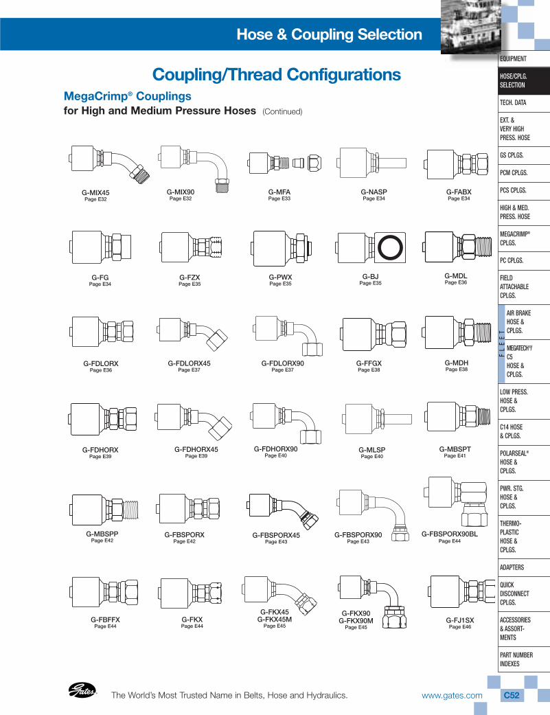
The World’s Most Trusted Name in Belts, Hose and Hydraulics.®
®
www.gates.com C52
EQUIPMENT
HOSE/CPLG.SELECTION
TECH. DATA
EXT. & VERY HIGHPRESS. HOSE
GS CPLGS.
PCM CPLGS.
PCS CPLGS.
HIGH & MED.PRESS. HOSE
MEGACRIMP®
CPLGS.
PC CPLGS.
FIELD ATTACHABLECPLGS.
AIR BRAKEHOSE & CPLGS.
MEGATECH®/ C5HOSE & CPLGS.
LOW PRESS.HOSE & CPLGS.
C14 HOSE& CPLGS.
POLARSEAL®
HOSE & CPLGS.
PWR. STG.HOSE & CPLGS.
THERMO-PLASTICHOSE & CPLGS.
ADAPTERS
QUICK DISCONNECTCPLGS.
ACCESSORIES& ASSORT-MENTS
PART NUMBERINDEXES
FL
EE
T
Hose & Coupling Selection
MegaCrimp® Couplingsfor High and Medium Pressure Hoses (Continued)
G-MIX45Page E32
G-MIX90Page E32
G-MFAPage E33
G-NASPPage E34
G-MDLPage E36
G-FDLORXPage E36
G-FDLORX45Page E37
G-FDLORX90Page E37
G-MDHPage E38
G-FDHORXPage E39
G-FDHORX45Page E39
G-FDHORX90Page E40
G-MLSPPage E40
G-MBSPPPage E42
G-FABXPage E34
G-FFGXPage E38
G-MBSPTPage E41
G-FBSPORXPage E42
G-FBSPORX45Page E43
G-FBSPORX90Page E43
G-FKXPage E44
G-FBSPORX90BLPage E44
G-FBFFXPage E44
G-FGPage E34
G-FZXPage E35
G-PWXPage E35
G-BJPage E35
G-FKX90G-FKX90M
Page E45G-FJ1SX
Page E46
Coupling/Thread Configurations
G-FKX45G-FKX45M
Page E45