gate valve control system series 64 - banner industries
TRANSCRIPT
x y
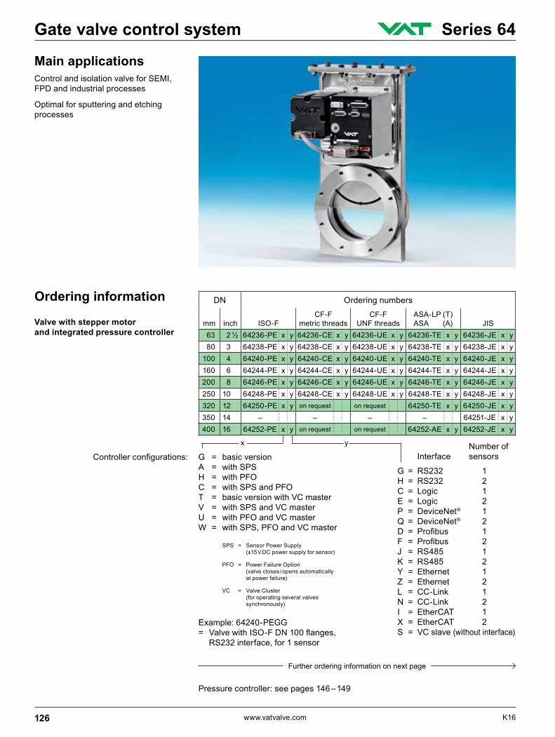
Ordering information
Valve with stepper motor and integrated pressure controller
Main applicationsControl and isolation valve for SEMI, FPD and industrial processes
Optimal for sputtering and etching processes
Example: 64240-PEGG= ValvewithISO-FDN100flanges,
RS232 interface, for 1 sensor
DN Ordering numbers
mm inch ISO-FCF-F
metric threadsCF-F
UNF threadsASA-LP (T) ASA (A) JIS
63 2 ½ 64236-PE x y 64236-CE x y 64236-UE x y 64236-TE x y 64236-JE x y 80 3 64238-PE x y 64238-CE x y 64238-UE x y 64238-TE x y 64238-JE x y 100 4 64240-PE x y 64240-CE x y 64240-UE x y 64240-TE x y 64240-JE x y 160 6 64244-PE x y 64244-CE x y 64244-UE x y 64244-TE x y 64244-JE x y 200 8 64246-PE x y 64246-CE x y 64246-UE x y 64246-TE x y 64246-JE x y 250 10 64248-PE x y 64248-CE x y 64248-UE x y 64248-TE x y 64248-JE x y 320 12 64250-PE x y on request on request 64250-TE x y 64250-JE x y 350 14 – – – – 64251-JE x y 400 16 64252-PE x y on request on request 64252-AE x y 64252-JE x y
Controllerconfigurations: G = basic versionA = with SPSH = with PFOC = with SPS and PFOT = basic version with VC masterV = with SPS and VC masterU = with PFO and VC masterW = with SPS, PFO and VC master
Number of Interface sensors
G = RS232 1H = RS232 2C = Logic 1E = Logic 2P = DeviceNet® 1Q = DeviceNet® 2D = Profibus 1F = Profibus 2J = RS485 1K = RS485 2Y = Ethernet 1Z = Ethernet 2L = CC-Link 1N = CC-Link 2I = EtherCAT 1X = EtherCAT 2S = VC slave (without interface)
SPS = Sensor Power Supply (±15 V DC power supply for sensor)
PFO = Power Failure Option (valve closes / opens automatically at power failure)
VC = Valve Cluster (for operating several valves synchronously)
Pressure controller: see pages 146 – 149
Further ordering information on next page
126 www.vatvalve.com K16
Gate valve control system Series 64
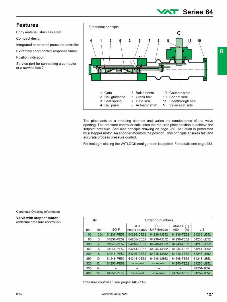
Functional principleFeaturesBody material: stainless steel
Compact design
Integrated or external pressure controller
Extremely short control response times
Position indication
Service port for connecting a computer or a service box 2
The plate acts as a throttling element and varies the conductance of the valve opening. The pressure controller calculates the required plate position to achieve the setpoint pressure. See also principle drawing on page 280. Actuation is performed by a stepper motor. An encoder monitors the position. This principle ensures fast and accurate process pressure control.
ForleaktightclosingtheVATLOCKconfigurationisapplied.Fordetailsseepage282.
1 Gate 5 Ball detents 9 Counter-plate 2 Ball guidance 6 Crank bolt 10 Bonnet seal 3 Leaf spring 7 Gate seal 11 Feedthrough seal4 Ball pairs 8 Actuator shaft Valve seat side
DN Ordering numbers
mm inch ISO-FCF-F
metric threadsCF-F
UNF threads ASA-LP (T) ASA (A) JIS
63 2 ½ 64236-PE52 64236-CE52 64236-UE52 64236-TE52 64236-JE52 80 3 64238-PE52 64238-CE52 64238-UE52 64238-TE52 64238-JE52 100 4 64240-PE52 64240-CE52 64240-UE52 64240-TE52 64240-JE52 160 6 64244-PE52 64244-CE52 64244-UE52 64244-TE52 64244-JE52 200 8 64246-PE52 64246-CE52 64246-UE52 64246-TE52 64246-JE52 250 10 64248-PE52 64248-CE52 64248-UE52 64248-TE52 64248-JE52 320 12 64250-PE52 on request on request 64250-TE52 64250-JE52 350 14 – – – – 64251-JE52 400 16 64252-PE52 on request on request 64252-AE52 64252-JE52
Continued Ordering information
Valve with stepper motor (external pressure controller)
Pressure controller: see pages 146 – 149
127K16 www.vatvalve.com
Series 64
B
DN
(n
omin
al I.
D.)
Standardflanges
Con
duct
ance
(molecularflow
)
Min
imum
con
trolla
ble
cond
ucta
nce
(molecularflow
)
Ope
ratin
g tim
e fo
r thr
ottli
ng
Typi
cal c
losi
ng o
r op
enin
g tim
e
Wei
ght
mm inch ls-1 ls-1 s s kg lbs 63 2 ½
See
pag
es 1
32 –
133
440 0.65 3 4 14 31 80 3 800 0.8 3 4 14 31 100 4 1 700 1 3 6 17 37 160 6 5 000 1.6 5 6 28 62 200 8 12 000 2 5 6 34 75 250 10 22 000 2.5 9 10 62 136 320 12 30 000 3.2 9 10 112 246 350 14 40 000 3.5 9 10 120 264 400 16 50 000 4 9 10 155 340
Leak rate 1): valve body, valve seat 1 · 10-9 mbar Is-1
Pressure range 1) – DN 63 – 200 1 · 10-8 mbar to 2.0 bar (abs) – DN 250 – 400 1 · 10-8 mbar to 1.2 bar (abs)
Differential pressure on the gate –Valveclosed DN 63–200 ≤2.0bar DN250–400 ≤1.2bar –Duringclosing/opening ≤30mbar
Cyclesuntilfirstservice 2) – Pressure control 1 million – Closing / opening 200 000
Temperature 2) –Valvebody ≤150°C –Ambient ≤ 50°C
Material – Valve body, plate AISI 304 (1.4301) – Mechanism AISI 301 (1.4310), AISI 304 (1.4301), AISI 420 (1.4034), AISI 420D (1.4037), AISI 430 (1.4016)
Seal: bonnet, gate, feedthrough FKM (Viton®)
Feedthrough rotary feedthrough
Mounting position – DN 63 – 350 any 3) – DN 400 horizontal only 4)
Valve position indication visual (mechanical and on controller)
Technical data
1) Unheated on delivery
2) Maximum values: depending on operating conditions and sealing materials
3) Seat side towards chamber
4) Vertical mounting position: see «Options»
– Seals on request (specify fabrication number of valve)
Spare parts
– Flange connections for installation of the valve: see series 32 and 33
Accessories
Technical data for pressure controller: see pages 146 – 149
128 www.vatvalve.com K16
Gate valve control system Series 64
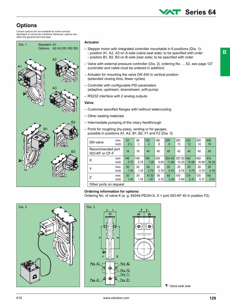
Actuator
– Stepper motor with integrated controller mountable in 6 positions (Dia. 1): -positionA1,A2,A3onA-side(valveseatside):tobespecifiedwithorder -positionB1,B2,B3onB-side(rearside):tobespecifiedwithorder
– Valve with external pressure controller (Dia. 2), ordering No. … 52, see page 127 (controller and cable must be ordered in addition)
– Actuator for mounting the valve DN 400 in vertical position (extended closing time, fewer cycles)
–ControllerwithconfigurablePIDparameters (adaptive, upstream, downstream, soft-pump)
– RS232 interface with 2 analog outputs
Valve
–Customerspecifiedflangeswith/withoutwatercooling
– Other sealing materials
– Intermediate pumping of the rotary feedthrough
– Ports for roughing (by-pass), venting or for gauges, possible in positions A1, A2, B1, B2, F1 and F2 (Dia. 3)
OptionsCertain options are not available for some nominal diameters or cannot be combined. Moreover, options can affect the general technical data.
Dia. 1
Dia. 2 Dia. 3
Ordering information for options:Ordering No. of valve-X (e. g. 64244-PEGH-X, X = port ISO-KF 40 in position F2)
DN valve mm inch
63 2 ½
80 3
100 4
160 6
200 8
250 10
320 12
350 14
400 16
Recommended port ISO-KF or CF-F 16 16 40 40 40 40 40 40 40
X mm inch
146 5.75
146 5.75
185 7.28
245 9.65
304.40 11.98
387.30 15.25
482 18.98
482 18.98
415 16.34
Y mm inch
30 1.18
30 1.18
20 0.79
20 0.79
20 0.79
20 0.79
20 0.79
20 0.79
20 0.79
Z mm inch
30 1.18
30 1.18
47.50 1.87
59 2.32
85 3.35
100 3.94
135 5.31
135 5.31
140 5.51
Other ports on request
Standard: A1 Options: A2 / A3 / B1 / B2 / B3
Valve seat side
129K16 www.vatvalve.com
Series 64
B
DN mm inch
63 2 ½
80 3
100 4
160 6
200 8
250 10
320 12
350 14
400 16
J mm inch
134 5.28
134 5.28
172 6.77
222 8.74
274 10.79
355 13.98
420 16.54
420 16.54
474 18.66
K mm inch
73 2.87
73 2.87
93 3.66
123 4.84
148 5.83
177 6.97
214 8.43
214 8.43
232 9.13
L mm inch
208 8.19
208 8.19
267 10.51
361 14.21
438 17.24
570 22.44
688 27.09
688 27.09
787 30.98
M mm inch
250 9.84
250 9.84
228 8.98
154 6.06
213 8.39
298 11.73
393 15.47
393 15.47
479 18.86
N mm inch
144 5.67
144 5.67
144 5.67
144 5.67
144 5.67
144 5.67
144 5.67
144 5.67
144 5.67
O mm inch
180 7.09
180 7.09
220 8.66
300 11.81
350 13.78
450 17.72
550 21.65
550 21.65
600 23.62
P mm inch
94 3.70
94 3.70
132 5.20
192 7.56
252 9.92
320 12.60
415 16.34
415 16.34
501 19.72
Q mm inch
105 4.13
105 4.13
105 4.13
105 4.13
105 4.13
134 5.28
134 5.28
134 5.28
134 5.28
R mm inch
98 3.86
98 3.86
98 3.86
98 3.86
98 3.86
134 5.28
134 5.28
134 5.28
134 5.28
S mm inch
105 4.13
105 4.13
105 4.13
105 4.13
105 4.13
105 4.13
105 4.13
105 4.13
105 4.13
T mm inch
79 3.11
79 3.11
96 3.78
108 4.25
134 5.28
167 6.57
202 7.95
202 7.95
207 8.15
U mm inch
129 5.08
129 5.08
112 4.41
100 3.94
74 2.91
77 3.03
42 1.65
42 1.65
36 1.42
V mm inch
212 8.35
212 8.35
212 8.35
252 9.92
304 11.97
400 15.75
475 18.70
475 18.70
520 20.47
W mm inch
51 2.01
51 2.01
63 2.48
75 2.95
75 2.95
97 3.82
120 4.72
120 4.72
130 5.12
X mm inch
80 3.15
80 3.15
80 3.15
100 3.94
100 3.94
138 5.43
138 5.43
138 5.43
138 5.43
Y mm inch
180 7.09
180 7.09
180 7.09
186 7.32
186 7.32
221 8.70
221 8.70
221 8.70
226 8.90
Z mm inch
100 3.94
100 3.94
100 3.94
100 3.94
100 3.94
100 3.94
100 3.94
100 3.94
100 3.94
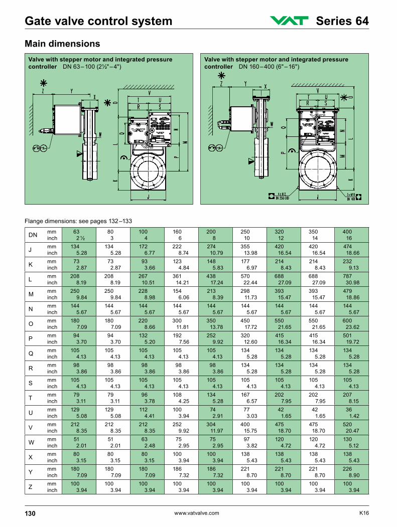
Main dimensionsValve with stepper motor and integrated pressure controller DN 160 – 400 (6" – 16")
Valve with stepper motor and integrated pressure controller DN 63 – 100 (2½" – 4")
Flange dimensions: see pages 132 –133
130 www.vatvalve.com K16
Gate valve control system Series 64

Projection E
DN mm inch
63 2 ½
80 3
100 4
160 6
200 8
250 10
320 12
350 14
400 16
J mm inch
134 5.28
134 5.28
172 6.77
222 8.74
274 10.79
355 13.98
420 16.54
420 16.54
474 18.66
K mm inch
73 2.87
73 2.87
93 3.66
123 4.84
148 5.83
177 6.97
214 8.43
214 8.43
232 9.13
L mm inch
208 8.19
208 8.19
267 10.51
361 14.21
438 17.24
570 22.44
688 27.09
688 27.09
787 30.98
O mm inch
180 7.09
180 7.09
220 8.66
300 11.81
350 13.78
450 17.72
550 21.65
550 21.65
600 23.62
P mm inch
94 3.70
94 3.70
132 5.20
192 7.56
252 9.92
320 12.60
415 16.34
415 16.34
501 19.72
Q mm inch
105 4.13
105 4.13
105 4.13
105 4.13
105 4.13
134 5.28
134 5.28
134 5.28
134 5.28
R mm inch
98 3.86
98 3.86
98 3.86
98 3.86
98 3.86
134 5.28
134 5.28
134 5.28
134 5.28
T mm inch
79 3.11
79 3.11
96 3.78
108 4.25
134 5.28
167 6.57
202 7.95
202 7.95
207 8.15
V mm inch
212 8.35
212 8.35
212 8.35
252 9.92
304 11.97
400 15.75
475 18.70
475 18.70
520 20.47
W mm inch
51 2.01
51 2.01
63 2.48
75 2.95
75 2.95
97 3.82
120 4.72
120 4.72
130 5.12
X mm inch
80 3.15
80 3.15
80 3.15
100 3.94
100 3.94
138 5.43
138 5.43
138 5.43
138 5.43
Y mm inch
180 7.09
180 7.09
180 7.09
186 7.32
186 7.32
221 8.70
221 8.70
221 8.70
226 8.90
Z mm inch
100 3.94
100 3.94
100 3.94
100 3.94
100 3.94
100 3.94
100 3.94
100 3.94
100 3.94
Main dimensionsValve with stepper motor (external pressure controller) DN 63 – 400 (2½" – 16")
Valve seat side g Required for dismantlingc Electrical connectionf Position indicatore Mechanical position indicationi For attachment
Flange dimensions: see pages 132 –133
131K16 www.vatvalve.com
Series 64
B

Projection E
ISO-F DN 63 – 320 (2½" – 12")
DN mm inch
63 2.½
80 3
100 4
160 6
200 8
250 10
320 12
A mm inch
70 2.76
70 2.76
70 2.76
70 2.76
80 3.15
100 3.94
120 4.72
B mm inch
130 5.12
145 5.71
165 6.50
225 8.86
285 11.22
350 13.78
425 16.73
C mm inch
110 4.33
125 4.92
145 5.71
200 7.87
260 10.24
310 12.20
395 15.55
D mm inch
70 2.76
76 2.99
100 3.94
150 5.91
200 7.87
261 10.28
306 12.05
E × F 4 × M8 8 × M8 8 × M8 8 × M10 12 × M10 12 × M10 12 × M12
G mm inch
13 0.51
13 0.51
13 0.51
15 0.59
15 0.59
15 0.59
18 0.71
H mm inch – 83
3.27 102 4.02
153 6.02
213 8.39 – 318
12.52
I mm inch – 3
0.12 3 0.12
5 0.20
5 0.20 – 5
0.20
DN mm inch
63 2 ½
80 3
100 4
160 6
200 8
250 10
O. D. inch 4 ½ 4⅝ 6 8 10 12
A mm inch
70 2.76
70 2.76
70 2.76
70 2.76
80 3.15
100 3.94
B mm inch
113.50 4.47
117.50 4.63
151.60 5.97
202.40 7.97
253.20 9.97
350 13.78
C mm inch
92.10 3.63
102.40 4.03
130.20 5.13
181 7.13
231.80 9.13
284 11.18
D mm inch
70 2.76
76 2.99
100 3.94
150 5.91
200 7.87
254 10
E × F 8 × M8 10 × M8 16 × M8 20 × M8 24 × M8 32 × M8
H1 mm inch
82.50 3.25
91.65 3.61
120.70 4.75
171.45 6.75
222.40 8.76
273.15 10.75
H2 mm inch
77.40 3.05
86.30 3.40
115.50 4.55
166 6.54
217 8.54
267 10.51
DN mm inch
63 2 ½
80 3
100 4
160 6
200 8
250 *) 10
250 *) 10
O. D. inch 4 ½ 4⅝ 6 8 10 12 13 ¼
A mm inch
70 2.76
70 2.76
70 2.76
70 2.76
80 3.15
100 3.94
100 3.94
B mm inch
113.50 4.47
117.50 4.63
151.60 5.97
202.40 7.97
253.20 9.97
350 13.78
350 13.78
C mm inch
92.10 3.63
102.40 4.03
130.20 5.13
181 7.13
231.80 9.13
284 11.18
306.30 12.06
D mm inch
70 2.76
76 2.99
100 3.94
150 5.91
200 7.87
254 10
254 10
E × F 8 × 5/16" 24 UNF
10 × 5/16" 24 UNF
16 × 5/16" 24 UNF
20 × 5/16" 24 UNF
24 × 5/16" 24 UNF
32 × 5/16" 24 UNF
30 × 3/8" 24 UNF
H1 mm inch
82.50 3.25
91.65 3.61
120.70 4.75
171.45 6.75
222.40 8.76
273.15 10.75
294.64 11.60
H2 mm inch
77.40 3.05
86.30 3.40
115.50 4.55
166 6.54
217 8.54
267 10.51
288.30 11.35
Flange dimensions
Valve seat side
CF-F, metric threads DN 63 – 250 (2½" – 10")
CF-F, UNF threads DN 63 – 250 (2½" – 10")
*) O. D. 12" VAT standard, O. D. 13¼" option
Ordering information for option: O. D. 13¼" Ordering No. of valve-X (e. g. 64248-UE . . -X, X = O. D. 13¼")
DN 400 (16"): see series 14.0, page 71
132 www.vatvalve.com K16
Gate valve control system Series 64

JIS B 2290: 1998 / ISO 1609 DN 65 – 300 (2½" – 12")
Projection E
DN mm inch
65 2 ½
80 3
100 4
150 6
200 8
250 10
300 12
A mm inch
70 2.76
70 2.76
70 2.76
70 2.76
80 3.15
100 3.94
120 4.72
B mm inch
136 5.35
165 6.50
185 7.28
235 9.25
300 11.81
350 13.78
425 16.73
C mm inch
120 4.72
135 5.31
160 6.30
210 8.27
270 10.63
320 12.60
370 14.57
D mm inch
70 2.76
76 2.99
100 3.94
150 5.91
200 7.87
261 10.28
306 12.05
E × F 4 × M10 8 × M10 8 × M10 8 × M10 8 × M12 12 × M12 12 × M12
G mm inch
12 0.47
12 0.47
12 0.47
12 0.47
15 0.59
15 0.59
16. 0.63
Flange dimensions
Valve seat side
ASA-LP DN 63 – 320 (2½" – 12")with or without O-ring groove
For orders with O-ring groove specify:«A», «B» or «A + B»
DN mm inch
63 2 ½
80 3
100 4
160 6
200 8
250 10
320 12
ASA-LP 2 – 3 4 6 8 10
A mm inch
70 2.76
70 2.76
70 2.76
70 2.76
80 3.15
100 3.94
120 4.72
B mm inch
152.40 6
177.80 7
190.50 7.50
225 8.86
279.40 11
350 13.78
425 16.73
C mm inch
120.70 4.75
139.70 5.50
152.40 6
190.50 7.50
241.30 9.50
298.50 11.75
362 14.25
D mm inch
70 2.76
76 2.99
100 3.94
150 5.91
200 7.87
254 10
300 11.81
E × F 4 × ⅜" 16 UNC
4 × ⅜" 16 UNC
4 × ⅜“ 16 UNC
8 × ⅜" 16 UNC
8 × ¾" 10 UNC
8 × ¾" 10 UNC
12 × ¾" 10 UNC
G mm inch
15 0.59
15 0.59
15 0.59
15 0.59
19 0.75
19 0.75
19 0.75
H mm inch
88.90 3.50
88.90 3.50
120.65 4.75
158.75 6.25
206.40 8.13
266.70 10.50
317.50 12.50
O-ring I. D. × d
mm inch
88.49 × 3.53 3.48 × .139
88.49 × 3.53 3.48 × .139
120.24 × 3.53 4.73 × .139
158.34 × 3.53 6.23 × .139
202.79 × 3.53 7.98 × .139
266.29 × 3.53 10.48 × .139
316.87 × 7.00 12.47 × .275
DN 400 (16"): see series 14.0, page 71
DN 400 (16"): see series 14.0, page 71
133K16 www.vatvalve.com
Series 64
B
Function
Electrical connections
Accessories
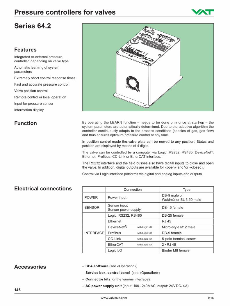
FeaturesIntegrated or external pressure controller, depending on valve type
Automatic learning of system parameters
Extremely short control response times
Fast and accurate pressure control
Valve position control
Remote control or local operation
Input for pressure sensor
Information display
By operating the LEARN function – needs to be done only once at start-up – the system parameters are automatically determined. Due to the adaptive algorithm the controller continuously adapts to the process conditions (species of gas, gas flow) and thus ensures optimum pressure control at any time.
In position control mode the valve plate can be moved to any position. Status and position are displayed by means of 4 digits.
The valve can be controlled by a computer via Logic, RS232, RS485, DeviceNet®, Ethernet, Profibus, CC‑Link or EtherCAT interface.
The RS232 interface and the field busses also have digital inputs to close and open the valve. In addition, digital outputs are available for «open» and / or «closed».
Control via Logic interface performs via digital and analog inputs and outputs.
Connection Type
POWER Power input DB-9 male or Weidmüller SL 3.50 male
SENSOR Sensor input Sensor power supply DB-15 female
INTERFACE
Logic, RS232, RS485 DB-25 female
Ethernet RJ 45
DeviceNet® with Logic I/O Micro-style M12 male
Profibus with Logic I/O DB-9 female
CC‑Link with Logic I/O 5‑pole terminal screw
EtherCAT with Logic I/O 2 × RJ 45
Logic I/O Binder M8 female
– CPA software (see «Operation»)
– Service box, control panel (see «Operation»)
– Connector kits for the various interfaces
– AC power supply unit (input: 100 – 240 V AC, output: 24 V DC / 4 A)
Series 64.2
146
www.vatvalve.com K16
Pressure controllers for valves
Operation
Options
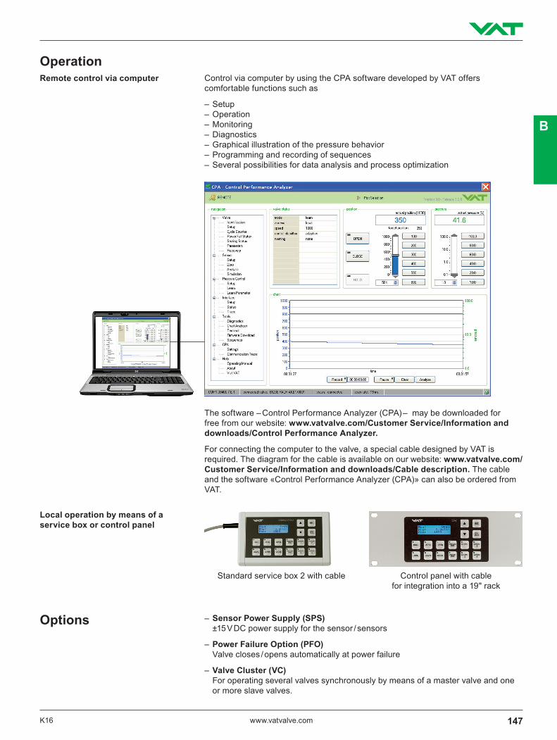
Standard service box 2 with cable Control panel with cable for integration into a 19" rack
Control via computer by using the CPA software developed by VAT offers comfortable functions such as
– Setup – Operation – Monitoring – Diagnostics – Graphical illustration of the pressure behavior – Programming and recording of sequences – Several possibilities for data analysis and process optimization
Remote control via computer
Local operation by means of a service box or control panel
The software – Control Performance Analyzer (CPA) – may be downloaded for free from our website: www.vatvalve.com/Customer Service/Information and downloads/Control Performance Analyzer.
For connecting the computer to the valve, a special cable designed by VAT is required. The diagram for the cable is available on our website: www.vatvalve.com/ Customer Service/Information and downloads/Cable description. The cable and the software «Control Performance Analyzer (CPA)» can also be ordered from VAT.
– Sensor Power Supply (SPS) ±15 V DC power supply for the sensor / sensors
– Power Failure Option (PFO) Valve closes / opens automatically at power failure
– Valve Cluster (VC) For operating several valves synchronously by means of a master valve and one or more slave valves.
147K16 www.vatvalve.com
B

126 (4.96)
168
(6.6
1)
157
(6.1
8)
105 (4.13)80 (3.15)
Ø 5
.5 (
0.22
)
Integrated controller: Series 64.2 External controller: (for series 64.2 and 65.2 available as an option)
Available interfaces:– Logic– RS232– RS485– DeviceNet®
– Ethernet– Profibus– CC‑Link– EtherCAT
Power consumption max. +24 V DC (±10 %) @ 0.5 V pk‑pk – Controller + motor max. 55 W (S62, 64.2), max. 100 W (S67) – Power failure option (PFO) max. 10 W – Sensor power supply (SPS) max. 36 W
Sensor supply 24 V DC or ±15 V DC
Sensor input – Signal voltage 0 – 10 V DC linear with pressure – Input resistance Ri = 100 kΩ – Resolution 0.23 mV – Sampling rate 10 ms
Control accuracy 5 mV or 0.1% of setpoint 1)
Position resolution depending on valve type
Protective system IP 20 1) The higher value applies
Example: RS232
148 www.vatvalve.com K16
Pressure controllers for valves