gast roa raa series oilless vacuum pump
DESCRIPTION
Gast ROA RAA Series Oilless Vacuum Pump operation manual and parts diagram for ROA-P101-AA, ROA-P101-BN, ROA-P101-JH, ROA-P112-EB, ROA-V110-AA, ROA-V110-BN, RAA-V110-EB, RAA-V110-ED, RAA-V11-EB, RAA-P125-EEGTRANSCRIPT
~GAST.70-5300 G481 PL (Rev.B)
ROAJRAA SERIES OILLESSVACUUM PUMPS & COMPRESSORS
,OPERATION & MAINTENANCETECHNICAL MANUAL
CONTENTS:General Information, Installation .and Wiring.
2
Operation, Maintenance Inspection, 3and Shut-Down Procedures.
ROASeries Exploded View and . .4Parts Ordering Information.
RAA Series Exploded View and..... . 5Parts Ordering Information.
Troubleshooting, Warranty, and 6Authorized Service Facilities.
IKEEP THIS DOCUMENT FOR FUTURE REFERENCEI
e, CAUTION Remove the plastic plugs in the intake and exhaust ports beforeoperating unit.
Refer to the wiring tag supplied with the unit, fordiagram and capacitor options. For any DC unit red lead goes to positive side of power source.
PLUMBINGTo prevent air flow restriction, use pipe and fittingsthat are the same size or larger than the threadedports of the pump. NOTE: Be sure to connect theintake and exhaust plumbing to the correct inlet andoutlet ports.
ACCESSORIESFilters and mufflers are supplied on some models.Check periodically and replace when necessary.Consult a Gast Representative for filter recommendations. For best results, install relief valves andgauges at the inlet or outlet, or both, to monitorperformance.
Solid or liquid material exiting theunit can cause eye or skin damage.Keep away from air stream.
Incorrect wiring can result in electricshock. Wiring must conform to allrequired safety codes and beinstalled by a qualified person.Grounding is required for all ACmodels. All power to the motor mustbe de-energized and disconnectedwhen servicing.Metal capacitor shell must contact agrounded surface. Electrical shockcan result from touching ungroundedcapacitor.
OPERATIONe,WARNING
e, WARNING
WIRINGe, WARNING
ELECTRIC MOTOR CONTROLThe motor must be protected against short circuit,overload and excessive temperature rise. Fuses,motor protective switches and thermal protectiveswitches provide the necessary protection in thesecircumstances. Fuses only serve as a short circuitprotection of the motor (wiring fault). Fuses in theincoming line should be chosen so as to be able towithstand the starting current of the motor, not as aprotection against overload. Motor starters, incorporating thermal magnetic overload or circuit breakersprotect the motor from overload or reduced voltageconditions. Selection of the correct overload settingis required to provide the best possible protection.Refer to the motor starter manufacturer's recommendations.MOUNTING THE PUMP
The pump may be installed in any orientation as longas the flow of cool, ambient air over the pump is notblocked. To reduce noise and vibration, use shockmounts and aflix to a stable, rigid operating surface.
GENERAL INFORMATIONThis pump is designed to be used for the purpose ofpumping air. The pump should not be used for thepumping of fluids, particles, solids or any combustiblesubstances likely to cause explosions.e, DANGER Do not pump flammable or explosive
gases or operate the unit in an atmosphere containing them.
e, CAUTION The pump is designed for pumping air.Do not allow corrosive gases orparticulate material to enter the pump.Water, oil-based contaminants, orother liquids must be filtered out.
e, CAUTION Normal ambient temperature shouldnot exceed 40° C (104° F). Foroperation at higher temperatures,consult the factory.
e, WARNING Exhaust air temperature can become very hot. Keep away from airstream.
Performance is reduced by low atmospheric pressurefound at high altitudes. Consult a Gast distributor fordetails.
Never lubricate this oil-less pump. Most componentsare made of aluminum and the valves are stainlesssteel.
The following is an explanation of the three differenttypes of hazards:
e, DANGER Severe personal injury or deathwill occur if hazard is ignored.
e, WARNING Severe personal injury or deathcan occur if hazard is ignored.
e, CAUTION Minor injury or property damagecan occur if hazard is ignored.
INSTALLATIONe, WARNING To avoid risk of electrocution do not
use this product in an area where itcould come in contact with water orother liquids. If exposed to the elements, it must be weather protected.
e, CAUTION Do not block the flow of cooling airover the pump in any way.
This is the hazard alert symbol: e. When you seethis symbol, be aware that personal injury or propertydamage is possible. The hazard is explained in thetext following the symbol. Read the informationcarefully before proceeding.
2

&WARNING
&WARNING
& WARNING
& CAUTION
STARTING& CAUTION
Always disconnect the power beforeservicing. The motor may be thermallyprotected and will restart automaticallywhen it cools if the thermal protectionswitch is tripped.Do not operate without the grille(s), ifprovided, in place. Failure to do socould result in severe personal injury.The head surface(s) can be very hotdepending on pump duty and speed.Do not touch these parts duringoperation.Do not operate units above recommended pressures or vacuum duties.To do so will damage the unit.
Do not start against a vacuum orpressure load.
2. After using the pump, disconnect plumbing andallow the pump to run 'open" for at least 5 minutesbefore shutdown.3. Plug the open ports to prevent dirt or othercontaminents from entering the pump. It is now readyfor shutdown or storage.
SERVICE KIT INSTALLATION
PUMP DISASSEMBLY:1. Disconnect the pump from the electrical power.&WARNING You must disconnect the pump from
electrical power before servicing it.Failure to do so can result in severepersonal injury or death
2. Vent all air lines to the pump to remove pressure.&WARNING You must vent all air lines to the pump
to remove pressure before servicing it.Failure to do so can result in severepersonal injury.
If the pump is extremely cold, let it warm up to roomtemperature before starting. If the pump does notoperate properly, see the troubleshooting guide.NOTE: Some of these models may exceed 70 dB(A).When in close proximity to these models hearingprotection is required. Refer to the Technical DataSheet for your specific model.
MAINTENANCE AND INSPECTIONIntake filter and mufflers require periodic inspection andreplacement. Initial inspection is suggested at 500hours, then the user should determine the frequencythereafter. Most problems can be prevented by keeping filters and mufflers clean. Dirty filters and mufflersdecrease pump performance and can decrease pumplife.
FILTER INSPECTION AND REPLACEMENTThe head surface(s) on some models can be very hotduring operation. Do not touch these parts until thepump has been turned off and allowed to cool. Somefilter element(s) are held together by a snap fit. Remove the cover to replace the felt, and reassemble.
SHUTDOWN PROCEDURESProper shutdown procedures must be followed to .prevent pump damage. Failure to do so may result Inpremature pump failure. The Gast Manufactunng nonlubricated 'Jacuum pumps and compressors areconstructed of ferrous metals or aluminum which aresubject to rust and corrosion when pumping condensable vapors such as water.Follow the steps below to assure correct storage andshutdown between use:
1. NEVER oil this non-lubricated pump.
NOTE: Gast will not guarantee the performance of afield rebuilt pump. You can return the pump to a Gastauthorized facility, or perform the rebuild proceduresdescribed below:
'Remove the head bolts and remove head.'Remove valve plate and install new valves.'Clean all residue from valve seats being careful not toscratch the surface.'Remove the cylinder and two phillips screws on theretainer plate.'Remove shims under the cylinder (NOTE: Be sure toreplace all the shims as they are matched to thecylinder and rod assembly height dimensions).'Remove cup from retainer plate and install new cup.'Torque screws to 30 inch-pounds.'Place shims under cylinder and install cylinder overcup (NOTE: For ease of installation do not bringcylinder directly down on cup).'Insert a-Ring in groove in cylinder.'Replace Head Gasket.'Install Valve Plate on the Head by aligning the smallhole in Valve Plate with the locating pin on the Head.'Install Head and Valve Plate on cylinder so ports are intheir original orientation.'Insert Headbolts and torque to 90-100 in. Ibs.
NOTE: Before putting the pump into service, ensure that anyexternal accessories such as relief valves and gauges attached to
the head have not been damaged.
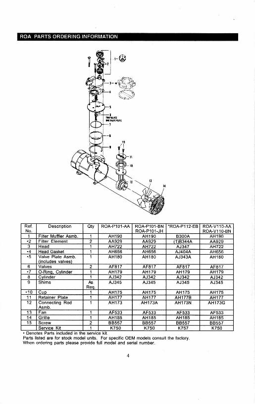
ROA PARTS ORDERING INFORMATION
Ref. Description Qty ROA-P101-AA ROA-P101-BN -ROA-P112-EB ROA-V110-AANo. ROA-P101-JH ROA-V110-BN1 Filter Muffler Asmb. 1 AH190 AH190 B300A AH190-2 Filter Element 2 AA929 AA929 (1lB344A AA9293 Head 1 AH722 AH722 AJ347 AH722-4 Head Gasket 1 AH656 AH656 AJ404A AH656-5 I ~alve Plate AS~b. 1 AH180 AH180 AJ343A AH180
includes valves6 Valves 2 AF817 AF817 AF817 AF817-7 O-Rina, CYlinder 1 AH179 AH179 AH179 AH1798 CYlinder 1 AJ342 AJ342 AJ342 AJ3429 Shims As AJ345 AJ345 AJ345 AJ345
Ren.-10 Cuo 1 AH175 AH175 AH175 AH17511 Retainer Plate 1 AH177 AH177 AH177B AH17712 Connecting Rod 1 AH173 AH173A AH173N AH173G
Asmb.13 Fan 1 AF533 AF533 AF533 AF53314 Grille 1 AH185 AH185 AH185 AH18515 Screw 2 BB557 BB557 BB557 BB557
Service Kit 1 K750 K750 K757 K750- Denotes Parts Included In the service kit.Parts listed are for stock model units. For specific OEM models consult the factory.When ordering parts please provide full model and serial number.
4
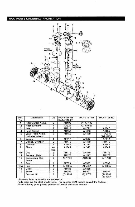
,RAA PARTS ORDERING INFORMATION
Ref, Description Qty RAA-V110-E8 RAA-V111-E8 'RAA-P125-EGNo, RAA-V110-ED1 Filter/Muffler Asmb, 2 AH190 (1) AH190'2 Filter Element 4 AA929 (2) AA9293 Head 2 AH722 AH722 AJ347'4 Head Gasket 2 AH656 AH656 AJ404'5 Valve Plate Asmb, 2 AH180 AH180 (1)AJ343
I (includes valves) 11\AJ343A6 Valves 4 AF817 AF817 AF817'7 O-Rino, Cvlinder 2 AH179 AH179 AH1798 Cvlinder 2 AJ342 AJ342 AJ3429 Shims As AJ345 AJ345 AJ345
Reo,·10 CuP 2 AH175 AH175 AH17511 Retainer Plate 2 AH177 AH177 AH17712 Connecting Rod 2 AH173H AH173J AH173H
Asmb,13 Fan 1 AF533 AF533 AF533
13A Fan 1 AF533A AF533A AF533A14 Grille 2 AH185 AH185 -15 Screw 4 88557 88557 88557
Service Kit 1 (2) K750 (2) K750 (1) K756(1) K757
• Denotes Parts Included In the service kit.Parts listed are for stock model units, For specific OEM models consult the f~ctory,
When ordering parts please provide full model and serial number,
5

TROUBLE SHOOTING GUIDELOW HIGH LOW EXCESSIVE OVER WON'T
REASON PRESSURE PRESSURE VACUUM NOISE HEATING START·Dirtv Filter x xDirtv Muffler x x' xDirtv Valves x xDamaaed Valves x x x xWornlDamaaed Cuo x xImproper Cylinder x x x x x xShimminaLeakv Hose x xLeakv Check Valve xPlugged Vac. or x x x x xPress. LineLow Voltaae x x x xLeaKv Relief Valve x x
YOUR WARRANTY
REGARDLESS OF CAUSE, if a product you buyfrom this catalog does not work right, Gast will repair orreplace it once, at no charge, for up to one year from thedate of shipment from the factory.In the course of repair or replacement, Gast may sendyou written recommendations on how to prevent aproblem from happening again. Gast reselVes the rightto withdraw this warranty ij you do not follow theserecommendations. Customer is responsible for freightcharges both to and from Gast in all caSes.This warranty does not apply to electric motors, electricalcontrols, and gasoline engines, which Gast obtains fromother manufacturers. A motor or engine carries only thewarranty of the company that makes it.
THIS WARRANlY is EXCLUSIVE AND IS IN LIEU OFALL OTHER WARRANTIES, WHETHER WRIDENORAL OR IMPLIED, INCLUDING THE WARRANTY OFMERCHANTABILITY AND OF FiTNESS FOR ANYPARTICULAR PURF'aSE. GASrS LIABILITY is IN ALLCASES LIMITED TO THE REPLACEMENT PRICE OFITS PRODUCT. GAST SHALL NOT BE LIABLE FORANY OTHER DAMAGES, WHETHERCONSEQUENTIAL, INDiRECT, OR INCIDENTAL,ARISING FROM THE SALE OR USE OF ITSPRODUCTS.
Gas!'s sales personnel may modify this warranty, but only bysigning a specific, written description of any modifications.
AUTHORIZED SERVICE FACILITIES
Gast Manufacturing Corp9970 Red Arrow HwyBridgman, MI 49106TEL: 616-926-6171FAX: 616-465-4300
Gast Manufacturing Corp505 Washington AveCarlstadt, NJ 07072TEL: 201-933-8484FAX: 201-933-5545
Brenner Fiedler & Assoc.13824 Bentley PlaceCerritos, CA 90701TEL: 800-843-5558TEL: 310-404-2721FAX: 310-404-7975
Gast Manufacturing Co., LtdBeech Hause, Knaves BeechBusiness Centre, LoudwaterHigh Wycombe, Bucks HP 10 9SDEnglandTEL: 44 628 532600FAX: 44 628 532470
Wainbee Limited215 Brunswick Blvd.Pointe Claire. QuebecCanada H9R 4R7TEL: 514-697-8810FAX: 514-697-3070
.Wainbee Limited5789 Coopers AvenueMississauga, OntarioCanada L4Z 3S6TEL: 416-213-7202FAX: 416-213-7207
Japan Machinery Co. Ltd.Central PO Box 1451Tokyo, 100-91 JapanTEL: 81-3-3573-5421FAX: 81-3-3571-7865
or: 81-3-3571-7896
NOTE: General Correspondenceshould be senl 10"Gasl ManulaCluring Corp.POBox97Benton Hart>or. Ml 49022.Q097