gasoline-electric hybrid synergy drive - crown motors vehicle... · toyota prius gasoline-electric...
TRANSCRIPT

Gasoline-Electric
Hybrid Synergy Drive
NHW20 Series

Foreword This guide was developed to educate and assist dismantlers in the safe handling of the
Toyota Prius gasoline-electric hybrid vehicle. Prius dismantling procedures are similar to
other Toyota vehicles with the exception of the high voltage electrical system. It is
important to recognize and understand the high voltage electrical system features and
specifications of the Toyota Prius as they may not be familiar to dismantlers.
High voltage electricity powers an electric motor, generator, electric inverter compressor
(for air conditioner) and inverter. All other conventional automotive electrical devices
such as the headlights, radio, and gauges are powered from a separate 12-Volt battery.
Numerous safeguards have been designed into the Prius to help ensure the high voltage,
approximately 201-Volts, Nickel Metal Hydride (NiMH) Hybrid Vehicle (HV) battery pack
is kept safe and secure in an accident.
The NiMH HV battery pack contains sealed batteries that are similar to rechargeable
batteries used in laptop computers, cell phones, and other consumer products. The
electrolyte is absorbed in the cell plates and will not normally leak out even if the battery is
cracked. In the unlikely event the electrolyte does leak, it can be easily neutralized with a
dilute boric acid solution or vinegar.
High voltage cables, identifiable by orange insulation and connectors, are isolated from the
metal chassis of the vehicle
Additional topics contained in the guide include:
• Toyota Prius identification.
• Major hybrid component locations and descriptions.
By following the information in this guide, dismantlers will be able to handle the Prius
hybrid-electric vehicle as safely as the dismantling of a conventional gasoline engine
automobile.
2004 Toyota Motor Corporation All rights reserved. This book may not be reproduced or copied, in whole or in part, without the written permission of Toyota Motor Corporation
ii
Table of Contents
ABOUT THE PRIUS ..................................................................................................................... 1
PRIUS IDENTIFICATION.............................................................................................................. 2 Exterior .........................................................................................................................................................3 Interior...........................................................................................................................................................4 Engine Compartment ....................................................................................................................................5
HYBRID COMPONENT LOCATIONS & DESCRIPTIONS .......................................................... 6 Specifications................................................................................................................................................6
GASOLINE-ELECTRIC HYBRID VEHICLE OPERATION........................................................... 8 Vehicle Operation..........................................................................................................................................8
HYBRID VEHICLE (HV) BATTERY PACK AND AUXILIARY BATTERY .................................... 9 HV Battery Pack............................................................................................................................................9 Components Powered by the HV Battery Pack.............................................................................................9 HV Battery Pack Recycling .........................................................................................................................10 Auxiliary Battery ..........................................................................................................................................10
HIGH VOLTAGE SAFETY .......................................................................................................... 11 High Voltage Safety System........................................................................................................................ 11 Service plug ................................................................................................................................................ 11
PRECAUTION TO BE OBSERVED WHEN DISMANTLING THE VEHICLE ............................ 13 Necessary items .........................................................................................................................................13
SPILLAGE................................................................................................................................... 14
DISMANTLING A VEHICLE ....................................................................................................... 15
REMOVAL OF HV BATTERY ..................................................................................................... 18 HV battery removal .....................................................................................................................................18 HV Battery Caution Label ...........................................................................................................................25
iii


About the prius The Toyota prius (NHW20 Series) is a gasoline-electric hybrid vehicle sold in the world since September 2003. Gasoline-electric hybrid means the vehicle contains a gasoline engine and an electric motor for power. Two energy sources are stored on-board the vehicle:
1. Gasoline stored in the fuel tank for the gasoline engine. 2. Electricity stored in a high voltage Hybrid Vehicle (HV) battery pack for the
electric motor. The result of combining these two power sources has increased fuel economy and reduced emissions. The gasoline engine also powers an electric generator to recharge the battery pack; so, unlike a pure all electric vehicle, the Prius never needs to be recharged from an external electric power source. Depending on the driving conditions, one or both sources are used to power the vehicle. The following illustrations demonstrate how the Prius operates in various driving modes.
On light acceleration at low speeds, the vehicle is powered by the electric motor. The gasoline engine is shut off.
During normal driving, the vehicle is powered mainly by the gasoline engine.
The gasoline engine is also used to recharge the battery pack. During full acceleration, such as climbing a hill, both the gasoline engine and the
electric motor power the vehicle.
During deceleration, such as braking, the vehicle regenerates the kinetic energy from the front wheels to produce electricity that recharges the battery pack.
While the vehicle is stopped, the gasoline engine and electric motor are off,
however the vehicle remains on and operational.
1
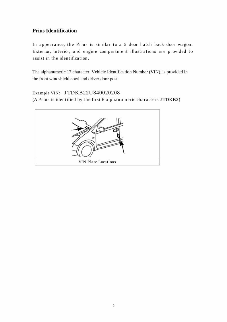
Prius Identification In appearance, the Prius is similar to a 5 door hatch back door wagon. Exterior, interior, and engine compartment illustrations are provided to assist in the identification. The alphanumeric 17 character, Vehicle Identification Number (VIN), is provided in the front windshield cowl and driver door post. Example VIN: JTDKB22U840020208 (A Prius is identified by the first 6 alphanumeric characters JTDKB2)
VIN Plate Locations
2
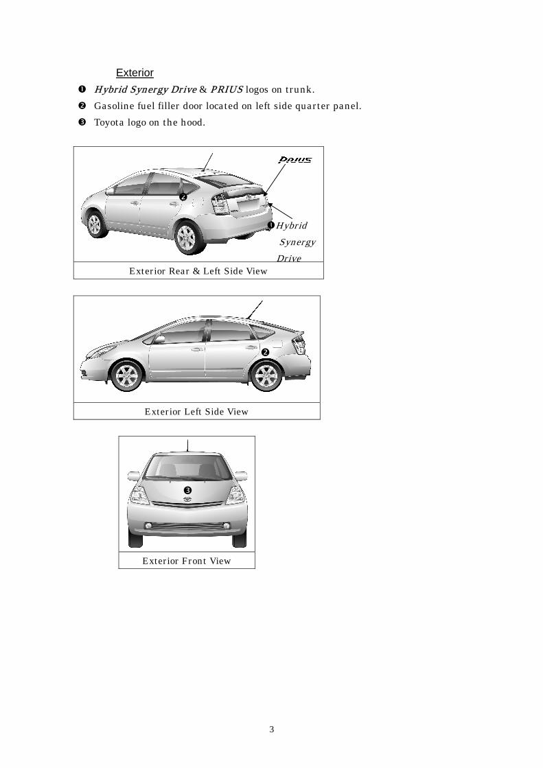
Exterior Hybrid Synergy Drive & PRIUS logos on trunk. Gasoline fuel filler door located on left side quarter panel. Toyota logo on the hood.
Exterior Rear & Left Side View
Exterior Left Side View
Exterior Front View
Hybrid Synergy
Drive
3

Prius Identification (Continued)
Interior Center cluster mounted automatic transmission shift selector lever. Instrument cluster (speedometer, fuel gauge and warning lights) located in the
dash and near the base of the windshield. LCD monitor (fuel consumption and radio controls) located below the
instrument cluster.
Interior View
Instrument Cluster & LCD Moni
tor
4

Engine Compartment 1.5 liter aluminum alloy gasoline engine. High voltage inverter with the Toyota Synergy Drive logo on the cover. Orange colored high voltage power cables.
Toyota Synergy Drive Logo on Inverter
En
gine Compartm
ent5

Hybrid Component Locations & Descriptions
Component Location Description
12-Volt Auxiliary
Battery
Luggage, RH Side Low voltage lead-acid battery that controls all
electrical equipment except electric motor generator
and inverter.
Hybrid Vehicle
(HV) Battery
Pack
Luggage, Mounted
to Cross Member &
Behind Rear Seat
201.6-Volts Nickel Metal Hydride (NiMH) battery pack
consisting of 28 low voltage (7.2-volts) modules
connected in series.
Power Cables
Under Carriage &
Engine
Compartment
Orange colored power cables carry high voltage
Direct Current (DC) between the HV battery pack and
inverter. Also carry 3 phase Alternating Current (AC)
between inverter, motor, and generator.
Inverter Engine
Compartment
Converts 200V DC electricity from HV battery pack
into 500V DC electricity that drives electric motor.
Also, converts AC from electric generator and motor
(regenerative braking) into DC that recharges HV
battery pack.
Gasoline
Engine
Engine
Compartment
Provides two functions: 1) powers vehicle; 2) powers
generator to recharge HV battery pack. Engine is
started and stopped under control of vehicle
computer.
Electric Motor
Engine
Compartment
3 Phase AC permanent magnetic electric motor
contained in transaxle. Used to power the vehicle.
Electric
Generator
Engine
Compartment
3 Phase AC generator contained in transaxle. Used to
recharge HV battery pack.
Fuel Tank
and Fuel Lines
Undercarriage, RH
Side
Fuel tank provides gasoline via a single fuel line to the
engine. The fuel line is routed along RH side under
the floor pan.
Specifications
Gasoline Engine: 1.5 liter Aluminum Alloy Engine
North America: 57KW (76hp). Europe , Australia and others: 57KW (77PS)
Electric Motor: 50 KW (68 PS), Permanent Magnet Motor
Transmission: Automatic Only
HV Battery: 201.6-Volts Sealed NiMH
Curb Weight: North America: 1,310 Kg (2890lbs), Europe: 1,300 kg, Australia: 1,295kg
Fuel Tank: 45 litters / 11.9 gals
Frame Material: Steel Unibody & Steel Body Panels and Aluminum engine food/back door
6

Section A-A Power Cable
Power Cables
7
12-Volt ⊕ Cable
12-Volt ⊕ Cable
Gasoline-Electric Hybrid Vehicle Operation The vehicle starts and becomes operational by inserting key into key-slot and pressing ‘POWER’ button while depressing brake pedal. However, the gasoline engine does not idle like a typical automobile and will start and stop automatically. It is important to understand the READY indicator provided in the instrument cluster. When the READY indicator is on, it informs the driver that the vehicle is ready to be driven even though the gasoline-powered engine is not running and the engine compartment is silent. Optional Smart Entry & Start system allows you to operate the “POWER” button without inserting the key into the key slot.
Vehicle Operation • With the Prius, the gasoline engine may stop and start at any time while the
READY indicator is on. • Never assume that the vehicle is shut off just because the engine is off.
Always check the READY indicator status. The vehicle is shut off when the READY indicator is off.
• The vehicle may be powered by: 1. The electric motor only. 2. The gasoline engine only. 3. A combination of both the electric motor and the gasoline engine.
The vehicle computer determines the mode in which the vehicle operates to improve fuel economy and reduce emissions. The driver cannot manually select the mode.
POWER button Instrument Cluster READY Indicator
8

Hybrid Vehicle (HV) Battery Pack and Auxiliary Battery The PRIUS contains a high voltage, Hybrid Vehicle (HV) battery pack and a low voltage auxiliary battery. The HV battery pack contains non-spillable, sealed Nickel Metal Hydride (NiMH) battery modules and the auxiliary battery is a typical automotive lead-acid type.
HV Battery Pack The HV battery pack is sealed in a metal case and is rigidly mounted on the luggage floor pan cross member behind the rear seat. The metal case is isolated from high voltage and concealed by a fabric liner in the luggage space.
•
•
•
•
The HV battery pack consists of 28 low voltage (7.2-Volts) NiMH battery modules connected in series to produce approximately 201.6-Volts. Each NiMH battery module is non-spillable and sealed in a plastic case.
The electrolyte used in the NiMH battery module is an alkaline of potassium and sodium hydroxide. The electrolyte is absorbed into the battery cell plates and forms a gel that does not normally leak, even in a collision.
In the unlikely event that the battery pack is overcharged, the modules vent gases directly out of the vehicle through a vent hose connected to each NiMH battery module.
HV Battery Pack
Battery pack voltage 201.6-Volts
Number of NiMH battery modules in the
pack
28
Battery pack weight 39Kg (86 lbs)
NiMH battery module voltage 7.2-Volts
NiMH battery module dimensions (inches) 276x20x106mm (11x1x4)
NiMH Battery module weight 1040g (2.3 lbs)
Components Powered by the HV Battery Pack
• Electric Motor • Inverter • Electric Generator • Power Cables • Electric Powered A/C Compressor
9

HV Battery Pack Recycling The HV battery pack is recyclable. Contact your Toyota Distributor as mentioned on HV battery Caution Label(see the page 25 to 27) or the nearest Toyota dealer.
•
Auxiliary Battery
The PRIUS also contains a lead-acid 12-Volt battery. This 12-Volt auxiliary battery powers the vehicle electrical systems similarly to a conventional vehicle. As with other conventional vehicles, the auxiliary battery is grounded to the metal chassis of the vehicle.
•
• The auxiliary battery is located in the luggage space. It also contains a hose to vent gases out of the vehicle if overcharged.
HV Battery Pack 12-Volt Auxiliary Battery
10

High Voltage Safety The HV battery pack powers the high voltage electrical system with direct current (DC) electricity. A positive and negative power cables are routed from the battery pack, under the vehicle floor pan, to the inverter. Occupants in the vehicle are separated from high voltage electricity by the following systems:
High Voltage Safety System • A high voltage fuse provides short circuit protection in the HV battery pack.
• The positive and negative power cables connected to the HV battery pack are controlled by 12-Volt normally open relays . When the vehicle is shut off, the relays stop electricity flow from the HV battery pack.
WARNING:
• Power remains in the high voltage electrical system for 5 minutes after the HV battery pa k is shut off. c
• Never touch, cut, or open any orange high voltage power cable or high voltage component.
• Both power cables are isolated from the metal chassis, so there is no possibility of shock
by touching the metal chassis.
• A ground fault monitor continuously monitors the metal chassis for high voltage
leakage while the vehicle is running. If a malfunction is detected, the vehicle computer will illuminate the master warning light in the instrument cluster and the hybrid warning
light in the LCD display.
• The HV battery pack relays will automatically open to stop electricity flow in a collision sufficient to active the front SRS airbags.
Service Plug The high-voltage circuit is cut by removing service plug (See page 15). •
11

High Voltage Safety System – Vehicle Shut Off (READY
201
High Voltage Safety System – Vehicle On and Operational (Ron)
12
off)
EADY

Precaution to be observed when dismantling the vehicle
WARNING:
・ Never assume that the Prius is shut off simply because it is silent. ・ Assure that READY indicator is off. ・ Remove the key from the key slot. ・ After removing the service plug, wait 5 minutes before touching any of the
high-voltage connectors and terminals.
・ Before dismantling the high-voltage system, take measures such as wearing insulated gloves and removing the service plug to prevent electrocution.
・ If either of the disabling steps above cannot be performed, proceed with caution as there is no assurance that the high voltage electrical system, SRS, or fuel pump are disabled.
・ Never touch, cut, or open any orange high voltage power cable or high voltage component.
Necessary items
Protective clothing (insulated gloves, rubber gloves, safety goggles, and safety shoes).
•
• •
Vinyl tape for insulation Before wearing insulated the vehicle gloves, make sure that they are not cracked, ruptured, torn, or damaged in any other way. Do not wear wet insulated gloves.
13

Spillage The Prius contains the same common automotive fluids used in other Toyota vehicles, with the exception of NiMH electrolyte used in HV battery pack. The NiMH battery electrolyte is a caustic alkaline (pH 13.5) that causes damage to human tissues. The electrolyte, however, is absorbed in the cell plates and will not normally spill or leak out even if a battery module is cracked. A catastrophic crash that would breach both the metal battery pack case and the plastic battery module would be a rare occurrence. Similar to using baking soda to neutralize a lead-acid battery electrolyte spillage, a dilute boric acid solution or vinegar is used to neutralize the NiMH battery electrolyte spillage. In an emergency, Toyota Material Safety Data Sheets (MSDS) may be requested.
• Handle NiMH Electrolyte Spills Using The Following Personal Protective Equipment (PPE):
Splash shield or safety goggles. Folding down helmet shields is not acceptable for alkaline spillage.
•
•
•
•
•
•
Rubber, latex or Nitrile gloves. Apron suitable for alkaline. Rubber boots.
• Neutralize NiMH Electrolyte Use a boric acid solution or vinegar.
Boric acid solution - 800 grams boric acid to 20 liters water or 5.5 ounces boric acid to 1 gallon of water.
14

Dismantling a vehicle
WARNING:
・ Never assume that the Prius is shut off simply because it is silent. ・ Assure that READY indicator is off. ・ Remove the key from the key slot. ・ After removing the service plug, wait 5 minutes before touching any of the
high-voltage connectors and terminals.
・ Before dismantling the high-voltage system, take measures such as wearing insulated gloves and removing the service plug to prevent electrocution.
・ If either of the disabling steps above cannot be performed, proceed with caution as there is no assurance that the high voltage electrical system, SRS, or fuel pump are disabled.
・ Never touch, cut, or open any orange high voltage power cable or high voltage component.
1 Remove the key from the key slot.
Then disconnect the negative (-) terminal of the auxiliary battery and remove the service plug.
a) Remove the deck floor box rear as shown in the illustration.
b) Slide up the lever of the service plug. Remove the service plug grip while turning the lever to the left.
Lever
c) Insulate the service plug socket with insulating tape.
15

2 Carry the removed service plug in your pocket to prevent other technicians from
reinstalling it while you are dismantling the vehicle. 3 Use the CAUTION: HIGH VOLTAGE. DO NOT TOUCH DURING
OPERATION sign to notify other technicians that a high-voltage system is being dismantled (see the page 17).
4. If the service plug cannot be removed due to damage to the rear portion of the vehicle, remove the HEV fuse (20A:Yellow) or power integration (IGCT relay) instead.
Power Integration
5 After disconnecting or exposing a
high-voltage connector or terminal, insulate it immediately using insulation tape. Before touching a bare high-voltage terminal, wear insulated gloves.
6. Check the HV battery and nearby area for leakage. If you find any liquid, it could be the leakage of the strong alkaline electrolyte. Wear rubber gloves and goggles and neutralize the liquid using the saturated boric acid solution or vinegar. Then wipe up the liquid using waste rags etc.
a) If the electrolyte adheres to your skin, wash the skin immediately using the saturated boric acid solution or a large amount of water. If the electrolyte adheres to an article of clothing, take it off immediately.
b) If the electrolyte comes into contact with your eyes, call out loudly for help. Do not rub your eyes but wash them with a dilute boric acid solution or a large amount of water and seek medical care.
7 Remove the parts by the procedures which are similar to the Toyota vehicles with exception of HV battery. As for the removal of HV battery, place refer to following pages.
16

17 17

Removal of HV battery
HV battery removal
WARNING:
・ Never assume that the Prius is shut off simply because it is silent. ・ Assure that READY indicator is off. ・ Remove the key from the key slot. ・ After removing the service plug, wait 5 minutes before touching any of the
high-voltage connectors and terminals.
・ Before dismantling the high-voltage system, take measures such as wearing insulated gloves and removing the service plug to prevent electrocution.
・ If either of the disabling steps above cannot be performed, proceed with caution as there is no assurance that the high voltage electrical system, SRS, or fuel pump are disabled.
・ Never touch, cut, or open any orange high voltage power cable or high voltage component.
LOCK LOCK
FREE FREE
1 Remove rear floor board No. 2. a) As shown in the
illustration, twist the knob and release the lock.
b) Remove the rear floor board No. 2
2 Remove deck floor box rear.
Remove the deck floor box rear as shown in the illustration.
18

3 Remove rear floor board No. 3.
Remove the rear floor board No. 3 as shown in the illustration.
4 Disconnect battery negative terminal.
Disconnect the negative terminal of the 12 V auxiliary battery.
5 Remove the key from the key slot.
Then disconnect the negative (-) terminal of the auxiliary battery and remove the service plug.
Lever
a) Slide up the lever of the service plug. Remove the service plug grip while turning the lever to the left.
b) Insulate the service plug socket with insulating tape.
Clip
6 Remove deck trim cover rear. Disconnect the 4 clips
shown in the illustration, then remove the deck trim cover rear.
19

Joint
7 Remove tonneau cover 8 Remove rear seat cushion
Undo the 2 joints shown in the illustration, then remove the rear seat cushion.
Clip
9 Remove rear floor board No. 1. a) Remove the 2 bolts and
luggage hold belt strikers. b) Remove the 5 clips shown
in the illustration and the rear floor board No. 1.
Joint
10 Remove rear side seat back frame LH. a) Remove the bolt from the
rear side seat back frame LH.
b) Undo the 3 joints, then remove the rear side seat back frame LH.
20

Clip
11 Remove deck floor box LH. Remove the clip and deck
floor box LH. 12 Remove deck trim side panel LH
Clip
a) Remove the bolt and luggage hold belt striker LH.
b) Remove the 2 bolts from the deck trim side panel LH.
c) Remove the clip from the deck trim side panel LH.
d) Undo the 8 clips, then pull out a part of the weather strip and remove the deck trim side panel LH.
e) Disconnect the lighting connector. 13 Remove deck trim side panel RH
C
a) Remove the bolt and luggage hold belt striker RH.
b) Remove the 2 bolts from the deck trim side panel RH.
c) Remove the clip from the deck trim side panel RH.
d) Undo the 7 clips, then pull out a part of the weather strip and remove the deck trim side panel RH.
21
lip

14 Remove battery carrier bracket
Remove the 7 bolts and battery carrier bracket.
15 Remove quarter vent duct inner No. 2.
a) Disconnect the clamp and battery blower relay No. 1.
b) Remove the 2 clips. c) Slide the ventilation inner
duct No. 2 to the battery side, then remove it.
16 Remove battery bracket reinforcement.
Remove the 7 bolts and battery bracket reinforcement.
17 Remove quarter vent duct.
a) Disconnect the connector. b) Remove the clamp, then
disconnect the wire harness.
c) Remove the bolt, clip and quarter ventilation duct.
22
Battery Blower Relay No. 1
Clamp Clip
Bolt

18 Remove battery carrier panel No. 6.
Remove the 3 bolts, 2 nuts and battery carrier panel No. 6.
19 Remove junction terminal. 20 Remove frame wire.
Remove the 2 nuts, then disconnect the frame wire from the system main relay No. 2 and No. 3.
Earth Bolt 21 Remove HV battery. a) Remove the earth bolt and
4 bolts shown in the illustration.
23
Nut
Nut
b) Disconnect the system
main relay connector. c) Disconnect the interlock
connector.
Clamp
Battery
Computer
Assy
Connector
System Main
Relay Connector
d) Remove the clamp, then disconnect the battery ECU connector.
e) Disconnect the battery
room ventilation hose from the floor panel.
Ventilation Hose
f) Remove the HV battery. g) HV battery pack is
recycable. Contact your Toyota Distributor as mentioned on HV Battery Caution Label or the nearest Toyota Dealer (see the next page).
24

HV Battery Caution Label
1. For U.S.A.
25

2. For CANADA
26
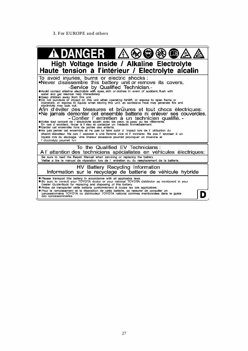
3. For EUROPE and others
27