gas turbines unit 3: gas turbines and jet …...gas turbines and jet propulsion: classification of...
TRANSCRIPT
�
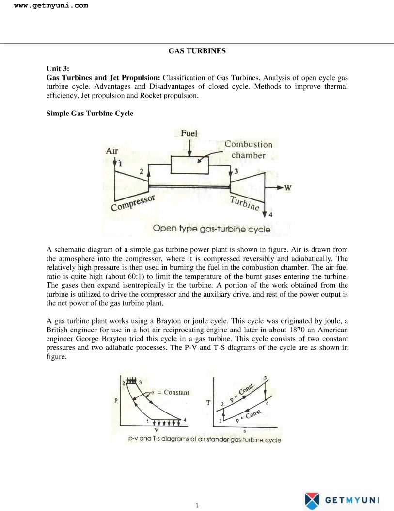
GAS TURBINES Unit 3: Gas Turbines and Jet Propulsion: Classification of Gas Turbines, Analysis of open cycle gas turbine cycle. Advantages and Disadvantages of closed cycle. Methods to improve thermal efficiency. Jet propulsion and Rocket propulsion. Simple Gas Turbine Cycle
A schematic diagram of a simple gas turbine power plant is shown in figure. Air is drawn from the atmosphere into the compressor, where it is compressed reversibly and adiabatically. The relatively high pressure is then used in burning the fuel in the combustion chamber. The air fuel ratio is quite high (about 60:1) to limit the temperature of the burnt gases entering the turbine. The gases then expand isentropically in the turbine. A portion of the work obtained from the turbine is utilized to drive the compressor and the auxiliary drive, and rest of the power output is the net power of the gas turbine plant. A gas turbine plant works using a Brayton or joule cycle. This cycle was originated by joule, a British engineer for use in a hot air reciprocating engine and later in about 1870 an American engineer George Brayton tried this cycle in a gas turbine. This cycle consists of two constant pressures and two adiabatic processes. The P-V and T-S diagrams of the cycle are as shown in figure.
www.getmyuni.com
1

�
Process 1 – 2: isentropic compression in the compressor Process 2 – 3: constant pressure heat addition in the combustion chamber Process 3 – 4: isentropic expansion in the turbine Process 4 -1: constant pressure heat rejection in the atmosphere or cooling of air in the intercooler (closed cycle). Expression of net work output: We have net work output, WN = WT - WC Turbine work, WT = h3 – h4 = CP (T3 – T4) since the working fluid is a perfect gas Compressor work, WC = h2 – h1 = CP (T2 – T1) ∴WN = CP (T3 – T4) – CP (T2 – T1)
Let ==1
2
PP
R pressure ratio for compression
t = T3/T1 = Temperature ratio
��
���
�+−−= 1
1
2
1
4
1
31 T
TTT
TT
TCW PN
We have r
rr
r
P
T
P
T1
2
21
1
1−− = r
rrr
RPP
TT 1
1
1
2
1
2−
−
=���
�
�=∴
1
3
3
4
1
4
TT
TT
TT
=
tR
tPP r
rr
r 11
3
4 1−−
��
�
�=���
�
�= 3241 & PPPP ==�
��
�
�
��
�
�+−−=∴
−
− 11
11r
r
rrPN R
R
ttTCW
Expression for Thermal Efficiency:
We have thermal efficiency, H
L
H
LH
H
Nth Q
QQQW
−=−
== 1η
www.getmyuni.com
2

�
Heat added, QH = h3 – h2 = CP (T3 – T2) Heat rejected, QL = h4 – h1 = CP (T4 – T1)
( )( )
��
���
�−
��
���
�−
−=−−
−=∴1
1
11
2
32
1
41
23
14
TT
T
TT
T
TTCTTC
P
Pthη
Now, r
r
rr
rrr
r
RPP
TTR
PP
TT
11
4
3
4
3
11
1
2
1
2 1&
−−−−
��
�
�=��
��==��
�
�
�=
But as P2 = P3 & P1 = P4, it follows that 1
3
1
4
4
3
1
2
TT
TT
orTT
TT
==
���
�
�−=−=∴
1
22
1 11.,.1
TT
eiTT
thth ηη or r
rth
R1
11 −−=η
From the above equation, it is seen that the efficiency of the air standard gas turbine cycle increases with increase in pressure ratio (R) and the type of working fluid. Optimum Pressure Ratio for Specific Power Output In a gas turbine cycle, T1 is the temperature of the atmosphere and T3 is the temperature of the burnt gases entering the turbine. Temperature T3 is fixed by the metallurgical consideration of the turbine and temperature T1 is fixed by the atmospheric condition. Between these two extreme values of temperature, there exists an optimum pressure ratio for which the work output of the turbine is maximum. We have, the net work output of the turbine is,
��
�
�
��
�
�−−−=
−
− 11
11r
r
rrPN R
R
ttTCW --- (1)
The optimum pressure ratio is obtained by differentiating the net work output w.r.t. the pressure
ratio and putting the derivative equal to zero i.e., 0=dR
dWN
Or 011
11 =���
�
�
���
�
�
�
�
�
�
�
�
−−−−
−γ
γ
γγ R
R
ttTC
dRd
P
Differentiating with respect to R we get,
www.getmyuni.com
3

�
011
11
=−−−−−−−−
γγγ
γγγ
γγ
γγ
RRt
i.e., γγγ
γγ
γγ 1
2111 −
− −=���
�
� −− RRt
γγγ
γγ
γγ 1
2111 −
− −=���
�
� −RRt
or tRort
R
R ==−−−
−
−
γγ
γ
γγ
γ 211
21
1
or ( )
tRortR ==−+−−
γγ
γγ 12211
or ( ) ( )12 −= γγ
tR opt i.e., ( )12
1
3−
��
���
�=
γγ
TT
Ropt
Substituting this value of R in the expression for WN, we get
( )( )
( )
�������
�
�
�������
�
�
+���
�
���
�−
���
�
���
�
−=
−
−−
−
1
1
121
12
1
rr
rr
rr
rr
PoptN t
t
ttTCW
��
�
�
��
�
�+−−= 12
1
211 t
t
ttTCP
��
���
�+−−= 12
121
1 tttTCP
��
���
�+−= 12 2
1
1 ttTCP
( ) ��
���
�−= 12
1
1 tTCW PoptN
www.getmyuni.com
4

�
( )r
r
rrr
rth
tR
1
12
1
11
11 −
−
−
���
�
���
�
−=−=η
( )21
11
toptth −=∴ η
In an ideal gas turbine plant, the compression and expansion processes are isentropic and there is no pressure-drop in the combustion chamber. But because of irreversibilities associated in the compressor and the turbine, and the pressure-drop in the actual flow passages and combustion chamber, an actual gas turbine plant differs from ideal one. The T-S diagram of actual plant is shown in figure.
www.getmyuni.com
5

�
12
12,hhhh
efficeincyCompressor SC −
−=∴ η
and the S
t hhhh
efficeincyturbine43
43,−−
=η
Comparison between Brayton cycle and Otto cycle:
1-2-3-4� Otto cycle 1-2-31-41� Brayton cycle For same comparison ratio and work capacity, the Brayton cycle handles a larger range of volume and a smaller range of pressure and temperatures than does the Otto cycle. In the reciprocating engine field, the Brayton cycle is not suitable. A reciprocating engine cannot efficiently handle a large volume flow of low pressure gas, for which the engine size (π/4 D2L) becomes large, and the friction losses also become more. So the Otto cycle is suitable in the reciprocating engine field. In turbine plants, however, the Brayton cycle, is more suitable than the Otto cycle. An I.C. engine is exposed to the highest temperature (after the combustion of fuel) only for a short while, and it gets time to become cool in the other processes of the cycle. On the other hand, a gas turbine plant, a steady flow device, is always exposed to the highest temperature used. So to protect material, the maximum temperature of gas that can be used in a gas turbine plant cannot be as high as in I.C. engine. Also, in the steady flow machinery, it is more difficult to carryout heat transfer at constant volume than at constant pressure. Also, a gas turbine can handle a large volume flow of gas quite efficiently.
www.getmyuni.com
6

�
Classification: Gas turbine are mainly divided into two group I Constant pressure combustion gas turbine i) Open cycle, ii) Closed cycle II Constant volume combustion gas turbine In almost all the field open cycle gas turbine plants are used. Closed cycle plants were introduced at one stage because of their ability to burn cheap fuel. Advantages and disadvantages of closed cycle over open cycle Advantages of closed cycle:
i) Higher thermal efficiency ii) Reduced size iii) No contamination iv) Improved heat transmission v) Improved part load η vi) Lesser fluid friction vii) No loss of working medium viii) Greater output and ix) Inexpensive fuel.
Disadvantages of closed cycle:
i) Complexity ii) Large amount of cooling water is required. This limits its use of stationary installation
or marine use iii) Dependent system iv) The wt of the system pre kW developed is high comparatively, ∴ not economical for
moving vehicles v) Requires the use of a very large air heater.
www.getmyuni.com
7

�
An Open cycle and Closed cycle Gas Turbine Engines
Methods to improve the performance of simple gas turbine plants I Regenerative Gas Turbine Cycle: The temperature of the exhaust gases in a simple gas turbine is higher than the temperature of the air after compression process. The η of the Brayton cycle can be increased by utilizing part of the energy of the exhaust gas from the turbine in heating up the air leaving the compression in a heat exchanger called a regenerator, thereby reducing the amount of heat supplied from an external source and also the amount of heat rejected. Figure shows a single stage regenerative gas turbine cycle
Air is drawn from the atmosphere into the compressor and is compressed isentropically to state 2. It is then heated at constant pressure in the regenerator to state x by the hot burnt gases from the gas turbine. Since the temperature of the air increases before it reaches the combustion chamber, less amount of fuel will be required to attain the designed turbine inlet temperature of the products of combustion. After combustion at constant pressure in the combustion chamber, the gas enters the turbine at state 3 and expands isentropically to state 4 in the turbine. It then enters the counter-flow regenerator as stated earlier, where it gives up a portion of its heat energy to the compressed air from the compressor and leaves the regenerator at state y.
�����
www.getmyuni.com
8

�
In an ideal cycle, the temperature of the air leaving the regenerator is equal to the temperature of the burnt gases leaving the turbine, i.e., Tx = T4. But in practice, the temperature of the air leaving the regenerator is less than Tx. In T-S diagram, Tx
1 is the temperature of the air leaving the regenerator in an actual plant.
∴Effectiveness of a regenerator is 2
21
TT
TT
x
xr −
−== ηε when CP is constant.
In an ideal regenerator, heat loss by the burnt gases is equal to the heat gained by the air in the regenerator, i.e., T4 – Ty = Tx – T2, Where Tx = T4 and Ty = T2 and hence ηr = 1
H
Lth Q
Q−= 1η
For an ideal regenerative gas turbine cycle, QL = CP (Ty – T1) = CP (T2 – T1) and QH = CP (T3 – Tx) = CP (T3 – T4)
( )( )
��
���
�−
��
���
�−
−=−−
−=∴
3
43
1
21
43
12
1
1
11
TT
T
TT
T
TTTT
thη
Since r
rr
rr
r
rrr
r
RPP
PP
TT
andRPP
TT
11
2
1
1
3
4
3
41
1
1
2
1
2 1−−−
−−
��
�
�=���
�
�=��
�
�
�==��
�
�
�=
rr
rr
rr
th Rt
R
R
t
1
1
1
.1
11
1
11
1−
−
−
−=
���
�
�
�−
���
�
�−
−=∴η
i.e., rr
th Rt
111
−
−=η
It is evident that the ηth of an ideal regenerative gas turbine cycle depends not only on the pressure ratio but also on the ratio of the two extreme temperatures. For a fixed ratio of T3/T1, the cycle η drops with increasing pressure ratio. In practice the regenerator is costly, heavy and bulky, and causes pressure losses which brings about a decrease in cycle η. II Ideal regenerative cycle with inter cooling and reheat: a) Gas turbine cycle with reheat and multistage expansion:
www.getmyuni.com
9
�
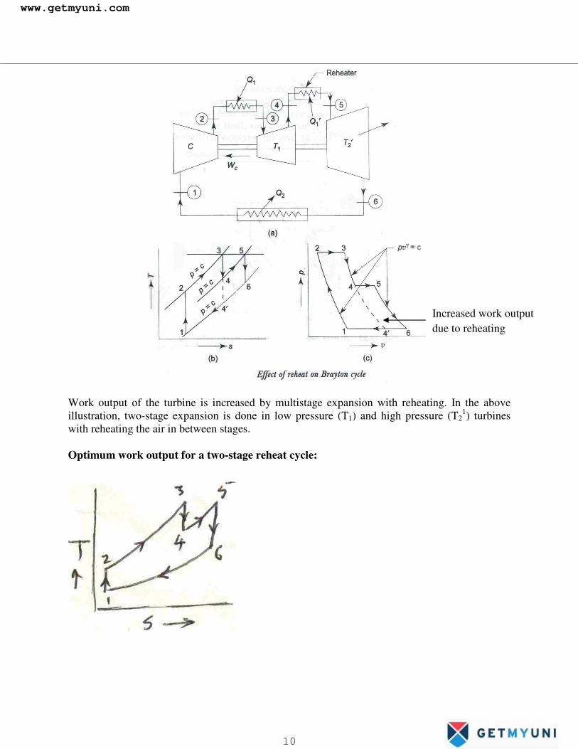
Work output of the turbine is increased by multistage expansion with reheating. In the above illustration, two-stage expansion is done in low pressure (T1) and high pressure (T2
1) turbines with reheating the air in between stages. Optimum work output for a two-stage reheat cycle:
Increased work output due to reheating
www.getmyuni.com
10
�
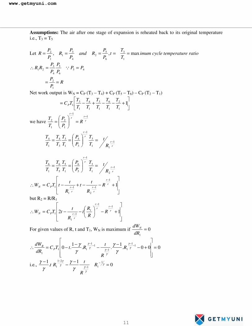
Assumptions: The air after one stage of expansion is reheated back to its original temperature i.e., T3 = T5
Let ratioetemperaturcycleimumTT
tPP
RandPP
RPP
R max,,1
3
6
52
4
31
1
2 =====
456
5
4
321 PP
PP
PP
RR ==∴ �
RPP
==1
2
Net work output is WN = CP (T3 – T4) + CP (T5 – T6) – CP (T2 – T1)
��
���
�+−−+−= 1
1
2
1
6
1
3
1
4
1
31 T
TTT
TT
TT
TT
TCP
we have rrr
r
RPP
TT 1
1
1
2
1
2−
−
=���
�
�=
r
r
rr
Rt
TT
PP
TT
TT
TT
1
11
3
1
3
4
1
3
3
4
1
4−
−
=���
�
�==
r
r
rr
Rt
TT
PP
TT
TT
TT
1
21
3
1
5
6
1
5
5
6
1
6−
−
=���
�
�==
��
�
�
��
�
�+−−+−=∴
−
−− 11
1
2
1
1
1r
r
rr
rrPN R
R
tt
R
ttTCW
but R2 = R/R1
��
�
�
��
�
�+−�
�
�
�−−=∴−
−
− 121
1
11
1
1r
rr
r
rrPN R
RR
tR
ttTCW
For given values of R, t and T1, WN is maximum if 01
=dR
dWN
000.1
..1
.0 11
11
11
111
=���
�
�
���
�
�
+−−−−−=∴ −−
−−
−γ
γ
γγ
γγ
γγ
γγ
R
R
tRtTC
dRdW
PR
i.e., 01
.1 1
11
21
1 =−−− −−
−γ
γγ
γγ
γγ
γγ
R
R
tRt
www.getmyuni.com
11
�
rr
rr
rr
rr
R
RRor
R
RR 21
1
1
11
1
1
121
1 −
−−
−
−−==
γγ
( )
rr
rr
RR1
21
1 −−
=
Or 21RR = i.e., RR =1
RR
RRR
R ===∴1
2
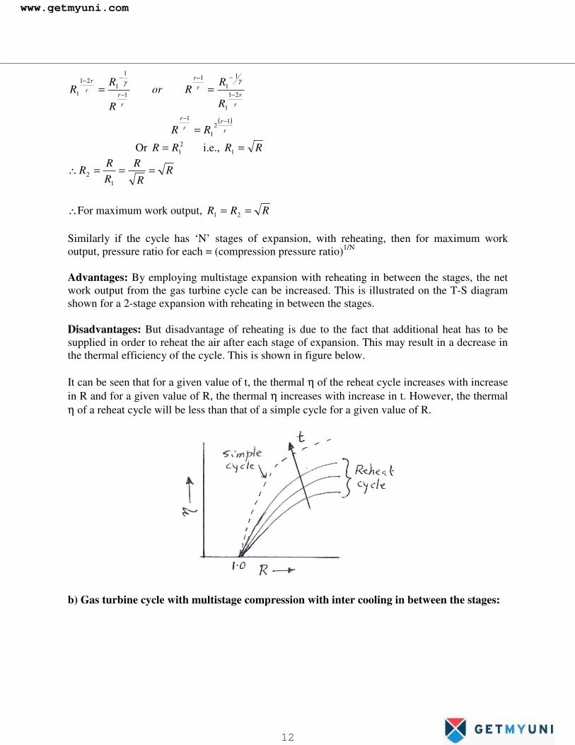
∴For maximum work output, RRR == 21 Similarly if the cycle has ‘N’ stages of expansion, with reheating, then for maximum work output, pressure ratio for each = (compression pressure ratio)1/N Advantages: By employing multistage expansion with reheating in between the stages, the net work output from the gas turbine cycle can be increased. This is illustrated on the T-S diagram shown for a 2-stage expansion with reheating in between the stages. Disadvantages: But disadvantage of reheating is due to the fact that additional heat has to be supplied in order to reheat the air after each stage of expansion. This may result in a decrease in the thermal efficiency of the cycle. This is shown in figure below. It can be seen that for a given value of t, the thermal η of the reheat cycle increases with increase in R and for a given value of R, the thermal η increases with increase in t. However, the thermal η of a reheat cycle will be less than that of a simple cycle for a given value of R.
b) Gas turbine cycle with multistage compression with inter cooling in between the stages:
www.getmyuni.com
12

�
Let 11
2 RPP
= 23
4 RPP = RP
P =6
5
For maximum work output, RRR == 21 The work output from a simple gas turbine cycle can be increased also by having multistage compression with inter cooling in between the stages. The effect of having two stage compression with inter cooling in between the stages is illustrated on the T-S diagram. It can be seen that, a higher work output has been achieved than that of simple cycle by an amount shown by the shaded area. The disadvantage of it is that more heat has to be supplied to heat the air than that is required for simple cycle. This may reduce the thermal ηof the cycle. c) Gas turbine cycle with two stage compression two-stage expansion and regenerator.
www.getmyuni.com
13

�
The thermal η of a gas turbine cycle may be improved by incorporating multistage compression with intercooling between the stages and multistage expansion with reheating between the turbines and also providing a regenerator. There is a definite saving of work due to multistage compression with intercooling arrangement between the stages. Similarly, the work output of the turbine is increased by multistage expansion with reheating. As a result, the net work of the plant increases.
The thermal efficiency of the cycle is given by H
Lth Q
Q−= 1η
( ) ( )( ) ( )7856
321101hhhhhhhh
−+−−+−
−=
Deviation of Practical gas turbine cycle from ideal cycle: 1) The working substance will not be air through out the cycle. Air is compressed in compressor
where as the products of combustion coming out of the combustion chamber is expanded in the turbine. The value of CP and γ will be different for expansion and heating as compared to compression process. For compression, CP = 1.005 kJ/kg-0K, γ = 1.4 For expansion, CP = 1.135 kJ/kg-0K, γ = 1.33
2) There will be pressure loss in the piping connecting the various components of the plant. ∴the pressure with which the products of combustion enters the turbine will be less than the
www.getmyuni.com
14

�
pressure with which air is coming out of the compressor i.e., the pressure ratio for expansion will be less than pressure ratio for compression.
3)
In a practical gas turbine cycle the compression and expansion processes are not isentropic but adiabatic with certain amount of frictional losses. The friction losses are accounted for by defining a parameter called isentropic efficiency.
a) Isentropic η of compression (ηC)
12
12
TTTT
ncompressioofworkActualncompressioofworkIsentropic S
C −−
==η
b) Isentropic η of turbine (ηT)
ST TT
TTworkturbineIsentropic
workturbineActual
43
43
−−
==η
To determination the air-fuel ratio:
1-2s isentropic work of compression 1-2 actual work of compression 3-4s isentropic turbine work 3-4 Actual turbine work
�
www.getmyuni.com
15
�
Let ma = mass of air entering the combustion chamber mf = mass of fuel entering the combustion chamber CV = Calorific value of fuel Applying SFEE to combustion chamber, we get, ma h2 + mf CV = (ma + mf) h3
÷by mf 32 1 hmm
CVhmm
f
a
f
a
��
�
�
�+=+
13 >>>>>≅f
a
f
a
mm
ashmm
( ) CVhhmm
f
a =−∴ 23
( )23 hhCV
mm
orf
a
−= ( )23
.,.TTC
CVmm
eiPf
a
−=
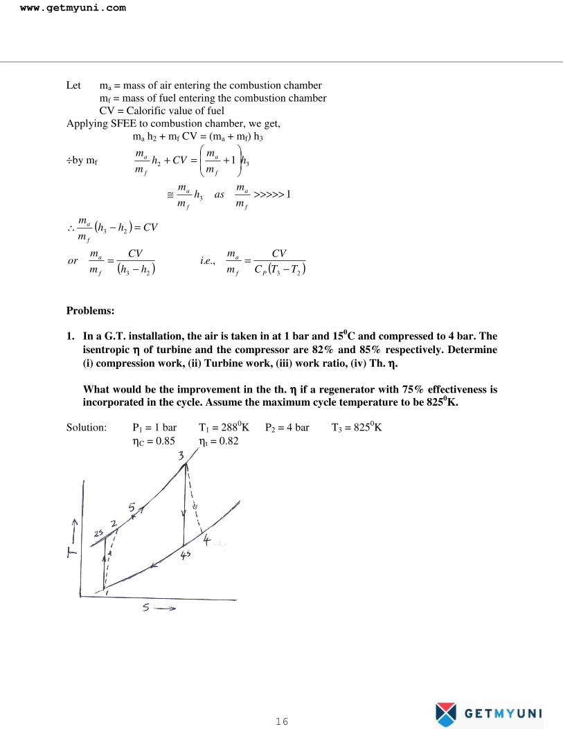
Problems: 1. In a G.T. installation, the air is taken in at 1 bar and 150C and compressed to 4 bar. The
isentropic ηηηη of turbine and the compressor are 82% and 85% respectively. Determine (i) compression work, (ii) Turbine work, (iii) work ratio, (iv) Th. ηηηη.
What would be the improvement in the th. ηηηη if a regenerator with 75% effectiveness is incorporated in the cycle. Assume the maximum cycle temperature to be 8250K.
Solution: P1 = 1 bar T1 = 2880K P2 = 4 bar T3 = 8250K ηC = 0.85 ηt = 0.82
www.getmyuni.com
16

�
Process 1-2 is isentropic i.e., r
r
s
PP
TT
1
1
2
1
2
−
���
�
�=
( ) KT s0
4.14.0
2 14.4284288 ==∴
But KTT
eiTTTT s
C0
2212
12 87.452288
28814.42885.0.,. =∴
−−=
−−
=η
Process 3-4 is isentropic 96.55441
825.,.4.14.0
4
1
3
4
3
4 =��
�
�=∴���
�
�=
−
s
rr
s TPP
TT
ei
But KTT
eiTTTT
st
04
4
43
43 57.60396.554825
82582.0.,. =∴
−−
=−−
=η
(i) Compressor work, WC = CP (T2 – T1) = 1.005 (452.87 – 288) = 165.69 kJ/kg (ii) Turbine work, Wt = CP (T3 – T4) = 1.005 (825 – 603.57) = 222.54 kJ/kg
(iii) Work ratio = 255.0=−
==T
CTR W
WWworkTurbineoutputworkNet
W
(iv) Th. η, ( ) 99.37385.56
87.45282569.16554.222 =
−−==
PH
netth CQ
Wη
= 15.2%
we have effectiveness 87.45257.603
87.45275.0 5
24
25
−−
==−−
=T
TTTT
∴T5 = 565.890K ∴Heat supplied, QH
1 = Q5-3 = CP(T3 – T5) = 1.005 (825 – 565.89) = 260.4 kJ/kg
218.04.260
85.561 ==
−=∴
H
CTth
Q
WWη
∴Improvement in ηth due to regenerator 152.0
152.0218.0 −=
= 0.436 i.e., 43.6%�
www.getmyuni.com
17
�
Problems: 1. In a G.T. installation, the air is taken in at 1 bar and 150C and compressed to 4 bar. The
isentropic ηηηη of turbine and the compressor are 82% and 85% respectively. Determine (i) compression work, (ii) Turbine work, (iii) work ratio, (iv) Th. ηηηη.
What would be the improvement in the th. ηηηη if a regenerator with 75% effectiveness is incorporated in the cycle. Assume the maximum cycle temperature to be 8250K.
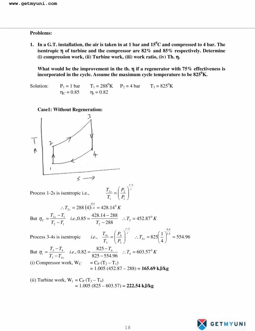
Solution: P1 = 1 bar T1 = 2880K P2 = 4 bar T3 = 8250K ηC = 0.85 ηt = 0.82 Case1: Without Regeneration:
Process 1-2s is isentropic i.e., r
r
s
PP
TT
1
1
2
1
2
−
���
����
�=
( ) KT s0
4.14.0
2 14.4284288 ==∴
But KTT
eiTTTT s
C0
2212
12 87.452288
28814.42885.0.,. =∴
−−=
−−
=η
Process 3-4s is isentropic 96.55441
825.,.4.14.0
4
1
3
4
3
4 =��
���
�=∴���
����
�=
−
s
rr
s TPP
TT
ei
But KTT
eiTTTT
st
04
4
43
43 57.60396.554825
82582.0.,. =∴
−−
=−−
=η
(i) Compressor work, WC = CP (T2 – T1) = 1.005 (452.87 – 288) = 165.69 kJ/kg (ii) Turbine work, Wt = CP (T3 – T4) = 1.005 (825 – 603.57) = 222.54 kJ/kg
www.getmyuni.com
18
�
(iii) Work ratio = T
CTR W
WWworkTurbineoutputworkNet
W−
== = 0.255
(iv) Thermal Effieciency η, ( ) 99.37385.56
87.45282569.16554.222 =
−−==
PH
netth CQ
Wη
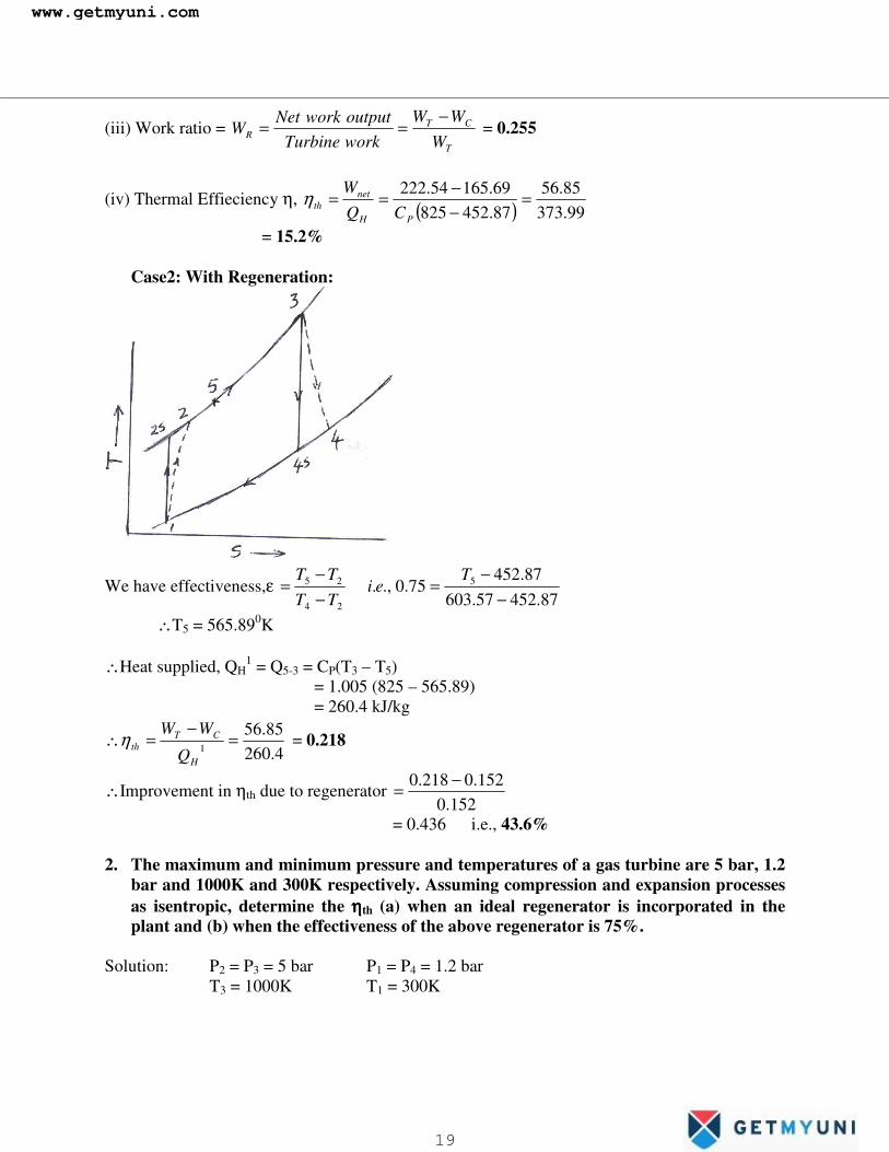
= 15.2% Case2: With Regeneration:
We have effectiveness,ε 87.45257.603
87.45275.0.,. 5
24
25
−−
=−−
=T
eiTTTT
∴T5 = 565.890K ∴Heat supplied, QH
1 = Q5-3 = CP(T3 – T5) = 1.005 (825 – 565.89) = 260.4 kJ/kg
4.26085.56
1 =−
=∴H
CTth
Q
WWη = 0.218
∴Improvement in ηth due to regenerator 152.0
152.0218.0 −=
= 0.436 i.e., 43.6% 2. The maximum and minimum pressure and temperatures of a gas turbine are 5 bar, 1.2
bar and 1000K and 300K respectively. Assuming compression and expansion processes as isentropic, determine the ηηηηth (a) when an ideal regenerator is incorporated in the plant and (b) when the effectiveness of the above regenerator is 75%.
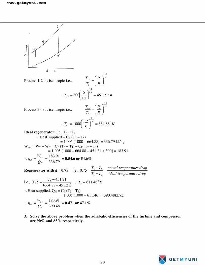
Solution: P2 = P3 = 5 bar P1 = P4 = 1.2 bar T3 = 1000K T1 = 300K
www.getmyuni.com
19
�
Process 1-2s is isentropic i.e., r
r
s
PP
TT
1
1
2
1
2
−
���
����
�=
KT s04.1
4.0
2 21.4512.1
5300 =�
�
���
�=∴
Process 3-4s is isentropic i.e., r
r
s
PP
TT
1
3
4
3
4
−
���
����
�=
KT s04.1
4.0
4 88.66452.1
1000 =��
���
�=∴
Ideal regenerator: i.e., T5 = T4 ∴Heat supplied = CP (T3 – T5) = 1.005 [1000 – 664.88] = 336.79 kJ/kg Wnet = WT – WC = CP (T3 – T4) – CP (T2 – T1) = 1.005 [1000 – 664.88 – 451.21 + 300] = 183.91
79.33691.183==∴
H
netth Q
Wη = 0.54.6 or 54.6%
Regenerator with εεεε = 0.75 i.e., dropetemperaturidealdropetemperaturactual
TTTT
=−−
=24
2575.0
i.e., ( ) KTT 0
55 46.611
21.45188.66421.451
75.0 =∴−
−=
∴Heat supplied, QH = CP (T3 – T5) = 1.005 (1000 – 611.46) = 390.48kJ/kg
48.39091.183==∴
H
netth Q
Wη = 0.471 or 47.1%
3. Solve the above problem when the adiabatic efficiencies of the turbine and compressor
are 90% and 85% respectively.
www.getmyuni.com
20
�
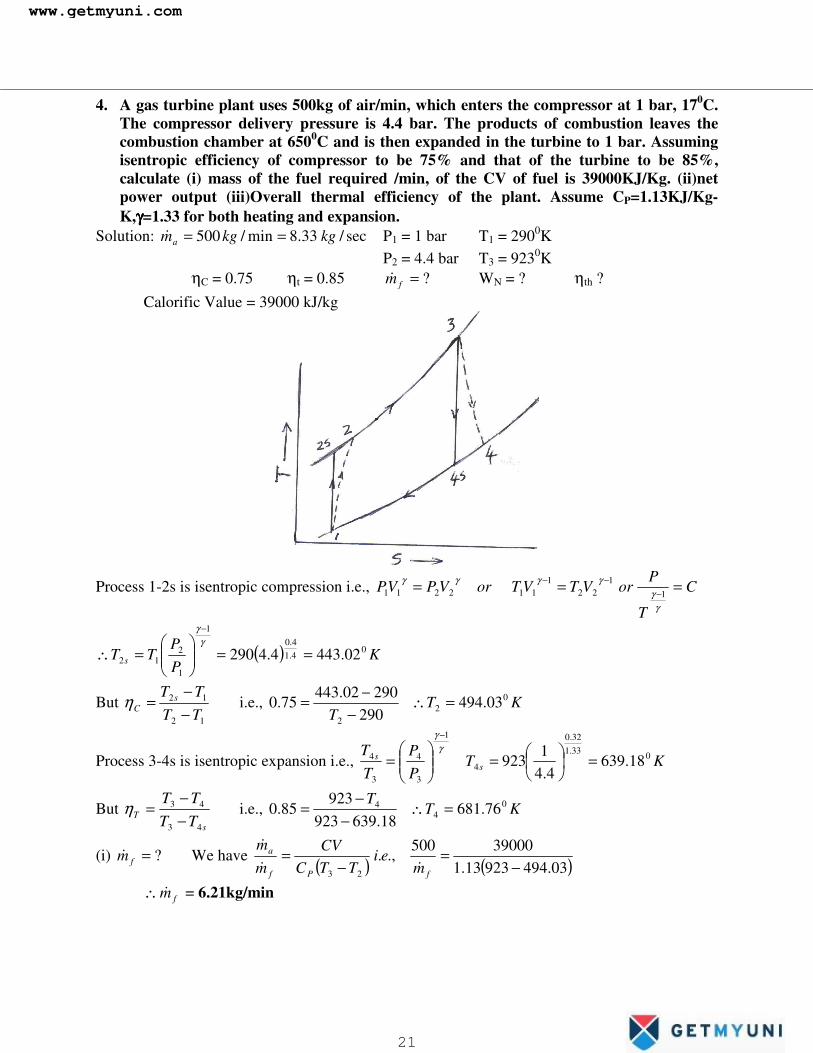
4. A gas turbine plant uses 500kg of air/min, which enters the compressor at 1 bar, 170C. The compressor delivery pressure is 4.4 bar. The products of combustion leaves the combustion chamber at 6500C and is then expanded in the turbine to 1 bar. Assuming isentropic efficiency of compressor to be 75% and that of the turbine to be 85%, calculate (i) mass of the fuel required /min, of the CV of fuel is 39000KJ/Kg. (ii)net power output (iii)Overall thermal efficiency of the plant. Assume CP=1.13KJ/Kg-K,γγγγ=1.33 for both heating and expansion.
Solution: sec/33.8min/500 kgkgma ==� P1 = 1 bar T1 = 2900K P2 = 4.4 bar T3 = 9230K ηC = 0.75 ηt = 0.85 ?=fm� WN = ? ηth ? Calorific Value = 39000 kJ/kg
Process 1-2s is isentropic compression i.e., C
T
PorVTVTorVPVP === −
−−
γγ
γγγγ1
122
1112211
( ) KPP
TT s0
4.14.0
1
1
212 02.4434.4290 ==��
�
����
�=∴
−γ
γ
But 12
12
TTTT s
C −−
=η i.e., KTT
02
2
03.494290
29002.44375.0 =∴
−−=
Process 3-4s is isentropic expansion i.e., KTPP
TT
ss 033.1
32.0
4
1
3
4
3
4 18.6394.4
1923 =�
�
���
�=���
����
�=
−γ
γ
But s
T TTTT
43
43
−−
=η i.e., KTT 0
44 76.68118.639923
92385.0 =∴
−−
=
(i) ?=fm� We have ( ) ( )03.49492313.139000500
.,.23 −
=−
=fPf
a
mei
TTCCV
mm
��
�
∴ fm� = 6.21kg/min
www.getmyuni.com
21

�
(ii) WN = ? Compressor work, WC = CP (T2 – T1) = 1.005 (494.03 – 290) = 205.05 kJ/kg Turbine work, WT = CP (T3 – T4) = 1.13 (923 – 681.76) = 272.6 kJ/kg ∴WN = WT – WC = 67.55 kJ/kg ∴Net work output per minute = ( ) Nfa Wmm �� + = (500+6.21) (67.55) = 34194.49 kJ/min
∴Power output 60
49.34194= = 569.91 kW
(iii) ηth = ? Heat supplied, QH = CP (T3 – T2) = 1.33 (923 – 494.03) = 570.53 kJ/kg
53.57055.67==∴
H
Nth Q
Wη = 0.118 or 11.8%
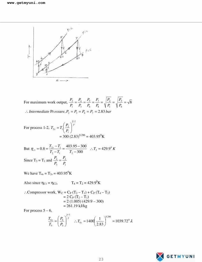
5. A G.T. cycle having 2 stage compression with intercooling in between stages and 2
stages of expansion with reheating in between the stages has an overall pressure ratio of 8. The maximum cycle temperature is 14000K and the compressor inlet conditions are 1 bar and 270C. The compressors have ηηηηs of 80% and turbines have ηηηηs of 85%. Assuming that the air is cooled back to its original temperature after the first stage compression and gas is reheated back to its original temperature after 1st stage of expansion, determine (i) the net work output (ii) the cycle ηηηηth.
Solution: barPP
81
4 = T5 = 14000K T1 = 3000K, P1= 1 bar
ηC1= 0.8 = ηC2, ηt1 = ηt2 = 0.85 ,
T3 = T1 T7 = T5
www.getmyuni.com
22
�
For maximum work output, 88
5
1
4
8
7
6
5
3
4
1
2 ======PP
PP
PP
PP
PP
PP
barPPPPessureteIntermedia 83.2,Pr 7632 ====∴ �
For process 1-2, γ
γ 1
1
212
−
���
����
�=
PP
TT s
= 300 (2.83)0.286 = 403.950K
But KTTTT
TT sc
02
212
121 9.429
30030095.403
8.0 =∴−
−=−−
==η
Since T3 = T1 and 1
2
3
4
PP
PP
=
We have T4s = T2s = 403.950K Also since ηC1 = ηC2, T4 = T2 = 429.90K ∴Compressor work, WC = CP (T2 – T1) + CP (T4 – T3) = 2 CP (T2 – T1) = 2 (1.005) (429.9 – 300) = 261.19 kJ/kg For process 5 – 6,
λγ
γ
0286.0
6
1
5
6
5
6 72.103983.21
1400 =��
���
�=∴���
����
�=
−
ss T
PP
TT
www.getmyuni.com
23

�
But KTT
eiTTTT
st
06
6
65
651 76.1093
72.103914001400
85.0.,. =∴−
−=
−−
=η
Since T7 = T5 and 8
7
6
5
PP
PP
= , then T8 = T6
Since ηt1 = ηt2, T6 = T8 = 1093.760K ∴Turbine work, Wt = CP (T5 – T6) + CP (T7 – T8) = 2 CP (T5 – T6) = 2 (1.005) (1400 – 1093.76) = 615.54 kJ/kg ∴WN = WT – WC = 354.35 kJ/kg ηth = ? Heat Supplied, QH = CP (T5 – T4) + CP (T7 – T6) = 1.005 (1400 – 429.9 + 1400 – 1093.76) = 1282.72 kJ/kg
72.128235.354=∴ thη = 0.276 or 27.6%
6. Determine the ηηηη of a gas turbine having two stages of compression with intercooling
and two stages of expansion with reheat. Given that the pressure ratio is 4, minimum temperature of the cycle 270C and maximum temperature of the cycle is 6000C, when ηηηηt, ηηηηC and regenerator ηηηη are equal to 80%.
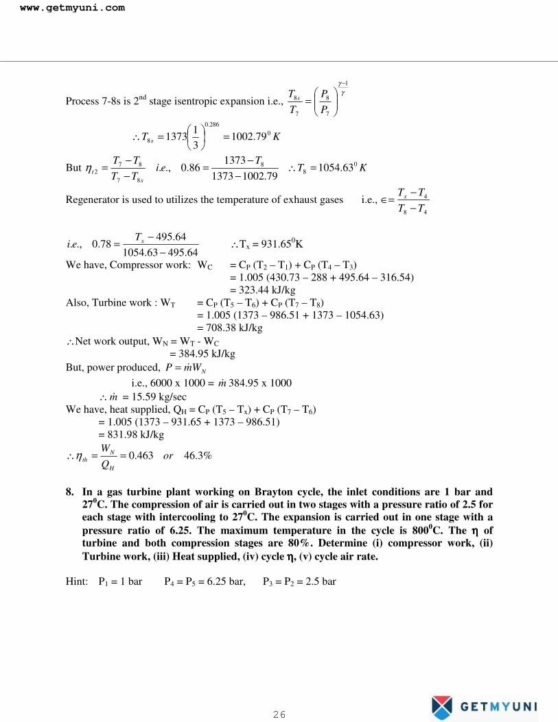
7. A two stage gas turbine cycle receives air at 100 kPa and 150C. The lower stage has a
pressure ratio of 3, while that for the upper stage is 4 for the compressor as well as the turbine. The temperature rise of the air compressed in the lower stage is reduced by 80% by intercooling. Also, a regenerator of 78% effectiveness is used. The upper temperature limit of the cycle is 11000C. The turbine and the compressor ηηηηs are 86%. Calculate the mass flow rate required to produce 6000kW.
Solution: P1 = 1 bar T1 = 2880K 4,33
4
1
2 ==PP
PP
ηIC = 0.8
� = ηreg = 0.78, T5 = 13730K, ηC1 = ηC2 = ηt1 = ηt2 = 0.86 ?=m� if P = 6000 kW
www.getmyuni.com
24

�
Process 1-2s is isentropic compression γ
γ 1
1
2
1
2
−
���
����
�=∴
PP
TT s
∴T2s = 288 (3)0.286 = 410.750K
But KTT
eiTTTT s
C0
2212
121 73.430
28828875.410
86.0.,. =∴−
−=−−
=η
Also, KTT
eiTTTT
IC0
33
12
32 54.31628873.430
73.4308.0.,. =∴
−−
=−−
=η
Process 3-4s is 2nd stage isentropic compression γ
γ 1
3
4
3
4
−
���
����
�=∴
PP
TT s
∴T4s = 316.54 (4)0.286 = 470.570K
But KTT
eiTTTT s
C0
4434
342 64.495
54.31654.31657.470
86.0.,. =∴−
−=−−
=η
Process 5-6s is 1st stage isentropic expansion γ
γ 1
5
6
5
6
−
���
����
�=∴
PP
TT s
KT s0
286.0
6 59.92341
1373 =��
���
�=∴
But KTT
eiTTTT
st
06
6
65
651 51.986
59.92313731373
86.0.,. =∴−
−=
−−
=η
Process 6-7 is reheating, assume T7 = T5 = 13730K
www.getmyuni.com
25
�
Process 7-8s is 2nd stage isentropic expansion i.e., γ
γ 1
7
8
7
8
−
���
����
�=
PP
TT s
KT s0
286.0
8 79.100231
1373 =��
���
�=∴
But KTT
eiTTTT
st
08
8
87
872 63.1054
79.100213731373
86.0.,. =∴−
−=
−−
=η
Regenerator is used to utilizes the temperature of exhaust gases i.e., 48
4
TTTTx
−−
∈=
64.49563.105464.495
78.0.,.−
−= xT
ei ∴Tx = 931.650K
We have, Compressor work: WC = CP (T2 – T1) + CP (T4 – T3) = 1.005 (430.73 – 288 + 495.64 – 316.54) = 323.44 kJ/kg Also, Turbine work : WT = CP (T5 – T6) + CP (T7 – T8) = 1.005 (1373 – 986.51 + 1373 – 1054.63) = 708.38 kJ/kg ∴Net work output, WN = WT - WC = 384.95 kJ/kg But, power produced, NWmP �= i.e., 6000 x 1000 = m� 384.95 x 1000 ∴ m� = 15.59 kg/sec We have, heat supplied, QH = CP (T5 – Tx) + CP (T7 – T6) = 1.005 (1373 – 931.65 + 1373 – 986.51) = 831.98 kJ/kg
%3.46463.0 orQW
H
Nth ==∴η
8. In a gas turbine plant working on Brayton cycle, the inlet conditions are 1 bar and
270C. The compression of air is carried out in two stages with a pressure ratio of 2.5 for each stage with intercooling to 270C. The expansion is carried out in one stage with a pressure ratio of 6.25. The maximum temperature in the cycle is 8000C. The ηηηη of turbine and both compression stages are 80%. Determine (i) compressor work, (ii) Turbine work, (iii) Heat supplied, (iv) cycle ηηηη, (v) cycle air rate.
Hint: P1 = 1 bar P4 = P5 = 6.25 bar, P3 = P2 = 2.5 bar
www.getmyuni.com
26
�
9. The pressure ratio of an open cycle constant pressure gas turbine is 6. The temperature
range of the plant is 150C and 8000C. Calculate (i) ηηηηth of the plant, (ii) Power developed by the plant for an air circulation of 5 kg/s, (iii) Air fuel ratio, (iv) specific fuel consumption. Neglect losses in the system. Use the following data: for both air and gases: CP 1.005 kJ/kg0K and γγγγ = 1.4. Calorific value of the fuel is 42000 kJ/kg, ηηηηC = 0.85, ηηηηt = 0.9 and combustion ηηηη of 0.95.
10. In a G.T. unit with two stage compression and two stage expansion the gas temperature
at entry to both the turbines are same. The compressors have an intercooler with an effectiveness of 83%. The working temperature limits are 250C and 10000C, while the pressure limits are 1.02 bar and 7 bar respectively. Assuming that the compression and expansion processes in the compressors and turbine are adiabatic with ηηηηC of 84% and ηηηηt of 89% for both the stages. Calculate (i) the air-fuel ratio at the combustion chambers if the calorific value of the fuel is 38500 kJ/kg, (ii) Power output in kW for an air flow rate of 1kg/s and (iii) overall cycle ηηηη.�
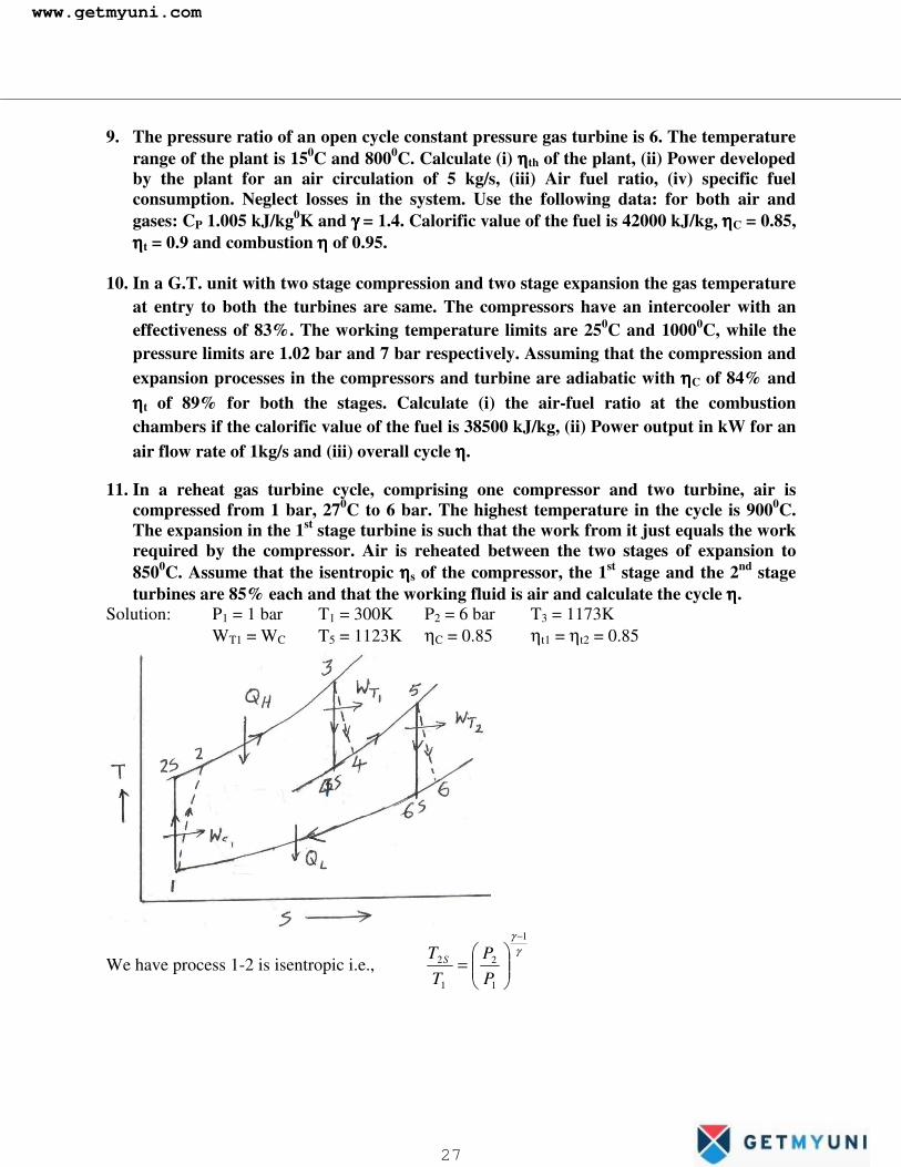
11. In a reheat gas turbine cycle, comprising one compressor and two turbine, air is compressed from 1 bar, 270C to 6 bar. The highest temperature in the cycle is 9000C. The expansion in the 1st stage turbine is such that the work from it just equals the work required by the compressor. Air is reheated between the two stages of expansion to 8500C. Assume that the isentropic ηηηηs of the compressor, the 1st stage and the 2nd stage turbines are 85% each and that the working fluid is air and calculate the cycle ηηηη.
Solution: P1 = 1 bar T1 = 300K P2 = 6 bar T3 = 1173K WT1 = WC T5 = 1123K ηC = 0.85 ηt1 = ηt2 = 0.85
We have process 1-2 is isentropic i.e., γ
γ 1
1
2
1
2
−
���
����
�=
PP
TT S
www.getmyuni.com
27
�
KT S 5.50016
3004.14.0
2 =��
���
�=∴
KTT
eiTTTT
But SC 536
3003005.500
85.0.,. 2212
12 =∴−
−=−−
=η
∴Compressor work, WC = CP (T2 – T1) = 1.005 (536 – 300) = 237 kJ/kg From data, WT1 = WC = 237 kJ/kg = CP (T3 – T4) ∴T4 = 937 kJ/kg
KTT
eiTTTT
But SSS
t 8951173
937117385.0.,. 4
443
431 =∴
−−=
−−
=η
Process 3-4 is isentropic i.e., 1
3
4
3
4−
���
����
�=
γγ
TT
PP S
barP 328.21173895
64.04.1
4 =��
���
�=∴
From T-S diagram, intermediate pressure, P4 = P5 = 2.328 bar Process 5-6s is isentropic in the 2nd stage turbine
KTPP
TT
ei SS 882
328.21
1123.,.4.14.0
6
1
5
6
5
6 =��
���
�=∴���
����
�=
−γ
γ
KTT
eiTTTT
ButS
t 9188821123
112385.0.,. 6
6
65
652 =∴
−−=
−−=η
∴WT2 = CP (T5 – T6) = 1.005 (1123 – 918) = 206 kJ/kg ∴Net work output = WT – WC = (WT1 + WT2) – WC = 206 kJ/kg Net heat transfer or heat supplied, Q = QH + QR = CP (T3 – T2) + CP (T5 – T4) = 640 + 187 = 827 kJ/kg
∴Cycle efficiency, %25827206 ===
net
netcycle Q
Wη
www.getmyuni.com
28

�
12. In a simple gas turbine unit, the isentropic discharge temperature of air flowing out of compressor is 1950C, while the actual discharge temperature is 2400C. Conditions of air at the beginning of compression are 1 bar and 170C. If the air-fuel ratio is 75 and net power output from the unit is 650kW. Compute (i) isentropic ηηηη of the compressor and the turbine and (ii) overall ηηηη. Calorific value of the fuel used is 46110 kJ/kg and the unit consumes 312 kg/hr of fuel. Assume for gases CP = 1.09 kJ/kg-K and γγγγ = 1.32 and for air CP = 1.005 kJ/kg-K and γγγγ = 1.4.
Solution: T2S = 195+273 = 468 K T2 = 240+273 = 513K T1 = 290K P1=1bar A/F = 75, Power output = Wnet = WT – WC = 650kW ηC = ? ηT = ? ηcycle = ? CV = 46110 kJ/kg skghrkgm f /0867.0/312 ==� CPg = 1.09 kJ/kg-k, γg = 1.30
CPa = 1.005 kJ/kg-K, γa = 1.4
We have, Compressor Efficiency, 79.0290513290468
.,.12
12 =−−
−−
= eiTTTT S
Cη
Also, fa mFA
m �� ��
���
�=
= 75 (0.0867) = 6.503 kg/s
34.5290468
Pr4.04.1
1
1
2 =��
���
�=���
����
�==
−γγ
TT
Rratioessure S
Applying SFEE to the constant pressure heating process 2-3, ( ) ( )23 TTCmmCVm Pgfaf −+= ��� 0.0867 (46110) = (6.503 + 0.0867) 1.09 (T3 – 513) ∴T3 = 1069.6K
Also, ( ) 32.1132.1
4
1
3
4
3
4 34.56.1069−
−
=∴���
����
�= S
S TPP
TT g
g
γγ
∴T4S = 712.6K Further, ( ) ( ) ( ) ( )1243 TTCmTTCmmWWW PaaPgfaCTnet −−−+=−= ������
www.getmyuni.com
29

�
i.e., 650 = (6.503 + 0.0867) 1.09 (1069.6 – T4) – 6.503 (1.005) (513 – 290) ∴T4 = 776K
Now, Turbine Efficiency, 822.06.7126.1069
7766.1069
43
43 =−−=
−−
=S
T TTTTη
And, ( ) 163.0461100867.0
650 ===CVm
W
f
netcycle
�η
Or
( ) ( ) 162.09.3997
650650
23
==−+
==TTCmmQ
W
PgfaH
netcycle
��η
�
�
www.getmyuni.com
30

�
Problems: 1. In an open cycle gas turbine plant air enters the compressor at 1 bar and 270C. The pressure
after compression is 4 bar. The isentropic ηs of the turbine and compressor are 85% and 80% respectively. Air fuel ratio is 80:1. CV of the fuel used is 42000 kJ/kg. Mass flow rate of air is 2.5 kg/s. Determine the power output from the plant and the cycle η. Assume CP and γ to be same for both air and products of combustion.
Solution: P1 = 1 bar T1 = 300K P2 = 4 bar ηC = 80% ηT = 85% A/F = 80:1 CV = 42000kJ/kg skgma /5.2=� Power output = ? ηcycle = ? CP = 1.005 γ = 1.4
Process 1-2s is isentropic
( ) KTPP
TT
ei SS 8.4454300.,. 286.0
2
1
1
2
1
2 ==∴���
����
�=
−γ
γ
3003008.445
8.0.,.212
12
−−=
−−
=T
eiTTTT
But SCη ∴T2 = 482.3K
Heat addition rate during process 2-3, ( ) ( )23 TTCmmCVmQ PfafH −+== ����
skgm
mmmBut
a
faf /03125.0
805.2 ===
�
���
( )4200003125.0=∴ HQ� = 1312.5 = (2.5 + 0.03125) 1.005 (T3 – 482.3) ∴T3 = 998.2K
Process 3-4s is isentropic γ
γ 1
3
4
3
4.,.
−
���
����
�=
PP
TT
ei S
www.getmyuni.com
31

�
KT S 6.67141
2.998286.0
4 =��
���
�=∴
KTT
eiTTTT
ButS
T 6.7206.6712.998
2.99885.0.,. 4
4
43
43 =∴−
−=
−−
=η
Power output, ( ) netfa WmmP �� +=
( ) ( ) ( )1243 TTCmTTCmm PaPfa −−−+= ��� = 247.6kW
%9.185.13126.247 ===
H
netcycle Q
Wη
2. A gas turbine power plant operates on ideal Brayton cycle. The minimum and maximum
temperature in the cycle are respectively T1 = 300K and T3 = 800K. Find the value of the optimum pressure ratio for maximum specific work output and the cycle η for this condition. Is it possible to improve this cycle η by including a regenerator, substantiate?
Solution: T1 = 300K T2 = 800K We know that, for a given T1 and T3, the work output of a Brayton cycle is maximum when the pressure ratio is such that T2 = T4. Let R = optimum pressure ratio
Process 1-2 and 3-4 are isentropic and in each case the pressure ratio is same i.e., R
We have ( ) γγ
γγ
1
34
1
12
1&
−−
��
���
�==R
TTRTT
( )( ) γ
γγ
γ
13
1
142 .,., −
−==
R
TRTeiTTAs
( )21
1
31
���
����
�=∴
−
TT
R γγ
www.getmyuni.com
32
�
( )12
1
3.,.−
���
����
�=
γγ
TT
Rei
( )57.5
300800
,4.02
4.1
=��
���
�=∴ RratiopressureOptimum
Also, T2 = 300 (5.57)0.286 = 490K = T4 ( ) ( )
( ) 387.023
1243 =−
−−−==∴
TTCTTCTTC
QW
P
PP
H
netcycleη
A regenerator can be used if and only T4 > T2. Here T4 = T2 and hence η of the cycle can not be increased by incorporating a regenerator. 3. A simple gas turbine plant operating on the Brayton cycle has air entering the compressor at
100KPa and 270C. The pressure ratio is 9.0 and the maximum cycle temperature is 7270C. What will be the %ge change in cycle η and net work output if the expansion in the turbine is divided into two stages each of pressure ratio 3, with intermediate reheating to 7270C? Assume compression and expansion are ideal isentropic.
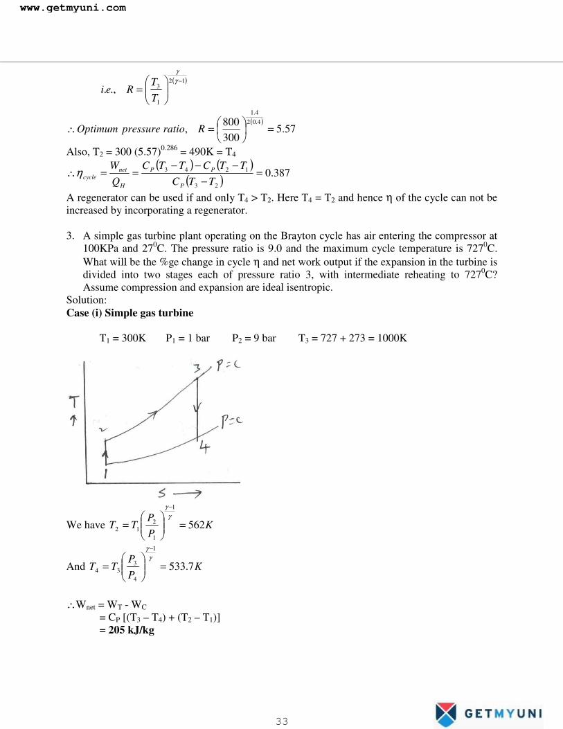
Solution: Case (i) Simple gas turbine T1 = 300K P1 = 1 bar P2 = 9 bar T3 = 727 + 273 = 1000K
We have KPP
TT 562
1
1
212 =��
�
����
�=
−γ
γ
And KPP
TT 7.533
1
4
334 =��
�
����
�=
−γ
γ
∴Wnet = WT - WC = CP [(T3 – T4) + (T2 – T1)] = 205 kJ/kg
www.getmyuni.com
33

�
QH = CP (T3 – T2) = 440.19 kJ/kg
19.440205==∴
H
netcycle Q
Wη = 0.466 or 46.6%
Case (ii) With reheat: From Case (i), T2 = 562K
546
5
4
3 3 PPandPP
PP
===
We have, KPP
TT 6.730
1
4
334 =��
�
����
�=
−γ
γ
KPP
TT 6.730
1
6
556 =��
�
����
�=
−γ
γ
Wnet = (WT1 + WT2 – WC) = CP (T3 – T4) + CP (T5 – T6) – CP (T2 – T1) = 278 kJ/kg
( ) ( )4523
278TTCTTCQ
W
PPH
netcycle −+−
==∴η = 0.391 or 39.1%
∴Increase in net work output 205
205278 −= = 0.356 or 35.6%
Increase in efficiency 6.46
6.461.39 −= = -0.161 or -16/1%
Negative sign indicates there is a decrease in Thermal Efficiency �
www.getmyuni.com
34

�
Ideal Jet-Propulsion Cycles: Gas turbine engines are widely used to power air-crafts because they are light and compact and have a high power-to-weight ratio. Air craft gas turbine operates on an open cycle called a jet- propulsion cycle. The ideal jet propulsion cycle differs from the simple ideal Brayton cycle in that the gases are not expanded to the ambient pressure in the turbine. Instead, they are expanded to a pressure such that the power produced by the turbine is just sufficient to drive the compressor and the auxiliary equipment, such as a small generator and hydraulic pumps. That is, the net work output of a jet propulsion cycle is zero. The gases that exit the turbine at relatively high pressure are subsequently accelerated in a nozzle to provide the thrust to propel the air craft. Also, air craft gas turbine operate at higher pressure ratios (typically between 10-25), and the fluid passes through a diffuser first, where it is decelerated and its pressure is increased before it enters the compressor.
Air standard Jet Propulsion cycle:
An air standard Brayton or Joule cycle is the basic cycle for jet propulsion. The jet engine consists practically of the same type of components as in gas turbine plants, namely a compressor, a combustion chamber and a turbine. The only difference is that, the former also consists of an inlet diffuser, where the air entering from the atmosphere is decelerated and
www.getmyuni.com
35

�
slightly compressed, and an exit nozzle, where the products of combustion expand to the pressure of the surroundings with increase in relative velocity. Such a plant and the corresponding T-S diagram are shown in Fig. In this plant, the work output of the turbine is just sufficient to drive the compressor. Air enters the diffuser from the atmosphere, is slightly compressed from state 1 to state 11. It then enters the compressor, where it is further compressed to state 2. The compressed air then flows into the combustion chamber where it burns the fuel at constant pressure from state 2 to state 3 and the products of combustion then expand in the turbine from state 3 to state 4 developing power which is just sufficient to drive the compressor. Further expansion of the burnt gases takes place in the exit nozzle at state 5, after which the gases make an exit into the atmosphere with a very high velocity. The momentum of the exhaust gases flowing at high velocity from the nozzle result in a thrust upon the aircraft on which the engine is installed. In an actual jet propulsion plant, there is a slight pressure drop in the combustion chamber and the processes of combustion and expansion are not strictly reversible adiabatic. The thrust of a jet plane is the propulsive force i.e.,
( ) 515 vmvvmF fa �� +−= where am� = mass flow rate of air,
51 & vv = inlet and exit velocity of the fluid fm� = mass flow rate of fuel in the combustion chamber
but since fm� is very small, 5vm f� term is neglected.
( )15 vvmF a −=∴ � Turbo jet:
Figure shows a turbo jet unit. Power produced by the turbine is just sufficient to drive the compressor. The exhaust gases from the turbine which are at a higher pressure than atmosphere are expanded in the nozzle and a very high velocity jet is produced which provides a forward motion to the air-craft by the jet reaction (Newton’s third law of motion). At higher speeds the turbo jet gives higher propulsion efficiency. The turbo-jets are most suited to the air-crafts traveling above 800 km/hr. The overall η of a turbo jet is the product of the thermal η of the gas turbine plant and the propulsive η of the jet (nozzle).
www.getmyuni.com
36
�
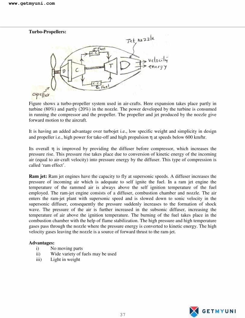
Turbo-Propellers:
Figure shows a turbo-propeller system used in air-crafts. Here expansion takes place partly in turbine (80%) and partly (20%) in the nozzle. The power developed by the turbine is consumed in running the compressor and the propeller. The propeller and jet produced by the nozzle give forward motion to the aircraft. It is having an added advantage over turbojet i.e., low specific weight and simplicity in design and propeller i.e., high power for take-off and high propulsion η at speeds below 600 km/hr. Its overall η is improved by providing the diffuser before compressor, which increases the pressure rise. This pressure rise takes place due to conversion of kinetic energy of the incoming air (equal to air-craft velocity) into pressure energy by the diffuser. This type of compression is called ‘ram effect’. Ram jet: Ram jet engines have the capacity to fly at supersonic speeds. A diffuser increases the pressure of incoming air which is adequate to self ignite the fuel. In a ram jet engine the temperature of the rammed air is always above the self ignition temperature of the fuel employed. The ram-jet engine consists of a diffuser, combustion chamber and nozzle. The air enters the ram-jet plant with supersonic speed and is slowed down to sonic velocity in the supersonic diffuser, consequently the pressure suddenly increases to the formation of shock wave. The pressure of the air is further increased in the subsonic diffuser, increasing the temperature of air above the ignition temperature. The burning of the fuel takes place in the combustion chamber with the help of flame stabilization. The high pressure and high temperature gases pass through the nozzle where the pressure energy is converted to kinetic energy. The high velocity gases leaving the nozzle is a source of forward thrust to the ram-jet. Advantages:
i) No moving parts ii) Wide variety of fuels may be used iii) Light in weight
www.getmyuni.com
37
�
The major short coming of ram-jet engine is that it cannot be started of its own. It has to be accelerated to certain flight velocity by some launching device. It is always equipped with a small turbo-jet which starts the ram-jet. Rocket Propulsion: Similar to jet propulsion, the thrust required for rocket propulsion is produced by the high velocity jet of gases passing through the nozzle. But the main difference is that in case of jet propulsion the oxygen required for combustion is taken from the atmosphere and fuel is stored whereas for rocket engine, the fuel and oxidizer both are contained in a propelling body and as such it can function in vacuum also. Rockets are classified as follows: I According to the type of propellants
i) Solid propellant rocket ii) Liquid propellant rocket
II According to the number of motors
i) Single-stage rocket (consists of one rocket motor) ii) Multi-stage rocket (consists more than one rocket motor)
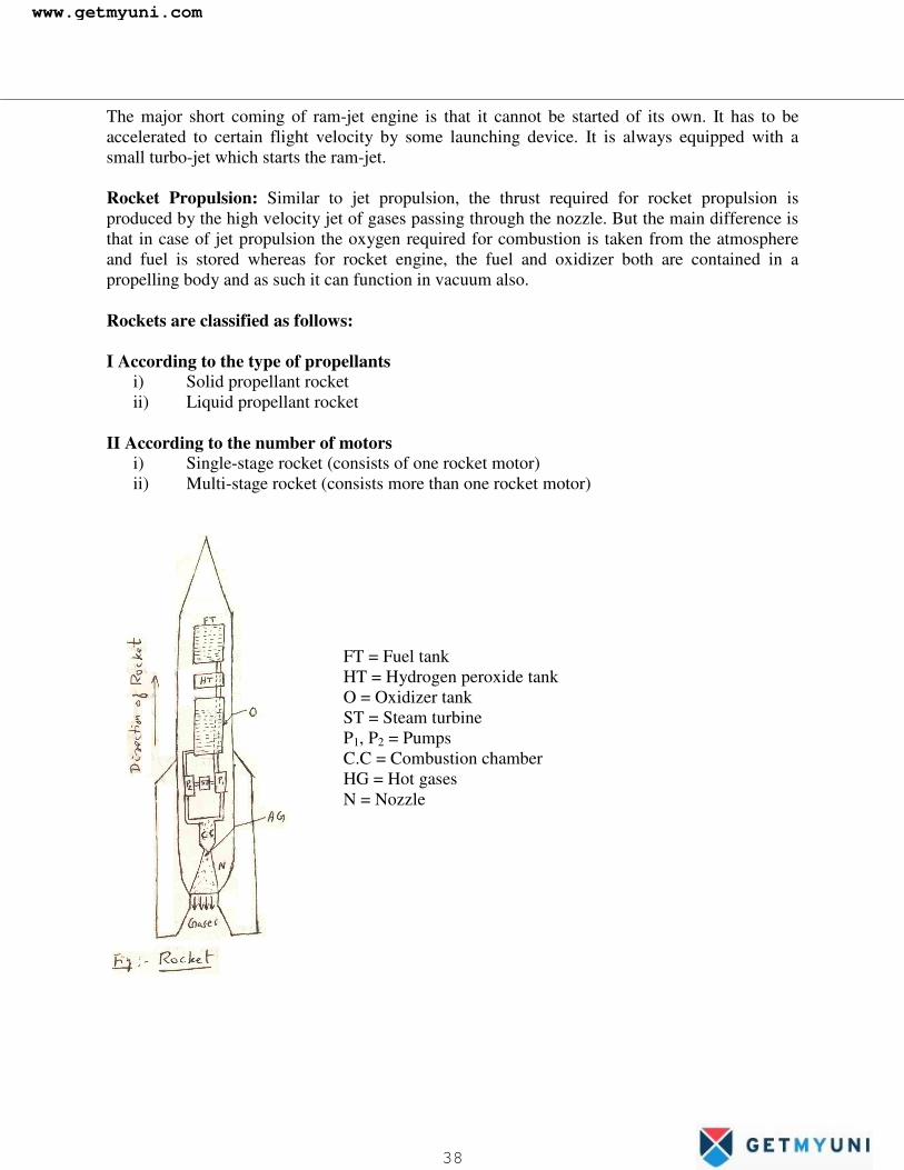
FT = Fuel tank HT = Hydrogen peroxide tank O = Oxidizer tank ST = Steam turbine P1, P2 = Pumps C.C = Combustion chamber HG = Hot gases N = Nozzle�
www.getmyuni.com
38
�
Figure shows a simple type single stage liquid propellant (the fuel and the oxidizer are commonly known as propellants) rocket. It consists of a fuel tank FT, an oxidizer tank O, two pumps P1, P2, a steam turbine ST and a combustion chamber C.C. The fuel tank contains alcohol and oxidizer tank contains liquid oxygen. The fuel and the oxidizer are supplied by the pumps to the combustion chamber where the fuel is ignited by electrical means. The pumps are driven with the help of steam turbine. Here the steam is produced by mixing a very concentrated hydrogen-peroxide with potassium permanganate. The products of combustion are discharged from the combustion chamber through the nozzle N. So the rocket moves in the opposite direction. In some modified forms, this type of rockets may be used in missiles. Uses:
1. Long range artillery 2. Signaling and fire work display 3. Jet assisted take-off 4. For satellites 5. For space ships 6. Research
���
www.getmyuni.com
39