gas turbine data sheet
TRANSCRIPT

7/28/2019 Gas Turbine Data Sheet
http://slidepdf.com/reader/full/gas-turbine-data-sheet 1/59
FICHTNER Volume - III
Project Subject Tender Doc. No. Rev Section
REPUBLIC OF YEMEN TENDER DOCUMENT FOR 1.0
PEC – ME ENGINEERING, PROCUREMENT & 7195-GE-SPC-700-001 BC Sheet No.
400 MW MARIB GTPS – II CONSTRUCTION (EPC) 1
Sec-1 Gas Turbine & auxiliaries_ReBid APM/ME 6/3/07
F O R M T 9 - P R
E V - B
(PEC TENDER NO.: 100/2007)
VOLUME - III
SECTION 1.0
GAS TURBINE & AUXILIARIES

7/28/2019 Gas Turbine Data Sheet
http://slidepdf.com/reader/full/gas-turbine-data-sheet 2/59
FICHTNER Volume - III
Project Subject Tender Doc. No. Rev Section
REPUBLIC OF YEMEN TENDER DOCUMENT FOR 1.0
PEC – ME ENGINEERING, PROCUREMENT & 7195-GE-SPC-700-001 BC Sheet No.
400 MW MARIB GTPS – II CONSTRUCTION (EPC) 2
Sec-1 Gas Turbine & auxiliaries_ReBid APM/ME 6/3/07
F O R M T 9 - P R
E V - B
(PEC TENDER NO.: 100/2007)
Table of Contents
1.0.0 GAS TURBINE & AUXILIARIES SYSTEM...............................................................................3 1.1.0 GENERAL.................................................................................................................................3 1.2.0 SCOPE OF SUPPLY................................................................................................................3 1.3.0 TECHNICAL REQUIREMENTS ...............................................................................................5 1.4.0 MAINTENANCE/INSPECTION REQUIREMENTS OF GTG & AUXILIARIES .....................34 1.5.0 DOCUMENT/DRAWINGS TO BE SUBMITTED ALONG WITH THE BID.............................34 1.6.0 SPECIFIED DESIGN DATA ...................................................................................................36 1.7.0 GUARANTEES, REJECTION ................................................................................................41 1.8.0 TECHNICAL DATA BY THE TENDERER..............................................................................42

7/28/2019 Gas Turbine Data Sheet
http://slidepdf.com/reader/full/gas-turbine-data-sheet 3/59
FICHTNER Volume - III
Project Subject Tender Doc. No. Rev Section
REPUBLIC OF YEMEN TENDER DOCUMENT FOR 1.0
PEC – ME ENGINEERING, PROCUREMENT & 7195-GE-SPC-700-001 BC Sheet No.
400 MW MARIB GTPS – II CONSTRUCTION (EPC) 3
Sec-1 Gas Turbine & auxiliaries_ReBid APM/ME 6/3/07
F O R M T 9 - P R
E V - B
1.0.0 GAS TURBINE & AUXILIARIES SYSTEM
1.1.0 GENERAL
This specification includes the Design, Manufacture, Supply, Erection, Testing &Commissioning of Four (4) no. Gas Turbine & its Auxiliaries system.
The proposed Gas turbine & auxiliaries shall be designed as per the design criteria andmaterial specification given in this specification and shall be new and unused.
If any provision of the specification departs from the Tenderer’s usual construction sufficientlyto materially increase the cost of the equipment without in his opinion, providingcorresponding increase in quality/reliability or if he considers that his standard constructionwould provide better quality/reliability, he shall offer the equipment/system on the basis of hisstandard construction. In case such offer is made, the Tenderer shall state very clearly themerits of his offer and the demerits, (in his opinion) the specified equipment/system has, andthe deviations taken against the specification are to be clearly stated in the “DeviationSchedule” without which it will be considered that the Tenderer complies to the specificationrequirements. However, the Tenderer shall not make any changes on the offered equipmentduring execution.
1.2.0 SCOPE OF SUPPLY
This section sets out the scope of the installations covered by this specification as well asrequired supplies and services, but without excluding other necessary components andservices not mentioned.
1.2.1 Gas turb ine
Each Gas turbine generator unit shall be complete with the following equipment
The air intake system shall be provided with one stage dry system using high efficiency
reverse pulse jet type self cleaning filter system, plenum chamber, silencer, expansion
joints, ducts and supports. The compressed air requirement of intake air filter shall be met
by either GT bleed air or by providing skid mounted air processing unit if required.
Air compressor with anti-surge system
The lube oil system shall be in accordance with manufacturer’s standard
specification/design and normally includes main oil pump, auxiliary oil pump, emergency
oil pump, control oil pump, oil coolers, filters, oil tank (complete with vents, extraction fans,
drain, fill line), controls, interlocks and instrumentation alarms. The system shall bedesigned to cater to the GT requirement during normal operation/ emergency
trip/shutdown and coast off as well as during start-up condition.
Inlet guide vane system
Fuel combustion system complete with ignition system with burners designed for NOx
abatement meeting emission norms as indicated in Vol-II, Cl. 16.2.5.
The cooling water for the GT lube oil cooler, generator air cooler and control oil cooler (if
required) shall be catered by CCW system.
Starting system consisting of SFC or starting motor with auxiliaries and shut down system.
Accessory drive gearbox
Exhaust frame blower & motors

7/28/2019 Gas Turbine Data Sheet
http://slidepdf.com/reader/full/gas-turbine-data-sheet 4/59
FICHTNER Volume - III
Project Subject Tender Doc. No. Rev Section
REPUBLIC OF YEMEN TENDER DOCUMENT FOR 1.0
PEC – ME ENGINEERING, PROCUREMENT & 7195-GE-SPC-700-001 BC Sheet No.
400 MW MARIB GTPS – II CONSTRUCTION (EPC) 4
Sec-1 Gas Turbine & auxiliaries_ReBid APM/ME 6/3/07
F O R M T 9 - P R
E V - B
Atomising air pre-cooler, Atomising air manifold, with necessary controls. All combustion
and atomizing air to be taken from GT compressor. The main compressors shall also
provide full pressure boost at initial start.
Mounting System
Barring facilities as per Manufacturers own design comprising of either Turning Gear
system with an a.c. drive, or an Auxiliary Hydraulic Ratchet System. Provision of manually
turning the turbine generator shall be available.
One (1) number on-line / off line compressor water wash system comprising of detergent &
DM water tank, heaters, motor driven wash pump, motor driven detergent pump,
interconnecting SS piping, etc. The water wash system shall be skid mounted & shall be
provided with a weatherproof enclosure.
Drain system with dirty oil drain collection tank, associated pipe work and transfer pump.
Bolt tightening system either hydraulic or electric heating element type.
Turbine shell & exhaust frame cooling system
Machinery equipment unit enclosures with insulation and ventilation, interior lighting etc
suitable for outdoor installation.
Integral Fire Detection & Protection System for the turbine enclosures.
Closed Cooling water system interconnecting piping, valves etc.,
Gas Turbine exhaust gas ducts with expansion joints, silencer and exhaust stack of 30 m
minimum height.
1.2.2 Common equipment and services
- All controls, measuring and monitoring equipment, to an extent at least in accordancewith the corresponding descriptions of section 9.0 of Volume V and additionalinstrumentation necessary for matching to specific designs of equipment and units.
- Necessary drain tanks, interconnection piping instruments, controls etc.
- All necessary pipe work fittings, expansion joints, valves, automatic actuators, safetydevices, fastenings, etc.
- Foundations anchor tools, spring guides, embedded parts, base frame, bed plates, soleplates, shims, packers, supports, etc. for all equipment.
- All necessary insulation as required in Section 7.7 of Vol. IV.
- All necessary painting, corrosion protection and preservation measures as required inSection 7.6 of Vol. IV.
- Complete detailed labeling of all installations as required in Section 13.0 of Vol. II
- Documentation according to Section 12.0 of Vol. II
- All necessary service platforms, stairs, ladders, for the complete Gas turbine generator area, together with all auxiliary equipment.
- All necessary noise prevention measures as required in `General TechnicalSpecification’.
- All necessary couplings and coupling guards

7/28/2019 Gas Turbine Data Sheet
http://slidepdf.com/reader/full/gas-turbine-data-sheet 5/59
FICHTNER Volume - III
Project Subject Tender Doc. No. Rev Section
REPUBLIC OF YEMEN TENDER DOCUMENT FOR 1.0
PEC – ME ENGINEERING, PROCUREMENT & 7195-GE-SPC-700-001 BC Sheet No.
400 MW MARIB GTPS – II CONSTRUCTION (EPC) 5
Sec-1 Gas Turbine & auxiliaries_ReBid APM/ME 6/3/07
F O R M T 9 - P R
E V - B
- All necessary venting, draining and emptying equipment
- All necessary safety measures
- One set of special tools, tackles and equipment as per section 11.0 of Vol. II
- Complete electrical system including drive motors suitable for area specified, controlpanel, local push button stations, transformer rectifier set, power & control cables, cablingcomplete with supports, cable trays, glands, lugs, for the successful operation of theplant. The electrical system shall conform to the requirements specified in Section 8.0 of Vol. V
- Spare parts according to section 10.0 of Vol. II
- All consumables as per section 3.0 of Vol. II
.
- Tapping points complete with isolation and all necessary instruments for performanceguarantee testing.
- All standard equipment and accessories normally included in the supply schedule but notseparately listed.
1.3.0 TECHNICAL REQUIREMENTS
1.3.1 General
The requirements indicated in this specification is for each Gas Turbine Generator unlessotherwise exclusively specified.
The gas turbine shall be of heavy duty, industrial type suitable for outdoor installation with asound attenuation, weatherproof enclosure, directly coupled to a 50 Hz generator.
The alternating current electrical generator shall be directly coupled to the gas turbine.
The gas turbine shall be capable of firing both Natural Gas and Distillate Oil. The NaturalGas will be the primary fuel and Distillate oil will be the standby fuel.
All major components namely the gas turbine, auxiliary components, generator and other major critical systems included in the gas turbine package shall be required to undergo
acceptance test-run at the manufacturers works prior to delivery at site.
The Tenderer shall in the design of essential auxiliary systems refer to appropriate electricalspecification to ensure that the source of power supplies is consistent with the philosophy of providing a reliable AC supply and safe DC sources to ensure safe start-up operation andshutdown of the unit under any conditions.
The Tenderer shall design the gas turbine proper and its auxiliaries using his goodengineering practice and proven experience, in order to obtain good and reliable equipmenthaving superior performance. No prototype equipment or components shall be used. Thetechnical lifetime of gas turbine plant shall not be less than 25 years
All accessories, cables, piping, protection and safety equipment and auxiliaries normally
belonging to a package unit required for safe and continuous operation, even if notspecifically mentioned shall be included.

7/28/2019 Gas Turbine Data Sheet
http://slidepdf.com/reader/full/gas-turbine-data-sheet 6/59
FICHTNER Volume - III
Project Subject Tender Doc. No. Rev Section
REPUBLIC OF YEMEN TENDER DOCUMENT FOR 1.0
PEC – ME ENGINEERING, PROCUREMENT & 7195-GE-SPC-700-001 BC Sheet No.
400 MW MARIB GTPS – II CONSTRUCTION (EPC) 6
Sec-1 Gas Turbine & auxiliaries_ReBid APM/ME 6/3/07
F O R M T 9 - P R
E V - B
The Tenderer shall offer a plant complete with all parts and details, functional and operationalunder Site conditions, designed and manufactured with good engineering practice and tointernational standards.
The gas turbine shall have minimum number of bearings and shall be located on a steelframe with adequate steel structures and concrete foundations and all bearings to be easilyaccessible.
Accessibi li ty and Ease of Maintenance
Considerable importance will be placed on the ease with which maintenance and servicing
can be carried out on all equipment. It shall be possible to remove and replace such sections
of the enclosures as are necessary to undertake maintenance with the minimum of
disturbance to other equipment. The Contractor shall therefore provide comprehensive and
fully detailed information on this subject suitably illustrated with diagrams and drawings.
In particular, the recommended procedures for carrying out the following operations shall be
described:
(a) removal of the turbine/compressor rotor and generator rotor
(b) replacement of all combustion chamber linings
(c) replacement of air intake filters elements
(d) removal of all casings
All lifting equipment and runway beams necessary to remove the equipment for maintenance shall be provided.
1.3.2 Foundation
The gas turbine, generator and all directly coupled auxiliaries shall be installed on onecommon foundation.
1.3.3 Air compressor
The gas turbine air compressor shall be sufficiently flexible aerodynamically to permit normaloperation of the turbine generator unit without any tendency to surge such that it isunconditionally stable at all loads, during load changes, during run-up and shut-down, and
overspeed. The rotor is to be statically and dynamically balanced and overspeed tested atthe factory.
In order to enhance the high efficiency at part load in simple cycle and combined cycle mode,variable geometry inlet guide vane shall be installed as part of the gas turbine maincomponent.
If any device is provided for control of compressor surge and/or exhaust temperature controlby virtue of air flow control, they shall be of proven design and independent of externalsupplies. Full details of the system shall be stated in the Bid. Performance details of thecompressor shall be given to indicate the margin provided against surge under operatingconditions.
Tap-off's shall be provided to supply air required for sealing of gas turbine glands, bearingsand for cooling of the combustor nozzles & turbine blades, cleaning of air filters.

7/28/2019 Gas Turbine Data Sheet
http://slidepdf.com/reader/full/gas-turbine-data-sheet 7/59
FICHTNER Volume - III
Project Subject Tender Doc. No. Rev Section
REPUBLIC OF YEMEN TENDER DOCUMENT FOR 1.0
PEC – ME ENGINEERING, PROCUREMENT & 7195-GE-SPC-700-001 BC Sheet No.
400 MW MARIB GTPS – II CONSTRUCTION (EPC) 7
Sec-1 Gas Turbine & auxiliaries_ReBid APM/ME 6/3/07
F O R M T 9 - P R
E V - B
The materials and coating of the compressor stationary and rotating blades shall be chosento be suitable for continuous operation in the site climatic conditions. The air path of thecompressor including rotor, blades, and housing shall be protected by suitable and adequatecoating. The materials and coating used shall be stated in the Bid.
Provision shall be made for accurately measuring the mean compressor delivery temperatureand static delivery pressure with test instruments. Borescope holes shall be located in thecompressor section to facilitate usual inspection.
1.3.4 Combust ion System
The gas turbine units shall be dual fuel and designed to fire the specified gas fuel or liquid fuel
oils as specified. Gas Turbine Generators are to be operated with natural gas as primary fueland distillate oil as back-up fuel.
The design of the combustion system shall be such that an even temperature distribution isprovided at the turbine inlet.
The normal and maximum limits of temperature scatter (spread) at the turbine inlet and itscontrol shall be stated in the Bid. The corresponding temperature limits shall be given at thenormal temperature measuring points.
The burners shall be of the 'smokeless' design capable of efficient atomization and stablecombustion at all loads and to meet current allowable emission limits.
Combustion efficiency shall be sufficiently high to ensure the exhaust emissions compliedwith the requirement of "Specified Design Data"
Tenderer shall not elevate the firing temperature solely for the purpose of obtaining higher efficiency, without due consideration of exhaust emission limitation and long operating life of 'hot gas path' components.
The exhaust gas shall be (during transient as well as steady state operation including full speed
no load operation and change over from one to another fuel) as clear as possible, whereby the
degree of smoke intensity, specified by smoke spot number shall not exceed the following limits
:
Bacharach Smoke Spot No. 1(Definitions see ASTM D 156 - 65)
A reliable flame supervisory system shall be provided to detect the presence of a flame in thecombustion chamber based upon two out of three redundancy system. This system inprinciple shall employ three sensing elements through three separate channels, with atleasttwo channels detecting the absence of the flame to trigger the trip. Any one channel shalldetect absence of the flame and shall initiate an alarm for immediate action.
If the gas turbine is having more than one combustion chamber without any inter-connection,the redundancy system shall be fitted to each chamber. Where multi-chambers are cross-connected the three supervisory elements shall be fitted to different combustion chambers.Inspection windows, or the facility for inspection equipment shall be provided and the method
stated in the Bid.

7/28/2019 Gas Turbine Data Sheet
http://slidepdf.com/reader/full/gas-turbine-data-sheet 8/59

7/28/2019 Gas Turbine Data Sheet
http://slidepdf.com/reader/full/gas-turbine-data-sheet 9/59
FICHTNER Volume - III
Project Subject Tender Doc. No. Rev Section
REPUBLIC OF YEMEN TENDER DOCUMENT FOR 1.0
PEC – ME ENGINEERING, PROCUREMENT & 7195-GE-SPC-700-001 BC Sheet No.
400 MW MARIB GTPS – II CONSTRUCTION (EPC) 9
Sec-1 Gas Turbine & auxiliaries_ReBid APM/ME 6/3/07
F O R M T 9 - P R
E V - B
arrangement. If any external cooling pipes are used adequate drainage arrangements shallbe installed where necessary.
The turbine casings, moving and stationary blading shall be designed to withstand themaximum temperature scatter which may occur in service under adverse combustionconditions with the machine running at the design maximum mean turbine inlet temperature.
The casings and blading shall withstand, without premature failure, the thermal shockassociated with repeated starting, loading and rapid load changes. Any limitations on plantoffered shall be stated in the Bid.
All the parting plane bolts in the gas turbine casings shall be designed for opening withhydraulic tools. Design with heating shall not be allowed.
Where jacking bolts and jacking guides are recommended by the gas turbine manufacturer for use in lifting/removing casing sections then this equipment shall be provided under this
contract.
The factor of safety for the turbine disc and blades based on the disc and blade stressesapplicable to an overspeed of 20% in the fully heat soaked condition at the design full loadshall be stated in the Bid.
The stationary and rotating blades shall be coated with appropriate high temperatureprotective layer, which shall reduce the attack of corrosive gases and products of combustion.The Tenderer shall indicate the number of stages which are coated and shall describe thetype of protective layer (coat) or other protective means.
Inspection equipment and facilities including suitable plugged openings shall be provided toexamine the compressor-turbine stationary and rotating blading with minimum disassembly
and without the need to open the casing or lifting the rotor. The internal inspection facilitiesand tools/equipment shall be stated in the Bid.
The materials of construction for the rotors and stationary and moving blades shall be statedin the Bid.
Antisieze compound shall be used on initial build of all nuts, bolts, studs and location dowelsetc.,
All instrumentation required to measure the gas turbine exhaust temperatures shall beprovided and shall be capable of identifying any imbalance in temperature distribution.Thermocouples including the junction box shall be suitably located where they will notmalfunction and to permit easy accessibility by the maintenance personnel.
1.3.6 Compressor Blade Cleaning Equipment
Suitable and proven equipment for on-line and off-line blade cleaning shall be provided for thecompressor blading without the necessity for opening up or dismantling any part of themachine. It shall be the Tenderer's responsibility to devise a suitable cleaning technique tosuit the anticipated type of fouling which will be encountered at Site. If, during the warrantyperiod, it is found that the cleaning systems supplied are ineffective, the Tenderer shall makeany necessary modifications or change the method of cleaning at no extra charge.
The cleaning procedures provided shall be operable only by manual initiation.
Sufficient storage tanks or bins to hold the cleaning medium to achieve one completecleaning cycle shall be provided. Storage tanks or bins shall be located to be easily

7/28/2019 Gas Turbine Data Sheet
http://slidepdf.com/reader/full/gas-turbine-data-sheet 10/59
FICHTNER Volume - III
Project Subject Tender Doc. No. Rev Section
REPUBLIC OF YEMEN TENDER DOCUMENT FOR 1.0
PEC – ME ENGINEERING, PROCUREMENT & 7195-GE-SPC-700-001 BC Sheet No.
400 MW MARIB GTPS – II CONSTRUCTION (EPC) 10
Sec-1 Gas Turbine & auxiliaries_ReBid APM/ME 6/3/07
F O R M T 9 - P R
E V - B
accessible for topping up the cleaning medium. The storage tanks, heater, piping, etc shall beof stainless steel construction.
The Tenderer shall supply cleaning medium upto one (1) month after taking over of the plantin well packed drums to allow proper storage. The Tenderer shall state if the cleaningmedium is locally available.
The margin of performance deterioration that the machine will accept before a cleaning cycleis deemed necessary shall be stated in the Bid. The method used to ascertain this marginshall be stated in the Bid (e.g compressor delivery pressure, power output with respect toturbine exhaust temperature).
The effluent formed during cleaning shall be piped to the nearby sump from where it shall besuitably disposed.
Accessory Gear (Wherever Applicable)
If any accessory gear drive is provided to transmit power from the main turbine rotor toturbine accessories, the gear box design shall comply with requirements of API 613 or equivalent recognised National / International Standard and to the highest short-circuitloading.
Removable guards and shields shall be provided to protect personnel from the accessorygear and rotating shafts and warming signs installed.
1.3.7 Mounting System
The mounting system of the gas turbine casing onto the foundation shall take full account of vibration and thermal expansion of the unit.
Details of the method used to locate the fixed point of the turbine casing in relation to the rotor thrust bearing and the provision for accommodating thermal expansion of the casing andmaintaining rotor alignment without producing detrimental stresses shall be stated in the Bid.
If lubrication or gasket or cooling system is required between moving surfaces, the materialsof the contacting surfaces and the method of lubrication, the gasket type, and the coolingsystem shall be stated in the Bid.
If any of the turbine generator supports require cooling, the equipment and the coolingarrangement and means of monitoring shall be described in the Bid.
Care shall be taken to ensure that radiant heat from the turbine exhaust casing does notadversely affect the mechanical integrity of the concrete foundation structure. The turbineshell & exhaust frame compartment shall be cooled using two nos. 100% capacity blowers, if required.
1.3.8 Piping
The gas turbine generator unit shall be provided with a complete system of high quality, non-corroding and heat resistant piping integral to, or between, components furnished by theTenderer.
Piping shall include all high point vents, low point drains, instrument piping, insulation,hangers, and other piping accessories required for a complete system. All piping shall befactory mounted on the unit to the extent possible.

7/28/2019 Gas Turbine Data Sheet
http://slidepdf.com/reader/full/gas-turbine-data-sheet 11/59
FICHTNER Volume - III
Project Subject Tender Doc. No. Rev Section
REPUBLIC OF YEMEN TENDER DOCUMENT FOR 1.0
PEC – ME ENGINEERING, PROCUREMENT & 7195-GE-SPC-700-001 BC Sheet No.
400 MW MARIB GTPS – II CONSTRUCTION (EPC) 11
Sec-1 Gas Turbine & auxiliaries_ReBid APM/ME 6/3/07
F O R M T 9 - P R
E V - B
All piping shall be routed so as to be within the confines of the gas turbine generator enclosure whenever possible. A minimum of 2,500 mm head room clearance is desired over
walkways and access areas. All flanges shall be easily accessible and pipes divided intomanageable portions for handling.
All piping shall be neatly arranged to be as inconspicuous as possible and shall offer minimalobstruction while being easily supported and drained.
1.3.9 Bearings and Glands
Hydrodynamic horizontally split radial bearings of the precision bore sleeve or multi-pad typewith steel backed white metal replaceable sleeves or pads shall be provided for each mainshaft bearing. The bearings shall be arranged so that they are adjustable and readily
accessible and the lower halves can be removed and replaced without lifting the rotor morethan the minimum allowable internal vertical clearance.
The bearing design shall suppress hydrodynamic instabilities and also provide sufficientdamping to limit shaft vibrations. Vibration sensors shall be provided for each bearing.
Suitable provision shall be provided for each bearing so that wear on the bearings can bereadily ascertained. These equipments shall be finally fitted and stamped on site after thealignment of the rotors has been proved. The design and material specification of the bridgegauges shall prevent alterations in the gauge reading with variations in temperature.
1.3.10 Thrust Bearing
The rotors shall be provided with a thrust bearing of the Mitchell or Kingsbury or equivalenttilting multi-pad type which shall have identified main and reverse thrust faces sized towithstand all normal and abnormal thrust in either direction that can be experienced in serviceunder the most adverse conditions. The thrust collar may be integral with the shaft or separate and replaceable. Integral collars shall be provided with a minimum of 3mmadditional stock on each thrust face for remachining should the collar be damaged.
Vibration sensors shall be provided for the thrust bearing. Means shall be provided to indicateexcessive axial movement due to a failure of a thrust bearing, preferably combined withfacilities to measure thrust movement on load. This is to be in accordance withmanufacturer's standard design.
1.3.11 Temperature Supervision
The Tenderer shall install duplex thermocouple in the white metal of each bearing of the gasturbine and generator and also within each pad of the thrust bearing. This thermocouple shallbe positioned to ensure a quick response in detecting abnormal changes in metaltemperature. Any limitations on operating conditions, such as motoring the compressor andturbine generator, and the duration of transients shall be stated in the Bid.
Each of the above radial bearing and thrust bearings shall be provided with a resistancetemperature device to monitor oil drain temperatures which shall actuate both an alarm andtrip on high oil temperature. Thermocouple will be acceptable in place of resistancetemperature devices.
1.3.12 Glands

7/28/2019 Gas Turbine Data Sheet
http://slidepdf.com/reader/full/gas-turbine-data-sheet 12/59
FICHTNER Volume - III
Project Subject Tender Doc. No. Rev Section
REPUBLIC OF YEMEN TENDER DOCUMENT FOR 1.0
PEC – ME ENGINEERING, PROCUREMENT & 7195-GE-SPC-700-001 BC Sheet No.
400 MW MARIB GTPS – II CONSTRUCTION (EPC) 12
Sec-1 Gas Turbine & auxiliaries_ReBid APM/ME 6/3/07
F O R M T 9 - P R
E V - B
Arrangements shall be made to preclude any leakage of gas blowing from the glands into theturbine enclosure or turbine hall. Renewable, metallic sealing rings shall be provided at allinternal close clearance points between the rotor and stationary parts to minimize leakage of
air, gas fuel combustion products and oil from the casings or housings.
1.3.13 Shaft Currents-Earthing
Provision shall be made for the prevention of damage to bearings, oil pump drives etc., byany shaft currents, which may be produced. Bearings and any associated pipes shall beinsulated from ground and earthing brushes provided, and care shall be taken so that noextraneous earth paths, e.g through metallic cable sheaths, etc., shall short circuit theinsulation.
1.3.14 Condensation and Corrosion
The Tenderer shall state the precautions and necessary procedures to protect the
compressor and turbine components from corrosion and fouling when the plant is required tobe off-service for long periods of standstill. Any necessary equipment such as heaters, hotair blower or other devices to maintain the plant especially the internal parts under warm anddry condition shall be provided.
1.3.15 Noise Limi ts
The noise emanating from each gas turbine generator shall not exceed a limit of 85 dBA at adistance of 1.0 m from the outline of the equipment.
If the noise level requirements applicable to each gas turbine generator cannot be achieved,then suitable acoustic hoods/enclosures or treatment shall be provided and installed witheach gas turbine generator unit and its machine hall.
The use of earmuffs or earplugs are not considered as noise mitigative device. The Tenderer shall however provide 50 sets of approved earmuffs.
1.3.16 Vibration, Balancing and Critical Speeds
Vibration monitoring equipment of the velocity type shall be provided for each main shaft
bearing which shall indicate the severity of vibration expressed as an rms velocity in mm/s
Vibration detectors should be mounted vertically or at an angle recommended by the
manufacturer.
Individual shafts, discs and couplings shall be dynamically balanced before assembly so that the
severity of vibration of the complete unit during operation at any load is within the range of 2.8 to7.1 mm/s rms velocity according to ISO Standards.
Any lateral or torsional critical speed of the total combined shaft system including thegenerator and exciters (if any) should be at least 20% above or below the normal range of operating speeds However, if the critical speed(s) as calculated or revealed on test does notmeet the specified separation margin, the response of the rotating assembly to the criticalspeed(s) in question shall be demonstrated and certified in accordance with API Standards.
Care shall be taken in the design of the stationary parts of the plant to ensure that no staticpart is excited or touched/rubbed by vibration transmitted from the rotating parts.
1.3.17 Lube Oil System
General

7/28/2019 Gas Turbine Data Sheet
http://slidepdf.com/reader/full/gas-turbine-data-sheet 13/59
FICHTNER Volume - III
Project Subject Tender Doc. No. Rev Section
REPUBLIC OF YEMEN TENDER DOCUMENT FOR 1.0
PEC – ME ENGINEERING, PROCUREMENT & 7195-GE-SPC-700-001 BC Sheet No.
400 MW MARIB GTPS – II CONSTRUCTION (EPC) 13
Sec-1 Gas Turbine & auxiliaries_ReBid APM/ME 6/3/07
F O R M T 9 - P R
E V - B
A complete lube oil system, shall be provided for the turbine generator unit and shall be fullyintegrated with any associated relay oil, governing oil and dirty oil drains system supplied.The system shall have sufficient capacity to accommodate the requirements of the above
systems with additional margin.
The specification of the lube oil shall be such that they can be procured from local sources.
Lube oil shall be of the appropriate grade specific to heavy duty industrial type gas turbineapplication. The Tenderer shall state in the Bid the equivalent type of lube oil from all leadingbrands.
The system shall include sufficient full standby equipment to allow any item of equipmentwithin the oil system to be taken out of service for maintenance without having to shut-downthe unit and also without restricting in any way the normal full output operation of the gasturbine unit.
The capacity of the system and duty of the main oil pumps shall be such that the number of complete changes of oil in the tank per hour does not exceed eight.
Local and remote alarms shall indicate the operation of the a.c and d.c pumps or loss of oilsupply during the rundown period.
Pressure accumulator shall be included in the oil system in order to avoid an unacceptablepressure drop during starting of the standby oil pump, and also during the changeover of filters.
If positive displacement pumps are used, pressure relief valves shall be provided in for the fullsupply quantity.
The oil temperature rise through each bearing shall not exceed 30°C. The maximum bearingoil drain temperature from each bearing shall not exceed 90°C and the maximum bearingmetal temperature shall not exceed 115°C.
The oil system shall be designed to prevent the possibility of fire due to the leakage of vaporsor fluids from the systems onto high temperature parts as a result of physical damage or piping failure. As a minimum, this shall include the following.
a Double pipe or outer housings designed to retain leaking fluid and to resist physicaldamage.
b Suitable drains provided from the housings or double pipe to the lube oil tank.c. Lube oil pipings located away from cable trays.d. Oil piping routed around or below high temperature components where practical. Such
components to be additionally insulated and heat shielded.
Lube Oil Pumps
The pumps shall comply with the General Technical Requirements. Starting and stopping of the motor driven pumps shall be normally automatic, but manual override facilities shall beincorporated.
Interlocks shall be provided to prevent starting of the gas turbine units in the absence of adequate lube oil pressure.
i. Main Lube Oil Pump
The Main Lube Oil Pump shall be mechanically driven from the turbine shaft or A.C. motor driven. The pump shall be of centrifugal type/ positive displacement gear type and shall be

7/28/2019 Gas Turbine Data Sheet
http://slidepdf.com/reader/full/gas-turbine-data-sheet 14/59
FICHTNER Volume - III
Project Subject Tender Doc. No. Rev Section
REPUBLIC OF YEMEN TENDER DOCUMENT FOR 1.0
PEC – ME ENGINEERING, PROCUREMENT & 7195-GE-SPC-700-001 BC Sheet No.
400 MW MARIB GTPS – II CONSTRUCTION (EPC) 14
Sec-1 Gas Turbine & auxiliaries_ReBid APM/ME 6/3/07
F O R M T 9 - P R
E V - B
rated at 100% duty, sufficient to supply all oil requirements for the lubricating system asappropriate under all conditions of load.
Provision shall be made for automatic priming of the pump and for the maintenance of thesuction head.
ii Auxiliary Lube Oil Pump
The Auxiliary Oil Pump shall be A.C motor driven and preferably located integral with theLubricating Oil Tank. This pump shall be rated at 100% duty, as for the Main Lube Oil Pumpand shall be self-priming. The pump shall be capable of allowing the turbine generator to
operate under all conditions of load and speed with the Main Lube Oil Pump out of serviceand shall be available primarily for starting up of the turbine generator unit and for automaticstandby upon rundown of the unit. The Auxiliary Lube Oil Pump stop and start initiation shallbe accommodated by the provision of pressure switches to be supplied under this Contract.
The system shall be designed to ensure that the operation of the Auxiliary Lube Oil Pumpautomatic start sequence does not allow the oil pressure to drop to a level that would trip theturbine generator unit.
iii . Emergency Lube Oil Pump
One emergency rundown D.C driven pump shall be provided, preferably mounted integralwith the Lubricating Oil Tank, for supply of sufficient lubricating oil to the bearings when the
unit is running down after a trip. The pump shall come into operation automatically on low oilpressure or loss of A.C supplies. The D.C emergency rundown oil pump shall be arranged toenable the turbine-generator to be brought to rest without damage under mishap conditionssuch as the total loss of A.C supplies.
iv. Hydraulic oil pumps (If required)
2x100% Hydraulic oil pump shall be of AC motor driven capable of supplying control oilrequirement. The constructional and operating features shall be same as that of Auxiliarylube oil pump described above.
v. Jacking Oil Pump
1x100% AC motor driven positive displacement pump shall be provided. Separate supplies toeach bearing shall be provided so that the rotors may be lifted in their bearings to reduce thetorque load on the barring gear or if hand barring is operated.
Lubricating Oil Tank
The lubricating oil storage tank associated with the gas turbine shall be of weldedconstruction of high quality carbon steel plate and its capacity shall provide adequateresidence time under normal operating conditions. The tank shall be positioned so that thereis adequate gravity drainage from the system to the tank and from the tank to thetransfer/drains tank.
Suitable removable fine mesh strainers shall be provided at all inlets of the tank andinspection of the strainers shall be possible with the machine running.

7/28/2019 Gas Turbine Data Sheet
http://slidepdf.com/reader/full/gas-turbine-data-sheet 15/59
FICHTNER Volume - III
Project Subject Tender Doc. No. Rev Section
REPUBLIC OF YEMEN TENDER DOCUMENT FOR 1.0
PEC – ME ENGINEERING, PROCUREMENT & 7195-GE-SPC-700-001 BC Sheet No.
400 MW MARIB GTPS – II CONSTRUCTION (EPC) 15
Sec-1 Gas Turbine & auxiliaries_ReBid APM/ME 6/3/07
F O R M T 9 - P R
E V - B
The oil tank shall be vented by two 100% duty A.C motor driven vapor extractor fans . Eachvapor extractor impeller and casing shall be made of materials that will not cause sparkingshould contact occur. The fan motor shall be of flame-proof type.
Vent shall be taken outside the building or enclosure preferable to above roof level anddirected away from the building and gas turbine air filtration plant. Any horizontal vent pipeshall have a natural drainage back to the tank and suitable drainage of oil build-up shall beprovided at the discharge from the extractors and elsewhere in the vent system as necessary.
Vent shall be provided with demister to prevent oil spray into the atmosphere. The demister shall be designed to limit lubricating oil emissions to minimum.
Internally, the tank shall be baffled to ensure adequate deaeration of the oil. Apart frombaffles there should be no equipment located within the tank. Sufficient bolted covers shallbe provided for access by maintenance personnel to each compartment for inspection andcleaning purposes. Access rungs shall be provided to permit safe and easy access. All
loose and fixed covers on the top surface of the tank shall be located on raised rims of atleast25 mm above tank surface and gasketed with locating pins.
In order to avoid welding at site, which could damage the tank internal painting, all necessarypipe connections etc., shall consist of flange stub connections welded on the tank. In no caseshall the tank be drilled and studs or bolts fitted from the inside of the tank.
The main oil suction point (the bottom of the bore of the connection) shall not be closer than150 mm from the base of the tank.
The tank shall be provided with a full complement of isolating and drain valves with a cap andalso, with a filling point fitted with a cover. There shall be convenient coupling connectionswith isolating valves for the portable oil purifier unit.
The base of the tank shall slope to a common point to facilitate complete draining of the tankand an accessible lockable drain valve shall be provided and fitted directly against the tankfor this purpose. Piping shall be provided from the drain valve to a suitable point where the oilcan be run into the dirty oil storage tank or dirty drain tank.
Sampling points including the necessary fittings shall be provided at suitable locations on theoil tank.
Switches shall be provided for initiating low oil level alarms. The switches shall be of the typewhich are completely sealed at the mounting point, such that leakage of oil through the switchis impossible. Two level switches shall be provided which shall be used to initiate alarmswhen the oil level is low and the lower one shall be used to initiate a trip of the turbine. A
visual oil level gauge shall also be provided and shall be capable of being read local to thetank.
The tank shall be painted internally with a suitable oil, heat and corrosion resistant paint asper the requirements of the painting specification. The tank shall also be painted externally.
Oil Filters
All oil filters shall be of the duplex type and shall be capable of change over during operationwithout interruption. The changeover valves shall be interlocked or arranged so that it is notpossible to inadvertently cut off the supply of oil to the unit. A differential pressure gaugealong with Differential Pressure Switch shall be provided across each filter. Adequateprovision shall be made for draining, venting and cleaning the section of filter housingundergoing maintenance. The drain and vent pipes shall be connected to the dirty oil drainssystem.

7/28/2019 Gas Turbine Data Sheet
http://slidepdf.com/reader/full/gas-turbine-data-sheet 16/59
FICHTNER Volume - III
Project Subject Tender Doc. No. Rev Section
REPUBLIC OF YEMEN TENDER DOCUMENT FOR 1.0
PEC – ME ENGINEERING, PROCUREMENT & 7195-GE-SPC-700-001 BC Sheet No.
400 MW MARIB GTPS – II CONSTRUCTION (EPC) 16
Sec-1 Gas Turbine & auxiliaries_ReBid APM/ME 6/3/07
F O R M T 9 - P R
E V - B
Bypass relief valves shall not be fitted across filters. Each filter shall be designed towithstand the maximum differential pressure that should occur in the oil system.
Filters of 5 microns or smaller shall be provided for lube oil, whereas filters of 0.5 micron shallbe provided for the control oil systems.
Lubricating oil pressure shall be sensed after the filter for the purpose of cutting in and out of the standby and emergency pumps and for initiating a low oil pressure alarm at one level,followed by a trip initiation at a lower level.
The lubricating oil filters shall be positioned as close as possible to the feed points of themachine.
If the control oil is filtered separately from the main oil, duplicate 100% duty filters which willallow on-load cleaning and change over from one filter to the other without interruption to full
oil flow shall be provided.
Portable / fixed, lube oil purifiers shall be provided as per manufacturer's standards.
Lubricating Oil Coolers
Two 100 % duty oil coolers shall be provided for the Gas Turbine Generator unit.
The design, size and change-over facility of the coolers shall be so arranged that cleaning of any one of the cooler unit is possible during peak load operation of the gas turbine generator.
The design shall be based upon tubular heat exchanger with closed circuit cooling water passing through the tubes and the lubricating oil through the shell and over the tubes. The
cooling medium (DM water) in the closed loop system will be in turn cooled by forced air in aradiator.
The materials of construction of the oil/water cooler tubes and the tube sheet shall beadmiralty brass. The tubes shall be straight and not of the hair-pin or coil type.
The tube sheet shall have provision for differential expansion between the cooler shell andthe tube bundle. The cooler shells shall be constructed of appropriate grade steel and shallbe fitted with an air vent at the highest point on the shell and a drain valve with cap..
The cooler waterboxes shall be fabricated from appropriate grade stainless steel, the highestpoint of each waterbox supplied with a connection for priming and another fitted with anisolating valve for use with siphonic system vents. An expansion relief valve, and all
appropriate drain and air release valves, shall be provided with pipework leading to thenearest station perimeter drain.
The cooler shall be supported such that the waterboxes can be removed without difficulty andadequate access to the tube plates is possible.
The arrangement of waterbox connections shall be such that tubes can be cleaned withoutbreaking any oil or water pipe joints and withdrawal of the tube bundle should be possible.Cooler top covers shall be fitted with adequate tube bundle withdrawal facilities and liftinglugs and jigs shall also be provided for lifting of the tube bundle into place.
The coolers shall be provided on the oil side with an automatic pressure relief bypass.
It is preferred that the oil pressure in the coolers should be greater than the cooling water pressure under all running conditions.

7/28/2019 Gas Turbine Data Sheet
http://slidepdf.com/reader/full/gas-turbine-data-sheet 17/59
FICHTNER Volume - III
Project Subject Tender Doc. No. Rev Section
REPUBLIC OF YEMEN TENDER DOCUMENT FOR 1.0
PEC – ME ENGINEERING, PROCUREMENT & 7195-GE-SPC-700-001 BC Sheet No.
400 MW MARIB GTPS – II CONSTRUCTION (EPC) 17
Sec-1 Gas Turbine & auxiliaries_ReBid APM/ME 6/3/07
F O R M T 9 - P R
E V - B
A pressure monitoring arrangement shall be provided for each oil cooler to initiate an alarm inthe event of the water pressure exceeding the oil pressure. Onload testing of these alarm
initiating devices shall be possible.
Closed Circuit Cooling Water System (CCCWS)
For each gas turbine generator unit, one closed circuit cooling system shall be providedcomplete and fully functional in itself.
Closed loop cooling system shall be provided with Air Fin Cooler with 25% margin on cooling
capacity & 2x100% cooling water pumps.
Inhibitors, which are used in cooling water to reduce corrosion, must be free from poisonous
components like chromates.
One Expansion tank alongwith level indicators, level switches, float valves, tank filling line will be
provided in each unit Air fin cooling system.
Closed cooling water will be Deminearalised water. Cooling water make up to the expansion
tank shall be from plant DM water system.
Material of cooler pipes shall be selected in view of possible corrosion and is subject to approval
by the Engineer.
The design shall incorporate adequate equipment for taking water samples for testing to
introduce inhibitors. Inhibitors shall be provided for initial fill & one month of operation after plant
handover.
One tap-off valve for each cooler (which shall be used to fix a water hose for cleaning purpose -
to be connected to the plant service water supply system) shall be provided.
Lube Oil Purifiers:
One common centrifugal oil purifier skid with1x100% centrifuge for all four(4) Gas Turbine units,
for water and sludge removal from the lubricating oil shall be provided. It shall be AC motor
driven and shall have an hourly capacity of not less than 25% of the total oil quantity in the
lubricating systems of one unit. It shall be capable of being permanently connected to the
lubricating oil system in such a manner that it can be operated when the turbine generators are
either running or shut down.
It shall be provided with all necessary pipe connections, including connections for drainage to
the dirty oil drains system and for supply of the sealing water, if required, to be taken from the
Plant Water System.
Centrifuge shall have an automatic shut-off facility in case of power failure.
Those parts of the purifier that are liable to corrosion, in particular the bowls, shall be
manufactured from stainless steel.
The purifier shall be provided with an indirect electrical heating system with thermostatic control
arrangement to heat the incoming oil as necessary from the optimum purifier performance.

7/28/2019 Gas Turbine Data Sheet
http://slidepdf.com/reader/full/gas-turbine-data-sheet 18/59
FICHTNER Volume - III
Project Subject Tender Doc. No. Rev Section
REPUBLIC OF YEMEN TENDER DOCUMENT FOR 1.0
PEC – ME ENGINEERING, PROCUREMENT & 7195-GE-SPC-700-001 BC Sheet No.
400 MW MARIB GTPS – II CONSTRUCTION (EPC) 18
Sec-1 Gas Turbine & auxiliaries_ReBid APM/ME 6/3/07
F O R M T 9 - P R
E V - B
It is preferred that this heating system should also provide for increased heating capacity to be
utilised in conjunction with elevated oil temperature for oil flushing purposes, both during initial
commissioning and subsequently after each unit overhaul / oil change.
The purifier shall be provided with all necessary cleaning tools and equipment to effect
maintenance cleaning.
Lube Oil Pipe work and Valves
All pipe works shall be seamless stainless steel unless otherwise approved.
All welded joints shall be subjected to 100% radiographic examination and shall have rootruns of weld carried out by the Gas Tungsten Arc Welding Method. Oil piping shall be pickledand during commissioning, oil flushing with alternate cold and heated oil shall be carried out.
The fasteners of the oil pipe must be such that vibration is substantially reduced andparticular attention shall be paid to the integrity of areas of high stress concentrations causedby expansion and contraction of the gas turbine generator unit. All pipebends shall preferablybe of long radius. Ferrules used for joints in the control and relay oil system shall be of reliable make. Tenderer shall obtain Purchaser's approval for the make of the ferrules.
Temporary oil filters shall be provided for initial operation.
Provision shall be made for the collection and detection of any leaking oil. Details of the oilleakage guard system shall be given in the Bid.
The drain pipework is to be designed such that it copes adequately with all oil flows to beencountered without flooding.
Sight flow inspection boxes shall be provided on all return oil pipes from each bearing andshall be suitably located in a position with proper illumination for the personnel to inspect froma local platform or operating platform level. The boxes shall be fitted with toughened glass towithstand breakage. They shall be designed such that oil splash does not occur and thatgood vision within the box is maintained at all times. The boxes should preferably have a V-notch weir or other facility to show normal flow.
Protection against overpressure in a line shall be provided. Relief lines from the pumpdischarge piping shall be directed back to the supply tank.
Lube Oil Transfer
The system will be used for replacement and refilling of oil from/to the common oil tank. The oilfrom the common oil tank will be pumped by the pump of common oil purifier unit anddischarged into an adequately sized inflatable container. After the unit oil tank is fully empty andcleaned, the pump of oil purifier unit shall be used to fill the oil tank with fresh oil by takingsuction from tanker/inflatable container. All necessary piping valves, instruments &interconnection required to achieve the above philosophy of oil replacement/refill shall besupplied.
Oil Drains System
A dirty oil drain collection tank and all associated pipework common to all four(4) Gas TurbineGenerators shall be provided for the turbine generator unit, to collect oil by gravity drainagefrom oil leakage, venting and draining points such as pump glands, control valves, oil
strainers, drip trays, lubricating oil filter, vent ,drain tundishes and false start drains.

7/28/2019 Gas Turbine Data Sheet
http://slidepdf.com/reader/full/gas-turbine-data-sheet 19/59
FICHTNER Volume - III
Project Subject Tender Doc. No. Rev Section
REPUBLIC OF YEMEN TENDER DOCUMENT FOR 1.0
PEC – ME ENGINEERING, PROCUREMENT & 7195-GE-SPC-700-001 BC Sheet No.
400 MW MARIB GTPS – II CONSTRUCTION (EPC) 19
Sec-1 Gas Turbine & auxiliaries_ReBid APM/ME 6/3/07
F O R M T 9 - P R
E V - B
The minimum capacity of the sump tank shall be 4 m3
plus 10 false starts for one GasTurbine.. The dirty oil will be pumped from the dirty oil drains collection tank to off-sitedisposal by means of a pump or by vacuum trucking. The pump shall be of explosion proof
submersible type. The pump and pipework shall be permanently installed.
The materials and procedure of construction of the tank and system shall comply fully with therequirements of the General Technical Requirement. The drains tank shall be located withina Gas Turbine area.
1.3.18 Grease Lubrication System
Grease lubrication for all appropriate sliding surfaces on the turbine generators shall besupplied in accordance with the General Technical Requirements.
Grease ways in sliding feed, soleplates, bearing blocks, etc., shall not be fed from a singlefeed into a common internal chamber. Each greaseway shall be separately fed from the
outside and shall go through to the other side of the item, where a grease nipple shall befitted to allow back-purging or reverse direction greasing of the greaseway. In case of difficultaccess the back-purging connections shall also be permanently piped to conveniently locatedgrease battery station. Screwed joints in grease piping shall be eliminated wherever practicable to avoid the possibility of grease leakage.
The Tenderer shall list all type of recommended grease used for the plant and also theequivalent grease from all the leading grease manufacturer.
1.3.19 Turning Gear System/ Auxi liary Hydraulic Ratchet System
This turning device shall rotate the gas turbine rotor after the gas turbine plant has beenswitched-off, so long and with sufficient speed until the cooling of the rotor has progressed to
the point that a remaining deformation at shut down is excluded.
The turning device must automatically come out of engagement as soon as the turbine speedexceeds the turning speed. The turning speed shall ensure a safe lubrication film formation.The turning device shall also ensure a complete safe shut-down of the turbine even duringthe condition of complete failure of A.C power.
Facilities shall also be provided for manually turning the gas turbine generators rotor duringmaintenance outage. The manual facilities shall be based on portable hydraulic system.
The period of barring before start up and after run down under hot and cold conditions andalso the turning speed(s) shall be stated in the Bid and the reasons given for such a period.Full details of the turning gear system shall be included in the Bid.
1.3.20 Starting System
Starting equipment shall be of robust design and construction, proven in service and be of such a rating that the torque available up to the self-sustaining speed of the gas turbinegenerator is in excess of requirements by a margin of at least 10%. Curves showing therelationship between starting torque required by the gas turbine and torque available againstspeed, together with speed against time shall be given in the Bid.
The starting system shall be by Static Frequency Converter (SFC) or by a starting motor coupled to the rotor of the Gas turbine.
The starting system should be rated without limitation on the number of starts attempted insuccession and without restricting the rate of starting.

7/28/2019 Gas Turbine Data Sheet
http://slidepdf.com/reader/full/gas-turbine-data-sheet 20/59
FICHTNER Volume - III
Project Subject Tender Doc. No. Rev Section
REPUBLIC OF YEMEN TENDER DOCUMENT FOR 1.0
PEC – ME ENGINEERING, PROCUREMENT & 7195-GE-SPC-700-001 BC Sheet No.
400 MW MARIB GTPS – II CONSTRUCTION (EPC) 20
Sec-1 Gas Turbine & auxiliaries_ReBid APM/ME 6/3/07
F O R M T 9 - P R
E V - B
If the system offered has limitations on the number of consecutive start attempts in a timeperiod, this limitation with reasons shall be fully explained and justified in the Bid.
The minimum starting times, under normal hot and cold start conditions from initiation of startsequence to synchronization and from synchronization to full load shall be stated in the BidInterlocks shall be provided to prevent starting of the turbine generator unit in the absence of adequate lubricating oil pressure.
Details of the starting system shall be stated in the Bid together with statistics on reliabilityand availability.
1.3.21 Purging
Each gas turbine shall have automatic purging system. The combustion chamber andexhaust plenum shall be automatically purged with air prior to ignition and upon shutdown toremove traces of fuel that could cause explosions.
1.3.22 Shaft Drive Coupling and Alignment
The coupling shall be designed for the worst anticipated condition of a short circuit reactionfrom the generator or an attempted out-of-phase synchronization. Details of the design basison which the couplings have been designed shall be stated in the Bid.
The tolerance on misalignment of the coupling and the load that can be transmitted in thatcondition shall be stated in the Bid.
1.3.23 Bolt Tightening Equipment
Two complete sets of equipment for tightening compressor casing, turbine casing and shaftcoupling bolts complete with accessories shall be provided. This equipment may be either hydraulic or electric heating element type.
The Tenderer shall state the time required for bolting and unbolting operations using theequipment offered and the detailed description of the equipment proposed. The design andrating of the equipment shall be such that the bolting or unbolting times are reduced to apracticable minimum.
Provision shall be made for direct measurement of imposed tightening strain on hightemperature bolts, whether mechanically or thermally extended, by means of suitable boreholes and the use of depth gauges.
If hydraulic bolt stretching equipment is offered, the Tenderer shall briefly describe theprocedure for tightening the bolts. In this case all necessary items shall be provided includingfour full sets of spares for all wearing parts.
For tightening using heating elements it shall include all necessary apparatus, includingtransformer together with six full sets of spares for the heating elements and insulators.
1.3.24 Air Intake System and Filt ration
General

7/28/2019 Gas Turbine Data Sheet
http://slidepdf.com/reader/full/gas-turbine-data-sheet 21/59
FICHTNER Volume - III
Project Subject Tender Doc. No. Rev Section
REPUBLIC OF YEMEN TENDER DOCUMENT FOR 1.0
PEC – ME ENGINEERING, PROCUREMENT & 7195-GE-SPC-700-001 BC Sheet No.
400 MW MARIB GTPS – II CONSTRUCTION (EPC) 21
Sec-1 Gas Turbine & auxiliaries_ReBid APM/ME 6/3/07
F O R M T 9 - P R
E V - B
The primary function of the air intake system shall be to provide the gas turbine with sufficientclean ambient air for combustion and for internal cooling of gas turbine blades.
The intake system shall be complete with inlet screen, mist eliminator, filters, airtight ductfrom filters to compressor inlet, outlet trash screen, sound attenuators and all controls andinstrumentation necessary for safe control.
The number of access points and penetrations into the air inlet system for maintenance andinspection shall be minimized. Any door or hatch shall be capable of being securely air-tightlocked and interlocks and shall be provided to prevent any attempted start of GT with anydoor or hatch not properly closed.
Ai r Intake
The air intake must be atleast 2.5 m above ground level to ensure that no ground dust isdrawn in. It shall be protected by a weather hood. Protection against sand/dust storm shall beprovided. The air intake shall also be positioned to avoid the ingress of exhaust gases fromthe gas turbine bypass stacks. The design of the hood shall not hinder access by men or crane facilities to the air filtration plant.
The intake silencing system should be designed such that total noise at a distance of 122
meters from the Gas Turbines is limited to 50 dBA. In addition the sound level in each of the
Octave bands must not exceed the NC-40 criteria.
In order to keep the plan dimension within a reasonable limit, a multitier filter house will have to
be implemented.
Ai r Fi lt rat ion Plant
The filter cleaning system shall be of self cleaning type with sequence timers.
Air velocity through the filter media must be as per the standard requirement. The pressuredesign of the complete air inlet system shall be based on the maximum possible pressure riseoccurring during surging of the compressor.
The overall efficiency of the filters shall not fall below 99.5% after extended service of not less
than 24,000 equivalent fired hours, such that particles remaining in the filtered air shall notexceed 5 microns diameter.
The air intake shall be equipped with a silencer downstream of the filtration system. Thedesign of the silencers shall be of a standard arrangement with baffles and acoustic insulationlining of the ducts. The sound insulation covering shall consist of stainless steel sheet.
Access ladders with safety hoops, platforms and stairways shall be provided so that all thestages of the filter units can be easily inspected, cleaned or replaced.
The filter housing shall contain drainage points which shall be piped to the station drainagesystem, including all pipes, valves and fittings.
General service air and water outlet including all necessary pipeworks, isolation valves, quickconnecting hose couplings, flexible hoses and nozzles, supporting steelwork, and other equipments required to complete the system shall be provided at a suitable position for the

7/28/2019 Gas Turbine Data Sheet
http://slidepdf.com/reader/full/gas-turbine-data-sheet 22/59
FICHTNER Volume - III
Project Subject Tender Doc. No. Rev Section
REPUBLIC OF YEMEN TENDER DOCUMENT FOR 1.0
PEC – ME ENGINEERING, PROCUREMENT & 7195-GE-SPC-700-001 BC Sheet No.
400 MW MARIB GTPS – II CONSTRUCTION (EPC) 22
Sec-1 Gas Turbine & auxiliaries_ReBid APM/ME 6/3/07
F O R M T 9 - P R
E V - B
purpose of cleaning and routine maintenance of the plant. Pipe to hose couplings must beinstalled at the pipes for connection of the flexible hoses. All hoses and nozzles to beprovided for the cleaning procedure shall be stored in a suitable corrosion resistant metal
cabinet with padlock near the air filtration plant. Flexible hose shall be rated to atleast 15 bar and the length for each of the air and water hoses required shall cover the whole area of theair filtration plant.
Adequate interior lighting to the air filtration plant shall be provided for operation andmaintenance.
The design data on which the filtration system is based shall be stated in the Bid. The detailsshall give the anticipated particle size distribution upstream and down stream of the filter unitand include curves of separation efficiency.
The proposed filter plant shall be fully described in the Bid, together with anticipated timeinterval between renewal of the filter elements, the cost of the elements and the time taken to
install all the filter elements of the filtration plant.
The design shall minimize the inlet system pressure drop. The instrumentation and controlequipment shall also be kept to a minimum but must include differential pressure gauge tomeasure pressure drop across each filter stages and the overall differential pressure of thefiltration system. The differential pressure gauge and accessories shall be of weather-proof type and made of appropriate corrosion resistance material.
The local differential pressure gauge for overall pressure drop and for each filter stages shallbe located not more than 1.5 m above ground level and covered with corrosion resistancemetal cabinet complete with local lighting.
The overall differential pressure gauge will initiate an alarm for high pressure drop at a preset
value and to automatically protect the air compressor should the pressure drop reach themaximum allowable limit.
Ai r Inlet Ducting
The ducting shall be complete with all the necessary expansion joints, guide vanes supportsand supporting steelwork, vibration isolators, flanges, silencing equipment, outlet trashscreen, insulation and cladding and any other items necessary to complete the system.
Ducting expansion shall be accommodated by means of proven expansion joints such that noloads or forces are transmitted to the air compressor inlet flange.
Sliding joints shall not be used in the ductwork. All expansion joints shall be flanged for
removal without disturbing the main sections of the ducting.
The ductwork shall be of appropriate corrosion and wear-resistant grade steel, not less than5 mm thick. The material of the duct guide vanes, expansion joints, outlet trash screen andother parts shall be suitable for the full load flow and temperature conditions.
All ductwork surfaces shall be shot blasted to remove mill scale before and after assembly.No entrapped nuts, bolts or rivets shall be used inside the ductwork downstream of the filter.
Air tight access doors of proven type shall be provided to give access to ducts for inspectionand maintenance at the location before and after the silencer. They shall be of the flangetype and not less than 1m x 1m size. The ducts shall be adequately stiffened to support thedoors. Any door or hatch shall be capable of being securely locked and interlocks shall beprovided to prevent any attempted start with the doors open.

7/28/2019 Gas Turbine Data Sheet
http://slidepdf.com/reader/full/gas-turbine-data-sheet 23/59
FICHTNER Volume - III
Project Subject Tender Doc. No. Rev Section
REPUBLIC OF YEMEN TENDER DOCUMENT FOR 1.0
PEC – ME ENGINEERING, PROCUREMENT & 7195-GE-SPC-700-001 BC Sheet No.
400 MW MARIB GTPS – II CONSTRUCTION (EPC) 23
Sec-1 Gas Turbine & auxiliaries_ReBid APM/ME 6/3/07
F O R M T 9 - P R
E V - B
Attention shall be paid to the provision of landing platforms local to any access doors for theair ducting. To ensure safety and convenience of access, landing platforms shall be providedinside and outside the ducts where there is no obvious landing within 1 meter of the door
itself. Such platforms are to be bolted or resting type for ease of removal. The platform shallbe provided complete with a safety rail and access ladder with safety hoops.
The ductwork shall be sloped 1 in 7 and contain drainage points which shall be piped to thestation drainage system, including all pipes, valves and fittings.
The silencer shall be capable of being removed from the ductwork without dismantling or removing any other ductwork other than that portion containing the silencer. The infill andpanels shall be fully resistant to the worst atmospheric conditions anticipated on site.Precautions shall be taken to prevent settling or packing of the infill material and also thesmall components or parts of the silencer cannot become detached and obstruct air passages. The infill material shall be vermin proof. The materials of construction of theintake silencer and ducting shall be stated in the Bid.
A series of test ports shall be arranged in the ducts at suitable positions according toperformance guarantee test standard such that the distribution and temperature of the air canbe determined and the filtered air sampled. The test points shall be fitted with covers soarranged that their removal does not entail damage to the insulation if any. The covers shallbe completely gas tight and retained against loss by chaining or other approved means.
Filtered air sampling instrument including all necessary accessories shall be provided.
All necessary access ladders with safety hoops, platforms and guard rails shall be provided toallow easy and safe access to the test ports.
Ai r Processing Unit
A skid mounted Air Processing Unit (APU) shall be provided to supply dry air required for pulse cleaning of the inlet air filter elements for each Gt. The unit shall be complete withfinned tube cooler (for cooling the air tapped from the compressor) self-regulating pressurecontrol valve, pre-filter, desiccant filled columns, after filters, interconnecting pipework,instrumentation and controls. One column shall supply the required quantity of dry air withthe other column being regenerated. Bidder shall indicate the method of regenerationproposed to be employed.
1.3.25 Gas Turbine Exhaust System
The GT exhaust system shall include the exhaust ducting, expansion joints, vibration isolations,
supporting steelwork and flanges, inspection doors, silencing equipment, insulation, cladding,
and any other plant and equipment required to complete the system.
Exhaust Ducting
The Exhaust duct shall be complete with an insulated, gas-tight steel casing, which shall be
reinforced with structural steel stiffeners. Material shall be carbon steel, with inner surface
insulated with preformed mattresses and stainless steel inner liner.
Casings shall be gas tight to prevent insulation failure. They shall be complete with access
doors as necessary.
The gas turbine shall be provided with an independent exhaust ducting system to direct the
exhaust gas to the stack. The whole of the exhaust system shall be designed to withstand aback pressure of not less than 50 mbar(g).

7/28/2019 Gas Turbine Data Sheet
http://slidepdf.com/reader/full/gas-turbine-data-sheet 24/59
FICHTNER Volume - III
Project Subject Tender Doc. No. Rev Section
REPUBLIC OF YEMEN TENDER DOCUMENT FOR 1.0
PEC – ME ENGINEERING, PROCUREMENT & 7195-GE-SPC-700-001 BC Sheet No.
400 MW MARIB GTPS – II CONSTRUCTION (EPC) 24
Sec-1 Gas Turbine & auxiliaries_ReBid APM/ME 6/3/07
F O R M T 9 - P R
E V - B
Pressure drop in gas path through the silencer should not exceed 40 mm water gauge.
All ducting shall be designed to reduce the accumulation of deposits to a minimum. To ensuredistribution of exhaust gas deflector shall be provided.
An expansion joints shall be installed to accommodate duct expansion and prevent undue
thermal stresses in the ductwork under all operating conditions.
A minimum of 8 test points shall be arranged in the ducts at approved positions such that the
distribution and temperature of the exhaust gas can be determined and the exhaust gas
sampled. The test points shall be fitted with covers so arranged that their removal does not
entail damage to the insulation. The covers shall be completely gas tight and secured against
loss by chaining or other means approved by the Engineer.
Instrument points shall be provided in the ducts for monitoring, testing and checking purposes.
Gas tight access doors of an approved standard type shall be provided to give access to ducts
for inspection and maintenance. They shall be of the flanged type and not less than 600 mm x
600 mm size.
The ducts shall be adequately stiffened to support the doors.
Attention shall be paid to the provision of landing platforms local to any access doors to ensure
safety and convenience of access.
The design of the exhaust system shall be such that under all operating modes site conditions
there must be no condensation within the system. Preformed lagging shall be secured to the
ductwork and clad with suitable sheeting to reduce the heat radiation to a minimum and to
protect against the entry of rain water.
The ducting shall be designed so that rain water falling on the cladding shall run off.
The exhaust duct system shall be designed to avoid vibration and any resonance with the
exhaust gas pulsations under all operating conditions.
The gas velocity at ISO-base load operating condition shall not exceed the following values :
- within Stack 48 m/s
The ducts shall be of all welded steel plate construction suitably stiffened where necessary bymeans of angles, tees or flats secured to the outside of the ducts.
The duct wall and roof shall not be less than 6 mm thick. The duct floor shall be adequately
supported and not less than 8 mm thick (including a corrosion allowance of 3 mm).
The welding of ducts shall be continuous internally but externally may be discontinuous.
Sections of the ducts shall be bolted together and the joints shall be sealed by welding after
erection at Site. All parts of exhaust ducting, stack, exhaust silencer shall be above the grade
level i.e. none of the exhaust system shall be in trench or below the grade level.
All joints between sections of ducts shall be made by means of angles of approved size welded
to the plating. Joint bolts shall not be less than 15 mm diameter with a pitch of not more than100 mm. All bolted joints shall be made with sealing tape approximately 3 mm thick over the full
width of the flange or with an approved type of jointing material.

7/28/2019 Gas Turbine Data Sheet
http://slidepdf.com/reader/full/gas-turbine-data-sheet 25/59
FICHTNER Volume - III
Project Subject Tender Doc. No. Rev Section
REPUBLIC OF YEMEN TENDER DOCUMENT FOR 1.0
PEC – ME ENGINEERING, PROCUREMENT & 7195-GE-SPC-700-001 BC Sheet No.
400 MW MARIB GTPS – II CONSTRUCTION (EPC) 25
Sec-1 Gas Turbine & auxiliaries_ReBid APM/ME 6/3/07
F O R M T 9 - P R
E V - B
The ductwork shall contain drainage points of adequate size of rain removal which shall be
piped to the station drain system.
All ductwork surfaces shall be shot-blasted to remove all mill scale before site assembly.
The material of the ductwork, guide vanes, expansion joints and all other parts of the exhaust
system shall be suitable in every respect for thermal cycling and continuous operation at the
high temperature conditions pertaining to the maximum load on the gas turbine at the highest
ambient temperature. Stress levels shall be kept to levels which ensure a creep life at the
maximum temperature of at least 100,000 hours.
Sliding joints shall not be used in the ductwork.
The expansion joints shall be able to withstand the maximum possible longitudinal and angular
misalignments, which shall be stated in the Bid.
Detailed description and calculations of the allowance for thermal expansion shall be submitted.
The expansion joints shall be provided with internal plates to prevent eddies or the deposition of
dust in the joints.
All expansion joints shall be flanged for removal without disturbing the main sections of the
ducting.
The Lagging shall be sectionalised for removal local to the expansion joints. Bolts for the
flanged joints shall not be less than 15 mm diameter.
The internal insulation shall be covered with stainless steel lining. The external insulation and
cladding shall be of same type as specified for the duct. For ease of maintenance staircase(s),
walkway(s), platform(s), inspection doors and hoist(s) with sufficient working range and lifting
capacity shall be provided.
Exhaust Silencer
A silencer of stainless steel construction shall be provided in the gas turbine ducting between
GT outlet to stack to reduce the plant noise levels in accordance with the General technical
specification Vol-II
The silencer acoustic panels shall be designed for the operating life of the plant, at continuous
operation with base load mass flow and maximum gas temperature. The silencer shall beremovable from the ductwork without dismantling or removing any other ductwork except that
containing the silencer Velocity through the silencer must not exceed 45 m/sec. Exhaust gas
silencer section must be designed such that the exhaust gas velocity does not exceed 48 m/sec.
In addition the pressure drop in gas path through silencer should not exceed 40 mm water
gauge.
The infill and panels shall be fully resistant to the exhaust gas temperature.
The Bidder shall submit in his Bid full details of the silencing equipment offered and supported
by silencer performance curves.
Exhaust Stack

7/28/2019 Gas Turbine Data Sheet
http://slidepdf.com/reader/full/gas-turbine-data-sheet 26/59
FICHTNER Volume - III
Project Subject Tender Doc. No. Rev Section
REPUBLIC OF YEMEN TENDER DOCUMENT FOR 1.0
PEC – ME ENGINEERING, PROCUREMENT & 7195-GE-SPC-700-001 BC Sheet No.
400 MW MARIB GTPS – II CONSTRUCTION (EPC) 26
Sec-1 Gas Turbine & auxiliaries_ReBid APM/ME 6/3/07
F O R M T 9 - P R
E V - B
The stack shall be self-supporting and shall terminate at sufficient height atleast 30 M above
ground level to ensure that the ground pollutants are within the limits specified. The stack
bottom shall be designed suitable for drainage. The height of the stack shall also take into
account the height and disposition of the surrounding buildings and the location of the air intakesystems. The stack shall be designed and constructed to AISC or equivalent approved
standard and in all respects to the approval of the Purchaser. The stack shall be cladded and
thermally insulated to protect personnel and improve appearance.
The stack shall be fitted with a drain and access manhole at its base. At the top a platform shall
be provided around the full circumference and an access ladder with safety hook. The design of
the stack shall be such that under all operating modes and site conditions there must be no
condensation within the stack.
The stack shall be equipped with suitable earthing bosses.
The exhaust stack shall withstand all wind loads as specified. The stack shall be provided withaccess ladder to the top where a circular platform with lightening rods and warning lights shall
be installed.
The exhaust ducts and stack shall be internal heat insulated and equipped inside with stainless
steel lining. Exhaust gas velocity should not exceed 48 m/sec.
If the Contractor has not provided a similar exhaust system including diffuser, silencer and
stack, he shall perform a model test in presence of the engineer prior to presenting relevant
drawings for approval.
The stack shall be provided with NOX, SOX, CO measuring facility. The location of the gas
sampling shall be as per EPA regulation.
Stack ladder shall be provided with safety cage.
Steelwork
The Bidder shall supply all necessary structural steel work for the support, bracing and re-
inforcement of the exhaust gas ducting, exhaust stacks and miscellaneous equipment.
Fabrication & Erection of structural steel work shall be as per civil & structural specifications.
The steelwork shall be provided in accordance with the general requirements for steelwork
given elsewhere in the Bid Documents.
Steel work shall be provided for piping supports and instrument mountings.
Structural steel shall be supplied in pre-fabricated form to minimise site erection work.
The design of the steel structures associated with the stack & duct shall meet the following
requirements:
The supporting structure shall be designed considering the internal forces and expansions, as
well as considering the forces from wind, earthquake and sun/shade.
All nuts, bolts and washers must be galvanized or cadmium-plated, and properly protected
against corrosion before installation.
The stack shall be provided with adequate numbers of intermediate platforms to facilitate the
painting of the stack over the plant life of 30 years.

7/28/2019 Gas Turbine Data Sheet
http://slidepdf.com/reader/full/gas-turbine-data-sheet 27/59
FICHTNER Volume - III
Project Subject Tender Doc. No. Rev Section
REPUBLIC OF YEMEN TENDER DOCUMENT FOR 1.0
PEC – ME ENGINEERING, PROCUREMENT & 7195-GE-SPC-700-001 BC Sheet No.
400 MW MARIB GTPS – II CONSTRUCTION (EPC) 27
Sec-1 Gas Turbine & auxiliaries_ReBid APM/ME 6/3/07
F O R M T 9 - P R
E V - B
Platforms and Stairs
All necessary platforms and stairs shall be provided to give adequate and safe access to theDucting & Stack for operation and maintenance purposes.
Access platform shall be provided to all operating, inspection and observation stations including
test connection points and valve stations. Access platforms shall utilise galvanised steel grating
for flooring and shall be complete with all necessary handrails and supports. Platforms and
stairs of adequate width shall be provided.
Structural components shall have sufficient clearance to provide for operation and routine
maintenance and can be exposed during total overhauling. Grating clearance shall be 150mm
maximum under operating conditions.
Platform perimeters, stairways and openings greater than 150mm in width shall be protectedwith handrailing. Handrailing throughout the plant shall be constructed from proprietarytubular fittings. Handrails constructed from angle or steel extrusions shall not be permitted. Aminimum of 2,300mm head clearance shall be maintained for all walkways. Continuous kickplates projecting 100mm above the platform elevation shall be provided around all openingsand all platform edges. When grating is cantilevered, the kickplate shall be attached to thesupporting steelwork.
All operating valves and all instruments.
Vertical ladders more than 2.5m in length shall be provided with a safety cage.
1.3.26 Painting and Surface Preparation
All painting and surface preparation of the GT shall be in accordance with the generalrequirements laid down in the Specification for Painting.
Prior to painting all exposed surfaces of the GT shall be free of oil, grease; dirt, millscale, rustcorrosion products, oxides, paint or foreign matter.
Painting shades will be approved by the Purchaser.
1.3.27 Fire Detection and Protection system
General
The entire gas turbine generator installation including all auxiliary enclosures, shall beprotected from fire with a complete automatic fire protection system. The system shall becomplete in all respects and shall include cylinders, cylinder racks, piping, valves nozzles,detectors, fire alarm actuating system and all other equipment necessary for the safe andefficient operation of the units.
The extinguishing agent shall be Carbon Dioxide (CO2).
The fire protection system, suitable for units which will normally be unattended, shall be fullyautomatic and shall be designed and installed in accordance with NFPA codes. . The firedetection and protection system shall be subject to the review of the authority having
jurisdiction and to the approval of the Purchaser.

7/28/2019 Gas Turbine Data Sheet
http://slidepdf.com/reader/full/gas-turbine-data-sheet 28/59
FICHTNER Volume - III
Project Subject Tender Doc. No. Rev Section
REPUBLIC OF YEMEN TENDER DOCUMENT FOR 1.0
PEC – ME ENGINEERING, PROCUREMENT & 7195-GE-SPC-700-001 BC Sheet No.
400 MW MARIB GTPS – II CONSTRUCTION (EPC) 28
Sec-1 Gas Turbine & auxiliaries_ReBid APM/ME 6/3/07
F O R M T 9 - P R
E V - B
All devices shall be located, installed and suitably protected against mechanical, chemical or other damage which may render them inoperative. All devices for shutting downsupplementary equipment shall be considered integral parts of the system and shall function
with system operation.
The system shall be designed for total flooding for closed-up enclosures and local applicationfor hazards in open spaces. The installation shall be interlocked with the GTG Enclosureventilation system to prevent unnecessary extraction or circulation of extinguishing agent fromthe protected enclosure.
The Tenderer shall submit complete descriptive information of the fire protection anddetection equipment and gas fuel detection equipment to be supplied.
Design Requirements
The quantity of extinguishing agent shall be sufficient to ensure rapid extinction of any fireand have adequate spare capacity. The extinguishing agent used for initial supply andreplenishment shall be good commercial grade, free from contaminants that might causecontainer corrosion or interfere with the free discharge through the nozzle orifice.
2 x 100% fully filled cylinders along with all manifolds, piping, valves etc., of the fireextinguishing agent shall be supplied for each enclosure / compartment to be covered.
A minimum of two (2) gas masks with suitable activated filters shall be provided at the mainentrance to each protected enclosure. They shall be kept in a glass-fronted cabinet.
A fuel leak addressable detection, measurement and indicating instrument alarm systemshall be furnished to monitor and initiate alarms of any hazardous levels of flammable gaseswithin the gas turbine enclosure. Each section of the enclosure shall be provided withdetector head. The control module shall monitor and alarm each detector head. Failure of the detection elements or their associated wiring shall be detected and displayed by a faultdetection system.
Agent Containers
The extinguishing agent containers supplied shall be of a type for which facilities are availablefor refilling by local suppliers.
Each cylinder shall be supported in an upright position by a steel cylinder support framesuitable for wall and floor mounting. The frame shall include facilities for convenient individualservicing or content weighing.
A reliable means of indication other than weighing shall be provided to determine thepressure in refillable containers. The means of indication shall account for variation of container pressure with temperature.
Each bank of cylinders shall be connected to a common header. Automatic means shall beprovided to prevent the loss of gas from the manifold if the system is operated when anycylinder is removed for maintenance.
Each cylinder shall be fitted with a level valve and pressure gauge. The valve shallincorporate a safety outlet which is designed to burst and release the gas should the pressure

7/28/2019 Gas Turbine Data Sheet
http://slidepdf.com/reader/full/gas-turbine-data-sheet 29/59
FICHTNER Volume - III
Project Subject Tender Doc. No. Rev Section
REPUBLIC OF YEMEN TENDER DOCUMENT FOR 1.0
PEC – ME ENGINEERING, PROCUREMENT & 7195-GE-SPC-700-001 BC Sheet No.
400 MW MARIB GTPS – II CONSTRUCTION (EPC) 29
Sec-1 Gas Turbine & auxiliaries_ReBid APM/ME 6/3/07
F O R M T 9 - P R
E V - B
in the cylinder rise to a dangerous level. The pressure gauge shall be marked in colour toindicate undercharging of the cylinder.
All cylinders supplying the same manifold outlet shall be interchangeable and of one selectedsize and charge.
Each system shall have a permanent nameplate specifying the number, filling weight and thepressurization level of the containers.
System Operation
The systems shall operate from a voltage of 230VA.C (Any other voltage levels required shallbe derived by the bidder), 50Hz supplied to the power charger module within the controlpanel. This voltage is transformed and rectified within the panel. A nickel-cadmium standbybattery shall be provided to cater to AC mains voltage failure condition. This battery will beautomatically and instantaneously brought into use when the mains supply fails. Such a
failure shall be indicated both visually and audibly at the panel. The battery shall be tricklecharged during normal operation conditions.
A separate detector system and alarm shall be provided for each enclosure. A minimum of two detectors shall be located in each area particularly susceptible to fire and/or areas whichwould sustain catastrophic fire damage. The bidder shall state which authorities haveapproved the fire detectors.
In order to discharge the extinguishing agent automatically, at least two detectors must beactivated. This mode of operation obviates the possibility of erroneous discharge due to onedetector responding to conditions which are regarded as normal.
The detector's circuit wiring shall be supervised continuously for line fault. A disconnection
to this circuit would be indicated as a fault at the control panel both visually and audibly by afault lamp and buzzer respectively. Remote indication of alarm and fault conditions shall beprovided at the Master Alarm and Indicator Desk.
Provision shall be made to trip the gas turbine simultaneously with release of extinguishingagent.
Each compartment or enclosure shall be protected as a separate risk and the discharge of the extinguishing agent into one compartment or enclosure shall not affect the other compartments or enclosures.
Automatic Detectors
Detection shall be by a detector of a type appropriate to the hazard zone to be covered.
The automatic detectors shall be of the Rate of rise heat detector. Additionally, the turbinecompartment and other compartment/chambers where Fuel gas is handled or present,flammable gas detector shall also be provided. The detectors shall be UL/FM approved.
Manual Actuation
An independent facility for emergency operation, to manually discharge the extinguishingagent via a "break glass" handle type manual switch/pull box shall be provided. This shall bemounted outside the exit door of the protected space.
The audible alarm and time delay relay can be actuated and smashing of the "break-glass"shall cause the release of the extinguishing agent gas.

7/28/2019 Gas Turbine Data Sheet
http://slidepdf.com/reader/full/gas-turbine-data-sheet 30/59

7/28/2019 Gas Turbine Data Sheet
http://slidepdf.com/reader/full/gas-turbine-data-sheet 31/59
FICHTNER Volume - III
Project Subject Tender Doc. No. Rev Section
REPUBLIC OF YEMEN TENDER DOCUMENT FOR 1.0
PEC – ME ENGINEERING, PROCUREMENT & 7195-GE-SPC-700-001 BC Sheet No.
400 MW MARIB GTPS – II CONSTRUCTION (EPC) 31
Sec-1 Gas Turbine & auxiliaries_ReBid APM/ME 6/3/07
F O R M T 9 - P R
E V - B
The alarms and indicators shall be used to indicate the operations of the system, hazards topersonnel, or failure of any supervised device. A positive alarm and indicator shall beprovided to show that the system has operated.
An alarm shall be provided to give warning of discharge or imminent discharge where ahazard to personnel may exist.
Alarms indicating failure of supervised devices or equipment shall give prompt and positiveindication of any failure and shall be distinctive from alarms indicating operation or hazardousconditions.
Individual fire alarm annunciator equipment for each compartment or enclosure shall beprovided.
The enclosure ventilating fans shall be stopped and openings closed automatically bydampers in any enclosure in which the fire protection system comes into operation.
Discharge Nozzle
Discharge nozzles shall be listed for the use intended and for discharge characteristics. Thedischarge nozzle shall consist of the orifice and any associated horn, shield or baffle. Theyshall be of adequate strength for use with the expected working pressures, be able to resistnormal mechanical damage and withstand expected temperatures without deformation.Discharge orifices shall be of corrosion resistant metal.
Discharge nozzles shall be permanently marked to identify the nozzle and to show theequivalent single orifice diameter regardless of shape and number of orifice. This equivalent
diameter shall refer to the orifice diameter of the 'Standard' single orifice type nozzle havingthe same flow rates as the nozzle in question. The marking shall readily be discernible after connection.
Discharge nozzles shall be provided with frangible discs or blow-out caps where clogging byforeign materials is likely. These devices shall provide an unobstructed opening upon systemoperation.
Remote Manual Control
The remote manual control shall be a manual pull box which shall be of the 'Break glass' type
The electrical release device shall consist of a microswitch set for a 30 seconds delay. On
activation of both detectors, the electrical release device which has a 30 seconds delaymicroswitch will in turn trigger off the release mechanism of the cylinder causing it todischarge the extinguishing agent.
Pipework and Fittings
Pipework, pipe fitting, flexible piping, tubing or hoses (including connections) where usedshall be of approved material and pressure ratings.
Piping shall be installed in accordance with good engineering practice. All piping shall berouted to reduce friction losses to a reasonable minimum and care shall be taken to avoidrestrictions due to foreign matter of faulty fabrication. The pipework shall have a gradual fallback towards the cylinders. A drain cock shall be provided at the lowest point of thepipework.

7/28/2019 Gas Turbine Data Sheet
http://slidepdf.com/reader/full/gas-turbine-data-sheet 32/59
FICHTNER Volume - III
Project Subject Tender Doc. No. Rev Section
REPUBLIC OF YEMEN TENDER DOCUMENT FOR 1.0
PEC – ME ENGINEERING, PROCUREMENT & 7195-GE-SPC-700-001 BC Sheet No.
400 MW MARIB GTPS – II CONSTRUCTION (EPC) 32
Sec-1 Gas Turbine & auxiliaries_ReBid APM/ME 6/3/07
F O R M T 9 - P R
E V - B
Pipes shall be reamed and cleaned before assembly and after assembly, the entire pipingsystem shall be blown out before nozzles or discharge devices are installed. Where valvearrangements introduce sections of closed piping, either pressure relief devices or valves
designed to avoid entrapment of liquid gas shall be installed.
All valves shall be suitable for their intended use, particularly with regard to flow capacity,operation, temperatures and other relevant conditions. Valves shall be protected againstmechanical, chemical or other damage.
Flexible connections shall be provided at the outlet of the manifold header and be a heavyduty braided type to be of the same size as the discharge pipe. One end of the connectionshall be a union coupling for dismantling purposes.
Fire protection piping, cabling and components shall be located in such a manner as to notimpede the dismantling or removal of the unit housings.
1.3.28 Machinery Equipment Unit Enclosures
Except as otherwise specified, all equipment shall be enclosed in a minimum number of prefabricated enclosures. The enclosures shall be constructed in a neat and workmanlikemanner.
Where fitted, the enclosures shall be of pleasing appearance, suitably stiffened and securedto avoid thermal distortion. They shall be resistant to corrosion and mechanical damage.
For the purpose of reducing maintenance outage periods to a practicable minimum, theenclosures shall be designed to be readily removable. The enclosures shall be strengthenedto facilitate removal and replacement without damage and arranged so that when enclosuresare removed, instruments, instruments panels, gaugeboards and connections need not bedisturbed.
Enclosures shall be designed for outdoor installation to absorb and limit noise emitted by thegas turbine generator units. Enclosures shall be constructed of reinforced sheet metallagging. Paintings shall be in accordance with Painting Specification as specified for structural steel and miscellaneous metals.
Enclosures shall be designed to permit easy accessibility to the equipment and to providenecessary protection for maintenance personnel. Enclosures shall be provided withpedestrian and equipment doors of lockable type.
Enclosure insulation and ventilation shall be provided to maintain temperatures suitable for personnel and for all systems whether on standby or operating. Enclosures shall beventilated using motor driven fans mounted on top of the enclosure . Each enclosure shall beprovided with 2 x 100% capacity fans.
Special care shall be taken to vent out any hazardous vapours which may accumulate insidecompartments.
All vents shall be ducted & discharged at a safe height.
Adequate explosion proof interior lighting shall be provided for operation and simplemaintenance. Emergency DC lighting shall be provided and shall be energized by anemergency changeover contactor. Emergency lighting power supply shall be supplied.

7/28/2019 Gas Turbine Data Sheet
http://slidepdf.com/reader/full/gas-turbine-data-sheet 33/59
FICHTNER Volume - III
Project Subject Tender Doc. No. Rev Section
REPUBLIC OF YEMEN TENDER DOCUMENT FOR 1.0
PEC – ME ENGINEERING, PROCUREMENT & 7195-GE-SPC-700-001 BC Sheet No.
400 MW MARIB GTPS – II CONSTRUCTION (EPC) 33
Sec-1 Gas Turbine & auxiliaries_ReBid APM/ME 6/3/07
F O R M T 9 - P R
E V - B
Enclosure lighting shall be provided to maintain minimum illuminance level as follows.
Emergency access areas - 150 lux All other areas - 50 lux
Two general service air points shall be provided at a suitable position for each enclosuresincluding all necessary pipeworks, isolation valves, quick connecting hose couplings,supporting steelwork and other equipment required to complete the system for the purposeof cleaning and routine maintenance of the equipment.
The Tenderer shall provide portable vent blower cum extraction fan operating on 230 volts a.cpower supply complete with flexible duct and with power cable with matching power plug withthe power socket installed at the unit enclosure.
The layout of equipment shall recognize human needs and limitations and ease of movement
during maintenance.
If the area beneath the inlet air filter ducting extending to the ground level is utilized for locating auxiliary equipment requiring an indoor environment, then this area shall beenclosed.
1.3.29 Fuel Systems
The gas turbine shall be designed for both liquid and gaseous fuels.
Natural gas shall be used as primary fuel and Distillate Oil as a backup fuel. However the gasturbine shall also be suitable to fire Distillate Oil continuously up to base load operation. Itshall be also possible to change over automatically in case of gas fuel supply failure to liquid
fuel operation with out any reduction or limitation in the load, the turbine was delivering beforesuch change over. The limitation if any for such duel fuel operation shall be clearly stated inthe bid.
The Bidder shall indicate in his tender the maximum acceptable levels of impurities of thefuel. The fuel systems shall be suitable for long continuous unattended operations andcapable of being controlled automatically.
The Contractor shall install all necessary fuel conditioning skids as applicable to removeconstituents such as Sodium, Potassium, and vanadium or any condensate/ solid particulatematter so that they are within acceptable limits of the Gas Turbine.
The liquid fuel system shall as a minimum consist of two nos. 100% capacity AC motor driven
fuel oil pressurizing pumps, circular flow divider, fuel flow control valve, fuel stop valve, finefilter upstream of each pump, fuel oil manifold, non-return valves for combustion chambers,interconnected tubing, etc.
The liquid fuel pressurizing pump shall be twin screw, non-contact type position displacementpump with timing gears. The pumps shall be provided with mechanical seals. The lubricatingsystem of the pump shall ensure no leakage of Distillate Oil into the lube oil. The NPSHrequired for the pump shall be provided by the off-base Fuel Forwarding System. Bidder shallfurnish complete details of the proposed pressurizing pump.
To ensure uniform distribution of liquid fuel of all the combustion chambers, suitable flowdivider shall be provided. Bidder shall furnish complete details of the proposed flow divider.
The liquid fuel module consisting of the pressurizing pumps, flow divider, control & stopvalves and the fine filter shall be located in a separate accessory compartment.

7/28/2019 Gas Turbine Data Sheet
http://slidepdf.com/reader/full/gas-turbine-data-sheet 34/59
FICHTNER Volume - III
Project Subject Tender Doc. No. Rev Section
REPUBLIC OF YEMEN TENDER DOCUMENT FOR 1.0
PEC – ME ENGINEERING, PROCUREMENT & 7195-GE-SPC-700-001 BC Sheet No.
400 MW MARIB GTPS – II CONSTRUCTION (EPC) 34
Sec-1 Gas Turbine & auxiliaries_ReBid APM/ME 6/3/07
F O R M T 9 - P R
E V - B
An automatic minimum flow control feature shall be incorporated in the fuel system to enablecontinuous operation of the turbine at any desired load in the fuel mix mode. The minimum
flow of liquid shall be adequate to prevent overheating of the fuel oil pressurizing pump casingbecause of the recycled by-pass flow. If necessary, the recycled piping shall be extendedback to the liquid fuel tank in order to reduce the minimum flow required. Bidder shall furnisha write-up on the proposed minimum flow control procedure.
All piping and tubing in the liquid fuel stream down stream of the off-base fine filter skid shallbe in stainless steel construction. Similarly, on-base fuel gas piping which shall be down-stream of the gas conditioning skid shall be in stainless steel construction.
Provisions shall be made in the design to allow purging and flushing of any item of equipmentand associated piping that can be taken out of service for maintenance without the need for turbine shutdown.
Full details of the gas turbine fuel system shall be given in the Bid.
The Bidder shall include all local gauges and instruments necessary for the manual and localsupervision, test and commissioning of the fuel system.
All supports and straps, hangers, anchors etc. necessary for the pipe runs are to be included.
For the requirement of the Fuel Handling System, Section 4.0 & Section 5.0 of Vol. III shallbe referred.
1.3.30 Emission Contro l
The oxides of nitrogen (NOx ) emissions in the exhaust gas from the gas turbine operating base
load on natural gas shall not exceed the pollution control specified values.
No water injection scheme has been envisaged in this specification due to water scarcity.
1.3.31 Gas Turbine Control, Instrumentation and Governing Philosophy
The requirement is for a consistent control and instrumentation philosophy to applythroughout the plant and implemented by a range of control and instrumentation hardwareexhibiting the minimum diversity of supply and manufacture. All control and instrumentationsystems offered for the control and the supervision of the plant specified shall be subject tothe requirement of Specification.
1.4.0 MAINTENANCE/INSPECTION REQUIREMENTS OF GTG & AUXILIARIES
Please refer to the Clause No. 6.1 of General Technical Specification wherein it is stated thatthe plant is to be designed for 30 years life. Tenderer to clearly state in his bid, which are theparts which need maintenance/replacement periodically. Tenderer to furnish such a list alongwith replacement period. Also Tenderer to indicate a regular inspection schedule (ie.)inspection required for every “X” running hours throughout the life of the plant.
1.5.0 DOCUMENT/DRAWINGS TO BE SUBMITTED ALONG WITH THE BID
Following is the list of attachments to be submitted with the bid as indicated in various pagesin the tender specification for the GTG and auxiliaries.. Tenderer to put a check list for havingenclosed the documents. and submit along with the GTG portion of the offer.

7/28/2019 Gas Turbine Data Sheet
http://slidepdf.com/reader/full/gas-turbine-data-sheet 35/59
FICHTNER Volume - III
Project Subject Tender Doc. No. Rev Section
REPUBLIC OF YEMEN TENDER DOCUMENT FOR 1.0
PEC – ME ENGINEERING, PROCUREMENT & 7195-GE-SPC-700-001 BC Sheet No.
400 MW MARIB GTPS – II CONSTRUCTION (EPC) 35
Sec-1 Gas Turbine & auxiliaries_ReBid APM/ME 6/3/07
F O R M T 9 - P R
E V - B
Also Tenderer to submit various, drawings, technical informations, correction curves etc., asgiven in Volume II - General Technical Specification.
SL.NO.
DOCUMENTS WHETHERPROVIDED
1 Details of control provided for Compressor surge/exhausttemperature control
Yes/No
2 Normal and maximum limits of temperature scatter (spread)at the turbine inlet and its control
Yes/No
3 Facility for inspection Yes/No
4 Ventilation system for Gas Turbine/Combustion chamber,enclosure.
Yes/No
5 Write up on stationary & moving blades rotor weldingprocedures
Yes/No
6 Stationary & moving blade materials Yes/No
7 Lubricating & cooling system Yes/No
8 Type of recommended grease & equivalent for the same Yes/No
9 Details of turning gear system Yes/No
10 Curves showing the relation between starting torquerequired by the gas turbine and torque available againstspeed together with speed against time
Yes/No
11 Write up on starting system Yes/No
12 Design data of Intake Air filtration system and write up onfiltration system, Air processing unit
Yes/No
13 Descriptive information of fire protection and detectionequipment and gas fuel detection equipment
Yes/No
14 Details of Gas Turbine fuel system. Yes/No
15 Maintenance/Replacement schedule of parts of GTG Yes/No
16 Detailed P&IDs of Gas Turbine auxiliaries Yes/No
17 Inspection schedule Yes/No

7/28/2019 Gas Turbine Data Sheet
http://slidepdf.com/reader/full/gas-turbine-data-sheet 36/59
FICHTNER Volume - III
Project Subject Tender Doc. No. Rev Section
REPUBLIC OF YEMEN TENDER DOCUMENT FOR 1.0
PEC – ME ENGINEERING, PROCUREMENT & 7195-GE-SPC-700-001 BC Sheet No.
400 MW MARIB GTPS – II CONSTRUCTION (EPC) 36
Sec-1 Gas Turbine & auxiliaries_ReBid APM/ME 6/3/07
F O R M T 9 - P R
E V - B
1.6.0 SPECIFIED DESIGN DATA
Minimum RequirementsDescription UnitData
Mechanical
Gas Turbine & Auxiliaries
General
Numbers required No. 4(Four)
Type & Model No. Bidder to specify
Location Outdoor with weather proof andnoise attenuation enclosure or indoor
Thermodynamic cycle Joule Brayton
Compressor
Type Axial flow, heavy duty
Casing type Split
Inlet pressure of air bar As given in 'General TechnicalSpecification'
Inlet temp of air °C As given in 'General TechnicalSpecification'
Bleeding of air for turbine blade cooling Required
Variable inlet guide vanes Required
Bleeding of air for purging intake air filters Required
Surge control Required(Bidder to indicate method)
Compressor washing/cleaning arrangements Required.
Protective coating on discs and blades in hot end of compressor
Required
Combustion Chamber
Type Low NOx type to meet emission
levels indicated in thisspecification

7/28/2019 Gas Turbine Data Sheet
http://slidepdf.com/reader/full/gas-turbine-data-sheet 37/59
FICHTNER Volume - III
Project Subject Tender Doc. No. Rev Section
REPUBLIC OF YEMEN TENDER DOCUMENT FOR 1.0
PEC – ME ENGINEERING, PROCUREMENT & 7195-GE-SPC-700-001 BC Sheet No.
400 MW MARIB GTPS – II CONSTRUCTION (EPC) 37
Sec-1 Gas Turbine & auxiliaries_ReBid APM/ME 6/3/07
F O R M T 9 - P R
E V - B
Minimum RequirementsDescription UnitData
Igniter type/ Numbers HEA type / As per manufacturers standard
Flame detector Nos. and type Nos. 2 nos. (min.) ultra violet
Gas Turbine
Application To drive electric generator
Duty Heavy duty base load
Capability of continuous operation and start/stopoperation of the gas turbine
Required
Critical speed of rotor Must not be within the range of ± 20% of rated speed (RPM)
Design maximum speed of rotor Greater than 1.20 times therated speed
Noise level Less than 85 dBA at 1.0 m fromthe outline/enclosure of the
equipment
Vibration (in any direction at the journals under all loads) 2.8 to 7.1 mm/s rms velocity asper ISO 10816.
Weather proof enclosure Required
Acoustic enclosure Required
Casing type Split
Design pressure of turbine casing 1.25 times rated pressure
Method of cooling of turbine nozzles and blades By bleeding air fromcompressor
Method of cooling turbine casing By external fans
Turbine wash/cleaning arrangements Required
Bearings
a) Type of radial bearing Spherical / Journal
b) Type of thrust bearing Kingsbury or equivalent
Gas turbine shaft glands type Labyrinth
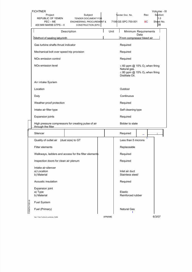
7/28/2019 Gas Turbine Data Sheet
http://slidepdf.com/reader/full/gas-turbine-data-sheet 38/59
FICHTNER Volume - III
Project Subject Tender Doc. No. Rev Section
REPUBLIC OF YEMEN TENDER DOCUMENT FOR 1.0
PEC – ME ENGINEERING, PROCUREMENT & 7195-GE-SPC-700-001 BC Sheet No.
400 MW MARIB GTPS – II CONSTRUCTION (EPC) 38
Sec-1 Gas Turbine & auxiliaries_ReBid APM/ME 6/3/07
F O R M T 9 - P R
E V - B
Minimum RequirementsDescription UnitData
Method of sealing labyrinth From compressor bleed air
Gas turbine shafts thrust indicator Required
Mechanical bolt over speed trip provision Required
NOx emission control Required
NOx emission level ≤ 60 ppm @ 15% O2 when firingNatural gas.
≤ 80 ppm @ 15% O2 when firingDistillate Oil.
Ai r intake System
Location Outdoor
Duty Continuous
Weather proof protection Required
Intake air filter type Self cleaning type
Expansion joints Required
High pressure compressors for creating pulse of air through the filter
Bidder to state
Silencer Required
Quality of outlet air (dust size) to GT Less than 5 microns
Filter elements Replaceable
Walkways, ladders and access for the filter elements Required
Inspection doors for clean air plenum Required
Intake air silencer
a) Location Inlet air duct
b) Material Stainless steel/
Acoustic insulation Required
Expansion joint
a) Type Elastic
b) Material Reinforced rubber
Fuel System
Fuel (Primary) Natural Gas

7/28/2019 Gas Turbine Data Sheet
http://slidepdf.com/reader/full/gas-turbine-data-sheet 39/59
FICHTNER Volume - III
Project Subject Tender Doc. No. Rev Section
REPUBLIC OF YEMEN TENDER DOCUMENT FOR 1.0
PEC – ME ENGINEERING, PROCUREMENT & 7195-GE-SPC-700-001 BC Sheet No.
400 MW MARIB GTPS – II CONSTRUCTION (EPC) 39
Sec-1 Gas Turbine & auxiliaries_ReBid APM/ME 6/3/07
F O R M T 9 - P R
E V - B
Minimum RequirementsDescription UnitData
Fuel (Standby) Distillate Oil
Fuel Analysis As given in General TechnicalSpecification
Liquid fuel atomisation Air atomisation (for continuousoperation)
Aux. compressor for start-up atomising air Required
Fuel pressure & flow regulator Required
Provision for Nitrogen purging after machine trip Required
Turbine Oil system
Type of oil Mineral/synthetic oil
Protection against fire hazard for oil piping around hightemperature piping and around oil tank
Required to be provided by thebidder
Main Lube oil pump
a) No. required One (1)
b) Type of pump Positive
displacement/Centrifugalc) Type of drive GT Shaft driven/A.C. motor
Auxiliary Lube oil pump
a) No. required One (1)
b) Type of pump Positive Displacement/Centrifugal
c) Type of drive AC motor driven
Hydraulic oil pump (if required)
a) No. required 2 x 100%
b) Type of pump Positive
displacement/centrifugalc) Type of drive A.C. motor driven
Jacking oil pump
a) Number required 1 (one)
b) Type of pump Positive displacement
c) Type of drive AC motor driven
Emergency oil pump
a) No. required One (1)
b) Type of pump Positive displacement type
c) Type of drive DC motor driven

7/28/2019 Gas Turbine Data Sheet
http://slidepdf.com/reader/full/gas-turbine-data-sheet 40/59
FICHTNER Volume - III
Project Subject Tender Doc. No. Rev Section
REPUBLIC OF YEMEN TENDER DOCUMENT FOR 1.0
PEC – ME ENGINEERING, PROCUREMENT & 7195-GE-SPC-700-001 BC Sheet No.
400 MW MARIB GTPS – II CONSTRUCTION (EPC) 40
Sec-1 Gas Turbine & auxiliaries_ReBid APM/ME 6/3/07
F O R M T 9 - P R
E V - B
Minimum RequirementsDescription UnitData
Oil cooler
a) No required Two (2) x 100%
b) Type Lube oil/water heat exchanger
c) Tube material Admiralty brass
Oil tank Electric heater to heat the oil in the tank duringcold season
Required
Lube Oil & Control Oil Filters To be provided with standby
element (Duplex type)
Vapour extractors
a) No. required Two (2)
b) Type of drive AC motor driven
c) Oil separators/mist
eliminators Required
Oil Purifier (Common for all 4 GTs))
Number No. One (1)
Type - Centrifuge
Capacity To Purify not less than 25% of the total oil quantity in the
lubricating systems of one unitper hour
Turning gear/ Ratchet Mechanism
a) Type of drive for turning gear AC motor or hydraulic turningdrive
b) Hand barring facility Required
Exhaust Gas Ducting
Duct material Carbon Steel
Insulation material (Internal) Ceramic Wool
Liner material (Internal) ASTM A 176 TYPE SS 409
Outside surface temp. to be maintained 60°C at maximum ambienttemp.
Exhaust Silencer Required
Exhaust Stack height (Minimum) Meters 30

7/28/2019 Gas Turbine Data Sheet
http://slidepdf.com/reader/full/gas-turbine-data-sheet 41/59
FICHTNER Volume - III
Project Subject Tender Doc. No. Rev Section
REPUBLIC OF YEMEN TENDER DOCUMENT FOR 1.0
PEC – ME ENGINEERING, PROCUREMENT & 7195-GE-SPC-700-001 BC Sheet No.
400 MW MARIB GTPS – II CONSTRUCTION (EPC) 41
Sec-1 Gas Turbine & auxiliaries_ReBid APM/ME 6/3/07
F O R M T 9 - P R
E V - B
1.7.0 GUARANTEES, REJECTION
Descript ion Unit Data
Particular Guarantees
Power generated as measured at generator terminals at 45°C, 60% RH and 1100 m above MSL
MW
NOx emission level (At 15% O2) for Natural gas ppmvd
NOx emission level (At 15% O2) for Natural gas ppmvd
Heat Rate at 45°C, 60% RH and 1100 m above MSL kJ/kWhr
General Guarantees
Sensitivity of electro-hydraulic speed governingsystem including governor valves
%
Maximum increase in running speed in case of sudden total or partial load reduction
%
Absence of excessive vibration during operation of the turbine generator. Maximum effective vibration
velocity measured at bearing housings.
mm/s
Guarantees for component life
Combustion Liner hrs
Transition piece hrs
Turbine Nozzles hrs
Turbine Buckets hrs
Noise level @ 1.0 m from equipment outline dbA

7/28/2019 Gas Turbine Data Sheet
http://slidepdf.com/reader/full/gas-turbine-data-sheet 42/59
FICHTNER Volume - III
Project Subject Tender Doc. No. Rev Section
REPUBLIC OF YEMEN TENDER DOCUMENT FOR 1.0
PEC – ME ENGINEERING, PROCUREMENT & 7195-GE-SPC-700-001 BC Sheet No.
400 MW MARIB GTPS – II CONSTRUCTION (EPC) 42
Sec-1 Gas Turbine & auxiliaries_ReBid APM/ME 6/3/07
F O R M T 9 - P R
E V - B
1.8.0 TECHNICAL DATA BY THE TENDERER
Descript ion Unit Data
General
Manufacturer
Model number
No. of units
Type
Performance parameters of GTG
at MCR for di fferent ambient siteconditions at 60% RH– withNatural gas Fuel
0°C 15°C 25.5°C 45°C
(Tenderer to provided similar datafor 75% MCR and 60% MCR after award of contract)
Output at generator terminal withpower factor of 0.8
MW
Total Auxiliary power consumptionfor GTG & auxiliaries
MW
Fuel (NG) consumption for fuel netcalorific value
Sm³/hr
Heat rate for net calorific value Kcal/KWhr
NOx level in exhaust gas ppm vd
Inlet air pressure drop mbar
Compressor outlet temp °C
Compressor mass flow Kg/s
Pressure ratio
Air fuel ratio
Combustion chamber pressure drop mbar
Turbine inlet temperature °C
Turbine exhaust gas pressure drop mbar
Turbine Exhaust gas pressure mbar
Turbine exhaust temp. °C

7/28/2019 Gas Turbine Data Sheet
http://slidepdf.com/reader/full/gas-turbine-data-sheet 43/59
FICHTNER Volume - III
Project Subject Tender Doc. No. Rev Section
REPUBLIC OF YEMEN TENDER DOCUMENT FOR 1.0
PEC – ME ENGINEERING, PROCUREMENT & 7195-GE-SPC-700-001 BC Sheet No.
400 MW MARIB GTPS – II CONSTRUCTION (EPC) 43
Sec-1 Gas Turbine & auxiliaries_ReBid APM/ME 6/3/07
F O R M T 9 - P R
E V - B
Descript ion Unit Data
Exhaust mass flow Kg/s
Exhaust gas enthalpy Kcal/kg
Performance parameters of GTGat MCR for different ambient siteconditions at 60% RH
0°C 15°C 25.5°C 45°C
- with Distillate Oil Fuel
(Tenderer to provided similar datafor 75% MCR and 60% MCR after award of contract)
Output at generator terminal with 0.8power factor
MW
Auxiliary power consumption for GTG & Auxiliaries
MW
Distillate oil consumption for fuel netcalorific value
Sm3/hr
Heat rate for net calorific value Kcal/KWhr
NOx level in exhaust gas ppm vd
Inlet air pressure drop mbar
Compressor outlet temp. °C
Compressor mass flow Kg/s
Pressure ratio
Air fuel ratio
Combustion chamber pressure drop mbar
Turbine inlet temp. °C
Turbine Exhaust gas pressure drop mbar
Turbine exhaust gas pressure mbar
Turbine exhaust temp. °C
Exhaust mass flow Kg/s
Exhaust gas enthalpy Kcal/kg
Operation data
Hours of operation before inspectionof Hot gas path
hrs

7/28/2019 Gas Turbine Data Sheet
http://slidepdf.com/reader/full/gas-turbine-data-sheet 44/59
FICHTNER Volume - III
Project Subject Tender Doc. No. Rev Section
REPUBLIC OF YEMEN TENDER DOCUMENT FOR 1.0
PEC – ME ENGINEERING, PROCUREMENT & 7195-GE-SPC-700-001 BC Sheet No.
400 MW MARIB GTPS – II CONSTRUCTION (EPC) 44
Sec-1 Gas Turbine & auxiliaries_ReBid APM/ME 6/3/07
F O R M T 9 - P R
E V - B
Descript ion Unit Data
Time from startup to 100% base
load (stage wise curves to befurnished)
Minimum load for continuousoperation of GTG
Normal base Min.
Hot start Min.
Expected Frequency of major overhauls during base load
After ........fired Hrs
Annual outage hours
Annual available hours of continuous operation at base load
hrs
No. of starts permissible for annualoperating hours above
hrs
Effect of additional starts onequipment life, beyond permissiblenumber
hrs
Hours of operation before first major overhaul
hrs
Feed back on operation of similar sets suppli ed elsewhere
- Year of commissioning
- Capacity and model
- Total operating hours logged withNatural gas
hours
- First major overhaul carried outafter
hours
- First hot gas path inspectioncarried out after
hours
- Healthiness of hot gas path after first inspection
- No. of unscheduled outage
- Reason for unscheduled outages
- History of spurious trips & shut-downs

7/28/2019 Gas Turbine Data Sheet
http://slidepdf.com/reader/full/gas-turbine-data-sheet 45/59
FICHTNER Volume - III
Project Subject Tender Doc. No. Rev Section
REPUBLIC OF YEMEN TENDER DOCUMENT FOR 1.0
PEC – ME ENGINEERING, PROCUREMENT & 7195-GE-SPC-700-001 BC Sheet No.
400 MW MARIB GTPS – II CONSTRUCTION (EPC) 45
Sec-1 Gas Turbine & auxiliaries_ReBid APM/ME 6/3/07
F O R M T 9 - P R
E V - B
Descript ion Unit Data
- Average annual operating hours
logged
Performance Correction Curves(All correction curves to befurnished)
Barometric pressure correctioncurve no.
For outputFor heat rate
Ambient temperature correction
curve no.
For outputFor heat rate
Fuel calorific value correction curveno.
For outputFor heat rate
Inlet air pressure drop correctioncurve no.
For outputFor heat rate
Exhaust gas pressure dropcorrection curve no.
For outputFor heat rate
Relative humidity correction curveno.
For outputFor heat rate
Speed correction curve no.
For outputFor heat rate
Ageing factor correction curve no.
For outputFor heat rate
Direction of rotation looking fromcompressor end

7/28/2019 Gas Turbine Data Sheet
http://slidepdf.com/reader/full/gas-turbine-data-sheet 46/59

7/28/2019 Gas Turbine Data Sheet
http://slidepdf.com/reader/full/gas-turbine-data-sheet 47/59
FICHTNER Volume - III
Project Subject Tender Doc. No. Rev Section
REPUBLIC OF YEMEN TENDER DOCUMENT FOR 1.0
PEC – ME ENGINEERING, PROCUREMENT & 7195-GE-SPC-700-001 BC Sheet No.
400 MW MARIB GTPS – II CONSTRUCTION (EPC) 47
Sec-1 Gas Turbine & auxiliaries_ReBid APM/ME 6/3/07
F O R M T 9 - P R
E V - B
Descript ion Unit Data
30°C CST50°C CST
Water content % wtSediment/ Particulate matter %wtSulphur %wt Ash content %wtCalcium ppmLead ppmSodium ppmPotassium ppmVanadium ppmNitrogen %wtNickel ppm Arsenic ppmChlorides ppm
Barium, manganese & phosphorous ppmFilterable dirt mg/100
mlCarbon residue %wtC/H2 ratioFlash point °CFire point °CType of additiveType of inhibitor
Layout Data
Total size of gas turbine generator unit (l x w x h)
MxMxM
Weight of gas turbine generator a Gas turbine kgb Electrical generator kgc Gas turbine generator complete
unitkg
Weight of heaviest single piece of equipment during erection
kg
Space requirement for pulling the
generator rotor beyond the gasturbine generator block
mm
Capacity of overhead crane for erection
Ton
Capacity of overhead crane/liftingtackle
a) For gas turbine maintenance Tonb) For pulling the generator rotor Ton
Moment of inertia of all rotating
masses connected to the generator shaft

7/28/2019 Gas Turbine Data Sheet
http://slidepdf.com/reader/full/gas-turbine-data-sheet 48/59
FICHTNER Volume - III
Project Subject Tender Doc. No. Rev Section
REPUBLIC OF YEMEN TENDER DOCUMENT FOR 1.0
PEC – ME ENGINEERING, PROCUREMENT & 7195-GE-SPC-700-001 BC Sheet No.
400 MW MARIB GTPS – II CONSTRUCTION (EPC) 48
Sec-1 Gas Turbine & auxiliaries_ReBid APM/ME 6/3/07
F O R M T 9 - P R
E V - B
Descript ion Unit Data
*
a) Generator
b) Reduction gear c) Turbine-compressor rotor d) Auxiliary gear boxe) Inertia constant
Gas turbine Air compressor
Type of compressor *
No. of compressor stages
No. of compressor casings
Outlet air pressure and temperature bar/°C
No. of bleeding points for supplyingcooling and sealing air and their locations
Compressor speed rpm
Quantity of air bled at points kg/s
Pressure of air bled at points bar
Air flow for turbine blade cooling Kg/s
Type of air flow regulation at partload
*
Maximum expected air leakage fromcasing parting planes and tap-off locations
Kg/s
Permissible leakage rate % *
Method of surge control *
Type of fixing of blades to rotor disc *
Type of fixing of rotor disc to rotor
No. and type of bearings
Lube oil flow to each bearing LPM
Compressor washing/cleaning
Method
Washing agent
Quantity of washing agent requiredper washing
m³

7/28/2019 Gas Turbine Data Sheet
http://slidepdf.com/reader/full/gas-turbine-data-sheet 49/59
FICHTNER Volume - III
Project Subject Tender Doc. No. Rev Section
REPUBLIC OF YEMEN TENDER DOCUMENT FOR 1.0
PEC – ME ENGINEERING, PROCUREMENT & 7195-GE-SPC-700-001 BC Sheet No.
400 MW MARIB GTPS – II CONSTRUCTION (EPC) 49
Sec-1 Gas Turbine & auxiliaries_ReBid APM/ME 6/3/07
F O R M T 9 - P R
E V - B
Descript ion Unit Data
Capacity of storage tank m³
Recommended frequency of compressor washing
Firedhours
Recommended level of fall inelectrical output for washing
MW
Materials of construction (fullspecification as per ASTM/BS/DINor any other standard shall bementioned)
Casing
Rotor discs
Rotating blades *
Stationary blades
Shaft
Rotating blades shroud/lacing wire
Casing bolts & nuts
Bearing
Protective coating material
Expected life of hrs
- blades hrs- bearings
Normal rated power input tocompressor
KW
Combustion System NaturalGas Distillate oil
Type
No. of combustion chambers
No. of burners
NaturalGas
Distillate oil
Design heat loading per combustionchamber
Kcal/hr
Fuel pressure at burner bar

7/28/2019 Gas Turbine Data Sheet
http://slidepdf.com/reader/full/gas-turbine-data-sheet 50/59
FICHTNER Volume - III
Project Subject Tender Doc. No. Rev Section
REPUBLIC OF YEMEN TENDER DOCUMENT FOR 1.0
PEC – ME ENGINEERING, PROCUREMENT & 7195-GE-SPC-700-001 BC Sheet No.
400 MW MARIB GTPS – II CONSTRUCTION (EPC) 50
Sec-1 Gas Turbine & auxiliaries_ReBid APM/ME 6/3/07
F O R M T 9 - P R
E V - B
Descript ion Unit Data
Efficiency of combustor at designpoint
Pressure drop across combustor at100% fuel firing rate at site output
bar
Materials of construction
Combustion chamber Combustion wrapper Flame tubesFuel pipingCombustion chamber lining andcoating materialFuel burner
Transition piece
Gas Turbine
No. of stages
Type of casing
Method of supporting casing
Type of fixing for combustor burner
Type of fixing of blades to rotor disc
Type of fixing rotor disc to rotor
No. and type of air seals used
No. of air ports
No. of intrascope points/viewingpoints and their position
Materials of construction (fullspecification as per ASTM/DIN/BSor any other standard shall bementioned)
Turbine stationary blading (for various stages)
Turbine rotor blades (for variousstages)
Turbine rotor disc
Turbine shaft
Turbine casing
Turbine casing bolts & nuts

7/28/2019 Gas Turbine Data Sheet
http://slidepdf.com/reader/full/gas-turbine-data-sheet 51/59
FICHTNER Volume - III
Project Subject Tender Doc. No. Rev Section
REPUBLIC OF YEMEN TENDER DOCUMENT FOR 1.0
PEC – ME ENGINEERING, PROCUREMENT & 7195-GE-SPC-700-001 BC Sheet No.
400 MW MARIB GTPS – II CONSTRUCTION (EPC) 51
Sec-1 Gas Turbine & auxiliaries_ReBid APM/ME 6/3/07
F O R M T 9 - P R
E V - B
Descript ion Unit Data
Turbine blades protective coating
(for various stages)
*
Expected life of turbine blades andnozzles
Bearings
No. and type of bearings in gasturbine
Optimum operating temp °C
Max. operating temp. °C
Lining material
Min. pressure at which lube oil isrequired
bar
Quantity of lube oil per bearing lpm
Axial thrust bearing
Number *
Type
Optimum operating temp °C
Max. operating temp. °C
Lining material
Min. pressure at which lube oil isrequired
bar
Quantity of lube oil required per bearing
lpm
Details of turbine blade washing (if applicable)
Washing agent
Frequency of washing After ...firedhours
Recommended level of fall inelectrical output for washing
KW
No of blades with protective coating
Type of coating

7/28/2019 Gas Turbine Data Sheet
http://slidepdf.com/reader/full/gas-turbine-data-sheet 52/59
FICHTNER Volume - III
Project Subject Tender Doc. No. Rev Section
REPUBLIC OF YEMEN TENDER DOCUMENT FOR 1.0
PEC – ME ENGINEERING, PROCUREMENT & 7195-GE-SPC-700-001 BC Sheet No.
400 MW MARIB GTPS – II CONSTRUCTION (EPC) 52
Sec-1 Gas Turbine & auxiliaries_ReBid APM/ME 6/3/07
F O R M T 9 - P R
E V - B
Descript ion Unit Data
Intake Air System
Intake air filter
Manufacturer
Type of filter
Design air flow Kg/s
No. of filter elements Nos.
No. of modules Nos.
No.of filter elements/module Nos.
No. of Tiers Nos.
Air flow per filter element kg/s
Air velocity - design m/s
Particle size at filter outlet microns
Media material
Expected life of filter material hrs
Method of cleaning the filters
Temperature/ pressure of purgingair
°C/bar
Flow of air Kg/s *
Intake air silencer **
Location *
Type
Sound absorbent
Baffle material
No. of silencers Nos.
Inlet air ducting
Material of construction
Size m x m x m
Flow velocity in duct m/s

7/28/2019 Gas Turbine Data Sheet
http://slidepdf.com/reader/full/gas-turbine-data-sheet 53/59
FICHTNER Volume - III
Project Subject Tender Doc. No. Rev Section
REPUBLIC OF YEMEN TENDER DOCUMENT FOR 1.0
PEC – ME ENGINEERING, PROCUREMENT & 7195-GE-SPC-700-001 BC Sheet No.
400 MW MARIB GTPS – II CONSTRUCTION (EPC) 53
Sec-1 Gas Turbine & auxiliaries_ReBid APM/ME 6/3/07
F O R M T 9 - P R
E V - B
Descript ion Unit Data
Thickness of duct mm
Particulars of inside protection withsuitable coatings Whether ductingsare suitably designed to preventundue vibration?
Yes/No
Expansion joints- Type- Number Nos.- Material of construction
Necessary galvanised supportsprovided
Yes/No
Turning vanes at all bends provided Yes/No
Manholes/access doors for inspection provided
Yes/No
Governing system
Type of governingSteady state speed regulation %Temporary speed variation when fullload is thrown off
%
Permanent rate of speed variationwhen full load is thrown off
% *
Speed drop characteristics andrange of adjustment
Turbine Oil System
Number of circulations (per hour) No.
Lubrication oil system pressure bar
Lubrication oil system capacity m³
Lubrication oil system flow rate m³/hr
Temperature of oil at inlet to bearing °C
Temperature of oil at inlet to bearing °C
Hydraulic oil pressure bar
Oil reservoir
Total quantity of oil in the system m3
Capacity of the oil reservoir m3
Operating capacity of the oilreservoir between high and low
m3

7/28/2019 Gas Turbine Data Sheet
http://slidepdf.com/reader/full/gas-turbine-data-sheet 54/59
FICHTNER Volume - III
Project Subject Tender Doc. No. Rev Section
REPUBLIC OF YEMEN TENDER DOCUMENT FOR 1.0
PEC – ME ENGINEERING, PROCUREMENT & 7195-GE-SPC-700-001 BC Sheet No.
400 MW MARIB GTPS – II CONSTRUCTION (EPC) 54
Sec-1 Gas Turbine & auxiliaries_ReBid APM/ME 6/3/07
F O R M T 9 - P R
E V - B
Descript ion Unit Data
levels
Following instruments provided
- Level indicators- High and low level alarms- Temp. indicator
Oil reservoir tank material
Lube oil strainers- Type/make- Numbers Nos- Size of the mesh Microns * *- Material
- Max allowable pressure drop bar
Main lube oil pumps
Type/ makeNumber Capacity M
3/hr
Discharge pressure bar (g)Rotational speed rpmDrive motor rating type/make kwWhether flame proof construction
Material of construction- Impeller - Shaft- Casing
Auxiliary lube oil pumpType/ makeNumber Capacity M
3/hr
Suction pressure bar (g)Discharge pressure bar Rotational speed rpmDrive motor rating type/make KWWhether flame proof constructionMaterial of Construction
- Impeller - Shaft- Casing
Yes/NoHydraulic oil pumpsType/ makeNumber Capacity M
3/hr
Suction pressure bar (g)Discharge pressure bar (g)
Rotational speed rpmWhether flame proof constructionMaterial of construction

7/28/2019 Gas Turbine Data Sheet
http://slidepdf.com/reader/full/gas-turbine-data-sheet 55/59
FICHTNER Volume - III
Project Subject Tender Doc. No. Rev Section
REPUBLIC OF YEMEN TENDER DOCUMENT FOR 1.0
PEC – ME ENGINEERING, PROCUREMENT & 7195-GE-SPC-700-001 BC Sheet No.
400 MW MARIB GTPS – II CONSTRUCTION (EPC) 55
Sec-1 Gas Turbine & auxiliaries_ReBid APM/ME 6/3/07
F O R M T 9 - P R
E V - B
Descript ion Unit Data
- Impeller - Shaft
- Casing
Jacking oil pumpType/ makeNumber Capacity M
3/hr Yes/No
Suction pressure bar (g)Discharge pressure bar (g)Rotational speed rpmDrive motor rating type/make KWWhether flame proof construction
Material of construction
- Impeller - Shaft- Casing
Emergency lube oil pump (DC motor driven)Type/ makeNumber Capacity m
3/hr
Discharge pressure bar (g)Speed rpmContinuous motor ratingMotor type/make (Motor details to befurnished Motor data sheets)
Oil coolers
Type/ MakeNo. of coolersNo. operating during full loadoperationOil capacity of each cooler m
3/hr
Oil side pressure drop bar Oil temperature
- Inlet / outlet °C/°CWater flow through each cooler m
3/hr
Water temperature- Inlet / outlet °C/°C
Water side pressure drop bar Water side drop at 10% tubes inplugged conditionCooling surface area m²
Materials of construction- Shell- Tube *- Tube sheet
Location of the oil cooler assembly
Tube removal space required Drainand vent connection with pad locked
m

7/28/2019 Gas Turbine Data Sheet
http://slidepdf.com/reader/full/gas-turbine-data-sheet 56/59
FICHTNER Volume - III
Project Subject Tender Doc. No. Rev Section
REPUBLIC OF YEMEN TENDER DOCUMENT FOR 1.0
PEC – ME ENGINEERING, PROCUREMENT & 7195-GE-SPC-700-001 BC Sheet No.
400 MW MARIB GTPS – II CONSTRUCTION (EPC) 56
Sec-1 Gas Turbine & auxiliaries_ReBid APM/ME 6/3/07
F O R M T 9 - P R
E V - B
Descript ion Unit Data
valves provided
Weight of cooler i. Dry weight Kgii. Wet weight Kg
Oil filters Lube oil Hydraulicfilter oil filter
TypeMakeNos offeredFiltration size micronsDesign flow rates m
3/hr
Pressure drop bar
Oil Purifier (Portable) Lube oil Hydraulicfilter oil filter
Manufacturer -Number No.Type -Capacity %Heater rating kWRating of drive kW
Turning Gear or Barring system
Type/MakeBarring speed rpm
Power required (if motor driven)
Starting Device
Type/MakeOutput rating KW
Detailed write-up on the startingdevice shall be furnished
Reduction Gear box (BetweenGas Turbine and Generator)
Make/ Type/Design code
Input shaft speed rpm
Output shaft speed rpm
Efficiency %
Lubricating oil requirement l/s
Maximum permissible shock loadingService factor
Designed power transmissioncapacity
MW

7/28/2019 Gas Turbine Data Sheet
http://slidepdf.com/reader/full/gas-turbine-data-sheet 57/59
FICHTNER Volume - III
Project Subject Tender Doc. No. Rev Section
REPUBLIC OF YEMEN TENDER DOCUMENT FOR 1.0
PEC – ME ENGINEERING, PROCUREMENT & 7195-GE-SPC-700-001 BC Sheet No.
400 MW MARIB GTPS – II CONSTRUCTION (EPC) 57
Sec-1 Gas Turbine & auxiliaries_ReBid APM/ME 6/3/07
F O R M T 9 - P R
E V - B
Descript ion Unit Data
Weight Kg
Material of construction
ShaftsPinionGearsCasingCouplings Between Gas
Turbine & Accessory Gear
box
- Lubricating oil quantity (if required)
lpm
- Material of construction- Rating MW- Service factor - Efficiency %- Weight kg *- Design code
GT Exhaust Ducting Welded / Bolted
Type
Design & fabrication code
Gas flowOperating (at 0°C/15°C/30°C) kg/sec.
Design kg/sec
Design pressure mbar
Max. allowable back pressure mmwc
Gas temperature
Operating (at 0°C/15°C/30°C) °C
Design °C
Gas path dimension
Gas path area m²
Gas velocity m/sec
Pressure drop (at 0°C/15°C/30°C) mmwc
Pressure drop at design flow mmwc
Constructional details
External Duct plate
Manufacturer - sides / bottom / top
Material - sides / bottom / top mm
Thickness - sides / bottom / top mm
Corrosion allowance - sides / bottom/ top
mm
Coefficient of expansion mm/mm °C
Design metal temperature °C
Internal liner
Manufacturer Material - sides / bottom / top mm

7/28/2019 Gas Turbine Data Sheet
http://slidepdf.com/reader/full/gas-turbine-data-sheet 58/59
FICHTNER Volume - III
Project Subject Tender Doc. No. Rev Section
REPUBLIC OF YEMEN TENDER DOCUMENT FOR 1.0
PEC – ME ENGINEERING, PROCUREMENT & 7195-GE-SPC-700-001 BC Sheet No.
400 MW MARIB GTPS – II CONSTRUCTION (EPC) 58
Sec-1 Gas Turbine & auxiliaries_ReBid APM/ME 6/3/07
F O R M T 9 - P R
E V - B
Descript ion Unit Data
Thickness - sides / bottom / top mm
Corrosion allowance - sides / bottom
/ top
mm
Coefficient of expansion mm/mm °C
Design metal temperature °C
Duct reinforcement members/stiffenersManufacturer
Material - sides / bottom / top
Size
Flanges
Manufacturer
Location
Dimension (LxWxThick) mm
Material
Insulation
Manufacturer
Material
No of layers
Thickness per layer mm
Insulation density kg/m3
Surface temperature of duct atdesign flow
°C
Loads (kg)
Static
DynamicThermal movement in all directions mm
Forces and moments
Turning vanes at all bends provided Yes/No
Support type?
Whether ductings are suitablydesigned to prevent vibration
Gas Turbine Exhaust Stack
Flow medium
Gas flow quantity kg/sec
Stack DimensionTop of stack elevation m
Stack dia mm
Exhaust gas velocity m/sec
External shell platethickness
mm
Air gap mm
corrosion allowances
Side mm
Bottom mm
Top mm
External shell material
Internal shell material
Insulation thickness material

7/28/2019 Gas Turbine Data Sheet
http://slidepdf.com/reader/full/gas-turbine-data-sheet 59/59
FICHTNER Volume - III
Project Subject Tender Doc. No. Rev Section
REPUBLIC OF YEMEN TENDER DOCUMENT FOR 1.0
PEC – ME ENGINEERING, PROCUREMENT & 7195-GE-SPC-700-001 BC Sheet No.
400 MW MARIB GTPS – II CONSTRUCTION (EPC) 59
Descript ion Unit Data
Liner material
Outside surface temperature of
ducting to be maintained
°C
Design pressure mmWC
Design gas velocity m/sec
Design metal temperature °C
Gas Turbine Exhaust Silencer
Flow medium
Noise data considered
External shell material
Absorption Insulation material
Liner materialOutside surface temperature of ducting to be maintained
°C
Design pressure mmWC
Non metallic Expansion Jo ints
Flow medium
No. of Expansion joints consideredand its locationDesign pressure mmWC
Thermal movements Axial mm
Lateral mm
Vertical mm
Loads
Static N
Dynamic N
Flange dimension
Insulation material & density
Cladding material
Note : * In the data sheets indicate that the data may be furn ished after award of contract . Al l other data to be fi lled in by the Tenderer dur ing Bid stage itself .