gas service pipe and in-house installation technologies in
TRANSCRIPT

Session 1
Gas service pipe and in-house installation technologies in Germanytechnologies in Germany
Werner Wessing
1

Gas service pipe and in‐house i ll i h l i i Ginstallation technologies in Germany
Basis: DVGW‐TRGI G 600
2
Gas installations in Germany
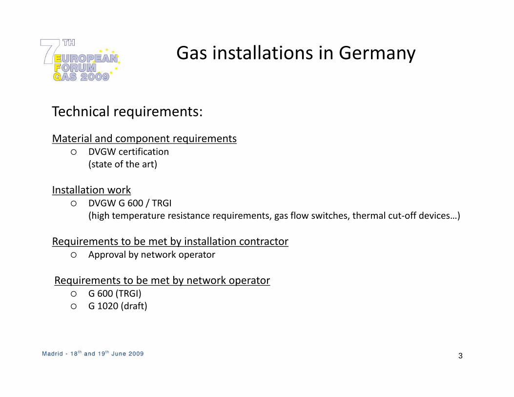
Technical requirements:
Material and component requirementsDVGW certification(state of the art)
Installation workDVGW G 600 / TRGI(high temperature resistance requirements, gas flow switches, thermal cut‐off devices…)
Requirements to be met by installation contractorApproval by network operator
Requirements to be met by network operatorG 600 (TRGI)G 1020 (draft)
3
Operation & maintenance, i t ll ti t tgas installation, system operators
A gas installation designed and built to comply with statutory as well as g g p y yDVGW‐TRGI requirements provides the basis for proper, long‐lasting operation.
According to Section 13 of the German Low Pressure Connection Ordinance (NDAV), the operator (legal person for whom the connection is made) is responsible for the proper condition of the gas system downstream of the
i i l i l i h h i f l dmain isolation valve with the exception of gas pressure regulators and metering devices that do not belong to him (general duty of occupier to make land and/or premises safe for persons or vehicles).
The operating and maintenance instructions in DVGW‐TRGI provide the operator with the necessary information on how to comply with this duty.
4
Source: DVGW-TRGI G 600
Installation example of single‐family h ith b thome with a basement
Thermische Absperr-einrichtung (TAE)
Gaskessel mit Warmwasser-Speicherim Keller.Absicherung der Gasleitung durchGasströmungswächter anAnbohr-T-Stück / Gasdruckregleri H
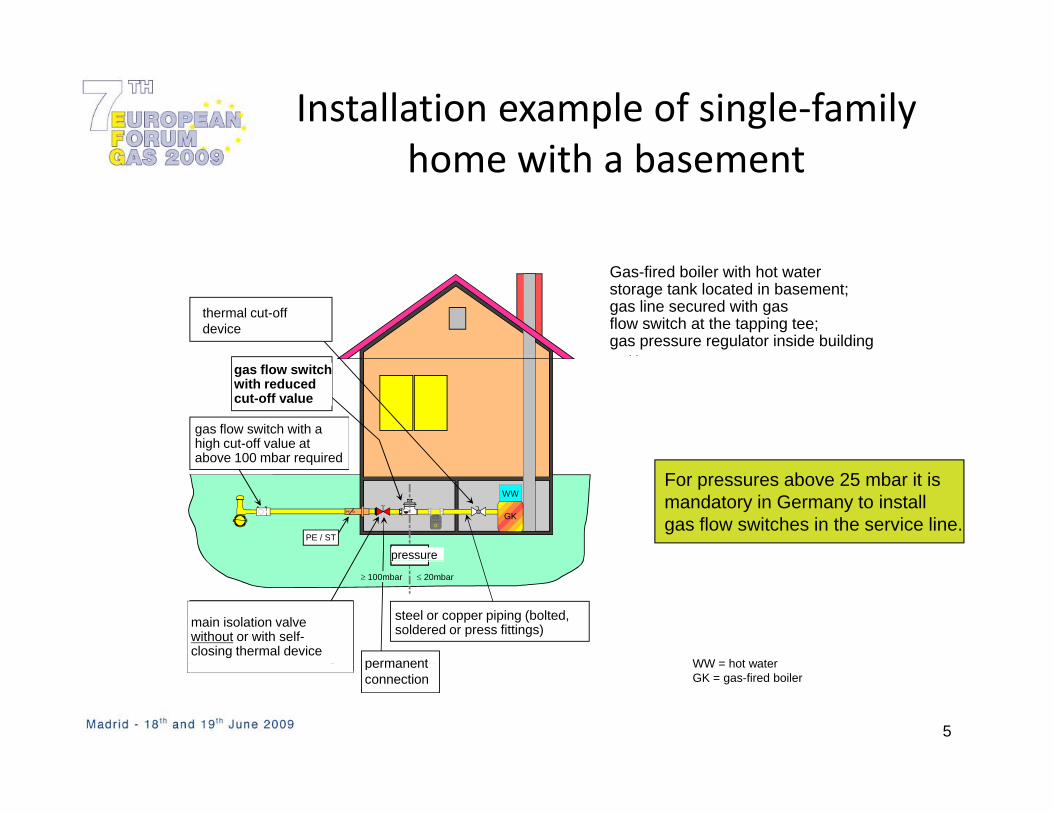
Gas-fired boiler with hot waterstorage tank located in basement;gas line secured with gasflow switch at the tapping tee;gas pressure regulator inside building
thermal cut-off device
Gasdruckreglermit reduziertemSchließwert
Gasströmungswächtermit großem Schließwertbei >100 mbar erforderlich
im Haus. gas flow switch with reduced cut-off value
gas flow switch with ahigh cut-off value atabove 100 mbar required
PE / ST
PE St
G
WW
GK
Druck
bei >100 mbar erforderlich
For pressures above 25 mbar it ismandatory in Germany to installgas flow switches in the service line.
above 100 mbar required
pressure
Nichtlösbare
≤ 20mbar≥ 100mbar
Stahl- oder Kupferrohrinstallation(geschraubt, verpresst, verlötet)
Hauptabsperreinrichtungohne bzw. mitselbstschließender,thermischer Vorrichtung
main isolation valvewithout or with self-closing thermal device
permanent
steel or copper piping (bolted, soldered or press fittings)
p
WW = hot water
5
2002NichtlösbareVerbindung
g permanent connection
WW = hot waterGK = gas-fired boiler
Components to increase safety in gas di t ib ti t / i t ll tidistribution systems / installations
G t öBauteile Thermische Absperr-einrichtung (TAE)
Gasströmungs-wächter (GS)
Druckregler mit integriertem Gasströmungswächter (GDR)
S ti l
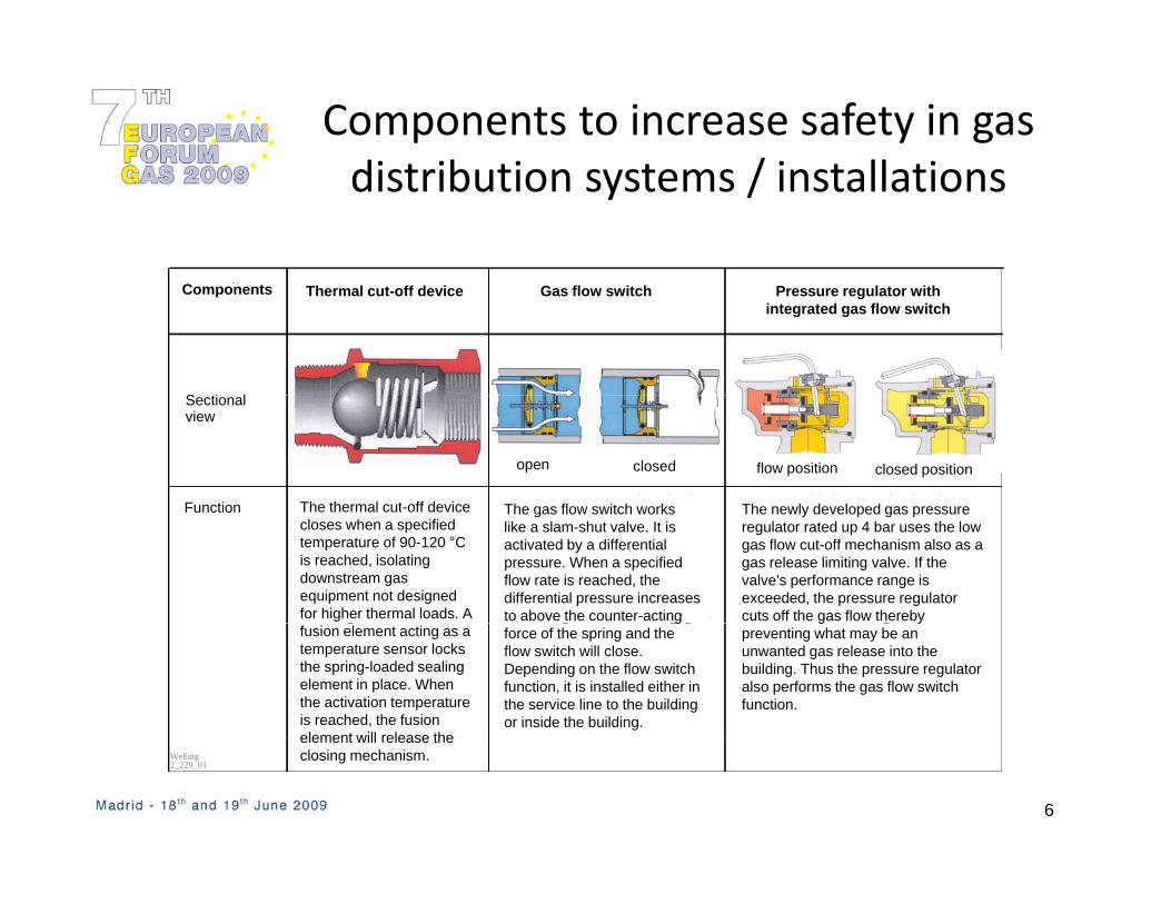
Components Thermal cut-off device Gas flow switch Pressure regulator with integrated gas flow switch
Schnittbild
Funktion Die thermische Absperrein- Der Gasströmungswächter (GS) Im neu entwickelten Gasdruckregler GDR
offen geschlossen Arbeitsposition Schließposition
The thermal cut-off deviceFunction
Sectional view
open closed flow position closed position
The gas flow switch works The newly developed gas pressurerichtung schließt beim Erreichen einer Auslöse-temperatur (90°C-120°C) und verhindert den Gasfluss zu den nachgeschalteten, nicht höher thermisch belastbaren Gasanlagen. Ein Schmelzein-
funktioniert wie ein Schnell-schlussventil, dessen Auslösung auf der Bildung eines Differenz-druckes basiert. Beim Erreichen eines definierten Grenzwertes für den Durchfluss wird die Differenz-druckkraft größer als die entgegen-
bis max. 4 bar wird der für die Funktion der Gasmangelsicherung eingebaute Mechanismus (Schließen bei Wegfall des Vordrucks) auch als Ausströmbegren-zungsventil eingesetzt. Bei Überschreiten des Leistungsbereiches schließt der GDR und verhindert damit möglicherweise
The thermal cut off device closes when a specified temperature of 90-120 °C is reached, isolating downstream gas equipment not designed for higher thermal loads. A
Function The gas flow switch works like a slam-shut valve. It is activated by a differential pressure. When a specified flow rate is reached, the differential pressure increases to above the counter-acting
The newly developed gas pressure regulator rated up 4 bar uses the low gas flow cut-off mechanism also as a gas release limiting valve. If the valve's performance range is exceeded, the pressure regulator cuts off the gas flow thereby g
satz, der als Temperatur-sensor fungiert, arretiert bei der TAE mit einer Druckfeder den vorgespannten Schließ-körper. Wird die Auslöse-temperatur erreicht, gibt der Schmelzkörper den Schließ-
g g gwirkende Federkraft. Das GS schließt. Je nach Aufgabe des GS liegt der Einbauort in der Hausan-schlussleitung oder in der Gas-Inneninstallation.
geinen unkontrollierten Gasaustritt ins Gebäude. Die GS-Funktion wird hiermit vom Druckregler übernommen.
fusion element acting as a temperature sensor locks the spring-loaded sealing element in place. When the activation temperature is reached, the fusion element will release the
gforce of the spring and the flow switch will close. Depending on the flow switch function, it is installed either in the service line to the building or inside the building.
g ypreventing what may be an unwanted gas release into the building. Thus the pressure regulator also performs the gas flow switch function.
6
2002Weßing2_229_01
Schmelzkörper den Schließkörper frei.element will release the closing mechanism.

Piping system
M l i f il h i ll i i i liMulti‐family home, gas meter in cellar, connection via service line serving additional apartments in back building
cellar installation
7
Z = meter
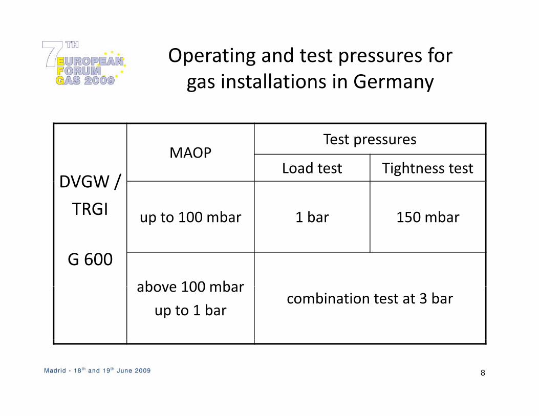
Operating and test pressures for i t ll ti i Ggas installations in Germany
DVGW /
MAOPTest pressures
Load test Tightness testDVGW /
TRGI up to 100 mbar 1 bar 150 mbar
G 600above 100 mbarabove 100 mbar
up to 1 barcombination test at 3 bar
8

Operator responsibilities (1)
All in‐house piping downstream of the main isolation valve is the responsibility of the operator.responsibility of the operator.
I h i i t b t t d i t d d t h i l
DVGW-TRGI G 600 requirements:
‐ In‐house piping must be protected against damage due to mechanical, chemical and thermal stresses.
Proper stable piping support must be ensured at all times‐ Proper, stable piping support must be ensured at all times.
‐ If in‐house lines are subsequently enclosed to be hidden from view, appropriate venting of the resulting voids / enclosures must be ensured.appropriate venting of the resulting voids / enclosures must be ensured.
‐ Remaining line openings (pipe ends and outlets) must be properly closed off; a closed isolation valve alone does not suffice.
9

Operator responsibilities (2)
If rooms are used for purposes other than those for which they were‐ If rooms are used for purposes other than those for which they were originally designated, an authorised installation company or the grid operator will have to examine any impact on existing lines.
‐ The exact location of lines hidden from view must be known.
‐ Gas hose lines must be used such that there is no tension on, or kinking or, gtwisting of, the line. Like the valve on the appliance the gas hose lines must not be subjected to excessive temperatures.
‐ Isolation devices must be fully operational and accessible at all times.

Operator responsibilities (3)
Inspections and inspection intervalsInspections and inspection intervals
‐ The operator must visually inspect the piping or have the piping visually‐ The operator must visually inspect the piping or have the piping visuallyinspected once every year, making sure there is no smell of gas.
‐ The operator must have the operability and tightness checked by anp p y g yauthorised installation company every 12 years.
11

Tampering made difficultExample: Gas flow switch installed in the piping
Single and double family homes
No passive measures required because room is not generally accessible
K or M type:Closing factor: f < 1.8
12
Source: DVGW-TRGI G 600Closing factor: f 1.8

Tampering made difficult
Multi‐family home with central gas use
Example: Gas flow switch installed in the piping
Multi family home with central gas use
a) no “generally accessible room”or
b) permanent connection(s)b) permanent connection(s)or
c) secured non‐permanent connection(s)
Multi‐family home with gas appliances installed in the individual apartments a) no “generally accessible room”
ororb) permanent connection(s)
orc) secured non‐permanent connection(s)
K or M type:
13
Source: DVGW-TRGI G 600K or M type:Closing factor: f < 1.8
Z = meter

Gas line routing
Routing of in‐house plastic gas lines if connected to a single gas appliance
gas appliance
Routing of in‐house plastic gas lines if connected to a distribution manifold
gas appliance
K type:
14
K type:Closing factor: f <1.45 Source: DVGW-TRGI G 600Z = meter
In‐house gas installations in Germany
Conclusion:
The low accident rate caused by in‐house gas installations show the high quality standards in Germany.
There is a comprehensive set of technical codes issued by DVGW covering all areas from design and construction to g goperation.
Only certified companies are allowed to perform gas installationOnly certified companies are allowed to perform gas installation work in Germany.
Proven compliance with high safety standards
15
Proven compliance with high safety standards