gas-fired indoor and outdoor duct furnaces
TRANSCRIPT

5-173.7 • JUNE, 2013
GAS-FIRED INDOOR AND OUTDOORDUCT FURNACES
INDOOR GRAVITY AND POWER VENTED DFG/DFP, DBG/DBP, DCG/DCP
INDOOR SEPARATED COMBUSTION DFS, DBS, DCS
OUTDOOR GRAVITY AND POWER EXHAUSTED “H” SERIES

5-173.7
TABLE OF CONTENTS
A complete line of both indoor and outdoor heating and ventilating equipment is offered. This catalog describes in detail the gas-fired, gravity vented, power vented, and separated combustion duct furnace/make-up air units.
Depending on the requirements of the application, the duct furnace can be ordered either by itself, a furnace with a blower section, a furnace with a blower and cooling coil sections, a
furnace with a blower and downturn sections, or a furnace with a blower, cooling coil, and downturn sections. With these configurations, the units can satisfy a building’s heating, make-up air, cooling, or ventilating requirements.
This catalog describes the design benefits, construction features, performance data, unit selection procedure, control applications, and the optional and accessory devices available.
Table of Contents PageFeatures and Benefits .......................................................................................................................................................3Duct Furnace Design Features ......................................................................................................................................4-5Duct Furnace Performance Data .......................................................................................................................................6Duct Furnace Pressure Drop Curves ................................................................................................................................7Duct Furnace Unit Selection .............................................................................................................................................8Duct Furnace Unit Dimensions ....................................................................................................................................9-13System Unit Design Features .....................................................................................................................................14-15System Unit General Performance Data ....................................................................................................................16-17Model Nomenclature Description ...............................................................................................................................18-22Options .......................................................................................................................................................................24-26Thermostats ....................................................................................................................................................................27Accessories ....................................................................................................................................................................28Control Applications ...................................................................................................................................................29-33System Unit Selection ................................................................................................................................................34-35Option & Accessory Pressure Drop Data ........................................................................................................................36Blower Performance Data ..........................................................................................................................................37-39Sheave Arrangements .....................................................................................................................................................40Electrical Data .................................................................................................................................................................41Motor Data ..................................................................................................................................................................42-44System Unit Dimensions - Indoor Gravity Vented / Power Vented / Separated Combustion .....................................46-51System Unit Dimensions - Outdoor Gravity Vented / Power Vented ..........................................................................52-55Dimensions - Indoor Unit Base .......................................................................................................................................56Dimensions - Outdoor Unit Base ...................................................................................................................................57Dimensions - Roof Curbs (Outdoor) ................................................................................................................................58Dimensions - Rainhood and Birdscreen (Outdoor) .........................................................................................................59Dimensions - Remote Panel ............................................................................................................................................59System Unit Weights .......................................................................................................................................................60Cooling Cabinet Specifications ...................................................................................................................................62-63DX Cooling Coil Performance Data ............................................................................................................................64-65Chilled Water Cooling Coil Performance Data ...........................................................................................................66-67Cooling Coil Dimensions .................................................................................................................................................68Evaporative Cooler Specifications and Dimensions (Outdoor) .................................................................................69-70Specifications .............................................................................................................................................................71-74Model Nomenclature .......................................................................................................................................................75
WARNINGDo not locate ANY gas-fired unit in areas where chlorinated, halogenated or acid vapors are present in the atmosphere.
WARNINGAppliances must not be installed where they may be exposed to a potentially explosive or flammable atmosphere.
Refer to the Page 75 (inside back cover) for Model Nomenclature
As Modine Manufacturing Company has a continuous product improvement program, it reserves the right to change design and specifications without notice.
2
!!
5-173.7
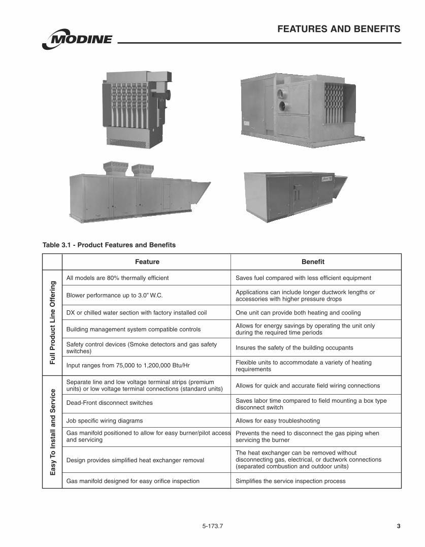
Job specific wiring diagrams
Allows for quick and accurate field wiring connections
Input ranges from 75,000 to 1,200,000 Btu/Hr
All models are 80% thermally efficient
Blower performance up to 3.0” W.C.
Building management system compatible controls
Saves fuel compared with less efficient equipment
Applications can include longer ductwork lengths or accessories with higher pressure drops
One unit can provide both heating and cooling
Allows for energy savings by operating the unit only during the required time periods
Insures the safety of the building occupants
Flexible units to accommodate a variety of heating requirements
Safety control devices (Smoke detectors and gas safety switches)
Dead-Front disconnect switches
DX or chilled water section with factory installed coil
Design provides simplified heat exchanger removalThe heat exchanger can be removed without disconnecting gas, electrical, or ductwork connections (separated combustion and outdoor units)
Simplifies the service inspection processGas manifold designed for easy orifice inspection
Feature
Fu
ll P
rod
uct
Lin
e O
ffer
ing
Eas
y To
Inst
all a
nd
Ser
vice
Benefit
3
FEATURES AND BENEFITS
Table 3.1 - Product Features and Benefits
Gas manifold positioned to allow for easy burner/pilot access and servicing
Saves labor time compared to field mounting a box type disconnect switch
Allows for easy troubleshooting
Prevents the need to disconnect the gas piping when servicing the burner
Separate line and low voltage terminal strips (premium units) or low voltage terminal connections (standard units)

Indoor Gravity Vented (DFG)The indoor gravity vented duct furnace was designed to be an economical choice for use with a building’s heating, heating/cooling and make-up air systems. Available in 11 gravity vented model sizes, the unit covers a wide variety of applications. They have input ranges from 75,000 to 400,000 Btu/Hr and can operate on either natural or propane gas. The airflow direction can be spec ified when ordering the unit. The duct furnace is certified for location either upstream or downstream from cooling coils and has a drain pan that allows connection to a condensate drain line. Because the unit relies on a natural draft to vent properly, power vented units should be considered if the vent system is horizontal or if the space in which the unit is located is generally under a negative pressure.
Indoor Power Vented (DFP)Model DFP includes all the items featured for Model DFG, but adds an integral power exhauster that allows for:
pipe possible.
buildings with inadequate make up air.
vent losses.
Indoor Separated Combustion (DFS)Model DFS builds upon the advantages of the Power Vented Model DFP, but is specifically designed for buildings with hostile environments, such as dirty or high humidity applications. This model features:
doors to seal components from the environment.
has plenty of fresh, clean air.
losses are essentially eliminated, further improving building efficiency.
4
DUCT FURNACE DESIGN FEATURES
5-173.6
Model DFS
Figure 4.1 - Indoor Duct Furnaces
Figure 4.2 - Indoor Duct Furnaces
Model DFG
Model HFG
Model DFP
Model HFP
Outdoor Gravity & Power Exhausted (HFG/HFP)The outdoor duct furnace was designed for use with a building’s heating, heating/cooling and make-up air systems. Available in 11 gravity vented or power exhausted model sizes, the unit covers a wide variety of applications. They have input ranges from 75,000 to 400,000 Btu/Hr and can operate on either natural or propane gas. The airflow direction can be specified when ordering the unit. The duct furnace is certified for location either upstream or downstream from cooling coils and has holes to drain any condensate that may form on the roof.
Figure 4.3 - Outdoor Duct Furnaces
Standard Features:
powder paint finish on exterior casing parts (HFG, HFP).
separator strip.
single-stage gas valve for operation on natural gas.
into the discharge) with slide-out burner drawer.
gasketed doors (DFS).

DUCT FURNACE DESIGN FEATURES
55-173.6
Optional Features - Factory Installed
Note: A 409 stainless steel heat exchanger and burner is recommended when installed downstream of a cooling coil or evaporative cooler, or when the combined entering/return air to the unit is below 40°F.
modulation using a 0-10VDC or 4-20mA signal.
4 duct furnaces with one discharge air sensor.
208/230/460/575V/3Ph.
HFP).
and low voltage terminal strips (DFG, DFP).
Accessories - Field Installed
Figure 5.1).
(DFP, DFS, HFP).
stage units.
override for the duct thermostat.
Figure 5.1 - Concentric Vent Kits (Model DFS)
Horizontal Concentric Vent Kit
INLET GUARDASSEMBLY
(BY MODINE)
CONCENTRICVENT ADAPTER
(BY MODINE)
DRIP LEG ANDCLEANOUT CAP
(FIELD SUPPLIED)
VENT CAP(BY MODINE)
VENT CAP(BY MODINE)
INLET TERMINAL(BY MODINE)
CONCENTRICVENT ADAPTER
(BY MODINE)
DRIP LEG ANDCLEANOUT CAP
(FIELD SUPPLIED)
Vertical Concentric Vent Kit
Variable Air Movement Applications When the air mover supplied by others can provide variable air movement (i.e. 2-speed or variable frequency drive units), the certified allowable minimum CFM of the outdoor duct furnace can be 66% of the minimum listed CFM in Table 6.2 if the unit is applied as follows:1. The unit is provided with two-stage or electronic modulation
gas controls.2. The unit is provided with a factory installed discharge air
controller.3. The system does not include a room thermostat.The factory installed discharge air thermostat will prevent the unit from firing above the allowable 100°F rise when the unit is at or above the minimum CFM by monitoring the discharge air and going to low fire. A room thermostat cannot be used, because it is located remote from the unit and could cause the unit to over-fire.

5-173.7
DUCT FURNACE PERFORMANCE DATA
➀ Ratings are shown for elevations up to 2000 feet. For higher elevations, the input rating should be reduced at the rate of 4% per 1000 feet elevation above sea level. For Canada, in elevations between 2000 and 4500 feet, the unit must be derated to 90% of the rating listed above.
➁ All units except DFG are approved for use in California by CEC.➂ High air temperature rise separated combustion/outdoor units include an air distribution baffle and restrictor change when compared to the low air temperature rise separated
combustion/outdoor units. Field conversion of a high air temperature rise to a low air temperature rise unit (or the opposite) requires a factory supplied conversion kit.➃ For separated combustion/outdoor units, the certified range of the High Temperature Rise Duct Furnaces is 20°-100°F but it is recommended that they be used from 60°-100°F
to reduce the system pressure drop. All gravity vented indoor duct furnaces are supplied with a factory installed air baffle. For applications where an air temperature rise less than 60°F is desired, it is recommended to remove this baffle to reduce system pressure drop.
➄ For Variable Air Movement Applications, see page 5.➅ For High Temp Rise Separated Combustion and Outdoor Furnaces the max CFM is 9578 due to the maximum 3” W.C. static pressure on the heat exchanger. See Figure 7.2. ➆ The maximum CFM for the 350 and 400 results in a 23°F and a 27°F air temperature rise (respectively) based on the maximum unit pressure drop.
Air Temperature and External Static Pressure Limits
Rise Separated Combustion/Outdoor Units is 60°F. The maximum allowable air temperature rise for High Air Temperature Rise Separated Combustion/Outdoor and all Gravity Vented Units is 100°F. All duct furnaces are designed for a maximum allowable static pressure of 3.0" W.C. on the heat exchanger.
Figure 6.1 - Recommended Unit Configurations
200,000BTU/HR
OUTPUT 65°FTEMP. RISE
160,000BTU/HROUTPUT
65°FTEMP. RISE
160,000BTU/HROUTPUT
65°FTEMP. RISE
160,000BTU/HROUTPUT
65°FTEMP. RISE
TANDEM TOP VIEW
2279 CFM60°F ENTERINGAIR TEMP.
2279 CFM20°F ENTERINGAIR TEMP.
125°F DISCHARGEAIR TEMP.
150°F DISCHARGEAIR TEMP.
5698 CFM20°F ENTERINGAIR TEMP.
PREHEATUNIT
REHEATUNIT
200,000BTU/HR
OUTPUT 65°FTEMP. RISE
85°F DISCHARGEAIR TEMP.
SEE SERVICE
Table 6.1 - Air Temperature Rise - Low Temperature Rise Separated Combustion/Outdoor Duct Furnaces ➀ ➁ ➂
Air Temperature Rise Through Unit (°F) Model Btu/Hr 20 25 30 35 40 45 50 55 60 Size Input Output Max Min
75 75,000 60,000 2778 2222 1852 1587 1389 1235 1111 1010 926
100 100,000 80,000 3704 2963 2469 2116 1852 1646 1481 1347 1235
125 125,000 100,000 4630 3704 3086 2646 2315 2058 1852 1684 1543
150 150,000 120,000 5556 4444 3704 3175 2778 2469 2222 2020 1852
175 175,000 140,000 6481 5185 4321 3704 3241 2881 2593 2357 2160
200 200,000 160,000 7407 5926 4938 4233 3704 3292 2963 2694 2469
225 225,000 180,000 8333 6667 5556 4762 4167 3704 3333 3030 2778
250 250,000 200,000 9259 7407 6173 5291 4630 4115 3704 3367 3086
300 300,000 240,000 11111 8889 7407 6349 5556 4938 4444 4040 3704
350 350,000 280,000 12963 10370 8642 7407 6481 5761 5185 4714 4321
400 400,000 320,000 14815 11852 9877 8466 7407 6584 5926 5387 4938
CFM
Table 6.2 - Air Temperature Rise - High Temperature Rise Separated Combustion/Outdoor Duct Furnaces and All Gravity Vented Indoor Duct Furnaces ➀ ➁ ➂ Air Temperature Rise Through Unit (°F) Model Btu/Hr 20 ➃ 40 ➃ 50 ➃ 60 65 70 75 80 85 90 95 100 ➄ Size Input Output Max Min
75 75,000 60,000 2778 1389 1111 926 855 794 741 694 654 617 585 556
100 100,000 80,000 3704 1852 1481 1235 1140 1058 988 926 871 823 780 741
125 125,000 100,000 4630 2315 1852 1543 1425 1323 1235 1157 1089 1029 975 926
150 150,000 120,000 5556 2778 2222 1852 1709 1587 1481 1389 1307 1235 1170 1111
175 175,000 140,000 6481 3241 2593 2160 1994 1852 1728 1620 1525 1440 1365 1296
200 200,000 160,000 7407 3704 2963 2469 2279 2116 1975 1852 1743 1646 1559 1481
225 225,000 180,000 8333 4167 3333 2778 2564 2381 2222 2083 1961 1852 1754 1667
250 250,000 200,000 9259 4630 3704 3086 2849 2646 2469 2315 2179 2058 1949 1852
300 300,000 240,000 11111➅ 5556 4444 3704 3419 3175 2963 2778 2614 2469 2339 2222
350 350,000 280,000 11111➆ 6481 5185 4321 3989 3704 3457 3241 3050 2881 2729 2593
400 400,000 320,000 11111➆ 7407 5926 4938 4558 4233 3951 3704 3486 3292 3119 2963
CFM
6

5-173.7 7
DUCT FURNACE PERFORMANCE DATA
Figure 7.1Low Air Temperature Rise Separated Combustion/Outdoor Duct Furnace and Gravity Vented Indoor Duct Furnace Without Baffle Pressure Drop vs CFM curves
0
0.2
0.4
0.6
0.8
1
1.2
1.4
0 1000 2000 3000 4000 5000 6000 7000 8000 9000 10000 11000 12000 13000 14000 15000
CFM
PR
ES
SU
RE
DR
OP
(
P "
W.C
.)
75
100/125
150/175
200/225
250/300
350/400
Caution:Do not exceed the CFM ranges indicated in Table 6.1
Figure 7.2High Air Temperature Rise Separated Combustion/Outdoor Duct Furnace and Gravity Vented Indoor Duct Furnace With Baffle Pressure Drop vs CFM curves
PAGE 9, EXAMPLE STEP 6

5-173.78
DUCT FURNACE UNIT SELECTION
Selecting Model and Determining Duct Furnace Pressure Drop
Selecting ModelTo select the proper outdoor duct furnace, two of the following three pieces of information must be given.
Either:1. The required Btu/Hr output.2. The required CFM.3. The required T (°F).
The formula in step 3B will calculate the third item.
Then use the following procedure:1. Determine the required Btu/Hr output.2. Determine the Btu/Hr input required based on the outputs
shown in Tables 6.1 and 6.2.3. Determine the required air temperature rise through the duct
furnace. The temperature rise is determined by either of the following methods:A. Using Table 6.1 and 6.2 - Air Temperature Rise
find the model number of the unit with the required output Btu/Hr. Follow the row until the air volume (CFM) is found. Then proceed up the column to locate the corresponding temperature rise.
B. Using the algebraic formula: Btu/Hr output
T (°F) = CFM x 1.08
4. Determine the unit air temperature rise style. Based on the required air temperature rise, determine if a high temperature rise or a low temperature rise unit is needed.
temperature rise is between 20°-60°F. High temperature rise units are used when the temperature rise is between 60°-100°F.
For Variable Air Movement Applications: The selection of the unit should be based on the low speed
temperature rise of the unit. Thus, if the high speed air temperature rise is 40°F and the low speed air temperature rise is 80°F, a high air temperature rise unit should be selected.
Determining Duct Furnace Pressure DropTo determine the duct furnace pressure drop, use the following procedure:5. Based on the style (high or low air temperature rise) of
unit, determine which pressure drop curve should be used.
7.2 for High Air Temperature Rise units.6. Enter either figure at the required CFM and follow up the
curves until the CFM intersects with the curve for the duct furnace Btu/Hr input that was selected. Move horizontally across to the left and read the pressure drop.
Selection Example Model and Duct Furnace Pressure Drop SelectionGiven:1. Btu/Hr output = 240,000 Btu/Hr2. Temperature Rise = 65°F
Selection:1. The required Btu/Hr output = 240,000 Btu/hr.2. From either Table 6.1 and 6.2, the HFG300 has an Input = 300, 000 Btu/hr Output = 240,000 Btu/Hr3. The required temperature rise is 65°F. Using Table 6.2
for a 65°F air temperature rise, the CFM can be found to be 3419. Also, the CFM can be calculated by using the equation:
Btu/Hr output 240,000
T (°F) x 1.08 65 x 1.084. Since the 65°F air temperature rise is between 60°-100°F,
the unit would be a high air temperature rise unit.5. To determine the pressure drop, use Figure 7.2 for high
temperature rise units.6. Enter the bottom of the table at 3419 CFM until it intersects
the HFG300 curve. Then move horizontally across to the left and read the pressure drop of 0.26" W.C.
CAUTIONDo not provide less than the minimum CFM throughput shown in Tables 6.1 and 6.2 unless the unit meets Variable Air Movement Applications conditions.
!

5-173.7 9
UNIT DIMENSIONS - MODEL DFG
H (PREMIUM/MODULATING CONT.)
.55
N
5.13
O
M
10.26
H (STANDARD)
22.90
2.25
7.33
(DUCT SIZE) E
8.97
I
B
K
G
A
C
45
3.16
J (DIA. ROUND)
D (DUCT SIZE)
2.00
Figure 9.1Indoor Gravity Vented Duct Furnace Dimensions (DFG)
Table 9.1Indoor Gravity Vented Duct Furnace Dimensions (DFG)(All dimensions in inches) Model Size
Dimensions 75 100/125 150/175 200/225 250/300 350/400 A 15.41 17.90 22.16 24.29 27.33 38.83 B 37.80 37.80 37.80 41.80 41.80 41.80 C 22.43 22.43 22.43 24.09 24.09 24.09 D 15.21 17.70 21.96 24.09 27.13 38.63 E 19.07 19.07 19.07 23.07 23.07 23.07 F 14.09 16.59 20.85 22.98 26.01 37.51 G 12.65 15.14 19.41 21.60 24.60 36.14 H (standard) 18.98 21.47 25.73 28.06 31.40 42.40 H (premium/modulating cont.) 21.48 23.97 28.24 30.30 33.31 44.84 I 17.83 17.83 17.83 20.68 20.68 20.68 J 5 6 7 7 8/10 10 K 14.55 17.04 21.31 23.26 26.44 37.80 L (min. approx.) 5.0 5.0 5.0 6.6/6.1 6.1 6.1/5.8 M 2.01 2.01 2.01 1.94 1.94 1.94 N 29.65 29.65 29.65 33.65 33.65 33.65 O (max. approx.) 5.6 5.6 5.6 6.8/6.2 6.2 8.3/8.6 Gas Connection Pipe Size (max. std.) 1/2 1/2 1/2 1/2 / 3/4 3/4 3/4 Gas Connection Pipe Size (max. prem.) 3/4 3/4 3/4 3/4 3/4 3/4 Approx. Unit Shipping 89 113 140 175 213 284 Weight (lbs.) Unit Net 73 95 121 155 181 251
PREMIUM
BOX

5-173.710
UNIT DIMENSIONS - MODEL DFP
Table 10.1Indoor Power Vented Duct Furnace Dimensions
(All Dimensions in inches) Model Size
Dimensions 75 100/125 150/175 200/225 250/300 350/400 A 15.41 17.90 22.16 24.29 27.33 38.83 B 33.05 33.05 33.05 37.05 37.05 37.05 C (standard) 22.43 22.43 22.43 24.09 24.09 24.09 D 15.21 17.70 21.96 24.09 27.13 38.63 E 19.07 19.07 19.07 23.07 23.07 23.07 F 14.09 16.59 20.85 22.98 26.01 37.51 G 12.65 15.14 19.41 21.60 24.60 36.14 H 23.75 26.26 30.51 32.78 35.79 47.32 I 17.83 17.83 17.83 20.68 20.68 20.68 J 4 4 4 6 6 6 K 14.55 17.04 21.31 23.26 26.44 37.80 M 2.01 2.01 2.01 1.94 1.94 1.94 N 29.65 29.65 29.65 33.65 33.65 33.65 O (max. approx.) (standard) 5.6 5.6 5.6 6.8/6.2 6.2 8.3/8.6 P 14.03 14.03 14.03 17.40 17.40 17.40 Gas Connection Pipe Size (max. std.) 1/2 1/2 1/2 1/2 / 3/4 3/4 3/4 Gas Connection Pipe Size (max. prem.) 3/4 3/4 3/4 3/4 3/4 3/4 Approx. Unit Shipping 101 125 152 187 225 296 Weight (lbs.) Unit Net 85 107 133 167 193 263
PREMIUMCONTROL BOX
K
N B
F (MOUNTING HOLES)
G
D (DUCT SIZE)
A
H
O
M
I
C
8.965 10.50
E (DUCT SIZE)
P
J (ROUND)
18.39(MOUNTING
HOLES)
22.907
1.41
Figure 10.1Indoor Power Vented Duct Furnace Dimensions

5-173.7
UNIT DIMENSIONS - MODEL DFS
11
0.7213.32 MOUNTING
Ø COMBUSTION
1.00
10.26
E
20.00
A33.40
G
F
7.30M
Ø KEXHAUST
8.26
9.06
35.40
4.24
1.06"BOTTOM GASCONNECTIONKNOCKOUT
1.06"SIDE GASCONNECTIONKNOCKOUT
C8.66
6.38 1.06" BOTTOMGAS CONNECTION KNOCKOUT
CONNECTIONS(both sides)
2.00
D
H1.93
J
SIDE VIEW REAR VIEW
Dimension 75 100/125 150/175 200/225 250/300 350/400
A 23.74 26.24 30.50 32.60 35.60 47.14
B 13.98 16.48 20.74 22.85 25.85 37.39
C 12.58 15.08 19.34 21.45 24.48 36.00
D 33.04 33.04 33.04 37.04 37.04 37.04
E 28.61 28.61 28.61 32.61 32.61 32.61
F 23.08 23.08 23.08 26.43 26.43 26.43
G 18.19 18.19 18.19 19.21 19.21 19.21
H (duct width) 15.12 17.62 21.88 23.99 26.99 38.53
J (duct height) 18.90 18.90 18.90 22.90 22.90 22.90
K ➀ 3.86 3.86 3.86 5.86 5.86 5.86
L ➀ 4.17 4.17 4.17 6.18 6.18 6.18
M 10.26 10.26 10.26 9.60 9.60 9.60
Gas Connection Pipe Size 1/2" 1/2" 1/2" 1/2" 3/4" 3/4"
Approx. Unit Shipping 226 250 273 325 385 454
Weight (lbs.) Unit Net 151 170 188 230 275 329
Table 11.1Indoor Separated Combustion Duct Furnace Dimensions (DFS)(All dimensions in inches)
➀ Nominal vent pipe size is 4" (Models 75-175) and 6" (Models 200-400). Exhaust pipe installed over collar. Combustion air pipe installed inside collar.
Model Size
Figure 11.1Indoor Separated Combustion Duct Furnace Dimensions (DFS)
5-173.7
UNIT DIMENSIONS - MODEL HFG
12
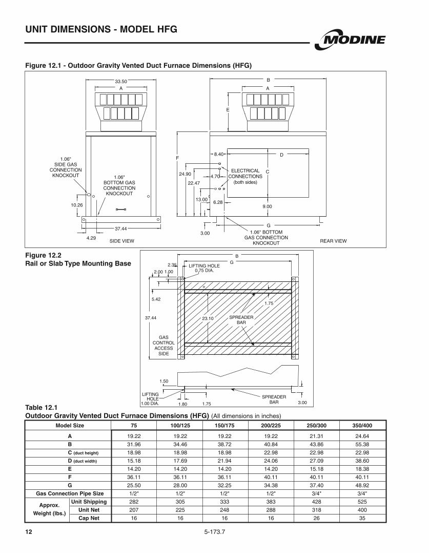
Figure 12.1 - Outdoor Gravity Vented Duct Furnace Dimensions (HFG)
Model Size 75 100/125 150/175 200/225 250/300 350/400
A 19.22 19.22 19.22 19.22 21.31 24.64
B 31.96 34.46 38.72 40.84 43.86 55.38
C (duct height) 18.98 18.98 18.98 22.98 22.98 22.98
D (duct width) 15.18 17.69 21.94 24.06 27.09 38.60
E 14.20 14.20 14.20 14.20 15.18 18.38
F 36.11 36.11 36.11 40.11 40.11 40.11
G 25.50 28.00 32.25 34.38 37.40 48.92
Gas Connection Pipe Size 1/2" 1/2" 1/2" 1/2" 3/4" 3/4"
Approx.
Unit Shipping 282 305 333 383 428 525
Weight (lbs.)
Unit Net 207 225 248 288 318 400
Cap Net 16 16 16 16 26 35
Table 12.1Outdoor Gravity Vented Duct Furnace Dimensions (HFG) (All dimensions in inches)
Figure 12.2Rail or Slab Type Mounting Base
4.29
1.06"BOTTOM GAS CONNECTION KNOCKOUT
1.06" BOTTOM GAS CONNECTION
KNOCKOUT
6.28
A33.50
10.26
1.06"SIDE GAS
CONNECTION KNOCKOUT
37.44
SIDE VIEW REAR VIEW
G
9.00
3.00
F
24.90
22.47
13.00
C
D8.40
4.70 CONNECTIONS (both sides)
E
A
B
BG2.35
0.75 DIA.
GAS
ACCESS SIDE
1.00 DIA.
37.44 23.10
1.50
1.80 1.75 3.00
1.755.42
2.00 1.00
SPREADER BAR
SPREADER BAR

5-173.7
Model Size 75 100/125 150/175 200/225 250/300 350/400
B 31.96 34.46 38.72 40.84 43.86 55.38
C (duct height) 18.98 18.98 18.98 22.98 22.98 22.98
D (duct width) 15.18 17.69 21.94 24.06 27.09 38.60
F 36.11 36.11 36.11 40.11 40.11 40.11
G 25.50 28.00 32.25 34.38 37.40 48.92
Q 10.95 10.95 10.95 11.58 11.58 11.58
R 7 7 7 9.9 9.9 9.9
Gas Connection Pipe Size 1/2" 1/2" 1/2" 1/2" 3/4" 3/4"
Approx. Unit Shipping 292 315 343 398 443 540
Weight (lbs.) Unit Net 217 235 258 303 333 415
UNIT DIMENSIONS - MODEL HFP
13
Figure 13.1 - Outdoor Power Exhausted Duct Furnace Dimensions (HFP)
Table 13.1Outdoor Power Vented Duct Furnace Dimensions (HFP) (All dimensions in inches)
Figure 13.2Rail or Slab Type Mounting Base
B
G2.35
0.75 DIA.
1.00 DIA.
37.44 23.10
1.50
1.80 1.75 3.00
1.755.42
2.00 1.00
SPREADER BAR
SPREADER BAR
DISCHARGE COVERPOWER EXHAUSTER
COMBUSTION AIR
CONNECTIONS
(both sides)
37.44
10.26
4.70
3.00
F
24.90
22.47
13.00
G
B
D8.40
C
9.00
33.50
4.29
6.28
9.50
R
1.723.00
2.67
4.16
Q
KNOCKOUT
GAS CONNECTION
1.06"BOTTOM
KNOCKOUTCONNECTIONBOTTOM GAS
1.06 KNOCKOUT
CONNECTION
SIDE GAS
1.06"
SIDE VIEW REAR VIEW
BOTTOM

5-173.714
SYSTEM UNIT DESIGN FEATURES
Indoor Gravity Vented (DGB/DCG)The indoor gravity vented duct furnace with blower, and/or cooling sections was designed for use with a building’s heating, heating/ventilating/cooling and make-up air systems. They have input ranges from 75,000 to 1,200,000 Btu/Hr and can operate on either natural or propane gas. The airflow ranges from 556 to 14,500 CFM and the airflow direction can be specified when ordering the unit. The unit can be provided with a cooling coil section with either a factory installed DX or chilled water cooling coil or the coil can be provided by others.
Figure 14.1 - Indoor Gravity Vented Duct Furnace with Blower Section (DBG)
Indoor Power Vented (DBP/DCP)Models DBP and DCP include all the items featured for Model DBG and DCG, but adds an integral power exhauster that allows for:
pipe possible.
in buildings with inadequate make up air.
cycle vent losses.
Indoor Separated Combustion (DBS/DCS)Model DBS and DCS builds upon the advantages of the Power Vented Model DBP and DCP, but is specifically designed for buildings with hostile environments, such as dirty or high humidity applications. This model features:
gasketed doors to seal components from the environment.
has plenty of fresh, clean air.
vent losses are essentially eliminated, further improving building efficiency.
Figure 14.3 - Indoor Separated Combustion Multiple Duct Furnace with Blower Section (DBS)
Outdoor Gravity Vented & Power ExhaustedThe outdoor duct furnace with blower, cooling, and/or downturn plenum sections was designed for use with a building’s heating, heating/ventilating/cooling and make-up air systems. They have input ranges from 75,000 to 1,200,000 Btu/Hr and can operate on either natural or propane gas. The airflow ranges from 556 to 14,500 CFM and the airflow direction can be specified when ordering the unit. The unit can be provided with a cooling coil section with either a factory installed DX or chilled water cooling coil or the coil can be provided by others.
Figure 14.4 - Outdoor Duct Furnace with Blower, Cooling Cabinet, and Downturn Plenum Sections (HPG)
Figure 14.5 - Outdoor Multiple Duct Furnace with Blower and Downturn Plenum Sections (HDG)
Figure 14.2 - Indoor Power Vented Duct Furnace with Blower Section and Cooling Coil Cabinet (DCP)
5-173.7
SYSTEM UNIT DESIGN FEATURES
15
Standard Features:All duct furnace standard features as listed on page 5, with the addition of the following:
polyester powder paint finish on exterior casing parts.
(outdoor units only).
electrical compartment.
(indoor units).
units).
Optional Features - Factory InstalledAvailable with all duct furnace optional features as listed on page 5, with the addition of the following:
® Aeropleat III (MERV 7) disposable, or 2" FARR® 30/30 (MERV 8) filters.
with a baked-on polyester powder paint finish.
performance ranges).
(standard on outdoor units).
sections.
only).
(outdoor units only).
position, or building management (0-10VDC or 4-20mA) damper actuators.
Accessories - Field Installed Available with all duct furnace accessory features as listed on page 5, with the addition of the following:
coolers only).
units only).
SYSTEM UNIT PERFORMANCE DATA
16 5-173.6
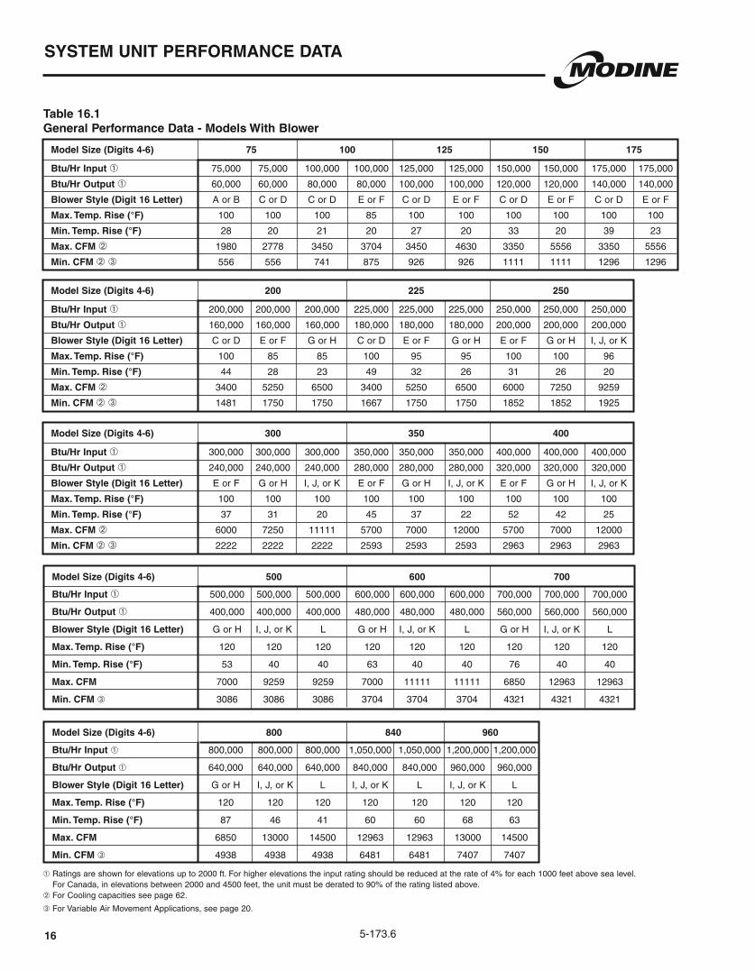
Table 16.1General Performance Data - Models With Blower
Model Size (Digits 4-6) 75 100 125 150 175
Btu/Hr Input ➀ 75,000 75,000 100,000 100,000 125,000 125,000 150,000 150,000 175,000 175,000
Btu/Hr Output ➀ 60,000 60,000 80,000 80,000 100,000 100,000 120,000 120,000 140,000 140,000
Blower Style (Digit 16 Letter) A or B C or D C or D E or F C or D E or F C or D E or F C or D E or F
Max. Temp. Rise (°F) 100 100 100 85 100 100 100 100 100 100
Min. Temp. Rise (°F) 28 20 21 20 27 20 33 20 39 23
Max. CFM ➁ 1980 2778 3450 3704 3450 4630 3350 5556 3350 5556
Min. CFM ➁ ➂ 556 556 741 875 926 926 1111 1111 1296 1296
Model Size (Digits 4-6) 200 225 250
Btu/Hr Input ➀ 200,000 200,000 200,000 225,000 225,000 225,000 250,000 250,000 250,000
Btu/Hr Output ➀ 160,000 160,000 160,000 180,000 180,000 180,000 200,000 200,000 200,000
Blower Style (Digit 16 Letter) C or D E or F G or H C or D E or F G or H E or F G or H I, J, or K
Max. Temp. Rise (°F) 100 85 85 100 95 95 100 100 96
Min. Temp. Rise (°F) 44 28 23 49 32 26 31 26 20
Max. CFM ➁ 3400 5250 6500 3400 5250 6500 6000 7250 9259
Min. CFM ➁ ➂ 1481 1750 1750 1667 1750 1750 1852 1852 1925
Model Size (Digits 4-6) 300 350 400
Btu/Hr Input ➀ 300,000 300,000 300,000 350,000 350,000 350,000 400,000 400,000 400,000
Btu/Hr Output ➀ 240,000 240,000 240,000 280,000 280,000 280,000 320,000 320,000 320,000
Blower Style (Digit 16 Letter) E or F G or H I, J, or K E or F G or H I, J, or K E or F G or H I, J, or K
Max. Temp. Rise (°F) 100 100 100 100 100 100 100 100 100
Min. Temp. Rise (°F) 37 31 20 45 37 22 52 42 25
Max. CFM ➁ 6000 7250 11111 5700 7000 12000 5700 7000 12000
Min. CFM ➁ ➂ 2222 2222 2222 2593 2593 2593 2963 2963 2963
➀ Ratings are shown for elevations up to 2000 ft. For higher elevations the input rating should be reduced at the rate of 4% for each 1000 feet above sea level. For Canada, in elevations between 2000 and 4500 feet, the unit must be derated to 90% of the rating listed above.
➁ For Cooling capacities see page 62.
➂ For Variable Air Movement Applications, see page 20.
Model Size (Digits 4-6) 500 600 700
Btu/Hr Input ➀ 500,000 500,000 500,000 600,000 600,000 600,000 700,000 700,000 700,000
Btu/Hr Output ➀ 400,000 400,000 400,000 480,000 480,000 480,000 560,000 560,000 560,000
Blower Style (Digit 16 Letter)
Max. Temp. Rise (°F) 120 120 120 120 120 120 120 120 120
Min. Temp. Rise (°F) 53 40 40 63 40 40 76 40 40
Max. CFM 7000 9259 9259 7000 11111 11111 6850 12963 12963
Min. CFM ➂ 3086 3086 3086 3704 3704 3704 4321 4321 4321
Model Size (Digits 4-6) 800 840 960
Btu/Hr Input ➀ 800,000 800,000 800,000 1,050,000 1,050,000 1,200,000 1,200,000
Btu/Hr Output ➀ 640,000 640,000 640,000 840,000 840,000 960,000 960,000
Blower Style (Digit 16 Letter)
Max. Temp. Rise (°F) 120 120 120 120 120 120 120
Min. Temp. Rise (°F) 87 46 41 60 60 68 63
Max. CFM 6850 13000 14500 12963 12963 13000 14500
Min. CFM ➂ 4938 4938 4938 6481 6481 7407 7407
17
SYSTEM UNIT PERFORMANCE DATA
5-173.6
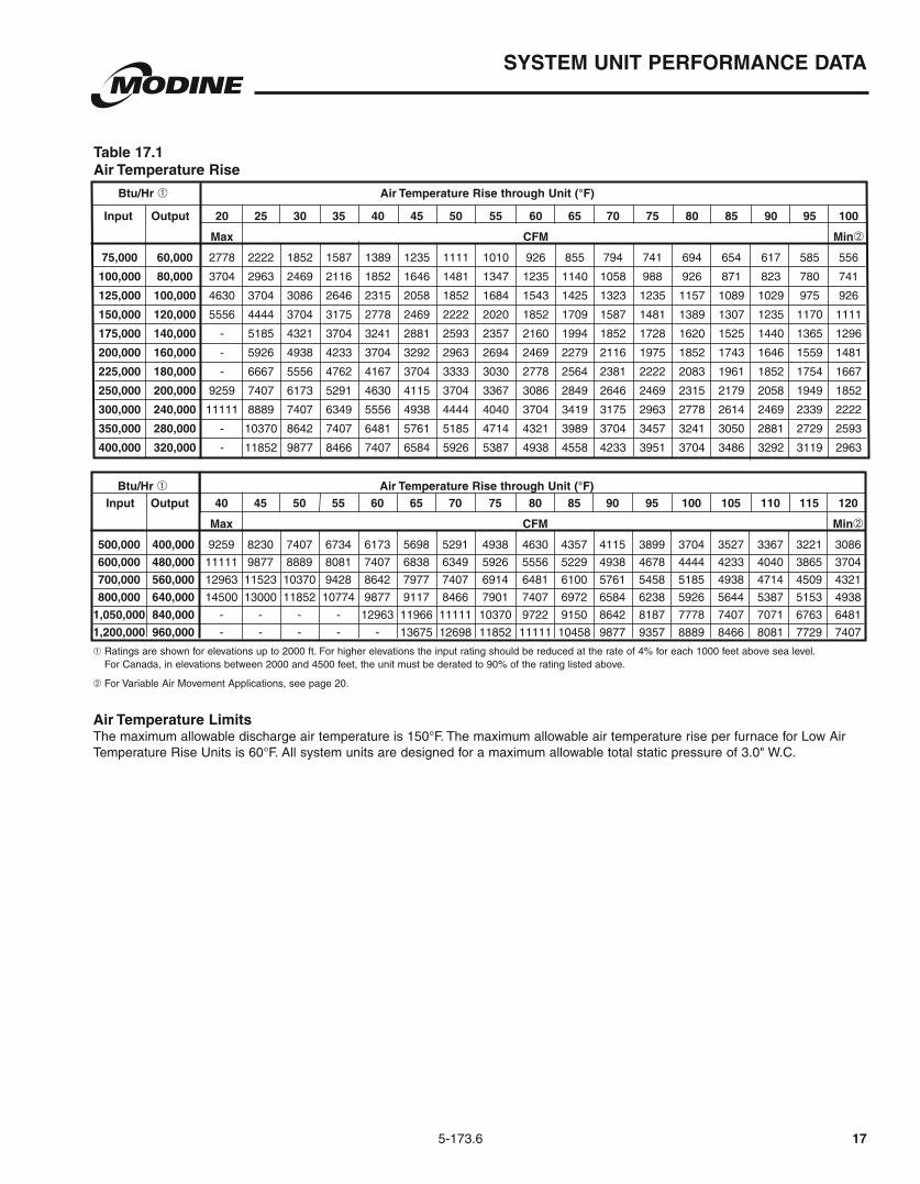
Table 17.1Air Temperature Rise
Input Output 20 25 30 35 40 45 50 55 60 65 70 75 80 85 90 95 100
Max CFM Min➁
75,000 60,000 2778 2222 1852 1587 1389 1235 1111 1010 926 855 794 741 694 654 617 585 556
100,000 80,000 3704 2963 2469 2116 1852 1646 1481 1347 1235 1140 1058 988 926 871 823 780 741
125,000 100,000 4630 3704 3086 2646 2315 2058 1852 1684 1543 1425 1323 1235 1157 1089 1029 975 926
150,000 120,000 5556 4444 3704 3175 2778 2469 2222 2020 1852 1709 1587 1481 1389 1307 1235 1170 1111
175,000 140,000 - 5185 4321 3704 3241 2881 2593 2357 2160 1994 1852 1728 1620 1525 1440 1365 1296
200,000 160,000 - 5926 4938 4233 3704 3292 2963 2694 2469 2279 2116 1975 1852 1743 1646 1559 1481
225,000 180,000 - 6667 5556 4762 4167 3704 3333 3030 2778 2564 2381 2222 2083 1961 1852 1754 1667
250,000 200,000 9259 7407 6173 5291 4630 4115 3704 3367 3086 2849 2646 2469 2315 2179 2058 1949 1852
300,000 240,000 11111 8889 7407 6349 5556 4938 4444 4040 3704 3419 3175 2963 2778 2614 2469 2339 2222
350,000 280,000 - 10370 8642 7407 6481 5761 5185 4714 4321 3989 3704 3457 3241 3050 2881 2729 2593
400,000 320,000 - 11852 9877 8466 7407 6584 5926 5387 4938 4558 4233 3951 3704 3486 3292 3119 2963
Btu/Hr ➀ Air Temperature Rise through Unit (°F)
Input Output 40 45 50 55 60 65 70 75 80 85 90 95 100 105 110 115 120
Max CFM Min➁
500,000 400,000 9259 8230 7407 6734 6173 5698 5291 4938 4630 4357 4115 3899 3704 3527 3367 3221 3086
600,000 480,000 11111 9877 8889 8081 7407 6838 6349 5926 5556 5229 4938 4678 4444 4233 4040 3865 3704
700,000 560,000 12963 11523 10370 9428 8642 7977 7407 6914 6481 6100 5761 5458 5185 4938 4714 4509 4321
800,000 640,000 14500 13000 11852 10774 9877 9117 8466 7901 7407 6972 6584 6238 5926 5644 5387 5153 4938
1,050,000 840,000 - - - - 12963 11966 11111 10370 9722 9150 8642 8187 7778 7407 7071 6763 6481
1,200,000 960,000 - - - - - 13675 12698 11852 11111 10458 9877 9357 8889 8466 8081 7729 7407
Btu/Hr ➀ Air Temperature Rise through Unit (°F)
➀ Ratings are shown for elevations up to 2000 ft. For higher elevations the input rating should be reduced at the rate of 4% for each 1000 feet above sea level. For Canada, in elevations between 2000 and 4500 feet, the unit must be derated to 90% of the rating listed above.
➁ For Variable Air Movement Applications, see page 20.
Air Temperature Limits
Temperature Rise Units is 60°F. All system units are designed for a maximum allowable total static pressure of 3.0" W.C.

5-173.718
MODEL NOMENCLATURE DESCRIPTION
Model Digit DescriptionsOnce the first six digits of the model number have been determined from model nomenclature, page 75, the pages 18 through 22 detail the specification of the additional model number digits. For the complete model nomenclature description see page 75.
Digit 7Heat Exchanger/Burner/Drip Pan Material (HE)Specifies the material for the heat exchanger, burner, and drip pan material. A 409 stainless steel heat exchanger and burner is recommended when the unit is installed downstream of a cooling coil or evaporative cooler, or when combined entering/return air to the unit is below 40°F.
A = Aluminized steel heat exchanger, burner, and drip panS = 409 Stainless steel heat exchanger and burner and an aluminized
steel drip panT = 409 Stainless steel heat exchanger, burner and drip pan
Digit 8Development Sequence (DS)Used for internal factory purposes to indicate the style of controls used on the unit.
F = Single stage gas controlsM = Two stage or electronic modulating
Digit 9Access Side (AS)Determines the side of the unit on which the controls are accessed. The control side is determined by looking in the discharge of the unit (air blowing into your face) and then specifying the access side (right or left hand). Includes access to gas controls, vent connections, electrical
discharge side of the unit for any optionally mounted discharge air components.
R = Right Hand
Digit 10Air Temperature Rise (ATR)Indicates the temperature range of each duct furnace.
For Indoor Gravity Vented Duct Furnaces:All Units are factory supplied with an air distribution baffle to direct the air toward the bottom of the heat exchanger where the heat exchanger tubes are the warmest. The baffle is required because of the low air volume (CFM) that is going through the duct furnace. This applies to units having an air temperature rise from 60 to 100°F. If the application will be operating with an air temperature rise less than 60°F it is recommended that the baffle be removed in the field to reduce pressure drop through the unit. Select N for this digit.
For Separated Combustion and Outdoor Duct Furnaces:High air temperature rise units (20°-100°F) include an air distribution baffle to direct the air toward the bottom of the heat exchanger where the heat exchanger tubes are the warmest. The baffle is required because of the low air volume (CFM) that is going through the duct furnace. The primary restrictor plate is factory sized to provide the 80% efficiency of the unit. High air temperature rise units are certified to be used at down to a 20°F rise, however, it is recommended to use them
temperature rise units do not include an air distribution baffle and thus the pressure drop of the unit is reduced. However, the primary restrictor plate is factory sized to provide the 80% efficiency of the unit.
For System Units:The primary restrictor is changed for separated combustion and outdoor units to provide the 80% efficiency of the unit. For gravity vented no changes are made. The blower section transition insures the proper distribution of the airflow across the heat exchanger.
Multiple Furnace Units 500-960For Models DBG500-960, Digit 10=N
Specifying the Air Temperature Rise for Variable Air Movement Applications (Separated Combustion and Outdoor Only)The selection of the unit should be based on the low speed temperature rise of the unit. Thus, if the high speed air temperature rise is 40°F and the low speed air temperature rise is 80°F, a high air temperature rise unit should be selected.H = High Temperature Rise - 20°-100°F
Digit 11Gas Type (GT)Determines the type of gas that will be used with the unit and the style of ignition controller. The type of gas determines the orifices used on the unit. The orifices are sized for elevations up to 2000 feet. For United States elevations of 2000 feet or greater, specify this at the time of ordering and the unit will be derated 4% per 1000 feet of elevation. In Canada for elevations of 2000 to 4500 feet, the unit is derated 10%.
N = Natural gas with continuous retry ignition controller A 100% shut-off with continuous retry ignition controller is used.
On a call for heat, the system will attempt to light the pilot for 70 seconds. If the pilot is not sensed for any reason, the ignition control will wait for approximately six minutes with the combination gas control closed and no spark. After six minutes, the cycle will begin again. After three cycles, some ignition controllers lockout for approximately one hour before the cycle begins again. This will continue indefinitely until the pilot flame is sensed or power is interrupted to the system.
P = Propane gas with continuous retry ignition controller (Gravity vented and separated combustion indoor units) A 100% shut-off with continuous retry ignition controller is used.
On a call for heat, the system will attempt to light the pilot for 70 seconds. If the pilot is not sensed for any reason, the ignition control will wait for approximately six minutes with the combination gas control closed and no spark. After six minutes, the cycle will begin again. After three cycles, some ignition controllers lockout for approximately one hour before the cycle begins again. This will continue indefinitely until the pilot flame is sensed or power is interrupted to the system.
P = Propane gas with lockout ignition controller (Outdoor units) For propane gas units, a 100% shut-off with lockout ignition
controller is used. On a call for heat, the system will attempt to light the pilot for 70 seconds. If the pilot is not sensed for any reason, the ignition control will lockout, the pilot gas valve will shut off and the sparking will cease. The system will not attempt to relight until power has been interrupted to the controls and the controls are reset via the thermostat.
Digit 12Gas Valve (GV)Determines the type of gas valve provided with each unit.
1 = Single-stage Single-stage gas controls utilize a single-stage combination gas
control, an ignition control, and a single-stage low voltage thermostat. The unit fires at 100% full fire based on a call for heat from a room thermostat (thermostat ordered separately).
2 = Two-stage Two-stage gas controls utilize a two-stage combination gas
control, an ignition control, and a two-stage low voltage thermostat. The unit fires at 50% fire on low stage or 100% fire on high stage of the unit based on the call for heat from either a room or duct thermostat (thermostat ordered separately).

5-173.7 19
MODEL NOMENCLATURE DESCRIPTION
4 = Electronic Modulation Electronic modulation gas controls utilize an electronic modulating/
regulating gas control, combination gas valve, an ignition control, modulating amplifier and either a modulating room thermostat or modulating duct thermostat with remote temperature set point
between 40% and 100% full fire. Requires the addition of either the room or duct electronic modulating thermostat.
When the duct thermostat is utilized, a room override thermostat can be added. When calling for heat, the room override thermostat provides full fire operation until the space temperature is satisfied. Control is then returned to the duct sensing control. In this situation, either the duct thermostat or the room override thermostat can call for heat.
5 = Electronic Modulation - Master (duct furnaces only) Used in higher Btu/Hr input applications where more than one
duct furnace is being used with electronic modulating gas controls. Allows one duct sensing thermostat to control the firing rate of the Master duct furnace and up to three Slave duct furnaces (See 6 = Slave). Utilizes the same controls as described in 4 = Electronic Modulation, except that a single duct furnace amplifier is replaced by a multiple furnace amplifier. The multiple furnace amplifier sends a signal to all of the gas valves so that they modulate at the same percentage. When the thermostat is satisfied, the amplifier cuts power to the combination gas valves of the Master unit and all Slave units, which prevents gas flow to both the main and pilot burners.
6 = Electronic Modulation - Slave (duct furnaces only) Requires one Master unit. The Slave furnace includes an
electronic modulating/regulating gas control, combination gas valve, and an ignition control, but no modulating amplifier and does not require a discharge air thermostat. The modulating gas valve receives the modulation percentage from the Master duct furnace. Up to three Slave duct furnaces can be connected to one Master unit.
7 = Electronic Modulation - 0-10 Vdc External Input Allows for control of the duct furnace firing rate by a Building
Management System (BMS). Utilizes an electronic modulating/regulating gas control, combination gas valve, an ignition control, modulating signal conditioner, and an inverted 0-10 Vdc input signal provided by a BMS (0 Vdc being high fire and 10 Vdc being low fire). The signal conditioner can modulate the gas flow between 40% and 100% full fire. When the BMS thermostat (supplied by others) is satisfied, the BMS heat contact (supplied by others) opens to cut power to the combination gas valve which prevents gas flow to both the main and pilot burners.
8 = Electronic Modulation - 4-20 mA External Input Allows for control of the duct furnace firing rate by a Building
Management System (BMS). Utilizes an electronic modulating/regulating gas control, combination gas valve, an ignition control, modulating signal conditioner, and an inverted 4-20 mA input signal provided by a BMS (4 mA being high fire and 20 mA being low fire). The signal conditioner can modulate the gas flow between 40% and 100% full fire. When the BMS thermostat (supplied by others) is satisfied, the BMS heat contact (supplied by others) opens to cut power to the combination gas valve which prevents gas flow to both the main and pilot burners.
Digit 13Additional Safety Switches (SS)Provides additional gas train safety devices.
A low gas pressure switch monitors the gas supply pressure ahead of all the gas controls and shuts off the electric supply to the ignition controller and combination gas valve if low gas pressure is experienced. This will shut off all gas flow to the burner. If the gas pressure to the unit is below the normal operating pressure, the burner could have
difficulty lighting properly. The switch has an automatic reset so that if the gas pressure is interrupted and then returned, the switch will automatically allow the unit to operate when gas conditions are returned to the allowable range of the pressure switch. A high gas pressure switch monitors the gas supply pressure downstream of all the gas controls and shuts off the electric supply to the ignition controller and combination gas valve if high gas pressure is experienced right before the manifold. This will shut off all gas flow to the burner. If the gas pressure to the unit is too high, the gas controls could be damaged and cause the unit to over fire. The switch has a manual reset so that if the gas pressure is too high, a service person must check the unit to make sure that none of the gas controls have been damaged by the high gas pressure and then reset the switch to allow the unit to operate when the gas conditions are returned to the allowable range of the pressure switch.If no additional safety switches are ordered, a standard control box may be selected for the gravity vented indoor duct furnace. This option is not available for indoor gravity vented system units, indoor separated combustion units or outdoor units, all which require the use of the premium Control box.
0 = No Additional Safety Switches (Premium Control Box)
2 = High Gas Pressure Switch (Premium Control Box)
4 = No Additional Safety Switches (Standard Control Box)
Digit 14Supply Voltage (SV)Indicates the supply voltage for the unit. For duct furnace units, this specifies the line voltage to 24V control transformer that will be provided with the unit. For system units, this specifies the control transformer voltage in addition to the blower motor voltage.
A = 115V/60Hz/1Ph E = 230V/60Hz/3PhB = 208V/60Hz/1Ph F = 460V/60Hz/3PhC = 230V/60Hz/1Ph G = 575V/60Hz/3PhD = 208V/60Hz/3Ph
Digit 15Transformer (TR)Indicates the size of the step-down transformer that converts line voltage power to low voltage for use with the gas controls. The transformer size is rated in volt-amps (VA). 40 VA transformers are Class II with integral fusing. 75 VA transformers are Class II with a 3.2A circuit breaker. 150 VA and 250 VA transformers include separate primary fusing. The size of the transformer should be specified based on Table 19.1.
1 = 40 VA 4 = 250 VA ➀2 = 75 VA ➀ 0 = None3 = 150 VA ➀
Table 19.1Gas Control Transformer Sizing
Note: When specifying a duct furnace, only the first fifteen digits of the model need to be specified. The additional eight digits are for System units.
➀ Digit 13 must equal 0,1,2, or 3➁ When Digit 14 = F or G, Digit 13 must equal 0,1,2, or 3
Model Size Unit Type Controlling Digit 15
Non Master Duct Furnace 1
Master Duct Furnace 1 Slave ➀ 2
Master Duct Furnace 2 Slaves ➁ 3
Master Duct Furnace 3 Slaves ➁ 3
Slave Duct Furnace 0
All System Units 2
500-800 All 3
Digit 12 = 1, 2, or 3 3
Digit 12 = 4, 7, or 8 4
75-400
840-960

20
Digit 16Blower Size and Bearing Type (BB)All System units are offered with at least two blower sizes available with the units 200,000 Btu/Hr input and greater offering three blower sizes (See Table 16.1). To determine the proper blower size, review the blower performance curves for the desired model size and insure that the required CFM and total static pressure (internal static pressure + external static pressure) are on the curve selected. For additional information on determining the proper blower size, review the Sizing and Selection Example on pages 34 and 35.
The blower assembly is available with either spider bearings or greaseable pillow block ball bearings. The spider bearing option includes blower mounted bearing brackets with ball bearings. Spider bearings are designed for use in low blower RPM and low motor horsepower applications. For units where Digit 16 is A, C, E, or G, the recommended limits are 1900 blower RPM and a 5 Hp motor. For units where Digit 16 = I, the required limits are 1200 blower RPM and a 10 Hp motor.
The pillow block bearing option includes two heavy duty pillow block bearing housings with internal ball bearings that are rigidly fastened to two 18 gauge minimum blower support channels. Pillow block bearings are available for all applications, but are required for high blower rpm and high motor horsepower applications that exceed the spider bearing limits.
A = 9-7 blower wheel with spider bearingsB = 9-7 blower wheel with pillow block bearingsC = 9-9 blower wheel with spider bearingsD = 9-9 blower wheel with pillow block bearingsE = 12-12 blower wheel with spider bearingsF = 12-12 blower wheel with pillow block bearingsG = 15-15 blower wheel with spider bearingsH = 15-15 blower wheel with pillow block bearingsI = 18-18 blower wheel with spider bearings under 15 HpJ = 18-18 blower wheel with pillow block bearings under 15 HpK = 18-18 blower wheel with pillow block bearings for 15 Hp & up
Digit 17 Motor Horsepower (HP)The required motor horsepower is determined by the required CFM and total static pressure (internal static pressure + external static pressure) when plotted on the blower performance curve selected. When determining the motor horsepower, always select the motor horsepower
the proper motor horsepower, review the Sizing and Selection Example on pages 34 and 35. Refer to pages 42 through 44 to determine if the selected motor has thermal overload protection. Motors that do not have internal thermal overload protection and all three phase motors, require a motor starter that is either factory installed or supplied by others and field installed.
B = 1/2 Hp M = 1/2 Hp with motor starterC = 3/4 Hp N = 3/4 Hp with motor starterD = 1 Hp P = 1 Hp with motor starterE = 1-1/2 Hp Q = 1-1/2 Hp with motor starterF = 2 Hp R = 2 Hp with motor starterG = 3 Hp S = 3 Hp with motor starterH = 5 Hp T = 5 Hp with motor starterI = 7-1/2 Hp W = 7-1/2 Hp with motor starterJ = 10 Hp X = 10 Hp with motor starterK = 15 Hp Y = 15 Hp with motor starter V = 20 Hp Z = 20 Hp with motor starter
Digit 18Motor Type (MT)Blower motors are available in Open Drip Proof (ODP), Totally Enclosed (TE) and High Efficiency (HE) ODP and TE. All motors are continuous duty, ball bearing type, Class “B” insulated with a rigid base. For the list of available motors based on supply voltage, refer to pages 42 through 44. These tables also include frame sizes, amp draws, service factors,
efficiencies, thermal overload protection, and weights. Motors that do not have internal thermal overload protection and all three phase motors require a motor starter that is either factory installed or supplied by others and field installed. Where applicable, all motors meet the Requirements of the Energy Policy Act of 1992.
Variable Air Volume ApplicationsUnits may be supplied with variable frequency drives for applications where variable air volume is required. The minimum air flow may be varied between 30 and 100% of the full speed airflow depending on the controls selection of the unit. Due to the extra restrictions of the controller all selections must be performed with the AccuSpec configuration software. Within AccuSpec, three variable frequency drive speed control changeover options are available:
1. Two speed which may be controlled by a manual high/low switch which may be factory mounted on the control panel or shipped loose for field installation, or by exhaust fan interlocks.
2. Floating building pressure sensing which utilizes a photohelic
amount of makeup air supplied to the space.3. Building management control which allows for an external signal of
Additionally, when the air mover supplied by others can provide variable air movement (i.e. two-speed units), the certified allowable minimum CFM of the System units can be 66% of the minimum listed CFM in Table 16.1 if the unit is applied as follows:1. The unit is provided with two-stage or electronic modulation gas
controls.2. The unit is provided with a factory installed discharge air controller.3. The system does not include a room thermostat.
The factory installed discharge air thermostat will prevent the unit from firing above the allowable 100°F rise when the unit is at or above the minimum CFM by monitoring the discharge air and going to low fire. A room thermostat, because it is located remote from the unit, could cause the unit to over-fire.
1 = Open Drip Proof (ODP)2 = ODP, High Efficiency (ODP HE)5 = Totally Enclosed (TE)6 = TE, High Efficiency (TE HE)
Digit 19Sheave Arrangement (SA)
sheave is shown in the Sheave Selection Tables on page 40.
Digits 20 and 21Air Control (AC)The Air Control digits determine the entering air locations to the blower, the type of damper motor, and the damper motor controller. If a damper motor is provided, it is mounted directly to the shaft of the fresh air damper. If fresh air and return air dampers are provided, the two dampers are
dampers are ultra low leak, Class II leakage resistance (less than 10 CFM/ft2 at 1" W.C.) dampers with self-compensating stainless steel side seals and santoprene and galvanized steel blade seals. All return air dampers, which are used for air balancing, shall be low leak, Class III leakage resistance (less than 40 CFM/ft2 at 1" W.C.) dampers with self-compensating stainless steel side seals and santoprene blade seals. All damper motors are spring return (except Air Control HP), so when the damper motor is de-energized the fresh air opening is closed. All two-position damper motors contain one normally open and one normally closed end switch.
The Fresh Air and Return Air openings are defined as follows:The fresh air opening is defined as a back inlet to the unit. The return air opening is defined as a bottom inlet to the unit.
5-173.6
MODEL NOMENCLATURE DESCRIPTION

5-173.7
MODEL NOMENCLATURE DESCRIPTION
AA = Return Air Opening This configuration is typically used for heating only units in which
100% of the air is recirculated from the space. In this configuration, the unit does not contain a damper and the back of the unit does not contain an opening for outside air.
BA = Fresh Air Opening This configuration is typically used for heating only units in which
100% of the air is recirculated from the space. In this configuration, the unit does not contain a damper and the bottom of the unit does not contain an opening for return air.
CA = Fresh Air and Return Air Openings This configuration is typically used for heating only units in which
the return air will be brought to the unit from both the bottom and the back of the unit. In this configuration, the unit does not contain a damper in either opening.
DA = Fresh Air Dampers with Two-Position Damper Motor with No Return Air
This configuration is typically used for 100% make-up air units. In this configuration, the bottom of the unit does not contain an opening for return air.
EA = Fresh Air and Return Air Dampers with Two-Position Damper Motor
This configuration is typically used for heating and make-up air units that require 100% outside air during the daytime (or occupied mode) and 100% return air during the evening (or unoccupied mode). The damper motor can be energized by a switch (day/night, occupied/unoccupied, etc.) to control the damper position.
EQ = ASHRAE Cycle I - Fresh Air and Return Air Dampers with Two-Position Damper Motor with Warm-Up Thermostat
This configuration is typically used for heating and make-up air units that require 100% outside air during the daytime (or occupied mode) and 100% return air during the evening (or unoccupied mode). The damper motor can be energized by a switch (day/night, occupied/unoccupied, etc.) to control the damper position. The warm-up thermostat is provided so that when the unit is switched into the 100% outside air mode, the return air temperature is monitored and prevents the fresh air damper from opening until the temperature of the return air has reached the desired set point (usually 5°F below the room temperature).
FA = Fresh Air Dampers and Return Air Opening with Two-Position Damper Motor
This configuration is typically used for heating and make-up air units that require a mix of outside air and return air during the daytime (or occupied mode) and 100% return air during the evening (or unoccupied mode). The damper motor can be energized by a switch (day/night, occupied/unoccupied, etc.) to control the damper position.
GA = Fresh Air and Return Air Dampers with Modulating Damper Motor with 0-10 Vdc External Input Signal
This configuration is typically used for heating and make-up air units that require a mix of outside air and return air with the percentages being controlled by a Building Management System (BMS). The BMS would provide the control of the dampers through a 0-10Vdc external input signal.
GB = Fresh Air and Return Air Dampers with Modulating Damper Motor with 4-20 mA External Input Signal
This configuration is typically used for heating and make-up air units that require a mix of outside air and return air with the percentages being controlled by a Building Management System (BMS). The BMS would provide the control of the dampers through a 4-20 mA external input signal.
GC = Fresh Air and Return Air Dampers with Modulating Damper Motor with Minimum Positioner
This configuration is typically used for heating and make-up
air units that require a mix of outside air and return air with the percentage of outside air being the same at all times. Includes a factory mounted manual positioner in the blower section electrical cabinet that can be field set for the desired outside air percentage. When the unit is energized, the outside air damper would open to the preset percentage.
GD = Fresh Air and Return Air Dampers with Modulating Damper Motor with Remote Positioner
This configuration is typically used for heating and make-up air units that require a mix of outside air and return air with the percentage of outside air being changed throughout the day. The remote positioner is field mounted in the space so that the percentage of outside air can be manually changed from the space depending on the ventilation requirement. If a remote monitoring panel is ordered, the remote positioner can be mounted on the panel. When the unit is energized, the outside air damper would open to the preset percentage.
GE = Fresh Air and Return Air Dampers with Modulating Damper Motor for Three Positions
This configuration provides three positions (100% return air, a
outside air) of air control. It is typically used for heating and make-up air units that require 100% return air during the evening, a mix of outside air and return air during most of the daytime, and 100% outside air when an exhaust fan is operating. Includes a factory mounted manual positioner in the blower section electrical cabinet that can be field set for the desired outside and return air percentage. Also includes terminal strip contacts to provide 100% outside air when an exhaust fan contact (by others) is closed.
GF = Fresh Air and Return Air Dampers with Modulating Damper Motor with A350P Proportional Temperature Controller
This configuration is typically used for heating and make-up air units that require a mix of outside air and return air with the percentage of outside air being controlled by a proportional temperature controller. The proportional temperature controller monitors the temperature of the mixed fresh and return air and is usually set at 55°F to allow for first stage cooling. The proportional temperature controller will open the fresh air dampers and simultaneously close the return air dampers to maintain the preset mixed air temperature in the blower section of the unit. The fresh air dampers will modulate from zero to 100% open depending on the mixed air temperature. Includes a factory mounted A350P proportional temperature controller in the blower section electrical cabinet that can be field set for the desired outside air position with the sensing bulb factory mounted in the mixed air stream of the blower section.
GG = Fresh Air and Return Air Dampers with Modulating Damper Motor with Minimum Positioner and A350P Proportional Temperature Controller
This configuration is typically used for heating and make-up air units that require a mix of outside air and return air with the percentage of outside air being controlled by proportional temperature controller with a required percentage of outside air at all times. The minimum positioner sets the minimum percentage of outside air that will be provided at all times. The proportional temperature controller monitors the temperature of the mixed fresh and return air and is usually set at 55°F to allow for first stage cooling. The proportional temperature controller will open the fresh air dampers and simultaneously close the return air dampers to maintain the preset mixed air temperature in the blower section of the unit. The fresh air dampers will modulate from the minimum percentage (set by the minimum positioner) to 100% open depending on the mixed air temperature. Includes a factory mounted minimum positioner and A350P proportional temperature controller in the blower section electrical cabinet that can be field set for the desired outside air position with the sensing bulb factory mounted in the mixed air stream of the blower section.
21
5-173.722
MODEL NOMENCLATURE DESCRIPTION
GH = Fresh Air and Return Air Dampers with Modulating Damper Motor with Remote Positioner and A350P Proportional Temperature Controller
This configuration is typically used for heating and make-up air units that require a mix of outside air and return air with the percentage of outside air being controlled by proportional temperature controller with a required percentage of outside air at all times. The remote positioner (field mounted) sets the minimum percentage of outside air that will be provided at all times. The proportional temperature controller monitors the temperature of the mixed fresh and return air and is usually set at 55°F to allow for first stage cooling. The proportional temperature controller will open the fresh air dampers and simultaneously close the return air dampers to maintain the preset mixed air temperature in the blower section of the unit. The fresh air dampers will modulate from the minimum percentage (set by the remote positioner) to 100% open depending on the mixed air temperature. Includes a factory mounted A350P proportional temperature controller in the blower section electrical cabinet that can be field set for the desired outside air position with the sensing bulb factory mounted in the mixed air stream of the blower section. If a remote monitoring panel is ordered, the remote positioner can be mounted on the panel.
GJ = Fresh Air and Return Air Dampers with Modulating Damper Motor with Fresh Air Enthalpy Controller
This configuration is typically used for heating and make-up air units that require first stage ventilation in the summer. The load on the mechanical cooling system is reduced by mixing the percentage of outside air and return air based on the outside enthalpy, which is a combination of the temperature and humidity. As the enthalpy of the outside air decreases, the outdoor air damper opens to bring in more outside air to reduce the cooling load of the building. The enthalpy controller includes
GK = ASHRAE Cycle II - Fresh Air and Return Air Dampers with Modulating Damper Motor with Minimum Positioner, A350P Proportional Temperature Controller, and Warm-Up Thermostat
Identical to Air Control GG with the addition of a factory installed warm-up thermostat. The warm-up thermostat is provided so that when the unit is switched into the daytime mode, the return air temperature is monitored and prevents the fresh air damper from opening until the temperature of the return air has reached the desired set point (usually 5°F below the room temperature).
GM = ASHRAE Cycle II - Fresh Air and Return Air Dampers with Modulating Damper Motor with Remote Positioner, A350P Proportional Temperature Controller, and Warm-Up Thermostat
Identical to Air Control GH with the addition of a factory installed warm-up thermostat. The warm-up thermostat is provided so that when the unit is switched into the daytime mode, the return air temperature is monitored and prevents the fresh air damper from opening until the temperature of the return air has reached the desired set point (usually 5°F below the room temperature).
GN = ASHRAE Cycle III - Fresh Air and Return Air Dampers with Modulating Damper Motor with A350P Proportional Temperature Controller, and Warm-Up Thermostat
Identical to Air Control GF with the addition of a factory installed warm-up thermostat. The warm-up thermostat is provided so that when the unit is switched into the daytime mode, the return air temperature is monitored and prevents the fresh air damper from opening until the temperature of the return air has reached the desired set point (usually 5°F below the room temperature).
HP = Fresh Air and Return Air Dampers with Floating Damper Motor with Space Pressure Controller
This configuration is typically used to maintain a slightly positive pressure in the building to reduce infiltration. It is also used to provide heating and make-up air for buildings that have multiple exhaust loads that cannot be interlocked to one make-up air unit. Includes a field installed photohelic pressure controller, relay, outside air pressure sensor, and 50 feet of 1/8" tubing to connect to the sensor. The photohelic pressure controller allows
and includes an indicator showing the actual building pressure. The fresh air and return air dampers float to keep the building pressure between the desired limits. The limits are field
de-energized, a relay contact closes the outside air dampers.
JA = Manual Fresh Air and Return Air Dampers This configuration is typically used for heating and make-up air
units for which the damper position will never change. Includes a manual stop to hold the dampers open.
KA = Manual Fresh Air Dampers and Return Air Opening This configuration is typically used for heating and make-up air
units for which the damper position will never change. Includes a manual stop to hold the dampers open.
Digit 22Evaporative Cooling (EC) (Outdoor Units)The factory installed evaporative cooling option provides an economical means of supplying conditioned air to a space. Available in two media types and depths. For additional information on specification and selection, see pages 69-70.
0 = No Evaporative Cooler3 = 6'' Munsters®
4 = 12'' Munsters®
5 = 6'' Munsters®
6 = 12'' Munsters®
B - 1 C - 6" D - 12"
Digit 23Cooling Coil (CC)For units with the cooling cabinet option (model sizes 75-400 only), this option indicates if the cooling coil is to be provided factory installed or by others. For determining the maximum size of the cooling coil and dimensions of the cabinet, see page 62.0 = Coil By Others1 = Factory Installed Coil

5-173.7
THIS PAGE INTENTIONALLY LEFT BLANK
23

24
OPTIONS - FACTORY INSTALLED
Figure 24.1Factory Mounted Option Locations
1. Discharge Thermostat
3. High Gas Pressure Switch4. Power Exhauster5. Timed Freeze Protection6. Ignition Controller7. Combustion Air/Exhaust Cap8. Control Relay9. Time Delay Relay
11. Power Exhauster Relay12. Furnace Supply Power Terminal Strip13. Control Step Down Transformer14. Control Relay
16. Dead Front Disconnect Switch17. Step Down Transformer Fuses 18. Step Down Transformer 19. Factory Installed Minimum Positioner
22. Return Air Fire Stat23. Blower Housing24. Pillow Block Bearings25. Blower Motor26. Filters27. Fresh Air Damper28. Enthalpy Sensor (Outdoor only)29. Rainhood and Birdscreen (Outdoor only)30. Direct Drive Damper Actuator31. Enthalpy Controller
33. Return Air Damper34. Proportional Temp Controller Sensor35. Motor and Blower Vibration Isolation36. Blower Support37. Convenience Outlet38. Blower Door Switch39. Dirty Filter Switch40. Motor Starter/VFD control
41. Mild Temperature Thermostat (Outdoor only)42. Proportional Temp Controller43. Warm-Up Stat44. Blower Supply Power Terminal Strip45. Service Switches46. Electronic Modulating Amplifier47. Electronic Modulating Gas Valve48. Air Flow Proving Switch
50. Supply Air Fire Stat51. Main Gas Valve52. Burner Box53. Direct Drive Damper Actuator (Outdoor only)54. Discharge Damper (Outdoor only)55. Differential Pressure Switch (Sep. Comb. only)56. Blocked Vent Safety Switch57. Control Terminal Board58. Energy Cut off Switch
NOTE: Common blower cabinet for all above units.
STANDARD UNITS
PREMIUM UNITS12300
FM
R
DPRESSUREOPERATED
SWITCH504H
ADDISONA
M1
WPRESSURE
50100150200
350
250
mm.W.C.
246810
14
IN.
12300
FM
R
PRESSUREOPERATED
SWITCH504H
ADDISONA
M1
WPRESSURE
50100150200
350
250
mm.W.C.
246810
14
IN.
98
466
12
46
8
13
48
57
6
9
13
475851
49
52
2
3
50
5
10
56
1
Outdoor System Unit
Indoor Gravity Vented Duct Furnace
9
52 51
11
1
2 3
4 55
8 1213
47
46
48
49 50
5
610
Indoor Separated Combustion Duct Furnace
5-173.6
Units with StandardControl Panel
Units with Premium Control Box
13
48
6
466
8
57
9
13
49
2
3
50
5
4
1
10
98
12
46
47555152
12300
FMR
LISTEDPRESSUREOPERATED
SWITCH504H
ADDISONIL. U.S.A.
MODELRLGP-A
M1
LOWPRESSURE
50100150200
350
250
mm.W.C.
246810
14
IN.
12300
FMR
LISTEDPRESSUREOPERATED
SWITCH504H
ADDISONIL. U.S.A.
MODELRLGP-A
M1
LOWPRESSURE
50100150200
350
250
mm.W.C.
246810
14
IN.
12
34
56
A1010 Amplifier
89
1011
14
G HT
PV
MV
LEDTH
PV/MV
GNDTR
SENSE
Indoor Power Vented Duct Furnace
25
OPTIONS
The following list details the factory installed options available. For the location of all options, see Figure 24.1Filters
filters are: 1” Permanent 2” Farr® Aeropleat (MERV 7)
2” Permanent 2” Farr® 30/30 (MERV 8)
Double Wall ConstructionIncludes a 22 gauge aluminized steel metal liner covering 1-1/2# density insulation (ordered separate for indoor units). The metal unit allows the interior of the unit to be wiped down for cleaning and conforms to ASHRAE Standard 62-2001 - Ventilation for Acceptable Indoor Air Quality. Available for Blower, Cooling and Downturn sections where applicable.
Motor and Blower Vibration Isolation (35)Includes rubber-in-shear grommets to isolate the blower and motor assembly from the casing. The blower duct connection is not rigidly mechanically fastened and the 1/4” thick gasketing around the duct transition provides vibration isolation.
Air Flow Proving Switch (48)The air flow proving switch is factory installed in the duct furnace
differential between the duct furnace and the atmosphere. The purpose of the air flow proving switch is to cut power to the gas controls if a positive pressure is not measured by the switch. This could be caused by a lack of air movement through the heat exchanger.Note: The air flow proving switch will prevent any heat exchanger
warm-up because the gas controls cannot be energized until air flow is proven.
Timed Freeze Protection (5)The timed freeze protection system is factory installed in the duct
factory installed in the discharge air stream. On initial start-up, the timed delay in the system allows the unit to go through the normal ignition sequence. The timed delay is an automatic reset switch and
this period, the discharge air sensor will sense the cold air and will shut down the entire unit.
Mild Temperature Thermostat (41)The mild temperature thermostat is factory installed in the blower electrical section for System Units and it senses outdoor air temperature. The purpose of the mild temperature thermostat (45°-75°F
that the unit does not cycle in an attempt to maintain a very low air temperature rise. The mild temperature thermostat is usually set at approximately 60°F or 5°-10°F below the duct or room thermostat. For Indoor units and Outdoor non-system units, the mild temperature
in the inlet air stream.
For Outdoor 500-960 field installed mild temperature thermostats
individual duct furnaces based on outside air temperature to reduce the amount of gas control cycling. One, two, or three mild temperature stats can be used based on the number of duct furnaces.
Supply Air Fire Stat (50)The supply air fire stat is factory installed in the duct furnace electrical
elevated temperatures (200°F) in the supply air, the manual reset switch shuts down the entire unit.
Return Air Fire Stat (22)The return air fire stat is factory installed in the blower section electrical
temperatures (120°F) in the return air, the manual reset switch shuts down the entire unit.
Extended Grease Lines (21) (Requires Blower Pillow Block Bearings)Includes factory installed grease lines extending from the blower bearings to the outside of the unit cabinet. Also includes zerk fittings for applying grease. Requires grease for initial start-up.
Control Relay (8)Includes a 24v relay coil with double-pole, double throw (DPDT) contacts for sequence of operation control switching. The two normally open and two normally closed contacts are rated with a maximum of 30 amps @ 115V/1Ph. The relay is mounted in either the duct furnace
Convenience Outlet (37)Includes a factory installed 15 amp @ 115V ground fault circuit interrupter (GFCI) service receptacle in the blower section of the unit. Requires a separate field connected 115V/1Ph power supply.
Blower Door Safety Switch (38)Includes a safety switch that breaks power in the unit low voltage control circuit when the blower door is opened.
Manual Reset High Limit Switch (49)The manual reset high limit switch is factory installed in place of the standard automatic reset high limit switch located in the duct furnace
of the inlet air, etc., the manual reset switch prevents the unit from cycling on the high limit for a prolonged period of time. To prevent building freezing, this option is not recommended for heating units that are the only source of building heat.
Time Delay Relay (9) (Duct Furnace Units Only, Standard on System Units)The time delay relay is factory installed in the duct furnace electrical
operation. On a call for heat, the blower is energized (control by others) at the same time as the gas controls. The optional time delay relay allows the gas controls to operate for approximately 30 seconds before the blower starts. This allows the heat exchanger a warm-up period so that the initial delivered air is not cool. The time delay relay also keeps the motor running for approximately 30 seconds after the call for heat has been satisfied to remove the residual heat from the heat exchanger.
2-Position Damper Limiter (Air Control EA and FA Only)Mechanically prevents the outside air damper from opening completely and results in a fixed outside/return air percentage any time the dampers are energized. The outside air percentage must be specified when ordering and cannot be changed in the field.
Dirty Filter Pressure Switch (39)
in the blower section. The switch monitors the filter pressure drop to determine if the filters are dirty. Required for remote monitoring panels with a dirty filter light.
Evaporative Cooling and Power Exhausted Step Down Transformers (18)Evaporative cooling units which have a supply voltage of 208V/1Ph, 208V/3Ph, 460V/3Ph, or 575V/3Ph or power exhausted units that have 460V/3Ph, or 575V/3Ph require a step down transformer for the pump motor. Refer to electrical data for transformer sizing.
Discharge Air Damper (Downturn plenum outdoor units only) (54)Used in 100% make-up air applications to prevent the building air from infiltrating back into the unit. Includes a factory installed discharge air damper and two-position damper motor located in the downturn plenum. The discharge damper is an ultra low leak, Class II leakage resistance (less than 10 CFM/ft2 at 1” W.C.) damper with self-compensating stainless steel side seals and santoprene and galvanized steel blade seals. The damper motor includes end switches to prevent the blower from operating when the damper is not open.
5-173.6

5-173.7
Variable Frequency Drive (40)
minimum air flow may be varied between 30 and 100% of the full speed airflow depending on the controls selection of the unit. The control changeover options are two speed, floating building pressure sensing, and building management control.
Circuit Analyzer (See Figure 26.1)Used to quickly assist service personnel in trouble shooting. Monitors
as a point of operation is passed and proven. If any light is not lit, that is the point where failure occurred. Circuit analyzer is mounted on the door of the blower section electrical compartment. There are 6 and 10 point analyzers available. Select circuit analyzer appropriate to the number of points to be monitored. The following points are available:
Field Installed Disconnect SwitchesIncludes a NEMA 3R disconnect switch to cut power to all electrical components of the unit before servicing. Non-fusible and fusible switches available. For fusible switches, includes blades and fuse holders (fuses not included). Provisions for Class “H” time delay fuses.
26
OPTIONS
SERVICE SWITCHES
POWER
STRIP
DEAD FRONT DISCONNECT
SWITCH
TWO-SPEED MOTOR
STARTER
PRESSURE SWITCH
EXTENDED GREASE
FITTINGS
1/4" PERIMETER GASKETED
CONNECTION
CONVENIENCE
SAFETY SWITCHBOTTOM
SUPPORTED
MOTOR
DIRECT DRIVE DAMPER
ACTUATOR
RACKMOTORMOTOR SHEAVE
EXTENDED GREASE
SUPPLY POWERWIRING TERMINALS
(SEE WARNING)
BLOWER SECTIONELECTRICAL
COMPARTMENTACCESS DOOR
DISCONNECTSWITCH HANDLE
OPERATIONINSTRUCTION
LABEL
BLOWER SECTIONELECTRICAL
COMPARTMENTSTAND-OFF PANEL
DISCONNECTSWITCH HANDLESHOWN IN THE"ON" POSITION
Point To Be Analyzed Required Control Device
24V Transformer Power None
Door Switch Door Switch
Smoke Detector Smoke Detector
Freeze Protection Freeze Thermostat
Fire Stat Fire Stat
Amplifier Power Electronic Modulation Controls
Call For Heat None
Air Flow Proving Air Flow Proving Switch
Mild Temp Stat Mild Temp Thermostat
High Gas Pressure High Gas Pressure Switch
Burner On None
High Stage Heat Two-Stage Controls
Warm Up Stat Warm Up Thermostat
Dampers Open Two Position Dampers
Mod Supply Air Modulating Dampers
Dampers Opening Floating Dampers
Dampers Closing Floating Dampers
Blower On None
Blower On (High) Two-Speed VFD
Evap On Evaporative Cooler
Cool On Control Relay (Cooling Circuit By Others)
Figure 26.1Circuit Analyzer
Figure 26.2Electrical Section
Figure 26.3Electrical Section Wiring
Figure 26.4Blower Section
Factory Installed Dead Front Disconnect Switches(See Figures 26.2 and 26.3)Includes a disconnect switch that must be turned “OFF” before entry to the electrical control cabinet can be obtained. Switch can be manually overridden for purposes of servicing the unit. Factory installed in the door of the blower electrical compartment. Fusible and circuit breaker switches available. For fusible switches, includes blades and fuse holders (fuses not included). Provisions for Class “J” time delay fuses.

5-173.7
Type Installation Description
Room Field White Rogers 1C20-101: 50°-90°F, 1.0A @ 24VAC
Room Field White Rogers 1C26-101: 50°-90°F, 1.0A @ 24VAC, Heat/Off & Fan On/Auto switches
Room - Field Robertshaw 300-225 7-day programmable thermostat. One heat and one cool stage; Fan Programmable On/Auto and Heat/Off/Cool/Auto System Switching; 2 to 4 events per day; Override feature; Figure 27.1 One auxiliary output terminal.
Room - Digital Field Honeywell TH5220D1029 digital non-programmable room stat with switching - (With Switching) range 40-90°F
Room - Field Robertshaw 300-229 7-day programmable thermostat. Two heat and two cool stages; Programmable Fan On/Auto and Heat/Off/Cool/Auto System Switching; 2 to 4 events per day; Override Figure 27.1 feature; One auxiliary output terminal.
Duct ➀ ➁ Factory or Field Honeywell T678A1015 - 0-100°F temperature range; 20 foot capillary; 8 amp rating @ 120V.
Duct Factory Johnson Controls Electronic Temp Control with factory installed SET189A-600R Temp Sensor. Figure 27.3 Shipped loose A350 temp selector and one (up to two) S350 Stage Adder.
Duct Field Johnson Controls Electronic Temp Control with field installed SET189A-600R Temp Sensor, Figure 27.3 A350 temp selector and one (up to two) S350 Stage Adder.
Duct Factory Maxitrol Discharge Air Sensor TS121 and Mixing Tube MT2R-12. Range 55-90°F. REQUIRES Figure 27.4 THE ADDITION OF THE SET POINT ADJUSTER - Maxitrol TD121 (See below).
Duct Field Maxitrol Discharge Air Sensor TS121 and Mixing Tube MT1R-12. Range 55-90°F. REQUIRES. Figure 27.4 THE ADDITION OF THE SET POINT ADJUSTER - Maxitrol TD121 (See below).
Figure 27.4
Room Override Field Can only be used with Maxitrol Duct Sensing System described above. Includes Maxitrol T115 Figure 27.4 room override stat. Temperature range 40-90°F.
Room - Figure 27.2 Field Maxitrol Selectra-Stat T120. Temperature range 60-85°F.
27
THERMOSTATS
Table 27.1 Factory and Field Installed
Single-stage Thermostats
Two-stage Thermostats
Electronic Modulating Gas Control Thermostats
Figure 27.4Maxitrol Duct Sensing Components
MT2-12 TS-121MIXING TUBE AND SENSOR
TD-121SET POINT ADJUSTER
T115OVERRIDE STAT
Figure 27.17-Day Programmable Thermostat
Figure 27.2Maxitrol Selectra-stat
Figure 27.3System 350 Components
➀ For non-cooling indoor gravity and power vented units, the thermostat is factory installed with sensing tube shipped on the side of the unit for field installation.
➁ One or two duct stats can be used on Model Sizes 500-960 based on gas valve selection.

5-173.728
FIELD INSTALLED ACCESSORIES
Rainhood and Birdscreen (29) (Outdoor only)Used to prevent entry of rain into the fresh air opening of the unit. Fully assembled and constructed of 20 gauge polyester powder painted aluminized steel with internal baffles and a meshed bird screen. Not for use with units with evaporative coolers.
7-Day Electronic Programmable Time Clock7-day/24-hour digital programmable time clock that features 7-day power-outage carryover of program and time of day without the use of batteries. The control allows for simple and inexpensive control of functions such as automatic temperature setback (requires setback thermostat purchased separately), reduction of outside air during periods when the building is not occupied, and switching main supply fans from continuous to intermittent operation. As a 24-hour control, the same ON/OFF program is utilized each day of the week, Saturday and/or Sunday, or any other day may be skipped. When schedules vary from day to day, the 7-day programming capability allows for a different schedule each day of the week, with up to 16 set points available. Requires a 115V/1Ph power supply by others.
7-Day Econo-TimerThe 7 day push pin style appliance timer allows for simple and inexpensive control of functions such as automatic temperature setback (requires setback thermostat purchased separately), reduction of outside air during periods when the building is not occupied, and switching main supply fans from continuous to intermittent operation. The time clock shall be mounted in a suitable enclosure (by others) complying with the requirements of all local codes and the NEC. The terminals of the time clock are line voltage so the base must be located in a NEMA 1 enclosure (by others). Requires 115V/1Ph power supply by others.
Smoke Detector
detect the presence of smoke in the duct. Once the smoke is sensed, the smoke detector will de-energize the unit. Must be installed indoors and duct velocity range must be between 500 to 4000 feet per minute. Double pole, double throw contacts, manual reset. For duct widths of up to 1-1/2 feet. For greater duct widths, smoke detector tube extensions are available for up to 8 foot wide ducts.
Gas Pressure RegulatorFisher Type S-100, 3/4 inch pressure regulator for 5 to 10 PSI inlet pressure capacity, 30 MBH to 400 MBH. Natural or propane gas.
Thermostat GuardsClear plastic for room thermostats. Guard is locking type and comes complete with two keys.
Summer/Winter SwitchAllows a choice of fan operation of the duct furnace/make-up air unit, the summer/winter toggle switch kit is available for field installation. In the summer position, the fan runs continuously for ventilation and the heating circuit is disabled. In the winter position for single-stage and two-stage gas control units, the thermostat will cycle the fan and the heating circuit. In the winter position for mechanical modulating and electronic modulating gas control units, the fan runs continuously for ventilation and the thermostat will cycle the heating circuit.
4' Extended Vent Kit (Outdoor only)Gravity Vented UnitsIncludes the components required for the modification of the standard combustion air/vent cap to allow the vent cap to be extended approximately four feet above the unit. Includes the vent pipe, vent cap, and secondary restrictor.
Power Exhausted UnitsIncludes the components required for the modification of the standard vent discharge cover to allow the vent cap to be extended approximately four feet above the unit. Includes the vent pipe, vent cap, 90° elbow, exhaust collar, and strap clamp.
Remote Monitoring PanelsUsed to control the operation of the make-up air unit. Standard remote panels include 2 lights (Heat On and Blower On) and a Summer/Off/Winter Switch. Custom remote panels are available, see page 59.
Roof Curbs (Outdoor only)16" high roof curb is constructed of 16 gauge galvanized steel and designed to support the system units. The curb does not extend to the optional evaporative cooler section. The roof curb is shipped knocked down for field assembly and includes 1” x 4” nailer strips and curb gasket material. For flat roofs only and available insulated or uninsulated.
Discharge Air Connections and/or Return Air Connections (Outdoor only)
return air ductwork connections to be made before the unit arrives at

5-173.7 29
CONTROL APPLICATIONS
Various control application methods are illustrated on this page and on the following pages as guides to the types of systems available and the components necessary to obtain the desired control function. Under each application category, such as, “Heating Only”, several methods of operation are described. These methods are labeled as “A”, “B”, “C”, etc. The required components for a particular method of control are labeled in each diagram with the appropriate corresponding letter designation. As an example, under “Heating Only”, using method “A”, single-stage control, the required components would be: Single-Stage Heating Controls and a Single-Stage Room Thermostat. Method “B” would use the components labeled “B”. An operating description of each application method is given beneath the appropriate illustration.
Method A Single-stage heating of a space requires a single-stage control system with a single-stage room thermostat. The gas controls and blower motor are cycled each time the room thermostat calls for heat and the burner is fired at full rated input until the room temperature is satisfied. When the room thermostat is satisfied, both the burner and the blower motor are turned off.
Method B Two-stage heating of a space requires a two-stage control and a two-stage room thermostat. The first stage of burner fire and the blower motor are cycled by the first stage of the room thermostat on a call for heat. If the room thermostat cannot be satisfied by the low fire of the burner (50% firing rate) and the room temperature continues to fall, the second stage of the thermostat will activate the high fire or second stage of the burner. The burner will then fire at 100% of full rated input. When the second stage of the thermostat is satisfied, the burner is again fired at 50% of rated input until the first stage of the thermostat is satisfied. When both stages of the thermostat are satisfied, both the burner and blower motor will be shut off.
Method C Electronic modulating for space heating requires electronic modulating gas controls and a wall-mounted modulating thermostat. Upon a call for heat, the thermostat will energize the modulating regulator and fire the burner at 40% of full rated input. If the initial firing rate is not sufficient to satisfy the room temperature, the modulating thermostat will increase the rate of fire until the required room temperature is reached. If the room temperature should exceed the thermostat set point by as little as 1°F, the thermostat will shut off the burner and blower motor.
NOTE: The heating and recirculating operation can be achieved using the same components as shown for “Heating Only”. The only modification is that the blower motor is provided with constant power and runs continuously while the burner is cycled by the room thermostat whenever heat is required.
NOTE: Outdoor unit shown for demonstration purposes only. The above control application applies to all system units.
NOTE: Any of these sequences can include the cooling coil section. Also, the evaporative cooling option can be included on the units with outside air.
DOWNTURNSECTION
SECTION
DUCT FURNACESECTION
WERSECTION
SE
CT
ION
RETURN AIRDISCHARGE AIR
“Heating Only” or “Heating and Recirculating” Operation
Method Heating Control Device Gas Valve (Digit 12) Air Control (Digits 20 & 21)
A Single-stage Room 1-Single Stage AA Thermostat
B Two-stage Room 2-Two Stage AA Thermostat
C Wall-mounted 4, 7, or 8 - Electronic AA Selectra-stat Modulating

5-173.7
CONTROL APPLICATIONS
NOTE: Separated combustion unit shown for demonstration purposes only. The above control application applies to all system units.
NOTE: Any of these sequences can include the cooling coil section.
Method A Single-stage heating and recirculating with minimum outside air requires: 1) a single-stage control system, 2) a single-stage room thermostat, and 3) a set of fresh air dampers with either a manual or automatic damper control. With this method, the blower motor is provided with constant power and runs continuously. The burner is cycled by the room thermostat each time the thermostat calls for heat. Either a two-position or modulating damper can be used with this system.
Method B Two-stage heating and recirculating with minimum outside air requires: 1) a two-stage control system, 2) a two-stage room thermostat, and; 3) a set of fresh air dampers with either manual or automatic damper control. With this method, the blower is provided with constant power and runs continu-ously. The burner is controlled by the two-stage thermostat and fires at either 50% or 100% of full-rated input. Upon a call for heat from the first stage of the room thermostat, the burner is fired at 50% of rated input. If the room temperature continues to fall and the set point of the second stage of the thermostat is reached, the second stage of the burner is energized and the burner fires at 100% of full-rated input. As the room
temperature is satisfied, the burner first returns to 50% fire and, if the temperature reaches the set point of the first stage of the room thermostat, the burner is turned off. Either a two-position or modulating damper motor can be used with this system.
Method C Electronic modulation and air recirculation with minimum outside air requires: 1) an electronic modulating control system, 2) a modulating room thermostat, and 3) a set of fresh air dampers with manual or automatic control. With this method, the blower is provided with constant power and runs continuously. The burner is controlled by the modulating room thermostat. Upon a call for heat, the thermostat will energize the gas modulating regulator and fire the burner at 40% of full rated input. If the initial firing rate is not sufficient to maintain the desired room temperature, the modulating thermostat will increase the rate of burner fire until the thermostat set point is reached. If the room temperature should exceed the thermostat setting by as little as 1°F, the thermostat will shut off the burner. Either a two-position or modulating damper motor can be used with this system.
“Heating and Recirculating with Minimum Outside Air” Operation
➀be changed. Power is supplied to the damper motor anytime the system is in operation. The damper motor drives the fresh air damper open to the predetermined minimum position. If power is interrupted, the dampers will return to the closed position.
If Air Control GC or GD is used, then the minimum positioner is used to operate the damper motor. With the positioner it is possible to set the dampers to any desired
Method Heating Control Device Gas Valve (Digit 12) Air Control (Digits 20 & 21) ➀
A Single-stage Room 1-Single Stage FA, GC, or GD Thermostat
B Two-stage Room 2-Two Stage FA, GC, or GD Thermostat
C Wall-mounted 4, 7, or 8 - Electronic FA, GC, or GD Selectra-stat Modulating
30

5-173.7 31
CONTROL APPLICATIONS
NOTE: Outdoor unit shown for demonstration purposes only. The above control application applies to all system units.
NOTE: Any of these sequences can include the cooling coil section. Also, the evaporative cooling option can be included on the units with outside air.
Method A Single-stage heating and recirculating with minimum outside air and mixed air temperature requires: 1) a single-stage control system, 2) a single-stage room thermostat, 3) a minimum positioner for minimum outside air setting of dampers, 4) fresh and return air modulating dampers, and, 5) a mixed air temperature controller. With this method the blower motor is provided with constant power and the blower runs continuously. The burner is cycled by the room thermostat each time the thermostat calls for heat. The minimum positioner is used to set the minimum outside
of minimum outside air depending upon the requirements of the space being heated. The proportional temperature controller, located in the blower section of the outdoor make-up air unit, senses the mixed temperature of the fresh and return air and modulates the fresh and return air dampers to maintain a preset mixed air temperature.
Method B Two-stage heating and recirculating with minimum outside air and mixed air temperature control requires: 1) a two-stage control system, 2) a two-stage room thermostat, 3) a minimum positioner for minimum outside air setting of dampers, 4) fresh and return air modulating dampers, and, 5) a mixed air temperature controller. With this method, the blower is provided with constant power and runs continuously. The burner is controlled by the two-stage room thermostat and fires the burner at either 50% or 100% of full-rated input. On a call for heat from the first stage of the thermostat, the burner is fired at 50% of rated input. If the room temperature continues to fall and the set point of the second stage of the thermostat is reached, the second stage of the burner is energized and the burner fires at 100% of full-rated input. As the room temperature is satisfied, the burner first returns to 50%
fire and, as the temperature reaches the set point of the first stage of the room thermostat, the burner is turned off. The minimum
outside air depending upon the requirements of the space being heated. The proportional temperature controllers, located in the blower section of the outdoor make-up air unit, senses the mixed temperature of the fresh and return air and modulates the fresh and return air dampers to maintain a preset mixed air temperature.
Method C Electronic modulation and air recirculation with minimum outside air and mixed air temperature control requires: 1) an electronic modulating control system, 2) a modulating room thermostat, 3) a minimum positioner for minimum outside air settings of dampers, 4) fresh and return air modulating dampers, and, 5) a mixed air temperature controller. With this method, the blower is provided with constant power and runs continuously. The burner is controlled by the modulating room thermostat. Upon a call for heat, the thermostat will energize the gas modulating regulator and fire the burner at 40% of full rated input. If the initial firing rate is not sufficient to maintain the desired room temperature, the modulating thermostat will increase the rate of burner fire until the thermostat set point is reached. If the room temperature should exceed the thermostat setting by as little as 1°F, the thermostat
to provide different levels of minimum outside air depending on the requirements of the space being heated. The proportional temperature controller located in the blower section of the outdoor make-up air unit, senses the mixed temperature of the fresh and return air and modulates the fresh and return air dampers to maintain a preset mixed air temperature.
ON
A350 P
JOHNSON
CONTROLS
MILLIAMPS
VOLTS
2 4 6 8 10
4 8 12 16 25
DOWNTURNSECTION
SECTION
DUCT FURNACESECTION
WERSECTION
SE
CT
ION
RETURN AIRDISCHARGE AIR
FRESHAIR DAMPER
FRESHAIR
FACTORY INSTMINIMUM POSITIONER
RETURNAIR DAMPERPROPOR
TEMPERATURECONTR
“Heating and Recirculating with Minimum Outside Air andMixed Air Temperature Control” Operation
Method Heating Control Device Gas Valve (Digit 12) Air Control (Digits 20 & 21)
A Single-stage Room 1-Single Stage GG or GH Thermostat
B Two-stage Room 2-Two Stage GG or GH Thermostat
C Wall-mounted 4, 7, or 8 - Electronic GG or GH Selectra-stat Modulating

5-173.7
CONTROL APPLICATIONS
NOTE: Separated Combustion unit shown for demonstration purposes only. The above control application applies to all system units.
NOTE: Any of these sequences can include the cooling coil section.
Method A Two stage heating and recirculating with space pressure sensing requires: 1) a two stage control system, 2) a two stage duct thermostat, 3) two stage room thermostat, 4) fresh and return air dampers, 5) a floating damper actuator, and 6) a space pressure sensor with outside air pick-up tube. With this method the blower motor is provided with constant power and the blower runs continuously. The burner is controlled by either the two stage duct thermostat or the two stage room thermostat and fires the burner at either 50% or 100% of the full rated input. The duct thermostat fires the burner to maintain the desired discharge air temperature and the room thermostat fires the burner to maintain the desired room temperature. On a call for heat from the first stage of either thermostat, the burner is fired at 50% of the rated input. If the discharge or room temperature continues to fall and the set point of the second stage of the thermostat is reached, the second stage of the burner is energized and the burner fires at 100% of the full rated input. As the discharge or room temperature is satisfied, the burner first returns to 50% fire and as the temperature reaches the set point of the first stage of the thermostat, the burner is turned off. The space pressure sensor controls the damper position by measuring the differential between the outside air pressure and the space pressure. The space
between 0 and 0.25” W.C. When the space pressure is above the desired set point, the fresh air damper starts to close and the return air damper opens to bring in less outside air since the space pressure is getting too high. When the space pressure is below the desired set point, the fresh air damper opens to bring in more outside air. When the unit is shut off, the fresh air damper is driven closed.
Method B Electronic modulation heating and recirculating with space pressure sensing requires: 1) an electronic modulating control system, 2) a modulating duct thermostat, 3) a room override thermostat, 4) fresh and return air dampers, 5) a floating damper actuator, and 6) a space pressure sensor with outside air pick-up tube. With this method the blower motor is provided with constant power and the blower runs continuously. The burner is controlled by either the modulating duct thermostat or the single stage room override thermostat. The duct thermostat fires the burner to maintain the desired discharge air temperature and the room override thermostat fires the burner to maintain the desired room temperature. On a call for heat from the duct thermostat, the duct thermostat will energize the gas controls and fire the burner at 40% of the full rated input. If the initial firing rate is not sufficient to maintain the desired discharge temperature, the modulating thermostat will increase the rate of burner fire until the thermostat set point is reached. If the discharge temperature should exceed the duct thermostat setting by as little as 1°F, the thermostat will shut off the burner. On a call for heat from the room override thermostat, the room override thermostat provides full fire operation until the room temperature is satisfied. The space pressure sensor controls the damper position by measuring the differential between the outside air pressure and the space
positive space pressure between 0 and 0.25” W.C. When the space pressure is above the desired set point, the fresh air damper starts to close and the return air damper opens to bring in less outside air since the space pressure is getting too high. When the space pressure is below the desired set point, the fresh air damper opens to bring in more outside air. When the unit is shut off, the fresh air damper is driven closed.
“Heating and Recirculating with Space Pressure Sensing Control” Operation
Method Heating Control Device Gas Valve (Digit 12) Air Control (Digits 20 & 21)
A Two-stage Duct & 2-Two Stage HP Two-stage Room Stat
B Maxitrol Duct Sensing 4, 7, or 8 - Electronic HP System with Room Override Modulating
32

5-173.7 33
CONTROL APPLICATIONS
NOTE: Outdoor unit shown for demonstration purposes only. The above control application applies to all system units.
NOTE: Any of these sequences can include the cooling coil section. Also, the evaporative cooling option can be included on the units with outside air.
Method A Two-stage make-up air systems require: 1) a two-stage control system, 2) a two-stage duct stat, and 3) a set of fresh air dampers. With this method of make-up air, the blower motor is provided with constant power anytime the system is on and the blower runs continuously. The burner is controlled by a two-stage duct stat which senses discharge air from the unit. The burner is fired at 50% and 100% of full-rated input, depending on the demand from the two-stage duct stat. The first stage of fire is at 50% of rated input. If this is not sufficient to maintain the desired discharge temperature, the second stage of the burner is energized by the second stage of the duct stat to achieve 100% fire. The fresh air damper is of the two-position type, either open or closed. It is always open whenever power is supplied to the make-up air unit. If power is interrupted, the damper will return to the closed position.
Method B Electronic modulating make-up air systems require 1) an electronic modulating control system, 2) a duct sensing system, and 3) a set of fresh air dampers. With this system, the sensing probe of the duct sensing system is placed in the discharge air stream to sense the discharge air temperature. If the discharge air temperature is lower than the duct sensing
of full-rated input. If this firing rate is not sufficient to achieve the desired temperature, the valve will continue to open and allow firing rates between 40% and 100% of full-rated input until the discharge air temperature is satisfied. The fresh air damper is of the two-position type, either open or closed. It is always open whenever power is supplied to the make-up air unit. If power is interrupted, the damper will return to the closed position. The blower also runs continuously as long as power is supplied to the make-up air unit. This system can be used with an override thermostat.
DOWNTURNSECTION
SECTION
DUCT FURNACESECTION
WER SECTION
SE
CT
ION
DISCHARGE AIR
FRESHAIR DAMPER
FRESHAIR
“100% Make-up Air” Operation
Method Heating Control Device Gas Valve (Digit 12) Air Control (Digits 20 & 21)
A Two-stage Duct 2-Two Stage DA Thermostat
B Maxitrol Duct 4, 7, or 8 - Electronic DA Sensing System Modulating

34
UNIT SELECTION
Selection ProcedureIn order to properly select an indirect-fired heating, ventilating, cooling or make-up air unit, it is necessary to have the following basic information.
1. Required air handling capacity (CFM). The air capacity of the unit is usually determined by the ventilation
air requirements, exhaust load of the building, infiltration losses, or the air turns/changes of the space.
2. Outdoor and indoor design temperature. The outdoor design temperature is determined by using the
ASHRAE Guide design temperatures for the city where the equipment is to be installed. For heating and ventilating units, the desired room temperature would be used as the indoor design temperature. In the case of 100% make-up air units, the discharge air temperature should be at least equal to the temperature of the air being exhausted.
3. Required heating output capacity (Btu/Hr). The heating output capacity of the unit is determined by using the
formula:BTU/HR = CFM x Temp. Rise (°F) x 1.08
4. External static pressure to unit. The external static pressure (E.S.P.) is determined using the
ASHRAE Guide for duct losses, or may be provided by the design engineer.
5. Unit configuration with options and accessories (Rainhood, filters, dampers, or evaporative cooler).
The unit configuration is determined by the location where the unit is to be installed. The critical options and accessories are those that add internal static pressure (I.S.P.) to the unit. Once these items are determined, the pressure drop curves would be used to calculate the total pressure drop (T.S.P.).
Total Static Pressure = Internal + External Static Pressure6. Heat exchanger material. The heat exchanger type is determined by the application. The
standard heat exchanger material is aluminized steel. A 409 stainless steel heat exchanger and burner is recommended when the unit is installed downstream of a cooling coil or evaporative cooler, or when the combined entering/return air to the unit is below 40°F.
7. Type of fuel. Either natural or propane gas determined by the design engineer.8. Gas control staging method. Either single stage, two stage or electronic modulation determined
by the design engineer.9. Main power supply voltage to unit.10. Altitude at which unit is to be installed.
With this information a basic unit can be selected as shown in the following example.
Selection Example ConditionsIn the following example, an outdoor unit is used for demonstration purposes. Use same procedure for all indoor units.Select an indirect-fired, 100% make-up air unit to meet the following conditions:1. CFM at sea level = 5,000 CFM2. Outdoor design temp. = 10°F Indoor design temp. = 70°F3. Heating output capacity = 5000 CFM x (70°F -10°F) x 1.08 = 324,000 Btu/Hr4. External Static Pressure = 0.65" WC5. The Gravity Vented unit with the controls on the Right Hand Side is
to be provided with the following: 2” Permanent Filters, a Rainhood with Fresh Air Damper, and a
Downturn6. Heat exchanger and burner = 409 Stainless Steel7. Gas Type = Natural8. Gas Controls = Electronic Modulating with Duct Sensing9. Supply Voltage: 460V/60Hz/3Ph10. Altitude: 1000 feet
With the information listed above, the basic model, using the Model Nomenclature shown on page 75, can be selected as shown in the following example:
1. Determine the Model Configuration and Venting: The Model Configuration is determined by the required sections of
the unit (Blower and Downturn) and the venting style (Gravity) that are obtained from item #5. Using the Model Nomenclature on page 75 the Model Configuration and Venting = HDG.
2. Determine the Furnace Input Rating (MBH): Using the Heating output capacity, the Furnace Input Rating is
determined from Table 17.1. The closest model to 324,000 Btu/Hr output has an Btu/Hr Input rating of 400,000 Btu/Hr so the Furnace Input Rating = 400.
3. Determine the Heat Exchanger/Burner/Drip Pan Material: From item #2 listed above, the Heat Exchanger and Burner
required are 409 Stainless Steel. Because the Drip Pan material is not specified, the standard Aluminized Steel drip pan will be used. Thus, the Heat Exchanger/Burner/Drip Pan Material = S.
4. Determine the Development Sequence: From item #8 listed above, the modulating gas controls result in the
Development Sequence = M.5. Determine the Access Side: From item #5 listed above, the Right Hand Gas controls result in
the Access Side = R.6. Determine the Air Temperature Rise: From item #2 listed above, the Air Temperature Rise is 60°F
(70°F - 10°F). However, using the output capacity of the HDG400 @ 5000 CFM, the resulting temperature rise is 59.3°F (320,000/(5000 x 1.08)). Since the rise is less than 60°F, the
7. Determine the Gas Type: From item #7 listed above, the Natural Gas results in the Gas Type
= N.8. Determine the Gas Valve: From item #8 listed above, the Electronic Modulating with Duct
Sensing results in the Gas Valve = 4.9. Determine the Additional Safety Switches: Since no additional safety switches were specified, the Additional
Safety Switches = 0.
5-173.6
10. Determine the Supply Voltage: From item #9 listed above, the 460V/60Hz/3Ph results in the
Supply Voltage = F.11. Determine the Transformer: Using Table 19.1 with the selected Unit Type = HDG, the
Transformer = 2.12. Determine the Blower Size and Bearing Type: Using Table 16.1, the Model Size 400 has three available blowers
for which the performance tables are shown on pages 36-38. Since all of the blower performance tables can provide the required 5000 CFM, the total static pressure for each blower performance curve must be determined.A) The Pressure Drop of an option or accessory is determined by
entering the right of the table at the desired CFM and reading across the table until the CFM intersects the desired item. For this example, in table 36.1 the 2” Permanent Filter is used. At the point of intersection, read across the table to the right and read the pressure drop, in inches of water column for the filters. For this example, the pressure drop is 0.06” W.C. This method is used to determine the pressure drop for the other options and accessories. As a result:
For the Model Size 400 with Digit 16 = E,F,G, or H: 2” Permanent Filters: 0.06” W.C. Rainhood: 0.11” W.C. Downturn: 0.07” W.C. Internal Static Pressure Drops 0.24” W.C.
The Total Static Pressure for the system is determined by Internal Static + External Static = Total Static Pressure
For this example 0.24” + 0.65” = 0.89” W.C. T.S.P.
From page 36, for the Model Size 400 with Digit 16 = I, J, or K: 2” Permanent Filters: 0.04” W.C. Rainhood: 0.11” W.C. Downturn: 0.07” W.C. Internal Static Pressure Drops 0.22” W.C.
The Total Static Pressure for the system is determined by Internal Static + External Static = Total Static Pressure
For this example 0.22” + 0.65” = 0.87” W.C. T.S.P.
B) Using the total static pressure (T.S.P.) calculated in step 12a, use blower performance tables for the Model Size 400 (Table 38.1).
Using Table 38.1, enter the table at the required 5000 CFM for E.F. blowers, and follow the CFM line to the right until it intersects with the T.S.P. line of 0.75” W.C. which is shown at the top of the table. At the point of intersection of these two columns, read the required horsepower and blower RPM. Repeat this process for 1.00” T.S.P and iterate to determine the BHP and RPM for 0.89” W.C. For this example the horsepower is 5 and the blower RPM is 1280.
Following this procedure for G,H blowers (Using 5000 CFM and 0.89” W.C. T.S.P), the horsepower is 5 hp and 920 RPM. Following this procedure for I,J,H blowers (Using 5000 CFM and 0.87” W.C. T.S.P), the horsepower is 3 hp and 700 RPM. Although I,J,H blowers results in a 3 hp motor, this blower requires the use of the extended cabinet length. As a result, for purposes of this selection example G,H blowers will be used.
Since the Bearing Type was not specified, the standard spider bearings will be used. Thus, using Table 38.1 with spider bearings, the Blower Size and Bearing Type = G.
13. Determine the Motor Horsepower: The motor horsepower determined in step 12 was a 3 Hp. Since
the supply voltage is 460V/60Hz/3Ph, a motor starter will need to be provided either with the unit or by others. For purposes of this selection, a motor starter by others will be used so the Motor Horsepower = G.
14. Determine the Motor Type: The motor type was not specified so for purposes of this selection
the standard open drip proof motor will be used so the Motor Type = 1.
15. Determine the Sheave Arrangement: To establish the Sheave Arrangement, the motor frame size must
be determined. The Motor Data tables on pages 42 to 44 contain the motor frame size.A) Using the Supply Voltage (460V/60Hz/3Ph), enter the correct
Motor Data table (Table 44.1). Using Model Nomenclature Digits 17 and 18 (G1) determined in steps 13 and 14, find the motor frame size (182T).
B) Using the Motor Frame Size enter the Sheave Selection table for the selected blower determined by step 13 (Table 40.4). Using the RPM calculated in step 12 (920 RPM), select the sheave range that contains the required RPM. Find the intersection with the Motor Frame Size to determine the Sheave Selection. For this example with a 182T frame with 920 RPM, from Table 40.4, the Sheave Arrangement = I.
16. Determine the Air Control: The Air Control option is selected based on the required damper
configuration. The available damper selections are detailed on pages 20 through 22. For this selection, a 100% fresh air unit without return air was required so the Air Control = DA.
17. Determine the Evaporative Cooler: An evaporative cooler was not specified so for purposes of this
selection the Evaporative Cooler = 0.18. Determine the Cooling Coil: A cooling coil cabinet was not specified so for purposes of this
selection the Cooling Coil = 0.Based on the previous steps, the model number for the base unit is the following:
Once the basic model has been determined, the additional options and accessories outlined on page 24 to 28 can be added to the unit.
IMPORTANTWhen selecting the required motor horsepower, the horsepower must always be read off the curve to the right of the data point determined from the intersection point of the cfm and T.S.P. lines.
35
UNIT SELECTION
5-173.6

5-173.7
All Units Weatherproof Unit Only
Unit Size Digit 16 CFM
75 A,B,C,D
100/125 C,D,E,F
150/175 C,D,E,F
200/225 C,D,E,F,G,H
E,F,G,H
250/300 500/600
I,J,K,L
E,F,G,H
350/400 700/800 840/960
I,J,K,L
36
OPTION & ACCESSORY PRESSURE DROP DATA
Table 36.1 - Option & Accessory Pressure Drop Tables (in ''W.C.) ➀ ➁
556 0.01 0.01 0.02 0.03 0.01 0.05 0.02 0.02 0.07 0.03 0.00 0.01 0.00 600 0.01 0.01 0.02 0.03 0.01 0.05 0.02 0.02 0.07 0.03 0.00 0.01 0.01 800 0.02 0.01 0.03 0.04 0.02 0.08 0.03 0.04 0.12 0.05 0.01 0.02 0.01 1000 0.02 0.02 0.04 0.05 0.03 0.11 0.05 0.06 0.17 0.08 0.01 0.03 0.01 1200 0.03 0.02 0.05 0.06 0.04 0.14 0.07 0.08 0.22 0.11 0.02 0.03 0.01 1400 0.03 0.03 0.06 0.07 0.06 0.17 0.09 0.11 0.29 0.15 0.03 0.04 0.02 1600 0.04 0.04 0.07 0.09 0.08 0.21 0.11 0.15 0.36 0.19 0.04 0.06 0.02 1800 0.04 0.04 0.08 0.10 0.10 0.25 0.14 0.19 0.44 0.23 0.05 0.07 0.03 2000 0.05 0.05 0.10 0.11 0.12 0.30 0.17 0.23 0.53 0.29 0.06 0.08 0.03 2300 0.06 0.07 0.11 0.13 0.16 0.37 0.22 0.31 0.68 0.37 0.08 0.11 0.04 2778 0.08 0.09 0.15 0.16 0.23 0.51 0.32 0.45 0.96 0.54 0.12 0.15 0.06 741 0.01 0.02 0.02 0.02 0.01 0.06 0.02 0.02 0.08 0.03 0.00 0.03 0.01 1000 0.02 0.02 0.03 0.04 0.02 0.08 0.03 0.04 0.12 0.05 0.01 0.05 0.01 1500 0.03 0.04 0.05 0.07 0.04 0.14 0.07 0.08 0.23 0.11 0.02 0.07 0.02 2000 0.05 0.06 0.07 0.10 0.08 0.21 0.13 0.15 0.36 0.20 0.04 0.10 0.03 2500 0.07 0.08 0.10 0.14 0.12 0.30 0.20 0.23 0.53 0.31 0.07 0.13 0.04 3000 0.09 0.11 0.13 0.19 0.17 0.40 0.29 0.34 0.73 0.45 0.11 0.16 0.05 3500 0.11 0.13 0.16 0.24 0.23 0.51 0.39 0.46 0.97 0.61 0.15 0.19 0.07 4000 0.14 0.16 0.20 0.30 0.30 0.63 0.51 0.60 1.23 0.80 0.19 0.22 0.09 4500 0.17 0.20 0.25 0.37 0.64 1.01 0.25 0.25 0.11 4630 0.17 0.21 0.26 0.39 0.68 1.07 0.26 0.26 0.11 1111 0.01 0.02 0.03 0.04 0.01 0.07 0.03 0.03 0.09 0.04 0.02 0.02 0.01 1500 0.02 0.03 0.04 0.05 0.03 0.10 0.05 0.05 0.15 0.07 0.02 0.03 0.01 2000 0.03 0.04 0.06 0.08 0.04 0.15 0.09 0.09 0.24 0.13 0.04 0.05 0.02 2500 0.05 0.06 0.09 0.11 0.07 0.20 0.13 0.14 0.34 0.20 0.05 0.08 0.02 3000 0.06 0.08 0.11 0.15 0.10 0.27 0.19 0.20 0.46 0.29 0.07 0.10 0.04 3500 0.08 0.11 0.14 0.18 0.14 0.34 0.26 0.27 0.61 0.39 0.10 0.14 0.05 4000 0.11 0.13 0.18 0.23 0.18 0.41 0.34 0.35 0.77 0.51 0.13 0.18 0.06 4500 0.13 0.16 0.21 0.27 0.23 0.50 0.42 0.45 0.95 0.65 0.17 0.22 0.08 5000 0.16 0.19 0.25 0.32 0.28 0.59 0.52 0.55 1.15 0.80 0.21 0.27 0.10 5200 0.17 0.21 0.27 0.34 0.30 0.63 0.57 0.60 1.23 0.86 0.23 0.29 0.11 5556 0.19 0.23 0.30 0.38 0.64 0.98 0.26 0.33 0.13 1481 0.01 0.02 0.03 0.03 0.02 0.08 0.04 0.04 0.12 0.06 0.02 0.03 0.01 2000 0.01 0.02 0.04 0.04 0.03 0.12 0.07 0.07 0.19 0.10 0.03 0.05 0.01 2500 0.02 0.04 0.05 0.06 0.05 0.17 0.11 0.10 0.27 0.16 0.04 0.08 0.02 3000 0.03 0.05 0.07 0.08 0.08 0.22 0.15 0.15 0.36 0.23 0.06 0.10 0.04 3500 0.03 0.06 0.09 0.10 0.10 0.27 0.21 0.20 0.47 0.31 0.09 0.14 0.05 4000 0.05 0.08 0.11 0.12 0.13 0.33 0.27 0.27 0.60 0.40 0.11 0.18 0.06 4500 0.06 0.10 0.13 0.15 0.17 0.40 0.34 0.34 0.73 0.51 0.14 0.22 0.08 5000 0.07 0.11 0.16 0.18 0.21 0.47 0.42 0.42 0.89 0.62 0.18 0.27 0.10 5500 0.09 0.14 0.19 0.21 0.25 0.55 0.50 0.50 1.05 0.75 0.21 0.32 0.12 6000 0.11 0.16 0.22 0.25 0.30 0.63 0.60 0.60 1.23 0.89 0.26 0.38 0.14 6500 0.13 0.18 0.25 0.28 0.70 1.04 0.30 0.45 0.16 1852 0.03 0.02 0.05 0.05 0.02 0.10 0.05 0.05 0.15 0.07 0.02 0.07 0.02 2000 0.03 0.03 0.05 0.06 0.03 0.11 0.06 0.06 0.17 0.09 0.02 0.08 0.02 2500 0.04 0.04 0.07 0.09 0.04 0.15 0.09 0.09 0.24 0.13 0.03 0.09 0.03 3000 0.05 0.06 0.10 0.11 0.06 0.19 0.13 0.13 0.32 0.19 0.04 0.12 0.04 3500 0.07 0.08 0.12 0.15 0.09 0.24 0.17 0.17 0.41 0.26 0.06 0.14 0.06 4000 0.08 0.10 0.15 0.18 0.11 0.29 0.22 0.23 0.52 0.33 0.08 0.16 0.07 4500 0.10 0.13 0.18 0.22 0.15 0.35 0.28 0.29 0.64 0.42 0.10 0.19 0.09 5500 0.14 0.19 0.25 0.31 0.22 0.48 0.41 0.43 0.91 0.62 0.15 0.25 0.13 6500 0.19 0.26 0.34 0.42 0.30 0.63 0.57 0.60 1.23 0.86 0.21 0.31 0.18 7250 0.23 0.32 0.41 0.51 0.71 1.07 0.27 0.37 0.23 1925 0.02 0.01 0.03 0.03 0.01 0.05 0.02 0.02 0.08 0.03 0.02 0.07 0.02 3000 0.03 0.03 0.05 0.05 0.03 0.10 0.05 0.05 0.15 0.07 0.04 0.12 0.04 4000 0.05 0.05 0.08 0.09 0.04 0.15 0.08 0.09 0.23 0.13 0.08 0.16 0.07 5000 0.08 0.08 0.11 0.12 0.07 0.20 0.13 0.14 0.34 0.20 0.12 0.22 0.11 6000 0.11 0.11 0.15 0.16 0.10 0.26 0.18 0.20 0.46 0.28 0.18 0.28 0.16 7000 0.15 0.15 0.19 0.21 0.14 0.34 0.25 0.27 0.61 0.38 0.25 0.35 0.21 8000 0.19 0.20 0.24 0.27 0.18 0.41 0.32 0.35 0.77 0.49 0.33 0.42 0.28 9000 0.24 0.25 0.30 0.33 0.23 0.50 0.40 0.45 0.95 0.62 0.42 0.51 0.35 10400 0.32 0.33 0.38 0.42 0.30 0.64 0.54 0.60 1.23 0.83 0.57 0.64 0.47 11111 0.36 0.38 0.43 0.47 0.61 0.95 0.66 0.71 0.53 2593 0.02 0.02 0.04 0.04 0.03 0.10 0.05 0.05 0.16 0.07 0.02 0.03 0.01 3000 0.02 0.02 0.05 0.05 0.04 0.13 0.06 0.07 0.20 0.10 0.03 0.04 0.01 3500 0.03 0.03 0.06 0.06 0.05 0.16 0.09 0.10 0.25 0.13 0.04 0.05 0.01 4000 0.03 0.04 0.07 0.08 0.06 0.19 0.11 0.13 0.32 0.18 0.05 0.07 0.01 4500 0.04 0.05 0.09 0.10 0.08 0.23 0.14 0.16 0.39 0.22 0.06 0.09 0.02 5000 0.05 0.06 0.10 0.12 0.10 0.27 0.18 0.20 0.47 0.28 0.07 0.11 0.02 5500 0.06 0.07 0.12 0.14 0.12 0.31 0.21 0.24 0.55 0.33 0.09 0.14 0.03 6000 0.06 0.08 0.14 0.17 0.15 0.36 0.26 0.29 0.64 0.40 0.10 0.17 0.04 6500 0.07 0.10 0.16 0.19 0.17 0.40 0.30 0.34 0.74 0.47 0.12 0.20 0.04 7000 0.08 0.11 0.18 0.22 0.20 0.45 0.35 0.39 0.85 0.54 0.14 0.23 0.05 2593 0.02 0.01 0.02 0.02 0.02 0.08 0.03 0.03 0.11 0.05 0.02 0.03 0.01 3000 0.02 0.02 0.02 0.03 0.02 0.09 0.04 0.04 0.14 0.06 0.03 0.04 0.01 4000 0.03 0.03 0.04 0.04 0.04 0.14 0.07 0.08 0.22 0.11 0.05 0.07 0.01 5000 0.04 0.04 0.05 0.06 0.06 0.19 0.11 0.12 0.31 0.17 0.07 0.11 0.02 6000 0.06 0.05 0.07 0.08 0.09 0.25 0.16 0.18 0.42 0.24 0.10 0.17 0.04 7000 0.07 0.07 0.10 0.11 0.12 0.31 0.21 0.24 0.55 0.33 0.14 0.23 0.05 8000 0.09 0.09 0.12 0.13 0.16 0.38 0.27 0.32 0.70 0.43 0.19 0.30 0.08 9000 0.11 0.12 0.15 0.16 0.20 0.46 0.34 0.40 0.86 0.54 0.24 0.38 0.10 10000 0.13 0.14 0.18 0.19 0.25 0.54 0.42 0.50 1.04 0.66 0.30 0.48 0.14 11050 0.15 0.17 0.22 0.23 0.31 0.64 0.51 0.61 1.24 0.81 0.36 0.58 0.17 12000 0.18 0.20 0.26 0.27 0.60 0.95 0.43 0.69 0.2113000 0.20 0.24 0.30 0.31 0.70 1.11 0.51 0.81 0.26
➀ Accessory / Option static pressure losses are approximate values only. Please consult the Accuspec selection software for static pressure losses at other than listed CFM.
➁ For units with a cooling coil cabinet, the coil static pressure must be added to the Total Static Pressure for motor horsepower selection. Refer to page 64-67 for factory installed cooling coil static pressure drops.
1'' P
erm
anen
tF
ilter
s
2'' P
erm
anen
tF
ilter
s
2'' F
arr
Aer
op
leat
Filt
ers
2'' F
arr
30/3
0F
ilter
s
No P
refil
ter
w/P
oly
Pref
ilter
w/M
etal
Pre
filte
r
No P
refil
ter
w/P
oly
Pref
ilter
w/M
etal
Pre
filte
r
Do
wn
turn
Ple
nu
m
Rai
nh
oo
d a
nd
Bir
dsc
reen
Dis
char
ge
Dam
per
4000 Max CFM for Evap
5200 Max CFM for Evap
6000 Max CFM for Evap
6500 Max CFM for Evap
10400 Max CFM for Evap
11050 Max CFM for Evap
5-173.6
6" Evap Cooler Media 12" Evap Cooler Media

37
556 0.09 679 0.15 871 0.22 1031 0.29 1170 0.37 1296 0.45 1411 0.63 1617 0.81 1800 1.01 1968 700 0.14 747 0.21 924 0.29 1074 0.37 1206 0.46 1327 0.55 1438 0.75 1638 0.95 1818 1.17 1982 800 0.18 801 0.26 966 0.35 1109 0.44 1237 0.54 1354 0.64 1462 0.84 1658 1.06 1832 1.30 1996 1000 0.29 917 0.39 1062 0.50 1192 0.60 1310 0.72 1419 0.83 1522 1.07 1709 1.32 1879 - - 1200 0.45 1042 0.57 1171 0.69 1289 0.82 1397 0.94 1499 1.08 1595 1.35 1773 - - - - 1400 0.66 1173 0.80 1288 0.94 1395 1.08 1495 1.23 1589 1.38 1680 - - - - - - 1600 0.93 1308 1.09 1412 1.25 1509 1.42 1601 - - - - - - - - - - 1800 1.28 1445 1.46 1539 - - - - - - - - - - - - - - 800 - - 0.15 795 0.21 960 - - - - - - - - - - - - 1000 - - 0.20 822 0.28 975 0.36 1112 - - - - - - - - - - 1200 0.19 705 0.27 862 0.35 1003 0.44 1131 0.54 1250 0.65 1361 - - - - - - 1400 0.27 770 36.00 912 0.45 1041 0.55 1161 0.66 1273 0.77 1377 1.00 1572 - - - - 1600 0.37 839 0.47 968 0.57 1087 0.68 1199 0.80 1304 0.92 1403 1.17 1589 1.44 1760 1.72 1920 1800 0.49 912 0.60 1030 0.72 1139 0.84 1244 0.96 1343 1.09 1437 1.36 1613 1.65 1777 1.94 1931 2000 0.65 987 0.77 1095 0.90 1197 1.03 1295 1.16 1388 1.30 1477 1.59 1645 1.89 1802 2.20 1950 2300 0.94 1104 1.08 1200 1.22 1292 1.37 1380 1.52 1465 1.67 1547 1.98 1703 2.31 1850 2.65 1990 2778 1.59 1296 1.75 1377 1.92 1456 2.09 1532 2.26 1606 2.44 1679 2.80 1818 - - - - 741 - - 0.15 808 0.23 962 0.30 1093 0.38 1212 0.47 1320 0.60 1514 0.86 1686 1.07 1840 926 0.13 670 0.21 846 0.29 993 0.38 1121 0.47 1236 0.56 1342 0.77 1532 0.99 1702 1.22 1856 1200 0.22 758 0.31 916 0.41 1052 0.52 1173 0.62 1282 0.74 1384 0.97 1568 1.22 1733 1.48 1884 1400 0.30 828 0.41 975 0.53 1103 0.64 1218 0.76 1323 0.89 1422 1.15 1600 1.42 1762 1.70 1910 1800 0.55 982 0.69 1108 0.83 1220 0.98 1325 1.12 1422 1.27 1513 1.58 1681 1.90 1834 2.23 1976 2200 0.93 1145 1.10 1254 1.27 1354 1.44 1449 1.61 1537 1.79 1621 2.15 1778 2.52 1923 2.90 2057 2600 1.45 1315 1.65 1410 1.85 1500 2.05 1585 2.25 1666 2.46 1744 1.35 1638 - - - - 3000 2.16 1489 2.39 1573 2.61 1654 2.84 1731 - - - - - - - - - - 1800 0.28 497 0.41 622 0.56 735 0.72 837 - - - - - - - - - - 2200 0.43 553 0.58 662 0.75 762 0.93 855 1.12 942 1.33 1025 - - - - - - 2600 0.63 614 0.81 710 1.00 800 1.20 885 1.41 965 1.63 1042 - - - - - - 3000 0.91 680 1.11 766 1.32 847 1.54 1731 1.77 997 2.01 1068 2.51 1202 3.04 1328 3.60 1446 3400 1.26 748 1.48 825 1.72 899 1.96 970 2.21 1038 2.47 1104 3.01 1229 3.58 1347 4.17 1459 3704 1.58 802 1.83 873 2.08 942 2.34 1008 2.60 1072 2.88 1135 3.45 1254 4.04 1367 4.67 1474 4100 2.09 873 2.35 938 2.63 1001 2.91 1062 3.20 1122 3.49 1180 4.10 1291 4.74 1398 - - 4630 2.93 969 3.23 1028 3.53 1085 3.84 1140 4.16 1194 4.48 1247 - - - - - - 1111 0.19 727 0.28 884 0.38 1023 0.48 1148 0.59 1262 0.70 1369 0.94 1563 1.21 1738 1.48 1899 1296 0.27 793 0.37 937 0.47 1066 0.59 1184 0.71 1293 0.83 1395 1.09 1582 1.37 1752 1.66 1909 1400 0.32 832 0.42 970 0.54 1093 0.66 1208 0.78 1313 0.91 1412 1.18 1596 1.47 1763 1.78 1917 1800 0.59 994 0.72 1109 0.86 1216 1.00 1316 1.15 1410 1.30 1500 1.62 1667 1.95 1823 2.29 1967 2200 1.00 1166 1.16 1264 1.32 1356 1.49 1444 1.66 1529 1.84 1610 2.20 1762 2.57 1906 2.96 2041 2600 1.58 1344 1.76 1429 1.95 1510 2.14 1589 2.34 1664 2.54 1737 2.95 1877 - - - - 3000 2.35 1526 2.57 1600 2.78 1673 3.00 1743 - - - - - - - - - - 1296 - - 0.25 609 0.37 734 - - - - - - - - - - - - 1400 0.17 474 0.28 615 0.40 737 - - - - - - - - - - - - 1800 0.28 526 0.41 650 0.55 760 0.70 859 0.85 952 - - - - - - - - 2200 0.44 588 0.59 697 0.75 796 0.91 887 1.09 972 1.27 1052 1.67 1201 - - - - 2600 0.67 657 0.83 753 1.01 842 1.19 925 1.39 1004 1.59 1078 2.02 1218 2.47 1348 2.96 1469 3000 0.96 729 1.15 815 1.35 895 1.55 972 1.76 1044 1.98 1114 2.45 1245 2.94 1368 3.45 1483 3400 1.35 804 1.55 881 1.77 955 2.00 1025 2.23 1092 2.47 1157 2.96 1280 3.49 1396 4.03 1505 3800 1.82 880 2.05 951 2.29 1018 2.53 1083 2.79 1146 3.04 1206 3.58 1322 4.14 1431 4.72 1535 4200 2.40 959 2.66 1023 2.92 1085 3.18 1145 3.45 1204 3.73 1260 4.30 1369 4.90 1472 - - 4700 3.30 1058 3.58 1116 3.87 1172 4.16 1227 4.46 1281 4.76 1333 - - - - - - 5200 4.40 1158 4.71 1212 - - - - - - - - - - - - - - 1481 0.36 871 0.48 1016 0.60 1144 0.73 1259 0.85 1366 0.99 1465 1.26 1646 1.54 1808 1.84 1958 1667 0.48 943 0.61 1078 0.75 1198 0.88 1309 1.03 1411 1.17 1507 1.47 1682 1.77 1842 2.09 1988 1750 0.54 975 0.68 1106 0.82 1224 0.96 1332 1.11 1433 1.26 1527 1.57 1700 1.88 1857 2.21 2003 2000 0.76 1077 0.92 1197 1.08 1306 1.24 1407 1.40 1502 1.57 1592 1.91 1758 2.26 1910 2.62 2051 2250 1.04 1181 1.21 1291 1.39 1393 1.57 1488 1.75 1577 1.94 1663 2.31 1822 2.69 1969 - - 2500 1.38 1288 1.57 1389 1.77 1484 1.97 1573 2.17 1658 2.37 1739 2.78 1892 - - - - 2750 1.79 1396 2.00 1490 2.22 1579 2.44 1663 2.66 1743 2.88 1820 - - - - - - 3000 2.28 1506 2.51 1593 2.75 1677 2.98 1756 - - - - - - - - - - 1750 0.29 594 0.43 723 0.58 838 0.75 944 0.94 1042 1.14 1134 1.58 1303 2.07 1458 2.60 1600 2000 0.40 642 0.54 759 0.71 866 0.88 966 1.08 1058 1.28 1146 1.74 1309 2.23 1458 2.78 1595 2500 0.68 746 0.85 845 1.04 938 1.23 1025 1.45 1108 1.67 1188 2.15 1337 2.67 1475 3.24 1604 3000 1.09 857 1.29 942 1.50 1024 1.72 1101 1.95 1176 2.19 1248 2.71 1384 3.27 1511 3.86 1632 3500 1.66 972 1.88 1047 2.12 1119 2.36 1188 2.61 1255 2.88 1320 3.43 1455 4.03 1563 - - 4000 2.40 1091 2.65 1157 2.91 1221 3.18 1284 3.46 1345 3.75 1404 4.35 1518 4.98 1628 - - 4500 3.34 1211 3.62 1270 3.91 1329 4.21 1385 4.51 1441 4.82 1495 - - - - - - 5000 4.52 1332 4.82 1387 - - - - - - - - - - - - - - 1750 0.20 425 0.33 546 0.48 653 - - - - - - - - - - - - 2000 0.26 449 0.40 562 0.56 662 0.74 754 - - - - - - - - - - 2500 0.42 507 0.58 603 0.75 692 0.94 774 1.16 851 1.38 925 - - - - - - 3000 0.65 571 0.83 654 1.02 732 1.23 807 1.45 877 1.69 944 2.21 1071 - - - - 3500 0.97 639 1.17 713 1.38 782 1.60 850 1.84 914 2.10 975 2.64 1093 3.23 1202 3.86 1307 4000 1.38 710 1.60 776 1.83 839 2.08 899 2.34 958 2.60 1014 3.18 1123 3.80 1226 4.46 1324 4500 1.90 783 2.14 842 2.40 899 2.66 955 2.94 1008 3.23 1061 3.84 1161 4.48 1258 - - 5000 2.54 858 2.81 911 3.08 963 3.37 1014 3.67 1064 3.98 1112 4.62 1206 - - - - 5500 3.32 933 3.61 982 3.91 1030 4.22 1077 4.54 1123 4.87 1168 - - - - - - 6000 4.25 1009 4.57 1054 4.89 1099 - - - - - - - - - - - -
BLOWER PERFORMANCE DATA
75 A,B
75 C,D
100/125 C,D Start 125
100/125 E,F
End 100
150/175 C,D Start 175
150/175 E,F
200/225 C,D Start 225
200/225 E,F
200/225 G,H
Air Digit Temp. Unit Size 16 Rise CFM
Total Static Pressure, ''W.C..
0.25 0.50 0.75 1.00 1.25 1.50 2.00 2.50 3.00 BHP RPM BHP RPM BHP RPM BHP RPM BHP RPM BHP RPM BHP RPM BHP RPM BHP RPM
Table 37.1 - Unit Performance Tables ➀ ➁
➀ Total static pressure should include external static pressure and accessory / option static pressure from Table 36.1. Unit internal resistance has been included in the unit performance tables.➁ Brake Horsepower and RPM values are approximate values only. Please consult the AccuSpec selection software for values at other than listed CFM / static pressures.
100°F / -79°F / -69°F / -56°F / -46°F / -40°F / -35°F / -31°F / -69°F / -56°F / -46°F / -40°F / -35°F / -31°F / -28°F / -24°F / -20°F / -100°F / -
80°F/100°F62°F/77°F53°F/66°F41°F/51°F34°F/42°F28°F/36°F25°F/31°F41°F/51°F34°F/42°F28°F/36°F25°F/31°F22°F/27°F20°F/25°F
- / 23°F- / 20°F
100°F/117°F86°F/100°F79°F/93°F62°F/72°F51°F/59°F43°F/50°F37°F/43°F86°F/100°F79°F/93°F62°F/72°F51°F/59°F43°F/50°F37°F/43°F33°F/38°F29°F/34°F26°F/31°F24°F/28°F21°F/25°F100°F/113°F89°F/100°F85°F/95°F74°F/83°F66°F/74°F59°F/67°F54°F/61°F49°F/56°F85°F/95°F74°F/83°F59°F/67°F49°F/56°F42°F/48°F37°F/42°F33°F/37°F30°F/33°F85°F/95°F74°F/83°F59°F/67°F49°F/56°F42°F/48°F37°F/42°F33°F/37°F30°F/33°F27°F/30°F25°F/28°F

5-173.7
1852 0.26 532 0.39 665 0.54 782 0.69 887 0.85 985 1.03 1074 1.39 1239 1.79 1387 2.21 1523 2222 0.39 582 0.54 703 0.70 810 0.87 909 1.05 1000 1.24 1085 1.64 1242 2.06 1385 2.52 1517 2500 0.51 625 0.68 736 0.85 836 1.04 930 1.23 1016 1.43 1099 1.85 1250 2.30 1389 2.78 1517 3000 0.80 706 0.99 803 1.19 893 1.40 978 1.62 1058 1.84 1133 2.31 1275 2.81 1406 3.33 1529 3500 1.19 793 1.41 878 1.64 959 1.87 1036 2.12 1109 2.36 1179 2.88 1312 3.42 1435 3.99 1552 4000 1.69 882 1.94 958 2.20 1032 2.46 1102 2.73 1170 3.01 1234 3.58 1358 4.17 1474 4.78 1584 4500 2.34 974 2.62 1043 2.90 1109 3.19 1174 3.49 1236 3.79 1296 4.41 1412 - - - - 5000 3.14 1067 3.44 1130 3.76 1191 4.08 1250 4.40 1308 4.73 1364 - - - - - - 5500 4.11 1161 4.44 1219 4.78 1275 - - - - - - - - - - - - 1852 - - 0.34 519 0.49 623 0.66 713 0.85 795 1.05 870 1.47 1005 1.94 1126 2.44 1237 2222 0.28 424 0.43 537 0.61 634 0.79 721 0.99 800 1.20 872 1.65 1005 2.14 1123 2.67 1231 2500 0.35 447 0.52 553 0.71 646 0.90 730 1.11 806 1.33 877 1.81 1006 2.32 1123 2.87 1230 3000 0.53 492 0.72 588 0.93 674 1.15 752 1.38 824 1.62 892 2.13 1016 2.68 1129 3.27 1232 3500 0.76 542 0.98 878 1.21 707 1.45 780 1.71 848 1.97 912 2.52 1031 3.11 1140 3.74 1240 4000 1.07 594 1.31 673 1.57 746 1.83 814 2.11 878 2.39 939 2.99 1052 3.62 1156 4.28 1253 4500 1.45 649 1.72 721 2.00 789 2.29 852 2.59 912 2.90 969 3.54 1077 4.22 1177 4.92 1270 5000 1.92 706 2.22 771 2.52 834 2.84 894 3.16 950 3.50 1004 4.18 1107 4.90 1202 - - 5500 2.50 767 2.81 824 3.14 882 3.49 938 3.83 991 4.19 1042 4.93 1140 - - - - 6000 3.16 822 3.52 878 3.87 933 4.24 984 4.61 1035 5.00 1084 - - - - - - 6500 3.96 881 4.34 934 4.72 984 - - - - - - - - - - - - 4000 - - 0.97 507 1.25 583 1.56 654 1.89 719 2.24 781 - - - - - - 5000 - - 1.51 560 1.84 626 2.19 688 2.56 748 2.95 804 3.77 908 4.67 1005 - - 6000 1.94 559 2.29 620 2.66 679 3.06 734 3.46 787 3.89 838 4.79 935 5.75 1025 6.77 1110 7000 2.93 632 3.33 686 3.75 738 4.19 788 4.64 836 5.11 882 6.09 971 7.13 1055 8.22 1134 8000 4.24 707 4.69 755 5.16 802 5.64 847 6.14 891 6.65 933 7.72 1015 8.83 1093 10.00 1167 9259 6.40 804 6.91 846 7.45 887 7.99 927 8.55 966 9.12 1004 10.30 1079 11.52 1150 12.79 1218 10000 7.97 862 8.52 901 9.09 939 9.67 977 10.27 1014 10.87 1050 12.12 1120 13.41 1187 14.74 1252 11111 10.79 949 11.40 985 12.03 1020 12.66 1054 13.31 1087 13.97 1121 - - - - - - 2593 0.61 668 0.80 781 1.01 882 1.22 975 1.45 1061 1.69 1142 2.19 1290 2.73 1425 3.30 1550 2700 0.67 686 0.87 796 1.08 895 1.30 986 1.53 1071 1.78 1151 2.29 1297 2.84 1431 3.42 1555 2963 0.85 730 1.06 834 1.28 928 1.52 1015 1.76 1097 2.02 1174 2.56 1316 3.13 1446 3.74 1568 3500 1.30 826 1.54 917 1.80 1002 2.07 1081 2.34 1157 2.62 1228 3.22 1362 3.84 1486 4.50 1602 4000 1.86 918 2.13 1000 2.42 1078 2.71 1151 3.01 1221 3.32 1288 3.97 1414 4.65 1531 - - 4500 2.57 1012 2.87 1087 3.18 1158 3.51 1226 3.84 1291 4.18 1353 4.88 1472 - - - - 5000 3.44 1109 3.78 1177 4.12 1242 4.47 1305 4.84 1366 - - - - - - - - 5500 4.50 1206 4.87 1269 - - - - - - - - - - - - - - 2593 0.43 479 0.62 585 0.84 679 1.09 764 1.35 841 1.64 1142 2.26 1046 2.94 1165 3.68 1275 2963 0.57 516 0.79 614 1.02 702 1.28 782 1.56 856 1.86 926 2.50 1053 3.20 1170 3.96 1277 3500 0.85 574 1.09 662 1.35 742 1.63 815 1.93 885 2.25 951 2.93 1072 3.66 1183 4.45 1287 4000 1.19 631 1.45 710 1.74 784 2.04 853 2.36 918 2.70 980 3.41 1096 4.19 1202 - - 4500 1.61 690 1.91 762 2.22 830 2.55 895 2.89 956 3.25 1014 4.00 1124 4.81 1226 - - 5000 2.22 767 2.46 817 2.80 880 3.15 940 3.52 998 3.90 1053 4.70 1157 - - - - 5500 2.77 813 3.12 874 3.49 933 3.87 989 4.25 1042 4.66 1095 - - - - - - 6000 3.53 876 3.91 933 4.30 987 4.70 1040 - - - - - - - - - - 6500 4.42 939 4.82 992 - - - - - - - - - - - - - - 2593 - - - - 0.77 561 1.04 639 1.34 709 1.66 774 2.36 891 3.14 995 4.00 1090 2963 - - - - 0.89 571 1.18 646 1.49 715 1.81 779 2.54 894 3.34 997 4.20 1091 4000 - - 1.07 533 1.37 609 1.69 679 2.03 742 2.40 802 3.18 910 4.04 1009 4.96 1099 5000 1.37 515 1.69 590 2.04 658 2.41 721 2.79 779 3.19 835 4.05 937 4.98 1030 5.96 1117 6000 2.20 588 2.58 654 2.97 715 3.39 772 3.82 826 4.26 877 5.20 973 6.21 1061 7.26 1144 7000 3.34 665 3.77 723 4.22 778 4.68 830 5.16 879 5.65 927 6.68 1016 7.77 1099 8.90 1178 8000 4.84 744 5.33 796 5.83 845 6.34 893 6.87 938 7.41 982 8.53 1066 9.70 1144 10.92 1219 9000 6.75 824 7.29 871 7.85 917 8.41 960 8.99 1002 9.58 1043 10.80 1121 12.07 1194 13.37 1265 10000 9.13 906 9.72 948 10.33 990 10.95 1030 11.58 1069 12.22 1107 13.54 1180 14.90 1249 - - 11000 12.01 988 12.66 1027 13.32 1065 14.00 1103 14.68 1139 - - - - - - - - 11500 13.66 12.09 14.34 1067 - - - - - - - - - - - - - -
250/300 E,F Start 300
250/300 G,H Start 300
250/300 I, J, K
End 250
350/400 E,F
Start 400
350/400 G,H Start 400
350/400 I,J,K Start 400
Air Digit Temp. Unit Size 16 Rise
38
BLOWER PERFORMANCE DATA
Table 38.1Unit Performance Tables ➀ ➁
100°F / 120°F 83°F / 100°F 74°F / 89°F 62°F / 74°F 53°F / 63°F 46°F / 56°F 41°F / 49°F 37°F / 44°F 34°F / 40°F 100°F / 120°F 83°F / 100°F 74°F / 89°F 62°F / 74°F 53°F / 63°F 46°F / 56°F 41°F / 49°F 37°F / 44°F 34°F / 40°F 31°F / 37°F 28°F / 34°F 46°F / 56°F 37°F / 44°F 31°F / 37°F 26°F / 32°F 23°F / 28°F 20°F / 24°F - / 22°F - / 20°F 100°F / - 96°F / - 87°F / 100°F 74°F / 85°F 65°F / 74°F 58°F / 66°F 52°F / 59°F 47°F / 54°F 100°F / - 87°F / 100°F 74°F / 85°F 65°F / 74°F 58°F / 66°F 52°F / 59°F 47°F / 54°F 43°F / 49°F 40°F / 46°F 100°F / - 87°F / 100°F 65°F / 74°F 52°F / 59°F 43°F / 49°F 37°F / 42°F 32°F / 37°F 29°F / 33°F 26°F / 30°F 24°F / 27°F 23°F / 26°F
Total Static Pressure, "W.C.
0.25 0.50 0.75 1.00 1.25 1.50 2.00 2.50 3.00
CFM BHP RPM BHP RPM BHP RPM BHP RPM BHP RPM BHP RPM BHP RPM BHP RPM BHP RPM
➀ Total static pressure should include external static pressure and accessory / option static pressure from Table 36.1. Unit internal resistance has been included in the unit performance tables.
➁ Brake Horsepower and RPM values are approximate values only. Please consult the AccuSpec selection software for values at other than listed CFM / static pressures.

5-173.7
Air Total Static Pressure, "W.C.
Unit Temp 0.25 0.50 0.75 1.00 1.25 1.50 2.00 2.50 3.00 Size Digit 16 Rise CFM BHP RPM BHP RPM BHP RPM BHP RPM BHP RPM BHP RPM BHP RPM BHP RPM BHP RPM 500/600 G or H Start 600
500/600 I, J, K Start 600 End 500
500/600 L
Start 500
700/800 G or H Start 800
700/800 I, J, K Start 800
700/800 L
End 700
840/960 I, J, K
End 840
840/960 L
End 840
120°F / - 3086 0.62 529 0.82 620 1.03 703 1.26 779 1.50 849 1.75 916 2.28 1038 2.84 1149 3.44 1252 106°F / - 3500 0.84 575 1.06 658 1.30 736 1.54 807 1.80 874 2.07 937 2.63 1054 3.23 1162 3.86 1262 100°F / 120°F 3704 0.97 598 1.20 678 1.45 753 1.70 822 1.97 887 2.25 949 2.83 1064 3.44 1170 4.09 1268 93°F / 111°F 4000 1.18 633 1.43 709 1.69 779 1.96 846 2.24 908 2.53 968 3.14 1080 3.78 1183 4.45 1279 82°F / 99°F 4500 1.61 693 1.88 762 2.17 827 2.46 889 2.77 948 3.09 1001 3.74 1110 4.43 1208 - - 74°F / 89°F 5000 2.13 755 2.43 818 2.75 878 3.07 936 3.40 991 3.74 1044 4.44 1145 - - - - 67°F / 81°F 5500 2.77 818 3.10 876 3.44 932 3.79 986 4.15 1038 4.51 1088 - - - - - - 62°F / 74°F 6000 3.53 882 3.89 936 4.25 988 4.63 1038 - - - - - - - - - - 57°F / 68°F 6500 4.41 946 4.80 996 - - - - - - - - - - - - - - 120°F / - 3086 0.46 401 0.69 496 0.95 580 1.23 657 - - - - - - - - - - 100°F / 120°F 3704 0.69 443 0.95 527 1.23 604 1.54 675 - - - - - - - - - - 93°F / 111°F 4000 0.82 464 1.09 544 1.39 618 1.71 686 2.05 749 2.42 810 - - - - - - 74°F / 89°F 5000 1.43 542 1.75 609 2.09 673 2.46 733 2.84 790 3.24 844 4.09 946 5.01 1041 - - 62°F / 74°F 6000 2.31 624 2.68 682 3.07 738 3.48 791 3.91 842 4.35 891 5.29 984 6.28 1072 7.33 1155 53°F / 63°F 7000 3.51 709 3.94 760 4.38 809 4.84 857 5.31 903 5.80 947 6.82 1032 7.90 1113 9.03 1191 46°F / 56°F 8000 5.09 797 5.57 842 6.07 886 6.58 928 7.10 970 7.64 1010 8.75 1089 9.92 1163 11.13 1235 41°F / 49°F 9000 7.11 885 7.65 926 8.20 965 8.76 1001 9.33 1042 9.92 1079 11.13 1151 12.38 1220 13.69 1287 - / 44°F 10000 9.62 975 10.21 1012 10.81 1048 11.43 1083 12.05 1118 12.69 1152 14.00 1218 15.35 1283 - - - / 43°F 10400 10.77 1011 11.38 1046 12.01 1081 12.64 1115 13.29 1149 13.95 1182 15.30 1247 - - - - - / 40°F 11000 12.66 1065 13.31 1099 13.97 1132 14.64 1164 15.32 1197 16.01 1228 17.42 1290 - - - - - / 40°F 11111 13.04 1075 13.69 1109 14.36 1141 15.03 1174 15.72 1205 16.41 1237 17.83 1298 - - - - 62°F / 74°F 6000 1.69 512 1.97 565 2.26 615 2.57 664 2.89 710 3.23 755 - - - - - - 53°F / 63°F 7000 2.57 580 2.89 626 3.22 671 3.56 714 3.92 756 4.29 797 5.06 874 - - - - 46°F / 56°F 8000 3.73 650 4.09 691 4.46 731 4.84 770 5.23 808 5.64 845 6.47 916 7.35 984 - - 41°F / 49°F 9000 5.21 721 5.60 758 6.01 795 6.43 830 6.86 864 7.30 898 8.21 964 9.16 1027 10.14 1088 - / 44°F 10000 7.04 793 7.48 827 7.93 860 8.39 892 8.85 924 9.33 955 10.31 1016 11.33 1074 12.38 1131 - / 43°F 10400 7.88 823 8.34 855 8.80 887 9.28 918 9.76 949 10.25 979 11.26 1038 12.31 1095 13.38 1150 - / 40°F 11000 9.27 866 9.75 897 10.24 927 10.74 957 11.24 986 11.76 1015 12.81 1071 13.90 1126 - - - / 40°F 11111 9.54 874 10.03 905 10.52 935 11.02 964 11.53 993 12.05 1022 13.12 1078 14.21 1132 - - 120°F / - 4321 1.51 685 1.80 760 2.11 830 2.43 896 2.77 958 3.13 1018 3.88 1131 4.69 1236 - - 115°F / - 4500 1.68 708 1.98 780 2.30 847 2.63 912 2.98 973 3.34 1032 4.11 1142 4.94 1245 - - 105°F / 120°F 4938 2.15 763 2.48 89 2.82 893 3.17 953 3.54 1011 3.93 1066 4.74 1172 - - - -104°F / 119°F 5000 2.23 770 2.55 836 2.90 899 3.26 959 3.63 1016 4.02 1072 4.83 1176 - - - - 94°F / 108°F 5500 2.89 834 3.25 895 3.62 953 4.00 1009 4.40 1063 4.81 1116 - - - - - - 86°F / 99°F 6000 3.68 900 4.06 956 4.46 1010 4.87 1062 - - - - - - - - - - 80°F / 91°F 6500 4.61 965 - - - - - - - - - - - - - - - - 120°F / - 4321 0.87 443 1.14 421 1.42 591 1.72 657 2.04 717 2.37 774 3.08 879 3.84 974 4.65 1063 104°F / 119°F 5000 1.26 488 1.55 558 1.87 623 2.20 683 2.54 740 2.90 794 3.66 894 4.47 985 5.33 1071 86°F / 99°F 6000 2.02 558 2.36 619 2.73 677 3.10 731 3.49 782 3.89 832 4.73 924 5.62 1010 6.55 1091 65°F / 74°F 8000 4.44 707 4.89 755 5.35 801 5.82 845 6.30 888 6.79 930 7.81 1009 8.87 1085 9.96 1156 58°F / 66°F 9000 6.19 784 6.69 827 7.20 869 7.72 909 8.25 949 8.79 987 9.90 1061 11.04 1131 12.23 1199 52°F / 59°F 10000 8.36 861 8.91 901 9.47 939 10.04 976 10.62 1012 11.21 1048 12.42 1117 13.66 1183 14.93 1246 47°F / 54°F 11000 11.00 940 11.60 976 12.22 1011 12.84 1045 13.47 1079 14.11 1112 15.41 1176 16.74 1238 - - 43°F / 49°F 12000 14.16 1019 14.81 1052 15.48 1085 16.15 1117 16.83 1148 17.52 1179 18.92 1239 - - - - 40°F / 46°F 13000 17.88 1098 18.59 1129 19.30 1159 - - - - - - - - - - - - 65°F / 74°F 8000 3.26 566 3.60 611 3.95 654 4.31 696 4.67 736 5.05 774 5.84 848 6.66 918 7.51 984 58°F / 66°F 9000 4.54 626 4.92 667 5.30 706 5.70 744 6.10 780 6.52 816 7.37 885 8.25 950 9.17 1012 52°F / 59°F 10000 6.13 687 6.54 724 6.97 760 7.40 794 7.85 828 8.30 861 9.22 925 10.17 987 11.15 1046 47°F / 54°F 11000 8.06 749 8.52 782 8.98 815 9.45 847 9.93 879 10.42 910 11.41 969 12.43 1027 13.48 1083 47°F / 54°F 11050 8.17 752 8.62 785 9.09 818 9.56 850 10.04 881 10.53 912 11.53 972 12.56 1029 13.61 1084 43°F / 49°F 12000 10.37 811 10.86 842 11.37 872 11.88 902 12.40 931 12.92 960 13.99 1016 15.08 1070 16.20 1123 40°F / 46°F 13000 13.09 873 13.63 902 14.17 930 14.72 958 15.27 986 15.83 1013 16.98 1065 18.14 1116 19.33 1166 - / 42°F 14000 16.26 936 16.83 963 17.41 989 18.00 1015 18.59 1041 19.19 1066 - - - - - - - / 41°F 14500 18.02 968 18.61 994 19.21 1019 19.82 1045 - - - - - - - - - - 120°F / - 6481 2.72 630 3.09 685 3.48 736 3.88 785 4.30 832 4.72 876 5.60 960 6.52 1038 7.48 1112 111°F / - 7000 3.36 672 3.76 723 4.17 772 4.60 818 5.04 863 5.49 905 6.42 986 7.38 1061 8.39 1133105°F / 120°F 7407 3.93 705 4.35 754 4.79 800 5.23 845 5.69 888 6.16 929 7.13 1007 8.13 1081 9.17 1151 97°F / 111°F 8000 4.87 754 5.33 799 5.90 843 6.27 885 6.76 926 7.26 965 8.28 1040 9.33 1111 10.43 1179 86°F / 99°F 9000 6.80 837 7.31 878 7.83 918 8.36 956 8.90 994 9.44 1030 10.56 1100 11.71 1166 12.90 1230 78°F / 89°F 10000 9.20 921 9.76 958 10.33 995 10.91 1030 11.50 1065 12.10 1099 13.32 1164 14.56 1226 - - 70°F / 80°F 11050 12.28 1010 12.89 1044 13.52 1078 14.16 1110 14.80 1142 15.45 1173 16.77 1234 - - - - 65°F / 74°F 12000 15.60 1091 16.27 1123 16.95 1154 17.63 1184 18.32 1214 19.02 1243 - - - - - - 62°F / 71°F 12500 17.58 1134 18.27 1164 18.97 1194 19.69 1224 - - - - - - - - - - 60°F / 68°F 13000 19.71 1177 - - - - - - - - - - - - - - - - 86°F / 99°F 9000 5.01 675 5.40 715 5.80 753 6.21 789 6.62 825 7.05 859 7.91 925 8.81 988 9.73 1048 78°F / 89°F 10000 6.78 742 7.21 778 7.64 812 8.09 846 8.54 879 9.00 911 9.95 973 10.91 1032 11.91 1088 70°F / 80°F 11050 9.04 812 9.51 845 9.99 877 10.48 908 10.97 939 11.47 968 12.50 1026 13.54 1081 14.61 1135 65°F / 74°F 12000 11.48 876 12.00 907 12.51 937 13.04 966 13.57 994 14.11 1022 15.20 1076 16.32 1129 17.46 1179 60°F / 68°F 13000 14.50 945 15.05 973 15.62 1000 16.18 1028 16.75 1054 17.33 1081 18.50 1132 19.70 1181 - - - / 63°F 14000 18.02 1013 18.61 1039 19.21 1065 19.82 1091 - - - - - - - - - -
39
➀ Total static pressure should include external static pressure and accessory / option static pressure from Table 36.1. Unit internal resistance has been included in the unit performance tables.
➁ Brake Horsepower and RPM values are approximate values only. Please consult the AccuSpec selection software for values at other than listed CFM / static pressures.
Table 39.1Unit Performance Tables ➀ ➁
BLOWER PERFORMANCE DATA

5-173.740
SHEAVE ARRANGEMENTS
Table 40.1 - Digit 19 — Sheave Arrangement for Digit 16 = A or B (9-7 Blower Units) RPM Range
Motor Frame Size 656-1001 978-1265 1150-1561 1526-1858 1763-2147 48 A C 56 B D F H J 143 or 145 E G I K
Table 40.2 - Digit 19 — Sheave Arrangement for Digit 16 = C or D (9-9 Blower Units) RPM Range
Motor Frame Size 656-1001 978-1265 1150-1561 1526-1858 1763-2147 48 A C 56 B D F I 143 or 145 E G J M 182 or 184 H K N
Table 40.4 - Digit 19 — Sheave Arrangement for Digit 16 = G or H (15-15 Blower Units) RPM Range
Motor Frame Size 410-625 568-771 767-958 934-1136 1136-1380 48 A 56 B D G O 143 or 145 C E H J 182 or 184 F I K M 213 or 215
Table 40.3 - Digit 19 — Sheave Arrangement for Digit 16 = E or F (12-12 Blower Units) RPM Range
Motor Frame Size 468-715 644-874 863-1078 1029-1332 1150-1438 1327-1659 48 A 56 B C F Q 143 or 145 182 or 184 E H J M O 213 or 215 K N P
Table 40.6 - Digit 19 — Sheave Arrangement for Digit 16 = K (18-18 Blower Units with 15 Hp motor & up) Motor Frame Size RPM Range
826-1009 995-1161 1101-1285 1232-1438
254 A C E
256 B D F
284 G I K M
286
Table 40.5 - Digit 19 — Sheave Arrangement for Digit 16 = I or J (18-18 Blower Units under 15 Hp motor) RPM Range
Motor Frame Size 491-624 586-744 682-821 821-1009 995-1161 1101-1285 56 A D 143 or 145 B E H 182 or 184 C F I K O 213 or 215 G J P S 254 M Q T 256 N R U
Table 40.7 - Digit 19 — Sheave Arrangement for Digit 16 = L (20-18 Blower Units) RPM Range
Motor Frame Size 491-649 626-765 765-901 901-1059 995-1161 1101-1285
143 or 145 A C
182 or 184 B D
213 or 215 E G M R
254 H N S W
256 I O T X
284 J P U Y
286 K Q V Z

5-173.7 41
ELECTRICAL DATA
Total Unit Amp DrawThe total unit amp draw is a combination of the motor, the control step down transformer, the power exhauster motor, and the evaporative cooler pump motor (or step down transformer for 208V/1Ph, 208V/3Ph, 460V/3Ph, or 575V/3Ph units) where applicable. The control step down transformer includes damper actuators, ignition controllers, gas valves, control relays, amplifiers, and motor starters. Motor Amp Draw (Tables 42.1 to 44.2) = Control Step Down Transformer Amp Draw (Table 41.1) = Power Exhauster Motor Amp Draw (Table 41.1) = Evaporative Cooler Amp Draw (Table 41.2) = + ____________ Total Amp Draw =
Digit 14 (Supply Voltage)
Model A B ➁ C D ➁ E F ➅ G ➅ Size (115/60/1) (208/60/1) (230/60/1) (208/60/3) (230/60/3) (460/60/3) (575/60/3)
All 1.00 1.20 0.50 1.20 0.50 0.54 0.43
Table 41.1 Control Step Down Transformer and Power Exhauster Amp Draws
Table 41.2Evaporative Cooler Amp Draws for Outdoor Units (Digit 22 = 3, 4, 5, 6, A, B, C, or D)
➀ When 2 amp draws are listed, the first is for Outdoor units and the second is for Separated Combustion units.➁ Amp draw is for a 250 VA transformer.➂ Amp draw is for a 500 VA transformer.➃ Amp draw is for a 750 VA transformer.➄ Amp draw is for a 1000 VA transformer.➅ Only include amp draw for gravity vented models. For power vented models, the step down transformer amp draw is included in the
Power Exhauster Motor Amp Draw. Amp draw is for 250 VA step down transformer.
Digit 14 Control Step Down Transformer Amp Draw Power Exhauster Amp Draw ➀
Supply VoltageDigit 15 - Transformer Model Size
0 1 2 3 4 75-175 200-400 500-800 840-960A 115/60/1 0 0.35 0.65 1.3 2.17 1.4 2.00/2.40 4.00/4.80 6.00/7.20B 208/60/1 0 0.19 0.36 0.72 1.2 0.7 1.10/1.40 2.20/2.80 3.30/4.20C 230/60/1 0 0.17 0.33 0.65 1.09 0.66/0.60 0.95/1.30 1.90/2.60 2.85/3.90D 208/60/3 0 0.19 0.36 0.72 1.2 0.7 1.10/1.40 2.20/2.80 3.30/4.20E 230/60/3 0 0.17 0.33 0.65 1.09 0.66/0.60 0.95/1.3 1.90/2.60 2.85/3.90F 460/60/3 ➅ 0 0.09 0.16 0.33 0.54 0.54➁ 0.54②/1.08➂ 1.08③/1.63➃ 1.63④/2.17➄
G 575/60/3 ➅ 0 0.07 0.13 0.26 0.43 0.43➁ 0.43②/0.87➂ 0.87③/1.03➃ 1.30④/1.74➄

5-173.7
Digits Motor Motor Frame Amp. Service Weight Efficiency 17&18 Size (HP) Type ➀ Size Draw Factor (lbs) (%) ➁
A1 A5 B1 B5 C1 C5 D1 D5 E1 E5 F1 or R1 F5 or R5 G1 or S1 G5 or S5 H1 or T1 H5 or T5
1/3 ➂ ODP 56 3.3 1.35 25 N/A 1/3 ➂ TENV 48 2.5 1.00 25 N/A 1/2 ➂ ODP 56 4.5 1.25 23 N/A 1/2 ➂ TEFC 56 4.0 1.15 28 N/A 3/4 ➂ ODP 56 5.5 1.25 25 N/A 3/4 ➂ TE 56 5.5 1.15 30 N/A 1 ➂ ODP 56 6.7 1.15 32 N/A 1 ➂ TE 56 6.7 1.15 37 N/A 1 1/2 ➂ ODP 56 9.0 1.15 40 N/A 1 1/2 ➂ TE 56 7.6 1.15 45 N/A 2 ODP 145T 10.5 1.15 49 N/A 2 TE 182T 10.0 1.15 54 N/A 3 ODP 184T 17.0 1.15 81 N/A 3 TE 184T 16.0 1.00 83 N/A 5 ODP 184T 22.0 1.15 87 N/A 5 TE 184T 20.2 1.00 86 N/A
42
MOTOR DATA
Table 42.1Motor Data for Digit 14 = A - 115V/60Hz/1Ph
Digits Motor Motor Frame Amp. Service Weight Efficiency 17&18 Size (HP) Type ➀ Size Draw Factor (lbs) (%) ➁
A1 B1 B5 C1 C5 D1 D5 E1 E5 F1 or R1 F5 or R5 H1 or T1 H5 or T5
Digits Motor Motor Frame Amp. Service Weight Efficiency 17&18 Size (HP) Type ➀ Size Draw Factor (lbs) (%) ➁
A1 A5 B1 B5 C1 C5 D1 D5 E1 E5 F1 or R1 F5 or R5 G1 or S1 G5 or S5
Table 42.2 - Motor Data for Digit 14 = B - 208V/60Hz/1Ph
1/3 ➂ ODP 56 6.6 1.35 25 N/A 1/3 ➂ TENV 48 5.0 1.00 25 N/A 1/2 ➂ ODP 56 9.0 1.25 23 N/A 1/2 ➂ TEFC 56 8.0 1.15 28 N/A 3/4 ➂ ODP 56 11.0 1.25 25 N/A 3/4 ➂ TE 56 11.0 1.15 30 N/A 1 ➂ ODP 56 13.4 1.15 32 N/A 1 ➂ TE 56 13.4 1.15 37 N/A 1 1/2 ➂ ODP 56 18.0 1.15 40 N/A 1 1/2 ➂ TE 56 15.2 1.15 45 N/A 2 ODP 145T 21.0 1.15 49 N/A 2 TE 182T 20.0 1.15 54 N/A 3 ODP 184T 34.0 1.15 81 N/A 3 TE 184T 32.0 1.00 83 N/A
1/3 ➂ ODP 56 3.0 1.35 25 N/A 1/2 ➂ ODP 56 4.1 1.25 23 N/A 1/2 ➂ TEFC 56 4.0 1.15 28 N/A 3/4 ➂ ODP 56 5.5 1.25 25 N/A 3/4 ➂ TE 56 5.4 1.15 30 N/A 1 ➂ ODP 56 6.8 1.15 32 N/A 1 ➂ TE 56 6.8 1.15 37 N/A 1 1/2 ➂ ODP 56 9.3 1.15 40 N/A 1 1/2 ➂ TE 56 8.2 1.15 45 N/A 2 ODP 145T 11.3 1.15 49 N/A 2 TE 182T 10.8 1.15 54 N/A 5 ODP 184T 23.0 1.15 87 N/A 5 TE 184T 22.8 1.00 86 N/A
➀ Refer to page 44 for Motor Type abbreviations.➁ Motors manufacturers do not rate single-phase motors for efficiency.➂ Single phase motors, 1-1/2HP and smaller, feature integral thermal overload
protection. 2HP and larger require external protection. The optional motor starter for those sizes provides overcurrent protection.
Table 42.3 - Motor Data for Digit 14 = C - 230V/60Hz/1Ph

5-173.7
MOTOR DATA
Table 43.1Motor Data for Digit 14 = D - 208V/60Hz/3Ph ➀
➀ Motors have no thermal overload. ➁ Refer to page 44 for Motor Type abbreviations.
Motor Digits Size Motor Frame Amp. Service Weight Efficiency 17&18 (HP) Type ➁ Size Draw Factor (lbs) ( %) A1 or L1 1/3 ODP 56 1.5 1.35 17 N/A A5 or L5 1/3 TE 48 1.2 1.00 15 N/A B1 or M1 1/2 ODP 56 2.1 1.25 18 N/A B5 or M5 1/2 TEFC 56 2.1 1.15 18 N/A C1 or N1 3/4 ODP 56 2.7 1.25 21 N/A C5 or N5 3/4 TEFC 56 2.7 1.15 30 N/A D1 or P1 1 ODP 143T 3.1 1.15 40 82.5% D2 or P2 1 ODP HE 143T 3.2 1.15 30 84.0% D5 or P5 1 TEFC 56 3.5 1.15 28 N/A D6 or P6 1 TE HE 143T 3.5 1.15 68 84.5% E1 or Q1 1 1/2 ODP 145T 5.9 1.15 43 80.0% E2 or Q2 1 1/2 ODP 145T 4.8 1.00 35 89.5% E5 or Q5 1 1/2 TEFC 56 4.8 1.15 33 N/A E6 or Q6 1 1/2 TE HE 145T 4.9 1.15 62 84.0% F1 or R1 2 ODP 145T 7.2 1.15 43 82.0% F2 or R2 2 ODP 145T 5.8 1.00 74 89.5% F5 or R5 2 TE 145T 7.0 1.15 52 84.0% F6 or R6 2 TE HE 145T 6.5 1.15 66 86.5% G1 or S1 3 ODP 182T 10.0 1.15 78 81.5% G2 or S2 3 ODP HE 182T 8.9 1.15 83 89.5% G5 or S5 3 TE 182T 10.0 1.15 83 87.5% G6 or S6 3 TE HE 182T 9.4-9.1 1.15 92 88.5% H1 or T1 5 ODP 184T 16.0 1.15 76 84.0% H2 or T2 5 ODP HE 182T 15.7 1.15 94 89.5% H5 or T5 5 TE 184T 14.2 1.15 90 87.5% H6 or T6 5 TE HE 184T 15.0 1.15 99 88.5% I1 or W1 7 1/2 ODP 213T 26.9 1.15 106 81.5% I2 or W2 7 1/2 ODP HE 213T 22.3 1.15 141 91.7% I5 or W5 7 1/2 TE 213T 24.0 1.15 126 89.5% I6 or W6 7 1/2 TE HE 213T 22.0 1.15 158 90.2% J1 or X1 10 ODP 215T 32.6 1.15 120 84.0% J2 or X2 10 ODP HE 215T 29.0 1.15 126 91.7% J5 or X5 10 TE 215T 29.0 1.15 130 87.5% J6 or X6 10 TE HE 215T 27.6 1.15 200 90.2% K1 or Y1 15 ODP 254T 45.6 1.15 147 87.5% K2 or Y2 15 ODP HE 254T 43.4 1.15 220 93.0% K5 or Y5 15 TE 254T 42.0 1.15 250 91.0% K6 or Y6 15 TE HE 254T 40.3 1.15 259 91.7% V1 or Z1 20 ODP 256T 61.6 1.15 200 87.5% V2 or Z2 20 ODP HE 256T 57.0 1.15 250 93.6% V6 or Z6 20 TE HE 256T 54.0 1.15 290 91.7%
43
Table 43.2Motor Data for Digit 14 = E - 230V/60Hz/3Ph ➀
➀ Motors have no thermal overload. ➁ Refer to page 44 for Motor Type abbreviations.
Motor Digits Size Motor Frame Amp. Service Weight Efficiency 17&18 (HP) Type ➁ Size Draw Factor (lbs) (%) A1 or L1 1/3 ODP 56 1.6 1.35 17 N/A A5 or L5 1/3 TE 48 1.2 1.00 15 N/A B1 or M1 1/2 ODP 56 2.2 1.25 18 N/A B5 or M5 1/2 TEFC 56 2.2 1.15 18 N/A C1 or N1 3/4 ODP 56 2.8 1.25 21 N/A C5 or N5 3/4 TEFC 56 2.8 1.15 30 N/A D1 or P1 1 ODP 143T 3.1 1.15 36 82.5% D2 or P2 1 ODP HE 143T 3.2 1.15 30 84.0% D5 or P5 1 TEFC 56 3.6 1.15 28 N/A D6 or P6 1 TE HE 143T 3.0 1.15 68 85.5% E1 or Q1 1 1/2 ODP 145T 4.4 1.15 42 84.0% E2 or Q2 1 1/2 ODP 145T 5.6 1.00 35 89.5% E5 or Q5 1 1/2 TEFC 56 4.8 1.15 33 N/A E6 or Q6 1 1/2 TE HE 145T 5.0 1.15 62 86.5% F1 or R1 2 ODP 145T 5.8 1.15 43 84.0% F2 or R2 2 ODP 145T 5.8 1.00 74 89.5% F5 or R5 2 TE 145T 5.8 1.15 52 84.0% F6 or R6 2 TE HE 145T 6.0 1.15 64 85.5% G1 or S1 3 ODP 182T 9.4 1.15 81 86.5% G2 or S2 3 ODP HE 182T 8.6 1.15 74 89.5% G5 or S5 3 TE 182T 8.2 1.15 83 87.5% G6 or S6 3 TE HE 182T 8.0 1.15 110 89.5% H1 or T1 5 ODP 184T 14.0 1.15 87 87.5% H2 or T2 5 ODP HE 184T 13.6 1.15 94 89.5% H5 or T5 5 TE 184T 13.0 1.15 90 87.5% H6 or T6 5 TE HE 184T 13.0 1.15 117 90.2% I1 or W1 7 1/2 ODP 213T 19.6 1.15 121 88.5% I2 or W2 7 1/2 ODP HE 213T 19.4 1.15 160 91.7% I5 or W5 7 1/2 TE 213T 20.0 1.15 126 89.5% I6 or W6 7 1/2 TE HE 213T 19.2 1.15 194 91.7% J1 or X1 10 ODP 215T 26.8 1.15 138 89.5% J2 or X2 10 ODP HE 215T 25.2 1.15 220 91.7% J5 or X5 10 TE 215T 26.0 1.00 138 89.5% J6 or X6 10 TE HE 215T 25.0 1.15 213 90.2% K1 or Y1 15 ODP 254T 38.6 1.15 215 91.0% K2 or Y2 15 ODP HE 254T 37.8 1.15 217 93.0% K5 or Y5 15 TE 254T 40.0 1.15 250 91.0% K6 or Y6 15 TE HE 254T 38.0 1.15 322 92.4% V1 or Z1 20 ODP 256T 50.0 1.15 233 91.0% V2 or Z2 20 ODP HE 256T 49.0 1.15 250 93.6% V5 or Z5 20 TEFC 256T 51.0 1.15 287 91.0% V6 or Z6 20 TE HE 256T 48.2 1.15 368 93.0%

5-173.744
MOTOR DATA
Table 44.1Motor Data for Digit 14 = F - 460V/60Hz/3Ph ➀
➀ Motors have no thermal overload.
Motor Digits Size Motor Frame Amp. Service Weight Efficiency 17&18 (HP) Type ➁ Size Draw Factor (lbs) (% )
A1 or L1 1/3 ODP 56 0.8 1.35 17 N/A A3 or L3 1/3 TE 48 0.6 1.00 15 N/A B1 or M1 1/2 ODP 56 1.1 1.25 18 N/A B5 or M5 1/2 TEFC 56 1.1 1.15 18 N/A C1 or N1 3/4 ODP 56 1.4 1.25 21 N/A C5 or N5 3/4 TEFC 56 1.4 1.15 30 N/A D1 or P1 1 ODP 143T 1.6 1.15 36 82.5% D2 or P2 1 ODP HE 143T 1.5 1.15 30 84.0% D5 or P5 1 TEFC 56 1.8 1.15 28 N/A D6 or P6 1 TE HE 143T 1.5 1.15 68 85.5% E1 or Q1 1 1/2 ODP 145T 2.2 1.15 42 84.0% E2 or Q2 1 1/2 ODP 145T 2.4 1.00 35 89.5% E5 or Q5 1 1/2 TEFC 56 2.4 1.15 33 N/A E6 or Q6 1 1/2 TE HE 145T 2.5 1.15 62 86.5% F1 or R1 2 ODP 145T 2.9 1.15 43 84.0% F2 or R2 2 ODP 145T 2.9 1.00 74 89.5% F5 or R5 2 TE 145T 2.9 1.15 52 84.0% F6 or R6 2 TE HE 145T 3.0 1.15 64 85.5% G1 or S1 3 ODP 182T 4.5 1.15 81 86.5% G2 or S2 3 ODP HE 182T 4.3 1.15 74 89.5% G5 or S5 3 TE 182T 4.1 1.15 83 87.5% G6 or S6 3 TE HE 182T 4.0 1.15 110 89.5% H1 or T1 5 ODP 184T 7.0 1.15 87 87.5% H2 or T2 5 ODP HE 184T 6.8 1.15 94 89.5% H5 or T5 5 TE 184T 6.5 1.15 90 87.5%H6 or T6 5 TE HE 184T 6.5 1.15 117 90.2% I1 or W1 7 1/2 ODP 213T 9.8 1.15 121 88.5% I2 or W2 7 1/2 ODP HE 213T 9.7 1.15 160 91.7% I5 or W5 7 1/2 TE 213T 10.0 1.15 126 89.5% I6 or W6 7 1/2 TE HE 213T 9.6 1.15 194 91.7% J1 or X1 10 ODP 215T 13.4 1.15 138 89.5% J2 or X2 10 ODP HE 215T 12.6 1.15 220 91.7% J5 or X5 10 TE 215T 13.0 1.00 138 89.5% J6 or X6 10 TE HE 215T 12.5 1.15 213 90.2% K1 or Y1 15 ODP 254T 19.3 1.15 215 91.0% K2 or Y2 15 ODP HE 254T 18.9 1.15 217 93.0% K5 or Y5 15 TE 254T 20.0 1.15 250 91.0% K6 or Y6 15 TE HE 254T 19.0 1.15 322 92.4% V1 or Z1 20 ODP 256T 25.0 1.15 233 91.0% V2 or Z2 20 ODP HE 256T 24.5 1.15 250 93.6% V5 or Z5 20 TEFC 256T 25.5 1.15 287 91.0% V6 or Z6 20 TE HE 256T 24.1 1.15 368 93.0%
Table 44.2Motor Data for Digit 14 = G - 575V/60Hz/3Ph ➀
Motor Digits Size Motor Frame Amp. Service Weight Efficiency 17&18 (HP) Type ➁ Size Draw Factor (lbs) (%)
A5 or L5 1/3 TEFC 56 0.6 1.15 16 N/A B1 or M1 1/2 ODP 56 0.9 1.25 25 N/A B5 or M5 1/2 TEFC 56 0.9 1.15 24 N/A C1 or N1 3/4 ODP 56 0.9 1.25 28 N/A C5 or N5 3/4 TEFC 56 1.1 1.15 33 N/A D1 or P1 1 ODP 143T 1.1 1.15 41 82.5% D5 or P5 1 TEFC 56 1.5 1.15 28 77.0% D6 or P6 1 TE HE 143T 1.2 1.15 68 85.5% E1 or Q1 1 1/2 ODP 145T 1.8 1.15 48 84.0% E5 or Q5 1 1/2 TEFC 145T 2.0 1.15 72 84.0% E6 or Q6 1/12 TE HE 145T 1.7 1.15 66 85.5% F1 or R1 2 ODP 145T 2.3 1.15 50 84.0% F5 or R5 2 TEFC 145T 2.3 1.15 65 84.0% F6 or R6 2 TE HE 145T 2.4 1.15 66 86.5% G1 or S1 3 ODP 182T 3.4 1.15 72 86.5% G5 or S5 3 TEFC 182T 3.4 1.15 98 87.5% G6 or S6 3 TE HE 182T 3.2 1.15 100 89.5% H1 or T1 5 ODP 184T 5.2 1.15 91 87.5% H5 or T5 5 TEFC 184T 5.2 1.15 89 87.5% H6 or T6 5 TE HE 184T 5.2 1.15 117 89.5% I1 or W1 7 1/2 ODP 213T 7.8 1.15 113 88.5% I5 or W5 7 1/2 TEFC 213T 8.0 1.15 142 89.0% I6 or W6 7 1/2 TE HE 213T 7.6 1.15 192 90.2% J1 or X1 10 ODP 215T 10.3 1.15 123 89.5% J5 or X5 10 TE 215T 10.4 1.15 154 89.5% J6 or X6 10 TE HE 215T 9.6 1.15 200 90.2% K1 or Y1 15 ODP 254T 15.4 1.15 184 91.0% K5 or Y5 15 TE 254T 16.0 1.15 250 91.0% K6 or Y6 15 TE HE 254T 15.2 1.15 326 92.4% V1 or Z1 20 ODP 256T 20.8 1.15 255 91.0% V5 or Z5 20 TEFC 256T 20.4 1.15 287 91.0% V6 or Z6 20 TE HE 256T 19.5 1.15 368 93.0%
➀ Motors have no thermal overload➁ Motor Type Abbreviations ODP Open Drip Proof ODP HE Open Drip Proof, High Efficiency TE Totally Enclosed TEFC Totally Enclosed, Fan Cooled TE HE Totally Enclosed, High Efficiency TENV Totally Enclosed, Non-Ventilating

5-173.7 45
THIS PAGE INTENTIONALLY LEFT BLANK
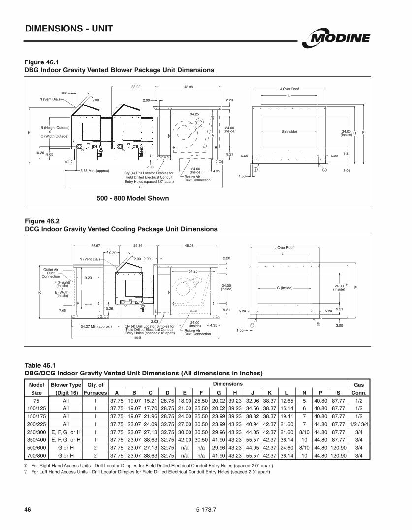
5-173.746
DIMENSIONS - UNIT
Figure 46.1DBG Indoor Gravity Vented Blower Package Unit Dimensions
Table 46.1DBG/DCG Indoor Gravity Vented Unit Dimensions (All dimensions in Inches)
Dimensions
Figure 46.2 DCG Indoor Gravity Vented Cooling Package Unit Dimensions
500 - 800 Model Shown
Qty (4) Drill Locator Dimples for Field Drilled Electrical Conduit Entry Holes (spaced 2.0" apart)
3.86
N (Vent Dia.) 2.00 2.00
33.22 48.08
34.25
A
2.03 24.00(Inside)
24.00(Inside) 24.00
(Inside)
J Over Roof
5.299.21
3.00
G (Inside)
L
H P
9.21
2.20
5.29
1.504.35
Return Air Duct Connection
S
K
10.26 9.05
5.65 Min. (approx)
B (Height Outside) XC (Width Outside)
21Qty (4) Drill Locator Dimples for Field Drilled Electrical Conduit Entry Holes (spaced 2.0" apart)
29.36
2.00 2.00
48.08
2.20
5.299.21
HP
3.00
J Over Roof
G (Inside)
9.21
24.00(Inside)
24.00(Inside)
34.25
36.67
K
Outlet AirDuct
Connection
F (Height)(Inside)
XE (Width)(Inside)
19.23
34.27 Min (approx.)Return Air Duct Connection
7.65 10.26
2.034.35
1.50
5.29
24.00(Inside)
N (Vent Dia.)
12.67
➀
➁
Model Blower Type Qty. of Gas
Size (Digit 16) Furnaces A B C D E F G H J K L N P S Conn.
75 All 1 37.75 19.07 15.21 28.75 18.00 25.50 20.02 39.23 32.06 38.37 12.65 5 40.80 87.77 1/2
100/125 All 1 37.75 19.07 17.70 28.75 21.00 25.50 20.02 39.23 34.56 38.37 15.14 6 40.80 87.77 1/2
150/175 All 1 37.75 19.07 21.96 28.75 24.00 25.50 23.99 39.23 38.82 38.37 19.41 7 40.80 87.77 1/2
200/225 All 1 37.75 23.07 24.09 32.75 27.00 30.50 23.99 43.23 40.94 42.37 21.60 7 44.80 87.77 1/2 / 3/4
250/300 E, F, G, or H 1 37.75 23.07 27.13 32.75 30.00 30.50 29.96 43.23 44.05 42.37 24.60 8/10 44.80 87.77 3/4
350/400 E, F, G, or H 1 37.75 23.07 38.63 32.75 42.00 30.50 41.90 43.23 55.57 42.37 36.14 10 44.80 87.77 3/4
500/600 G or H 2 37.75 23.07 27.13 32.75 n/a n/a 29.96 43.23 44.05 42.37 24.60 8/10 44.80 120.90 3/4
700/800 G or H 2 37.75 23.07 38.63 32.75 n/a n/a 41.90 43.23 55.57 42.37 36.14 10 44.80 120.90 3/4
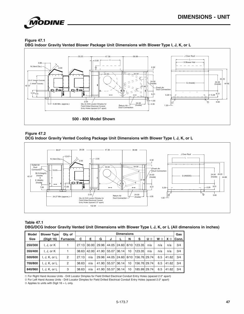
5-173.7
DIMENSIONS - UNIT
47
Dimensions
Figure 47.1 DBG Indoor Gravity Vented Blower Package Unit Dimensions with Blower Type I, J, K, or L
Figure 47.2DCG Indoor Gravity Vented Cooling Package Unit Dimensions with Blower Type I, J, K, or L
Model Blower Type Qty. of Gas
Size (Digit 16) Furnaces C E G J L N S U ➂ W ➂ X ➂ Conn.
250/300 I, J, or K 1 27.13 30.00 29.96 44.05 24.60 8/10 123.35 n/a n/a n/a 3/4
350/400 I, J, or K 1 38.63 42.00 41.90 55.07 36.14 10 123.35 n/a n/a n/a 3/4
500/600
700/800
840/960
Table 47.1DBG/DCG Indoor Gravity Vented Unit Dimensions with Blower Type I, J, K, or L (All dimensions in inches)
G (INSIDE)
J Over Roof
5.29 9.21
3.00
44.80
43.23
7.65
1 2
Field Drilled Electrical Conduit Entry Holes (spaced 2.0" apart)
500 - 800 Model Shown
➀
➁ ➂

48
DIMENSIONS - UNIT
5-173.6
BOTTOM ELECTRICAL CONNECTION KNOCKOUTS, IDENTICAL SIZE AS SIDECONNECTIONS (ONLY ON ACCESS SIDE)
QTY 2 - 1.06 DIA. & QTY 2 - 0.88 DIA. ELECTRICAL CONNECTION KNOCKOUTS (ACCESS SIDE ONLY)
43.2324.00
G
9.21
3.00
5.295.29
1.50
JOVER ROOF30.07
1.982.002.002.00
10.26 (APPROX)
23.07 (HEIGHT) X C (WIDTH) 17.40
1.36
8.97
30.48
5.65 (APPROX)
6" VENTCONNECTOR
24.00
24.00
2.17
9.21
34.00
37.80
4.35
51.20
120.90
Figure 48.1 - DBP Indoor Power Vented Blower Package Unit Dimensions
Model Blower Type Qty. of Gas
Size (Digit 16) Furnaces A B C D E F G H J K L N P S Conn.
75 All 1 37.75 19.07 15.21 28.75 18.00 25.00 20.02 39.23 32.06 38.37 12.65 5 40.80 87.77 1/2
100/125 All 1 37.75 19.07 17.70 28.75 21.00 25.00 20.02 39.23 34.56 38.37 15.14 6 40.80 87.77 1/2
150/175 All 1 37.75 19.07 21.96 28.75 24.00 25.00 23.99 39.23 38.82 38.37 19.41 7 40.80 87.77 1/2
200/225 All 1 37.75 23.07 24.09 32.75 27.00 28.00 23.99 43.23 40.94 42.37 21.60 7 44.80 87.77 1/2 / 3/4
250/300 E, F, G, or H 1 3775 23.07 27.13 32.75 30.00 28.00 29.96 43.23 44.05 42.37 24.60 8/10 44.80 87.77 3/4
350/400 E, F, G, or H 1 37.75 23.07 38.63 32.75 42.00 28.00 41.90 43.23 55.57 42.37 36.14 10 44.80 87.77 3/4
500/600 G or H 2 37.75 23.07 27.13 32.75 n/a n/a 29.96 43.23 44.05 42.37 24.60 8/10 44.80 120.90 3/4
700/800 G or H 2 37.75 23.07 38.63 32.75 n/a n/a 41.90 43.23 55.57 42.37 36.14 10 44.80 120.90 3/4
➀➁
Table 48.1 - DBP/DCP Indoor Power Vented Unit Dimensions (All dimensions in inches)
Dimensions
Figure 48.2 - DCP Indoor Power Vented Cooling Package Unit Dimensions
BOTTOM ELECTRICAL CONNECTION KNOCKOUTS, IDENTICAL SIZE AS SIDECONNECTIONS (ONLY ON ACCESS SIDE)
QTY 2 - 1.06 DIA. & QTY 2 - 0.88 DIA. ELECTRICAL CONNECTION KNOCKOUTS (ACCESS SIDE ONLY)
N
H24.00
G
9.21
3.00
5.295.29
1.50
JOVER ROOF
1.982.002.002.00
P
1.36
30.48 51.20
24.00
24.00
2.17
9.21
34.00
A
4.35
116.98
114.11
32.43
D
19.23
F (HEIGHT)X
E (WIDTH)
7.65
500 - 800 Model Shown

DIMENSIONS - UNIT
495-173.6
Dimensions
BOTTOM ELECTRICAL CONNECTION KNOCKOUTS, IDENTICAL SIZE AS SIDECONNECTIONS (ONLY ON ACCESS SIDE)
QTY 2 - 0.88 DIA. ELECTRICAL CONNECTION KNOCKOUTS (ACCESS SIDE ONLY)
QTY 2 - 1.06 DIA. ELECTRICAL CONNECTION KNOCKOUTS (ACCESS SIDE ONLY)
43.2324.00
G
9.21
3.00
5.295.29
1.50
JOVER ROOF
34.00
36.68
37.85
2.17
24.00
9.21
24.00 4.35
34.00
50.3730.07
156.76
1.982.002.002.00
10.26 (APPROX)
23.07 (HEIGHT) X C (WIDTH) 17.40
1.36
8.97
30.48
147.59
5.65 (APPROX)
6" VENTCONNECTOR
29.74
6.44
41.62
Figure 49.1 - DBP Indoor Power Vented Blower Package Unit Dimensions with Blower Type I, J, K, or L
BOTTOM ELECTRICAL CONNECTION KNOCKOUTS, IDENTICAL SIZE AS SIDECONNECTIONS (ONLY ON ACCESS SIDE)
QTY 2 - 0.88 DIA. ELECTRICAL CONNECTION KNOCKOUTS (ACCESS SIDE ONLY)
QTY 2 - 1.06 DIA. ELECTRICAL CONNECTION KNOCKOUTS (ACCESS SIDE ONLY)
N
43.2324.00
G
9.21
3.00
5.295.29
1.50
JOVER ROOF
34.00
36.68
37.85
2.17
24.00
9.21
24.00 4.35
34.00
50.37
1.982.002.002.00
P
1.36
32.54
D
19.23
30.5 (HEIGHT)X
E (WIDTH)
7.65
30.48
152.83
Figure 49.2 - DCP Indoor Power Vented Cooling Package Unit Dimensions with Blower Type I, J, K, or L
Model Blower Type Qty. of Gas
Size (Digit 16) Furnaces C E G J L N S U ➂ W ➂ X ➂ Conn.
250/300 I, J, or K 1 27.13 30.00 29.96 44.05 24.60 8/10 123.35 n/a n/a n/a 3/4
350/400 I, J, or K 1 38.63 42.00 41.90 55.07 36.14 10 123.35 n/a n/a n/a 3/4
500/600
700/800
840/960
➀➁ ➂
Table 49.1 - DBP/DCP Indoor Power Vented Unit Dimensions with Blower Type I, J, K, or L (All dimensions in inches)
500 - 800 Model Shown
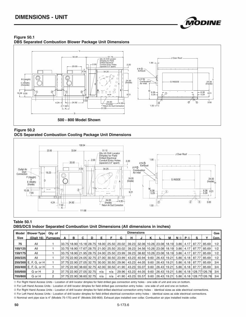
50
DIMENSIONS - UNIT
5-173.6
Figure 50.1DBS Separated Combustion Blower Package Unit Dimensions
Figure 50.2DCS Separated Combustion Cooling Package Unit Dimensions
Table 50.1DBS/DCS Indoor Separated Combustion Unit Dimensions (All dimensions in inches)
Model Blower Type Qty. of Gas
Size (Digit 16) Furnaces A B C D E F G H J K L M N ➄ P ➄ S Y Conn.
75 All 1 33.75 18.90 15.18 28.75 18.00 25.50 20.02 39.23 32.06 10.26 23.08 18.19 3.86 4.17 87.77 85.69 1/2
100/125 All 1 33.75 18.90 17.67 28.75 21.00 25.50 20.02 39.23 34.56 10.26 23.08 18.19 3.86 4.17 87.77 85.69 1/2
150/175 All 1 33.75 18.90 21.95 28.75 24.00 25.50 23.99 39.23 38.82 10.26 23.08 18.19 3.86 4.17 87.77 85.69 1/2
200/225 All 1 37.75 22.90 24.05 32.75 27.00 30.50 23.99 43.23 40.94 9.60 26.43 19.21 5.86 6.18 87.77 85.69 1/2
250/300 E, F, G, or H 1 37.75 22.90 27.05 32.75 30.00 30.50 29.96 43.23 44.05 9.60 26.43 19.21 5.86 6.18 87.77 85.69 3/4
350/400 E, F, G, or H 1 37.75 22.90 38.60 32.75 42.00 30.50 41.90 43.23 55.07 9.60 26.43 19.21 5.86 6.18 87.77 85.69 3/4
500/600 G or H 2 37.75 22.90 27.05 32.75 n/a n/a 29.96 43.23 44.05 9.60 26.43 19.21 5.86 6.18 128.77 126.78 3/4
700/800 G or H 2 37.75 22.90 38.60 32.75 n/a n/a 41.90 43.23 55.57 9.60 26.43 19.21 5.86 6.18 128.77 126.78 3/4
Dimensions
500 - 800 Model Shown
Qty (4) Drill LocatorDimples for Field Drilled Electrical Conduit Entry Holes (spaced 2.0" apart)
51.09
Dimples for Field Drilled Electrical Conduit Entry Holes (spaced 2.0" apart)
➀
➁
➂
➃
➄ Nominal vent pipe size is 4" (Models 75-175) and 6" (Models 200-800). Exhaust pipe installed over collar. Combustion air pipe installed inside collar.

DIMENSIONS - UNIT
515-173.6
Figure 51.1 DBS Separated Combustion Blower Package Unit Dimensions with Blower Type I, J, K, or L
Figure 51.2 DCS Separated Combustion Cooling Package Unit Dimensions with Blower Type I, J, or K
Model Blower Type Qty. of Gas
Size (Digit 16) Furnaces C E G J S U ➅ W ➅ X ➅ Y Conn.
250/300 I, J, or K 1 27.05 30.00 29.96 44.05 123.63 n/a n/a n/a 121.53 3/4
350/400 I, J, or K 1 38.60 42.00 41.90 55.07 123.63 n/a n/a n/a 121.53 3/4
500/600
700/800
840/960
Dimensions
Table 51.1 DBS/DCS Indoor Separated Combustion Unit Dimensions with Blower I, J, K, or L (All dimensions in inches)
500 - 800 Model Shown
21
42
1
3
36.68
10.26
4.24 24.92
5.296.386.38
5.29
1.90
144.84
23.95 33.84 50.37
147.26
37.85
2.03
2.00
4.35(Inside)24.00
34.0034.00
(Inside)24.00
9.21
2.32
Duct Connection Return Air
Duct ConnectionFresh Air
(Inside)E (Width)
X 30.5
7.65
19.23
32.75
Connection Duct Outlet Air
26.4319.21
G INSIDE
J Over Roof
43.23(Inside) 24.00
9.21
3.001.507.30
9.60
20.00
4.50
5.386Exhaust 6.18
CombustionAir Inlet
Ø
Ø
Dimples for Field Drilled Electrical Conduit Entry Holes (spaced 2.0" apart)
Return AirDuct Connection
3
1
2 4
Fresh AirDuct Connection
Ø 5.86Exhaust
5
Ø 6.18CombustionAir Inlet
5
1.90
34.49 50.37 36.68
37.84
2.03
2.00
4.3524.00(Inside)
34.0034.00
24.00(Inside)
9.21
2.32
26.43
19.21
G INSIDE
J Over Roof
43.23
24.00(Inside)
9.21
3.00
1.50
20.00
4.50
7.309.60
24.924.24
5.296.38 6.38
5.29
Y
S
22.90(Height) X
C (Width) (Inside)
9.0510.26
XU
W
1 2 21
74.50
Dimples for Field Drilled Electrical Conduit Entry Holes (spaced 2.0" apart)
➀
➁
➂
➃
➄ Nominal vent pipe size is 4" (Models 75-175) and 6" (Models 200-800). Exhaust pipe installed over collar. Combustion air pipe installed inside collar.➅
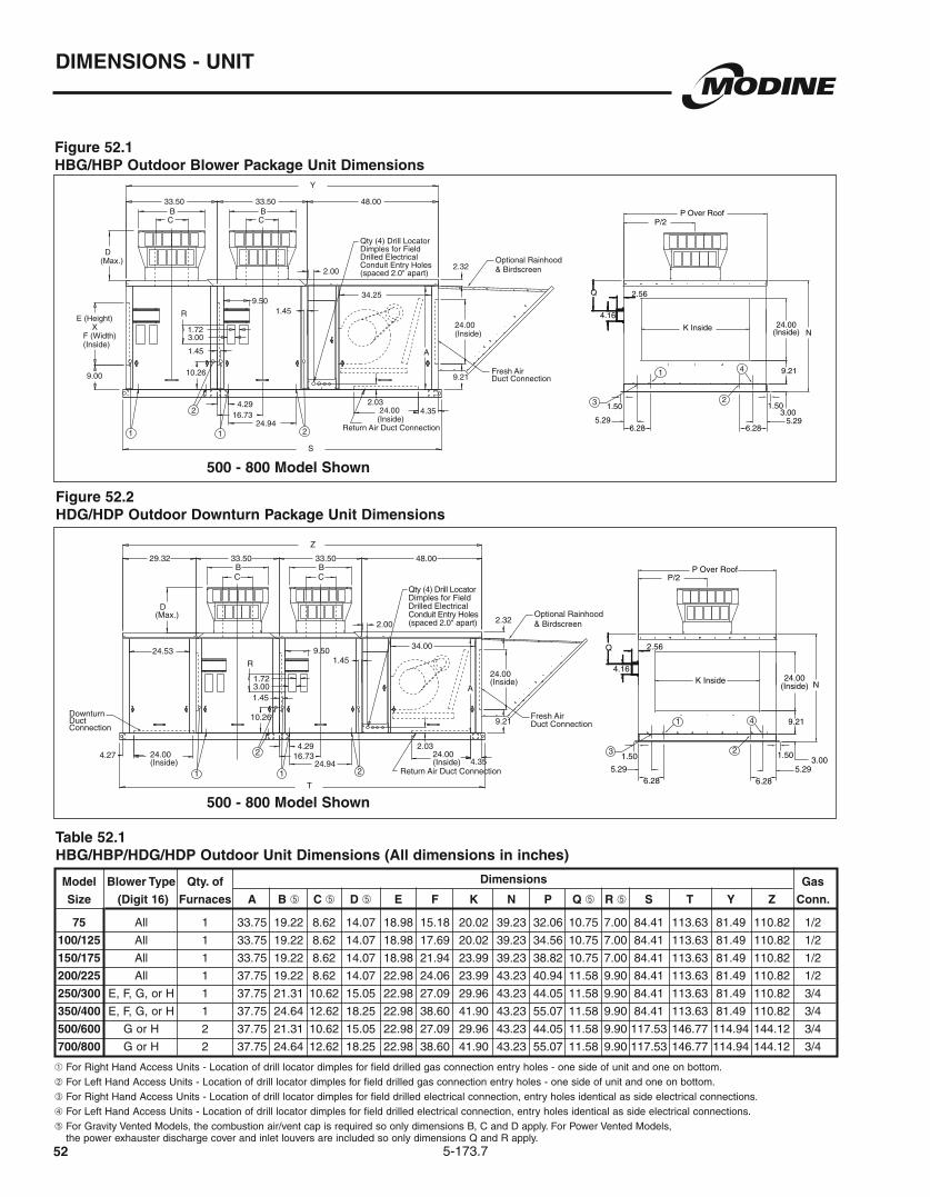
5-173.752
DIMENSIONS - UNIT
Figure 52.1HBG/HBP Outdoor Blower Package Unit Dimensions
Figure 52.2HDG/HDP Outdoor Downturn Package Unit Dimensions
Model Blower Type Qty. of Gas
Size (Digit 16) Furnaces A B ➄ C ➄ D ➄ E F K N P Q ➄ R ➄ S T Y Z Conn.
75 All 1 33.75 19.22 8.62 14.07 18.98 15.18 20.02 39.23 32.06 10.75 7.00 84.41 113.63 81.49 110.82 1/2
100/125 All 1 33.75 19.22 8.62 14.07 18.98 17.69 20.02 39.23 34.56 10.75 7.00 84.41 113.63 81.49 110.82 1/2
150/175 All 1 33.75 19.22 8.62 14.07 18.98 21.94 23.99 39.23 38.82 10.75 7.00 84.41 113.63 81.49 110.82 1/2
200/225 All 1 37.75 19.22 8.62 14.07 22.98 24.06 23.99 43.23 40.94 11.58 9.90 84.41 113.63 81.49 110.82 1/2
250/300 E, F, G, or H 1 37.75 21.31 10.62 15.05 22.98 27.09 29.96 43.23 44.05 11.58 9.90 84.41 113.63 81.49 110.82 3/4
350/400 E, F, G, or H 1 37.75 24.64 12.62 18.25 22.98 38.60 41.90 43.23 55.07 11.58 9.90 84.41 113.63 81.49 110.82 3/4
500/600 G or H 2 37.75 21.31 10.62 15.05 22.98 27.09 29.96 43.23 44.05 11.58 9.90 117.53 146.77 114.94 144.12 3/4
700/800 G or H 2 37.75 24.64 12.62 18.25 22.98 38.60 41.90 43.23 55.07 11.58 9.90 117.53 146.77 114.94 144.12 3/4
Table 52.1HBG/HBP/HDG/HDP Outdoor Unit Dimensions (All dimensions in inches)
Dimensions
➀
➁
➂
➃
➄ For Gravity Vented Models, the combustion air/vent cap is required so only dimensions B, C and D apply. For Power Vented Models, the power exhauster discharge cover and inlet louvers are included so only dimensions Q and R apply.
5.295.29
K Inside
P Over RoofP/2
N
9.21
3.00
24.00(Inside)
1.501.50
6.28 6.28
Q
4.16
2.56
1 1
2
2
Optional Rainhood& Birdscreen
Fresh AirDuct Connection
Return Air Duct Connection
9.00
E (Height) X F (Width) (Inside)
48.0033.50
10.26
R
1.723.00
1.45
9.50
CB
1.45
24.94
4.29
D(Max.)
2.03
Dimples for Field Drilled Electrical Conduit Entry Holes (spaced 2.0" apart)
16.73
B
34.25
C
2.00 2.32
9.21
24.00(Inside)
33.50
24.00(Inside)
A
4.35
S
Y
1
23
4
500 - 800 Model Shown
500 - 800 Model Shown
5.29 5.29
K Inside
P Over Roof P/2
N
9.21
3.00
24.00 (Inside)
1.50 1.50
6.28 6.28
4.16
2.56 Q
Fresh Air Duct Connection
Optional Rainhood & Birdscreen
Downturn Duct Connection
2 1
2
1 Return Air Duct Connection
48.00
24.00 (Inside)
9.21
2.32 2.00
C
24.00 (Inside)
34.00
A
B
16.73 2.03
D (Max.)
24.00 (Inside)
4.27 4.29
24.94
1.45
B C
29.32
9.50
1.45 3.00 1.72
R
10.26
33.50 33.50
24.53
4.35
T
Z
1
2
4
3
Dimples for Field Drilled Electrical Conduit Entry Holes (spaced 2.0" apart)

5-173.7 53
DIMENSIONS - UNIT
Figure 53.1 HBG/HBP Outdoor Blower Package Unit Dimensions with Blower Type I, J, K, or L
Figure 53.2 HDG/HDP Outdoor Downturn Package Unit Dimensions with Blower Type I, J, K, or L
Model Blower Type Qty. of Gas
Size (Digit 16) Furnaces B ➄ C ➄ D ➄ E F K P Q ➄ R ➄ S T Y Z Conn.
250/300 I, J, or K 1 21.31 10.62 15.05 33.50 27.09 29.96 44.05 11.58 9.90 120.00 149.22 117.34 146.66 3/4
350/400 I, J, or K 1 24.64 12.62 18.25 33.50 38.60 41.90 55.57 11.58 9.90 120.00 149.22 117.34 146.66 3/4
500/600
700/800
840/960
Table 53.1 HBG/HBP/HDG/HDP Outdoor Unit Dimensions with Blower I, J, K, or L (All dimensions in inches)
Dimensions
➀
➁
➂
➃
➄ For Gravity Vented Models, the combustion air/vent cap is required so only dimensions B, C and D apply. For Power Vented Models, the power exhauster discharge cover and inlet louvers are included so only dimensions Q and R apply.
➅
500 - 800 Model Shown
500 - 800 Model Shown
Fresh AirDuct Connection
Optional Rainhood& Birdscreen
Return AirDuct Connection2
2
11
3
1
2
4
E
41.62
6.56
29.74
Y
K Inside2.56
4.16
Q
P Over Roof
P/2
43.23
24.00(Inside)
9.21
3.001.505.296.28
1.505.296.28
24.00(Inside)
9.21
2.32
2.00
C
36.58
4.3524.00(Inside)
34.0034.00
37.85
BCB
16.732.03
D(Max.)
4.29
24.94
1.459.50
1.45
3.001.72
R
10.26
47.27
S
22.98 (Height)X
F(Width)(Inside)
9.00
Qty (4) Drill LocatorDimples for Field Drilled Electrical Conduit Entry Holes (spaced 2.0" apart)
➅
2
1
3
Fresh AirDuct Connection
Optional Rainhood& Birdscreen
Return AirDuct Connection
DownturnDuctConnection
21
2
1
4
E
29.74
6.56
41.62
K Inside2.56
4.16
Q
P Over Roof
P/2
43.23
24.00(Inside)
9.21
3.001.505.296.28
1.505.296.28
24.00(Inside)
9.21
2.32
2.00
C
36.58
4.3524.00(Inside)
34.0034.00
37.85
BCB
16.732.03
D(Max.)
24.00(Inside)4.27
4.29
24.94
1.45
T
29.32
9.50
1.45
3.001.72R
10.26
47.27
Z
24.53
Qty (4) Drill LocatorDimples for Field Drilled Electrical Conduit Entry Holes (spaced 2.0" apart)
➅

5-173.754
DIMENSIONS - UNIT
Figure 54.1HCG/HCP Outdoor Cooling Package Unit Dimensions
Figure 54.2HPG/HPP Outdoor Packaged Unit Dimensions
Model Blower Type Gas
Size (Digit 16) A B ➄ C ➄ D ➄ G H J K N P Q ➄ R ➄ Conn.
75 All 33.75 19.22 8.62 14.07 28.75 18.00 25.50 20.02 39.23 32.06 10.75 7.00 1/2
100/125 All 33.75 19.22 8.62 14.07 28.75 21.00 25.50 20.02 39.23 34.56 10.75 7.00 1/2
150/175 All 33.75 19.22 8.62 14.07 28.75 24.00 25.50 23.99 39.23 38.82 10.75 7.00 1/2
200/225 All 37.75 19.22 8.62 14.07 32.75 27.00 30.50 23.99 43.23 40.94 11.58 9.90 1/2
250/300 E, F, G, or H 37.75 21.31 10.62 15.05 32.75 30.00 30.50 29.96 43.23 44.05 11.58 9.90 3/4
350/400 E, F, G, or H 37.75 24.64 12.62 18.25 32.75 42.00 30.50 41.90 43.23 55.57 11.58 9.90 3/4
Dimensions
Table 54.1HCG/HCP/HPG/HPP Outdoor Unit Dimensions (All dimensions in inches)
Outlet AirDuct
Connection
Return Air Duct Connection
Fresh Air Duct Connection
Optional Rainhood& Birdscreen
1.45
24.944.29
34.25
108.39
48.00105.49
2.00
J (Height) X
H (Width)(Inside)
7.65
19.23
G
1.45
10.26
16.75
24.00 33.50
D (Max.)
CB
2.03
4.3524.00
(Inside)
A
2.20
24.00(Inside)
9.21
5.295.29
K Inside
P Over RoofP/2
N
9.21
3.00
24.00(Inside)
1.501.50
6.28 6.28
Q
4.16
2.569.50
R
3.001.72
Dimples for Field Drilled Electrical Conduit Entry Holes (spaced 2.0" apart)
Downturn Duct
Connection
Return Air Duct Connection
Fresh Air Duct Connection
Optional Rainhood& Birdscreen
1.45
24.944.29
137.63
34.25
48.00
134.82
24.53
24.00(Inside)4.27
29.32 24.00
G
19.23
1.45
10.26
16.75
2.03
2.00
24.00(Inside) 4.35
A
24.00(Inside)
9.21
2.20
D (Max.)
CB
33.50
5.295.29
K Inside
P Over RoofP/2
N
9.21
3.00
24.00(Inside)
1.501.50
6.28 6.28
9.50
R
3.001.72
4.16
2.56Q
Dimples for Field Drilled Electrical Conduit Entry Holes (spaced 2.0" apart)
➀
➁
➂
➃
➄ For Gravity Vented Models, the combustion air/vent cap is required so only dimensions B, C and D apply. For Power Vented Models, the power exhauster discharge cover and inlet louvers are included so only dimensions Q and R apply.

5-173.7 55
DIMENSIONS - UNIT
Figure 55.1 HCG/HCP Outdoor Cooling Package Unit Dimensions with Blower Type I, J, or K
Figure 55.2 HPG/HPP Outdoor Packaged Unit Dimensions with Blower Type I, J or K
Model Blower Type Gas
Size (Digit 16) B ➄ C ➄ D ➄ F H K N P Q ➄ R ➄ Conn.
250/300 I, J, or K 21.31 10.62 15.05 27.09 30.00 29.96 43.23 44.05 11.58 9.90 3/4
350/400 I, J, or K 24.64 12.62 18.25 38.60 42.00 41.90 43.23 55.07 11.58 9.90 3/4
Dimensions
Table 55.1 HCG/HCP/HPG/HPP Outdoor Unit Dimensions (All dimensions in inches)
Outlet AirDuct Connection
Return Air Duct Connection
Fresh Air Duct Connection
Optional Rainhood& Birdscreen
1.45
24.944.29143.98
24.00
141.34
D (Max.)
28.00 (Height) XH (Width)
(Inside)
7.65
32.68
19.23
10.26
37.85
B
1.45
16.73
2.03
2.00
C
33.50 47.27 36.58
4.3524.00(Inside)
34.0034.00
24.00(Inside)
9.21
2.32
5.295.29
K Inside
P Over RoofP/2
N
9.21
3.00
24.00(Inside)
1.501.50
6.28 6.28
9.50
R
3.001.72
Q
4.16
2.56
Dimples for Field Drilled Electrical Conduit Entry Holes (spaced 2.0" apart)
Downturn Duct
Connection
Return Air Duct Connection
Optional Rainhood& Birdscreen
Fresh Air Duct Connection
1.45
24.944.29
4.27 24.00(Inside)
24.53
29.32
173.22
170.66
2.03
16.73
1.45
B
37.85
10.26
19.23
32.68
D (Max.)
24.00
34.00 34.00
24.00(Inside)
4.35
36.5847.2733.50
C
2.00 2.32
9.21
24.00(Inside)
5.295.29
K Inside
P Over RoofP/2
N
9.21
3.00
24.00(Inside)
1.501.50
6.28 6.28
9.50
R3.00
1.72
4.16
2.56Q
Dimples for Field Drilled Electrical Conduit Entry Holes (spaced 2.0" apart)
➀
➁
➂
➃
➄ For Gravity Vented Models, the combustion air/vent cap is required so only dimensions B, C and D apply. For Power Vented Models, the power exhauster discharge cover and inlet louvers are included so only dimensions Q and R apply.

5-173.756
DIMENSIONS - INDOOR UNIT BASE
Dimensions Model Blower Type DBG DBS DBG & DBS
Size (Digit 16) A C D N K L A C D N K L B E J M
75 All 87.77 81.30 87.77 84.73 34.85 19.52 32.00 6.23
100/125 All 87.77 81.30 87.77 84.73 37.36 19.52 34.50 7.49
150/175 All 87.77 81.30 87.77 84.73 41.61 23.49 38.75 7.63
200/225 All 87.77 81.30 87.77 84.73 43.71 23.49 40.85 8.69
250/300 E,F,G, or H 87.77 81.30 87.77 84.73 46.75 29.46 43.89 7.21
250/300 I, J, or K 123.35 117.26 123.62 120.57 46.75 29.46 43.89 7.21
350/400 E,F,G, or H 87.77 81.30 87.77 84.73 58.27 41.40 55.41 7.00
350/400 I, J, or K 123.35 117.26 123.62 120.57 58.27 41.40 55.41 7.00
500/600 G, or H 120.90 111.68 34.12 89.14 34.12 128.77 119.54 42.00 97.03 42.00 46.75 29.46 43.89 7.21
500/600 164.63 155.41 42.00 125.70 91.15 46.75 29.46 43.89 7.21
700/800 G, or H 120.90 111.68 34.12 89.14 34.12 128.77 119.54 42.00 97.03 42.00 58.27 41.40 55.41 7.00
700/800 164.63 155.41 42.00 125.70 90.15 58.27 41.40 55.41 7.00
840/960
Figure 56.1Unit Base Dimensions
Table 56.1Indoor Blower Package Unit Base Rail Dimensions (all dimensions in inches)
Table 56.2Indoor Cooling Package Unit Base Rail Dimensions (all dimensions in inches)
Dimensions Model Blower Type DCG DCS DCG & DCS
Size (Digit 16) A C A C B E F G J M
75 All 116.98 114.07 111.75 108.75 34.85 19.52 81.88 56.96 32.00 6.23
100/125 All 116.98 114.07 111.75 108.75 37.36 19.52 81.88 56.96 34.50 7.49
150/175 All 116.98 114.07 111.75 108.75 41.61 23.49 81.88 56.96 38.75 7.63
200/225 All 116.98 114.07 111.75 108.75 43.71 23.49 81.88 56.96 40.85 8.69
250/300 E, F, G, or H 116.98 114.07 111.75 108.75 46.75 29.46 81.88 56.96 43.89 7.21
250/300 I, J, or K 152.84 149.93 147.60 144.60 46.75 29.46 117.73 92.81 43.89 7.21
350/400 E, F, G, or H 116.98 114.07 111.75 108.75 58.27 41.40 81.88 56.96 55.41 7.00
350/400 I, J, or K 152.84 149.93 147.60 144.60 58.27 41.40 117.73 92.81 55.41 7.00
0.75" Suspension
Hanging Locations(Typical 4 Corners)
0.63
2.36
1.45
Return Air Opening
4.35
24.00Inside
M
E Inside
M
C To end of unitA
J
B
D
KL
N
LiftingPoint
SuspensionPoint
SuspensionPoint Lifting
Point

5-173.7 57
DIMENSIONS - OUTDOOR UNIT BASE
Return Air OpeningSupply Air Opening
6.28
6.28
To end of UnitA
C
F
G
H
M
E
M
M
E
M
Inside 4.3524.00Inside24.004.29
JB
InsideInside
Drill Locator Dimples for Field Drilled Gas Connection Entry HolesLeft Hand Access Units
Drill Locator Dimples for Field Drilled Gas Connection Entry HolesRight Hand Access Units
Figure 57.1 - Unit Base Dimensions
Table 57.1 - HBG/HBP & HDG/HDP Outdoor Unit Base Rail Dimensions (All dimensions in inches)
Dimensions Model Blower Type HBG/HBP HDG/HDP HBG/HBP/HDG/HDP
Size (Digit 16) A C A C B E F ➀ G ➀ H J M
75 All 84.41 81.49 113.63 110.82 34.85 19.52 78.66 53.72 1.53 32.00 6.23
100/125 All 84.41 81.49 113.63 110.82 37.36 19.52 78.66 53.72 1.53 34.50 7.49
150/175 All 84.41 81.49 113.63 110.82 41.61 23.49 78.66 53.72 1.53 38.75 7.63
200/225 All 84.41 81.49 113.63 110.82 43.71 23.49 78.66 53.72 1.53 40.85 8.69
250/300 E,F,G, or H 84.41 81.49 113.63 110.82 46.75 29.46 78.66 53.72 1.53 43.89 7.21
250/300 I, J, or K 120.00 117.34 149.22 146.66 46.75 29.46 114.23 84.29 1.28 43.89 7.21
350/400 E,F,G, or H 84.41 81.49 113.63 110.82 58.27 41.40 78.66 53.72 1.53 55.41 7.00
350/400 I, J, or K 120.00 117.34 149.22 146.66 58.27 41.40 114.23 82.29 1.28 55.41 7.00
500/600 G or H 117.53 114.94 146.77 144.12 46.75 29.46 78.66 53.72 1.53 43.89 7.21
500/600
700/800 G or H 117.53 114.94 146.77 144.12 58.27 41.40 78.66 53.72 1.53 55.41 7.00
700/800
840/960
Table 57.2 - HCG/HCP & HPG/HPP Outdoor Unit Base Rail Dimensions (All dimensions in inches)
Dimensions Model Blower Type HCG/HCP HPG/HPP HCG/HCP/HPG/HPP
Size (Digit 16) A C A C B E F G H J M
75 All 108.39 105.49 137.63 134.82 34.85 19.52 78.66 53.72 1.53 32.00 6.23
100/125 All 108.39 105.49 137.63 134.82 37.36 19.52 78.66 53.72 1.53 34.50 7.49
150/175 All 108.39 105.49 137.63 134.82 41.61 23.49 78.66 53.72 1.53 38.75 7.63
200/225 All 108.39 105.49 137.63 134.82 43.71 23.49 78.66 53.72 1.53 40.85 8.69
250/300 E,F,G, or H 108.39 105.49 137.63 134.82 46.75 29.46 78.66 53.72 1.53 43.89 7.21
250/300 I, J, or K 143.98 141.34 173.22 170.66 46.75 29.46 114.23 82.29 1.28 43.89 7.21
350/400 E,F,G, or H 108.39 105.49 137.63 134.82 58.27 41.40 78.66 53.72 1.53 55.41 7.00
350/400 I, J, or K 143.98 141.34 173.22 170.66 58.27 41.40 114.23 82.29 1.28 55.41 7.00
➀ Gas connection for first furnace. For Models 500-800 add 33.5” for second furnace gas connection. For Model 840-960 add 33.50” and 67.00” for second and third furnace gas connections.

5-173.758
DIMENSIONS - ROOF CURBS
F EINSIDE
OUTSIDE44.16
C
D
B
A
INSIDE
OUTSIDE
3 SPACES AT
2.00 = 6.00 (TYP)
G
2.97 TYP
HINSIDE RETURN
AIR OPENING
5.53
5.53Y)
. BOTT PAN CONN.
Y)
24.00 INSIDEOPENING
24.94
24.00 INSIDEOPENING
J
1.79
1.681.75TYP
HINSIDE DISCHARGE
AIR OPENING
1.00TYP
16.00
G
Figure 58.1 - Roof Curb Dimensions
Table 58.1 - HBG/HBP & HDG/HDP Roof Curb Dimensions (All dimensions in inches)
Table 58.2 - HCG/HCP & HPG/HPP Roof Curb Dimensions (All dimensions in inches)
Dimensions Model Blower Type HCG/HCP HPG/HPP HCG/HCP/HPG/HPP
Size (Digit 16) A B C D A B C D E F G H J
75 All 112.74 100.74 - - 141.98 129.98 100.74 29.24 39.33 27.33 3.97 19.52 74.84
100/125 All 112.74 100.74 - - 141.98 129.98 100.74 29.24 41.84 29.84 5.22 19.52 74.84
150/175 All 112.74 100.74 - - 141.98 129.98 100.74 29.24 46.18 34.18 5.41 23.49 74.84
200/225 All 112.74 100.74 - - 141.98 129.98 100.74 29.24 48.22 36.22 6.43 23.49 74.84
250/300 E,F,G, or H 112.74 100.74 - - 141.98 129.98 100.74 29.24 51.25 39.25 4.96 29.46 74.84
250/300 I, J, or K 148.59 136.59 105.98 30.61 177.83 165.83 105.98 59.85 51.25 39.25 4.96 29.46 110.41
350/400 E,F,G, or H 112.74 100.74 - - 141.98 129.98 100.74 29.24 62.76 50.76 4.74 41.40 74.84
350/400 I, J, or K 148.59 136.59 105.98 30.61 177.83 165.83 105.98 59.85 62.76 50.76 4.74 41.40 110.41
Dimensions Model Blower Type HBG/HBP HDG/HDP HBG/HBP/HDG/HDP
Size (Digit 16) A B C D A B C D E F G H J ➀
75 All 88.77 76.77 - - 117.98 105.98 - - 39.33 27.33 3.97 19.52 74.84
100/125 All 88.77 76.77 - - 117.98 105.98 - - 41.84 29.84 5.22 19.52 74.84
150/175 All 88.77 76.77 - - 117.98 105.98 - - 46.18 34.18 5.41 23.49 74.84
200/225 All 88.77 76.77 - - 117.98 105.98 - - 48.22 36.22 6.43 23.49 74.84
250/300 E,F,G, or H 88.77 76.77 - - 117.98 105.98 - - 51.25 39.25 4.96 29.46 74.84
250/300 I, J, or K 124.61 112.61 - - 153.83 141.63 105.98 35.85 51.25 39.25 4.96 29.46 110.41
350/400 E,F,G, or H 88.77 76.77 - - 117.98 105.98 - - 62.76 50.76 4.74 41.40 74.84
350/400 I, J, or K 124.61 112.61 - - 153.83 141.63 105.98 35.85 62.76 50.76 4.74 41.40 110.41
500/600 G or H 121.89 109.89 - - 151.10 139.10 105.98 33.12 51.25 39.25 4.96 29.46 74.84
500/600
700/800 G or H 121.89 109.89 - - 151.10 139.10 105.98 33.12 62.76 50.76 4.74 41.40 74.84
700/800
840/960
➀ Gas connection for first furnace. For Models 500-800 add 33.5” for second furnace gas connection. For Model 840-960 add 33.50” and 67.00” for second and third furnace gas connections.
Discharge Air Openingis for HDG/HDP/HPG/HPPmodels only

5-173.7 59
DIMENSIONS - RAINHOOD AND BIRDSCREEN & REMOTE PANEL
C
3.38
2.13
3.53
B
3.53A
5.57
2.56
1.50
NOTES:1. Holes visible on right side are also on left side in the same location.2. Holes on top are also on the back in the same location horizontally, 1" down vertically.
Remote Panel Type A B C
10.60 3.53 4.58
Two Stage Thermostat 13.09 6.03 5.82
Custom Remote Monitoring PanelsCustom remote monitoring panels are available with any combination of light, switch, and/or thermostat panels. Specify the number of lights, switches, and/or thermostat as desired. All lights and switches must be tagged only with the listed tags.
Figure 59.2Remote Panel Dimensions (All dimensions in inches)
Thermostat Panel Style
❏ None
❏ Single Stage
❏ Two Stage
❏
Available Light Tags
Heat On Evap On
Blower On Smoke Alarm
Blower On (High) Power On
Dirty Filters
Cool On
Available Switch Tags
2 Position Tags 3 Position Tags
Day/Night Heat/Vent/Cool
Occupied/Unoccupied Summer/Off/Winter
On/Off Heat/Off/Vent
Heat/Off On//Off/ Auto
Summer/Winter
Heat/Cool
Auto/Off
32.71
1.09
31.19
.75
1.14A1.14
44.56
42.66 Approx.
Figure 59.1Rainhood and Birdscreen Dimensions (Outdoor Only)(All dimensions in inches)
Model Size 75 100/125 150/175 200/225 250/300 350/400 500/600 700/800 840/960A 29.43 31.94 38.24 38.24 41.34 52.85 41.34 52.85 52.85

5-173.760
WEIGHTS
Type of Unit
Model Size
Blower Type
(Digit 16)
Blower Only Blower + CoolingBlower + Downturn
Blower + Cooling + Downturn
DBG DBP DBSHBG
(w/cap)HBP DCG DCP DCS
HCG (w/cap)
HCPHDG
(w/cap)HDP
HPG (w/cap)
HPP
75 All 236 248 373 445 439 343 355 480 552 546 546 540 653 647
100/125 All 272 284 409 480 474 382 394 519 590 584 584 578 694 688
150/175 All 308 320 441 517 511 423 435 556 632 626 627 621 742 736
200/225 All 365 377 515 589 588 491 503 641 715 714 708 707 834 833
250/300 E,F,G, or H 396 408 568 637 626 526 538 698 767 756 758 747 888 877
250/300 I, J, or k 645 657 817 886 875 775 787 947 1016 1005 1007 996 1137 1126
350/400 E,F,G, or H 482 494 652 758 738 631 643 801 907 887 896 876 1045 1025
350/400 I, J, or k 763 775 933 957 1019 912 924 1082 1106 1168 1095 1157 1244 1306
500/600 G or H 577 589 843 981 959 n/a n/a n/a n/a n/a 1102 1080 n/a n/a
500/600 826 838 1092 1230 1208 n/a n/a n/a n/a n/a 1351 1329 n/a n/a
700/800 G or H 733 745 981 1193 1153 n/a n/a n/a n/a n/a 1331 1291 n/a n/a
700/800 1014 1026 1262 1392 1352 n/a n/a n/a n/a n/a 1530 1490 n/a n/a
840/960 1265 1277 1591 1827 1767 n/a n/a n/a n/a n/a 1965 1905 n/a n/a
Table 60.1 - Base Unit Weights
Table 60.2 - Option Weights
Dampers Insulation Double Wall RainhoodEvap
Cooler
Model Size
Blower Type(Digit 16) Motor Filters
Fresh Air
Fresh & Return
AirDBG, DBP,
DBSDCG, DCP,
DCS
DBG, DBP, DBS, HBG,
HBP
DCG, DCP, DCS, HCG,
HCP HDG, HDP HPG, HPP“H”
Series“H”
Series75 All
See
Mot
or D
ata
6 26 46 5 10 38 72 73 107 65
See
Eva
p C
oole
r D
ata
100/125 All 6 26 46 5 10 38 72 73 107 67
150/175 All 6 29 52 5 10 43 77 78 112 70
200/225 All 6 29 52 7 12 46 85 86 125 72
250/300 E,F,G, or H 8 33 60 7 12 46 87 88 129 83
250/300 I, J, or k 15 33 60 14 19 93 134 135 176 83
350/400 E,F,G, or H 12 38 70 7 12 53 101 102 150 90
350/400 I, J, or k 17 38 70 14 19 96 144 145 193 90
500/600 G or H 8 33 60 7 n/a 46 n/a 88 n/a 83
500/600 15 33 60 14 n/a 93 n/a 135 n/a 83
700/800 G or H 12 38 70 7 n/a 53 n/a 102 n/a 90
700/800 17 38 70 14 n/a 96 n/a 145 n/a 90
840/960 17 38 70 14 n/a 96 n/a 145 n/a 90

5-173.7 61
THIS PAGE INTENTIONALLY LEFT BLANK

5-173.762
COOLING CABINET SPECIFICATIONS
Cooling Section Specifications for sizes 75-400Models with a cooling section can be provided with either a factory installed direct expansion (DX) evaporator, a chilled fluid (for use with water, ethylene glycol, or propylene glycol fluids) coil, or the coil can be field supplied and installed by others. The cooling section is located downstream of the duct furnace heat exchanger in a blow-through configuration, preventing condensation on the heat exchanger in the cooling mode. Thus, a stainless steel heat exchanger is not required when a cooling section is used. (However, a stainless steel heat exchanger is still recommended when the combined entering/return air to the unit is below 40°F.)
The cooling section includes a full coverage, 3-way sloping 409 stainless steel drain pan to remove condensate from coil headers, thermal expansion valves, and refrigerant piping. Insulation is standard on outdoor units and optional on indoor units and double wall construction is optional on all units. The cabinet includes two doors, a removable upper door for service access to the coil once the plumbing has been installed and a lower door which includes a factory supplied 1" stubbed drain connection to the exterior of the cabinet. Field connections for coil inlet and outlet piping can be made through the cabinet corner post or back of the unit. The cooling section duct transition includes 1-1/2" flanges for fastening the sides of the coil. The bottom duct transition is angled to remove any condensation that may be entrained in the supply air stream.
For field supplied coils, do not exceed the factory installed coil dimensions. When obtaining the specifications from a coil manufacturer, it is important to obtain the pressure drop through the coil so that the proper motor horsepower can be selected.
DX - Single Circuit DX - Dual Circuit Chilled Water Max. Cooling Tons ② ③
Max Coil Area Max Coil Area Max Coil Area DX Chilled CFM ➀ (Sq. Ft.) CFM ➀ (Sq. Ft) CFM ➀ (Sq. Ft.) Coils Water Coils
75 1891 3.44 1707 3.10 1676 3.05 609 ④ 9.38 10.56
100 2206 4.01 2048 3.72 2011 3.66 741 ⑤ 11.43 12.62
125 2206 4.01 2048 3.72 2011 3.66 926 11.43 12.62
150 2521 4.58 2416 4.39 2372 4.31 1111 13.42 14.77
175 2521 4.58 2416 4.39 2372 4.31 1296 13.42 14.77
200 3352 6.09 3165 5.76 3214 5.84 1481 18.12 19.28
225 3352 6.09 3165 5.76 3214 5.84 1667 18.12 19.28
250 3724 6.77 3538 6.43 3592 6.53 1852 20.24 21.33
300 3724 6.77 3538 6.43 3592 6.53 2222 20.24 21.33
350 5214 9.48 4996 9.08 5073 9.22 2593 27.26 29.25
400 5214 9.48 4996 9.08 5073 9.22 2963 27.26 29.25
➀ Based on 550 feet per minute (FPM) coil face velocity.➁ 1 Ton = 12,000 Btu/Hr➂ Based on 95°F Entering Dry Bulb, 75° Entering Wet Bulb - Refer to page 65 for refrigerant conditions and page 67 for chilled water conditions.➃ Model Size 75 CFM listed for Chilled Water - DX Single Circuit CFM minimum is 688 and DX Dual Circuit CFM min is 621.➄ Model Size 100 CFM listed for Chilled Water - DX Single Circuit CFM minimum is 802 and DX Dual Circuit CFM min is 745.
Model Size
Figure 62.1 Cooling Section
Table 62.1 Cooling Coil Performance Limits
Min CFM
(All Units)
Optional double wall construction
DX single circuit (shown) and dual circuit coils available
Optional Factory InstalledDX or Chilled Water coil.
Fin spacings of 6,8,10,12or 14 fins per inch
mounting bracket for 2,3,4 and 6 row coils
Full coverage 3-way sloping 409 stainless steel drain pan
1” stubbed drain connection
Right or left hand coil header access to match gas controls

5-173.7
COOLING COIL SELECTION
Cooling Coil SelectionModine BreezeTM AccuSpec selection software is the preferred method of cooling coil sizing and selection because of the variety of inlet air conditions and unit airflow. The following tables provide general performance of the cooling coil options available.
Unit Selection InformationCooling coil selection requires the following inputs:
Cooling Coil Selection Inputs (All Coils) Model Size to determine cabinet dimensions. Airflow in Actual Cubic Feet Per Minute (ACFM) and
Altitude. Note: For manual selection in performance tables, the ACFM needs to be converted to Standard Cubic Feet Per Minute (SCFM). Entering Air Conditions (Dry and Wet Bulb) to the coil.
Units with both outside and return air require the mixed air temperature to be calculated - See below for Mixed
Air Temperature Calculation. Refer to the ASHRAE Fundamentals Handbook for Cooling Climatic Design Information for outside air data.
Cooling capacity required in MBH or Tons.DX Cooling Additional Inputs Refrigerant is R410A. Consult factory for other refrigerants. Evaporator circuiting - Single Circuit (1-Stage Cooling) or
Dual Circuit (2-Stage Cooling) Suction Temperature (°F) (°F) Refrigerant Super Heat Temperature (°F)
Chilled Water Additional Inputs Fluid Type: Water, Ethylene Glycol, or Propylene Glycol. Mixture Percent: For Glycol solutions, the percentage of
the solution that is either ethylene or propylene (0-60%). Entering Fluid Temperature (°F) Fluid Flow Rate
MIXED AIR TEMPERATURE CALCULATIONThe cooling coil capacity is based on the mixed air temperature seen by the cooling coil. When outside air and return air streams are mixed and then delivered to the cooling coil, the mixed air temperature must be calculated to determine the capacity.
Mixed Air Dry Bulb Formula Outside Air DB x Percent Outside Air+ Return Air DB x Percent Return Air Mixed Air Dry Bulb
Mixed Air Dry Bulb Formula Outside Air Enthalpy x Percent Outside Air+ Return Air Enthalpy x Percent Return Air Mixed Air Enthalpy
The Outside and Return Air Enthalpy is determined from Table 63.1 and the Mixed Air Enthalpy is converted back to a Mixed Air Web Bulb using the same table.
Table 63.1Enthalpy of Saturated Air for Various Wet Bulb Temp.
Example:A heating & make-up air unit in Chicago is operating at 5000 CFM and is designed to deliver a maximum of 30% outside air. The outside design air conditions are 88°F DB / 73°F WB and the return air conditions are 75°F DB / 63°F WB.The mixed dry bulb is calculation is
88°F DB x .30 = 26.4°F + 75°F DB x .70 = + 52.5°F Mixed Air Dry Bulb 78.9°F
To determine the mixed wet bulb the enthalpies must be determined. Using Table 63.1, 73°F = 36.75 Btu/lb and 63°F = 28.58 Btu/lb. Thus
36.75°F Btu/lb x .30 = 11.03 + 28.58°F Btu/lb x .70 = + 20.01 Mixed Air Enthalpy 31.04 Btu/lb
Using the Table 63.1, 31.04 Btu/lb = 66.3°F
STANDARD (SCFM) AIRFLOW CALCULATIONFor elevations above 1500 feet, the selection of a cooling coil using a catalog method requires the conversion of the airflow from actual CFM (ACFM) to standard CFM (SCFM). The Modine BreezeTM AccuSpec selection software is the preferred method of cooling coil sizing and selection because the airflow correction is automatically calculated. Blower motor Hp must be selected using ACFM as blowers are constant volume devices. Cooling coil performance tables are based on SCFM (standard air density) and therefore the air volume must be converted to ACFM to determine the performance. The formula for conversion is:
SCFM = ACFM x Air Density Correction Factor
where the Air Density factor can be found in Table 63.2 for various temperatures and elevations. The air temperature used would be the Mixed Air Dry Bulb temperature.
Table 63.2Air Density Correction Factor
63
Air Temp Altitude (Feet)
(°F) 0 1500 2000 3000 4000 5000 6000
60 0.98 1.02 1.06 1.09 1.14 1.18 1.22
70 1.00 1.06 1.08 1.12 1.26 1.20 1.25
80 1.02 1.08 1.10 1.14 1.18 1.22 1.27
90 1.04 1.10 1.12 1.16 1.20 1.25 1.30
100 1.06 1.12 1.14 1.18 1.22 1.27 1.32
Wet Bulb Enthalpy Temp (°F) (Btu/lb)
60 26.47
61 27.16
62 27.86
63 28.58
64 29.32
65 30.07
66 30.84
67 31.63
68 32.43
69 33.25
Wet Bulb Enthalpy Temp (°F) (Btu/lb)
70 34.1
71 34.96
72 35.84
73 36.74
74 37.67
75 38.62
76 39.58
77 40.58
78 41.59
79 42.63
Wet Bulb Enthalpy Temp (°F) (Btu/lb)
80 43.7
81 44.79
82 45.91
83 47.06
84 48.24
85 49.45
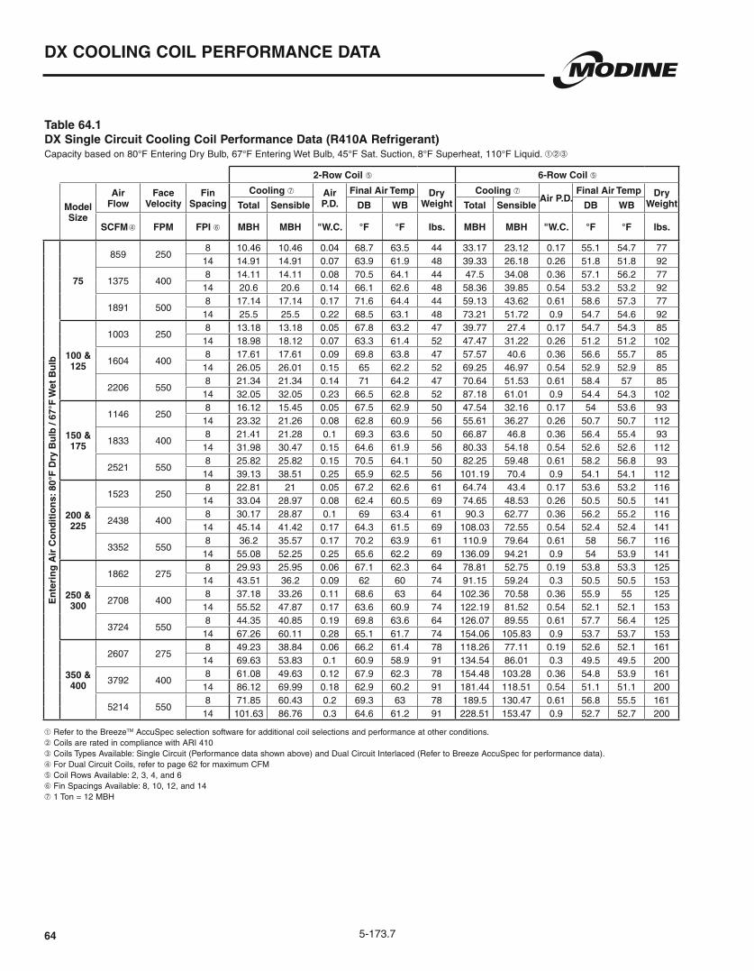
5-173.764
DX COOLING COIL PERFORMANCE DATA
Table 64.1 DX Single Circuit Cooling Coil Performance Data (R410A Refrigerant)
➀➁➂
➀ Refer to the BreezeTM AccuSpec selection software for additional coil selections and performance at other conditions. ➁ Coils are rated in compliance with ARI 410 ➂ Coils Types Available: Single Circuit (Performance data shown above) and Dual Circuit Interlaced (Refer to Breeze AccuSpec for performance data). ➃ For Dual Circuit Coils, refer to page 62 for maximum CFM➄ Coil Rows Available: 2, 3, 4, and 6➅ Fin Spacings Available: 8, 10, 12, and 14➆ 1 Ton = 12 MBH
2-Row Coil ➄ 6-Row Coil ➄
Model Size
Air Flow
Face Velocity
Fin Spacing
Cooling ➆ Air P.D.
Final Air Temp Dry Weight
Cooling ➆Air P.D.
Final Air Temp Dry WeightTotal Sensible DB WB Total Sensible DB WB
SCFM ➃ FPM FPI ➅ MBH MBH "W.C. °F °F lbs. MBH MBH "W.C. °F °F lbs.
En
teri
ng
Air
Co
nd
itio
ns:
80°
F D
ry B
ulb
/ 67
°F W
et B
ulb
75
859 250 8 10.46 10.46 0.04 68.7 63.5 44 33.17 23.12 0.17 55.1 54.7 7714 14.91 14.91 0.07 63.9 61.9 48 39.33 26.18 0.26 51.8 51.8 92
1375 400 8 14.11 14.11 0.08 70.5 64.1 44 47.5 34.08 0.36 57.1 56.2 7714 20.6 20.6 0.14 66.1 62.6 48 58.36 39.85 0.54 53.2 53.2 92
1891 500 8 17.14 17.14 0.17 71.6 64.4 44 59.13 43.62 0.61 58.6 57.3 7714 25.5 25.5 0.22 68.5 63.1 48 73.21 51.72 0.9 54.7 54.6 92
100 & 125
1003 250 8 13.18 13.18 0.05 67.8 63.2 47 39.77 27.4 0.17 54.7 54.3 8514 18.98 18.12 0.07 63.3 61.4 52 47.47 31.22 0.26 51.2 51.2 102
1604 400 8 17.61 17.61 0.09 69.8 63.8 47 57.57 40.6 0.36 56.6 55.7 8514 26.05 26.01 0.15 65 62.2 52 69.25 46.97 0.54 52.9 52.9 85
2206 550 8 21.34 21.34 0.14 71 64.2 47 70.64 51.53 0.61 58.4 57 8514 32.05 32.05 0.23 66.5 62.8 52 87.18 61.01 0.9 54.4 54.3 102
150 & 175
1146 250 8 16.12 15.45 0.05 67.5 62.9 50 47.54 32.16 0.17 54 53.6 9314 23.32 21.26 0.08 62.8 60.9 56 55.61 36.27 0.26 50.7 50.7 112
1833 400 8 21.41 21.28 0.1 69.3 63.6 50 66.87 46.8 0.36 56.4 55.4 9314 31.98 30.47 0.15 64.6 61.9 56 80.33 54.18 0.54 52.6 52.6 112
2521 550 8 25.82 25.82 0.15 70.5 64.1 50 82.25 59.48 0.61 58.2 56.8 9314 39.13 38.51 0.25 65.9 62.5 56 101.19 70.4 0.9 54.1 54.1 112
200 & 225
1523 250 8 22.81 21 0.05 67.2 62.6 61 64.74 43.4 0.17 53.6 53.2 11614 33.04 28.97 0.08 62.4 60.5 69 74.65 48.53 0.26 50.5 50.5 141
2438 400 8 30.17 28.87 0.1 69 63.4 61 90.3 62.77 0.36 56.2 55.2 11614 45.14 41.42 0.17 64.3 61.5 69 108.03 72.55 0.54 52.4 52.4 141
3352 550 8 36.2 35.57 0.17 70.2 63.9 61 110.9 79.64 0.61 58 56.7 11614 55.08 52.25 0.25 65.6 62.2 69 136.09 94.21 0.9 54 53.9 141
250 & 300
1862 275 8 29.93 25.95 0.06 67.1 62.3 64 78.81 52.75 0.19 53.8 53.3 12514 43.51 36.2 0.09 62 60 74 91.15 59.24 0.3 50.5 50.5 153
2708 400 8 37.18 33.26 0.11 68.6 63 64 102.36 70.58 0.36 55.9 55 12514 55.52 47.87 0.17 63.6 60.9 74 122.19 81.52 0.54 52.1 52.1 153
3724 550 8 44.35 40.85 0.19 69.8 63.6 64 126.07 89.55 0.61 57.7 56.4 12514 67.26 60.11 0.28 65.1 61.7 74 154.06 105.83 0.9 53.7 53.7 153
350 & 400
2607 275 8 49.23 38.84 0.06 66.2 61.4 78 118.26 77.11 0.19 52.6 52.1 16114 69.63 53.83 0.1 60.9 58.9 91 134.54 86.01 0.3 49.5 49.5 200
3792 4008 61.08 49.63 0.12 67.9 62.3 78 154.48 103.28 0.36 54.8 53.9 16114 86.12 69.99 0.18 62.9 60.2 91 181.44 118.51 0.54 51.1 51.1 200
5214 5508 71.85 60.43 0.2 69.3 63 78 189.5 130.47 0.61 56.8 55.5 16114 101.63 86.76 0.3 64.6 61.2 91 228.51 153.47 0.9 52.7 52.7 200

5-173.7 65
DX COOLING COIL PERFORMANCE DATA
Table 65.1 DX Single Circuit Cooling Coil Performance Data (R410A Refrigerant)
➀➁➂
➀ Refer to the BreezeTM AccuSpec selection software for additional coil selections and performance at other conditions. ➁ Coils are rated in compliance with ARI 410 ➂ Coils Types Available: Single Circuit (Performance data shown above) and Dual Circuit Interlaced (Refer to Breeze AccuSpec for performance data). ➃ For Dual Circuit Coils, refer to page 62 for maximum CFM➄ Coil Rows Available: 2, 3, 4, and 6➅ Fin Spacings Available: 8, 10, 12, and 14➆ 1 Ton = 12 MBH
2-Row Coil ➄ 6-Row Coil ➄
Model Size
Air Flow
Face Velocity
Fin Spacing
Cooling ➆ Air P.D.
Final Air Temp Dry Weight
Cooling ➆ Air P.D.
Final Air Temp Dry WeightTotal Sensible DB WB Total Sensible DB WB
SCFM ➃ FPM FPI ➅ MBH MBH "W.C. °F °F lbs. MBH MBH "W.C. °F °F lbs.
En
teri
ng
Air
Co
nd
itio
ns:
95°
F D
ry B
ulb
/ 75
°F W
et B
ulb
75
859 250 8 22.11 18.02 0.06 75.6 68.5 44 57.65 35.95 0.17 56.2 55.6 7714 31.8 24.84 0.09 68.2 65.3 48 65.9 40.12 0.26 51.8 51.8 92
1375 400 8 28.94 24.68 0.12 78.4 69.7 44 81.03 52.16 0.36 59.9 58.5 7714 43.12 35.37 0.18 71.2 66.9 48 96.46 60.32 0.54 54.4 54.4 92
1891 500 8 34.3 30.3 0.2 80.2 70.5 44 100.12 66.33 0.61 62.5 60.5 7714 52.27 44.53 0.28 73.2 68 48 122.58 78.61 0.9 56.5 56.4 92
100 & 125
1003 2508 28.02 21.69 0.06 75 67.9 47 68.15 42.31 0.17 55.9 55.3 8514 39.84 29.87 0.09 67.4 64.5 52 77.48 47.08 0.26 51.5 51.5 102
1604 400 8 36.65 29.62 0.12 77.9 69.3 47 95.87 61.34 0.36 59.6 58.2 8514 54.11 42.43 0.18 70.5 66.3 52 113.79 70.87 0.54 54.1 54.1 102
2206 550 8 43.47 36.33 0.2 79.8 70.1 47 119.01 78.15 0.61 62.2 60.1 8514 63.89 52.81 0.3 72.8 67.6 52 144.64 92.32 0.9 56.2 56.2 102
150 & 175
1146 250 8 33.88 25.34 0.06 74.5 67.4 50 78.64 48.65 0.17 55.7 55.1 9314 47.96 34.9 0.09 66.8 63.9 56 89.3 54.12 0.26 51.3 51.3 112
1833 400 8 44.66 34.65 0.12 77.5 68.9 50 110.72 70.55 0.36 59.4 58 9314 63.96 49.15 0.18 70.2 65.9 56 131.05 81.39 0.54 53.9 53.9 112
2521 550 8 52.94 42.45 0.2 79.4 69.8 50 137.04 89.67 0.61 62.1 60 9314 75.3 61.05 0.3 72.6 67.4 56 166.49 105.97 0.9 56.1 56 112
200 & 225
1523 250 8 47.3 34.37 0.06 74.1 67 61 105.31 64.96 0.17 55.5 54.9 11614 66.62 47.35 0.09 66.2 63.3 69 119.49 72.28 0.26 51.1 51.1 141
2438 400 8 62.01 46.85 0.12 77.2 68.6 61 148.38 94.27 0.36 59.2 57.8 11614 87.23 66.05 0.18 69.9 65.7 69 175.15 108.58 0.54 53.8 53.8 141
3352 550 8 77.28 57.12 0.2 79.2 69.6 61 183.82 119.83 0.61 61.9 59.8 11614 102.76 81.95 0.3 72.4 67.1 69 222.22 141.23 0.9 56 55.9 141
250 & 300
1862 275 8 59.86 42.01 0.06 74.1 66.7 64 127.09 78.52 0.19 56 55.2 12514 82.5 57.71 0.1 66.3 63.2 74 145.34 88 0.3 51.2 51.2 153
2708 400 8 73.22 53.32 0.12 76.8 68.1 64 166.89 105.47 0.36 58.9 57.6 12514 101.97 74.97 0.18 69.4 65.2 74 196.32 121.35 0.54 53.5 53.5 153
3724 550 8 84.95 64.66 0.2 78.9 69.3 64 205.58 133.58 0.61 61.8 59.7 12514 120.95 93.12 0.3 71.8 66.6 74 248.81 157.69 0.9 55.8 55.7 153
350 & 400
2607 275 8 88.86 60.38 0.06 73.6 66.2 78 186.77 113.46 0.19 54.7 54 16114 121.91 82.94 0.1 65.5 62.4 91 209.42 125.77 0.3 50.3 50.3 200
3792 4008 108.28 76.37 0.12 76.4 67.7 78 242.62 151.11 0.36 58.1 56.7 16114 151.51 107.76 0.18 68.7 64.5 91 281.08 172.47 0.54 52.9 52.9 200
5214 5508 126.08 92.54 0.2 78.6 68.9 78 297.74 190.6 0.61 61.2 59.1 16114 179.36 133.46 0.3 71.3 66.1 91 353.49 222.79 0.9 55.4 55.4 200
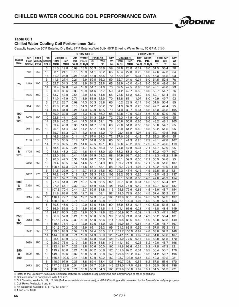
5-173.766
CHILLED WATER COOLING COIL PERFORMANCE DATA
Model Size
Table 66.1 Chilled Water Cooling Coil Performance Data Capacity based on 80°F Entering Dry Bulb, 67°F Entering Wet Bulb, 45°F Entering Water Temp, 70 GPM. ➀➁➂
6 31.0 19.8 0.09 13.9 56.3 53.8 59 37.8 23.8 0.14 16.0 51.5 50.4 76 10 38.1 24.1 0.15 13.9 51.1 50.2 65 43.4 27.0 0.23 16.0 47.6 47.3 84 14 41.2 25.9 0.21 13.9 48.9 48.5 70 45.4 28.1 0.31 16.0 46.3 46.2 93 6 41.6 27.4 0.21 13.9 59.5 56.2 59 52.7 34.0 0.31 16.0 54.5 52.8 76 10 52.7 34.3 0.32 13.9 54.2 52.8 65 62.9 40.0 0.49 16.0 50.0 49.6 84 14 58.4 37.8 0.44 13.9 51.7 51.0 70 67.5 42.5 0.65 16.0 48.1 48.0 93 6 50.0 33.6 0.36 13.9 61.6 57.7 59 64.2 42.7 0.55 16.0 56.7 54.7 76 10 63.7 43.0 0.54 13.9 56.6 54.8 65 78.5 51.2 0.82 16.0 52.1 51.4 84 14 71.9 47.9 0.71 13.9 53.9 52.9 70 85.8 55.1 1.07 16.0 49.9 49.7 93 6 37.2 23.7 0.09 14.3 56.3 53.8 66 45.2 28.5 0.14 16.6 51.5 50.4 85 10 45.6 28.8 0.15 14.3 51.2 50.2 72 51.9 32.3 0.23 16.6 47.7 47.4 95 14 49.4 31.0 0.21 14.3 48.9 48.5 79 54.3 33.7 0.31 16.6 46.3 46.3 105 6 50.0 32.8 0.21 14.3 59.5 56.2 66 62.8 40.6 0.31 16.6 54.6 52.9 85 10 62.8 41.1 0.32 14.3 54.3 52.9 72 75.3 47.9 0.49 16.6 50.1 49.6 95 14 69.9 45.2 0.44 14.3 51.8 51.1 79 80.6 50.8 0.65 16.6 48.2 48.1 105 6 59.4 40.3 0.36 14.3 61.7 57.8 66 77.0 51.0 0.55 16.6 56.8 54.7 85 10 76.1 51.4 0.54 14.2 56.7 54.8 72 93.9 61.2 0.82 16.5 52.2 51.5 95 14 85.7 57.3 0.71 14.2 54.0 53.0 79 102.4 65.9 1.07 16.5 50.1 49.8 105 6 46.5 29.8 0.11 14.7 57.0 54.3 72 57.0 36.1 0.16 17.2 52.2 50.9 95 10 57.5 36.5 0.18 14.7 51.8 50.8 80 66.1 41.3 0.26 17.2 48.1 47.8 107 14 62.6 39.5 0.24 14.6 49.5 49.1 88 69.6 43.2 0.36 17.2 46.7 46.6 119 6 58.4 38.5 0.21 14.7 59.6 56.3 72 74.0 47.8 0.31 17.1 54.7 52.9 95 10 73.8 48.2 0.32 14.6 54.4 53.0 80 88.3 56.3 0.49 17.1 50.2 49.7 107 14 82.0 53.1 0.44 14.6 51.9 51.2 88 94.9 59.7 0.65 17.1 48.3 48.2 119 6 70.0 47.5 0.36 14.6 61.7 57.8 72 90.1 59.9 0.55 17.1 56.9 54.8 95 10 89.4 60.5 0.54 14.6 56.7 54.9 80 109.7 71.9 0.82 17.1 52.3 51.6 107 14 100.4 67.3 0.71 14.6 54.1 53.1 88 120.1 77.4 1.07 17.1 50.2 49.9 119 6 61.8 39.9 0.11 12.7 57.3 54.6 92 79.2 48.4 0.16 14.5 52.5 51.2 121 10 76.2 48.7 0.18 12.7 52.3 51.2 103 88.2 55.3 0.26 14.5 48.5 48.2 137 14 83.1 52.7 0.24 12.7 50.0 49.5 113 93.1 58.0 0.36 14.5 47.0 46.9 154 6 77.3 51.3 0.21 12.7 59.9 56.5 92 97.7 63.8 0.31 14.5 55.1 53.4 121 10 97.0 64.1 0.32 12.7 54.9 53.5 103 116.5 74.9 0.49 14.5 50.7 50.2 137 14 107.5 70.4 0.44 12.7 52.5 51.8 113 125.5 79.6 0.65 14.5 48.9 48.7 154 6 91.8 63.0 0.36 12.7 62.1 58.1 92 118.3 79.5 0.55 14.5 57.4 55.2 121 10 116.4 79.7 0.54 12.7 57.3 55.4 103 143.8 95.1 0.82 14.5 52.9 52.2 137 14 130.5 88.7 0.71 12.7 54.8 53.8 113 157.1 102.3 1.07 14.5 50.9 50.6 154 6 70.5 45.6 0.12 12.9 57.6 54.8 99 86.9 55.3 0.17 14.9 52.8 51.5 131 10 86.9 55.8 0.19 12.9 52.6 51.5 111 101.1 63.6 0.28 14.9 48.8 48.4 149 14 94.7 60.5 0.26 12.9 50.3 49.8 123 106.9 66.7 0.39 14.9 47.3 47.1 167 6 86.0 57.3 0.21 12.9 60.0 56.6 99 108.8 71.0 0.31 14.9 55.2 53.4 131 10 107.6 71.5 0.32 12.9 55.0 53.6 111 129.8 83.5 0.49 14.9 50.8 50.3 149 14 119.4 78.4 0.11 12.9 52.6 51.9 123 139.9 88.7 0.65 14.8 49.0 48.7 167 6 101.5 70.2 0.36 12.9 62.1 58.2 99 131.2 88.5 0.55 14.9 57.5 55.3 131 10 129.0 88.9 0.54 12.9 57.4 55.5 111 159.7 105.9 0.82 14.8 53.0 52.3 149 14 144.8 98.8 0.71 12.9 54.9 53.9 123 174.1 113.8 1.07 14.8 51.0 50.8 167 6 98.4 63.9 0.12 13.8 57.8 55.0 126 121.0 77.6 0.17 16.2 53.0 51.8 170 10 120.9 78.0 0.19 13.8 52.9 51.8 143 141.1 89.1 0.28 16.2 49.0 48.7 196 14 132.4 84.7 0.26 13.8 50.6 50.0 160 149.6 93.6 0.39 16.2 47.5 47.3 221 6 119.2 80.0 0.21 13.8 60.2 56.8 126 151.0 99.2 0.31 16.2 55.4 53.7 170 10 149.3 99.6 0.32 13.8 55.3 53.8 143 179.8 116.2 0.49 16.2 51.2 50.7 196 14 165.6 109.5 0.44 13.8 52.9 52.2 160 193.7 123.9 0.65 16.2 49.3 49.2 221 6 140.9 97.9 0.36 13.8 62.4 58.4 126 180.7 123.1 0.55 16.2 57.8 55.6 170 10 177.5 123.8 0.54 13.8 57.7 55.8 143 219.0 147.0 0.82 16.1 53.5 52.8 196 14 198.6 136.8 0.71 13.8 55.3 54.3 160 239.6 158.0 1.07 16.1 51.5 51.3 221
75
100&
125
150&
175
200&
225
250&
300
350&
400
4-Row Coil ➃ 6-Row Coil ➃
Cooling ➅
762 250
1219 400
1676 550
914 250
1463 400
2011 550
1186 275
1725 400
2372 550
1607 275
2338 400
3214 550
1861 285
2613 400
3592 550
2629 285
3690 400
5073 550
➀ Refer to the BreezeTM AccuSpec selection software for additional coil selections and performance at other conditions. ➁ Coils are rated in compliance with ARI 410 ➂ Coil Circuiting Available: 1/4, 1/2, 3/4 (Performance data shown above), and Full Circuiting and is calculated by the BreezeTM AccuSpec program. ➃ Coil Rows Available: 4 and 6➄ Fin Spacings Available: 6, 8, 10, 12, and 14➅ 1 Ton = 12 MBH
Cooling ➅ Air Face Fin Air Water Final Air Dry Dry Water Final Air Dry Flow Velocity Spacing Total Sen P.D. P.D. ➂ DB WB Wt Total Sen P.D. P.D. DB WB Wt SCFM FPM FPI ➄ MBH MBH "W.C. Ft H2O °F °F lbs MBH MBH "W.C. Ft H2O °F °F lbs

5-173.7 67
Model Size
Table 67.1 Chilled Water Cooling Coil Performance Data Capacity based on 95°F Entering Dry Bulb, 75°F Entering Wet Bulb, 45°F Entering Water Temp, 70 GPM. ➀➁➂
6 46.0 28.0 0.09 13.9 61.5 57.8 59 56.1 33.7 0.14 16.0 54.6 53.0 76 10 56.6 34.0 0.15 13.9 54.2 52.8 65 64.5 38.3 0.23 16.0 49.0 48.7 84 14 61.3 36.7 0.21 13.9 51.0 50.4 70 67.6 39.9 0.31 16.0 47.1 47.0 93 6 61.5 38.6 0.21 13.9 66.0 61.1 59 77.9 48.0 0.31 16.0 59.0 56.6 76 10 77.6 48.4 0.32 13.9 58.7 56.7 65 93.3 56.5 0.49 16.0 52.6 51.9 84 14 86.4 53.3 0.44 13.9 55.0 54.1 70 100.1 60.1 0.65 16.0 49.9 49.8 93 6 73.2 47.5 0.36 13.9 69.1 63.2 59 95.1 60.2 0.55 16.0 62.2 59.0 76 10 93.6 60.5 0.54 13.9 62.0 59.3 65 116.0 72.1 0.82 16.0 22.7 54.7 84 14 105.7 67.4 0.71 13.9 58.2 56.9 70 126.7 77.7 1.07 16.0 52.6 52.3 93 6 55.2 33.5 0.09 14.3 61.5 57.8 66 67.2 40.4 0.14 16.6 54.6 53.1 85 10 67.7 40.7 0.15 14.3 54.3 52.9 72 77.2 45.8 0.23 16.6 49.2 48.8 95 14 73.3 43.9 0.21 14.2 51.0 50.5 79 80.9 47.8 0.31 16.5 47.2 47.1 105 6 73.5 46.2 0.21 14.2 66.1 61.2 66 93.2 57.5 0.31 16.5 59.1 56.7 85 10 92.9 57.9 0.32 14.2 58.8 56.7 72 111.1 67.6 0.49 16.5 52.8 52.1 95 14 103.2 63.7 0.44 14.2 55.2 54.2 79 119.8 71.9 0.65 16.5 50.1 49.8 105 6 87.4 56.8 0.36 14.2 69.2 63.3 66 113.2 71.8 0.55 16.5 62.3 59.2 85 10 111.9 72.3 0.54 14.2 62.1 59.4 72 138.4 86.3 0.82 16.5 55.8 54.8 95 14 126.1 80.6 0.71 14.2 58.4 57.0 79 151.4 92.9 1.07 16.5 52.7 52.4 105 6 69.0 42.2 0.11 14.6 62.4 58.6 72 84.8 51.2 0.16 17.1 55.5 53.9 95 10 85.2 51.6 0.18 14.6 55.2 53.7 80 98.4 58.6 0.26 17.1 49.8 49.4 107 14 92.9 55.9 0.24 14.6 51.9 51.3 88 103.5 61.3 0.36 17.1 47.8 47.6 119 6 86.3 54.4 0.21 14.6 66.2 61.2 72 109.6 67.6 0.31 17.1 59.2 56.7 95 10 108.9 68.1 0.32 14.6 58.9 56.9 80 130.8 79.4 0.49 17.1 52.9 52.2 107 14 121.0 74.9 0.44 14.6 55.3 54.3 88 140.7 84.5 0.65 17.1 50.2 50.0 119 6 102.6 66.8 0.36 14.6 69.3 63.4 72 133.1 84.5 0.55 17.1 62.4 59.3 95 10 131.1 85.0 0.54 14.6 62.3 59.5 80 162.4 101.3 0.82 17.1 56.0 54.9 107 14 147.8 94.7 0.71 14.6 58.5 57.1 88 177.2 109.1 1.07 17.0 52.9 52.6 119 6 91.5 56.3 0.11 12.7 63.0 59.0 92 112.8 68.4 0.16 14.5 56.1 54.3 121 10 112.5 68.8 0.18 12.7 55.8 54.4 103 130.8 78.3 0.26 14.5 50.4 50.0 137 14 123.0 74.4 0.24 12.7 52.7 51.9 113 138.4 82.1 0.36 14.5 48.3 48.1 154 6 114.0 72.4 0.21 12.7 66.7 61.6 92 144.4 90.0 0.31 14.5 59.8 57.3 121 10 142.9 90.2 0.32 12.6 59.7 57.5 103 172.2 105.7 0.49 14.5 53.7 53.0 137 14 158.3 99.1 0.44 12.6 56.3 55.2 113 185.5 112.5 0.65 14.5 51.0 50.8 154 6 134.6 88.7 0.36 12.7 69.8 63.8 92 174.3 112.1 0.55 14.5 63.1 59.9 121 10 170.2 112.3 0.54 12.6 63.1 60.3 103 211.5 133.8 0.82 14.4 56.9 55.9 137 14 190.6 124.6 0.71 12.6 59.6 58.2 113 231.4 144.1 1.07 14.4 54.0 53.6 154 6 104.1 64.4 0.12 12.9 63.3 59.3 99 128.9 78.3 0.17 14.9 56.5 54.7 131 10 128.5 78.7 0.19 12.9 56.3 54.7 111 149.9 89.9 0.28 14.8 50.8 50.4 149 14 140.4 85.4 0.26 12.9 53.0 52.3 123 158.7 94.5 0.39 14.8 48.6 48.5 167 6 126.8 80.8 0.21 12.9 66.7 61.7 99 160.8 100.2 0.31 14.8 59.9 57.4 131 10 158.7 100.4 0.32 12.9 59.9 57.7 111 191.5 117.7 0.49 14.8 53.8 53.2 149 14 175.9 110.4 0.11 12.9 56.4 55.4 123 206.4 125.1 0.65 14.8 51.2 51.0 167 6 149.7 98.8 0.36 12.9 69.8 63.8 99 193.3 124.6 0.55 14.8 63.3 60.0 131 10 188.7 125.1 0.54 12.8 63.2 60.4 111 235.0 149.1 0.82 14.8 57.1 56.0 149 14 211.5 138.7 0.71 12.8 59.7 58.3 123 255.9 160.0 1.07 14.7 54.3 53.9 167 6 285.0 145.4 0.12 13.8 63.6 59.5 126 179.6 109.6 0.17 16.2 56.9 55.0 170 10 179.1 110.1 0.19 13.8 56.7 55.1 143 209.0 125.9 0.28 16.2 51.2 50.8 196 14 195.5 119.5 0.26 13.8 53.4 52.8 160 222.0 132.5 0.39 16.1 48.9 48.8 221 6 175.9 112.7 0.21 13.8 67.1 62.0 126 222.7 139.7 0.31 16.1 60.4 57.8 170 10 219.7 140.2 0.32 13.7 60.3 58.1 143 265.0 163.9 0.49 16.1 54.4 53.7 196 14 243.5 153.8 0.44 13.7 56.9 55.8 160 286.2 174.5 0.65 16.1 51.8 51.5 221 6 206.7 137.8 0.36 13.7 70.2 64.1 126 265.5 173.3 0.55 16.1 63.8 60.5 170 10 260.0 173.8 0.54 13.7 63.7 60.8 143 322.0 206.3 0.82 16.1 57.8 56.7 196 14 289.5 192.1 0.71 13.7 60.4 58.9 160 351.0 221.8 1.07 16.0 55.0 54.7 221
75
100&
125
150&
175
200&
225
250&
300
350&
400
4-Row Coil ➃ 6-Row Coil ➃
762 250
1219 400
1676 550
914 250
1463 400
2011 550
1186 275
1725 400
2372 550
1607 275
2338 400
3214 550
1861 285
2613 400
3592 550
2629 285
3690 400
5073 550
CHILLED WATER COOLING COIL PERFORMANCE DATA
Cooling ➅ Cooling ➅ Air Face Fin Air Water Final Air Dry Air Water Final Air Dry Flow Velocity Spacing Total Sen P.D. P.D. ➂ DB WB Wt Total Sen P.D. P.D. ➂ DB WB Wt SCFM FPM FPI ➄ MBH MBH "W.C. Ft H2O °F °F lbs MBH MBH "W.C. Ft H2O °F °F lbs
➀ Refer to the BreezeTM AccuSpec selection software for additional coil selections and performance at other conditions. ➁ Coils are rated in compliance with ARI 410 ➂ Coil Circuiting Available: 1/4, 1/2, 3/4 (Performance data shown above), and Full Circuiting and is calculated by the BreezeTM AccuSpec program. ➃ Coil Rows Available: 4 and 6➄ Fin Spacings Available: 6, 8, 10, 12, and 14➅ 1 Ton = 12 MBH

5-173.768
Model Size FH H S V FL I L Supply Line Return Line
75 27 30 1.5 1.5 16.25 25.50 19.25 1.50 MPT 1.50 MPT
100/125 27 30 1.5 1.5 19.50 28.75 22.50 1.50 MPT 1.50 MPT
150/175 27 30 1.5 1.5 23.00 32.25 26.00 1.50 MPT 1.50 MPT
200/225 33 34.5 0.5 1 25.50 34.75 28.50 1.50 MPT 1.50 MPT
250/300 33 34.5 0.5 1 28.50 37.75 31.50 1.50 MPT 1.50 MPT
350/400 33 34.5 0.5 1 40.25 49.50 43.25 1.50 MPT 1.50 MPT
Figure 68.1 - DX Coil Drawing (All dimensions in inches)
Table 68.1 - DX Coil Dimensions
Table 68.2 - Chilled Water Coil Dimensions
Figure 68.2 - Chilled Water Coil Drawing (All dimensions in inches)
COOLING COIL DIMENSIONS
Rows 4 6 W 7.5 10
Rows 2 3 4 6 W 7.5 6 7.5 10
L
1.5 1.5
H
W
1.5
I
AirflowDirection
TOP VIEW
FL
FH
Airflow Direction
SCoil for Right Hand Units (Digit 9 = R)
Headers on opposite side for Left Hand Units
Suction Line Connection(s) in direction of airflow
(Second Inlet on Dual Circuit Coils)
Distributor Inlet (Liquid Line) Connection(s)
(Second Inlet on Dual Circuit Coils)
FRONT VIEW SIDE VIEW
1.5 1.5
H
W
V
I
Airflow Direction
TOP VIEW
FH
Airflow Direction
S
1.8
1.8
2.25
2.25
Connection turned 90° in
direction of airflow
Connection turned 90° in
direction of airflow
Coil for Right Hand Units (Digit 9 = R)
Headers on opposite side for FRONT VIEW
SIDE VIEW
Model Size Cooling MBH FH H SSingle Circuit Dual Circuit
FL I L FL I L
75 All 28 31 2 18 25 21 16 27 19
100/125 All 28 31 2 21 28 24 20 30 23150/175 All 28 31 2 24 31 27 23 33 26
200/225Below 185 33 35 0 27 34 30
26 36 29185 and Up 33 35 0 27 35 30
250/300Below 185 33 35 0 30 37 33
29 39 32185 and Up 33 35 0 30 38 33
350/400Below 185 33 35 0 42 49 45
40 51 43185 and Up 33 35 0 42 50 45

5-173.7
EVAPORATIVE COOLER SPECIFICATIONS
Evaporative Cooling ModuleAll Outdoor models that include a blower section can be provided with a factory installed and wired evaporative cooling module. When applicable, evaporative cooling is one of the most economical means of supplying conditioned air to a space.
Evaporative cooling works on the principle of exchanging sensible heat from the entering warm air to latent heat of vaporization of the cooling water. A special wetting media is placed in the entering air stream of the cooling unit and water is fed down the media. As the air passes through the media, sensible heat from the air is simply transferred to the water in the cooling media, causing the water to evaporate. Because the sensible heat from the air is simply transferred to the water, and both the water vapor and cooled air remain in the system, there is no net energy change in the system. However, the dry bulb temperature of the air has been lowered and provides cooling for the space.
The temperature of the cooling air will be dependent on three criteria. These criteria are: 1. The design dry bulb temperature 2. The design wet bulb temperature 3. The percent effectiveness of the cooling media
The design dry and wet bulb temperatures can be obtained from the climatic table of the ASHRAE Fundamentals Handbook. The percent effectiveness of the cooling media is determined from the media performance curves shown in Curve 70.1 for either the 6" or 12" media based on the velocity across the media. The velocity can be determined by dividing the desired CFM of the unit by the face area of the cooling media for the unit. The media face areas are shown in the Evaporative Cooler Dimensional, Performance, and Weight Data Table 70.1. All evaporative coolers are designed to meet face velocities of 800 feet per minute without water carryover, thus eliminating the need for moisture elimination pads. For media pressure drops, refer to the evaporative cooling pressure drops included with the unit blower performance curves.
Evaporative coolers are available with 2 types of media:® Celluose 6" and 12" media providing
brand name media performance.® Fiberglass 6" and 12" media which
is a fiberglass media material for applications requiring
Standard Features® evaporative cooling media.
polyester powder paint finish on exterior casing parts.
Optional Features - Factory Installed
® ® media.
208V/460V/575V/3Ph.
water level in the reservoir is below the switch.
Accessories - Field Installed
➀.
protection ➀.➀.
protection ➀.
Evaporative Cooling Performance ExampleDetermine the final dry bulb temperature for a model HBG200
media. The unit is to be installed in Phoenix, Arizona. The ASHRAE guide shows a design dry bulb temperature of 109°F and a design wet bulb temperature of 71°F. This is plotted as Point A on Figure 70.2. Also determine the apparent cooling capacity of the evaporative cooler.
1. Determine the face velocity across the media located in Table 70.1. Find the model size and blower type of the selected unit and then find the corresponding media face area (For the model size 200 and all blowers, the media face area is 7.5 ft2 of media). To calculate the face velocity:
FPM = CFM / Media Face Areaor 4321 CFM / 7.5 ft2 = 576 FPM
2. Determine the media percent effectiveness. Enter Figure 70.1 at 576 FPM and follow up the graph until the FPM line intersects with the 12" media % curve. At the point of intersection, read across to the left and find the percent effectiveness. For this example, the effectiveness is 89%.
3. Determine final dry bulb air temperature of conditioned air.
Once the final dry bulb temperature has been determined, the point of operation can be plotted on the psychrometric
constant so it is 71°F. This is plotted as Point B on Figure 70.2.
4. Determine the cooling capacity of the unit. The cooling capacity of the unit is defined as the apparent cooling capacity because it is dependent on a specific set of temperature conditions. As these conditions change, so will the apparent cooling capacity.
Q = 1.08 x (109°F - 75°F) x 4321 CFM = 158,667 Btu/Hr5. Determine the pressure drop across the media and
birdscreen. This number must be added to the internal static pressure of the unit when selecting a unit. This information is required to make a proper motor selection. The evaporative cooler pressure drop table can be found on page 36. Note that if the optional pre-filters are used, the proper pressure drop curve should be used.
Definition of TermsEAT = Entering Air Temperature
DB = Dry BulbWB = Wet Bulb% Eff. = Percent EffectivenessQ = Apparent Cooling Capacity
69
➀ Valves rated for 50 PSI maximum water pressure.

5-173.7
DIMENSIONS - EVAPORATIVE COOLER
70
6" Media ➀ 12" Media ➀
Face Velocity (Digit 23 = 3 or 5) (Digit 23 = 4 or 6)
Model Blower Type Maximum Media Face at Max CFM Dry Operating Dry Operating
Size (Digit 16) H W Cooling CFM Area (ft2) (ft/min) Weight Weight Weight Weight
75 All 34 30 2778 4.0 695 149 273 154 285
100/125 All 34 30 4000 5.0 800 154 280 159 295
150/175 All 34 36 5200 6.5 800 159 313 169 336
200/225 All 38 36 6000 7.5 800 164 318 174 341
250/300 E,F,G, or H 38 39 6500 8.1 800 171 338 182 363
250/300 I, J, or K 56 39 10400 13.0 800 200 371 214 404
350/400 E,F,G, or H 38 51 8500 10.6 800 211 433 228 473
350/400 I, J, or K 47 51 11050 13.8 800 225 450 244 496
500/600 G or H 38 39 6500 8.1 800 171 338 182 363
500/600
700/800 G or H 38 51 8500 10.6 800 211 433 228 473
700/800
840/960
Table 70.1Evaporative Cooler Dimensional, Performance, and Weight Data (All dimensions in inches)
➀ All weights in pounds.
Figure 70.3Evaporative Cooling Module
Dewpo
int o
r wet
-bulb
tem
pera
ture
F
Rel
ativ
e H
umid
ity
Rel
ativ
e H
umid
ity
10
10
12.0
12.5
13.0
13.5
14.0
14.5
15.0
15.5
20
20 30 40 50 60 70 80 90 100 110 120 130 140 150 160
200
190
180
170
160
150
140
160
120
110
100
90
80
70
60
50
40
30
20
10
30
40
50
60
70
80
Grains of moisture per pound of dry air
Dry-bulb temperature F
Cub
ic ft
. per
pou
nd o
f dry
air
90%
80%
80%
90%70%
50%
30%
10% 5%
60%40%20%
70%
60%
50%
40%
30%
20%
10%
5%
B
A
Temperature Range 0 -160 FBarometric Pressure 29.92 In. Mercury
Figure 70.1 Evaporative Cooling Effectiveness Curve
Figure 70.2 Psychrometric Chart
J-Box
Pump
Optional 1"Pre-Filter Rack
W/2 -1.50
3.00
3.00
1.50
4.50
1.25
1.25
W
BlowerSection
Leveling Legs
6" or 12" Media
.25
4.50
25.50
36.00
H
Top View
Side View
1/2" NPT Drain
1/2" NPT Overflow
1/2" NPT Drain
1/2" NPT Overflow
1/2" NPT Water Inlet

5-173.7 71
SPECIFICATIONS
These specifications cover unit(s) __________ shown on the equipment schedule and in the plans.
GeneralA. Standards All unit(s) shall include:
A.1. C.S.A. (Canadian Standards Association) design certification for use in both the US and Canada to the ANSI Z83.8 - latest revision, standard for “Gas Unit Heater and Gas-Fired Duct Furnaces” for safe operation, construction, and performance.
Equipment” for electrical and mechanical safety.
B. Mechanical Configuration All unit(s) shall have right side (opt left side), when looking into the
discharge, access to all controls/venting and include:
B.1. Furnace(s) section with 80% minimum efficiency provided by an indirect-fired heat exchanger with dimpled tube pattern for efficient heat transfer.
B.2. Blower section containing a supply blower and motor with bottom support to provide rigidity. The blower connection shall be flexible with 1/4" gasket to prevent sound transmission into the supply ductwork.
B.3. Electrical section isolated from the supply air stream including a hinged access door. Separate knock-outs shall be provided for both high and low voltage electrical connections. Provisions must be included for side access electrical connections for slab mounted units and bottom electrical connections for roof curb mounted or suspended units.
B.4. Cooling coil cabinet section shall be shipped attached to and downstream of the heat exchanger. The blow through design shall prevent condensation on the heat exchanger in the cooling mode. The cabinet shall include a removable upper service access door and a stationary piping connection door. The drain pan shall be 409 stainless steel with drain and overflow connections.
Additional mechanical configurations for Outdoor onlyB.5. Downturn plenum section for downward deflection of the supply air.
B.6. Evaporative cooling section shall be factory installed and wired to the terminal strip of the electrical section.
B.7. Rainhood and birdscreen shall be pre-assembled from the factory and provided with internal baffles to prevent water entrainment in the supply air stream.
B.8. Roof curb with wood nailing strips and assembly hardware. The roof curb members shall be 16" high to meet the National Roofing Contractors Association requirements and constructed from 16 gauge aluminized steel. The curb shall include:
B.8.a. (opt) insulation.
B.8.b. (opt) discharge air duct connector for field installation of ductwork prior to unit arrival.
B.8.c. (opt) return air duct connector for field installation of ductwork prior to unit arrival.
C. Indoor Gravity Vented Venting ArrangementsC.1. The venting shall be gravity vented arrangement with a 45° angled
round vent connection to allow for tighter installation to duct system components.
C. Indoor Separated Combustion Venting ArrangementsC.2. The unit casing shall be designed for the venting/ combustion air
arrangement to be separated from the room atmosphere. The unit shall have a factory mounted power exhauster enclosed in the unit casing to
unit shall also include a factory mounted differential pressure switch designed to prevent pilot and main burner ignition until positive venting has been proven. A removable gasketed door shall contain both the vent and combustion air connection collars to allow for servicing of the power exhauster.
C.3. The unit shall include a factory supplied horizontal concentric vent kit allowing for a single penetration of the wall for both the combustion air supply and flue product exhaust.
C.4. The unit shall include a factory supplied vertical concentric vent kit allowing for a single penetration of the roof for both the combustion air supply and flue product exhaust.
C.5. The unit shall include two factory supplied vent caps for both the combustion air supply and flue product exhaust.
C. Outdoor Venting ArrangementsC.6. The venting shall be a gravity vented arrangement with a combination
combustion air / exhaust vent cap that minimizes the pressure differential between the inlet and exhaust of the venting system. This pressure differential shall reduce the burner flame disturbance to insure
velocities. The cap shall prevent rain from entering the unit through the use of combustion air inlet louvers at a minimum of 6 inches from the unit roof.
C.7. The venting shall be a power exhausted arrangement. The unit shall be
hour wind velocities.
D. Indoor Unit CasingD.1. The duct furnace(s) unit casing shall be constructed of not less than 20
gauge aluminized steel.
D.2. The blower and cooling sections shall be constructed of not less than 18 gauge aluminized steel.
D.3. All blower and cooling section exterior casing parts shall be painted with a baked-on gray-green polyester powder paint (7 mil thickness) for corrosion resistance.
D.4. All blower and cooling section access side doors shall have heavy duty, draw tight, quarter turn latches.
D.5. (opt) Blower and/or cooling sections shall include 1 inch, 1-1/2 lb density acoustical and thermal insulation. The insulation shall be made of glass fibers bonded with a thermosetting resin and overlaid with a fire-resistant black acrylic coating for additional strength. The acrylic coating must meet the requirements of ASTM C 665 for fungi resistance.
(opt) The blower and/or cooling sections shall include double wall construction in which 1 inch, 1-1/2 lb density insulation is covered by a 22 gauge aluminized steel liner. The liner shall conform to ASHRAE Standard 62-1989 Ventilation for Acceptable Indoor Air Quality.
Additional Unit Casing for Separated CombustionD.6. The duct furnace(s) shall include separate access doors for the power
exhauster, electrical controls, and gas train to allow for simplified service of the unit.
D.7. All duct furnace(s) doors shall be fully gasketed to prevent infiltration of the room air into the combustion process.
Outdoor Unit CasingD.8. The unit casing shall be constructed of not less than 18 gauge steel.
D.9. All exterior casing parts shall be painted with a baked-on gray-green polyester powder paint (7 mil thickness) for corrosion resistance.
D.10. All access side doors shall have heavy duty, draw tight, quarter turn latches.
D.11. Blower, cooling, and downturn sections when provided shall include 1 inch, 1-1/2 lb density acoustical and thermal insulation. The insulation shall be made of glass fibers bonded with a thermosetting resin and overlaid with a fire-resistant black acrylic coating for additional strength. The acrylic coating must meet the requirements of ASTM C 665 for fungi resistance.
D.12. (opt) The blower, cooling, and downturn sections when provided shall include double wall construction in which the standard insulation is covered by a 22 gauge aluminized steel liner. The liner shall conform to ASHRAE Standard 62-1989 Ventilation for Acceptable Indoor Air Quality.
E. Furnace SectionE.1. The heat exchanger(s) shall be made of
20 gauge aluminized steel tubes and headers (opt) 20 gauge 409 stainless steel tubes and headers
The thermal efficiency of the unit(s) shall be a minimum of 80% efficient for all air flow ranges. The restrictor shall be sized to maintain the unit(s) efficiency of 80% in the temperature range of 20°F-60°F or 20°F-100°F.
Each heat exchanger tube shall be individually and directly flame-fired. The heat exchanger tube shall be contoured and dimpled to provide efficient heat transfer and crimped to allow for thermal expansion and contraction. The flue collector box shall be made of 20 gauge aluminized steel.
E.2. The heat exchanger(s) seams and duct connections shall be certified to withstand 3.0" W.C. external static pressure without burner flame disturbance.
5-173.772
SPECIFICATIONS
E.3. The burner(s) shall be made of the same material as the heat exchanger with a thickness of not less than 28 gauge. Burner(s) shall have non-clogging, slotted ports with a stainless steel separator strip designed for good lighting characteristics without noise of extinction for both natural and propane gas. The burner(s) shall be located for service removal without disconnecting the main gas supply piping.
E.4. The bottom of the unit shall be angled for draining any condensation to the corners of the unit. The condensation shall be removed through openings in the bottom pan. The drain pan shall be constructed of 20 gauge aluminized steel.
(opt) 409 stainless steel.
E.5. The gas manifold(s) piping shall allow for gas piping connection on the side of the unit for slab mounted units and through the unit bottom for roof curb mounted or suspended units. The manifold(s) shall include a
the burner assembly or main gas valve string.
E.6. The orifices shall be provided on both natural and propane gas with
E.7. The ignition controller(s) shall be 100% shut-off with continuous retry for natural gas.
(opt) The ignition controller(s) shall be 100% shut-off with lockout for propane gas.
E.8. The gas pressure shall be between 6-7" W.C for natural gas.
(opt) The gas pressure shall be 11-14" W.C. for propane gas.
E.9. The solid state ignition system shall intermittently light the pilot each time the system is energized. Once the pilot is proven, the main gas valve shall open and allow gas flow to the main burner.
E.10. The unit gas controls shall be provided with the following:
E.10.a. Single-stage gas controls with a single-stage combination gas control, an ignition control, and a single-stage low voltage thermostat. The unit fires at 100% full fire based on a call for heat from a room thermostat.
E.10.b. (opt) Two-stage gas controls with a two-stage combination gas control, an ignition control, and a two-stage low voltage thermostat. The unit fires at 50% fire on low stage or 100% fire on high stage of the unit based on the call for heat from either a room or duct thermostat.
E.10.d. (opt) Electronic modulation gas controls with an electronic modulating/regulating gas control, combination gas valve, an ignition control, modulating amplifier, and either a modulating room thermostat or
The thermostat can modulate the system gas flow between 40% through 100% full fire. The firing rate shall be controlled by a
thermostat.
(opt) room thermostat.
E.10.e. (opt) Electronic Modulation Master gas controls with an electronic modulating/ regulating gas control, combination gas valve, an ignition control, modulating amplifier and either a modulating room thermostat or modulating duct thermostat with remote temperature set point
through 100% full fire. Allows one duct sensing thermostat to control the firing rate of the Master duct furnace and up to three Slave duct furnaces. The Master furnace sends a signal to all of the gas valves so that they modulate at the same percentage. When the thermostat is satisfied, the amplifier cuts power to the combination gas valves of the Master unit and all Slave units which prevents gas flow to both the main an pilot burners. The firing rate shall be controlled by a
thermostat.
(opt) room thermostat.
E.10.f. (opt) Electronic Modulation Slave gas controls with an electronic modulating/regulating gas control, combination gas valve, and an ignition control, but does not include a modulating amplifier and does not require a discharge air thermostat. The modulating gas valve receives the modulation percentage from the Master duct furnace. Up to three Slave duct furnaces can be connected to one Master unit.
E.10.g. (opt) Electronic Modulation - 0-10 Vdc External Input. Allows for control of the duct furnace firing rate by a Building Management System (BMS). Utilizes an electronic modulating/regulating gas control, combination gas valve, an ignition control, modulating signal conditioner, and an inverted 0-10 Vdc input signal provided by a BMS (0 Vdc being high fire and 10 Vdc being low fire). The gas controls can modulate the gas flow between 40% and 100% full fire. When the BMS thermostat (supplied by others) is satisfied, the BMS heat contact (supplied by others) opens to cut power to the combination gas valve which prevents gas flow to both the main and pilot burners.
E.10.h. (opt) Electronic Modulation - 4-20 mA External Input. Allows for control of the duct furnace firing rate by a Building Management System (BMS). Utilizes an electronic modulating/regulating gas control, combination gas valve, an ignition control, modulating signal conditioner, and an inverted 4-20 mA input signal provided by a BMS (4 mA being high fire and 20 mA being low fire). The gas controls can modulate the gas flow between 40% and 100% full fire. When the BMS thermostat (supplied by others) is satisfied, the BMS heat contact (supplied by others) opens to cut power to the combination gas valve which prevents gas flow to both the main and pilot burners.
E.11. A 1/8'' manifold pressure tap shall be located after all valves to test the manifold pressure directly before the main burner orifices.
E.12. The unit shall be provided with a single gas control transformer to step down the supply voltage to 24V.
E.13. Separate line voltage and low voltage terminal strips shall be provided to prevent the unit from being miswired for premium unit and low voltage terminals for standard units.
E.14. Automatic reset high limit switch.
(opt) Manual reset high limit switch.
E.15. Provide the following factory installed options:
E.15.a (opt) A low gas pressure switch(s) prevents the burner from firing if the inlet gas pressure is below the minimum gas pressure.
E.15.b. (opt) A high gas pressure switch(s) which prevents the burner from firing if the manifold gas pressure is above the maximum manifold gas pressure.
pressure switch to insure air flow across the heat exchanger before allowing the gas controls to be energized.
E.15.d. (opt) A timed freeze protection discharge air thermostat used to prevent building freeze up in the event of a burner failure. The timer
E.15.e. (opt) A manual reset supply air fire stat shall shut the system down if the temperature at the limit switch location exceeds 200°F.
E.15.f. (opt) A time delay relay which delays the start of the blower to allow the heat exchanger a warm-up period after a call for heat. The time delay relay shall also continue the blower operation after the thermostat has been satisfied to remove any residual heat on the heat exchanger.
E.16. The unit shall be orificed for up to 2000' elevation above sea level.
(opt) The unit shall be orificed for _____ elevation above sea level.
F. Electrical Section
F.2. The unit shall be supplied with a disconnect switch to disconnect power to the unit for servicing. The disconnect switch style shall be
(a) Dead-Front fusible.
(b) Dead-Front circuit breaker.
(c) field installed non-fusible box type.
(d) field installed fusible box type.
F.3. A single step down transformer shall be provided for all unit controls.F.4. For 460V and 575V units, a step down transformer from line voltage to
115V shall be provided for operation of the power exhauster motor.
5-173.7
G. Blower SectionG.1. The blower motor shall meet the following requirements.
G.1.a. The blower motor type shall be (a) Single-speed, open drip proof (ODP) (b) Single-speed, totally enclosed (TE) (c) Single-speed, ODP, high efficiency (ODP HE) (d) Single-speed, TE, high efficiency (TE HE)
G.1.b. The motor shall be rated for (a) 115V/60Hz/1Ph (e) 230V/60Hz/3Ph (b) 208V/60Hz/1Ph (f) 460V/60Hz/3Ph (c) 230V/60Hz/1Ph (g) 575V/60Hz/3Ph (d) 208V/60Hz/3Ph G.1.c. The motor horsepower shall be ____.
G.1.d. The motor wiring shall be in flexible metal BX conduit.
G.1.f. The motor shall be controlled by a time delay relay
(opt) and motor starter.
(opt) and variable frequency drive.
G.2. The unit shall contain a single supply blower that is supported from the bottom to prevent the blower flanges supporting the weight of the motor. The blower shall be a double width, double inlet (DWDI), forward curved, belt driven, assembly with
(std) spider ball bearings.
(opt) heavy duty, pillow block ball bearings.
(opt) motor and blower vibration isolation using rubber-in-shear grommets.
(opt) extended grease lines which include external zerk fittings for applying grease.
G.3. (opt) The unit shall be provided with a filter rack with
(a) 1" permanent filters (c) 2" FARR® Aeropleat 3 filters (MERV 7)
(b) 2" permanent filters (d) 2" FARR® 30/30 filters (MERV 8)
G.4. (opt) Dampers and Damper Controllers
G.4.a. All fresh air dampers are ultra low leak, Class II leakage resistance (less than 10 CFM/ft2 at 1" W.C.) dampers with self-compensating stainless steel side seals and santoprene and galvanized steel blade seals. All return air dampers, which are used for air balancing, shall be low leak, Class III leakage resistance (less than 40 CFM/ft2 at 1" W.C.) dampers with self-compensating stainless steel side seals and santoprene blade seals.
G.4.b. The damper actuator shall be mounted directly to the shaft of the fresh air damper. If return air dampers are provided, a damper linkage rod shall be provided to set the positions of the opposed dampers.
G.4.c. The damper actuator shall be spring return so when power is disconnected, the damper closes the outside air opening.
G.4.d. All two-position damper actuators shall have one normally open and one normally closed end switch to prove that the damper has opened.
G.4.e. Air Control AA - The unit shall be provided with a return air opening in the bottom of the unit.
G.4.f. Air Control BA - The unit shall be provided with a fresh air opening in the back of the unit.
G.4.g. Air Control CA = The unit shall be provided with fresh air and return air openings in both the bottom and the back of the unit.
G.4.h. Air Control DA = The unit shall be provided with fresh air dampers with a two-position damper motor with no return air.
G.4.i. Air Control EA = The unit shall be provided with fresh air and return air dampers with a two-position damper motor.
with fresh air and return air dampers with a two-position damper motor with warm-up thermostat.
G.4.k. Air Control FA = The unit shall be provided with fresh air dampers and return air opening with a two-position damper motor.
G.4.l. Air Control GA = The unit shall be provided with fresh air and return air dampers with a modulating damper motor with 0-10 Vdc external input signal control.
G.4.m. Air Control GB = The unit shall be provided with fresh air and return air dampers with a modulating damper motor with 4-20 mA external input signal control.
G.4.n. Air Control GC = The unit shall be provided with fresh air and return air dampers with a modulating damper motor with minimum positioner.
G.4.o. Air Control GD = The unit shall be provided with fresh air and return air dampers with a modulating damper motor with remote positioner.
G.4.p. Air Control GE = The unit shall be provided with fresh air and return air dampers with a modulating damper motor for three positions.
G.4.q. Air Control GF = The unit shall be provided with fresh air and return air dampers with a modulating damper motor with A350P proportional temperature controller.
G.4.r. Air Control GG = The unit shall be provided with fresh air and return air dampers with a modulating damper motor with minimum positioner and A350P proportional temperature controller.
G.4.s. Air Control GH = The unit shall be provided with fresh air and return air dampers with a modulating damper motor with remote positioner and A350P proportional temperature controller.
G.4.t. Air Control GJ = The unit shall be provided with fresh air and return air dampers with a modulating damper motor with fresh air enthalpy controller.
G.4.u. Air Control GK = The unit shall be meet ASHRAE Cycle II and be provided with fresh air and return air dampers with modulating a damper motor with minimum positioner, A350P proportional temperature controller, and warm-up thermostat.
G.4.v. Air Control GM = The unit shall meet ASHRAE Cycle II and be provided with fresh air and return air dampers with a modulating damper motor with remote positioner, A350P proportional temperature controller, and warm-up thermostat.
G.4.w. Air Control GN = The unit shall meet ASHRAE Cycle III and be provided with fresh air and return air dampers with a modulating damper motor with A350P proportional temperature controller, and warm-up thermostat.
G.4.x. Air Control HP = The unit shall be provided with fresh air and return air dampers with a floating damper motor with photohelic space pressure controller.
G.4.y. Air Control JA = The unit shall be provided with manual fresh air and return air dampers.
G.4.z. Air Control KA = The unit shall be provided with manual fresh air dampers and return air opening.
G.5. The unit shall be provided with the following factory installed options:
G.5.a. (opt) A mild temperature thermostat used to automatically lock out the gas controls when the outdoor temperature reaches the desired set point.
G.5.b. (opt) A manual reset return air fire stat that shuts the system down if the temperature in the blower section exceeds 120°F.
G.5.c. (opt) A blower door safety switch that breaks power to the unit low voltage control circuit when the blower door is opened. The switch can be manually overridden for servicing.
G.5.d. (opt) A set of three service switches for manual operation of the damper, blower, and burner by service personnel.
G.5.e. (opt) A convenience outlet with a 115V GFCI service receptacle mounted in the blower compartment for a separate 115V power supply.
G.5.f. (opt) A two-position damper limiter to manually fix the percentage of outside air for units with two-position fresh and return air dampers.
with pick-up tubes to monitor the filter pressure drop and energize a remote panel light if the set pressure is exceeded.
G.5.h. (opt) A circuit analyzer consisting of (6 or 10) lights that step through the sequence of operation for service personnel.
G.5.i. (opt) A fresh air discharge damper that is ultra low leak, Class II leakage resistance (less than 10 CFM/ft2 at 1" W.C.) dampers with self-compensating stainless steel side seals and santoprene and galvanized steel blade seals. The damper actuator shall be mounted directly to the shaft of the fresh air discharge damper. The damper actuator shall be spring return so when power is disconnected, the damper closes the outside air opening. The damper actuator shall have one normally open and one normally closed end switch to prove that the damper has opened.
H. Mounting BaseH.1. The unit shall be provided with a 14 gauge, galvanized steel, rail type mounting base for slab installation with lifting and anchoring holes.
H.2. The unit shall be provided with a 14 gauge, galvanized steel, combination curb and slab type mounting base with lifting and anchoring holes.
SPECIFICATIONS
73
5-173.774
I. Evaporative Cooler for Outdoor OnlyI.1. The unit shall be provided with
® ® media® ® media
I.2.a. The casing of the evaporative cooler shall be 18 gauge aluminized steel with a baked-on polyester power paint (7 mil thickness) for corrosion resistance.
I.2.b. The casing of the evaporative cooler shall be 18 gauge 304 stainless steel for corrosion resistance.
I.3. The water reservoir shall be 18 gauge 304 stainless steel.
I.4. The unit shall include a wire mesh birdscreen that is removable to allow front access to the pump motor, media, and water connections.
I.5. The pump motor shall have internal thermal overload protection.
of the evaporative cooler on the roof.
I.7. The evaporative cooler will be provided with the following factory installed controls:
I.7.a. A step down transformer for the pump motor.
I.7.b. A 1" permanent polyester cleanable pre-filter to prevent debris from entering the unit.
I.7.c. A float switch to prevent the pump motor from operating if the water level in the reservoir is below the switch.
I.7.d. A 1" aluminum mesh cleanable pre-filter to prevent debris from entering the unit.
I.8. The evaporative cooler will be provided with the following field installed controls:
I.8.a. A single stage duct thermostat to control the operation of the pump motor.
I.8.b. A manually operated remote fill and drain kit to fill the water reservoir when the unit is in cooling mode. When not in operation, the water shall be drained to prevent the recirculation of stagnant water.
I.8.c. A manually operated remote fill and drain kit with freeze protection to fill the water reservoir when the unit is in cooling mode. When not in cooling mode, the water shall be drained to prevent the recirculation of stagnant water. The freeze thermostat shall prevent the evaporative cooler from filling when the outside air temperature is below the set point.
I.8.d. An automatic fill and drain kit to fill the water reservoir, controlled by a time clock, when the unit is in cooling mode. When not in cooling mode, the water shall be drained to prevent the recirculation of stagnant water.
I.8.e. An automatic fill and drain kit with freeze protection to fill the water reservoir, controlled by a time clock, when the unit is in cooling mode. When not in cooling mode, the water shall be drained to prevent the recirculation of stagnant water. The freeze thermostat shall prevent the evaporative cooler from filling when the outside air temperature is below the set point.
J. Accessory Control Devices The following field installed accessory control devices shall be
provided with the unit:
J.1. A digital 7-day / 24-hour timer with SPDT switching. The timer shall have 16 programming set points with 7-day power outage carry-over.
J.2. A push pin style appliance timer with SPST switching with 12 settings per day (2 hour per pin time increments).
J.3. A mild temperature thermostat used to automatically lock out the gas controls when the outdoor temperature reaches the desired set point.
J.4. A low profile duct style photoelectronic smoke detector with two DPDT contacts.
J.4.a. A smoke detector tube extension for duct widths between 1 to 2 feet.
J.4.b. A smoke detector tube extension for duct widths between 2 to 4 feet.
J.4.c. A smoke detector tube extension for duct widths between 4 to 8 feet.
J.5. A freeze stat to shut the fresh air dampers if the outside temperature falls below the set point.
J.6. A 1-5 psi gas pressure regulator to reduce the inlet gas pressure for the operating controls.
J.7. A clear plastic thermostat guard with two keys for room thermostats.
J.8. A DPDT summer winter switch for continuous fan in the summer position and intermittent fan and burner in the winter position.
J.9. A remote manual positioner for controlling the percentage of fresh and return air on units provided with modulating damper actuators.
J.10. A 4 foot vent extension to increase the height of the unit exhaust.
J.11. A remote panel with the following
J.11.a. ___ indicator lights
J.11.b. ___ three position switch
J.11.c. ___ two position switches
J.11.d. ___ thermostat
J.11.e. ___ minimum damper positioner
K. Thermostats The unit shall be provided with the following thermostat
K.1. A single stage room thermostat with a 55°-95°F range.
K.2. A single stage room thermostat with a 45°-75°F range
K.3. A single stage room thermostat with a 45°-75°F range with sub-base for System auto/off and Fan auto/on control.
K.4. A 7-day programmable room thermostat with with one heat and one cool stage. The thermostat shall have Fan on/auto and System heat/off/cool/auto switching. Programmable for 2 to 4 events per day with override feature and one auxiliary output terminal for damper control.
K.5. A two-stage room thermostat with a 42°-88°F range.
K.6. A two-stage room thermostat with a 42°-88°F range with sub-base for System auto/off and Fan auto/on control.
K.7. A 7-day programmable room thermostat with with two heat and two cool stages. The thermostat shall have Fan on/auto and System heat/off/cool/auto switching. Programmable for 2 to 4 events per day with override feature and one auxiliary output terminal for damper control.
K.8. A factory installed two-stage duct thermostat with a 0°-100°F range and 20 foot capillary.
K.9. A field installed two-stage duct thermostat with a 0°-100°F range and 20 foot capillary.
K.10. A factory installed two-stage duct thermostat with a 55°-175°F range and 20 foot capillary.
K.11. A field installed two-stage duct thermostat with a 55°-175°F range and 20 foot capillary.
K.12. A two-stage electronic duct thermostat with factory installed temperature sensor and field installed temperature selector and one (up to two) stage adder.
K.13. A two-stage electronic duct thermostat with field installed temperature sensor, temperature selector and one (up to two) stage adder.
K.14. A factory installed electronic modulating duct thermostat with a range of 55°-90°F.
thermostat.
K.16. A field installed electronic modulating duct thermostat and set point
K.17. A room override thermostat with a range of 40°-90°F for use with the electronic modulating duct thermostat.
K.18. An electronic modulating room thermostat with a 60°-85°F range.
L. Cooling Coil The unit shall be provided with a factory installed cooling coil with a
face velocity not to exceed 550 feet per minute.
compliance with ARI 410. The coil shall have 0.016 copper tubes with 0.0075 aluminized steel fins. The coil casing shall be galvanized steel with mounting flanges.
compliance with ARI 410. The coil shall have 0.016 copper tubes with 0.0075 aluminized steel fins. The coil casing shall be galvanized steel with mounting flanges.
The coil shall have 0.020 copper tubes with 0.0075 aluminized steel fins. The coil casing shall be galvanized steel with mounting flanges.
SPECIFICATIONS
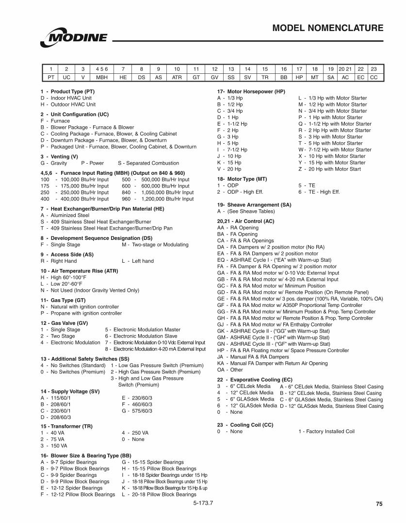
5-173.7
MODEL NOMENCLATURE
1 - Product Type (PT) D - Indoor HVAC Unit H - Outdoor HVAC Unit
2 - Unit Configuration (UC) F - Furnace B - Blower Package - Furnace & Blower C - Cooling Package - Furnace, Blower, & Cooling Cabinet D - Downturn Package - Furnace, Blower, & Downturn P - Packaged Unit - Furnace, Blower, Cooling Cabinet, & Downturn
3 - Venting (V) G - Gravity P - Power S - Separated Combustion
4,5,6 - Furnace Input Rating (MBH) (Output on 840 & 960) 100 - 100,000 Btu/Hr Input 500 - 500,000 Btu/Hr Input 175 - 175,000 Btu/Hr Input 600 - 600,000 Btu/Hr Input 250 - 250,000 Btu/Hr Input 840 - 1,050,000 Btu/Hr Input 400 - 400,000 Btu/Hr Input 960 - 1,200,000 Btu/Hr Input
7 - Heat Exchanger/Burner/Drip Pan Material (HE) A - Aluminized Steel S - 409 Stainless Steel Heat Exchanger/Burner T - 409 Stainless Steel Heat Exchanger/Burner/Drip Pan
8 - Development Sequence Designation (DS) F - Single Stage M - Two-stage or Modulating
9 - Access Side (AS)
10 - Air Temperature Rise (ATR) H - High 60°-100°F
N - Not Used (Indoor Gravity Vented Only)
11 - Gas Type (GT) N - Natural with ignition controller P - Propane with ignition controller
12 - Gas Valve (GV) 1 - Single Stage 5 - Electronic Modulation Master 2 - Two Stage 6 - Electronic Modulation Slave 4 - Electronic Modulation 7 - Electronic Modulation 0-10 Vdc External Input 8 - Electronic Modulation 4-20 mA External Input
13 - Additional Safety Switches (SS)
0 - No Switches (Premium) 2 - High Gas Pressure Switch (Premium)
Switch (Premium)14 - Supply Voltage (SV) A - 115/60/1 E - 230/60/3 B - 208/60/1 F - 460/60/3 C - 230/60/1 G - 575/60/3 D - 208/60/3
15 - Transformer (TR) 1 - 40 VA 4 - 250 VA 2 - 75 VA 0 - None 3 - 150 VA
16 - Blower Size & Bearing Type (BB) A - 9-7 Spider Bearings G - 15-15 Spider Bearings B - 9-7 Pillow Block Bearings H - 15-15 Pillow Block Bearings C - 9-9 Spider Bearings I - 18-18 Spider Bearings under 15 Hp D - 9-9 Pillow Block Bearings J - 18-18 Pillow Block Bearings under 15 Hp E - 12-12 Spider Bearings K - 18-18 Pillow Block Bearings for 15 Hp & up
17 - Motor Horsepower (HP)
B - 1/2 Hp M - 1/2 Hp with Motor Starter C - 3/4 Hp N - 3/4 Hp with Motor Starter D - 1 Hp P - 1 Hp with Motor Starter E - 1-1/2 Hp Q - 1-1/2 Hp with Motor Starter F - 2 Hp R - 2 Hp Hp with Motor Starter G - 3 Hp S - 3 Hp with Motor Starter H - 5 Hp T - 5 Hp with Motor Starter I - 7-1/2 Hp W - 7-1/2 Hp with Motor Starter J - 10 Hp X - 10 Hp with Motor Starter K - 15 Hp Y - 15 Hp with Motor Starter V - 20 Hp Z - 20 Hp with Motor Start
18 - Motor Type (MT) 1 - ODP 5 - TE 2 - ODP - High Eff. 6 - TE - High Eff. 19 - Sheave Arrangement (SA) A - (See Sheave Tables)
20,21 - Air Control (AC) AA - RA Opening BA - FA Opening CA - FA & RA Openings DA - FA Dampers w/ 2 position motor (No RA) EA - FA & RA Dampers w/ 2 position motor EQ - ASHRAE Cycle I - (“EA” with Warm-up Stat) FA - FA Damper & RA Opening w/ 2 position motor GA - FA & RA Mod motor w/ 0-10 Vdc External Input GB - FA & RA Mod motor w/ 4-20 mA External Input GC - FA & RA Mod motor w/ Minimum Position GD - FA & RA Mod motor w/ Remote Position (On Remote Panel) GE - FA & RA Mod motor w/ 3 pos. damper (100% RA, Variable, 100% OA) GF - FA & RA Mod motor w/ A350P Proportional Temp Controller GG - FA & RA Mod motor w/ Minimum Position & Prop. Temp Controller GH - FA & RA Mod motor w/ Remote Position & Prop. Temp Controller GJ - FA & RA Mod motor w/ FA Enthalpy Controller GK - ASHRAE Cycle II - (“GG” with Warm-up Stat) GM - ASHRAE Cycle II - (“GH” with Warm-up Stat) GN - ASHRAE Cycle III - (“GF” with Warm-up Stat) HP - FA & RA Floating motor w/ Space Pressure Controller JA - Manual FA & RA Dampers KA - Manual FA Damper with Return Air Opening OA - Other
22 - Evaporative Cooling (EC)
0 - None 23 - Cooling Coil (CC) 0 - None 1 - Factory Installed Coil
1 2 3 4 5 6 7 8 9 10 11 12 13 14 15 16 17 18 19 20 21 22 23
PT UC V MBH HE DS AS ATR GT GV SS SV TR BB HP MT SA AC EC CC
B - 1 C - 6" D - 12"
75

Products from Modine are designed to provide indoor air-comfort and ventilation solutions for residential, commercial, institutional and industrial applications. Whatever your heating, ventilating and air conditioning requirements, Modine has the product to satisfy your needs, including:
HVAC
• Unit Heaters:
– Gas
– Hydronic
– Electric
– Oil
• Ceiling Cassettes
• Duct Furnaces
• Hydronic Cabinet Unit Heaters, Fin Tube, Convectors
• Infrared Heaters
• Make-up Air Systems
• Unit Ventilators
Ventilation
• Packaged Rooftop Ventilation
School Products
• Vertical Packaged Classroom HVAC:
– DX Cooling/Heat Pump
– Water/Ground Source Heat Pump
– Horizontal/Vertical Unit Ventilators
Geothermal
• Water-to-Water
• Water-to-Air
• Combination Specific catalogs are available for each product. Catalogs 75-136 and 75-137 provide details on all Modine HVAC equipment.
Modine Manufacturing Company
1500 DeKoven AvenueRacine, Wisconsin 53403-2552Phone: 1.800.828.4328 (HEAT)www.modinehvac.com
© Modine Manufacturing Company 2013
The Modine brand has been the
industry standard since Arthur B.
Modine invented and patented
the first lightweight, suspended
hydronic unit heater in 1923.
No other manufacturer can
provide the combined application
flexibility, technical expertise and
fast delivery found at Modine.
Consult your local Modine
distributor for help in solving your
indoor air problems.