garrylaun proposed development and operation report
TRANSCRIPT

Garrylaun Proposed Development and Operation Report
The proposed development to be known as the ‘Garrylaun Mine/Project’ is for the recommencement
of underground mining of zinc and lead ore at the recently closed Galmoy Mine, from a number of
areas including the K2 and R Orebodies, and the G East Zone (Garrylaun). It is intended that the
works will initially be carried out within the existing mining footprint and use facilities as previously
constructed, a number of which will require refurbishment. As mentioned previously, zinc and lead
ore will be transported off-site to a licenced processing facility. As processing will take place off-site,
no tailings will be produced at the Site.
Initially ca. 25,000 tonnes of soils and rock will be removed from the portal and decline to allow
access into the mine workings. This material will be stockpiled on-site and used as future backfill
material (i.e. backfilling of the entrance decline and portal) following cessation of mining.
Mining operations will be highly mechanised, consisting of drilling, blasting and transporting of ore to a
crusher located on surface in the existing tepee. The equipment underground will include:
Multi-boom drilling rigs;
Load haul dump (LHD) units;
Mine haulage trucks;
Explosives loading vehicle; and
Roof bolting machine, shotcreting machine and other production and service equipment (e.g.
ancillary service and construction equipment, pump stations and electrical sub-stations).
Equipment servicing and repairs will be carried out on surface in a dedicated workshop, with routine
consumable supplies stored in an adjoining warehouse. Mobile maintenance vehicles equipped with a
crane, air compressor, welding machine and tools will carry out equipment repairs underground as
required.
The majority of the workings will be backfilled with a combination of backfill and cement-rockfill. The
backfill, together with pillars, rock bolts and shotcrete will provide ground support to the underground
workings.
The proposed extraction of ore will take place to a maximum depth of up to ca. 150 m bgl.
The design of the proposed development will continue to follow industry best practice and having
regard to its underground design will adhere to the Mines and Quarries Act 1965; the Guidelines to
the Safety, Health and Welfare at Work (Quarries) Regulations 2008 and all associated legislation.
The preferred design will include the following:
Re-opening of the existing portal and access decline;
Refurbishment of the underground water pumping system and surface water treatment facilities;
Refurbishment of the underground ventilation system, including ventilation shafts (one of which
will act as a secondary means of egress);
Refurbishment of the surface and underground electrical supply system;
Refurbishment of the existing backfill plant;
For
insp
ectio
n pur
pose
s only
.
Conse
nt of
copy
right
owne
r req
uired
for a
ny ot
her u
se.
EPA Export 07-06-2018:04:30:10
Refurbishment and upgrading of the underground backfill system;
Refurbishment of water treatment plant on surface including associated infrastructure and River
Goul discharge pipeline. A second point of discharge is also planned to the north of the Site;
Refurbishment of the tepee (i.e. the existing large covered storage area on surface where ore
from underground will be sized and loaded into trucks for road transport to an off-site facility for
processing); and
Refurbishment of associated facilities (including offices, storerooms, workshops and mine
change-house) and ancillary structures (both on surface and underground) for the safe running
of an operational underground mine.
The operating processes involved in the mining of the ore will include:
The extraction of ore from underground stopes and development drifts in a cyclical pattern using
drill, blast and haul methods;
Installation of ground support (including rock-bolts, cable-bolts, mesh and shotcrete);
The transportation of ore by dump truck to surface along the existing decline for crushing and
loading in the existing tepee; and
Road transportation of the ore to an off-site processing facility.
Existing landscaping (including screening berms) on the Site (and around ventilation shafts) will be
left intact to mitigate against noise and potential dust emissions from operations, as well as to offer
continued reduced visibility of the Site from the public road network and surrounding lands.
The existing Closure, Restoration & Aftercare Management Plan (CRAMP) for the Galmoy Mine will
be adapted, updated and agreed with the EPA for the recommencement of mining at the Site.
Employment & Operating Hours
An initial mining schedule has been developed for the Project using a JORC compliant mineral
resource estimate of ca. 2.3Mt, providing a potential life-of-mine (LOM) of ca. 10 to 12 years
(including a ramp-up and initial dewatering period of ca. 6 to 9 months), at a production rate of ca.
200,000 to 250,000 t/a.
Based on the LOM production estimate, the proposed development at the Site will generate ca. 35 to
40 direct jobs, including managerial/administrative, geological, mining, engineering, maintenance and
support personnel. Indirect Site employment (typically 10 to 15) will be generated in terms of contract
drillers, suppliers of products and services such as fuel, oil and machinery suppliers.
During the re-development and refurbishment phase of the project, on-site employment levels of up to
50 are anticipated over a ca. 6 month period.
The proposed operational hours for mining will be 2 x 12 hour shifts per day (with production shift
change-over starting at 07:00 hrs and 19:00 hrs, commencing at 07:00 hrs Monday and finishing at
19:00 hrs Saturday). The mine proposes to operate for 6 days per week with maintenance scheduled
on Sundays and Bank Holidays. There will be no blasting on Sundays. Mine dewatering and mine
backfilling operations will be continuous throughout the LOM.
For
insp
ectio
n pur
pose
s only
.
Conse
nt of
copy
right
owne
r req
uired
for a
ny ot
her u
se.
EPA Export 07-06-2018:04:30:10

Rationale for the Development
Shanoon Resources has applied to Kilkenny County Council and Laois County Council for planning
permission to recommence underground mining at the recently closed Galmoy Mine herein referred to
as the Garrylaun Mine/Project. The Kilkenny and Laois County Development Plans both support
mining activities, subject to sustainable development principles, as part of each county’s development
strategy. It is noted that the proposed development Site is located within an area of population
decline as noted in both County Development Plans. As such, the recommencement of the
development at the Site will create benefits to the local and national economies through the supply of
jobs directly related to the operation as well as indirect benefits through the use of local suppliers and
services. Based on the current economic and known mineral resources and mining reserves at the
Site, it is estimated that mining operations will be carried out over ca. 5 to 6 years from the
recommencement of operations. The recommencement of mining and parallel continued mineral
resource testing will identify any potential additional economic ore reserves that would extend the life
of the proposed project.
Zinc is a commodity that is only found in sufficient quantity (and quality) in a number of locations
around the globe and is currently in short supply in global terms, making the high quality zinc (and
lead) found at the Site of primary importance to the economy of the country as a whole.
Mining
As minerals can be worked only where they occur, the extraction of ore is geologically and
geographically isolated to the proposed development site and no alternatives are viable for the
location of the mine. The extraction methods chosen for the recommencement of mining at Garrylaun
will be the same as those previously used at the mine and will follow best practice, with material being
extracted from underground stopes and development drifts in a cyclical pattern using standard drill,
blast and haul methods. The ore will then be brought to the surface via dump trucks and crushed in
the existing tepee prior to transportation to an off-site processing facility.
Mine Development - Mining Sequence
All mining at Garrylaun will be by underground means. The mine design is based on a detailed
review, analyses and understanding of the previous mine design, mining methods, geotechnical
support and water management systems previously used at the mine and at the nearby Lisheen mine.
The resulting designs and controls proposed for the Project are in line with modern mine design
practice and environmental requirements.
Access to the orebodies will be by means of the existing mine portal and access declines/ tunnels.
Initially ca. 25,000 tonnes of soils and rock will be removed from the portal and decline to allow
access into the mine workings. This material will be stockpiled on-site and used as future backfill
material following cessation of mining.
As the water-table is drawn down, existing ground support will be reviewed, refurbished and upgraded
as required to ensure both a safe working environment over the LOM and long-term stability of the
underground workings following cessation of mining (and re-watering of the mine).
Water make from the underground workings will involve the development of separate ‘clean’ and
‘dirty’ water systems, where water will be segregated/collected underground prior to being pumped to
surface. Dirty water (or contact water) is water that has interacted with ore or the floor of the mine
workings, and acquired physical and chemical material that must be removed. Clean water is
collected directly via horizontal wells or fissures in the rock and does not contact ore. Dirty water will
be treated in the refurbished, pH controlled precipitation/clarification, Mine Water Treatment Plant
(MWTP). ‘Clean’ water will be used to provide additional attenuation for the treated ‘dirty’ water prior
to discharge.
For
insp
ectio
n pur
pose
s only
.
Conse
nt of
copy
right
owne
r req
uired
for a
ny ot
her u
se.
EPA Export 07-06-2018:04:30:10

As the water-table is further drawn down, electrical, water and ventilation systems will be installed,
including the refurbishment/installation of ventilation shafts (including a secondary means of egress),
pumping sumps/stations, electrical sub-stations, rescue stations and a backfill system.
Ground support for major development drives/areas will primarily be by rock bolts combined, when
required, with steel mesh, shotcrete and/or cable-bolts.
During pre-production development, test holes (‘probe holes’) will be driven ahead of all development
faces. The holes will be drilled to check for potential water inflows.
As part of the pre-production development, underground diamond drilling will be carried out to confirm
the location and outline of mineralization, to upgrade mineable resources into higher categories and to
obtain data for ground-support and optimise mine planning.
The K Zone will be accessed from the main G Orebody access as previous, with the K2 Zone being
accessed via the main K Zone access drive. The G East area will be accessed by means of an
existing access tunnel/drift from the main G Orebody access drive, with the R Zone being accessed
from the CW Orebody as previously undertaken (Figure 1). In order to achieve the design
requirement of ca. 200,000 to 250,000 t/a at an average resource grade for efficient processing, it is
proposed to mine ore concurrently from a number of different areas throughout the mine.
Figure 1: Underground workings showing areas to be mined
Mining Design - Mining Methods
The proposed mining methods for the recovery of ore at Garrylaun are:
Longhole Open Stoping (G East and R);
Longhole Pillar Retreat (G East and R);
Drift and Fill (K2); and
Room & Pillar (G East, K, K2 and extensions to known ore).
For
insp
ectio
n pur
pose
s only
.
Conse
nt of
copy
right
owne
r req
uired
for a
ny ot
her u
se.
EPA Export 07-06-2018:04:30:10

A review of the mining methods and ground stability issues associated with the recommencement of
mining at Galmoy was carried out by Avoca Geotech Limited.
Longhole Open Stoping
In the areas of thickest ore, typically greater than 15 m, open stoping with backfill is proposed. This
method involves the mining of drifts along the upper, hangingwall contact and lower, footwall contacts.
The upper drift is widened to 10 m and rows of vertical holes then drilled down from the top drift to the
footwall contact or bottom drift. A free face is created at the end of the stope and the rows of holes
then blasted in retreat. Mucking of the broken ore takes place by load-haul-dump (LHD) machines
from a "drawpoint" at the lower level, with the final ore being cleaned using remote controlled LHDs.
Details of this method are presented in Figure 2.
This method is carried out in a primary/secondary sequence with backfill being placed in primary
stopes prior to mining of the adjacent secondary stopes.
Figure 2: Longhole open stoping
Longhole Pillar Retreat
Where the ore is between 8 and 15 m thick, a variation of the open stoping method will be employed
known as bench stoping. In this method an upper hangingwall drift only is mined. The ore is again
extracted by vertical row of holes drilled down from the upper drift, but in this method the holes are
drilled ‘blind’. The holes are sub-drilled to ensure all the ore is recovered. The broken ore is loaded
by remote controlled LHD machines from a lower access as presented in Figure 2.
Mining is again carried out using a primary/secondary sequence, with backfilling taking place after
each phase.
Drift and Fill
Where the ore is <less than 8 m thick and rock quality allows, the drift and fill mining method will be
used. Figure 3 presents the stages of this method.
For
insp
ectio
n pur
pose
s only
.
Conse
nt of
copy
right
owne
r req
uired
for a
ny ot
her u
se.
EPA Export 07-06-2018:04:30:10

A series of parallel primary drifts, 5 m wide, are mined down dip from an access drive. On completion
of the primary drives they are backfilled. Following curing of the backfill the 10 m wide temporary
pillars between the primary drives are mined as secondary drifts. A 4 m wide drive is initially mined
down the centre of the secondary pillar and the remaining ore then ‘slashed’ on retreat to the backfill.
As each secondary drive is completed it is backfilled resulting in the whole stope block being
backfilled.
Drift and fill is a commonly used mining method in higher value orebodies, and the dimensions
selected for Galmoy are such that flexibility and changing to conventional room and pillar can be
easily undertaken.
Figure 3: Drift and fill mining method
Room and Pillar Mining
Room and pillar mining (stoping) with integrated backfill will be the primary method used for mining
the additional mineral resources in parts of G East, K and K2 zones. In accordance with good
engineering practice, the mining methods will be continuously evaluated and may, on the basis of
additional geotechnical information and operating experience, be modified without compromising the
objectives of operating safety, control of subsidence, economics, or minimizing environmental
impacts.
The room and pillar mining method will be used where the ore thickness is < 8 m. Where the ore
thickness is 5 m or less the rooms will typically be limited to 10 m wide and the pillars will be 5 x 5 m.
Where the ore is > 5 m the pillar dimension will be based on an assessment of the rock quality and
best practice geotechnical criteria. The various stages in room and pillar mining are shown in Figure
4.
Following the extraction of the ore from a room and pillar mining panel, the area will be backfilled, with
the remaining pillars extracted upon retreat depending on ground conditions.
The following technical considerations have been applied in the selection of the proposed mining
methods:
Where ore is gently dipping and relatively thin (K, K2, parts of G East), the room and pillar, and
drift and fill methods will be integrated with backfill to provide maximum support and long-term
rockmass stability with respect to possible subsidence;
For
insp
ectio
n pur
pose
s only
.
Conse
nt of
copy
right
owne
r req
uired
for a
ny ot
her u
se.
EPA Export 07-06-2018:04:30:10

Where ore is relatively thick (parts of G East and R), the long hole mining methods will be
integrated with backfill to provide maximum support and long-term rockmass stability with
respect to possible subsidence;
The mining methods proposed are easily mechanized, and have previously been used
extensively at Galmoy, Lisheen and Tara to successfully extract ore;
Considerable experience exists within the vicinity of Galmoy (and Lisheen) in terms of
experience specific to the mining methods proposed;
The mining methods proposed are flexible and can be matched to varying ground conditions by
varying room dimensions, pillar widths and ground support techniques;
Previous experience at Galmoy (and Lisheen) proves that the proposed mining methods can
been used safely and efficiently; and
Control over surface subsidence has been demonstrated by the previous methods of extraction
and ground support employed at Galmoy and neighbouring Lisheen Mine.
Figure 4: Room and pillar mining method
Mining from multiple areas within the mine will provide a blended, consistent and optimised feed (zinc
and lead grade) for processing and will also provide flexibility and allow for varying rates of extraction
and backfilling.
2.1.1 Blasting
Production and development blasts will be designed to ensure vibration levels (peak particle velocity
(ppv) expressed as maximum peak particle velocity, in any plane, measured at foundation level) at
For
insp
ectio
n pur
pose
s only
.
Conse
nt of
copy
right
owne
r req
uired
for a
ny ot
her u
se.
EPA Export 07-06-2018:04:30:10

the nearest private residence will not exceed the previous IPC Licence (P0517-02) requirements of 8
mm/sec for day time (08.00 hrs to 22.00 hrs) and 4 mm/sec for night time (22.00 hrs to 08.00 hrs).
Previous operating experience at the Site has shown that resultant peak particle velocities, blast
noise, and air overpressure complied with EPA requirements. It is expected that no new impact(s) will
arise from the proposed recommencement of mining at Galmoy.
Monitoring of all blasts will be carried out as part of the company’s obligation under its IPC Licence
(once granted) using permanent vibration monitors located at the monitoring stations. The location of
these monitoring stations is chosen based on their proximity to sensitive residences.
Explosives Storage
No explosive storage facility (Magazine or Reserve Station), on surface or underground will be utilised
for the Project.
Mine Ventilation
Ventilation air will be drawn down the main access decline by means of ventilation fans located at the
base of each ventilation shaft. Air will be directed, as required, throughout the underground workings
by a combination of area ventilation fans, ventilation bulkheads, doors, brattices and ventilation
ducting. Exhaust air will be upcast by means of the R, K and G ventilation shafts (Figure 5). Shafts
vary in length from ca. 50 to 130 m and are 3.5 m x 3.5 m in cross-section (Figure 6).
Figure 5: Location of ventilation shafts
Control of the main ventilation fans will be located close to the fans, with parallel controls at the
surface within the surface housings. Back-up fans will also be provided at the surface to permit safe
For
insp
ectio
n pur
pose
s only
.
Conse
nt of
copy
right
owne
r req
uired
for a
ny ot
her u
se.
EPA Export 07-06-2018:04:30:10

evacuation of the mine via the ventilation raises. A permanent manway will be installed on each
ventilation raise with an emergency exit door in the surface breakthrough housing. These will be
secured against any unauthorised entrance into the mine workings.
By redirecting the air flows in the mine, the combined quantity of air exhausted from the mine’s
ventilation shafts will not exceed 210 m3/sec, the quantity stated in Schedule 1(i) Emissions to
Atmosphere of the previous IPC Licence for the Site.
Dust concentrations in the ventilation system exhaust will be very low and it is anticipated that a level
of 0.5 mg/m3 will not be exceeded. For this reason, no dust suppression measures will be
incorporated into the mine ventilation exhaust.
Figure 6: Cross-section through a typical ventilation shaft
Ground Stability and Support
An extensive network of subsidence monitoring stations was put in place by the previous mine
operators and will be revised and updated in consultation with the relevant authorities and
landowners. A new baseline set of the surface levelling measurements will be taken prior to
dewatering the mine, with additional stations being put in place over the K2 and Garrylaun Zones.
The trends from the subsidence survey data over the life of the mine indicate that there is no
subsidence on surface due to changes in the global stability of the mine workings within the
orebodies.
Geotechnical studies, coupled with the mining methods, ground support and water management
systems previously used at Galmoy Mine, enabled a robust review of the expected ground conditions
to be undertaken for the proposed development by Avoca Geotech Ltd. Key findings from this review
are:
The overall stability of the Galmoy Mine at closure was good and that all the large stopes had
been backfilled except for the R Access Pillar (RAP) which is located at depth in very good
ground;
For
insp
ectio
n pur
pose
s only
.
Conse
nt of
copy
right
owne
r req
uired
for a
ny ot
her u
se.
EPA Export 07-06-2018:04:30:10

The adherence to a robust ‘Pillar Management System and Underground Failure Prevention
Plan’ developed with Golder ensured a safe closure of the mine maintaining its stability and
integrity;
The extensive database of face-mapping sheets available from the mine (recording both geology
and ground conditions) provide valuable information on the behaviour of all rock types
encountered, in particular the massive sulphide ore and should be utilised when re-entering mine
workings and planning for ore extraction;
As dewatering of the mine will impact both the characteristics of the ground and installed
support, a rigorous examination of all re-exposed ground will be carried out by systematic testing
of previous ground support systems and where necessary scaling or the application of additional
support;
Any open features encountered should be sealed with shotcrete leaving short lengths of water
pipe in the opening to prevent water pressure build-up and provide drainage;
Any loose shotcrete should be removed and replaced with synthetic fibre shotcrete to maximize
support;
Mining alongside any backfilled area will have to be undertaken with caution, with areas probe
drilled to check for backfill integrity prior to mining; and
A new baseline set of surface levelling measurements (subsidence) should be taken prior to
dewatering of the mine. In addition, it is recommended that a remote sensing survey using
Interferometric Synthetic Aperture Radar (InSAR) from satellites be carried-out (similar to that
undertaken at the Lisheen Mine).
The selection of the correct support category will be chosen by the mine planning engineer on
information from geology, mine operational staff, as well as a thorough assessment of the previously
installed ground support.
The ore zone and immediate hangingwall rocks at Galmoy have been geotechnically evaluated as
being ‘fair’ to ‘very good’ in strength using the universally accepted Q rock quality rating system. As
the mining depth at Galmoy is less typically < 100 m below surface a low stress environment exists
relating to the mine workings.
Ground support methods that have been used in the mine access ramps are a combination of
rockbolting, meshing, shotcreting, and steel arches.
Within the mine workings sub-vertical weathered joints and fissures have been exposed, ranging in
width from a few centimetres up to 8 m. Overbreak into the roof at these features has typically not
been excessive. Usually rockbolts and shotcrete are sufficient to stabilise and support these features,
and in no cases have they propagated upwards towards surface or laterally in any manner.
Occasionally steel arches were used to supplement the above support elements. Some of these
joints and fissures are water bearing when first intersected, but water inflow from them generally
decreases rapidly or dries up completely as mining progresses past the joints and fissures.
Figure 7 shows general stoping/mining conditions at Galmoy (prior to backfilling), reflecting the very
good stability of the mined rooms and pillars.
Figure 8 shows the ability to completely fill mined out stopes/areas with backfill which minimises
rockmass movement.
For
insp
ectio
n pur
pose
s only
.
Conse
nt of
copy
right
owne
r req
uired
for a
ny ot
her u
se.
EPA Export 07-06-2018:04:30:10

Figure 7: Typical rooms and pillars, Galmoy Mine prior to backfilling. The competent rock conditions shown are an example of good rockmass conditions expected in the K2, K and R zones.
For
insp
ectio
n pur
pose
s only
.
Conse
nt of
copy
right
owne
r req
uired
for a
ny ot
her u
se.
EPA Export 07-06-2018:04:30:10

Figure 8: Close-up of backfill in the G Stope, CW Orebody, showing the ability to fill the mined void providing tight contact between the backfill and roof of the stope
Backfilling
The majority of mined out areas in the Garrylaun Zone will be backfilled with placed support material.
Cement will be added to the backfill to allow pillar extraction during mining operations. This will
provide a low to medium (250-500 Kpa) strength backfill that is quick draining, free standing and has
low shrinkage properties. The sequencing of mining and backfilling will be critical to ensure that any
unsupported mined span is backfilled as tight and as soon as possible, with extra care taken to
ensure that all voids on top of stopes are filled with ‘topping up’ by drilling extra filling holes when
required.
In addition, it is proposed to use Waste-Rock Packing and/or Cemented Rockfill (CRF) in the K, K2
and R where the ore tends to be thinner (< 8 m) and there is greater rockmass stability.
The augmentation of cement with engineered concrete additives is now a proven technology in mine
backfilling. The proportion of cement to be replaced will be determined by laboratory and full-scale
tests designed to maintain the structural integrity of the backfill. Backfill will be transported
underground where it will be pumped into the mined out voids.
Parameters to be used for the fill material at Garrylaun are targets that are standard in the mining
industry. Full-scale tests will determine the fill strength and cement addition required to suit a
cementitious type fill. In addition to laboratory tests on the backfill, instrumentation such as extension
meters, strain gauges, pressure gauges, water content meters, etc. will be used to measure the
effectiveness of fill in place.
Each longhole stope will be surveyed with a cavity monitoring system (CMS) to reconcile the backfill
volume placement.
Mine Dewatering
The mine will be dewatered by a combination of the drilling of specific (temporary) dewatering wells in
close proximity to the Access Decline, refurbishment of surface dewatering well (PW5A), pumping
from ventilation shafts (where appropriate) and in-mine dewatering (from sumps/pump station located
in the main access drives) (Figure 9). In-mine dewatering will be of two types:
‘Clean’ water drawn from horizontal / inclined wells and captured locally from fissures and joints
within the mine workings; and
‘Dirty’ water bypassing the surface and in-mine wells that collects in the mine sumps.
For
insp
ectio
n pur
pose
s only
.
Conse
nt of
copy
right
owne
r req
uired
for a
ny ot
her u
se.
EPA Export 07-06-2018:04:30:10

Figure 9: Mine dewatering wells
The primary purpose of the chosen mine dewatering method, incorporating surface and in-mine wells,
is to remove from the immediate proximity groundwater that has not come into contact with the mine
workings. In this manner, the majority of the water generated by the mine dewatering system will be
clean and will require the minimum of treatment prior to its discharge to the environment. Local
control methods will be used to ensure that total suspended solids are minimised from water that is
present on the mining horizon.
Following the shutdown of the final remaining pumps in CW and R orebodies on 11 March 2013, the
water-table at Galmoy Mine started to recover. The original predicted time for full recovery was 18
months. However, pre-mining (baseline groundwater) conditions became re-established in March
2014, about 12 months after dewatering ceased. The recovery time was quicker than expected due
to the extremely high rainfall and groundwater recharge that occurred in January and February 2014,
with local baseflow (groundwater discharge) to the Glasha Stream and its tributaries (to the north)
becoming re-established.
Because the full area of the Galmoy ‘block’ is hydrologically interconnected, dewatering of the full
block will be required, regardless of the footprint of future mining. The historical dewatering rate for
the Galmoy block was mostly within the range ca. 10,000 m3/d to 14,500 m
3/d (Figure 10). Once the
initial groundwater storage within the block has been removed, a similar dewatering rate can be
expected for the planned recommencement of mining.
For
insp
ectio
n pur
pose
s only
.
Conse
nt of
copy
right
owne
r req
uired
for a
ny ot
her u
se.
EPA Export 07-06-2018:04:30:10
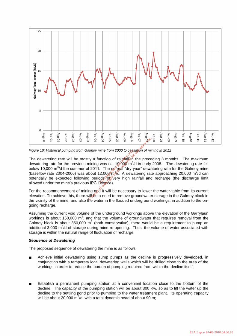
Figure 10: Historical pumping from Galmoy mine from 2000 to cessation of mining in 2012
The dewatering rate will be mostly a function of rainfall in the preceding 3 months. The maximum
dewatering rate for the previous mining was ca. 19,000 m3/d in early 2008. The dewatering rate fell
below 10,000 m3/d the summer of 2011. The normal “dry-year” dewatering rate for the Galmoy mine
(baseflow rate 2004-2006) was about 12,000 m3/d. A dewatering rate approaching 20,000 m
3/d can
potentially be expected following periods of very high rainfall and recharge (the discharge limit
allowed under the mine’s previous IPC Licence).
For the recommencement of mining and it will be necessary to lower the water-table from its current
elevation. To achieve this, there will be a need to remove groundwater storage in the Galmoy block in
the vicinity of the mine, and also the water in the flooded underground workings, in addition to the on-
going recharge.
Assuming the current void volume of the underground workings above the elevation of the Garrylaun
workings is about 150,000 m3, and that the volume of groundwater that requires removal from the
Galmoy block is about 350,000 m3 (both conservative), there would be a requirement to pump an
additional 3,000 m3/d of storage during mine re-opening. Thus, the volume of water associated with
storage is within the natural range of fluctuation of recharge.
Sequence of Dewatering
The proposed sequence of dewatering the mine is as follows:
Achieve initial dewatering using sump pumps as the decline is progressively developed, in
conjunction with a temporary local dewatering wells which will be drilled close to the area of the
workings in order to reduce the burden of pumping required from within the decline itself;
Establish a permanent pumping station at a convenient location close to the bottom of the
decline. The capacity of the pumping station will be about 300 Kw, so as to lift the water up the
decline to the settling pond prior to pumping to the water treatment plant. Its operating capacity
will be about 20,000 m3/d, with a total dynamic head of about 90 m;
For
insp
ectio
n pur
pose
s only
.
Conse
nt of
copy
right
owne
r req
uired
for a
ny ot
her u
se.
EPA Export 07-06-2018:04:30:10
Establish both a ‘clean’ and ‘dirty’ water line to the respective holding ponds on surface;
Establish staged collector sumps as the workings are gradually extended outwards. The collector
sumps would have low head transfer pumps to route the water to the permanent pumping
station. It is likely that initial development will be towards G-North and G-South ventilation shafts,
to allow a ventilation system to be set up as soon as possible; and
Adopt a program of grouting for the K2 orebody.
The planned extraction of ore from the K2 orebody will extend the existing workings to the west of the
K orebody. In order to ensure that drawdown in the area of the Replacement Water Supply Scheme
(RWSS) wells remains low, and consistent with the previous period of mining activity, any new
potential inflow zones will be grouted, to prevent the water from entering the workings. As the
workings are extended to the west, cover drilling will be undertaken to identify the hydrogeological
conditions prior to mining. If fracture zones that have the potential to carry groundwater into the
workings are encountered, the fracture zones will be pressure grouted from underground, prior to
advancing the workings.
The development proposes to re-commission the previous underground pumps and re-use the
existing pipelines, holding ponds, water treatment plant and outfall pipeline.
Predicted Drawdown
The magnitude of drawdown in existing wells within the Galmoy block is expected to be similar to the
drawdown already observed during the previous period of mining.
The previous period of mining impacted a number of the two bedrock springs within the immediate
area of the mine. Both springs occur at a topographic elevation of about 130 m OD, and both formed
part of the natural groundwater discharge system for the Galmoy block. It is predicted that both of
these springs will also dry up during the proposed mining. As dewatering progresses, the water-table
will drop below the invert level of the springs, so the groundwater discharge and spring flow will
cease.
There were no other observed impacts to springs or bogs during the previous period of mining. There
were no changes to Whiteswall Bog or to other wetland areas to the north and east of the mine. No
impacts to other springs, wetlands or bogs are expected as a result of the proposed future mining
operation.
The existing Group Scheme (RWSS) water supply wells WW1A and WW2B were operated
throughout the entire period of previous mining. There was some drawdown due to the previous
dewatering, but it did not significantly affect the operation of the wells. The same condition would be
expected for the recommencement of mining because the future drawdown area and drawdown
magnitude will be the same as for previous mining.
Groundwater monitoring during the previous period of mine operations and closure showed that the
groundwater system in the area of the RWSS wells was separated from the immediate mine area by a
hydrogeological boundary (a north-northwest trending fault/fracture zone), causing the groundwater
flow to be compartmentalised. Thus, no significant changes to the operation of the RWSS wells are
expected in the future. Although mining of the K2 orebody is proposed as part of the future mine plan,
cover grouting is planned in this area to prevent additional groundwater inflows, and thereby prevent
any additional impacts to the groundwater system. The planned program of cover grouting will isolate
underground mining activities from groundwater in the surrounding bedrock.
The two RWSS wells (WW1A and WW2B) are upgradient from the mine workings, both by
approximately 500 m. Monitoring data for both wells through 2017 demonstrate that all chemical
parameters continue to be stable and to comply with the Irish drinking water standards. No changes
to water quality in the RWSS wells are expected as a result of the planning mining operation.
For
insp
ectio
n pur
pose
s only
.
Conse
nt of
copy
right
owne
r req
uired
for a
ny ot
her u
se.
EPA Export 07-06-2018:04:30:10

Control of Acid Rock Drainage
Acid Rock Drainage (ARD) refers to the natural oxidation and hydrolysis to acidic sulphate solutions
that can occur to sulphide minerals when exposed to air and water. These acidic solutions are rapidly
neutralised by reaction with carbonate minerals, and in situations where the carbonate minerals are in
excess, there will be no net production of acidic water. The host rock of the Galmoy mineralisation is
primarily calcium and magnesium carbonate (limestone) both of which have a high neutralisation
potential. Even if acid is generated in microenvironments around sulphide grains it will rapidly be
neutralized by calcium and magnesium carbonate to generate pH neutral conditions. This is the
situation that exists in most of the Galmoy orebodies.
Sampling to date has shown that no Acid Rock Drainage has been produced on-site at Galmoy.
Environmental Protection Measures
Comprehensive environmental protection measures have been incorporated into the proposed
development in-line with what went previously and in-line with Shanoon’s Environmental Policy,
including:
Installation of crusher in the tepee to eliminate noise and dust impact at surface;
Transport of ore to surface by truck to eliminate the visual impact of a conveyor and head frame;
Blasting arranged and designed to ensure acceptable vibration limits at residences in the vicinity
of the mine area;
Mining methods selected to assure no significant surface subsidence; and
‘Clean’ and ‘dirty’ mine water separation underground designed to minimize the treatment of
water prior to discharge to the River Goul and the Glasha Stream.
Dirty water pumped from the mine will first passed through a tilting plate (Lamella) separator to
remove the majority of the suspended solids. This treatment unit consists of mixing, flocculation
and solids separation. Polyelectrolyte is added at the plant inlet followed by flash mixing,
flocculation and then solids separation in the lamella separator. At the inlet the incoming flow is
split between two parallel units using splitting weirs. The clarified water overflows from the
lamella tank into a series of launders at the surface. The separated solids fall to the bottom of
the unit and are removed through sludge pumps. This sludge will be periodically removed from
the unit and reused underground as backfill material.
The clarified water flows from the lamella unit into the second stage of treatment which
consists of reagent addition and mixing followed by clarification in a reactor clarifier. The
reagents, which can be added at this stage, include polyelectrolyte and lime.
The purpose of this stage of the treatment plant is to remove residual suspended matter and
to remove dissolved metals by pH adjustment using lime and precipitation in the clarifier as
hydroxides.
pH monitors are installed in the mixing tank and clarifier with a control loop to regulate the
addition by lime. The system operates within pre-determined set points which can be
adjusted to achieve the optimum pH for metal hydroxide formation. The output from the pH
probes and the status of all important aspects of the treatment plant will report continuously
to the environmental DCS workstations. In the event of a malfunction or any parameter
drifting outside of its pre-determined operating range an alarm will register on the
workstations and alert the operator to the problem. The control centre will be manned around
the clock. In this way the system is monitored on a continuous basis.
The clarified water is collected in radiating launders and discharged into a transfer tank from
where it is pumped to the Water Treatment Pond on-site prior to discharge to the River Goul.
For
insp
ectio
n pur
pose
s only
.
Conse
nt of
copy
right
owne
r req
uired
for a
ny ot
her u
se.
EPA Export 07-06-2018:04:30:10

An existing bunded fuel tank for central heating to the Administrative Building (Planning Drawing
No. 11) will be retained, with a new bunded fuel tank replacing the one that exists to the rear of
the Change-house.
Laboratory facilities will include an environmental laboratory, within the administrative building.
All domestic sewage arising on the site will be piped to a proprietary effluent treatment system
(Appendix 2.1). The treated discharge will be pumped into the Water Treatment Pond on site as
was previously undertaken. Typically, this system produces an effluent with a B.O.D. and
suspended solids level of less than 10 mg/l.
The six existing ventilation raises will be refurbished as part of the proposed development.
Where the ventilation raises reach the surface, a surface housing of sheet metal construction on
a metal frame (an evasse) will be erected, approximately 5.5 m by 4 m by 5.5 m high. Steel
doors will be set in the wall of this construction for access and emergency escape purposes.
The installation will be surrounded by a 2.5 m high security fence. Existing screen planting and
landscaping will be maintained or enhanced to minimise the visual impact of the surface housing.
No unauthorised access to the mine through these installations will be permitted.
Hazardous and non-hazardous waste generated by the operation will be deposited into specially
designed skips located at prescribed locations on the Plant Site. These will be collected for off-
site disposal at a licenced waste facility by a private contractor. Packaging for reagents, which
cannot be recycled, will be disposed of through a licenced waste disposal contractor who will
collect all such materials on a regular basis for off-site destruction. Non-reusable metal reagent
drums will be thoroughly cleansed on site, with washings being passed through the water
treatment system. Washed drums will be crushed and then disposed of as scrap metal. A waste
oil storage tank (ca. 20 m3) will be provided adjacent to the maintenance workshops for
collection and storage of used engine oil and oil products removed from oil/water separators.
This will be regularly collected for recycling by a licenced oil recycling operator.
Emergency plans will be developed by the Company to deal with serious safety incidents that
may arise within the operation.
For
insp
ectio
n pur
pose
s only
.
Conse
nt of
copy
right
owne
r req
uired
for a
ny ot
her u
se.
EPA Export 07-06-2018:04:30:11
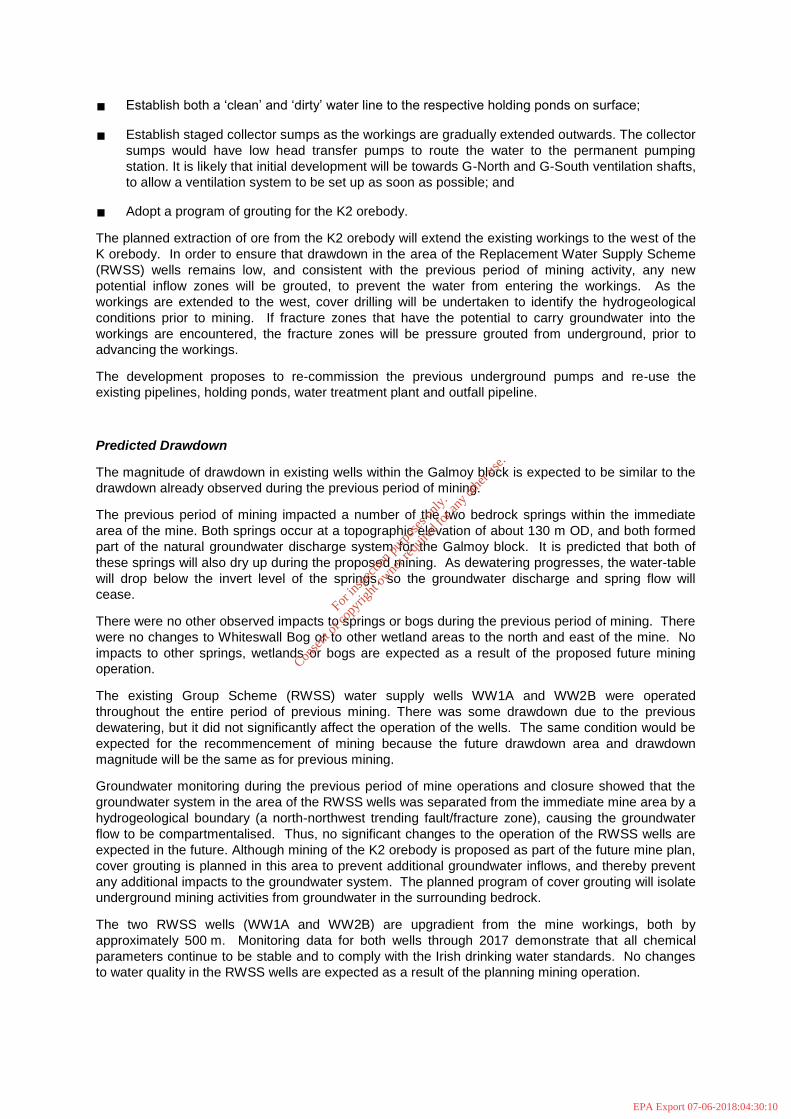
Figure 11: Plant Site layout showing main infrastructure
For
insp
ectio
n pur
pose
s only
.
Conse
nt of
copy
right
owne
r req
uired
for a
ny ot
her u
se.
EPA Export 07-06-2018:04:30:11

Mine Closure
Legislation and Best Contemporary Practice require that a Mine Closure Plan (MCP) be prepared to
facilitate a controlled exit from any redundant mine in order to minimise the long-term environmental
liabilities. Adequate financial provision must be made for closure and the plan should incorporate
both physical rehabilitation and socio-economic considerations. The MCP must be regularly
reviewed and updated to meet new and revised regulations to ensure that an assessment of the
environmental liabilities have sufficient financial security to address these liabilities. The objective
of the MCP is to ensure that, after mining operations cease, the site does not present a hazard to
public health and safety or an environmental liability as a result of physical and chemical deterioration.
The mine’s previous operator, Galmoy Mines Ltd. produced a Mine Closure Plan (MCP) in line with
legislative requirements linked to the original planning permission granted in 1994 and the IPPC
Licence granted in 2002. A number of revisions were undertaken throughout the life-of-mine to reflect
changes in legislative requirements, operational circumstances and new technologies.
In 2008, Galmoy Mines Ltd. entered into advanced discussions with all stakeholders (EPA, DCENR,
KCC, Laois County Council (LCC), and South Regional Fisheries Board (SRFB)) to agree a planned
and comprehensive closure of the mine by means of the non-statutory Mine Closure Committee. The
criteria for successful rehabilitation were clearly outlined and were achieved through the Closure,
Restoration and Aftercare Management Plan (CRAMP). Active and Passive Care periods have been
completed with a clearly defined Monitoring Programme. Provision is being finalized by the current
owner of the Site (including the TMF) for the longer term aftercare.
The overall objective of Mine Closure is to achieve stable physical and chemical environmental
conditions and a land use compatible with the adjacent countryside. Specifically, it is Shanoon’s
intention that:
The underground workings and infrastructure will be decommissioned (ensuring long-term mine
stability);
Most plant and equipment will be removed from underground for scrap or resale. Any fixed
plant left underground will be drained of oils and cleaned to remove any hydrocarbon
residues. All services will be removed from the length of the decline and it will be sealed off
and filled with clean demolition rubble.
The major part of the Plant Site will be decommissioned and rehabilitated to a state where the
site can be developed and used for other enterprises by;
Cleaning and removing plant; and
Removal of certain infrastructure/services.
The mine portal will be sealed and backfilled;
The ventilation shafts will be backfilled and sealed;
Waste materials and residues will be removed off-site to a licenced facility; and
Monitoring will be undertaken on a phased basis (i.e. active and passive, leading to long-term
aftercare monitoring and securing of a mine closure certificate).
Figure 12 presents the proposed restoration plan for the Site once mining has ceased and the water-
table has rebounded.
The existing Closure, Restoration & Aftercare Management Plan (CRAMP) for the Galmoy Mine will
be adapted, updated and agreed with the EPA for the recommencement of mining at the Site.
For
insp
ectio
n pur
pose
s only
.
Conse
nt of
copy
right
owne
r req
uired
for a
ny ot
her u
se.
EPA Export 07-06-2018:04:30:11

Figure12: Proposed restoration plan for the mine Plant Site
For
insp
ectio
n pur
pose
s only
.
Conse
nt of
copy
right
owne
r req
uired
for a
ny ot
her u
se.
EPA Export 07-06-2018:04:30:11

Monitoring
An Environmental Management System (EMS) for the Site will be maintained and updated, with
regular environmental monitoring of noise, vibration, dust, water quality and water discharge to ensure
that they remain within permitted levels for the life of the mine. Figure 13 presents the location of the
proposed monitoring points for the development.
For
insp
ectio
n pur
pose
s only
.
Conse
nt of
copy
right
owne
r req
uired
for a
ny ot
her u
se.
EPA Export 07-06-2018:04:30:11

Figure 13: Proposed monitoring locations
For
insp
ectio
n pur
pose
s only
.
Conse
nt of
copy
right
owne
r req
uired
for a
ny ot
her u
se.
EPA Export 07-06-2018:04:30:11

The environmental management and monitoring requirements defined in the Licence will be fully
incorporated into the EMS.
Any complaints received will be logged in a Complaints Register which will be maintained on site as
part of the EMS.
A comprehensive monitoring system will be put in place to provide monitoring of environmental
parameters. The system will provide monitoring of:
Dirty mine water volumes pumped for treatment;
Status of the mine water treatment plant;
Quality of the Water Treatment Pond, Groundwater Conditioning Pond and the discharge with
respect to pH; conductivity; dissolved oxygen and temperature;
Discharge rates from each of the ponds and the volumes pumped to the River Goul; and
Quality (including composite sampling) and flow of the River Goul both upstream and
downstream of the discharge point with respect to pH; conductivity, dissolved oxygen and
temperature.
In addition to the monitoring data display and data storage functions the system will provide a control
of all equipment associated with water flows, water treatment and discharges.
There are safety features built into the system for environmental protection purposes. The four
parameters, pH, conductivity, dissolved oxygen and temperature, which are continuously monitored in
the discharge have pre-programmed upper and lower limits. If the quality of the discharge drifts
outside of these limits an alarm will register to alert the operator. During normal working hours the
alarm will be responded to by environmental staff. At all other times the alarm will be responded to by
security staff. In this way 24-hour coverage will be is provided.
An environmental laboratory will be provided in the administration building and will be equipped to
meet all of the routine monitoring requirements at the mine and will utilise standard analytical
techniques.
For
insp
ectio
n pur
pose
s only
.
Conse
nt of
copy
right
owne
r req
uired
for a
ny ot
her u
se.
EPA Export 07-06-2018:04:30:11