garrison project - lake sakakawea oil and gas management
TRANSCRIPT

Garrison Project Riverdale, North Dakota Omaha District Army Corps of Engineers U.S. Department of Defense
Garrison Project - Lake Sakakawea Oil and Gas Management Plan North Dakota
December 2013

This space left blank intentionally.
TABLE OF CONTENTS 1.0 Introduction ............................................................................................................................ 1
2.0 Scope and Objectives of this Plan ......................................................................................... 2
3.0 Background ............................................................................................................................ 2
3.1 Previous Exploration ............................................................................................................ 2
3.1.1 Oil .................................................................................................................................. 2
3.1.2 Natural Gas .................................................................................................................... 3
3.1.3 Oil and Gas Chronology on the Garrison Project .......................................................... 3
3.1.4 Oil and Gas Pipeline Chronology on the Garrison Project ............................................ 8
3.2 Mineral Ownership ............................................................................................................. 14
4.0 Management Vision and Direction ..................................................................................... 14
4.1 Conformance with Corps Management Plans .................................................................... 14
4.2 Management Vision ........................................................................................................... 21
5.0 Roles and Responsibilities ................................................................................................... 21
5.1 Authorities .......................................................................................................................... 21
5.1.1 Federally-Owned Minerals on the Garrison Project .................................................... 21
5.1.2 State or Privately-Owned Minerals Underlying Garrison Project Managed Surface Acreage ................................................................................................................................. 22
5.1.3 State or Privately-Owned Minerals Accessed From State or Privately-owned Land . 23
5.2 Roles and Responsibilities ................................................................................................. 23
5.3 Implementation ................................................................................................................... 27
6.0 Administrative Process ........................................................................................................ 28
6.1 Legislation Framework ...................................................................................................... 28
6.1.1 Corps Regulations ....................................................................................................... 28
6.1.2 Excepted Mineral Rights ............................................................................................. 28
6.1.3 Navigable Waters ........................................................................................................ 29
6.2 Other Laws Relating to Oil and Gas Activity on Corps-Managed Lands .......................... 29
6.2.1 National Environmental Policy Act (NEPA) .............................................................. 29
6.2.2 National Historic Preservation Act (NHPA) of 1966, as amended ............................. 30
6.2.3 Archaeological Resources Protection Act of 1979 ...................................................... 30
6.2.4 Migratory Bird Treaty Act and Migratory Bird Conservation Act ............................. 30
6.2.5 Endangered Species Act .............................................................................................. 30
6.2.6 Fish and Wildlife Coordination Act ............................................................................ 30
6.3 Other Federal Regulations and Considerations .................................................................. 31
6.4 State Regulations and Rules ............................................................................................... 31
6.4.1 North Dakota Industrial Commission’s Oil and Gas Division .................................... 31
6.4.2 North Dakota Department of Health ........................................................................... 31
6.4.3 Other State Regulations and Rules .............................................................................. 32
7.0 Description of Oil and Gas Development Activity ............................................................ 32
7.1 Description of Mineral Resources ...................................................................................... 32
7.1.1 Oil Resources............................................................................................................... 32
7.1.2 Natural Gas Resources ................................................................................................ 35
7.1.3 Coalbed Gas................................................................................................................. 36
7.2 Stages of Oil and Gas Development .................................................................................. 36
7.2.1 Exploration .................................................................................................................. 36
7.2.2 Site Selection ............................................................................................................... 39
7.2.3 Drilling ........................................................................................................................ 39
7.2.4 Well Completion ......................................................................................................... 41
7.2.5 Well Stimulation .......................................................................................................... 42
7.2.6 Field Organization ....................................................................................................... 43
7.2.7 Oil and Gas Production ............................................................................................... 43
7.2.8 Recovery Methods ....................................................................................................... 44
7.2.9 Oil and Gas Field Treatment ....................................................................................... 45
7.2.10 Product Transportation .............................................................................................. 45
7.2.11 Site Abandonment and Reclamation of Used Wells and Facilities ........................... 47
8.0 Issues and Impacts ............................................................................................................... 49
8.1 Seismic Surveys ................................................................................................................. 50
8.2 Exploratory Wells, Drilling and Production ...................................................................... 52
8.2.1 Potential Impacts to Soil .............................................................................................. 52
8.2.2 Potential Impacts to Surface Water ............................................................................. 52
8.2.3 Potential Impacts to Groundwater ............................................................................... 53
8.2.4 Potential Impacts to Air Quality .................................................................................. 54
8.2.5 Potential Impacts to Wildlife ....................................................................................... 56
8.2.6 Potential Impacts to Fish ............................................................................................. 57
8.2.7 Potential Impacts on Land Use .................................................................................... 58
8.2.8 Potential Impacts on Dam Safety ................................................................................ 58
8.3 Product Transportation ....................................................................................................... 59
8.3.1 Potential Impacts to Soil .............................................................................................. 59
8.3.2 Potential Impacts to Surface Water ............................................................................. 59

8.3.3 Potential Impacts to Groundwater ............................................................................... 60
8.3.4 Potential Impacts to Air Quality .................................................................................. 60
8.3.5 Potential Impacts to Wildlife ....................................................................................... 60
8.3.6 Potential Impacts Fish ................................................................................................. 60
8.3.7 Potential Impacts to Land Use ..................................................................................... 61
9.0 Future Activity Potential ..................................................................................................... 61
9.1 Potential Future Surface Disturbance ................................................................................. 63
10.0 Mitigation Guidelines ........................................................................................................ 64
10.1 Surface Disturbance Mitigation Guideline ....................................................................... 64
10.1.1 Surface Disturbance Guidance ..................................................................................... 64
10.2 Wildlife Mitigation Guideline ....................................................................................... 65
10.2.1 Wildlife Mitigation Guidance .................................................................................... 66
10.3 Cultural Resource Mitigation Guideline .......................................................................... 66
10.3.1 Cultural Resource Guidance ...................................................................................... 66
10.4 Special Resource Mitigation Guideline ............................................................................ 67
10.4.1 Special Resource Guidance ....................................................................................... 68
10.5 No Surface Occupancy Mitigation Guideline .................................................................. 68
10.5.1 No Surface Occupancy Guidance .............................................................................. 69
11.0 Monitoring and Adaptive Management........................................................................... 69
11.1 Implementation Monitoring – Projects and Programs ..................................................... 70
11.2 Mitigation Monitoring Measures ..................................................................................... 70
11.2.1 Groundwater Resources............................................................................................. 71
11.2.2 Surface Water Resources ........................................................................................... 72
11.2.3 Vegetation.................................................................................................................. 72
11.2.4 Wildlife ...................................................................................................................... 73
11.2.5 Cultural and Tribal Resources ................................................................................... 73
11.2.6 Livestock Grazing ..................................................................................................... 73
11.2.7 Recreation .................................................................................................................. 74
11.2.8 Transportation............................................................................................................ 74
11.2.9 Visual Resources ....................................................................................................... 74
11.2.10 Soil Resources ......................................................................................................... 74
11.2.11 Paleontology ............................................................................................................ 74
11.2.12 Other Actions........................................................................................................... 74
11.3 Adaptive Management ..................................................................................................... 75
12.0 References ........................................................................................................................... 75

FIGURES Figure 1 - View of drilling operations at the Big Viking Oil Company wildcat oil rig (North Dakota State University, 2011). ..................................................................................................... 2 Figure 2 - In 1961, cranes and barges worked offshore to help lay the Signal Oil pipeline across the bottom of Lake Sakakawea (North Dakota State University, 2011)........................................ 8 Figure 3 - Generalized stratigraphic column of key oil and gas rock formations in the Williston Basin. ........................................................................................................................................... 35 Figure 4 - Typical well pad layout ............................................................................................... 40 Figure 5 - Graphical depiction of how hydraulic fracturing is completed in oil and gas-bearing shale formations (modified from Granberg, 2011) ...................................................................... 42 Figure 6 - Example of horizontal direction drilling cross section ............................................... 47 TABLES
Table 1 - Ambient Air Quality Standards .................................................................................... 55 Table 2 - Short and Long Term Acres of Disturbance................................................................. 63
MAPS
Map 1 - Lake Sakakawea Location Map ....................................................................................... 1 Map 2 - Oil and Gas Well Status on the Garrison Project (1 of 3) ................................................ 5 Map 3 - Oil and Gas Well Status on the Garrison Project (2 of 3) ................................................ 6 Map 4 - Oil and Gas Well Status on the Garrison Project (3 of 3) ................................................ 7 Map 5 - Eastern Pipeline Corridor Across the Missouri River on the Garrison Project .............. 10 Map 6 - Western Pipeline Corridor Across the Missouri River on the Garrison Project ............ 12 Map 7 - Southern Pipeline Corridor Across the Missouri River on the Garrison Project ........... 13 Map 8 - Mineral Ownership on the Garrison Project (1 of 6) ..................................................... 15 Map 9 - Mineral Ownership on the Garrison Project (2 of 6) ..................................................... 16 Map 10 - Mineral Ownership on the Garrison Project (3 of 6) ................................................... 17 Map 11 - Mineral Ownership on the Garrison Project (4 of 6) ................................................... 18 Map 12 - Mineral Ownership on the Garrison Project (5 of 6) ................................................... 19 Map 13 - Mineral Ownership on the Garrison Project (6 of 6) ................................................... 20 Map 14 - Extents of the Williston Basin. ..................................................................................... 32 Map 15 - Designated Oil and Gas Fields on the Garrison Project ............................................... 34 Map 16 - Completed and Proposed Seismic Surveys on the Garrison Project ............................ 38 Map 17 - Conventional Oil and Gas Potential Development Map .............................................. 61
APPENDIX A - Application Information for Proposed Projects on Corps of Engineers Land APPENDIX B - NEPA and Environmental Compliance Guidance APPENDIX C - Guidelines for Biological Assessment Reports APPENDIX D - Conditions of Approval and Best Management Practices APPENDIX E - Army Regulation 405-30 Mineral Exploration and Extraction APPENDIX F - Requirements for Horizontal Directional Drilling Applicants APPENDIX G - Abbreviations and Terms

Oil and Gas Management Plan 1 Garrison Project, North Dakota
1.0 Introduction This document provides a management framework for an Oil and Gas Management Plan (O&GMP) for Public Lands managed by the U.S. Army Corps of Engineers (Corps), Garrison Dam/Lake Sakakawea Project (Garrison Project) in North Dakota (see Map 1). The Garrison Project was constructed from 1947 to 1954 and encompasses approximately 493,000 acres of land and water in McLean, Mercer, Dunn, Mountrail, McKenzie, and Williams Counties. Authorized for flood control, navigation, irrigation, hydropower, municipal and industrial water supply, fish and wildlife, recreation, and water quality the Garrison Project’s Lake Sakakawea covers approximately 243,000 acres of water, 125,000 acres of land and 1,500 miles of shoreline at elevation 1850 feet above mean sea level (MSL) (U.S. Army Corps of Engineers, 2007). This document is applicable to both fee simple and flowage easement real estate on the Garrison Project. Map 1 - Lake Sakakawea Location Map
Various combinations of surface and mineral ownership, outgrant status and land use present different possibilities and constraints for management of the Garrison Project. There are a total of approximately 5.8 million acres of federally-managed minerals in North Dakota. Federal minerals are located under surfaces managed by various federal agencies, including Bureau of Land Management (BLM), the U.S. Forest Service (USFS), and the Corps. Federal minerals are also located under state or privately-owned surfaces. This O&GMP proposes management strategies for federal minerals located under Corps-administered surface lands as well as
Garrison Dam
North Dakota

Oil and Gas Management Plan 2 Garrison Project, North Dakota
management strategies for areas where the surface lands are federally managed but the minerals are not federally owned. Land use planning for federal minerals located within the administrative boundaries of other federal or state agencies are conducted by the appropriate surface managing agency. This O&GMP refers to subsurface federal minerals, and 493,000 surface acres managed by the Corps. About four percent of all North Dakota has surface lands managed by the federal government (Strong, 2005). Besides the Garrison Project, other major federal land systems in the state include the Little Missouri and Sheyenne National Grasslands, Theodore Roosevelt National Park, Corps land surrounding Lake Oahe, as well as National Wildlife Refuges and Waterfowl Production Areas. There are five Native American Reservations in North Dakota: Standing Rock, Fort Totten, Turtle Mountain, Sisseton, and Fort Berthold. Of these, portions of the Garrison Project lie within the boundaries of Fort Berthold and the Trenton Indian Service Area of the Turtle Mountain Reservations. 2.0 Scope and Objectives of this Plan The purpose of this O&GMP is to guide environmentally responsible development of oil and gas resources by providing results oriented management guidance applicable to the Garrison Project in general and to site-specific development areas. The O&GMP also describes laws and regulations that must be complied with, issues and impacts associated with oil and gas activities, future oil and gas activity potential, and mitigation and monitoring guidance. This O&GMP will provide greater certainty and guidance to the oil and gas industry on where and how oil and gas operations are conducted on the Garrison Project. The appendices to this document were designed to help applicants navigate the processes required in order to outgrant and modify surface use at the Garrison Project. 3.0 Background
3.1 Previous Exploration
3.1.1 Oil Efforts to find oil in North Dakota date back to 1916, when the Pioneer Oil and Gas Company drilled the first wildcat well three miles southeast of Williston (Figure 1). In 1926, a group of Williston area businessmen formed the Big Viking Oil Company after a report made in 1918 by the U.S. geodetic survey indicated the likelihood of oil being found in the area. The company folded after three years of searching and not finding any oil. Other attempts
Figure 1 - View of drilling operations at the Big Viking Oil Company wildcat oil rig (North Dakota State University, 2011).

Oil and Gas Management Plan 3 Garrison Project, North Dakota
followed but none succeeded until 1951 when Amerada Petroleum Corporation struck oil in a wheat field near the town of Tioga, approximately 10 miles north of the Missouri River in the eastern portion of Williams County. The oil was discovered within the vast oil-bearing structure called the Williston Basin. By the early years of the 1960s, the oil industry had drilled 2,806 wells and 110 million barrels of oil had been extracted (Crawford, 1999). Since 2007, new rock fracturing technology has caused a boom in oil production in North Dakota and by August of 2010 oil production rates had reached 329,000 barrels per day within the Williston Basin (Clark, 2011).
3.1.2 Natural Gas Unlike crude oil, the development of natural gas in North Dakota dates back prior to the turn of the century. The first production of natural gas was from artesian wells near Edgeley, North Dakota in 1892 (Anderson & Eastwood, 1968). In the early 1900’s, natural gas was also produced from shallow glacial deposits in Bottineau County and delivered to a number of homes via an underground pipeline. The oldest commercial hydrocarbon production in North Dakota was established in 1929 when the Cedar Creek gas field was extended into Bowman County from Montana. Development of the gas continued sporadically with wells being completed in the mid-1940s and the late 1970s to early 1980s. All the wells in this field were low volume wells (Heck et al., 2002). Today, North Dakota’s natural gas is produced predominately in association with the oil production and is sufficient for the state to be self-reliant in gas consumption (Interstate Oil and Gas Compact Commission, 1997). A state record 394,214 Mcf (thousand cubic feet) per day of natural gas was produced in North Dakota in June 2011 (Helms, 2011).
3.1.3 Oil and Gas Chronology on the Garrison Project The oldest documented oil and gas well on Garrison Project managed lands was the Charlson-Madison North Unit B-333 owned by Texaco Exploration and Production Incorporated. The well was drilled on May 13, 1953 in McKenzie County, 4.5 miles northwest of Phelps Bay, in the Charlson Oil Field. It produced oil and natural gas for approximately 12 years before being plugged and abandoned on September 12, 1965 (North Dakota Department of Mineral Resources, 2011). Since construction of the Charlson-Madison North Unit B-333 well in 1953, 129 additional applications have been filed with the state of North Dakota for the construction of wells related to the oil and gas industry on Garrison Project lands. Three distinct oil and gas booms have occurred in North Dakota, which coincide with the construction and development on the Garrison Project. The first boom occurred in the 1950s after the first successful well was constructed. Development slowed considerably in the 1960s to late 1970s, when the second large scale development began to occur. This second boom lasted through the 1980s and then dwindled during the 1990s until about 2007, when the third and current boom began to take shape. During the first boom, a total of 28 wells were constructed on the Garrison Project. Of the original 28 wells, only three are currently active. Sixteen were plugged and abandoned, eight were dry holes, and one has been abandoned but not plugged. Of the three remaining active wells, one is a salt water disposal well, one is a water injection well, and the final is a water source well.

Oil and Gas Management Plan 4 Garrison Project, North Dakota
The second boom saw a total of 52 wells constructed. Of those, a total of 19 are currently active, another 15 have been plugged and abandoned, 5 were dry holes, 11 are inactive, 1 is abandoned but not plugged, and 1 is temporarily abandoned. Of the 52 wells constructed, 51 were oil and gas wells and one was a gas condensate well (North Dakota Industrial Commission, 2011). Only four wells were constructed between 1990 and 2007. One is currently active, one is inactive, and the remaining two have been plugged and abandoned. All four wells were oil and gas wells. From 2007 through 2009, 17 wells were constructed and all 17 are active producers of oil and gas. Two wells were installed in 2010 and none in 2011. Three additional wells are proposed to be installed in the late fall, 2012. Of the 130 well applications the Garrison Project received over the past 59 years, a total of 103 wells have been constructed while the remaining 27 have never been built. These sites had their applications pulled and cancelled for various reasons. See Map 2, Map 3 and Map 4 for locations of all wells on the Garrison Project. Portions of the lake are not depicted because no wells are present at these locations. The data presented in this section are accurate through November 2011.
This space left blank intentionally.

This space left blank intentionally.

Oil and Gas Management Plan 5 Garrison Project, North Dakota
Map 2 - Oil and Gas Well Status on the Garrison Project (1 of 3)

This space left blank intentionally.

Oil and Gas Management Plan 6 Garrison Project, North Dakota
Map 3 - Oil and Gas Well Status on the Garrison Project (2 of 3)

This space left blank intentionally.

Oil and Gas Management Plan 7 Garrison Project, North Dakota
Map 4 - Oil and Gas Well Status on the Garrison Project (3 of 3)

This space left blank intentionally.
Oil and Gas Management Plan 8 Garrison Project, North Dakota
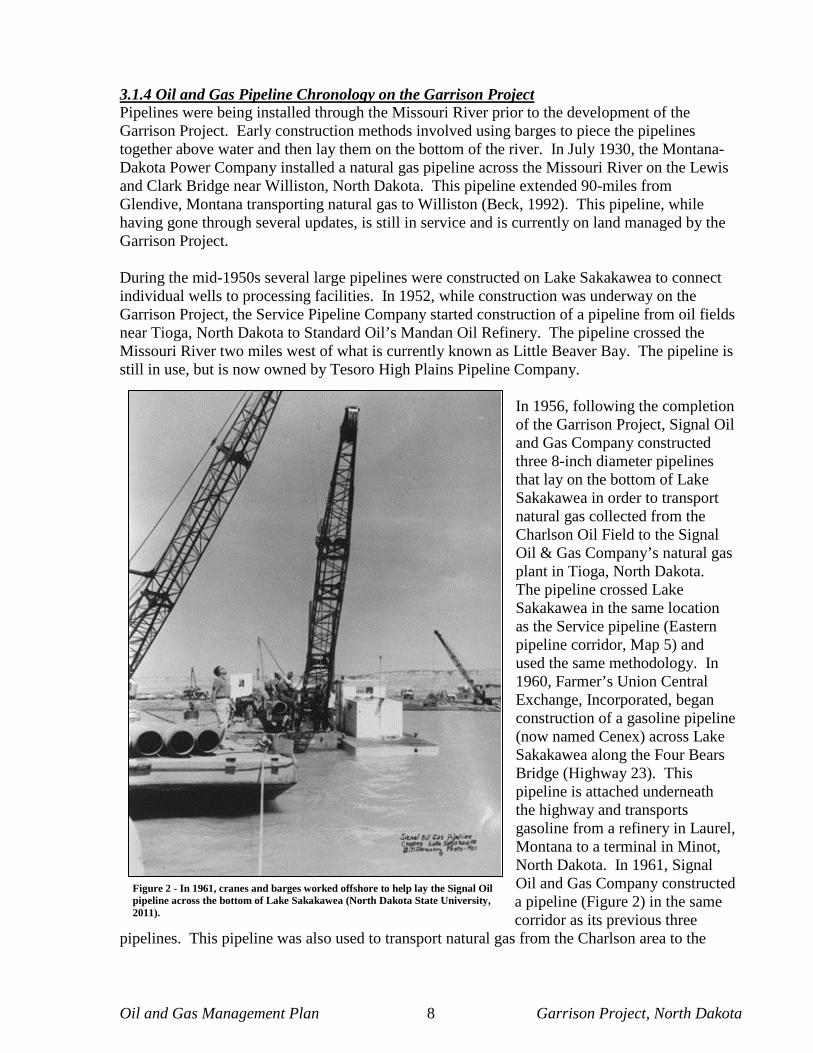
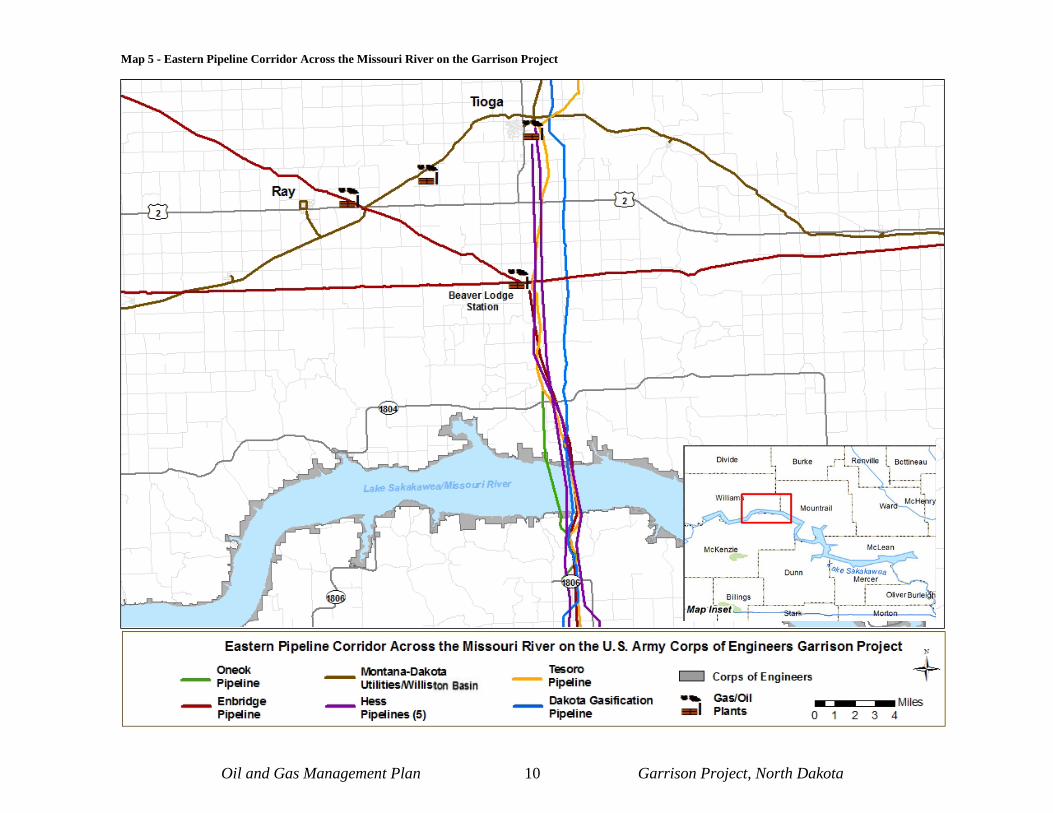
3.1.4 Oil and Gas Pipeline Chronology on the Garrison Project Pipelines were being installed through the Missouri River prior to the development of the Garrison Project. Early construction methods involved using barges to piece the pipelines together above water and then lay them on the bottom of the river. In July 1930, the Montana-Dakota Power Company installed a natural gas pipeline across the Missouri River on the Lewis and Clark Bridge near Williston, North Dakota. This pipeline extended 90-miles from Glendive, Montana transporting natural gas to Williston (Beck, 1992). This pipeline, while having gone through several updates, is still in service and is currently on land managed by the Garrison Project. During the mid-1950s several large pipelines were constructed on Lake Sakakawea to connect individual wells to processing facilities. In 1952, while construction was underway on the Garrison Project, the Service Pipeline Company started construction of a pipeline from oil fields near Tioga, North Dakota to Standard Oil’s Mandan Oil Refinery. The pipeline crossed the Missouri River two miles west of what is currently known as Little Beaver Bay. The pipeline is still in use, but is now owned by Tesoro High Plains Pipeline Company.
In 1956, following the completion of the Garrison Project, Signal Oil and Gas Company constructed three 8-inch diameter pipelines that lay on the bottom of Lake Sakakawea in order to transport natural gas collected from the Charlson Oil Field to the Signal Oil & Gas Company’s natural gas plant in Tioga, North Dakota. The pipeline crossed Lake Sakakawea in the same location as the Service pipeline (Eastern pipeline corridor, Map 5) and used the same methodology. In 1960, Farmer’s Union Central Exchange, Incorporated, began construction of a gasoline pipeline (now named Cenex) across Lake Sakakawea along the Four Bears Bridge (Highway 23). This pipeline is attached underneath the highway and transports gasoline from a refinery in Laurel, Montana to a terminal in Minot, North Dakota. In 1961, Signal Oil and Gas Company constructed a pipeline (Figure 2) in the same corridor as its previous three
pipelines. This pipeline was also used to transport natural gas from the Charlson area to the
Figure 2 - In 1961, cranes and barges worked offshore to help lay the Signal Oil pipeline across the bottom of Lake Sakakawea (North Dakota State University, 2011).

Oil and Gas Management Plan 9 Garrison Project, North Dakota
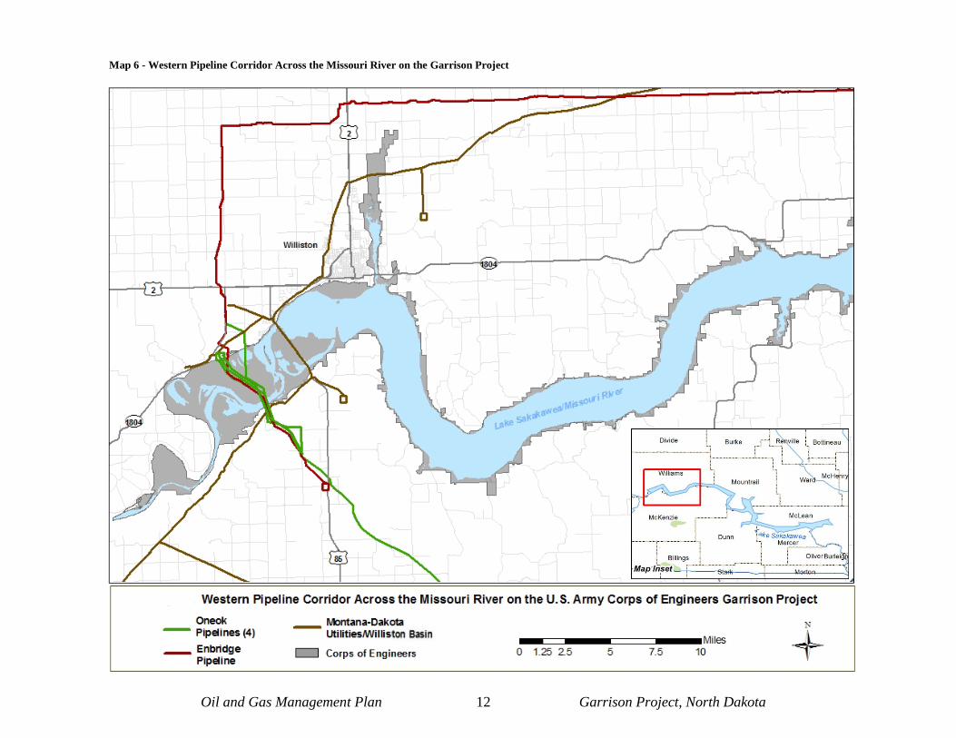
Tioga gas plant. In 1988, Amerada Hess Corporation purchased the four pipelines, and in 1992 began construction of a fifth pipeline under Lake Sakakawea. The new pipeline was used to transport natural gas from the Tioga gas plant, south to Watford City, North Dakota where it connects to the Northern Borders Pipeline. At the time it was built, the pipeline measured 11,500 feet and was considered the longest trenched freshwater pipeline in the country. Of these five pipelines owned by Amerada Hess Corporation, four are still in use and one has been abandoned. The construction of major pipelines across Lake Sakakawea roughly coincided with the boom and bust years for the oil and gas industry. While the pipelines built during the 1950s were concentrated around the Charlson field, the next big wave of pipelines was built during the 1980s, generally southwest of Williston servicing the Rosebud, Hardscrabble and Indian Hill oil fields west of Williston, North Dakota. In 1981, Philips Petroleum Company began construction of two 8-inch diameter pipelines under Lake Sakakawea and the Lewis and Clark Bottoms, just east of the town of Trenton, North Dakota. These pipelines were used to transport natural gas and crude oil in Richland County, Montana, and western North Dakota to the Philips petroleum and as processing plant near Trenton, North Dakota (Western pipeline corridor, Map 7). These pipelines are currently in operation. During 1999, one was sold to Bear Paw Energy Incorporated (now known as Oneok Rockies Midstream, LLC), and the second was sold to Enbridge Energy Company, Incorporated. The current oil boom has stimulated additional pipeline construction on the Garrison Project. In 2010, the Amerada Hess Corporation utilized its existing 10.5-inch concrete encased steel pipeline, which crosses Lake Sakakawea at the same site as the previous Hess pipelines, to construct the intrastate Keene Pipeline Project. The Keene Pipeline Project consisted of approximately 31 miles of 8-inch oil line that extended from the existing Lars Rothie field tank battery located in McKenzie County, North Dakota and continued north terminating at the existing Ramberg Trucking Facility in Williams County, North Dakota. The project was completed in 2011 and has a design capacity of 40,000 barrels of oil per day. In 2010, BakkenLink Pipeline LLC submitted a proposal to the Garrison Project for a 12-inch diameter crude oil pipeline extending from Beaver Lodge, North Dakota to a proposed crude oil rail loading facility located near Fryburg, North Dakota. Construction of the BakkenLink line may occur in late 2014 and would cross Lake Sakakawea at the Garrison Project’s established eastern pipeline corridor (Map 5) crossing at Little Beaver and Phelps Bay. The new station and associated pipeline will provide approximately 65,000 barrels per day and will have expansion capabilities up to 100,000 barrels per day of pipeline capacity to North Dakota.
This space left blank intentionally.
Oil and Gas Management Plan 10 Garrison Project, North Dakota
Map 5 - Eastern Pipeline Corridor Across the Missouri River on the Garrison Project

This space left blank intentionally.

Oil and Gas Management Plan 11 Garrison Project, North Dakota
Also in 2010, Enbridge Pipelines LLC proposed the SORTI-Dunn Pipeline Project. In 2011 the project was renamed to the Sanish Pipeline Project and the alignment was altered. The Sanish Project would consist of the construction of a new 8-inch and 10-inch diameter pipeline system starting approximately 45 miles south of Enbridge’s Beaver Lodge Station (near Tioga, North Dakota). The project would also consist of a new station to be constructed near Keene, North Dakota. The pipeline would cross Lake Sakakawea within the same pipeline corridor as the BakkenLink pipeline (Map 5). A major difference between the BakkenLink and the Enbridge pipelines is that Enbridge proposes to drill under the lakebed to complete the Lake Sakakawea crossing. The new station and associated pipeline would provide approximately 100,000 barrels per day of pipeline capacity to North Dakota. As of September, 2012 Enbridge has put this project on hold due to construction and financial challenges. Oneok Rockies Midstream, LLC constructed two new pipelines in 2013. These pipelines were constructed under Lake Sakakawea and the Lewis and Clark Bottoms, just east of the town of Trenton, North Dakota, adjacent to Oneok’s two other pipelines (Map 6). The pipelines are 12-inch and 16-inch diameter natural gas lines that transport hydrocarbons from wells located in the Bakken and Three Forks Formations to the Grasslands Plant in Sydney, Montana and the Garden Creek Plant northeast of Watford City, North Dakota (C. Backstrand, personal communication, 2011). In 2011, construction began on Oneok’s Myrmidon pipeline, a 12-inch diameter pipeline which was directionally bored under Lake Sakakawea to transport natural gas from Marathon Oil wells located in western Mountrail County to an existing Oneok system near Highway 73, just east of Watford City, in McKenzie County, North Dakota. This pipeline was completed in 2012 (Southern pipeline corridor, Map 7).
This space left blank intentionally.

This space left blank intentionally.
Oil and Gas Management Plan 12 Garrison Project, North Dakota
Map 6 - Western Pipeline Corridor Across the Missouri River on the Garrison Project

This space left blank intentionally.

Oil and Gas Management Plan 13 Garrison Project, North Dakota
Map 7 - Southern Pipeline Corridor Across the Missouri River on the Garrison Project

This space left blank intentionally.

Oil and Gas Management Plan 14 Garrison Project, North Dakota
3.2 Mineral Ownership The Garrison Project manages the entire 493,000 surface acreage; however, approximately three-quarters of the sub-surface mineral estate are owned by a matrix of non-federal entities, either Tribal, state, or privately owned (See Map 8 through Map 13). Those areas where the rights to the mineral estate have been separated or split from the surface estate are owned by different parties and are known as split or severed estate property. In the case of the Garrison Project, where most of the western two thirds of the project have “severed” mineral rights, the owner of the mineral rights has the right to use as much of the surface as is reasonably necessary to explore, produce and transport the minerals. However, the mineral rights owner must observe the rights of the surface owner and is required to exercise that degree of care and use, which is just consideration for the rights of the surface owner (North Dakota State University, 2011). Regulation and administration of mineral rights are defined by mineral severance deed language, private leases, industry standards, and federal and state laws/regulations. 4.0 Management Vision and Direction
4.1 Conformance with Corps Management Plans Currently, management on the Garrison Project is guided by the Garrison Dam/Lake Sakakawea Master Plan (Master Plan). The Master Plan provides guidance for appropriate uses, development, enhancement, protection, and conservation of the natural, cultural, and man-made resources at the Garrison Dam/Lake Sakakawea Project. When the Master Plan was completed in 2007, it included descriptions of factors influencing resource management and development, as well as strategies for developing and managing project resources over a wide range of reservoir elevations (U.S. Army Corps of Engineers, 2007). One resource that was not adequately addressed in the Master Plan was oil and gas management. This O&GMP is being developed to address the deficiencies in the existing Master Plan as they relate to oil and gas management on the Garrison Project, in order to ensure that proposed oil and gas exploration, development, production and rehabilitation projects do not unreasonably impact the surface estate and subsurface estate of the Garrison Project, including associated natural, cultural, socioeconomic, and aesthetic resources for statutorily authorized project purposes. When the Master Plan is updated, the management strategies of this O&GMP will be integrated into the latest revision.

This space left blank intentionally.

Oil and Gas Management Plan 15 Garrison Project, North Dakota
Map 8 - Mineral Ownership on the Garrison Project (1 of 6)
Williston

This space left blank intentionally.

Oil and Gas Management Plan 16 Garrison Project, North Dakota
Map 9 - Mineral Ownership on the Garrison Project (2 of 6)

This space left blank intentionally.

Oil and Gas Management Plan 17 Garrison Project, North Dakota
Map 10 - Mineral Ownership on the Garrison Project (3 of 6)
New Town

This space left blank intentionally.

Oil and Gas Management Plan 18 Garrison Project, North Dakota
Map 11 - Mineral Ownership on the Garrison Project (4 of 6)

This space left blank intentionally.

Oil and Gas Management Plan 19 Garrison Project, North Dakota
Map 12 - Mineral Ownership on the Garrison Project (5 of 6)

This space left blank intentionally.

Oil and Gas Management Plan 20 Garrison Project, North Dakota
Map 13 - Mineral Ownership on the Garrison Project (6 of 6)
Riverdale Pick City
Garrison Dam

This space left blank intentionally.

Oil and Gas Management Plan 21 Garrison Project, North Dakota
4.2 Management Vision The Garrison Project/Lake Sakakawea is a unique area, the management of which is described in the Master Plan. The O&GMP builds on this to provide a management vision for oil and gas activities that considers authorized Project purposes, including all the resource values and land uses in the area. 5.0 Roles and Responsibilities
5.1 Authorities Ownership of the mineral rights underlying the Garrison Project varies by tract (refer to Maps 8 through 13 above). The minerals may be owned outright by the federal government, may be third party owned, or some combination thereof. There may be subordination agreements or surface restrictions in place. It is also possible for the Bureau of Land Management (BLM) to lease any federally owned mineral interests beneath the surface of Project land. It is necessary to review and consider the specific ownership documentation of each tract in order to determine the rights and controls that the Corps has on said tracts.
5.1.1 Federally-Owned Minerals on the Garrison Project Under the multiple-use principle, federal minerals beneath the surface of Corps lands may be made available for mineral exploration and extraction, consistent with Garrison Project activities. Exclusions of minerals from exploration and extraction, and restrictions on exploration and extraction may be necessary and would be justified and based on Garrison Project consideration (Army Regulation (AR) 405-30). See Appendix E for AR 405-30. The primary statute governing oil and gas development on federally-managed lands is the General Leasing Act (30 U.S.C. 216 et. al.), the Mineral Leasing Act of 1920 (30 U.S.C. 181 et. seq.), as amended by the Federal Onshore Oil and Gas Leasing Reform Act of 1987. This statute authorizes the Secretary of the Interior, through the BLM, to issue leases to private individuals and corporations to extract federal oil and gas from public lands. While the Mineral Leasing Act authorizes BLM to issue oil and gas leases, it does not require that leases be issued (Darin & Stills, 2002). The BLM must obtain the Army’s approval and the Army, through the Engineering District, can place limitations in the lease regarding the extractions of these minerals (See AR 405-30; See, e.g, 43 CFR § 3503.20). If a developer approaches the BLM for access to a certain parcel or mineral interest, the BLM notifies the Corps and requests title information for the parcel and any use stipulationsthe Corps might require. The Real Estate Division for the Corps provides BLM the title information along with any stipulations (AR 405-30). The BLM would in turn inform the party interested in leasing the federal minerals of all of the stipulations. If the developer is still interested, the BLM follows its procedures to make the minerals available. The Corps has the final say in whether minerals will be made available, and the Assistant Secretary of the Army (ASA) has final approval on any non-availability determination.

Oil and Gas Management Plan 22 Garrison Project, North Dakota
5.1.2 State or Privately-Owned Minerals Underlying Garrison Project Managed Surface Acreage As stated in 5.1, the federal government does not own all of the mineral rights on Corps Project lands in North Dakota. The state of North Dakota, through the North Dakota State Land Department’s Minerals Management Division, issues leases for oil and gas exploration and development of state owned mineral rights, whileprivately owned minerals are often leased directly to oil and gas companies, either by the private owners or their legal representatives. Both state and private oil and gas rights on the Garrison Project are subject to state regulation as authorized under the laws of North Dakota through the North Dakota Industrial Commission’s Oil and Gas Division (NDOGD) and the North Dakota Department of Health (NDDH) under authority of the North Dakota Century Code. See N.D. CENT. CODE § 38-08 et. al. (2011). Owners of private and state oil and gas rights have a property right to develop their interests, which generally includes reasonable use of the surface to the extent necessary to accomplish such development. However, this does not mean their operations are free from limitation or reasonable regulation that might originate under state and/or federal law, whether pursuant to property law concepts or other legal authorities. Under applicable state and federal laws and regulations, The mineral owner, whether it is private or state, and/or the lessee must coordinate with the Garrison Project to use the federally-controlled surface. For all types of mineral leases where surface occupancy is approved under a lease, the lessees must obtain prior approval for any surface activities on Corps-managed lands (Title 43 – Public Lands: Interior Code of Federal Regulations [CFR] Subpart 3160). It is the Garrison Project’s responsibility to protect project purposes when allowing surface use. Moreover, while owners of oil and gas interests generally have the right to reasonable use of the surface to the extent necessary for private oil and gas exploration and development, they are not exempt from possible liability to the surface owner for damages stemming from such exploration and development. The Missouri River Projects, including Garrison, were constructed and are operated and maintained as authorized by the Flood Control Act of 1944 (1944 FCA). Lands necessary for Project purposes were acquired and are managed according to that authority, and the Corps has exclusive authority to manage lands and waters of the projects for the purposes for which they were authorized. See , Section 4, 1944 FCA (16 U.S.C. 460d). Moreover, the Corps has constitutional and other statutory authority to manage federal lands for federal purposes. For example, 33 U.S.C. § 408 makes it unlawful for any person to build upon, alter, deface, destroy, move, injure, or in any manner whatever, impair the usefulness of any work built by the United States for the preservation and improvement of any of its navigable waters or to prevent floods.
Federal courts have acknowledged this authority in the context of private oil and gas exploration and development on federal lands where the acquisition statute, like the 1944 FCA, granted the federal agency broad authority to regulate the use of the land for authorized purposes. Specific to the Garrison Project, Department of Defense policy has directed the Corps to promulgate regulations that subject private oil and gas exploration and development rights on the Garrison Project to terms and conditions or stipulations prior to any private oil and gas exploration and development company’s surface-disturbing activities (AR 405-30). It is important that Corps regulations not be so restrictive so as to become a “taking” under the 5th
Oil and Gas Management Plan 23 Garrison Project, North Dakota
Amendment to the U.S. Constitution. For this reason, all third party development of oil and gas reserves located on Corps project lands must be fully coordinated within the District.
5.1.3 State or Privately-Owned Minerals Accessed From State or Privately-owned Land Effective control of mineral extraction activities, particularly when the Corps does not own the necessary estates in real property to control development within the close proximity of dams and other structures, requires close coordination among the Garrison Project and the District Office, especially Operations, Real Estate, Engineering-Construction and Counsel. Operations personnel are often the first Corps employees to become aware of new or proposed mineral extraction activities near the Garrison Project. Mineral extraction activities (further discussed in Section 7.0) may include exploration operations, mining operations, drilling operations, production operations, reworking operations (including hydraulic fracturing) and high pressure pipeline operations. Real Estate personnel must investigate the location of activities and determine the federal real property interests in the location. Engineering-Construction personnel must evaluate any new or proposed activities in order to make determination whether said activity is compatible with the structural integrity of the dam and other major structures. The Corps’ ability to regulate and dictate private mineral extraction on adjacent private lands is largely untested and may be minimal. However, federal agencies have a duty to protect federal resources for authorized purposes, so this coordination is necessary even if it appears futile.
5.2 Roles and Responsibilities The outgrant of Garrison Project surfaces to applicants for the development and/or transportation of minerals will follow a seven step process as described below. 1) Applicant submits preliminary request to Garrison Project office detailing the proposed location of the development. Maps and public land survey legal descriptions should be included in this request. Inquiries concerning surface availability for oil and gas projects will be directed to the Corps’ Real Estate Division with information provided to the Lake Manager of the Garrison Project. This should be a written request submitted by the applicant. Each application shall clearly set out the mineral interest used as the basis for the request. 2) An on-site meeting will be held between the Garrison Project staff and the applicant. Prior to the meeting, the applicant would obtain permission to use laths to stake off extents of proposed development. The Garrison Project will notify the project proponent and set-up an on-site meeting at the earliest convenience of all parties involved. The project proponent will take the steps necessary to prepare for the meeting. The on-site meeting will provide an opportunity to view the proposed project location, review Corps of Engineers’ policy, answer questions, and identify reclamation requirements. At the on-site meeting the project proponent will be given an application package to complete and submit to the Garrison Project’s Lake Manager. Application information can be found in Appendix A. 3) The applicant will submit a complete application package and pay the current administrative processing fee. 4) If the Corps must approve the use of Corps property prior to the exploration or extraction activity, the National Environmental Policy Act (NEPA) must be completed by the Corps or, as authorized, by the applicant under in accordance with Title 40 – Protection of Environment CFR

Oil and Gas Management Plan 24 Garrison Project, North Dakota
Sections 1506.5(a) and 1506.5(b), which allows an applicant to prepare an EA for a federal action. The applicant will follow the outline in Appendix B to comply with. The importance of selecting a firm who is competent in preparing NEPA documents cannot be overstated. Significant delays and increased costs could be recognized if an experienced firm is not selected. The Corps would review qualifications of a selected firm prior to authorizing it as the agency’s non-federal sponsor for completion of NEPA requirements. 5) The complete application package will be routed from the Garrison Project to the Omaha District Operations Natural Resource Office for review and comment by District offices. This will follow the Operations Real Estate Review Policy 2011. If appropriate, the District will draft a Finding of No Significant Impact which would be signed by the Omaha District Commander. The consolidated package will be routed to the Omaha District Real Estate Division for approval before being routed back to the Garrison Project Real Estate Office for issuance of lease, land grant or easement. 6) The applicant will receive all required permits and appropriate real estate instruments in order for project development to begin. The applicant will comply with the commitments made in the NEPA document and conditions outlined in Appendix D. 7) Interim reclamation, monitoring and final reclamation will be completed as outlined in Appendix D. As previously mentioned, the Garrison Project may have limited discretion in precluding development of privately-owned minerals. To the extent permitted by the geologic target, well spacing, and drilling and production technology, the locations selected for oil and gas development projects should be planned to minimize long-term disruption of the surface and to promote successful reclamation. Design and construction techniques should be employed that would minimize surface disturbance and the associated effects of proposed developments and enable successful reclamation of the site. Best management practices (BMPs), as outlined in Appendix D, can be used to reduce negative impacts to the existing environment from oil and gas development. If an impasse is reached on the location of a site, it will be necessary to evaluate the Garrison Project’s position in light of statutory authority and legal precedent. A Corps attorney would be contacted for an official legal opinion regarding conflict resolution. Oil and gas exploration and development proposals are subject to NEPA analysis, and many other laws and regulations outlined in Sections 6.2, 6.3, and 6.4. Standards and guidelines that identify reasonable and necessary measures would be identified to minimize or mitigate impacts to surface resources.
The environmental analysis would be completed by the applicant, under supervision of the Corps, and would require the submittal of the following components as part of the application process.
Map of the Planned Development – A map will be provided showing locations and dimensions of all facilities. Generic maps will not be accepted. Digital and hard copies should be provided. The hard copies should be as-built drawings. Maps must be accurate and depict the actual location of the well pad and attendant features including temporary facilities, roads or any other

Oil and Gas Management Plan 25 Garrison Project, North Dakota
disturbances. These facilities include, but are not limited to, well sites, roads, tank batteries, utility and collection lines, any pipelines, storage areas for equipment and supplies, spoil piles, location of erosion control devices, fences, cattle guards, signage, flaring locations, generators, compressors, meters, and other facilities necessary for production or operation. Initial disturbed footprint and areas that would be reclaimed should clearly be shown. Quantities and measurements should also be accurate and specific to the project. These maps should also show drainage patterns of the area and what efforts are being made to deter runoff from reaching Lake Sakakawea. Environmental Assessment (EA) or Environmental Impact Statement (EIS) – Federal agencies make preliminary determinations of whether an action is a Major Federal Action which has significant environmental effects by classifying actions into three general categories: actions with significant effects that automatically require preparation of an EIS; actions with no significant effects that are categorically excluded from compliance with NEPA; and all other actions for which a determination of the significance of environmental effects must be made on a case-by-case basis and where an EA is completed (Fogleman, 1990). Environmental effects can be reduced by implementing best management practices described in Appendix D. Due to the intensity of development in the region, it is presumed that most, if not all, oil and gas exploration and development projects on the Garrison Project will have direct, indirect and cumulative environmental effects that cannot be categorically excluded and will require preparation of either an EA or EIS. Guidelines for preparing the NEPA document can be found in Appendix B. The Corps must independently evaluate and verify the information and analysis undertaken in the EA and take full responsibility for the scope and content contained within the document.
Surface Use Plan of Operation – Regardless of mineral ownership, the Surface Use Plan of Operation (SUPO) will include a schedule of construction and drilling activities. This schedule will include the beginning and ending dates for road construction, construction of the well site, drilling, hydrofracturing, and completion of wells. The Plan of Operation will also identify intended use of roads, trails, and other facilities. Standards developed by the Bureau of Land Management’s “Gold Book” should be utilized except where Corps BMPs (Appendix D) supersede BLM requirements (i.e. no open pits) based on proximity to Lake Sakakawea.
Erosion and Sedimentation Control/Storm Water Management Plan – A site-specific plan to minimize erosion and prevent sedimentation of streams, drainages and wetlands will be developed by the operator and must be in accordance with the federal and state laws. Emergency Response and Spill Prevention, Control, and Countermeasure (SPCC) Plan – SPCC plans are prepared and implemented as required by the U.S. Environmental Protection Agency (EPA) regulation contained in Title 40, CFR Part 112. A non-transportation related facility is subject to SPCC regulations if: the aggregate above ground capacity of the facility exceeds 1,320 gallons (excluding those tanks and oil filled equipment below 55 gallons in capacity) and if, due to its location, the facility could reasonably be expected to discharge any amounts of hazardous material or oil into or upon the navigable waters adjoining shorelines of the United States. An emergency response component should be included in the SPCC plan which should outline actions taken if accidental spills occur at an oil and gas development site. These actions would include, but are not limited to, notification of spills to the Garrison Project, proper local
Oil and Gas Management Plan 26 Garrison Project, North Dakota
authorities, state regulatory agencies and the EPA. The site-specific plan would be developed in coordination with the Garrison Project staff. Hydrogen Sulfide (H2S) Contingency Plan – An H2S Contingency Plan shall be developed for drilling operations where formations would be penetrated which have zones known to contain, or which could reasonably be expected to contain, concentrations of H2S at or exceeding 100 parts per million. The U.S. Bureau of Land Management’s Onshore Oil and Gas Order No. 6 describes the minimum standards and requirements and contains applicability criteria when a Public Protection Plan would also be required to be filed, based on the H2S radius of exposure while drilling. Onshore Oil and Gas Order No. 2 specifies that hydrogen sulfide safety and monitoring equipment would be available and in use where atmospheric concentrations of hydrogen sulfide of 20 parts per million or greater were anticipated. Sewage Containment Plan – All applicants must submit a Sewage Containment Plan to ensure the proper function, maintenance and disposal of sewage during the development of oil and gas projects. An adequate number of portable chemical toilets (1 toilet/10 people/40 hours) shall be present on or near the development site from the beginning of construction through completion of the well. All sewage waste must be disposed of in state and/or county-approved facilities. Records shall be kept and made available upon request. No sewage wastes shall be placed within a reserve pit, buried on location, and/or disposed of on Garrison Project Lands. The applicant must comply with the North Dakota Department of Health requirements and regulations defined or promulgated for “sewage management.” Groundwater Monitoring Plan – Garrison Project lands abut Lake Sakakawea, an important drinking water resource to inhabitants of the Missouri River Basin. Surrounding aquifers are connected to the lake. The Garrison Project has a responsibility to protect the ground and surface water resources that lie within its management boundaries. Aquifers beneath surfaces of the Garrison Project connect to Lake Sakakawea and any contamination of these aquifers would directly impact the water quality of the lake. To detect and prevent groundwater contamination, the applicant shall set up a localized groundwater monitoring network which will include at least two piezometers to ensure well development does not have adverse effects on aquifers. The piezometers should be set up so they transect the groundwater gradient. The applicant is responsible for the cost to install the wells and housing to protect the wells. The wells would be locked to avoid unauthorized entry. An independent third party approved by the Garrison Project would sample the wells for common water quality parameters to establish a baseline for the project area. During well development (i.e. hydraulic fracturing processes) and during well production, the independent third party would be responsible for taking water quality samples and submitting, as part of the monitoring report, the results to the applicant and the Garrison Project. The applicant is responsible for all payment while the sampling is being done. Standard water quality sampling methodologies should be used including the use of blind duplicates to verify integrity of sample results. Water quality sampling protocols would be provided by the U.S. Army Corps of Engineers – Omaha District. Sampling and reporting would continue for the life of the well, or until the Garrison Project determines no effect to aquifers has occurred due to well development.

Oil and Gas Management Plan 27 Garrison Project, North Dakota
Reclamation and Monitoring Plan – A Reclamation and Monitoring Plan would be developed for all surface disturbing activities and would become part of the proposed action in the NEPA document. The level of detail for the reclamation and monitoring plan shall reflect: the complexity of the project, the environmental concerns, and the reclamation potential for the site. Well pads would be reclaimed to the maximum extent practicable by arranging facilities so resource retrieval and maintenance can be performed at a minimum expense to the surrounding landscape. These plans shall also incorporate any program or regulatory specific requirements for reclamation. The reclamation plan shall address short term stabilization to facilitate long term reclamation. Not reclaiming disturbed portions of a pad based on speculation that future wells may be constructed is not allowed on the Garrison Project. The reclamation plan would also outline performance standards and monitoring requirements. The plan is considered complete when all the reclamation and monitoring requirements are described in detail, and the Garrison Project reviews and accepts the reclamation plan. A monitoring report should be submitted to the Garrison Project by December 31 of any given calendar year for the life of the well. The monitoring report would include photographs of the site documenting the integrity of the site, i.e. well maintained fences, cattle guards, signage, reclamation progress and other observations as deemed appropriate by the Garrison Project. Reclamation success would be evaluated by comparing existing conditions to the performance standards developed within the reclamation plan. After completing the above requirements and following the signing of the decision document by the Corps’ Omaha District Commander, the applicant would:
• provide the name, address, and phone number of a designated field representative who would be familiar with all phases of the project; and
• provide copies of the state’s approved drilling permit(s) before surface disturbing
activities would occur. The private oil and gas exploration and development operator or developer will be responsible for the repair or replacement of Corps surface improvements, such as fencing, recreation facilities or other facilities impacted by development or operations.
5.3 Implementation The Corps will implement its authority through review and evaluation of site-specific oil and gas exploration and development operational proposals and the subsequent issuance of a formal permitting document to the oil and gas exploration and development companies. Application of programmatic direction is to be focused on reasonable regulation of development to protect surface resources and not to act in a manner that prohibits private oil and gas rights development. As the Corps applies the design criteria in the preferred alternative, the Garrison Project would work cooperatively with the oil and gas exploration and development company to resolve any concerns it has related to the proposed plan of operations, recognizing the right of the private oil and gas exploration and development company to develop its oil and gas. If circumstances

Oil and Gas Management Plan 28 Garrison Project, North Dakota
warrant, on a case-specific basis, an authorization to the applicant to operate may contain terms and conditions different from the standards set forth by the design criteria. In making such a determination, the Corps will consider operational impacts at the site-specific level, the operational impacts, as well as necessary resource protection. Along with the legal authority to protect surface resources comes the responsibility to comply with applicable federal laws such as the Endangered Species Act, Clean Water Act, Clean Air Act, National Historic Preservation Act and many others. A more comprehensive list can be found in Appendix B. The Corps works with the U.S. Fish & Wildlife Service (USFWS), Environmental Protection Agency (EPA), North Dakota Department of Health (NDDH), North Dakota Department of Game and Fish (NDG&F), North Dakota State Historic Preservation Office (SHPO) and many other public and private entities to ensure compliance with these legal obligations through its multi-stage Corps planning and site specific decision-making process. A more comprehensive up-to-date contact list would be available from the Garrison Project at the time of application. A formal authorization to operate will be issued by the appropriate Corps employee (to be determined at a later date) and will contain terms and conditions enforceable against the applicant. When issued, such authorization will address any other foreseeable issues that could require additional Corps approval, i.e., use of Corps roads, construction/location of new roads on Garrison Project lands, and location of pipelines and utilities.
6.0 Administrative Process
6.1 Legislation Framework
6.1.1 Corps Regulations Under the Flood Control Act of 1944, as amended, the Corps is responsible for managing all activities on the Garrison Project, which includes private oil and gas exploration, and development on the federally-managed surface lands. It is the policy of the Corps to protect its resources to the maximum extent possible without infringing on the rights of mineral owners. The following sections describe the legal framework under which the Corps regulates private oil and gas exploration and development that takes place on Corps surface lands when the Corps does and does not own the mineral rights. In addition to Corps regulations concerning oil and gas activities, other statutes and regulations are cited.
6.1.2 Excepted Mineral Rights On much of the Garrison Project, the mineral owner holds excepted rights. Excepted rights occur when oil and gas rights are owned by third parties at the time the Corps acquired title to the lands. The owner of excepted oil and gas rights has the right to sell, lease, explore for, and remove those minerals subject to the terms of the instrument by which that interest was acquired or reserved and to the state laws governing protection of the surface and the rights of the surface owner. When a mineral owner decides to exercise his or her rights, the Garrison Project would determine the government’s existing rights with regard to the mineral estate and what controls can and should be placed on the activities under the Rivers and Harbors Appropriation Act (1899).

Oil and Gas Management Plan 29 Garrison Project, North Dakota
In addition to the Rivers and Harbors Appropriation Act (1899), excepted rights are addressed in AR 405-30, Mineral Exploration and Extraction (see Appendix E). This regulation assigns responsibilities and sets policies and procedures for mineral exploration and extraction on Army-controlled lands. A few notable policies are provided below.
• The Secretary of the Army or designee reserves the right to require suspension of
operations if the Army needs the lease areas for a purpose that is not compatible with oil and gas operations.
• If the project manager finds an imminent danger to safety or security, the project manager
may order an immediate stop of such activities.
• The operator will immediately stop work if contamination is found in the operating area.
6.1.3 Navigable Waters The Rivers and Harbors Appropriation Act of 1899, specifically Parts 320 to 327 and Part 330, prescribe regulations that identify the Corps’ general policies to implement Section 404 of the Clean Water Act. Part 320 outlines the Corps’ general policies; Part 321 describes permit regulations for dams and dikes; Part 322 describes regulations for structures; Part 323 describes permit regulations for dredged materials; Part 325 describes permit regulations for discharges to navigable waters and wetlands; Part 326 describes enforcement policies; Part 328 defines navigable waters regulations; and Part 330 describes nationwide permit program regulations.
6.2 Other Laws Relating to Oil and Gas Activity on Corps-Managed Lands
6.2.1 National Environmental Policy Act (NEPA) The National Environmental Policy Act of 1969 (42 United States Code [USC] 4321-4370f) requires federal agencies to analyze the environmental impact of their actions, incorporate environmental information, and utilize public participation, as appropriate, in the planning and implementation of their actions. NEPA compliance is required when a federal agency takes an action. Once the proposal to undertake an action is conceptualized and any reasonable alternatives have been developed, the agency must determine if the action has the potential to affect the quality of the human environment. The decision of whether to grant a surface real estate easement for the proposed project is the federal action by the Corps requiring compliance with NEPA, as amended, the Council on Environmental Quality’s (CEQ) regulations for implementing NEPA (40 CFR 1500-1508), the Corps’ regulations for implementing NEPA (Engineering Regulation 200-2-2), and other applicable environmental laws and regulations. As discussed above, although Corps regulations explicitly recognize that the Corps has the right and is obligated to prevent unreasonable degradation of the surface resources of the Garrison Project (AR 405-30), the Corps does not have the authority to unreasonably deny a mineral owner’s activities on the Garrison Project. It would be expected that the applicants would modify project design to prevent unreasonable degradation. Permits, reviews and consultation requirements of other agencies and Tribes must be obtained before the federal action can be implemented.

Oil and Gas Management Plan 30 Garrison Project, North Dakota
6.2.2 National Historic Preservation Act (NHPA) of 1966, as amended Section 106 of the NHPA requires federal agencies to assess the effects of an undertaking on historical and cultural resource sites. This is accomplished by inventorying proposed disturbance areas or area of potential effect, evaluating site importance and eligibility to the National Register of Historic Places (NRHP), assessing the effect of the undertaking on NRHP-eligible sites, and consulting with appropriate historic preservation agencies.
6.2.3 Archaeological Resources Protection Act of 1979 The Archaeological Resources Protection Act of 1979 (16 USC 470aa-470mm) and amendments provide for the protection of archaeological resources on public and Native American lands and provide for exchange of information between governmental entities and academic or private archaeological researchers. An archaeological resource under this act is defined as material remains of past human life or activities that are of archaeological interest and includes but not limited to pottery, basketry, bottles, weapons, tools, structures, rock paintings or carvings, intaglios, graves, and human skeletal materials.
6.2.4 Migratory Bird Treaty Act and Migratory Bird Conservation Act The Migratory Bird Treaty Act (MBTA) (16 USC 703-712) prohibits pursuing, hunting, taking, capturing, killing, or selling migratory birds, as identified in the act, through international conventions between the United States and Great Britain, Mexico, Japan, Canada, and Russia.
6.2.5 Endangered Species Act The Endangered Species Act (ESA) (16 USC 1531-1544) provides for the protection of endangered and threatened species and the habitats upon which they depend. Section 7 of the act requires federal agencies, to consult with the Secretary of the Interior or the Secretary of Commerce in cases where the agencies’ action may affect a listed species, to ensure that actions they authorize, fund, or carry out are not likely to jeopardize the continued existence of threatened or endangered species or result in the destruction or adverse modification of critical habitat for these species.
6.2.6 Fish and Wildlife Coordination Act The purpose of the Fish and Wildlife Coordination Act (16 USC 661 et seq.) is to recognize the contribution of wildlife resources to the Nation, the increasing public interest and significance thereof due to expansion of our national economy and other factors, and to provide that wildlife conservation receives equal consideration and be coordinated with other features of water-resources development programs. The Secretary of the Interior, through the USFWS is authorized to assist and cooperate with federal, state and public or private agencies and organizations in the conservation and rehabilitation of wildlife. Section 662(a) of this act provides that whenever the waters of any stream or other body of water are proposed to be impounded, diverted, the channel deepened or otherwise controlled or modified, the Corps shall consult with the USFWS, the National Marine Fisheries Service (NMFS) as appropriate, and the agency administering the wildlife resources of the state. The consultation shall consider conservation of wildlife resources with the view of preventing loss of and damages to such resources as well as providing for development and improvement in connection with such water resources development.

Oil and Gas Management Plan 31 Garrison Project, North Dakota
6.3 Other Federal Regulations and Considerations Oil and gas exploration and development activities also are governed by a number of other federal regulatory programs and human environmental conditions. Consideration of the items in the list below should be evaluated when analyzing potential impacts of a proposed action. Additional considerations may be warranted and would be evaluated on a site-specific basis.
• Clean Water Act (CWA) • Clean Air Act (CAA) • American Indian Religious Freedom Act (AIRFA) • Native American Grave Protection and Repatriation Act (NAGPRA) • Resource Conservation Recovery Act (RCRA) • Occupational Health and Safety Administration (OSHA) regulations • Department of Transportation (DOT) regulations • Floodplain management • Prime or unique farmland • State or national parks, forests, conservation areas or other areas of recreational,
ecological, scenic, or aesthetic importance • Wild and scenic rivers • Tribal concerns • Environmental justice • General public
6.4 State Regulations and Rules The major regulatory agencies and programs under which private oil and gas exploration and development activities are regulated are discussed below.
6.4.1 North Dakota Industrial Commission’s Oil and Gas Division The NDOGD has jurisdiction over the production of oil and gas in North Dakota. This commission administers the statutes and administrative rules regulating the drilling and plugging of wells, the restoration of drilling and production sites, the disposal of saltwater and oil field wastes, the spacing of wells, and the filing of reports on well location, drilling, and production.
6.4.2 North Dakota Department of Health Major regulatory programs of the NDDH that apply to private oil and gas exploration and development activities include the regulation of storm water discharges during construction activities, storage and disposal of solid waste, air emissions sources, and surface and ground water protection.

Oil and Gas Management Plan 32 Garrison Project, North Dakota
6.4.3 Other State Regulations and Rules Oil and gas exploration and development activities also are governed by a number of other state regulatory programs. The list below is not intended to be exhaustive:
• North Dakota State Land Department • North Dakota Game and Fish Department • North Dakota State Historical Society • North Dakota State Water Commission
7.0 Description of Oil and Gas Development Activity
7.1 Description of Mineral Resources Shale oil and gas wells installed in the Williston Basin of North Dakota typically produce for a much longer period than wells drilled in conventional reservoirs. Unconventional reservoirs like the Bakken and Three Forks Formations are capable of delivering profitable production for decades through the application of advanced technology and large manufacturing-like development programs that capture economies of scale. Original assessments of recoverable reserves from conventional reservoirs typically identify the majority of the resource in place, with a limited upside potential. Conventional reservoirs are typically produced over a five-to ten-year lifespan. In contrast, original assessments of unconventional gas reservoirs often show only a small percentage of what is ultimately recoverable. Unconventional development involves drilling numerous wells in a repeatable manner. These reservoirs are produced over 30 years or more. As a result, the company can take advantage of operational efficiencies and new technologies, developed over time, to reduce costs, extend the life of the wells, and increase recoveries (Moss, 2008). There are a total of 576 oil fields in North Dakota, with the majority occurring in the western third of the state. Portions of 45 of these oil fields occur on the Garrison Project (Map 15) providing oil and gas. This section describes the existing hydrocarbon resource and methods used to extract it.
7.1.1 Oil Resources The Williston Basin is a large 200,000 square mile sedimentary basin in western North Dakota, northwestern South Dakota, eastern Montana, southern Saskatchewan, and extreme southwestern Manitoba, and is known for its rich deposits of petroleum (Map 14). It is a geologic structural basin transected by the Missouri River, which is an oval-shaped depression extending approximately 475 miles (764 km) north-south and 300 miles (480 km) east-west (Gibson, 1995). Map 14 - The Williston Basin extends to southwestern Manitoba, east-
central North Dakota, northwestern South Dakota, eastern Montana, and southern Saskatchewan (Energy and Environmental Research Center, 2011).
Oil and Gas Management Plan 33 Garrison Project, North Dakota
Within the Williston Basin, the two to possibly three petroleum rich formations are the Bakken, Three Forks and Lodgepole, with the Bakken being the most productive to date followed by the Three Forks. The Lodgepole formation is currently being studied to determine its petroleum potential. A significant amount of data suggests that the lower 110 feet of the Lodgepole Formation may be an economically-viable oil bearing horizon (Neset, 2009).
This space left blank intentionally.

This space left blank intentionally.
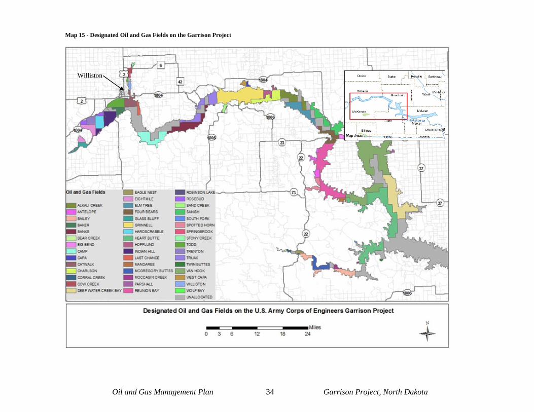
Oil and Gas Management Plan 34 Garrison Project, North Dakota
Map 15 - Designated Oil and Gas Fields on the Garrison Project
Williston

This space left blank intentionally.

Oil and Gas Management Plan 35 Garrison Project, North Dakota
To date, the Bakken Formation has been found to be one of the largest contiguous deposits of oil and gas in the United States. This formation is a Devonian- to Mississippian-aged sedimentary unit consisting of organic rich shale in the upper and lower layers of the sediment, and is the primary petroleum source rocks that form the continuous reservoir for hydrocarbons in the Bakken Formation (Pollastro et al., 2008). It is 11,000 feet deep in the depocenter of the basin in the southwest corner of North Dakota. The depth of the Bakken rises to 4,500 feet deep on the eastern edge of the basin, and up to 3,100 feet deep (950 meters) on the northern edge, across the Canadian border in Manitoba and Saskatchewan. The formation’s thickness varies throughout the Williston Basin, but generally thickens toward the basin’s center, reaching a maximum thickness of 145 feet (Webster, 1992). The Bakken
Formation is located between the overlying 900-foot thick Lodgepole and the underlying 250-foot thick Three Forks Formation (Figure 3). As the Williston Basin subsided, these massive low-permeability carbonates acted as seals around the Bakken Formation (Grape, 2006).
The Late Devonian-aged Three Forks Formation is present only in the subsurface of the Williston Basin and extends over approximately two-thirds of the state of North Dakota. The formation consists of clean and argillaceous micrite and dolomicrite containing varying amounts of silt, sand and anhydrite. The Three Forks Formation attains a maximum thickness of 270 feet and has a well-defined depocenter that covers Mountrail, Dunn and eastern McKenzie Counties (LeFever & Nordeng, 2008). Within the Three Forks Formation, the Sanish zone is a sandy interval found at the top of the formation and is usually 10 to 20-feet thick. It is in this area that many experts feel the majority of the recoverable petroleum can be found, with an estimate of 1.9 billion barrels of recoverable oil (Energy Policy Research Foundation, Inc., 2011). Designated oil and gas fields in North Dakota are depicted in Map 15.
7.1.2 Natural Gas Resources Most of the natural gas found in North Dakota is shale gas. Shale gas is a natural gas produced from shale formations that typically function as both the reservoir and source for the natural gas. In terms of its chemical makeup, shale gas is typically a dry gas primarily composed of methane (90% or more methane), but some formations do produce wet gas (U.S. Department of Energy, 2009). In North Dakota natural gas is typically found at depths of up to 10,000 feet and is processed as a by-product of oil production from horizontal drilling and hydraulic fracturing (Pipkin et al., 2010), and as the natural gas production rate curve for North Dakota shows that yearly production has mirrored that of oil production (Stilwell et al., 2009).
Figure 3 - Generalized stratigraphic column of key oil and gas rock formations in the Williston Basin.
Oil and Gas Management Plan 36 Garrison Project, North Dakota
The United States Geological Survey believes that approximately 1.85 trillion cubic feet of “dry” natural gas and 148 million barrels of natural gas liquids are technically recoverable in the Bakken Shale Formation (Pollastro et al., 2008), but until natural gas recovery becomes more viable economically and transportation and processing constraints alleviated, much of the natural gas will be flared off as a waste product of oil drilling.
As of September 2011, 30% of the natural gas produced in North Dakota was burned as waste, an increase of 1,200% since 2004 when Bakken production began showing growth. No other major domestic oil field currently flares that much. Oil and gas industry representatives argue that they cannot afford to build new pipelines and processing plants to capture and sell the gas until they actually drill oil wells and calculate how much gas will bubble out of the oil. Also, reinjection of the carbon dioxide, commonly done in conventional oil fields, is more difficult and expensive in less permeable shale fields, such as the Bakken (Krauss, 2011). Developers typically are willing to pipe natural gas, as it is a valuable commodity, if nearby pipeline infrastructure is located within a reasonable distance from a new pad construction projects.
7.1.3 Coalbed Gas Within the Williston Basin of North Dakota the U.S. Geological Survey (2001) has identified Cretaceous and Tertiary coal beds. However, no quantitative assessments of potential coalbed natural gas resources associated with these coals have yet to be performed (Stilwell et al., 2009). Presently, there is no coalbed natural gas production on the Garrison Project, nor are there any exploration activities. Future coalbed gas exploration in North Dakota is expected to be minimal (Stilwell et al., 2009) and on the Garrison Project it is expected to be non-existent. Unless significant discoveries of gas in coalbeds are made, the Garrison Project will not address coalbed gas development in this O&GMP.
7.2 Stages of Oil and Gas Development Exploration and development activities include seismic exploration, site selection, well drilling, well completion, well stimulation, oil and gas production, transportation and reclamation. Production operations which would begin after well stimulation include primary and secondary recovery, production collection, produced fluid treatment, and waste management. Once the well is no longer economically viable, it will be plugged, abandoned, and reclaimed.
7.2.1 Exploration Scientific exploration for oil, in the modern sense, began in 1912 when geologists were first involved in the discovery of the Cushing Field in Oklahoma, USA. The fundamental process remains the same, but modern technology and engineering have vastly improved performance and safety (E&P Forum & UNEP IE, 1997).
Current scientific exploratory activities used to identify and characterize the extent of oil and gas reserves include:
• studying and mapping of surface geologic features to recognize potential oil and gas
traps (e.g. remote sensing);
• drilling exploratory or test wells to look for oil and gas; and

Oil and Gas Management Plan 37 Garrison Project, North Dakota
• using seismic methods to map the subsurface structures and determine potential for
producible oil and gas.
Seismic exploration further defines the character of the underlaying geology that may hold hydrocarbon reserves. It is an extensive on-the-ground activity that involves several components:
• Seismic surveys delineate rock layers by measuring the speed of shock waves as they move through the subsurface reflecting and travelling at different speeds through different rock types. The strength and timing of the reflected shock waves are measured at the surface by geophones, which are connected to a line laid along a predetermined course. The line is connected to a machine that records the signals (Sumi, 2005).
• The shock waves used in seismic surveys are generally caused by an explosive
charge set either below the surface or slightly above the surface. For charges set below the surface a 50-pound charge is used at a depth of between 25 – 200 feet. Charges set above the ground’s surface are usually a 2.5 to 5-pound charge. In place of explosive charges, thumper trucks or weight drop trucks may be utilized. These trucks drop a heavy weight from about six feet above the ground to produce the shock waves needed for the surveys. Another type of overland seismic survey method is the vibroseis or seismic vibrator which sends energy signals into the earth over an extended period of time through the use of a hydraulic vibrator mounted to a vehicle.
• For seismic surveys performed over water the air gun is the most commonly utilized
survey method. An air gun consists of pneumatic chambers that are pressurized with compressed air at pressures from 2,000 – 3,000 pounds per square inch. The air gun array is submerged below the water surface and is towed behind a boat. When the air gun is fired, pulses of acoustic energy are produced causing the shock waves needed for data collection (Peterson, 2004).
• Seismic surveys cannot identify oil and gas accumulations directly; they are only a
tool that can indicate the potential for reserves. The presence of oil and gas can only be confirmed by actual drilling. If preliminary tests indicate a likelihood of oil and gas then an exploratory well may be drilled (Sumi, 2005).
• Since 2003, five seismic surveys have been completed on the Garrison Project: the
Robinson Lake, Berthold, South Nesson, Baker 3-D and Cinco 3-D surveys. One survey, Hess Stony Creek, is completing a study in the fall of 2012 on potential acoustic impacts to federally-listed and state species of concern in Lake Sakakawea. Several others have been proposed and are in various stages of planning (Map 16).

This space left blank intentionally.
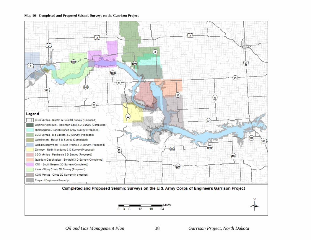
Oil and Gas Management Plan 38 Garrison Project, North Dakota
Map 16 - Completed and Proposed Seismic Surveys on the Garrison Project

This space left blank intentionally.

Oil and Gas Management Plan 39 Garrison Project, North Dakota
7.2.2 Site Selection Before an exploratory well can be drilled, an Application to Drill must be approved by the NDOGD, as well as the submittal of appropriate documentation outlined in Appendix A to the Garrison Project. The selection of any well site is governed by three primary variables: (1) the probability of finding hydrocarbons in specific locations as indicated by geological and geophysical data, (2) the company holding satisfactory mineral and surface leases or agreements granting drilling and production, and (3) the opportunities and constraints presented by the physical characteristics of the site being considered. To minimize risks to Lake Sakakawea, oil and gas wells should be setback as far from drainageways as possible. Appendix D contains more details on what measures should be undertaken in order to minimize potential impacts to the lake. Once a site is selected, the applicant should plan the development to maximize reclamation while the well is a producer. The well and attendant facilities should be arranged to reduce short term effects on the surrounding environmental. Well pad layout must be approved by the Garrison Project.
7.2.3 Drilling Exploratory drilling is used to verify if geologic rock formations have accumulations of oil and gas, and if the site can produce enough oil and gas to make it economically viable to proceed with further development. While a well site may be exploratory in nature, numerous steps need to occur before any knowledge about the oil and gas potential can be determined. Once a drill site has been determined, drilling operations then require construction of access roads, drill pads and work trailers. See figure 4 for a typical well pad layout. Once these are constructed, a drilling rig needs to be erected along with the installation of equipment to supply electricity, compressed air, and water for the operation. Storage facilities may also need to be installed. New well pads generally range from three to five acres and are stripped of vegetation, leveled and covered with gravel or scoria. Usually, the pad accommodates the drilling rig, work trailers, and other attendant features. Access roads to new well sites average 2.9 acres of surface disturbance in western North Dakota (Stilwell et al., 2009). Drill rig transport to the well site and on-site assembly typically takes seven days. Once the drill rig is erected the drilling can begin and it typically operates 24 hours a day, 7 days a week for 30 - 35 days (McCain and Associates, Inc., 2009). Transport of materials to the well site requires a developed transportation system. Oil and gas specialists in Colorado estimate that the “average” oil and gas well requires 320 to 1,365 truckloads of equipment and materials to bring a well into production. While the following information provides wide-ranging estimates, it is still helpful to understand the large amount of truck traffic that will be associated with any oil or gas well development project. Estimates are as follows (Moss, 2008):
New Well Development Drill Pad and Road Construction Equipment – 10 to 45 truckloads Drilling Rig – 30 truckloads

Oil and Gas Management Plan 40 Garrison Project, North Dakota
Drilling Fluid and Materials – 25 to 50 truckloads Drilling Equipment (casing, drill pipe, etc.) – 25 to 50 truckloads Completion Rig – 15 truckloads Completion Fluid and Materials – 10 to 20 truckloads Completion Equipment (pipe, wellhead) – 5 truckloads Fracture Stimulation Fluids and Materials – 100 to 1,000 truckloads Fracture Stimulation Equipment (pump trucks, tanks) – 100 to 150 truckloads
General Well Maintenance Every 3 to 5 years – 25 to 40 truckloads
Numerous truck-mounted pumps and temporary storage tanks are needed on location to fracture-treat wells. Larger well locations may be needed if hydraulic fracturing is part of a well completion procedure. Refracturing wells after 3 or 4 years has proven effective in the Barnett Shale of Texas. If this practice extends to the Williston Basin, then truck traffic will be relatively constant over a long time period. The most commonly used drill rig is a rotary drilling rig, which is usually powered by a diesel engine. The rig employs a hoist system to lift and lower the drill. The drill bits fastened to a hollow drill string, with new sections added as the drilling progresses. The cuttings are lifted from the hole by drilling fluid, which is continuously circulated down the inside of the drill string. A system of pipes, flexible hoses and pumps draw drilling fluid from nearby tanks (U.S. Environmental Protection Agency, 2000). See Figure 4 for a typical well pad layout.
Drilling fluid, which is also known as mud, serves a number of purposes. It is used to lubricate and cool the drilling equipment, circulating through the drilling system and returns to the surface, carrying drill cuttings, which are fragments of rock generated by the drill bit. The fluid helps prevent the fluids in the geological formations from entering the well prematurely and the pressure of the drilling fluid prevents the uncased well bore from caving in. Drilling fluids may be in the form of gases, foams or liquids. When drilling fluids are returned to the surface, it is piped to a device called a shale shaker, which separates the drill cuttings and solid materials from the drilling fluid. The fluid is usually
returned to a mud tank or mud reserve pit to be reused (Baars et al., 1993). Absolutely no open
Figure 4 - Typical Well Pad Layout

Oil and Gas Management Plan 41 Garrison Project, North Dakota
pits of any kind are allowed on the Garrison Project. All produced fluids, cuttings and other materials will be stored in a closed tank and will await transport to state-approved disposal facilities. Once the predetermined depth is reached, a steel pipe also known as a casing is cemented in. A casing should extend below the deepest freshwater zone to protect underground freshwater sources from contamination by oil, gas or salt water which may flow through the well. The casing must be set in rock that is strong enough to handle maximum anticipated pressure. A series of blowout preventer valves are attached to the well. The blowout preventers are devices installed as a safety measure to control the well if abnormally high-pressure is encountered. If a high-pressure zone is reached, the blowout preventer can be closed to prevent gas, and fluids from emitting out of the well bore (Science Applications International Corporation, 1992). Although drilling can be conducted without using fluids or muds, most drilling requires a fluid mud to cool the bit and control downhole pressure. In addition to liquid muds, both air and gas are used as drilling fluids in many areas. A typical mud consists of a base fluid of water, diesel, mineral oil, or a synthetic compound. It also contains a weighting agent such as barite. Bentonite clay is used to help remove cuttings from the well and chrome lignosulfonates and lignites are added to keep the mud in a fluid state. Various other chemicals are added that serve specific functions, such as biocides, diesel lubricants and chromate corrosion inhibitors. Water-based muds are the most widely used drilling fluid since they are the least expensive and are the least toxic of the drillings muds. Water-based muds must be used to drill wells until all aquifers have been encountered. An impermeable seal should be established between the well bore and aquifers prior to using any oil-based muds. Oil-based muds are used mostly while drilling deep wells in high pressure shales or during high-angle directional drilling. The drawbacks to oil-based muds are the high cost, as well as the cost of disposing of the oil contaminated drill cuttings, which contain hazardous chemicals such as polycyclic aromatic hydrocarbons, which may cause cancer, organ damage and reproductive effects (U.S. Environmental Protection Agency, 2000).
7.2.4 Well Completion After reaching the desired depth and determining the well has tapped sufficient oil or gas reserves to be economically developed, the well is completed. Cased holes are the most common type of well completion. Cement is pumped down the casing to fill the annular space between the casing and the walls of the drilled hole. When cementing of the casing is complete, a smaller drill rig is moved over the well bore to finish the well completion. This smaller unit is used to puncture the casing at specific locations where the casing comes in contact with the geologic formations that contain oil or gas. The oil and gas then enters the well through these perforations (Sumi, 2005). A well may be completed with a single completion (completed in one formation); multiple completions (completed in separate formations at the same time with separate production equipment for each formation; or a commingled completion (completed in more than one formation at the same time using a common production system) (U.S. Environmental Protection Agency, 2000).

Oil and Gas Management Plan 42 Garrison Project, North Dakota
7.2.5 Well Stimulation Often an oil or gas-bearing formation may contain large quantities of oil or gas, but have poor flow rates due to low permeability. Operators use a variety of well-stimulation techniques to correct these problems during the exploratory and development phases of the well. Some of the more common stimulation techniques include hydraulic fracturing and acidizing. When fracturing, up to five million gallons of water and additives are forced under high pressure into the well to fracture the shale surrounding the borehole in an effort to liberate more oil and gas from the low permeability shale gas reservoirs. Hydraulic fracturing involves pumping fluid (acid, oil, water or foam) into a formation at a rate that is faster than what the existing formation pore space can accept, causing fracturing. In order to create fractures, a mixture of water, chemicals and proppants (sand, ceramic or glass beads) are pumped into the rock formation. Eventually, the formation will not be able to absorb this mixture as quickly as it is being injected. At this point, the pressure created causes the formation to crack or fracture. The fractures are held open by the proppants, and the oil or gas is then able to flow through the fractures to the well (Sumi, 2005). A graphical depiction of the typical hydraulic fracturing process is presented in Figure 5.
Figure 5 - Graphical depiction of how hydraulic fracturing is completed in oil and gas bearing shale formations (modified from Granberg, 2011)
Acidizing dissolves waxes, carbonates and other materials clogging the area near the well bore. The acid dissolves some of the rock material so that the rock pores open and fluid flows more quickly into the well. Acidizing is a localized stimulation process. Depending on the formation, the type, volume, and pump rate of acid used depends on the amount of stimulus

Oil and Gas Management Plan 43 Garrison Project, North Dakota
needed. Usually between 200 and 2,000 gallons of acid is used in the process, with hydrochloric acid being the most common because it is economical and leaves no insoluble reaction product. Other acids used are formic acid, acetic acid, and hydrofluoric acid (Science Applications International Corporation, 1992). Any companies wishing to outgrant surface land on the Garrison Project will disclose the contents of the fluids used in the hydraulic fracturing process. It is understood that sometimes these are not known and/or could change in a short time frame prior to fracturing; however, when the chemical composition of the solution is known, it will be disclosed to the Garrison Project Lake Manager. As stated in section 7.2.3, absolutely no open pits are allowed on the Garrison Project. All produced fluid and any other substances that emerge from the well will be stored in a closed container and await safe transport and disposal at a state-approved location.
7.2.6 Field Organization Once a reservoir is determined to be economically producible, field design and organization are required. A well that is drilled in an area outside of and not in the vicinity of known oil or gas fields is called a wildcat well. The wildcat well provides information on the surrounding geology, such as depth of producing zones, oil and gas quality and reservoir properties. Depending on the data provided, a recovery method is selected and well spacing and pattern are mapped out to achieve optimum recovery of the petroleum. The network of wells is designed to drain the reservoir while preserving as much downhole pressure as possible. State governments determine how close together wells need to be located to most efficiently and economically drain the reservoir and since spacing rules apply to geologic formations it is possible to end up with many more wells in areas with two or more formations than areas with just one. In North Dakota the most common spacing units for horizontal wells are either 640-acre spacing units or 1,280-acre spacing units. Generally, only one well is allowed per spacing unit, although in some circumstances additional wells, which are also known as “infill wells,” may be allowed to be drilled on spacing units (“Royalty owner information center,” n.d.). On the Garrison Project spacing units range from one 160-acre spacing unit in a portion of the Charleson Field to one 3,200-acre spacing unit in the Van Hook Field, with the majority of the Garrison Project being either in the 1,280-acre spacing unit category or the 640-acre spacing unit category. It is not uncommon for well spacing densities to change over time. While the state set the initial well density requirements for an area, it is common for companies to later request that wells be more closely spaced together. Additionally, companies are sometimes exempted from the spacing requirements (Sumi, 2005). Dedicated gas field development proceeds based on different factors. Because gas rises to the surface on its own, a gas field will not be developed until a buyer for the gas is secured. Thus, the number and spacing of the wells must be based upon contracted delivery rate in addition to the physical characteristics of the reservoir.
7.2.7 Oil and Gas Production After wells are drilled and completed, they are ready for production. At this time equipment used for the previous phases of development that aren’t critical for production are removed. Additional equipment is also installed, including a pumping unit at the wellhead, storage tanks, and a flare pit for burning off naturally occurring natural gas or methane when infrastructure

Oil and Gas Management Plan 44 Garrison Project, North Dakota
does not exist to transport it to a processing facility, or if it is not economically feasible to recover the gas. If gathering pipelines are located within a reasonable distance to a new well, the Garrison Project would require that flaring would not be allowed and the applicant would need to plan to transport the gas via pipeline as a part of the overall project. Reduction of visual pollution from flaring directly affects the level of enjoyment visitors experience as a result of recreating at Lake Sakakawea. The production phase of a well involves daily monitoring of the well and associated production equipment. In addition to the well, all the facilities operate on a 24-hour basis and the production phase of a well field can last decades. Most new fields are expected to produce for 20-50 years, depending on geologic conditions. Some fields have been producing for over a century (Darin & Stills, 2002). 7.2.8 Recovery Methods There are several types of recovery methods in oil and gas production operations. The first is primary recovery, which utilizes natural flow combined with artificial lift from pumping units. While most wells initially produce by primary recovery methods, the natural decline rate of wells usually require other methods of recovery to maintain or improve production. Secondary recovery methods such as waterflooding or gas injection are used to maintain pressure. Both methods operate under similar circumstances where either water or a gas such as methane, ethane or nitrogen is injected into the oil/gas reservoir creating pressure which brings the product to the surface. Other methods of enhancement may be used and include:
• Thermal recovery, where the reservoir fluid is heated through the injection of steam or by controlled burning within the reservoir. Heating makes the fluid less viscous and more conducive to flow.
• Carbon dioxide or alcohol can be injected reducing the oil density, thereby allowing
the oil to rise to the surface more easily. • Microbial enhance recovery, where oxygen and microbes capable of digesting heavy
oil and asphalt are injected into the formation, freeing up the lighter oil to flow to the surface.
When a well nears the end of its usefulness, stripper wells are often used to recover the last amount of oil and gas in a well. Stripper wells are defined as wells that produce less than 10 barrels of oil per day. Relative to non-stripper wells, the waste water produced may be over 10 barrels of water for every barrel of oil recovered. These wells are marginally economical and are very sensitive to the price of oil. Generally owned and operated by independent companies these wells account for nearly 75% of all U.S. producing wells (Science Applications International Corporation, 1992).

Oil and Gas Management Plan 45 Garrison Project, North Dakota
7.2.9 Oil and Gas Field Treatment The fluids that are pumped to the surface of an oil or gas well include a mixture of oil, water, various gases and dissolved and suspended solids. An initial treatment at the well site can separate some of the impurities before the oil and gas is transported to a centralized processing facility. Crude oil can be separated from natural gas through the use of a conventional separator. It consists of a simple closed tank, where the gravity separates the heavy liquid oil from the lighter natural gas. After the gas is separated from the oil, the oil is further separated from impurities using a heater-treater. The heater-treater separates the oil from the water and any solids that are present. At this point the oil, which is at least 98% free of solids, can be either transported off-site by truck or pipeline. For natural gas, if a gas pipeline or gas transportation vehicles are present, the gases may be transported to a gas plant for further processing. If no infrastructure for the gas exists, the remaining gases may be vented or flared off as waste product (Sumi, 2005).
7.2.10 Product Transportation In North Dakota, the most common ways to transport petroleum products are through the use of pipelines, tanker trucks, and railroad. Pipelines are the safest and least expensive form of transportation for petroleum products from the well to processing facilities (Canadian Centre for Energy Information, 2011). Natural gas pipelines are divided into gathering, transmission, and distribution pipelines. Gathering pipelines are used to connect individual wells to a processing facility. Larger, high-pressure pipelines, called transmission pipelines, are used to move greater volumes of oil or natural gas from a processing plant to an end market. Transmission pipelines may operate entirely inside state boundaries (intrastate) or cross state and international boundaries (interstate). Finally, distribution pipelines are used by local distribution companies to deliver oil or natural gas to customers within their service area (Kringstad, 2010). Most major interstate transmission pipelines are between 24 and 36 inches in diameter, and most gathering lines are between 6 and 16 inches in diameter. Distribution line sizes are usually similar in size to gathering lines. Pipelines consist of a number of components to ensure efficiency and reliability of a system. These components include:
• Compressor Stations – To ensure that the natural gas flowing through any one
pipeline remains pressurized, compression is required periodically along the pipe. This is accomplished by compressor stations, usually placed at 40 to 100 mile intervals along the pipeline. The natural gas enters the compressor station, where it is compressed by a turbine, motor, or engine.
• Metering Stations – Metering stations are placed periodically along petroleum
product pipelines. These stations allow pipeline companies to monitor oil and gas in their pipes. Essentially, these metering stations measure the flow along the pipeline, and allow pipeline companies to ‘track’ flows along the pipeline.

Oil and Gas Management Plan 46 Garrison Project, North Dakota
• Valves – Pipelines include a great number of valves along their entire length. These
valves work like gateways; they are usually open and allow oil and gas to flow freely, or they can be used to stop flow along a certain section of pipe. Valves can be placed every 5 to 20 miles along the pipeline and are subject to regulation by safety codes.
• Control Stations and Supervisory Control and Data Acquisition (SCADA) Systems –
These systems are communications systems that take measurements and collect data along the pipeline (usually in metering or compressor stations and valves) and transmit it to a centralized control station. Flow rate through the pipeline, operational status, pressure, and temperature readings may all be used to assess the status of the pipeline at any one time. These systems also work in real time, meaning that there is little lag time between the measurements taken along the pipeline and their transmission to the control station. The data are relayed to a centralized control station, allowing pipeline engineers to know exactly what is happening along the pipeline at all times. This enables quick reactions to equipment malfunctions, leaks, or any other unusual activity along the pipeline. Some SCADA systems also incorporate the ability to remotely operate certain equipment along the pipeline, including compressor stations, allowing engineers in a centralized control center to immediately adjust flow rates in the pipeline (NaturalGas.Org, n.d.).
Besides pipelines, tanker trucks are another commonly used form of oil and gas transport. Tanker trucks are used primarily to take oil from the field to pipeline terminals in areas where pipeline infrastructure has not been installed. Tanker trucks have a capacity to hold from 3,300 to 6,600 gallons of materials (U.S. Bureau of Land Management, 2006), and if pipeline infrastructure is not constructed, a typical North Dakota well would require between 365 - 730 tanker truck trips per well, per year to move petroleum products from the well site to pipeline terminals or processing sites (SWCA Environmental Consultants, 2006; Helms, 2011). Pipeline projects that propose to cross Lake Sakakawea would have to do so by using Horizontal Direction Drilling (HDD) to bore underneath the lake. Applicants are required to complete geotechnical investigations and provide this data to the Garrison Project. Data acquired would allow the Corps to evaluate the risk of completing the HDD projects. While drilling under the lake is the preferred method for crossing the lake because of the environmental benefits, the risk of leaking fluids into the lake must be evaluated in order to approve an HDD project. Alternative locations to cross the lake, amended HDD depths and/or methodologies may be required if it is determined that the risk to the lake is too high to move forward. A list of requirements that an HDD proposal must contain is listed in Appendix F. See Figure 6 for a typical cross section of an HDD project.

Oil and Gas Management Plan 47 Garrison Project, North Dakota
Figure 6 - Example of HDD cross section
Railroad tank cars transport oil and gas in North Dakota. Railroad tank cars can range in capacity from about 5,500 to more than 82,500 gallons of petroleum product (Clark, 2011). As of October 2011, eight crude oil rail loading facilities existed in North Dakota in Minot, Stampede, Donnybrook, Ross, Stanley, New Town, Zap and Dore, which is on the Montana border in McKenzie County. The capacity of rail terminals in the state is expected to reach 300,000 barrels or 16.5 million gallons of oil a day by the end of 2011 (Schramm, 2011). While no terminals are currently located on the Garrison Project, three rail lines are adjacent or cross Corps lands. These lines are located in the immediate vicinity of Corps resources and watershed, and may impact Corps resources directly, indirectly, or cumulatively.
7.2.11 Site Abandonment and Reclamation of Used Wells and Facilities Reclamation activities occur continually throughout the phases of an oil and gas development project, and operators working on the Garrison Project will actively reclaim temporary surface disturbances during the construction phase and will perform final reclamation after production has ceased. Well plugging is one of the ongoing reclamation activities that can occur throughout a project from the exploration phase through the end of production. Wells are plugged in a variety of ways depending on the status of the well at the time of plugging, for example production wells are plugged differently than dry exploration wells. The plugging activities are intended to isolate potentially productive zones from brine-filled zones and to isolate and protect underground sources of drinking water (Interstate Oil and Gas Compact Commission, 2007). For wells that are not successful (dry holes), the procedure used to plug a drilled hole varies depending on hole conditions. A cement slurry is often used to plug dry holes. In some cases, rather than fill the entire hole with cement, only particular formations will be plugged with cement while the space between the cement plugs is then filled with muds chemically treated to degrade more slowly than typical drilling mud. In the case of production wells that are no longer economical all aboveground facilities would be removed, and all unsalvageable materials would be disposed of at authorized sites. Cement plugs may be installed above and below the fresh water aquifers, and across all perforated zones. A cement mixture sometimes an upgraded mud mixture is circulated downhole to

Oil and Gas Management Plan 48 Garrison Project, North Dakota
balance the back pressure or formation pressure. A final cement plug is set all the way to the surface and a concrete slab is placed on top of the cement plug at ground level (Science Application International, 1992). Regardless of the type of well, all wells would be permanently plugged according to BLM and NDOGD requirements, including Title 43 CFR Section 3162.3-4 and Onshore Oil and Gas Order No. 1. Pipelines would be purged of combustible materials and removed, based on Garrison Project specifications. Abandoned well pads, roads, and other disturbed areas would be restored to near pre-disturbance condition and re-vegetated according to the specifications of the Garrison Project. All disturbed surfaces would be re-contoured to their approximate original contours, with reclamation of the well pad and access road performed as soon as practicable after final abandonment. Sometimes a well will appear to be abandoned when experiencing a temporary halt in production. For temporary work stoppages, the well will be shut in, which is accomplished by closing valves at the wellhead. During this period, the well is considered to be idle. Wells may be idle for a few days to perform maintenance or install new pipeline connections or a well may be idle for long periods of time if there is a downturn in the global market for oil or gas. If production is still technically viable, it is much more desirable to shut a well rather than plug it because once a well is permanently plugged it is impractical to re-access any remaining oil or gas in the reservoir (U.S. Environmental Protection Agency, 2000). If a production well that is no longer producing is located in an area where many nearby wells are still in production, a company may decide to convert the well into an injection well rather than plug and abandon it. Injection wells can be used either for disposal of the produced water from other wells, or as part of oil enhancement operations in the production field. On the Garrison Project, of the 38 wells currently operating, only two are injection wells. Petro-Hunt, LLC’s Charlson SWD 3 well is a salt water disposal well located in the Charlson Oil Field and has been in operation since 1956. The other injection well located on the Garrison Project is the CMNU A-105 which is also owned and operated by Petro-Hunt, LLC. This well is currently a freshwater injection well that has been in operation since 1955 and is also located in the Charlson Oil Field. Petro-Hunt is currently proposing to change this from a freshwater injection well to a saltwater disposal well, which will allow Petro-Hunt to operate injection lines it maintains in the Charlson Field at lower pressures. Injection wells, regardless of type, are regulated by the federal government as Underground Injection Control (UIC) Class II Injection Wells, and are subject to the Safe Drinking Water Act and Underground Injection Control Regulations (U.S. Environmental Protection Agency, 2000). During the life of a well, all disturbed areas not needed for active support of production operations should undergo an interim reclamation in order to minimize habitat fragmentation and the environmental impacts of development on other resources and uses. Interim reclamation consists of minimizing the footprint of disturbance by reclaiming all portions of the well site not needed for production operations. This includes portions of the well pad that may accommodate additional wells in the future, based on the productivity of the initial well. If it is determined that additional wells may be constructed in the future, contact with Garrison Project staff should be made and portions of the well pad that have undergone interim reclamation may be re-disturbed. When a well is no longer productive and is plugged and abandoned, well
Oil and Gas Management Plan 49 Garrison Project, North Dakota
locations, production facilities, and access roads must undergo a final reclamation so that the character and productivity of the land and water are restored. The reclamation process involves restoring the original landform that approximates and blends in with the surrounding landform. It also involves salvaging and reusing all available topsoil in a timely manner, re-vegetating disturbed areas with native species, controlling erosion, controlling non-native species and noxious weeds, and monitoring results. Reclamation measures should begin as soon as possible after the disturbance and continue until successful reclamation is achieved. A reclamation plan shall be developed for all surface disturbing activities and is considered complete when all the reclamation requirements have been addressed, the techniques to meet the reclamation requirements are described in detail, and the Garrison Project concurs and accepts the reclamation plan.
8.0 Issues and Impacts Extraction of oil and gas reserves causes surface impacts to natural resources. It is the mandate of the Corps to responsibly manage Garrison Project surface resources for perpetual and multiple use under current law and policy. As such, the Corps is responsible for accumulating information on the status of resources for use in evaluating and mitigating impacts. During the assessment of resource impacts, relevant and accurate data are often incomplete or not available. This prevents sound scientific assessment and typically requires additional information. This lack of data forces the formulation of broad impact assumptions and qualitative verses quantitative conclusions, and requires the use of greater precaution in determining responses, such as best management practices or mitigation, to potential impacts. The lack of sufficient data to allow for assessment of resource impacts can lead to analysis delays and worst-case scenarios. Data shortfalls can be resolved by planning and implementing investigational projects, such as surveys and monitoring, prior to undertaking the environmental analysis. However, an inherent problem with this resolution is a lack of financial funding within agency fiscal budgets to support such research prior to the initiation of the environmental analysis. Where pertinent data are available, it is in some cases difficult to obtain. Agencies often guard critical data in an effort to protect crucial resources. For example, some agencies protect the locations of sensitive floral species on their lands to prevent over collection, while others have similar approaches for protecting important archeological sites or endangered species. In general, these data are stored in internal databases or can be scattered throughout various field offices. Although available, this type of data is often difficult to acquire since financial constraints often limit the amount of time that agencies can allocate to organize and fashion the data into a useable format.
Oil and gas development can have a wide range of impacts on the people, land, and associated public resources. Effects can range from water contamination related to drilling and disposal of drilling fluids, air quality degradation from internal combustion engines on drill rigs and trucks or H2S; excess dust from equipment transportation, impacts to solitude and night skies from noise and lighting, and safety concerns associated with the large number of trucks needed to support drilling operations.
Oil and Gas Management Plan 50 Garrison Project, North Dakota
8.1 Seismic Surveys
A seismic exploration program is typically a large operation with many people and vehicles working in all weather types, often driving across remote areas. Seismic exploration programs are intrusive and leave “footprints.” Even when such exploration is conducted in winter, snow cover can be shallow and uneven, providing little protection for sensitive vegetation and soils. The amount of damage depends on the type of vegetation, texture of the soil, the surface shape, type of vehicle, and in winter, snow depth or ice thickness (U.S. Fish and Wildlife Service, 2000). In terrain that is sensitive to vehicle and equipment weight such as wetlands and badlands, the type and size of tires or tracks, the proximity of the vehicle to the ground, and the weight of the vehicle are important considerations. In Canada, areas that have seismic lines which were cut 40 years ago have not fully regenerated to pre-disturbance conditions. There are many reasons why regeneration has been slow including soil and root disturbance, soil horizon mixing, exposure and melting of unstable ground, creation of depressions and pooling of water due to excessive vehicle weights, use of non-native plants for reclamation, and regeneration by non-native plants accidentally introduced through inadequately washed equipment. A key issue can also be the continued use of seismic lines as access routes for ongoing activities such as hunting and recreational access which slows down or prevents rehabilitation (Yukon Government, 2006).
Specific effects of seismic operations include:
• If explosives are used during exploration, the “shot” hole may intercept the water
table providing a path for surface contaminants to come into direct contact with groundwater.
• Disturbance of wildlife and alteration of wildlife behavior from blasting (shot holes),
machinery noise, human presence, and waste management. This may affect predator-prey interactions and species variation. Indirect loss of habitat may include avoidance of habitat in the vicinity of seismic lines for a period of time.
• Direct loss of habitat includes land removed as a result of the project footprint and
includes both linear (i.e. transmission line paths) and non-linear features (i.e. staging areas).
• Seismic lines and other linear features provide access onto the landscape for all-
terrain vehicles and off-road trucks. These disturbances may lead to increased hunting and poaching, and other effects due to human presence. Increased human presence can have significant adverse effects on soil (through compaction and erosion) and vegetation, resulting in delayed or loss of re-vegetation. Livestock may begin to use the new trails, furthering erosion.
• Effects of road/trail construction can include increased stream sedimentation, bank
erosion, barriers to fish passage, destruction of aquatic habitats, and alteration of drainage patterns. Erosion and changes in surface hydrology from unplugged or

Oil and Gas Management Plan 51 Garrison Project, North Dakota
improperly plugged shot holes and cleared vegetation for seismic lines negatively affect the watershed.
• Historic resources exist throughout the Garrison Project landscape and under Lake
Sakakawea. Even minor disturbance of the ground surface can impact archaeological sites. Increased activity in previously isolated areas may cause the loss of irreplaceable cultural resources that are part of Tribal culture.
• Non-native invasive species, including noxious weeds, may be inadvertently
introduced into disturbed areas by crews and their equipment. Non-native species may out-compete natives, which may displace or eliminate native flora and fauna and harm other uses.
For seismic surveys in water, issues and impacts include:
• Testing may cause direct damage to fish. There may be physical damage to fish that have air-filled swim bladders, and preliminary investigations have found delayed mortality in pallid sturgeon over 5 meters from the source of the concussion (air gun) (USFWS, unpublished data). The likelihood of physical damage is related to the characteristics of the sound wave, such as peak pressure level, rise time of pressure increase, decay time of the pressure wave, and the distance of the fish from the air gun source (Peterson, 2004).
• Seismic surveys may cause fish to move several kilometers away from airgun
activity, which could depress fishing catch rates in the vicinity of a survey for several days during and after a survey (Lincoln, 2002). Surveys may cause visual impacts and disorientation, which may cause the impaired fish to swim toward or away from disruptions in the water that are caused by sound waves. These changes may either be short-term or long-term, direct or indirect (Peterson, 2004).
• The seismic sound waves may cause short-term (temporary) hearing damage to fish.
These effects vary by species, with distance from air gun arrays, and in relationship to sound wave characteristics, among other factors (Peterson, 2004).
• Interference with fish spawning may result from seismic surveys conducted in water
(Division of Fisheries and Oceans, 1999). • Physiological effects to aquatic invertebrates from seismic testing in water may
include reduced growth and reproduction rates and behavioral changes related to stress (Division of Fisheries and Oceans, 2004).
• As with any work on the water, vessels or other equipment used in aquatic surveys
may introduce contaminants, such as spilled fuel or oils, to the water.
Oil and Gas Management Plan 52 Garrison Project, North Dakota
8.2 Exploratory Wells, Drilling and Production The descriptions of potential environmental impacts below are based on specific examples of documented damages caused by oil and gas exploration and production activities. The list of impacts is not comprehensive, nor does every oil and gas activity provide the potential to cause each possible impact described. Site-specific information may be necessary to determine site-specific impact potential.
8.2.1 Potential Impacts to Soil Oil and gas activities can impact the soil profile of a site in a number of ways, primarily by the mixing of soil horizons, causing erosion, compaction, and contamination. Site soils have the greatest likelihood of incurring impacts during the primary phases of development, more specifically during the exploratory and construction phases. The primary stages of construction require the removal of vegetation which leaves soil bare and more susceptible to erosion and sedimentation. During this time soil erosion can result from the construction of roads, well pads, storage facilities, and other oil and gas infrastructure. Soil contamination resulting from vehicles and equipment used for oil and gas development can sterilize soils or damage soil productivity (U.S. Forest Service, 2001). Soils can become contaminated from oil/wastewater spills/leaks or from fluids from equipment and vehicles, such as antifreeze and motor oil. Land disturbance such as leveling areas for roads may not only result in soil erosion, but also subsequent travel on these roads may compact the remaining soils such that soil productivity is decreased. Diversity of native vegetation may decline as the root zone is compacted, which would then increase probability of invasion by non-native plants, including noxious weeds. In addition, repeated travel along an area without constructed roads may result in similar compaction and damage to vegetation, which may result in increased runoff and further erosion.
8.2.2 Potential Impacts to Surface Water Surface water quantity can be affected by withdrawals for consumptive water uses associated with oil and gas activities. Development of the oil and gas resources from shale often requires large volumes of water, which are used primarily in the hydrofracturing process of well development. Traditional (i.e., vertical) oil and gas wells typically use less than one million gallons of water, but horizontal wells can require up to five million gallons per well. In addition, the potentially large volumes of water would be mixed with one or multiple chemical additives to optimize well bore and fracture treatment to achieve the desired gas production rate. If, as projected, a large number of oil and gas wells are drilled, a significant amount of water will be needed to develop well fields. Water rights issues associated with the water needs of a large number of wells may become an issue. Besides the Corps, other federal, state, local, and private water rights could compete for the water that will be needed for significant oil and gas development in the Bakken and Three Forks Formations. Extraction of groundwater may lower water tables, and thus contribute to dewatering of streams or other surface water and riparian areas that may be important for fish, wildlife, or livestock. This dewatering may also conflict with surface water rights.

Oil and Gas Management Plan 53 Garrison Project, North Dakota
Surface water quality can be affected by increased sedimentation, increased streambank erosion, and discharges or seepage of produced water. Surface water impacts can occur at all stages of oil and gas development activities with the greatest potential for impacts to occur during construction activities when vegetative cover is reduced and during production operations when produced water management practices may include discharge of produced water. The primary stages of construction require the removal of vegetation that leaves soil bare, increasing erosion, stormwater runoff and sedimentation. During this time soil erosion and increased stormwater runoff can result from the construction of roads, well pads, storage facilities, utility routes, and other oil and gas infrastructure. Erosion and stormwater runoff peaks in this phase and wanes during reclamation. Other potential effects to surface water quality can result from accidental releases of contamination such as equipment fluids, lubricants, drilling fluids and produced water (U.S. Bureau of Land Management, 2003).
Drilling methods will most likely involve slick water fracturing (also called sand fracturing), a method using a mixture of sand and the carrier fluid of water or brine. Fracture fluids typically also contain materials such as demulsifiers, corrosion inhibitors, friction reducers, clay stabilizers, scale inhibitors, biocides, breaker aids, mutual solvents, alcohols, surfactants, anti-foam agents, defoamers, viscosity stabilizers, iron control agents, diverters, emulsifiers, foamers, oxygen scavengers, pH control agents, and buffers. According to a survey conducted by the American Petroleum Institute, the total estimated volume of waste (including drilling waste and produced water) generated by oil and gas exploration and production operations in the United States is about 18 billion barrels. Most of this waste is produced water left over from the oil and gas recovery process (Mall, 2007), and it is an important consideration in development of oil and gas resources on the Garrison Project.
Flowage easements have been obtained which grant the Corps permission to temporarily inundate these areas during flood events. The placement of oil and gas structures within these easements poses a risk to surface waters on the Garrison Project. Inundation of oil and gas structures would likely cause volatile, hazardous, toxic, or water reactive materials to contaminate Lake Sakakawea.
8.2.3 Potential Impacts to Groundwater The potential for impacts to groundwater resources from oil and gas development include the infiltration of contaminants from accidental spills, consumptive use of groundwater for make-up water for hydraulic fracturing, depletion of groundwater, and injection disposal of saline produced water. Specific impacts include:
• Exploratory wells and drilling have the potential for groundwater impacts from the
storage of drilling fluids and fluid stocks (e.g. diesel fuel and mud additives) on the surface with the well acting as a potential conduit for released contaminants. Tank seepage or failure, and site runoff may result in migration of contaminants to surficial aquifers. In addition, the well may act as a conduit between production formations and usable aquifers. If a well is not cased or the casing and grouting have failed, there is increased potential for migration of contaminants (Science Applications International Corporation, 1992).

Oil and Gas Management Plan 54 Garrison Project, North Dakota
• Impacts may result when a well is drilled through water bearing zones. Water may discharge from aquifers and be pumped to the surface with the mud, potentially resulting in localized aquifer drawdown (Science Applications International Corporation, 1992).
• Stimulation of production zones through hydraulic fracturing may result in impacts
to groundwater. Since hydraulic fracturing attempts to enhance the movement of formation fluids toward the well bore, and if pressure-induced fractures extend beyond the production zone, impacts to groundwater may occur due to migration of fracturing fluids to aquifers (Science Applications International Corporation, 1992).
• Down hole pressure created by hydraulic fracturing may cause damages to nearby
water wells or abandoned wells. If the pressure is great enough, well blowouts can occur, resulting in contamination of groundwater with fracturing fluids and hydrocarbons.
• Water injection wells present the potential for contamination of ground water.
Naturally occurring formation irregularities may allow the migration of injected waste or brine waters to freshwater zones.
• Oil and gas products pumped to the surface from one or many wells on an
outgrantthrough gathering pipelines may result in migration of hydrocarbons to shallow groundwater as a result of pipeline corrosion, chronic leaks or failure.
• Leakage of oil or gas products from above ground storage tanks may result in
migration of hydrocarbons to shallow ground water or may runoff into surface waters.
• Use of groundwater for oil or gas development use may affect characteristics of the
aquifer, including amount or pressure of water available to nearby domestic wells or other groundwater uses. Groundwater withdrawals may affect direction of groundwater movement, influencing movement of potential contaminants.
8.2.4 Potential Impacts to Air Quality Air quality issues of concern associated with development of oil and gas resources include emissions from drilling and production operations, as well as the operation of pipeline compression stations. According to the state of Colorado, oil and gas production facilities can release more than 50 toxic air pollutants from a variety of sources, including the flaring of natural gas, dehydration, gas processing, compression, and leaks from equipment (Russell & Pollack, 2005). Regional air quality is influenced by a combination of factors including climate, meteorology, the magnitude and spatial distribution of local and regional air pollution sources, and the chemical properties of emitted pollutants. Within the lower atmosphere, regional and local-scale air masses interact with regional topography to influence atmospheric dispersion and transport of pollutants.

Oil and Gas Management Plan 55 Garrison Project, North Dakota
National Ambient Air Quality Standards (NAAQS) have been promulgated for the purpose of protecting human health and welfare with an adequate margin of safety. Pollutants for which standards have been set include sulfur dioxide (SO2), nitrogen dioxide (NO2), carbon monoxide (CO), and particulate matter (PM) less than 10 or 2.5 microns in aerodynamic diameter (PM10 and PM2.5). Existing air quality in the region is acceptable based on EPA standards for the protection of human health. The region is designated as an attainment area, meaning that the concentration of criteria pollutants in the ambient air is less than the NAAQS.
The Clean Air Act mandates prevention of significant deterioration in designated attainment areas, including Class I areas. There is a Class I air shed in North Dakota at the Theodore Roosevelt National Park, which is located a significant distance from Garrison Project lands. Most of Garrison Project land can be considered a Class II air shed, which affords it a lower level of protection from significant deterioration (i.e. higher levels of ambient air quality standards). The NAAQS and Prevention of Significant Deterioration (PSD) increments are presented in Table 1.
Pollutant Averaging Period(s)
NAAQS (μg/m3)
PSD Class I
Increment (μg/m3)
PSD Class II
Increment (μg/m3)
SO2 Annual 24-hour 3-hour
80 365
1,300
2 5
25
20 91
512
NO2 Annual 1-hour
100 188
2.5 -
25 -
PM10 24-hour 150 8 30
PM2.5 Annual 24-hour
15 35
None None
None None
CO CO
8-hour 1-hour
10,000 40,000
None None
None None
O3 8-hour 157 None None Table 1 - Ambient Air Quality Standards
Source: EPA, 2011. Other potential impacts to air quality include:
• Hydrogen sulfide occurs as a natural contaminant in oil and gas production
formations. Uncontrolled releases during drilling may threaten human health, or the health of livestock and wildlife.
• Road construction, site clearing, transportation and onsite mixing of muds generate
fugitive dust. • Operation of heavy machinery and vehicles during all phases of oil and gas
exploration and production will produce fossil fuel emissions which will include oxides of nitrogen, sulfur, ozone, carbon monoxide and particulates.

Oil and Gas Management Plan 56 Garrison Project, North Dakota
• Flared gas for disposal will result in the release of carbon monoxide, nitrogen oxides and sulfur dioxide.
• Fugitive leaks from pipelines, closed tanks and treatment equipment may contribute
to the release of volatile organic compounds (VOCs) to the air. • Spraying of produced water on roadways to reduce dust may release VOCs into the
air.
8.2.5 Potential Impacts to Wildlife In general, impacts to wildlife would result from the direct loss of habitat due to removal of vegetation; displacement of wildlife due to disturbance and/or noise from project-related activities including construction, drilling, traffic, and human presence (indirect habitat loss); habitat fragmentation; direct mortality due to construction activities and/or animal/vehicle collisions; potential increased poaching and harassment as a result of increased access and human presence; impediments to pronghorn antelope migration; loss of habitat function; loss of suitable raptor nesting areas and/or existing territories; and a decrease in species diversity. Exploration and development activities may cause severely fragmented habitats, and habitat treatments may not be an effective mitigation to offset the impacts of disturbance or loss of habitat function. When sagebrush habitats, which are frequently found in western North Dakota, are degraded, vegetation reestablishment may take many years. Sagebrush habitats may require 30 – 100 years or more to recover to approximate pre-disturbance habitat characteristics (Braun, 1976). Therefore, habitat functionality, particularly for nesting species, on disturbed areas may not be achieved for more than 100 years. Accidental releases of oil, drilling and production wastes, and processing wastes may expose wildlife and their habitats to contaminants that may adversely affect growth, reproduction, and survival. Accidental releases, including releases far away from wetlands, may result in the deposition of oil or oil residues on shoreline or wetland nesting and resting habitats of some birds, as well as habitats utilized by some birds for feeding (such as beaches used by shorebirds). Riparian areas or dry washes are often used as refuge by big game animals, and may result in disproportionate exposure to contamination. Releases from wells and pipelines around or under Lake Sakakawea may affect wildlife and their habitats not only in the vicinity of the release but also in other areas where currents may transport the released materials. Exposure to the released materials may result in acute or chronic toxic effects, reducing survival, growth, and reproduction. Local or regional population-level effects may result if, following ingestion of contaminated food or incidental ingestion of contaminated media (sediments or soil), reproduction is affected (e.g., reduced egg production and increased malformations of embryos). Oil on feathers or fur is often ingested during preening, resulting in illness. Oil on fur and feathers may also affect waterproofing or heat retention, subjecting the animal to hypothermia and often mortality. Oil that is not subsequently removed may remain on or in the habitats for extended periods of time, resulting in chronic exposure of some biota through direct contact and uptake or through the food chain. Depending on the magnitude of the release, the speed with which the release is contained, the effectiveness of the cleanup, the location of the release or spill, and the species and life stage (egg, young, or adult) exposed,

Oil and Gas Management Plan 57 Garrison Project, North Dakota
exposure to a spill or release could result in local or regional population-level effects (U.S. Army Corps of Engineers, 2005).
8.2.6 Potential Impacts to Fish Fish may be affected during all phases of oil and gas development. For onshore development, fish may be affected by the accidental release of oil or gas from a well head or pipeline, by the accidental release of drilling and processing wastes, and by degraded water quality and habitats due to erosion and runoff from construction areas. Potential effects from onshore wells would be at locations that receive surface water runoff (and, to a lesser extent groundwater discharge) from the well site and its associated facilities or that are crossed by pipelines, access roads, and utility corridors. Sites far away from surface water may also impact fish, as the contaminants incorporate into the sediments of the watershed and eventually get transported to permanent water by rain events or subsurface flow. Pads may physically alter watersheds, and block allochthonous material or spawning substrate contributions in runoff. Wells directionally drilled under standing water likely have the same impacts as other onshore wells. It is unlikely that a release into overlying surface waters from the bottom hole of an onshore directionally drilled well would occur (Michigan Environmental Science Board, 1997). The effects on fish from offshore development would be similar, except that the likelihood for, and magnitude of, impacts on fish and their habitats may be greater, and more habitat disturbance may occur as a result of pipelines being constructed underneath the lake. Accidental releases from these pipelines would have a potential for affecting a greater number of fish and their habitats due to the direct connection with the lake. The effects may include reduced habitat quality and availability, reduced reproductive success, reduced growth and survival, and mortality of invertebrates used by breeding fish for food. Depending on the species affected and the nature and magnitude of any effects, population-level effects could be experienced by some species. Accidental releases of oil, drilling and production wastes, and processing wastes may expose fish to contaminants that could adversely affect growth, reproduction, and survival. Accidental releases may also result in the deposition of oil or oil residues in spawning and nesting habitats, as well as habitats utilized by juvenile and adult fish for feeding; such releases may affect fish and their habitats not only in the vicinity of the release but also in other areas where currents may transport the released materials. Oil that is not readily cleaned up may form deposits on bottom sediments, thus affecting the survival, growth, and reproduction of bottom-dwelling fauna and aquatic vegetation, and thus, the habitat quality for some fish. Exposure to the released materials may result in acute or chronic toxic effects, reducing survival, growth, and reproduction. This may be exacerbated if the release affects eggs or young fish, or reduces spawning and nursery habitat quality. Oil that is not subsequently removed may remain on or in the bottom sediments for extended periods of time, resulting in chronic exposure of some biota. Depending on the magnitude of the release, the speed with which the release is contained, the effectiveness of the cleanup, the location of the release or spill, and the species and life stage (egg, larvae, or adult) of the exposed fish, exposure to an accidental spill or release could result in local or regional population-level effects (U.S. Army Corps of Engineers, 2005).

Oil and Gas Management Plan 58 Garrison Project, North Dakota
8.2.7 Potential Impacts on Land Use Land use represents the family of surface activities which may be practiced in a given area. Typical examples of land use include farming, culturally-dependant harvest of plants or wildlife, livestock grazing, recreation, and the roads needed to support these activities. Both plant and animal agriculture depend, in part, on soil productivity. As described earlier, oil and gas exploration and production activities may result in impacts to soil and soil productivity. Of particular concern is the accumulation of salts in soil, which may result in short or long-term decreases in productivity. Spills or intentional application of saline-produced waters or drilling fluids may result in a loss of soil productivity, thereby reducing the feasibility of agricultural uses for affected areas. Loss of soil productivity and subsequent impacts to vegetation may affect the potential for grazing usage, reducing the number of livestock that a certain allotment could support. Exploration, drilling, and production activities associated with oil and gas wells are extremely “transportation intensive.” Large numbers of vehicles are needed to transport equipment and other supplies to the drilling site. Many rural roads associated with the Williston Basin do not meet standards necessary for large trucks that will be used to haul equipment, water, and other supplies to and from drill pad sites. These roads will need to be upgraded through widening, and surfacing, and road curve angles may need to be reduced. If roads are not surfaced or watered regularly, air quality may be degraded by truck traffic related dust and area residents and may be subjected to traffic hazards. Degraded roads make the land less accessible to other land uses, such as allotments accessed by permittees to manage grazing. Solitude in the area will be interrupted by the large amount of truck traffic, negatively affecting recreational quality.
8.2.8 Potential Impacts on Dam Safety Potential impacts to dam and levee safety resulting from both local and regional (Williston Basin) oil and gas development include, but are not limited to:
• induced seismicity or the long-term reactivation of faults directly related to high pressures during hydrofracturing and fluid injections;
• differential settlement or displacements across faults as a result of induced seismicity or the reactivation of faults;
• uplift due to injection pressures; and
• subsidence due to the long-term effects of oil and gas extraction.
Any one or a combination of these impacts could significantly alter the behavior of the dam/levee foundation and diminish the ability of these structures to perform reliably in the future, with even greater uncertainty during extreme high water events. These detrimental impacts could trigger excessive movements or seepage pressures beneath the structure that could progress into a partial or full breach of the dam/levee resulting in an uncontrolled and potentially catastrophic release of the reservoir.

Oil and Gas Management Plan 59 Garrison Project, North Dakota
8.3 Product Transportation The descriptions of potential environmental impacts below are based on specific examples of documented damages caused by oil and gas product transportation. The list of impacts is not comprehensive, nor does every oil and gas product delivery method provide the potential to cause each possible impact described. Site-specific information may be necessary to determine site-specific impact potential.
8.3.1 Potential Impacts to Soil Potential impacts to soil in the project area include the removal of vegetation, mixing of soil horizons, soil compaction, increased susceptibility of the soils to wind and water erosion, contamination of soils with petroleum products, and loss of topsoil productivity. Impacts to soils are typically described in terms of short-term (or initial) and long-term (or residual) impacts. In disturbed areas where interim reclamations implemented, ground cover by herbaceous species could potentially re-establish within two to four years following seeding of native plant species and diligent weed control efforts, consequently reducing soil erosion. These reclaimed areas have often been referred to as short-term disturbances. However, it is important to note that all surface disturbances could remain as long-term (or even permanent) impacts on the landscape if reclamation efforts are not successful.
Soil types on Garrison Project lands are rated moderate for water erosion potential. Using the Best Management Practices (BMP) in Appendix D would help reduce erosion between the construction of these features and the reclamation of the disturbance. Emergency response, spill prevention and operation and maintenance plans developed for projects should address short and long-term efforts to reduce impacts to soils.
8.3.2 Potential Impacts to Surface Water Potential impacts to surface water resources on the Garrison Project from oil and gas transportation include:
• increased sedimentation and turbidity of surface water as a result of surface disturbance and increased sediment delivery into area drainages via runoff;
• increased storm water runoff from higher impacts to roads from increased truck traffic;
• increased sediment loading to Lake Sakakawea; and
• adverse effects on surface water quality (i.e., potential contamination of surface water resources from spills or discharges of drilling fluids, petroleum, or other chemicals used for drilling and production activities).
The potential for adverse impacts to surface water resources would be greatest during project construction activities and would likely decrease in time due to natural stabilization, interim and final reclamation, and re-vegetation efforts. The BMP in Appendix D should be used to reduce impacts to surface water resources.

Oil and Gas Management Plan 60 Garrison Project, North Dakota
8.3.3 Potential Impacts to Groundwater Potential impacts to groundwater should be minimal as a result of over the road transportation or pipeline construction projects on Garrison Project lands. Most pipelines are buried three to six feet underground, well above any aquifers on the Garrison Project. There is a risk that a pipeline leak or truck tank spill could percolate into an aquifer. Monitoring of pipeline pressure, valves to shut down pipelines and emergency response plans should minimize impacts. Any evidence of groundwater contamination would result in a stop work order until all appropriate measures were identified and implemented.
8.3.4 Potential Impacts to Air Quality Potential impacts to air quality would be similar to those described in Section 8.2.4.
8.3.5 Potential Impacts to Wildlife In addition to the potential impacts to wildlife outlined in Section 8.2.5, specific impacts related to oil and gas transportation are provided below.
It has been established that ecological effects of roads are generally negative and, therefore, require close scrutiny to reasonably assess potential impacts. Roads can prevent or hinder the movements of small species of wildlife such as amphibians, reptiles, and small mammals (Trombulak & Frissell, 2000). Similarly, the avoidance of roads by large species of mammals has been documented to result in the functional loss of habitat and reduced carrying capacity (Dyer et al., 2001). Vehicular traffic can also result in direct impacts (mortality) and will depend on the frequency of vehicular use, density of constructed roads and the presence of susceptible species (U.S. Bureau of Land Management & U.S. Forest Service, 2001). In general, impacts due to collision mortality should be assessed at the overall population level. For instance, more significant impacts would occur to small and declining populations with limited distribution.
8.3.6 Potential Impacts Fish Potential impacts to fish from oil and gas development are described in section 8.2.6. Additional concerns specific to the transport of oil and gas are described below.
Section 3.1.4 describes the pipelines that transect Lake Sakakawea. Pipelines either lay on the lake bottom or are directionally drilled underneath the lake. These and future pipelines pose the greatest risk of potential impacts to fish from oil and gas development. If a leak occurs within an existing pipeline and hydrocarbons enter the lake, numerous impacts to fish could be realized. The effects may include reduced habitat quality and availability, reduced reproductive success, reduced growth and survival, and mortality of invertebrates used by breeding fish for food. Depending on the species affected and the nature and magnitude of any effects, population-level effects could be experienced by some species.
There is also a risk for impacts to fish from directionally drilling underneath the lake in order to install future pipelines. During the directional drill, there is a potential for a hydrofracture to occur. A hydrofracture would allow drilling muds to migrate through material and into the lake. Typically, bentonite slurry is used to lubricate the drill path and keep the drill head cool. Effects to fish are unknown, but are likely similar to the effects described in 8.2.6 and the paragraph above. Risk of hydrofracture can be minimized by obtaining geotechnical data along the proposed directional drill path. Geotechnical data identify the subsurface geological structure, and a path that has the least risk can be proposed.

Oil and Gas Management Plan 61 Garrison Project, North Dakota
8.3.7 Potential Impacts to Land Use Potential impacts to land use for oil and gas transportation are similar to those described in Section 8.2.7. Impacts associated with pipeline construction are usually only temporary. After the pipe is buried, usually land uses that existed prior to the construction resume unhindered by the pipeline. Compressor stations and other permanent above ground structures would change land use for the life of the pipelines.
With regards to over the road transportation of oil and gas, large numbers of vehicles are needed to transport oil to various destinations. Usually the oil is transported to a receiving station that gets the product into a pipeline. Many rural roads associated with the Williston Basin do not meet standards necessary for large trucks that will be used to haul equipment, water, and other supplies to and from drill pad sites. These roads will need to be upgraded through widening, and surfacing; and road curve angles may need to be reduced. If roads are not surfaced or watered regularly, air quality may be degraded by truck traffic related dust and area residents and may be subjected to traffic hazards. Degraded roads make the land less accessible to other land uses, such as allotments accessed by permittees to manage grazing. Solitude in the area will be interrupted by the large amount of truck traffic, negatively affecting recreational quality.
9.0 Future Activity Potential Between 2007 and 2010 crude oil production in North Dakota had nearly tripled from approximately 45 million barrels to 113 million barrels, and the number of producing wells and the associated oil production continues to grow in 2011, which is on pace to set new record highs. Production in 2011 is expected to surpass 2010 amounts by 20% and the number of producing wells in North Dakota has jumped from 5,115 in 2010 to about 6,000 in 2011. This number is expected to rise by an additional 2,000 wells in 2012 (MacPherson, 2011). These trends throughout western North Dakota have also affected oil and gas activities on Garrison Project lands. The Corps of Engineers is experiencing an increase in requests for surface leases in order to provide oil and gas exploration company’s access to its private oil and gas mineral rights. This increase in oil and gas drilling will place increasing demands on other uses of Garrison Project lands and Lake Sakakawea, as well as local infrastructure (e.g. roads and pipelines), water supply, and housing within and in close proximity to Garrison Project lands. In order to encourage and guide environmentally-responsible development of oil and gas resources on the Garrison Project, projections of future oil and gas exploration and development activity are needed. While it is difficult to predict what will occur in regards to oil and gas exploration and development in the next 20 years, the BLM and USGS have both published information on the probable amount of oil and gas available in North Dakota as well as projections of future oil and gas activities (Stilwell et al. 2009; Pollastro et al., 2008). In 2011, the BLM revised its activity and surface disturbance projections for North Dakota to take into consideration the newly targeted Three Forks Formation as a highly productive oil and gas reserve (Elser et al., 2011). In order to estimate average rate of development and potential future activity of oil and gas exploration and development on the Garrison Project, the Corps of Engineers utilized existing methodology and data from the BLM, USGS and NDOGD for its calculations (Elser et al., 2011; Stilwell et al., 2009; Pollastro et al., 2008). Based on interviews with local geologists,
Map 17 - Conventional Oil and Gas Potential Development Map
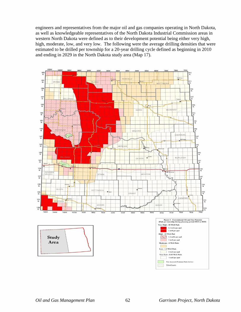
Oil and Gas Management Plan 62 Garrison Project, North Dakota
engineers and representatives from the major oil and gas companies operating in North Dakota, as well as knowledgeable representatives of the North Dakota Industrial Commission areas in western North Dakota were defined as to their development potential being either very high, high, moderate, low, and very low. The following were the average drilling densities that were estimated to be drilled per township for a 20-year drilling cycle defined as beginning in 2010 and ending in 2029 in the North Dakota study area (Map 17).

Oil and Gas Management Plan 63 Garrison Project, North Dakota
While most of the well spacing in the Bakken and Three Forks Formations is presently spaced at 1,280 acres, it is anticipated that these well spacings will eventually be downspaced to 640 acres, which will allow for more wells to be drilled. It is not anticipated that any new well spacing units will be lower than 640 acres, since horizontal drilling in the Bakken and Three Forks Formations is restricted to much wider spacing than the vertical wells drilled in the past. Based on these estimates it is projected that 8,460 wells would be drilled within the next 20 years in the western North Dakota study area (Elser et al., 2011; Stilwell et al., 2009). Using this same methodology it is estimated that a minimum of 63 new well pads containing a total of 92 wells will be drilled on the Garrison Project during this same time period. The high-end estimate is of 365 new well pads containing a total of 532 wells on the Garrison Project during the same 20-year time period.
9.1 Potential Future Surface Disturbance Table 2 projects short-term and long-term disturbance associated with the construction of between 63 – 365 new oil and gas wells and their ancillary facilities (e.g. new roads, pipelines, production tank installation, etc.) over the next 20 years. The method used to determine the number of new wells drilled during this period has been previously discussed. In addition, utilizing assumptions made by the BLM for potential future drilling activity in North Dakota (Elser et al., 2011; Stilwell et al., 2009) the success rate of new wells going into production will average 78%.
Table 2 - Short and Long Term Acres of Disturbance
Well Acres of Disturbance (Short Term)
Type Total Number of Wells
Ancillary Facilities
Well Pad Total Acreage
New Exploratory Oil and Gas Wells – Low Estimate (2010 – 2029)
63 2.9 4 444
New Exploratory Oil and Gas Wells – High Estimate (2010 – 2029)
365 2.9 4 2,519
Wells Acres of Disturbance (Long Term)
Type Total Number of Wells
Ancillary Facilities
Well Pad Total Acreage
New Producing Oil and Gas Wells – Low Estimate (2010 – 2029)
49 1.5 1.75 159
New Producing Oil and Gas Wells – High Estimate (2010 – 2029)
285 1.5 1.75 926
Oil and Gas Management Plan 64 Garrison Project, North Dakota
10.0 Mitigation Guidelines
10.1 Surface Disturbance Mitigation Guideline Under Army Regulation 405-30, the Garrison Project may require reasonable measures to minimize adverse impacts to other resource values, land uses, and users. Such reasonable measures or BMPs, may include, but are not limited to, modification of site location or design of facilities, timing of operations, and specification of interim and final reclamation measures, and prohibiting surface disturbance activities. The BMPs should be followed when developing an oil and gas project and are outlined in Appendix D.
Land under outgrant within the Garrison Project may include areas not specifically addressed by outgrant stipulations that may contain special values, may be needed for special purposes, or may require special attention to prevent damage to surface and/or other resources. Possible special areas are identified below. Any surface use or occupancy within such special areas will be strictly controlled or, if necessary, prohibited. Appropriate modifications to imposed restrictions would be made for the maintenance and operation of producing wells.
• Within 3,000 feet of critical flood protection infrastructure (i.e. dams, levees, etc.).
• Slopes in excess of 25 percent.
• Within important scenic areas (Class I and II Visual Resource Management Areas).
• Within 0.25 miles of surface water and/or riparian areas.
• Within either 0.25 miles or the visual horizon (whichever is closer) of any historic trails.
• Within 0.50 miles of occupied dwellings on or off the Garrison Project.
• Construction with frozen material or during periods when the soil material is saturated or when watershed damage is likely to occur.
10.1.1 Surface Disturbance Guidance The intent of the Surface Disturbance Mitigation Guideline is to inform interested parties (potential lessees, permittees, or operators) that when one or more of the above seven conditions exist, surface-disturbing activities will be prohibited until a permittee or his designated representative and the Garrison Project arrive at an acceptable plan for mitigation for anticipated impacts. This negotiation will occur prior to development. Specific criteria (e.g., 1,000 feet from water) have been established based upon the best information available. However, such items as geographical areas and seasons must be delineated at the field level. Exception, waiver, or modification of requirements developed from this guideline must be based upon environmental analysis of proposals (e.g., activity plans,
Oil and Gas Management Plan 65 Garrison Project, North Dakota
plans of development, plans of operation, and applications for permit to drill) and, if necessary, must allow for other mitigation to be applied on a site-specific basis. 10.2 Wildlife Mitigation Guideline To protect important big game winter habitat, activities or surface use will not be allowed from November 15 to April 30 within certain areas encompassed by the authorization. The same criteria apply to defined big game birthing areas from May 1 to June 30. Work that is proposed within these timeframes would have to undergo coordination with the Garrison Project, state natural resource agencies and the USFWS on a case-by-case basis.
• Application of this limitation to operation and maintenance of a developed project must
be based on environmental analysis of the operational or production aspects. • Exception, waiver, or modification of this limitation in any year may be approved in
writing, including documented supporting analysis, by the Operations Project Manager. To protect important raptor and/or sharp-tailed grouse nesting habitat, activities or surface use will not be allowed from February 1 to July 31 within certain areas encompassed by the authorization. The same criteria apply to defined raptor and game bird winter concentration areas from November 15 to April 1. Work that is proposed within these timeframes would have to undergo coordination with the Garrison Project, state natural resource agencies and the USFWS on a case-by-case basis.
• Application of this limitation to operation and maintenance of a developed project must be based on environmental analysis of the operational or production aspects.
• Exception, waiver, or modification of this limitation in any year may be approved in
writing, including documented supporting analysis, by the Authorized Officer.
No activities or surface use will be allowed on that portion of the authorization area identified for the purpose of protecting important wildlife habitat.
• Portions of the authorized use area described by the Corps as important wildlife habitat are known or suspected to be essential habitat for a species that is economically or culturally important, rare, threatened, or endangered.
• Prior to conducting any onsite activities, the lessee/permittee will be required to conduct
a Biological Assessment (BA) in accordance with Corps and USFWS laws and guidelines to verify the presence or absence of these species. The BA would be submitted to the USFWS for their opinion on affect determinations. In the event that the action may have adverse effects on a federally-listed or state concern species, the applicant would be required to adhere to any avoidance or mitigation measures outlined in the USFWS biological opinion. See Appendix C for guidelines on completing a biological assessment.
Oil and Gas Management Plan 66 Garrison Project, North Dakota
10.2.1 Wildlife Mitigation Guidance The Wildlife Mitigation Guideline is intended to provide two basic types of protection: seasonal restriction and prohibition of activities or surface use. For mitigation specific to situations involving threatened or endangered species see Section 10.5: No Surface Occupation Mitigation Guidance. Legal descriptions will ultimately be required and should be measurable and legally definable. There are no minimum subdivision requirements at this time. The area delineated can and should be defined as necessary, based upon current biological data, prior to the time of processing an application and issuing the use authorization. The legal description must eventually become a part of the condition for approval of the permit, plan of development, and/or other use authorization.
The seasonal restriction section identifies three example groups of species and delineates three similar time frame restrictions. The big game species including moose, deer, antelope, and bighorn sheep, all require protection of crucial winter range between November 15 and April 30. Bighorn sheep also require protection from disturbance from May 1 to June 30, when they typically occupy distinct calving and lambing areas. Raptors include eagles, accipiters, falcons (peregrine, prairie, and merlin), buteos (ferruginous and Swainson’s hawks), osprey, and burrowing owls. The raptors and sharp-tailed grouse require nesting protection between February 1 and July 31. The same birds often require protection from disturbance from November 15 through April 1 while they occupy winter concentration areas.
The prohibition of activity or surface use is intended for protection of specific wildlife habitat areas or values within the use area that cannot be protected by using seasonal restrictions. These areas or values must be factors that limit life-cycle activities (e.g., wetlands, sharp-tail grouse lek grounds, prairie dog towns, known threatened and endangered species habitat, etc.).
Exception, waiver, or modification of requirements developed from this guideline must be based upon environmental analysis of proposals (e.g., NEPA document, activity plans, plans of development, plans of operation, and applications for permit to drill) and, if necessary, must allow for other mitigation to be applied on a site-specific basis.
10.3 Cultural Resource Mitigation Guideline When a proposed discretionary land use has potential for affecting the characteristics which qualify a cultural property for the National Register of Historic Places (National Register), mitigation will be considered. In accordance with Section 106 of the National Historic Preservation Act, procedures specified in Title 36 CFR Part 800 will be used in consultation with the North Dakota State Historic Preservation Office and the Advisory Council on Historic Preservation in arriving at determinations regarding the need and type of mitigation to be required. Additional consultation with Tribal Governments may be required as described in 2.17.1 of the Garrison Dam/Lake Sakakawea Master Plan.
10.3.1 Cultural Resource Guidance The preferred strategy for treating potential adverse effects on cultural properties is “avoidance.” If avoidance involves project relocation, the new project area may also require cultural resource inventory. If avoidance is imprudent or unfeasible, appropriate mitigation may include excavation (data recovery), stabilization, monitoring, protection barriers and signs, or other physical and administrative measures.

Oil and Gas Management Plan 67 Garrison Project, North Dakota
Reports documenting results of cultural resource inventory, evaluation, and the establishment of mitigation alternatives (if necessary) shall be written according to standards of the Corps, the cultural resource permit stipulations, and in other policy issued by the Corps. These reports must provide sufficient information for Section 106 consultation. Reports shall be reviewed for adequacy by the appropriate Corps cultural resource specialist. If cultural properties on, or eligible for, the National Register are located within these areas of potential impact and cannot be avoided, the Garrison Project staff archaeologist shall begin the Section 106 consultation process in accordance with the procedures contained in 36 CFR 800. Mitigation measures shall be implemented according to the mitigation plan approved by the Corps’ Authorized Officer. Such plans are usually prepared by the land use applicant according to Corps specifications. Mitigation plans will be reviewed as part of Section 106 consultation for National Register eligible or listed properties. The extent and nature of recommended mitigation shall be commensurate with the significance of the cultural resource involved and the anticipated extent of damage. Reasonable costs for mitigation will be borne by the land use applicant. Mitigation must be cost effective and realistic. It must consider project requirements and limitations, input from concerned parties, and are Corps approved or Corps formulated. Mitigation of natural history sites will be treated on a case-by-case basis. Factors such as site significance, economics, safety, and project urgency must be taken into account when making a decision to mitigate. When avoidance is not possible, appropriate mitigation may include excavation (data recovery), stabilization, monitoring, protection barriers and signs, or other physical and administrative protection measures.
10.4 Special Resource Mitigation Guideline To protect special resources, activities or surface use will not be allowed (i.e., within a specific distance of the resource value or within a specific time span). Application of this limitation to operation and maintenance of a developed project must be based on environmental analysis of the operational or production aspects. Exception, waiver, or modification of this limitation in any year may be approved in writing, including documented supporting analysis, by the Corps’ Authorized Officer. Resource Categories:
• Recreation areas
• Special natural history or paleontological features
• Special management areas
• Prior existing rights-of-way
• Other as determined

Oil and Gas Management Plan 68 Garrison Project, North Dakota
10.4.1 Special Resource Guidance The Special Resource Mitigation Guideline is intended for use only in site-specific situations where one of the previous, or other three general mitigation guidelines will not adequately address the concern. The resource value, location, and specific restrictions must be clearly identified. A detailed plan addressing specific mitigation and special restrictions will be required prior to disturbance or development and will become a condition for approval of the permit, plan of development, or other use authorization. Exception, waiver, or modification of requirements developed from this guideline must be based upon environmental analysis of proposals (e.g., activity plans, plans of development, plans of operation, and applications for permit to drill) and, if necessary, must allow for other mitigation to be applied on a site-specific basis.
10.5 No Surface Occupancy Mitigation Guideline No Surface Occupancy (NSO) will be allowed on the following lands because of the potential impairment of the Garrison Project’s authorized purposes, conflict with environmental laws and regulations and potentially impacting cultural or Tribal resource sites. In addition to the NSO guidelines, construction restrictions based on critical fauna protection dates are outlined in Section 1.0 of Appendix D. The location of these areas may change; therefore, maps are available by request from the Garrison Project office.
• Within 0.50 miles of the established boundaries of developed recreation sites.
• Within 3,000 lateral feet of critical infrastructure (i.e. dams and levees). The depth of the exclusion zone extends approximately 3,950 miles beneath the surface of the Earth. The exclusion zone is a precautionary measure that would reduce the chances of oil and gas development-induced earthquakes from impacting critical flood control infrastructure that protects substantial lives and property.
• On islands located within the flood control pool for Lake Sakakawea, regardless of their elevation.
• Within the flood way or the 100-year floodplain.
• Prohibited on slopes greater than 25%.
• Within 0.25 miles on each side of the Little Missouri River (Scenic River) or less where Corps boundaries are not that wide.
• Within at least 300 feet of any National Register-eligible cultural site or American Indian Traditional Use Area.
• Within 0.50 miles of any piping plover or least tern nesting area.
• Within 0.50 miles (line of sight) of bald and golden eagle, marline, peregrine falcon and ferruginous hawk or other raptor nests.
Oil and Gas Management Plan 69 Garrison Project, North Dakota
• Within 0.50 miles (line of sight) of bald eagle winter roosting areas.
• Within 0.25 miles (line of sight) of prairie falcon and burrowing owl nests.
• Within 0.25 miles (line of sight) of a sharp-tailed grouse display ground.
• Special management area (e.g., known occupied threatened or endangered species critical habitat, areas along the Little Missouri River).
• Others as determined.
10.5.1 No Surface Occupancy Guidance The No Surface Occupancy (NSO) Mitigation Guideline is intended for use only when other mitigation is determined insufficient to adequately protect the public interest and is the only alternative to “no development” or “no leasing.” The legal description and resource value of concern must be identified and be tied to an NSO land use planning decision. Waiver of, or exception(s) to, the NSO requirement will be subject to the same test used to initially justify its imposition. If, upon evaluation of a site-specific proposal, it is found that less restrictive mitigation would adequately protect the public interest or value of concern, then a waiver or exception to the NSO requirement is possible. The record must show that because conditions or uses have changed, less restrictive requirements will protect the public interest. An environmental analysis must be conducted and documented (e.g., environmental assessment, environmental impact statement, etc., as necessary) in order to provide the basis for a waiver or exception to an NSO planning decision. Modification of the NSO requirement will pertain only to refinement or correction of the location(s) to which it applied. If the waiver, exception, or modification is found to be consistent with the intent of the planning decision, it may be granted. If the waiver is found inconsistent with the intent of the planning decision, a plan amendment would be required before the waiver, exception, or modification could be granted. When considering the “no development” or “no leasing” option, a rigorous test must be met and fully documented in the record. Since rejection of all development rights is more severe than the most restrictive mitigation requirement, the record must show that consideration was given to development subject to reasonable mitigation, including “no surface occupancy.” The record must also show that other mitigation was determined to be insufficient to adequately protect the public interest. A “no development” or “no leasing” decision should not be made solely because it appears that conventional methods of development would be unfeasible, especially where an NSO restriction may be acceptable to a potential permittee. In such cases, the potential permittee should have the opportunity to decide whether or not to go ahead with the proposal (or accept the use authorization), recognizing that an NSO restriction is involved. 11.0 Monitoring and Adaptive Management Effective management plan monitoring, whether it be for oil and gas exploration and development or land management, fosters adaptive management and more informed decision making. It helps identify the need to adjust desired conditions, goals, objectives, standards and guidelines as conditions change. Monitoring and evaluation of the O&GMP will help the Corps
Oil and Gas Management Plan 70 Garrison Project, North Dakota
and the public determine how the O&GMP is being implemented, whether O&GMP implementation is achieving desired outcomes, and whether assumptions made in the planning process are valid. Monitoring and evaluation are conducted at several scales and for many purposes, each of which has different objectives and requirements. Monitoring requirements and tasks are developed to be responsive to the objectives and scale of the plan or project to be monitored. Monitoring and evaluation are separate, sequential activities required to determine how well objectives have been met and how closely management guidelines have been applied. Monitoring generally includes the collection of data and information, either by observation or measurement. Evaluation is the analysis of the data and information collected during the monitoring phase. The evaluation results are used to determine the need to revise management plans, change how the plans are implemented, and form a basis for adaptively managing the Garrison Project. Monitoring and evaluation keeps the O&GMP up-to-date and responsive to changing issues by verifying the effectiveness of management plan guidelines and the anticipated oil and gas projects effects on resources and by providing information for updates to the O&GMP. As an adaptive management program, the Corps reserves the right to modify requirements as reasonable to address unintended or unforeseen negative effects of the activities. Results from monitoring or other additional information not available during the original permitting process shall be evaluated to determine adaptive alterations needed to limit resource damage or safety issues, and reasonable remedies shall be applied to alleviate excessive negative effects. In contrast, there may be instances where the project proponent may desire to expand operations outside of scope of the original permit or lessen required mitigation, and adaptive use of resource information may allow for this within reasonable limitation. 11.1 Implementation Monitoring – Projects and Programs
Implementation monitoring for projects and programs is applied mainly at an operational scale (i.e. site level) to assess the extent to which development activities comply with the O&GMP requirements and regulatory authorizations. The project proponent has a responsibility to ensure compliance with the O&GMP and with its permits to undertake activities. The Garrison Project has a responsibility to ensure compliance with permits and approved development plans. Exchanging information and coordination amongst various project proponents and the Corps may lead to reduced overall impacts; therefore project proponents operating in the same geographic area (e.g. same watershed) are strongly encouraged to coordinate their activities.
11.2 Mitigation Monitoring Measures Below is a summary of mitigation and monitoring that will be applied to oil and gas exploration and development projects to minimize adverse impacts or verify the presence, extent, or absence of anticipated impacts.
Each measure listed is briefly summarized and includes an identification of how application of the measure may influence project effects.
Oil and Gas Management Plan 71 Garrison Project, North Dakota
Mitigation measures fall within the actions the Corps can direct to prevent unnecessary or undue degradation of the public lands and protect surface resources in the approval of surface use plans. Mitigation, as defined by the CEQ in Title 40 – Protection of Environment, Code of Federal Regulations, Subsection 1608.20, may include one or more of the following:
• avoiding the impact altogether by not taking a certain action or parts of an action; • minimizing impacts by limiting the degree or magnitude of the action and its
implementation; • rectifying the impact by repairing, rehabilitating, or restoring the affected
environment; • reducing or eliminating the impact over time by preservation and maintenance
operations during the life of the action; and • compensating for the impact by replacing, or providing substitute resources or
environments.
All of the monitoring and management actions listed below will be required when oil and gas exploration and development projects are approved. In addition, the conditions of approval and best management practices listed in Appendix D will also be required as necessary on a site-specific basis.
11.2.1 Groundwater Resources The Corps is currently working on a groundwater sampling and analysis plan to ensure that drilling operations are safe and are not compromising the Garrison Project’s water quality. In the interim, a plan will be developed on a site-specific basis to address water quality concerns. Piezometers would be required to be installed at a minimum of two locations outside the limits of the project footprint. Ideally, these piezometers would be installed prior to any surface disturbing activities up and down gradient of fresh water bearing zones that the oil and gas well will penetrate. The Corps would sample the wells for common water quality parameters to establish a baseline for the project area. During well development (i.e. hydraulic fracturing processes) and during well production, the operator would be responsible for taking water quality samples and submitting, as part of the annual monitoring report, the results to the Garrison Project. Standard water quality sampling methodologies should be used including the use of blind duplicates to verify integrity of sample results. Water quality sampling protocols would be provided by the U.S. Army Corps of Engineers – Omaha District. Sampling and reporting would continue for the life of the well, or until the Garrison Project determines no effect to aquifers has occurred due to well development.

Oil and Gas Management Plan 72 Garrison Project, North Dakota
11.2.2 Surface Water Resources All project proponents will be required to monitor channel conditions within the area of project impact, including dry washes and other drainages, with photographic stations and/or other appropriate methods in coordination with the Garrison Project. All project proponents will be required to work cooperatively with the Corps, other federal, state and local governments, as well as public stakeholders to develop and implement an adaptive surface water management plan for the entire Garrison Project which could include the National Pollutant Discharge Elimination System (NPDES) process and consider runoff on a cumulative basis. All applicants will be required to comply with NWDR 1110-2-2.
11.2.3 Vegetation An interim and final reclamation plan will be submitted to the Garrison Project for approval prior to any surface disturbing activities. This plan would describe the following:
• The quantity and type of habitats that would be disturbed.
• Construction in native prairies will be avoided if at all possible.
• Any unavoidable losses of native forest or riparian forest shall be replaced with similar species in accordance with the Garrison Project Tree/Vegetation Mitigation Standard Operating Procedure #14. A monetary damage payment may be required in lieu of a mitigation planting.
• The applicant shall provide the Corps with a detailed wetland delineation, which shall be
performed prior to any disturbance in the immediate project area vicinity. This determination should follow the Corps’ Hydrogeomorphic Method (Smith et al. 1995). Based on information gathered from the wetland delineation, well sites will be located as far from sensitive wetlands as practicable. Placement of fill in wetlands will be avoided as much as possible. Unavoidable loss of wetland habitat will be replaced with functionally equivalent wetlands.
• Oil and gas pipelines should use directional drilling technology to traverse beneath sensitive
habit areas.
• The use of techniques other than grading should be considered (i.e. wood mats) for areas that would be temporarily impacted. If grading an entire pad is the only way to develop an oil and gas well, the logic should be included in the reclamation plan.
• How the well pad layout was designed to maximize interim reclamation.
• The proposed seed mix and application rates.
• Description of how seed would be applied (i.e. drilled, broadcast, etc.).
• Mulching requirements.

Oil and Gas Management Plan 73 Garrison Project, North Dakota
Monitoring to document reclamation success would be required and included as a part of a reclamation plan. General monitoring guidelines are outlined below:
• Monitoring would begin following the first growing season after seeding and continue for at
least two years.
• Performance standards would be developed on a site-specific basis and would have to be outlined in the monitoring plan and annual report.
• Adaptive management strategies may need to be implemented if reclamation efforts are not meeting performance standards.
• Monitoring should occur between June and August and reports should be submitted to the Garrison Project office by the end of December in any given year.
• Site visits with the Garrison Project staff may be required to validate monitoring report findings.
11.2.4 Wildlife All project proponents will be required to modify wildlife protection measures (e.g. altered buffer area sizes, seasonal restriction dates) based on the results of coordination with the USFWS and NDG&F, annual monitoring and/or other regional wildlife studies. All wildlife protection measures identified in the site specific NEPA document must be implemented as a part of the proposed project. All instances of fish or wildlife injury shall be reported to the Corps, USFWS and NDG&F. All project proponents would be encouraged to work cooperatively with the Corps, USFWS, and NDG&F to expand annual wildlife monitoring on the Garrison Project to include new wildlife and habitat study opportunities. All project proponents will be encouraged to develop or fund habitat enhancement projects on the Garrison Project to accommodate displaced wildlife.
11.2.5 Cultural and Tribal Resources All project proponents will be required to work cooperatively with the Corps through the Programmatic Agreement with the Missouri River Basin Tribes, THPO, and SHPO to develop and implement a research design, discovery plan and/or cultural resource management plan for the disturbed sites. 11.2.6 Livestock Grazing All project proponents will be required to work with affected livestock permittees to mitigate the loss of Animal Unit Months (AUMs) on the Garrison Project through provision of range improvement projects to modify grazing distribution patterns (e.g. water developments, vegetation treatments, irrigation, fencing, etc.) within the project-affected allotments.

Oil and Gas Management Plan 74 Garrison Project, North Dakota
11.2.7 Recreation All project proponents will be required to work cooperatively with the Corps, other federal, state and local governments, as well as public stakeholders to provide quality interpretive sites with public access and/or publications with public distribution to provide the general public and interested parties educational information regarding oil and gas development and management actions for other area-specific natural resource values. 11.2.8 Transportation All project proponents will jointly develop and submit to the Garrison Project approval road maintenance and use agreements designating road development, maintenance, and use requirements by each oil and gas exploration and development operator. These agreements will identify responsibilities for necessary preventive and corrective maintenance throughout impacted areas of the Garrison Project. Maintenance responsibilities could include, but are not limited to, blading, gravelling or aggregate-surfacing, cleaning ditches and drainage facilities, dust abatement, noxious weed control, culvert maintenance and repair, or other requirements. 11.2.9 Visual Resources Lake Sakakawea will be managed and maintained at a Bureau of Land Management (BLM) Visual Resource Management (VRM) II rating. The objective of a VRM II classification is to retain the existing character of the landscape, with the level of change being low to the characteristics of the landscape. Projects that may degrade Lake Sakakawea to a lower classification will not be allowed. All project proponents will share in the cost of hosting a visual resource management specialist or other such qualified consultant to work with the Garrison Project and oil and gas exploration and development operators to monitor and minimize visual effects. This position will be required until such time it is determined that both short- and long- term Visual Resource Management objectives would be accomplished. 11.2.10 Soil Resources All project proponents will be required to conduct site-specific pre-disturbance landscape descriptions, including soils data, plant species composition and cover data, to determine soil baseline, in order to aid in developing reclamation seed mixes specific to impacted sites. 11.2.11 Paleontology All project proponents will be required to participate in an active program of providing resources to inventory and evaluate sediments known or suspected to contain paleontological materials in order to better quantify cumulative impacts to the resource.
11.2.12 Other Actions All project proponents will share in the cost of hosting workers to the Garrison Project as needed to facilitate efficient and timely Corps permitting.

Oil and Gas Management Plan 75 Garrison Project, North Dakota
11.3 Adaptive Management Adaptive management is driven by the challenges faced in planning for oil and gas development in complex natural environments. This dynamic approach allows the Garrison Project to respond to inevitable unforeseen changes in social or environmental values or to new information from scientific studies, technology or oil and gas resource discoveries. Adaptive management, by its nature, recognizes this complexity, seeks innovative solutions and recognizes that current management decisions may result in less than ideal consequences. Overall, this approach intends to capitalize on learning from successes and mistakes in order to improve the overall management strategy. If the annual strategic monitoring review conducted by the Corps demonstrates that the monitored environmental metrics are not within acceptable/envisioned levels under this O&GMP then this plan could be re-visited and modified based on new information and/or changing environmental conditions. In pursuing this philosophy, the following outcomes would likely be achieved over time:
• continual improvement of the O&GMP and incorporation into the Master Plan for the Operation of the Garrison Project;
• improved oil and gas project development plans;
• informed collaboration amongst all parties;
• increased creativity and problem solving in addressing management direction issues;
• early detection of potential cumulative, long-term and large-scale effects of management approaches in regards to oil and gas exploration and development projects; and
• improved understanding and prediction of environmental responses to activities.
The Corps will assess the use of adaptive management in oil and gas development activities on the Garrison Project as part of an annual strategic monitoring review conducted by the Corps. 12.0 References Anderson, S. B., & Eastwood, W. P. (1968). Natural gas in North Dakota. In Natural gases in
rocks of Paleozoic Age (Memoir No. 9, Part 3, pp. 1304-1326). Tulsa, OK: American Association of Petroleum Geologists.
Baars, D. L., Watney, W. L., Steeples, D. W., & Brostuen, E. A. (1993). Petroleum: A primer
for Kansas. (Educational Series 7). Lawrence, KS: The University of Kansas, Kansas Geological Survey. Retrieved from http://www.kgs.ku.edu/Publications/Oil/index.html
Beck, B. (1992). The Mondakonians: Energizers of the prairie. Duluth, MN: Montana-Dakota Utilities Resources Group, Inc.
Oil and Gas Management Plan 76 Garrison Project, North Dakota
Braun, C. E., Baker, M. G., Eng, R. L., Gashwiler, J. S., & Schroeder, M. H. (1976).
Conservation committee report on the effects of alteration of sagebrush communities on the associated avifauna (The Wilson Bulletin Vol. 88, No. 1, pp. 165-171). Wilson Ornithological Society.
Canadian Centre for Energy Information. (2011). About energy: Oil and natural gas. Retrieved
from http://www.centreforenergy.com/AboutEnergy/ Clark, A. (2011, January 28). Producers turn to railroads for shipping Bakken crude.
Bloomberg News. Colorado Department of Public Health. (2009). Hazardous air pollutants from oil and gas
exploration and production. Retrieved from http://www.cdphe.state.co.us Crawford, E. (1999). Getting power to the people. The Forum. Retrieved from
http://legacy.inforum.com/specials/century/jan3/week8.htm Darin, T. F., & Stills, T. (2002). Preserving our public lands: A citizen’s guide to understanding
and participating in oil and gas decisions affecting our public lands. Boulder, CO: Land and Water Fund of the Rockies.
Division of Fisheries and Oceans Canada. (2004). Review of scientific information on impacts of
seismic sound on fish, invertebrates, marine turtles and marine mammals. (Habitat Status Report). Ottawa, Canada: Author.
Division of Fisheries and Oceans Canada. (1999). The possible impacts of petroleum
exploration activities on the Georges Bank ecosystem. (Canadian Technical Report of Fifth Series and Aquatic Sciences 2259). Ottawa, Canada: Author.
Dyer, S. J., O’Neill, J.P., Wasel, S. M., & Boutin, S. (2001). Avoidance of industrial
development by woodland caribou. Journal of Wildlife Management, 65(3), 531-542. Duncan Energy v. United States Forest Service, 50 F.3d 584, 591 (8th Cir. 1995). E&P Forum, & UNEP IE. (1997). Environmental management in oil and gas exploration and
production: An overview of issues and management approaches. Oxford, United Kingdom: Words and Publications.
Elser, A. M., Stilwell, D. P., & Davis-Lawrence, S. W. (2011). Revised activity and surface
disturbance projections for the development scenario for oil and gas activities on Bureau managed lands in the North Dakota study area. Casper, WY: U. S. Department of the Interior, Bureau of Land Management, Wyoming State Office Reservoir Management Group.
Enbridge set to expand North America’s crude oil pipeline network. (2010, September 1).

Oil and Gas Management Plan 77 Garrison Project, North Dakota
Pipelines International. Retrieved from http://pipelinesinternational.com/news/enbridge_set_to_expand_north_americas_crude_oil_pipeline_network/043516/#
Energy and Environmental Research Center. (2011). Bakken formation. Grand Forks, ND:
University of North Dakota, Energy and Environmental Research Center. Retrieved from http://www.undeerc.org/bakken/bakkenformation.aspx
Energy Policy Research Foundation, Inc. (2011). The Bakken boom: An introduction to North
Dakota’s shale oil. Washington, DC: Author. Fogleman, V. M. (1990). Guide to the National Environmental Policy Act: Interpretations,
applications, and compliance. Westport, CT: Quorum Books. Gibson, R. I. (1995). Basement tectonics and hydrocarbon production in the Williston Basin: An
interpretive overview. In 1995 Guidebook (pp. 3-11). Symposium conducted at the Seventh International Williston Basin Meeting.
Grape, S. G. (2006). Technology-based oil and natural gas plays: Shale shock! Could there be
billions in the Bakken? Washington, DC: U.S. Department of Energy, Energy Information Administration, Office of Oil and Gas, Reserves and Production Division. Retrieved from ftp://tonto.eia.doe.gov/features/ngshock.pdf
Heck, T. J., LeFever, R. D., Fischer, D. W., & LeFever, J. (2002). Overview of the petroleum
geology of the North Dakota Williston Basin. Bismarck, ND: North Dakota Geological Survey.
Helms, L. (2011). Director’s cut. Bismarck, ND: North Dakota Industrial Commission,
Department of Mineral Resources. Retrieved from https://www.dmr.nd.gov/oilgas/directorscut/directorscut-2011-08-17.pdf
Helms, L. (2011, January 7). North Dakota oil and gas. Presentation before the North Dakota
House Appropriations Committee. Retrieved from https://www.dmr.nd.gov/oilgas/presentations/HouseApprop2011-01-07.pdf
Interstate Oil and Gas Compact Commission. (2007). Improving access to onshore oil and gas
resources on federal lands. Pittsburgh, PA: U.S. Department of Energy, National Energy Technology Laboratory.
Interstate Oil and Gas Compact Commission. (1997). North Dakota state review: IOGCC/EPA
state review of oil & gas exploration and production waste management regulatory programs. Oklahoma City, OK: Author.
Krauss, C. (2011, September 27). In North Dakota, flames of wasted natural gas light the
prairie. The New York Times, p. A1. Retrieved from http://www.nytimes.com/2011/09/27/business/energy-environment/in-north-dakota-wasted-natural-gas-flickers-against-the-sky.html

Oil and Gas Management Plan 78 Garrison Project, North Dakota
Kringstad, J. J. (2010). An update on North Dakota’s natural gas infrastructure. Bismarck, ND:
North Dakota Pipeline Authority. LeFever, J. A., & Nordeng, S. H. (2008, June). Three Forks formation. North Dakota
Department of Mineral Resources Newsletter, 35(2), 4-5. Retrieved from https://www.dmr.nd.gov/ndgs/newsletter/nl0908/pdfs/threeforks.pdf
Lincoln, D. (2002). Sense and nonsense - The environmental impacts of exploration on marine organisms offshore Cape Breton. Paper submitted to the Public Review Commission for the Sierra Club Canada. Retrieved from http://www.sierraclub.ca/national/oil-and-gas-exploration/sense-and-nonsense.pdf
Macpherson, J. (2011, October 14). North Dakota likely to pass Calif. as oil producer this year.
Bloomberg BusinessWeek. Retrieved from http://www.businessweek.com/ap/financialnews/D9QCBMBO1.htm
Mall, A., Buccino, S., & Nichols, J. (2007). Drilling down – Protecting western communities
from the health and environmental effects of oil and gas production. Santa Monica, CA: Natural Resources Defense Council.
McCain and Associates, Inc. (2009). Environmental assessment for seven oil/gas wells, access
roads, and related infrastructure on the Fort Berthold Indian reservation: D-3 Brady #4-12H, D-3 Brunsell #16-9H, D-3 FBIR #3-13H, D-3 Mason #3-2H, D-3 North Segment #4-6H, D-3 Olson #4-1H, and D-3 Wolf #18-17H. Bismarck, ND: Author.
Michigan Environmental Science Board. (1997). Evaluation of directional drilling under the
Great Lakes. Lansing, MI: Author. Moss, K. (2008). Potential development of the natural gas resources in the Marcellus Shale –
New York, Pennsylvania, West Virginia, and Ohio. Denver, CO: National Park Service, Geologic Resources Division.
NaturalGas.org. (n.d.). Natural gas - From wellhead to burner tip. Retrieved from
http://www.naturalgas.org/naturalgas/naturalgas.asp Neset, R. (2009). Potential oil reserves of the lower Lodgepole Formation, Williston Basin
North Dakota. Minot, ND: Minot State University, Department of Geosciences. North Dakota Department of Mineral Resources. (n.d.). Well data website. Retrieved from
https://www.dmr.nd.gov North Dakota Petroleum Council. (n.d.). Royalty Owner Information Center. Retrieved from
http://www.ndoil.org/?id=130 North Dakota State University. (n.d.). Digital horizons – A plains media resource. (n.d.).

Oil and Gas Management Plan 79 Garrison Project, North Dakota
Retrieved from North Dakota State University, Institute for Regional Studies Web site: http://digitalhorizonsonline.org/index.php
North Dakota State University. (n.d.). Surface owner’s rights. Retrieved from
http://www.ag.ndsu.edu/NDOilandGasLaw/surfaceowners/surfaceownersrights North Dakota v. United States, 460 U.S. 300, 318, 75 L. Ed. 2d 77, 91 (1982). Onshore Oil and Gas Operations; Federal and Indian Oil and Gas Leases; Onshore Oil and Gas
Order Number 2, Drilling Operations, 43 C.F.R. pt. 3160 (1988). Retrieved from http://www.blm.gov/pgdata/etc/medialib/blm/mt/blm_programs/energy/oil_and_gas/operations/orders.Par.99392.File.dat/ord2.pdf
Onshore Oil and Gas Operations; Federal and Indian Oil and Gas Leases; Onshore Oil and Gas
Order Number 6, Hydrogen Sulfide Operations, 43 C.F.R. pt. 3160 (1991). Retrieved from http://www.blm.gov/pgdata/etc/medialib/blm/mt/blm_programs/energy/oil_and_gas/operations/orders.Par.25955.File.dat/ord6.pdf
Peterson, D. L. (2004). Seismic survey operations: Impacts on fish, fisheries, fishers and
aquaculture. Background briefing paper prepared for the British Columbia Seafood Alliance.
Pipkin, B. W., Trent, D. D., Hazlett, R., & Bierman, P. (2010). Geology and the environment
Florence, KY: Cengage Learning, Inc. Pollastro, R. M., Cook, T. A., Roberts, L. N. R., Schenk, C. J., Lewan, M. D., Anna, L. O.,
Gaswirth, S. B., Lillis, P. G., Klett, T. R., & Charpentier, R. R. (2008). Assessment of undiscovered oil resources in the Devonian-Mississippian Bakken formation, Williston Basin Province, Montana and North Dakota. (Fact Sheet, pp. 2008–3021). Washington, DC: U.S. Geological Survey.
Russell, J., & Pollack, A. (2005). Oil and gas emission inventories for the western states. Final
report prepared for the Western Governor’s Association, Denver, CO. Retrieved from http://www.wrapair.org/forums/ssjf/documents/eictts/OilGas/WRAP_Oil&Gas_Final_Report.122805.pdf
Schramm, J. (2011, October 18). The Bakken boom: Rail terminal construction picking up
speed. Minot Daily News. Retrieved from http://www.minotdailynews.com/page/content.detail/id/559554/The-Bakken-boom--Rail-terminal-construction-picking-up-speed
Science Applications International Corporation. (1992). Background for NEPA reviewers:
Crude oil and natural gas exploration, development, and production. Falls Church, VA: Environmental and Health Sciences Group.
Stilwell, D. P., Elser, A. M., & Davis-Lawrence, S. W. (2009). Reasonable foreseeable

Oil and Gas Management Plan 80 Garrison Project, North Dakota
development scenario for oil and gas activities on Bureau managed lands in the North Dakota study area. Casper, WY: U.S. Department of the Interior, Bureau of Land Management, Wyoming State Office Reservoir Management Group.
Strong, L. L. (2005). North Dakota gap analysis project. (Gap Analysis Bulletin No. 13).
Retrieved from http://www.gap.uidaho.edu/bulletins/13/North_Dakota.htm Sumi, L. (2005). Oil and gas at your door? A landowner’s guide to oil and gas development.
Durango, CO: Oil and Gas Accountability Project. SWCA Environmental Consultants. (2006). Jonah infill drilling project development
procedures technical support document. Phoenix, AZ: Author. Trombulak, S. C., & Frissell, C. A. (2000). Review of ecological effects of roads on
terrestrial and aquatic communities. Conservation Biology, 14(1), 118-130. U.S. Army Corps of Engineers. (2007). Garrison Dam/Lake Sakakawea master plan with
integrated programmatic environmental assessment Missouri River, North Dakota. (Update of Design Memorandum MGR-107D). Omaha, NE: Author.
U.S. Army Corps of Engineers. (2005). Known and potential environmental effects of oil and
gas drilling activity in the Great Lakes – A report to Congress. Chicago, IL: Author. U.S. Bureau of Land Management. (2006). Roan Plateau resource management plan
amendment and final environmental impact statement. Glenwood Springs, CO: Author. U.S. Bureau of Land Management. (2003). Farmington resource management plan with record
of decision. Farmington, NM: Author. Retrieved from http://www.blm.gov/pgdata/etc/medialib/blm/nm/field_offices/farmington/farmington_planning/ffo_rmp_docs.Par.32114.File.dat/Final%20RMP%20with%20ROD.pdf
U.S. Bureau of Land Management, & U.S. Forest Service. (2001). Off-highway vehicle final
environmental impact statement and proposed plan amendment for Montana, North Dakota and portions of South Dakota. Washington, DC: Authors. Retrieved from http://www.blm.gov/pgdata/etc/medialib/blm/mt/blm_programs/recreation/ohv_eis.Par.42745.File.dat/preface.pdf
U.S. Department of Energy. (2009). Modern shale gas development in the United States:
A primer. Pittsburgh, PA: Office of Fossil Energy and National Energy Technology Laboratory.
U.S. Environmental Protection Agency. (2000). Profile of the oil and gas extraction industry.
(EPA Office of Compliance Sector Notebook Project, EPA/310-R-99-006). U.S. Fish and Wildlife Service. (2000). Potential impacts of proposed oil and gas
development on the Arctic Refuge’s coastal plain: Historical overview and issues of concern. Retrieved from http://arcticcircle.uconn.edu/ANWR/anwr_fws.htm

Oil and Gas Management Plan 81 Garrison Project, North Dakota
U.S. Forest Service. (2001). Environmental impact statement and record of decision - Finger
Lakes National Forest oil and gas leasing. Hector, NY: Author. Webster, R. L. (1992). Petroleum source rocks and stratigraphy of the Bakken Formation in
North Dakota. In J. M. Erickson & J.W. Hoganson (Eds.), North Dakota Geological Survey Miscellaneous Series No. 76 (pp. 149-178). Proceedings of the F.D. Holland, Jr. Geological Symposium.
Yukon Government. (2006). Oil and gas best management practices – Seismic exploration.
Whitehorse, Canada: Energy Mines and Resources, Oil and Gas Management Branch.

This space left blank intentionally.
APPENDIX A
Application Information for
Proposed Projects on Corps of Engineers Land

This space left blank intentionally.

Application Information for Proposed Projects on
Corps of Engineers Land
Table of Contents SECTION 1: General Outgrant Application Information ................................................................................. 1
SECTION 2: Mitigation Guidance ................................................................................................................... 4
SECTION 3: Additional Guidance for Specific Outgrant Applications ........................................................... 8
SECTION 4: Applications for Permit to Drill on the Garrison Dam/Lake Sakakawea Project ..................... 11

P a g e | 1
Appendix A Oil and Gas Management Plan Garrison Project, ND
SECTION 1: General Outgrant Application Information
1. Preliminary information submittal - The applicant must provide the preliminary information requested below (a-i) to the Corps of Engineers, Omaha District (Corps) Project Level Representative. The initial submission will be evaluated by the Project Level Representative and Corps District team to determine if a proposal is appropriate for location on Government property. Administrative cost for the evaluation of any application documents (preliminary, detailed, supporting) will be paid by the applicant prior to the start (up front) of the review process by Project and District personnel, in accordance with Civil Works Policy Memorandum, "Collection of Civil Works Appropriations" dated 2 October, 2008.
a. Identify Applicant: (1) Name, address, phone number, and email address of applicant. The application must
be submitted by the entity to whom the outgrant will be assigned.
(2) Point of contact for processing (e.g. Engineering Firm, City Manager, Mayor, Commissioner, if agent, extent of authority to represent applicant, etc)
b. Describe the structure or facility.
c. Identify the purpose, need and objective (benefits, enhancements, statutory requirements)
for the structure or facility.
d. Justify placement of structure or facility on government property. The justification should include a description of all alternative locations and routes that were investigated, including routes and locations off of project lands. The description will also include rationale for why the other alternatives were not selected. An applicant must prove technological constraints (i.e. limits of horizontal wells) would prevent development of oil and gas wells off of Project lands. Corps’ Projects manage lands directly adjacent to surface waters because of the higher probability that they may be flooded. Flooded oil and gas wells pose a significant risk to numerous resources and authorized purposes of federally managed water sources. Cost alone will not affect the determination of viability of alternative locations.
e. State the duration for which the proposed outgrant is requested. Include the duration of
the temporary constuction license if one is needed (usually 1 year).
f. Specifically describe the location and dimensions of the requested outgrant area to include a preliminary site plan. NOTE: Outgrants should be placed in the footprint of existing project outgrants or within designated corridors where possible. Roads, pipelines or any other attendant features to the well pad should be located, if practicable, within previously disturbed locations.
g. Provide basic construction methods and timeline.

P a g e | 2
Appendix A Oil and Gas Management Plan Garrison Project, ND
h. Anticipated impacts (environmental, cultural resource, social, etc.).
i. Identify any other federal agency or public lands involved.
2. Detailed information submittal - If upon review of an initial request, the Corps determines that the requested activity may be feasible and will be considered further, the information below must be provided as required. This information will be provided to the Project Level Representative and be evaluated by the Corps Omaha District team. Additional information may be requested based on the nature of the proposed activity. A Corps determination will be made as to what type of environmental analysis would be required for the proposed action. Preliminary information concerning administrative fees, consideration and mitigation will be provided to the applicant.
a. Coordination
(1) Provide concurrence from third parties who may be affected by the structure or facility. (e.g. other existing outgrants)
(2) Provide other agency concurrence regarding legal or regulatory requirements where necessary (e.g. responsible State natural resources and utility entities).
(3) Explore opportunities for applicant or jointly-funded studies to expedite processing.
Studies will be done per Corps requirements and standards. (4) Identify authorized uses for this project (temporary and long term). Determine if other
uses or mining claims may conflict with the proposal. (5) Complete all coordination as required by the National Environmental Policy Act of
1969 (NEPA). NOTE - A temporary real estate instrument will be required prior to conducting any on-the ground activities (for environmental surveys, ground disturbance, soil and groundwater testing). An Archeological Resources Protection Act (ARPA) permit may also be required.
b. Description of Proposal
(1) Provide preliminary plans and specifications for the proposed out grant (engineering,
project area, equipment storage. Include construction areas, if applicable.
(2) Provide a map(s) which includes the following:
(a) A Public Land and Survey System legal description (location, identification of parcel, includes mineral interest information) of the proposal. (reference to a known Corps of Engineers property monument is encouraged), This description can also be provided separately; (GIS Shape Files (NAD 83), along with hard
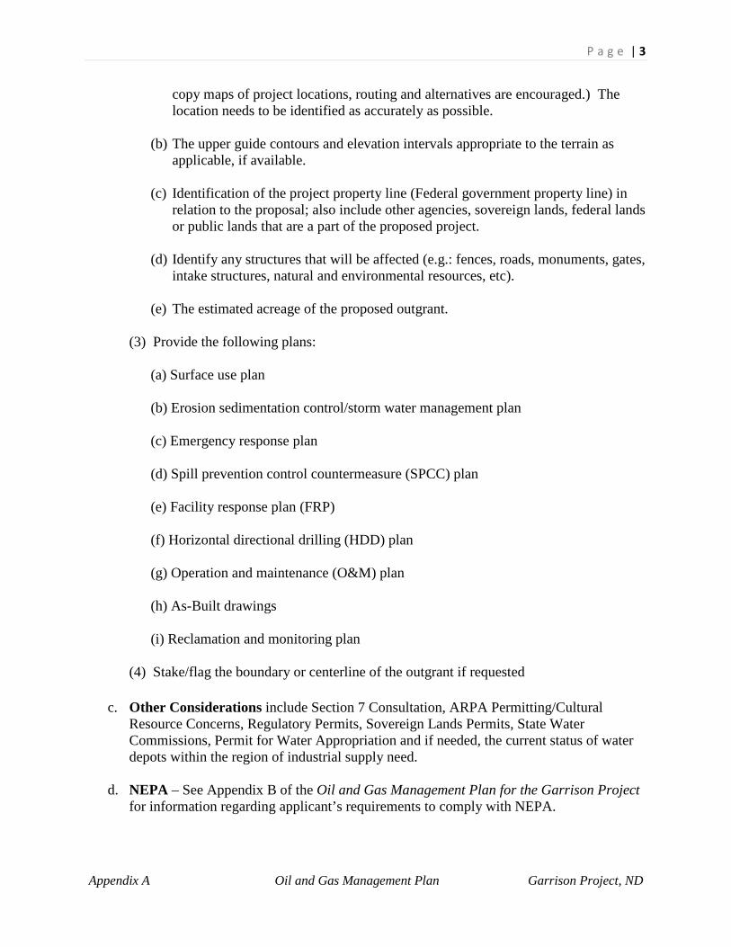
P a g e | 3
Appendix A Oil and Gas Management Plan Garrison Project, ND
copy maps of project locations, routing and alternatives are encouraged.) The location needs to be identified as accurately as possible.
(b) The upper guide contours and elevation intervals appropriate to the terrain as applicable, if available.
(c) Identification of the project property line (Federal government property line) in
relation to the proposal; also include other agencies, sovereign lands, federal lands or public lands that are a part of the proposed project.
(d) Identify any structures that will be affected (e.g.: fences, roads, monuments, gates,
intake structures, natural and environmental resources, etc).
(e) The estimated acreage of the proposed outgrant.
(3) Provide the following plans:
(a) Surface use plan (b) Erosion sedimentation control/storm water management plan (c) Emergency response plan (d) Spill prevention control countermeasure (SPCC) plan (e) Facility response plan (FRP) (f) Horizontal directional drilling (HDD) plan (g) Operation and maintenance (O&M) plan (h) As-Built drawings (i) Reclamation and monitoring plan
(4) Stake/flag the boundary or centerline of the outgrant if requested
c. Other Considerations include Section 7 Consultation, ARPA Permitting/Cultural Resource Concerns, Regulatory Permits, Sovereign Lands Permits, State Water Commissions, Permit for Water Appropriation and if needed, the current status of water depots within the region of industrial supply need.
d. NEPA – See Appendix B of the Oil and Gas Management Plan for the Garrison Project for information regarding applicant’s requirements to comply with NEPA.

P a g e | 4
Appendix A Oil and Gas Management Plan Garrison Project, ND
e. Mitigation - Non-statutory mitigation is generally required for impacted public resources. Mitigation often requires, but is not limited to, wildlife habitat improvement and vegetative plantings on the area of actual disturbance and on additional areas or other forms of restitution. Statutory mitigation may also be required if the proposed work involves applicable statutes, regulations, and guidance concerning impacts of a proposed action. For example, a discharge of dredged or fill material into waters of the U.S. typically requires a Section 404 permit (Clean Water Act) and associated mitigation. See Section 2 below and Appendix B for more mitigation guidance.
f. Storm Water Requirements - In accordance with State, County and/or local laws, various Districts within the Corps do not allow outgrants for storm water facilities. For those Districts that allow outgrants for storm water facilities, the applicant must also contact the applicable State, County and/or local agency responsible for storm water permits. The applicant must provide documentation of the contact, a Notice of Intent and evidence that a permit is being pursued (if required). In addition, the applicant shall provide a Storm Water Pollution Prevention Plan when required if earth-disturbing activities are to be performed. This plan shall include the means by which erosion and sedimentation will be controlled and monitored to protect the drainage courses.
g. Storage Capacity - In general, Corps policy is no net loss of maximum storage capacity. This typically includes calculating amounts of cut and fill, which could impact storage capacity.
h. Landscaping and Revegetation - As part of site stabilization and restoration, the applicant in most cases will be required to reestablish vegetation after construction. The applicant must demonstrate that the seed and vegetative plantings proposed for revegetation are native species to the area and not listed as an invasive species on a Federal or applicable State list. The seed mixture should be submitted to the Project and approved before using.
NOTE: Applicants, please review Section 3 for guidance addressing additional requirements for specific types of outgrants.
SECTION 2: Mitigation Guidance
1. Statutory Mitigation. Statutory mitigation must be done in accordance with applicable statutes, regulations and guidance. Statutory mitigation is generally defined as actions that reduce the severity or intensity of adverse impacts of other actions, to include:
a. Avoiding the impact by not taking a certain action or parts of an action or by moving the project location. Applicants are encouraged to consider avoidance as the preferred mitigation measure.
b. Minimizing impacts by limiting the degree or magnitude of the action and its implementation, for example, by adjusting site layout.

P a g e | 5
Appendix A Oil and Gas Management Plan Garrison Project, ND
c. Rectifying the impact by repairing, rehabilitating, relocating, or restoring the affected
public resources.
d. Reducing or eliminating the impact over time by monitoring, maintaining, and/or replacing equipment or structures to prevent future degradation from equipment or structural failure over the life of the action.
e. Compensating for the impact by replacing or providing substitute resources or
environments. With the exception of unique habitats under imminent threat of destruction, a mere change in ownership of existing habitat is generally not considered mitigation. Habitat improvement must be implemented in addition to long-term protection of the habitat.
Statutory Mitigation requirements vary somewhat under the environmental laws, regulations, and executive orders. For Corps of Engineers Regulatory Program mitigation guidance refer to 40 CFR Part 230 "Compensatory Mitigation for Losses of Aquatic Resources", 33 CFR 320.4 paragraph R, and 33 CFR 332. It is recommended that for actions on Civil Works lands and waters that require mitigation under these regulations, the mitigation occur on site where feasible. 2. Non-Statutory Mitigation: The definition of mitigation is broadened to include "all measures necessary to make the Corps project whole". Not all of the adverse impacts to a site will be required to be mitigated by a federal statute or regulation, but for outgrants, all adverse impacts must be mitigated unless a waiver is issued (see paragraph 4). The applicant for the outgrant will be advised of the impact and required mitigation. An example of impacts that may not be covered by existing authorities is a proposal that is categorically excluded from NEPA documentation but may still result in the destruction of a small wooded area containing twenty trees. There are no threatened or endangered species or any wetlands involved. Another instance may entail the destruction of 20 campsites resulting from a road expansion. In each case, the impacted resources must be restored or otherwise mitigated. 3. Real Estate Outgrant Documentation.
a. Where mitigation is required as a result of an outgrant, it will be addressed as a condition of the real estate instrument. A copy of the mitigation plan, use restrictions, and/or Memorandum of Agreement (MOA) will be included as an attachment to the outgrant document. If a mitigation plan, restrictions or an MOA is required, the outgrant instrument must be modified to incorporate compliance with the terms of the plan, restrictions or MOA as a condition of the outgrant. The outgrant instrument must be modified to incorporate a specific termination clause to address failure to comply with mitigation requirements.
b. In addition, action may also be required under the specific statute(s) that required the mitigation. A clear timetable must also be provided if mitigation requirements extend beyond the execution date of the outgrant agreement. Coordination with the office(s)
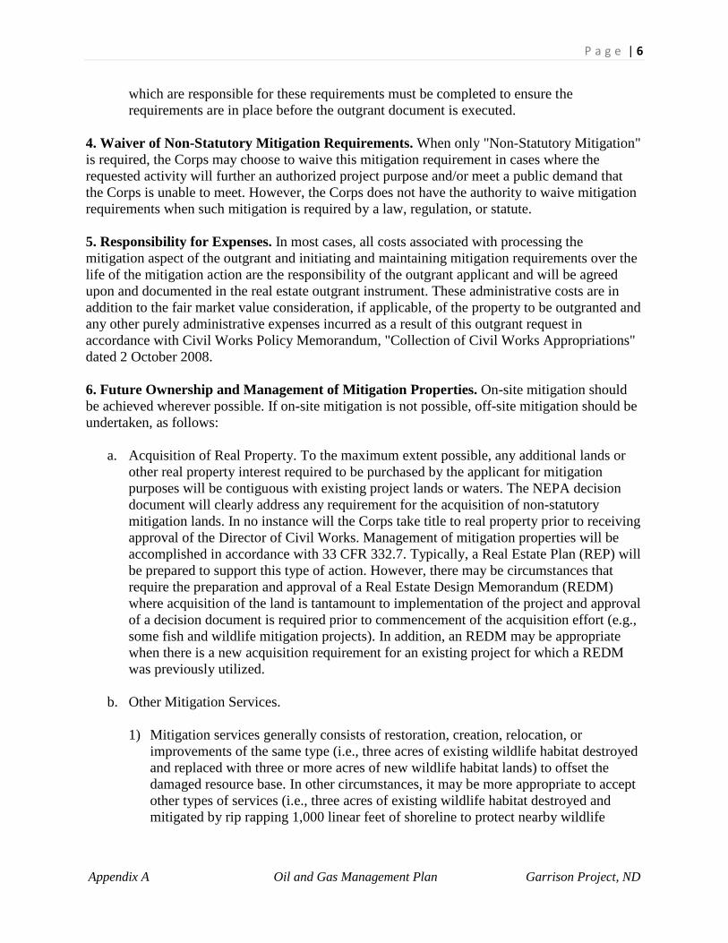
P a g e | 6
Appendix A Oil and Gas Management Plan Garrison Project, ND
which are responsible for these requirements must be completed to ensure the requirements are in place before the outgrant document is executed.
4. Waiver of Non-Statutory Mitigation Requirements. When only "Non-Statutory Mitigation" is required, the Corps may choose to waive this mitigation requirement in cases where the requested activity will further an authorized project purpose and/or meet a public demand that the Corps is unable to meet. However, the Corps does not have the authority to waive mitigation requirements when such mitigation is required by a law, regulation, or statute. 5. Responsibility for Expenses. In most cases, all costs associated with processing the mitigation aspect of the outgrant and initiating and maintaining mitigation requirements over the life of the mitigation action are the responsibility of the outgrant applicant and will be agreed upon and documented in the real estate outgrant instrument. These administrative costs are in addition to the fair market value consideration, if applicable, of the property to be outgranted and any other purely administrative expenses incurred as a result of this outgrant request in accordance with Civil Works Policy Memorandum, "Collection of Civil Works Appropriations" dated 2 October 2008. 6. Future Ownership and Management of Mitigation Properties. On-site mitigation should be achieved wherever possible. If on-site mitigation is not possible, off-site mitigation should be undertaken, as follows:
a. Acquisition of Real Property. To the maximum extent possible, any additional lands or other real property interest required to be purchased by the applicant for mitigation purposes will be contiguous with existing project lands or waters. The NEPA decision document will clearly address any requirement for the acquisition of non-statutory mitigation lands. In no instance will the Corps take title to real property prior to receiving approval of the Director of Civil Works. Management of mitigation properties will be accomplished in accordance with 33 CFR 332.7. Typically, a Real Estate Plan (REP) will be prepared to support this type of action. However, there may be circumstances that require the preparation and approval of a Real Estate Design Memorandum (REDM) where acquisition of the land is tantamount to implementation of the project and approval of a decision document is required prior to commencement of the acquisition effort (e.g., some fish and wildlife mitigation projects). In addition, an REDM may be appropriate when there is a new acquisition requirement for an existing project for which a REDM was previously utilized.
b. Other Mitigation Services. 1) Mitigation services generally consists of restoration, creation, relocation, or
improvements of the same type (i.e., three acres of existing wildlife habitat destroyed and replaced with three or more acres of new wildlife habitat lands) to offset the damaged resource base. In other circumstances, it may be more appropriate to accept other types of services (i.e., three acres of existing wildlife habitat destroyed and mitigated by rip rapping 1,000 linear feet of shoreline to protect nearby wildlife
P a g e | 7
Appendix A Oil and Gas Management Plan Garrison Project, ND
habitat). Entering into agreements for the replacement of impacted wildlife habitat with recreation facilities is generally not appropriate.
2) In the absence of specific authority, the Corps may not accept cash in lieu of mitigation services. In some limited instances, however, it is possible for the Corps to directly perform the mitigation work by entering into agreements with states or others and then to be reimbursed by the state or others for such work. Approval from the Assistant Secretary of the Army (Civil Works) (ASA-CW) may be necessary prior to entering into such an agreement. In some cases, a real estate instrument or a management plan may be required in accordance with 33 CFR 332.7 if a land acquisition is part of the mitigation service.
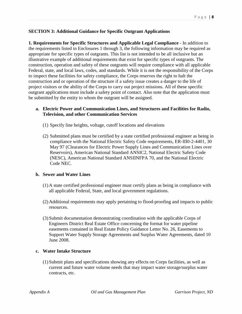
P a g e | 8
Appendix A Oil and Gas Management Plan Garrison Project, ND
SECTION 3: Additional Guidance for Specific Outgrant Applications
1. Requirements for Specific Structures and Applicable Legal Compliance - In addition to the requirements listed in Enclosures 1 through 3, the following information may be required as appropriate for specific types of outgrants. This list is not intended to be all inclusive but an illustrative example of additional requirements that exist for specific types of outgrants. The construction, operation and safety of these outgrants will require compliance with all applicable Federal, state, and local laws, codes, and standards. While it is not the responsibility of the Corps to inspect these facilities for safety compliance, the Corps reserves the right to halt the construction and or operation of the structure if a safety issue creates a danger to the life of project visitors or the ability of the Corps to carry out project missions. All of these specific outgrant applications must include a safety point of contact. Also note that the application must be submitted by the entity to whom the outgrant will be assigned.
a. Electric Power and Communication Lines, and Structures and Facilities for Radio, Television, and other Communication Services
(1) Specify line heights, voltage, cutoff locations and elevations (2) Submitted plans must be certified by a state certified professional engineer as being in
compliance with the National Electric Safety Code requirements, ER-III0-2-4401, 30 May 97 (Clearances for Electric Power Supply Lines and Communication Lines over Reservoirs), American National Standard ANSIC2, National Electric Safety Code (NESC), American National Standard ANSIINFPA 70, and the National Electric Code NEC.
b. Sewer and Water Lines
(1) A state certified professional engineer must certify plans as being in compliance with
all applicable Federal, State, and local government regulations.
(2) Additional requirements may apply pertaining to flood-proofing and impacts to public resources.
(3) Submit documentation demonstrating coordination with the applicable Corps of
Engineers District Real Estate Office concerning the format for water pipeline easements contained in Real Estate Policy Guidance Letter No. 26, Easements to Support Water Supply Storage Agreements and Surplus Water Agreements, dated 10 June 2008.
c. Water Intake Structure (1) Submit plans and specifications showing any effects on Corps facilities, as well as
current and future water volume needs that may impact water storage/surplus water contracts, etc.

P a g e | 9
Appendix A Oil and Gas Management Plan Garrison Project, ND
(2) Submit documentation demonstrating coordination with the applicable Corps of Engineers District Real Estate Office concerning requirements contained in Real Estate Policy Guidance Letter No. 26, Easements to Support Water Supply Storage Agreements and Surplus Water Agreements, 10 June 2008.
(3) Provide written documentation showing permission has been procured from the water
contract holder if required.
(4) Provide approval/permit from appropriate regulatory agency (state/local) if applicable. Also provide water supply contract, authorizing document, or decision document based on statute, for authorizing a water supply intake.
(5) Provide documentation of review and approval from Corps of Engineers Dam Safety
Committee
d. Outfalls (e.g. stormwater, sewage, etc.) (1) A copy of the National Pollutant Discharge Elimination System (NPDES) permit must
be provided for approval of any outfall that is placed on Corps administered lands and waters. Also furnish any other state/local approvals as applicable.
(2) A plan to prevent erosion and to prevent litter, trash, and pollutants from being deposited on Corps administered lands and waters must be provided.
(3) Submitted plans must be certified by a state certified professional engineer. (4) Submitted plans must be in compliance with Project Shoreline Management Plan if
applicable.
e. Major Oil, Natural Gas and Fuel Carrying Pipelines (Under USC 30 Section 185 for pipelines 24"and greater in diameter)
(1) Disclosure of Ownership - If a partnership, corporation, association, or other business
entity applies for an easement, the application shall disclose, where applicable: (a) Name and address of each partner (b) Name and address of each shareholder owning 3 percent or more of the shares; the number and percentage of any class of voting shares of the entity; and
(c) Name and address of each affiliate of the entity. If the entity controls the affiliate, include the number of shares and percentage of any class of voting stock of that affiliate; if, however, the affiliate controls the entity, include the number of shares and percentage of any class of voting stock of the entity.
(2) If this information is already on file, and current, in the District Engineer's office, or
local Bureau of Land Management or Federal Energy Regulatory Commission offices, references may be made to it; the applicant need not file repetitious disclosure documents with successive applications.

P a g e | 10
Appendix A Oil and Gas Management Plan Garrison Project, ND
(3) Submit documentation demonstrating coordination with the applicable Corps of
Engineers District Real Estate Office concerning requirements contained in Real Estate Policy Guidance Letter No. 27, Issuance of Fuel Carrying Pipelines that are 24 inches or more in diameter, 29 October 2008.
NOTE: For oil, natural gas and fuel pipelines smaller than 24" in diameter, please refer to
requirements contained in General Outgrant Application Information (Enclosure 1).
f. Roads
(1) Generally, Civil Works lands will only be made available for roads that are considered regional arteries or freeways (See Definitions in the Guidance). All other types of roads, including driveways and alleys, are generally not permitted on these lands. The expansion of existing roads on Civil Works lands will be considered on a case by case basis.
(2) Indicate whether or not Federal Highway Administration funds are being used for this road.
(3) A state certified professional engineer must certify plans as being in compliance with all applicable Federal, State, and local government Regulations.
g. Telecommunications. Authorities applicable to issuing outgrants for telecommunication purposes depending on the type of instruments desired are referenced in the Telecommunications Act of 1996, which is codified at 47 USC 332 and implementing regulations are provided in 41 CFR 102-79.70 to 79.100. In addition the applications must be in compliance with forthcoming Engineering Circular 405-1-80 (Management and Outgrant Programs), Section XIX, Procedures for Sitting of Communications Facilities on Army Controlled Lands. Proposals must include documentation to ensure the outgrant would not create the following problems:
(1) Impair, interfere, or degrade the Federal missions of the project or its operations. (2) Interfere with existing radio frequency (RF) activities. (3) Documentation of coordination with Federal Aviation Administration (FAA) and/or
Department of Defense (DoD) and sitting approval for any proposed telecommunication facility that will be located within proximity to an existing FAA facility or DoD system.
h. Hydropower facilities. Any request to construct/develop hydropower facilities will be an
unusual request that will be handled on a case by case basis per ER 1110-2-1454 as amended.
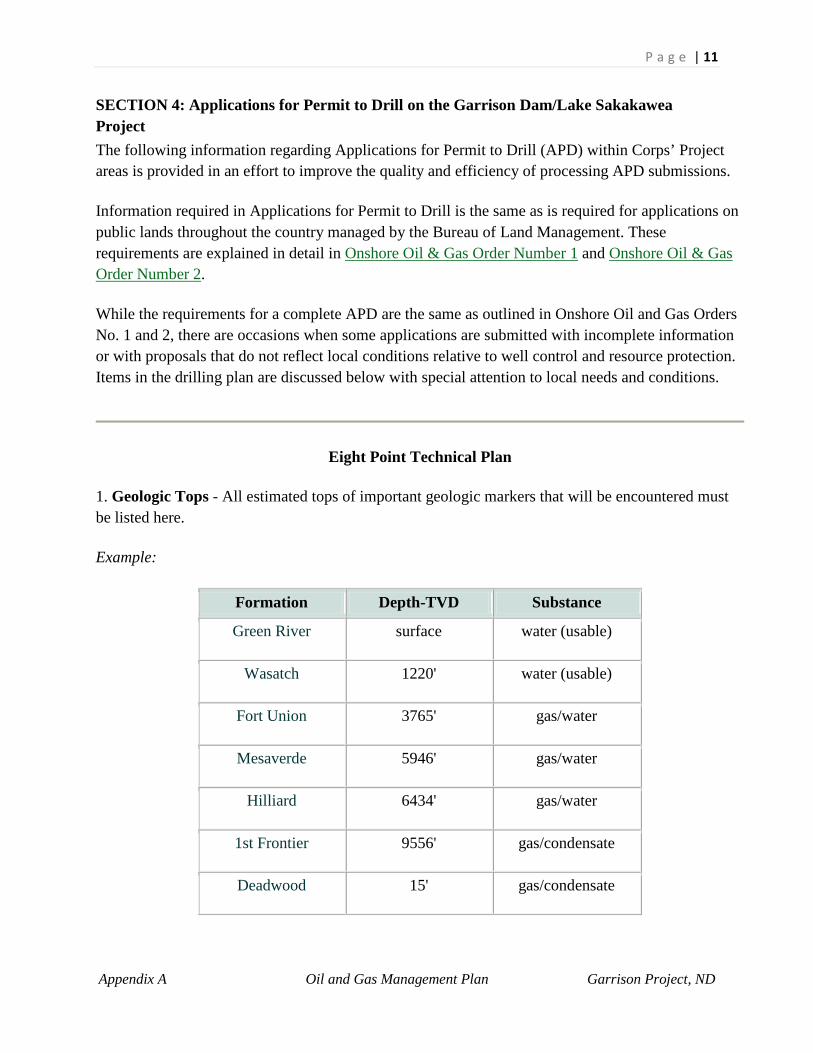
P a g e | 11
Appendix A Oil and Gas Management Plan Garrison Project, ND
SECTION 4: Applications for Permit to Drill on the Garrison Dam/Lake Sakakawea Project The following information regarding Applications for Permit to Drill (APD) within Corps’ Project areas is provided in an effort to improve the quality and efficiency of processing APD submissions.
Information required in Applications for Permit to Drill is the same as is required for applications on public lands throughout the country managed by the Bureau of Land Management. These requirements are explained in detail in Onshore Oil & Gas Order Number 1 and Onshore Oil & Gas Order Number 2.
While the requirements for a complete APD are the same as outlined in Onshore Oil and Gas Orders No. 1 and 2, there are occasions when some applications are submitted with incomplete information or with proposals that do not reflect local conditions relative to well control and resource protection. Items in the drilling plan are discussed below with special attention to local needs and conditions.
Eight Point Technical Plan
1. Geologic Tops - All estimated tops of important geologic markers that will be encountered must be listed here.
Example:
Formation Depth-TVD Substance
Green River surface water (usable)
Wasatch 1220' water (usable)
Fort Union 3765' gas/water
Mesaverde 5946' gas/water
Hilliard 6434' gas/water
1st Frontier 9556' gas/condensate
Deadwood 15' gas/condensate

P a g e | 12
Appendix A Oil and Gas Management Plan Garrison Project, ND
Mowry 11294' some water, oil/gas
Dakota 11691' oil/gas
2. Estimated depths of anticipated oil, gas, water, or mineral bearing formations - This information is important (see Example above). Oil and gas operators must design the casing and cementing program to protect all mineral zones and design the cementing program to protect usable water (less than 10,000 ppm TDS) from commingling with brackish water or hydrocarbons. This can be done by casing over the usable water entirely or by circulating cement above all oil and gas or brackish water zones.
3. Pressure control equipment - A diagram of the proposed BOP (blowout pressure) stack and choke manifold must be included showing sizes, pressure ratings (or API series), testing procedures, and the testing frequency. The working pressure of the BOP stack will be calculated by assuming a partially evacuated hole with a fluid column in the hole equivalent to 4.23 ppg (.22 psi/ft).
Example:
• Total Depth = 12,000 ft. • Bottom Hole Pressure = 6,480 psi. • Minimum BOP Working Pressure = 6,480 psi - .22 psi/ft * 12,000 ft = 3,840 psi • BOPE of 5,000 psi (5M) working pressure is required.
4. Complete information on the drilling equipment, casing and cementing program - The proposed casing program shall include the size, weight, grade, and length of casing proposed, type of thread and coupling, and setting depth of each string, and whether it is new or used. Although not required, some operators also provide the burst, collapse, and tensile strength of the proposed casing. It is also helpful to show the casing design factors used and any assumptions made with regard to formation and fracturing pressures.
The cementing program must include the type of cement to be used on all strings of casing. It should include additives, slurry weight, yield, volume (sacks), and 24 hour compressive strength. The application should also indicate the desired top of cement proposed and how that will be achieved (through the use of caliper logs, % excess cement used, etc.).
An example of typical casing and cement design format is shown below. Proposals must be functionally equivalent with regards to protection of usable water zones, mineral zones, and well control.

P a g e | 13
Appendix A Oil and Gas Management Plan Garrison Project, ND
Proposed Casing And Cementing Program
Size of Hole
Size of Casing Weight/Foot
Setting Depth Quantity of Cement
12-1/4" 9 5/8" 36#, K-55,
BT&C, New 0-1500'
Lead with approx. 325 sx of premium lite cement + additives mixed at 12.6 PPG (yield=1.98 cuft/sx). Tail with approx. 200 sx Class G cement + 2% CaCl, mixed at 15.6 PPG (yield=1.16 cuft/sx). Cement top 100 feet using 1" tubing, with class G cement + 2% CaCl mixed at 15.6 PPG (yield=1.16 cu.ft./sx). Cement to surface.
9-7/8" 7" 20#, K-55,
LT&C, New 0-9000'
Lead with approx. 850 sx of premium lite cement + additives mixed at 12.6 PPG (yield=1.98 cuft/sx). Tail with approx. 400 sx Class G cement + 2% CaCl w/additives mixed at 15.6 PPG (yield=1.16 cuft/sx). Cement to surface.
6-1/4" 4 1/2" 11.6#, C-95, LT&C, New
8500 -12100'
Set with approx. 360 sx Class G cement + additives mixed at 15.6 PPG (yield=1.16 cuft/sx). Top of cement at 8500'.
Actual cement volumes may vary due to variations in the actual hole gauge and will be determined by running a caliper log on the drilled hole plus 10% excess. After cementing but before commencing any test, the casing string shall stand cemented until cement has reached a compressive strength of 500 psi at the shoe. WOC time shall be recorded in the driller's log.
5. Information on Mud System - Type and characteristics of the proposed circulating medium or mediums to be employed in drilling, the quantities and types of mud and weighting material to be maintained, including weights, water loss material, and pH, and the monitoring equipment to be used on the mud system. It would also be helpful if specific additives are listed here.

P a g e | 14
Appendix A Oil and Gas Management Plan Garrison Project, ND
Example:
Mud Program
Interval Mud Type Weight Water/Fluid Loss Additives
0 - 1500' Gel/Water 8.3 - 8.9 PPG No Control None None
0 - 9000' Brine Water 8.4 - 9.2 PPG No Control Chem-Gel
9000' - 12100'
Polymer 9.8 - 10.5 PPG 12 cc or less Weight to 9.8# before penetrating 9000'
6. Testing, Logging, Coring - Information on the types of logs that will be run and the depths at which they will be run should be included here. If specific information is known about the anticipated completion procedure (including size and type of frac, how the well will be flowed back, how the fluids will be handled, etc.) it is useful for the Corps to have this information at the APD stage.
Example:
• Logs: DIL-GR from TD to BSC (bottom of surface casing) CNL-FDC-GR, Caliper, from TD to 1500' (GR log pulled to surface)
• DST's: Drill-stem tests are possible in the Frontier and Dakota formations. Additional DST's will be run as warranted by logs and/or shows.
• Coring: No coring is planned. • Completion: Prospective zones will be perforated and tested for productive potential. If zones
are productive, they will be fracture stimulated with a gelled water base fluid and 20/40 sand as a proppant. Stimulation will be designed sufficiently drain the reservoir.
7. Expected BHP, abnormal temperatures and pressures, and hazards - Information that should be included in this section includes the depth of any over pressured zones, lost circulation zones, or H²S zones. The presence of any of these conditions should include a discussion as to how they will be handled. If H²S is anticipated to occur in concentrations greater than 100 PPM or more, an H²S Drilling Operations Plan in accordance with Onshore Oil and Gas Order No. 6 will be required.
8. Other information - If there is other information that will help the Corps consider the drilling permit it should be included here.
P a g e | 15
Appendix A Oil and Gas Management Plan Garrison Project, ND
Example:
• The anticipated date for drilling to commence is January 15, 2002. It is anticipated it will take approximately 25 days to drill the well, and 12 days to complete. A 2-3/8", N-80, 4.7#/ft tubing string will be used for completion and production.
Thirteen Point Surface Use Plan
1. Existing roads - The existing roads that will be used to access the well must be shown. The diagram of the existing roads should show how these roads will relate to the lease or unit boundaries and whether they exist on private property or public lands. A right-of-way will be needed for any portion of those roads that are not located within the lease or unit boundaries. The existing roads should be surveyed to determine if they are suitable to handle the traffic associated with the drilling phase of the project. If the access road requires upgrading it should be addressed in the second point of the thirteen point plan.
2. Access roads to be constructed/reconstructed - The proposed all weather road design must be included. A certified survey and design is required. Details regarding the handling of topsoil, culvert placement, erosion control and road surfacing must also be included. All new road construction should be in compliance with the BLM’s "Gold Book" Oil and Gas Surface Operating Standards for Oil and Gas Exploration and Development.
3. Location of existing wells - include a map showing all wells within a one mile radius.
4. Well facilities - Any existing or proposed well facilities must be shown on a site specific map or plat. Specific details concerning the handling of produced saltwater are also required. The production facilities should be arranged in a manner that will minimize long term surface disturbance. The production facilities will be painted a color determined by the Project should the well be a producer.
5. Location of water supply – No water supply wells are to be drilled on any Corps’ Project.
6. Construction materials to be used - The source, origin and specification of the sand, gravel, or stone that will be used for road construction must be included in this section. No construction materials are to be obtained from Corps lands.
7. Methods for handling waste - The method for handling and disposal of all drilling fluids, drill cuttings, cement, pipe scale, pipe drifting and cleaning debris, fuel, oil, hydraulic fluids completion fluids, saltwater, solid waste, human waste, and produced fluids are to be addressed in this section.
P a g e | 16
Appendix A Oil and Gas Management Plan Garrison Project, ND
8. Ancillary facilities - Self explanatory.
9. Well site layout - Submit a detailed cut and fill diagram on a scale of not less than 1" = 50 feet. Show the location of topsoil and spoil storage areas, the road, rig layout, and other exploration equipment and their location.
10. Reclamation plans – Submit completed and in-depth design plans for interim reclamation if well is to be produced. Show minimal area required for long-term production. Plans for final reclamation may be postponed until later. Contact the Project oil and gas lead, for a seed mixture to be used during the interim reclamation process. Reclamation plans are typically included as an appendix to the NEPA compliance document. 11. Surface ownership – On a topographic map and in narrative format indicate the surface land ownership for all lands that will be crossed by access and production roads and/or pipelines. As well as the ownership of the land the well will be drilled on.
12. Other information - Include here any and all other pertinent information that can be reviewed by the Corps in its effort to grant the requested drilling permit.
13. Lessee or Operator's certification - See Onshore Oil and Gas Order #1.
Items Of Special Attention
The Corps has identified several items that may delay the timely processing of applications for permit to drill. These occur with enough frequency to warrant special attention
and are addressed in detail below.
Class III cultural survey and report - The Project will only review completed Application for Permit to Drill (APD). The APD is not considered complete until a Class III cultural resource survey has been performed and a report has been submitted. The cultural report must be submitted with the APD.
National Environmental Policy Act (NEPA) – The Project will only review completed APD. The APD is not considered complete until an appropriate NEPA document has been completed and a decision document has been issued from the commander of the Corps Omaha District. Most oil and gas activities would require the completion of an Environmental Assessment. If no significant impacts are associated with a proposed action, a Finding of No Significant Impact decision document may be issued. For activities that would have significant effects, an Environmental Impact Statement, record of decision, and decision document would be prepared.

P a g e | 17
Appendix A Oil and Gas Management Plan Garrison Project, ND
Right-of-way - If a private right-of-way is needed to access the well location (i.e. road access), the right-of-way application must be addressed in the APD. If the APD includes a power line or pipeline, a separate plan of development addressing the installation and reclamation would be needed in order to address those items for right-of-way access. Many times right-of-way items can be addressed during the on-site inspection allowing field concerns to be handled at the onset of the project.
Road survey and design - Projects require a survey and design, certified by a registered professional civil engineer, for the access road. These survey and design plans must be submitted to the Project Office oil and gas program lead, where they will be reviewed and approved by a Corps civil engineer.
Private landowner agreement – Projects will not issue any drilling permit without complete documentation that agreements have been reached and are duly recorded for all private lands crossed, impacted, or affected in any way by the proposed well.
Plan of development for a Federal unit - Article 10 of the Federal Unit agreement calls for all wells within a Federal Unit to be included in an approved plan of development for the unit area. Prior approval of this plan of development is required for the approval of the APD.
Spacing exception - Projects will not approve for any well that does not conform to State Oil and Gas Commission Spacing orders.
H2S Contingency Plan – A Hydrogen Sulfide (H²S) Contingency Plan is required for drilling operations where formations will be penetrated which have zones known to contain or which could reasonably be expected to contain concentrations of H²S of 100 PPM or more. Onshore Oil and Gas Order No. 6 describes the minimum standards and requirements. The Order also contains applicability criteria when a Public Protection Plan will also be required to be filed, based on the H²S radius of exposure, for requirements while drilling. Onshore Oil and Gas Order No. 2 specifies that hydrogen sulfide safety and monitoring equipment shall be available and in use where atmospheric concentrations of hydrogen sulfide of 20 PPM or greater are anticipated.
Conditions Of Approval
Listed below are standard conditions of approval for Applications for Permit to Drill (APD) in Corps Project areas. These Conditions of Approval and Best Management Practices are in addition to those outlined in Appendix B which would be attached to APD's approved by the Field Office. Additional COA may be required on a project specific basis.
1. This authorization is contingent upon receipt of and compliance with all appropriate federal, state, county, and local, permits.

P a g e | 18
Appendix A Oil and Gas Management Plan Garrison Project, ND
2. Verbal notification shall be given to the Operation Project Manager (OPM)/Lake Manager at least 48 hours in advance of any dirt work, construction, reseeding, reclamation, or pad size reduction.
3. Proposed spudding will be reported either orally or in writing to the Operation Project Manager (OPM)/Lake Managerr 48 HOURS PRIOR TO SPUDDING, unless otherwise required in site specific conditions of approval.
4. Written notification shall be given to the Operation Project Manager (OPM)/Lake Manager at least 24 hours in advance of formation tests, Blowout Prevention Equipment tests, running and cementing casing (other than conductor casing).
5. If asked for, a copy of the compete daily reports of all activities during the well’s from site selection through abandonment, shall be furnished by the operator to the Project Office.
6. The APD is valid for a period of one year from the date of approval. If the APD terminates, any surface disturbance created under the application must be reclaimed in accordance with the approved plan.
7. Approval of the APD does not warrant or certify that the applicant holds legal or equitable title to those rights in the subject lease which would entitle the applicant to conduct operations thereon. In addition, approval of the APD does not imply that the operator has legal access to the drilling location. When crossing private surface the operator must provide to the Project Office written proof of access across said lands.
8. A complete copy of the approved APD must be posted at the drill site (preferably in the company man’s trailer/office) during the construction of the roads and drill pad, the drilling of the well, and the completion of the well.
9. The operator is responsible for informing all persons associated with this project that they shall be subject to prosecution for damaging, altering, excavating or removing any archaeological, historical, or vertebrate fossil objects or sites. If archaeological, historical, or vertebrate fossil materials are discovered, the operator is to suspend all operations that further disturb such materials and immediately contact the Operation Project Manager (OPM)/Lake Manager. Operations are not to resume until written authorization to proceed is issued by the Operation Project Manager (OPM)/Lake Manager.
Within five (5) working days, the Operation Project Manager (OPM)/Lake Manager will evaluate the discovery and inform the operator of actions that will be necessary to prevent loss of significant cultural or scientific values. The operator is responsible for the cost of any mitigation required by the Operation Project Manager (OPM)/Lake Manager. The Operation Project Manager (OPM)/Lake

P a g e | 19
Appendix A Oil and Gas Management Plan Garrison Project, ND
Manager will provide technical and procedural guidelines for the conduct of mitigation. Upon verification from the Operation Project Manager (OPM)/Lake Manager that the required mitigation has been completed, the operator will be allowed to resume operations.
10. The operator shall notify the Operation Project Manager (OPM)/Lake Manager, by telephone, with written confirmation, immediately upon the discovery of human remains, funerary objects, sacred objects, or objects of significant cultural interest. The operator shall immediately stop all activities in the vicinity of the discovery and protect it until notified to proceed by the Operation Project Manager (OPM)/Lake Manager.
11. All survey monuments found within the area of operations shall be protected. Survey monuments include, but are not limited to: General Land Office and U.S. Army Corps of Engineers Cadastral Survey Corners, reference corners, witness points, U. S. Coast and Geodetic benchmarks and triangulation stations, military control monuments, and recognizable civil (both public and private) survey monuments. Destruction or disturbance of any survey monuments shall be reported in writing to the Operation Project Manager (OPM)/Lake Manager. Monuments shall be properly and professionally replaced. All costs associated with the replacement of the monument shall be that of the operator.
12. The operator shall be responsible for the prevention and suppression of fires on public lands caused by its employees, contractors or subcontractors. During conditions of extreme fire danger, surface use operations may be limited or suspended in specific areas.
13. All wells on Corps lands will use a closed loop system for the handling of drilling fluids with all cuttings to be removed from the well site and disposed of off Corps managed lands in a state approved disposal site. No pits of any type will be allowed.
14. Construction activity shall not be conducted using frozen or saturated soil material or during periods when watershed damage is likely to occur.
15. All permanent above-ground structures, e.g., production equipment, not subject to safety requirements shall be painted to blend with the natural color of the landscape. The color or colors selected for this project shall be determined by the Project Office upon the determination of a producing well. Standard environmental color charts area available from the local Project Office.
16. Rat and mouse holes shall be filled and compacted from the bottom to the top. Fill shall not contain trash, debris or mud sacks prior the release of the drilling rig from the location.
17. All storage batteries constructed as components of the project, including drain sumps and sludge holdings at compressor facilities, will be surrounded by a metal containment system of sufficient capacity to adequately contain 100% of the contents of the largest vessel within the dike plus the

P a g e | 20
Appendix A Oil and Gas Management Plan Garrison Project, ND
amount necessary to contain precipitation from a 25-year, 24-hour storm event. Said dike must have at least one foot of freeboard.
18. All vehicles shall use only the authorized access road, as depicted in this approval. Vehicles shall not use any other access route into the drill/well pad and any ancillary facilities including, but not limited to any two-tracks, pipeline rights-of-way etc.
19. The operator shall be responsible for total control of all invasive/noxious weed species on any and all disturbed sites. Any additional fill material must be obtained off Project lands and must be obtained from a source that is certified free of all invasive/noxious weed species. The operator is responsible for consultation with the Operation Project Manager (OPM)/Lake Manager and/or local authorities for acceptable weed control methods, and shall comply with the following:
Use of pesticides/herbicides shall comply with all applicable Federal and State laws and per the label directions. Pesticides/herbicides shall be used only in accordance with their registered uses within limitations imposed by the Secretary of the Interior. Prior to the use of the pesticides/herbicides, the Holder shall obtain from the Operation Project Manager (OPM)/Lake Managerr, written approval of a Integrated Pest Management Plan and Herbicide Use Proposal Plan showing the type and quantity of material to be used, pest(s) to be controlled, method of application, locations of storage and disposal of containers, and any other information deemed necessary by the Operation Project Manager (OPM)/Lake Managerr.
Applicator(s) of chemicals used must have completed the pesticide/herbicide certification training and have a current up to date Certified Pesticide/Herbicide Applicator's License.
Pesticide/Herbicide Application Records for the areas and acres treated must be submitted to the Project Office each year. This includes the following:
• Brand or Product name • EPA registration number • Total amount applied • Date of application • Location of application • Size of area treated • Method of treatment (air/ground) • Name of applicator • Certification number • Amount of surfactants or dyes used in spraying operation
The record information must be submitted to the Project Office oil and gas lead no later than 14 days following the pesticide/herbicide application.

P a g e | 21
Appendix A Oil and Gas Management Plan Garrison Project, ND
20. If snow removal outside the roadway and the pad is permitted, all equipment used for snow removal operations will be equipped with shoes to keep the blade six inches off the ground surface. Special precautions shall be taken where the surface of the ground is uneven to ensure that equipment blades do not destroy vegetation.
21. All mitigation and best management practices outlined in the site specific Environmental Assessment and Appendix B. Operations may be shut down if violations are discovered.

APPENDIX B
National Environmental Policy Act
and Environmental Compliance Guidance Garrison Project, North Dakota

This space left blank intentionally.

National Environmental Policy Act and Environmental Compliance Guidance
Garrison Project, North Dakota
Table of Contents Section 1: Introduction .................................................................................................................... 1
Section 2: National Environmental Policy Act ............................................................................... 1
Section 3: Environmental Assessment Content .............................................................................. 2
Section 4: NEPA Guidance and Responsibilities ........................................................................... 2
Section 5: Environmental Compliance and Responsibilities .......................................................... 4
Section 6: Status of Environmental Compliance Checklist ............................................................ 7
Section 7: Environmental Assessment Table of Contents .............................................................. 9
Section 8: Scoping letter ............................................................................................................... 11
Section 9: Useful Web Links ........................................................................................................ 12
P a g e | 1
Appendix B Oil and Gas Management Plan Garrison Project, ND
Section 1: Introduction The Corps of Engineers – Omaha District (Corps) must evaluate all proposals that would impact lands we manage by deciding whether project approval would have significant impacts upon the human environment. The operation (authorized purposes) of the upper Missouri River’s six mainstem reservoirs and the lower Missouri River’s levees and navigation channel provide for flood control, navigation, irrigation, hydropower, municipal and industrial water supply, fish and wildlife, water quality and recreation. The Corps manages its lands for long-term public access to, and use of, natural resources in cooperation with other Federal, State, and local agencies as well as the private sector. The Civil Works mission of the Corps includes the protection, restoration, and management of the natural environment. Furthermore, the Corps must ensure that activities on or connected to Corps lands are completed in an environmentally sustainable, economic and technically sound manner and follow all laws and regulations at all governmental levels. The Corps must also consider Tribal concerns and those of the general public in their analysis of potential impacts of proposed actions
Section 2: National Environmental Policy Act To comply with the National Environmental Policy Act (NEPA) of 1969, as amended, Council on Environmental Quality’s (CEQ) regulations for implementing NEPA (40 CFR § 1500-1508), the Corps’ regulations for implementing NEPA (ER 200-2-2) and other applicable environmental laws and regulations must be complied with. The Corps must thoroughly consider the potential environmental effects of its decisions regarding approval of projects proposed on Corps-owned and administered land and avoid and minimize adverse environmental effects to the extent practicable. The Corps must also evaluate the consistency of its decisions to existing land use plans and authorized purposes of the Garrison Project (Project). A majority of the actions regarding oil and gas development would not be able to be categorically excluded from an in-depth NEPA analysis due to the intensity of oil and gas development and the presence of federally listed threatened or endangered species on or near the Garrison Dam and associated reservoir (Lake Sakakawea). Typically, an Environmental Assessment (EA) is required, which is usually prepared by the applicant. Ownership of the EA completed by an applicant or sponsor would be taken by the Corps. This is being completed in accordance with 40 CFR § 1506.5(a) and 1506.5(b), which allows an applicant to prepare an EA for a federal action. The Corps would independently evaluate and verify the information and analysis undertaken in the EA and would take full responsibility for the scope and content contained within. Assuming that the environmental impacts would not be considered significant, the Corps would prepare a Finding of No Significant Impact (FONSI) that would describe the preferred alternative, a summary of the analysis, briefly present why the proposed action would not have significant impacts, and thus, reasoning why an Environmental Impact Statement would not be required. Should it be determined that an activity would have significant impacts to the environment, NEPA requires the preparation of a detailed Environmental Impact Statements (EIS). Guidance from the Corps should be sought if significant impacts are expected from the development of a project.

P a g e | 2
Appendix B Oil and Gas Management Plan Garrison Project, ND
Section 3: Environmental Assessment Content The EA will include a discussion of the purpose and need for the proposed action, a description of the proposed action and of the alternatives evaluated, a description of the environmental setting and its resources, the environmental effects of the proposed action, any alternatives (including a no action alternative) and a discussion of whether any effects would have a significant adverse effect on the quality of the human environment. Potential effects can be mitigated by implementing measures to offset impacts of a proposed action. These mitigation measures may allow the Corps to issue a decision document allowing a proposed project. A list of the agencies, Tribes and interested groups and members of the public consulted will be included, as appropriate, in the EA. The EA should include a coordination section to be used for documenting the status of compliance with other environmental review and consultation requirements. The EA should be prepared concurrently with, and should utilize data from, analyses required by other environmental laws and Executive Orders (40 CFR §1502.25). Permits, reviews, consultation and resource consideration requirements of other agencies and Tribes must be obtained before the proposed action can be implemented. These compliance items should be identified in the EA, as appropriate. The status and a summary of coordination associated with applicable laws, Executive Orders and Memoranda must be summarized in the draft documents. The results of the coordination completed or under way pursuant to these authorities should be summarized in the final document. The document is to be concise to facilitate meaningful public and agency review. If appropriate, the FONSI will be a brief summary statement, normally no longer than two pages, clearly identifying the action selected, and the reasons why the action will not have a significant adverse effect on the quality of the human environment. It will be based on information developed in the EA, as well as that provided by other Federal, tribal, State and environmental interests including public comment. The FONSI should include a summary of the EA and any mitigation measures and monitoring and adaptive management requirements that are to be implemented. An EIS will be prepared when the proposed action is expected to have a significant adverse effect on the quality of the human environment. The decision can be based on the analysis within the EA or on experience with the project area and type of project being proposed. Preparation of an EIS is a more detailed process, and has specific formatting and content requirements. In cases where an EIS would be required, the Corps Point-of-Contact regarding environmental compliance will work with the applicant or sponsor on specific requirements.
Section 4: NEPA Guidance and Responsibilities
NEPA: Final EA with unsigned Finding of No Significant Impact (FONSI) (assuming no significant impacts). Direct, indirect and cumulative effects of all past, present and reasonably foreseeable actions including the actions of others and natural succession must be considered and documented. A risk analysis must be completed to determine the significance of risks to human life, safety and property. Mitigation and monitoring plans must be well described and include adaptive management plans. The document should devote a section to document agency coordination and compliance status with environmental review and consultation requirements. The

P a g e | 3
Appendix B Oil and Gas Management Plan Garrison Project, ND
draft FONSI will analyze the proposed action and determine whether there would be significant impacts to the human environment.
The applicant will: Be qualified or hire a qualified consultant to compose NEPA documents. The
District may request example NEPA documents and credentials in order to verify the ability of an applicant, or their consultant, to compose these documents.
Draft planning aid letter, also referred to as a scoping letter Send planning aid letter to District for approval Send approved planning aid letter to agencies, Tribes, resource management
groups, public, etc. (a contact list would be provided by the Garrison Project office)
Prepare outline of EA and purpose and need statement Submit outline and purpose and need statement to District for review Complete Biological Assessment(BA) Submit BA to the USFWS to begin Section 7 consultation Request comments from USFWS in order to comply with the Fish and
Wildlife Coordination Act Complete the draft EA considering a reasonable array of alternatives and
comments provided by those contacted during scoping. Send EA to District for review. The District could take up to 30 days to
provide comments. Although unlikely, review may extend beyond 30 days depending on the quality of the document and reviewer workload constraints.
Upon district acceptance of draft EA, the applicant would distribute the EA to interested parties and agencies for a 30 day review. The applicant would list a notification of availability in local newspaper(s) and make a hard copy available at a local library.
Obtain Fish and Wildlife Coordination Act report. This could be as simple as email correspondence with the USFWS depending on impacts to resources of proposed action.
If deemed necessary upon consideration of comments received, hold public/agency meeting.
Incorporate agency and public comments, and finalize EA (include update on compliance status with environmental review and consultation requirements).
The District will: Verify NEPA competency in firm that will prepare the EA Designate to the USFWS the applicant or their consultant as our non-federal
representative for consultation purposes Review planning aid letter Provide planning aid letter contact list Review outline and purpose and need statement of EA Review BA Review draft EA If appropriate, the District will prepare a FONSI for the commander’s
signature

P a g e | 4
Appendix B Oil and Gas Management Plan Garrison Project, ND
Section 5: Environmental Compliance and Responsibilities At a minimum, the following laws and regulations must be considered in the development of a project and should be evaluated in the EA.
Section 404 and 401 of the Clean Water Act (33 U.S.C. 1344) – In cases where the proposed action will result in the placement of dredged or fill material into water of the U.S., a 404 permit will be required from the Corps of Engineers. Section 401 requires certification from the State or water control agency that the proposed project is in compliance with established water quality standards. Applicants for section 404 permits are required to obtain this certification. The Public Notice comment period and opportunity for public hearing can take place concurrently with required public review process under NEPA.
The applicant will: Provide a determination if dredged or fill material will be placed in waters of
the U.S. Review of compliance with 404(b)(1) guidelines Obtain section 401 water quality certification.
Endangered Species Act Section 7 Compliance (16 U.S.C. 1531 et seq.) - Coordination/consultation with the US Fish and Wildlife Service (USFWS) must be complete. A letter/memo indicating completion of Endangered Species Act (ESA) coordination must be included. This documentation may range from a memo stating no ESA protected species or habitats are in the project impact area, to a finding of likely to adversely affect and an associated Biological Opinion from the USFWS.
The applicant will:
Request the USFWS provide a list of threatened, endangered, proposed, and candidate species and designated critical habitats that may be present in the project area.
If listed species may be found in the area, determine whether the project may affect a listed species, and provide the affect determination (biological assessment) to the District.
1. If the action does not adversely affect listed species or critical habitat, informal consultation will be required to gain USFWS concurrence.
2. If the action may adversely affect a listed species or designated critical habitat, formal consultation would likely be required.
The District will: Review and accept as a Corps document the Biological Assessment that was
conducted by the applicant. Designate the applicant or their consultant as the Corps non-federal
representative so consultation may begin with the USFWS. Based on the determination call, the applicant will consult either formally or
informally with the USFWS in close coordination with the Corps. Consultation will either result in:
1. Concurrence on not likely to adversely affect determination (Section 7 consultation complete)
P a g e | 5
Appendix B Oil and Gas Management Plan Garrison Project, ND
2. Obtain Biological Opinion from USFWS o If a jeopardy or adverse modification determination is made
by the USFWS, the biological opinion would identify reasonable and prudent alternatives to the applicant’s proposed action that could allow the project to move forward. If either a non-jeopardy opinion or a jeopardy opinion that contains reasonable and prudent alternatives is received, it may also include an incidental take statement that includes reasonable and prudent measures to avoid take of the species.
Fish and Wildlife Coordination Act (16 U.S.C. 661 et seq.) - Either a Final FWCA Report or
a letter from the USFWS stating that a FWCA Report is not required must be included. The applicant will:
Coordinate with the USFWS and obtain a planning aid letter in the initial phases of the project.
Obtain final FWCA report or other documentation of compliance (memo from USFWS; memo can be either a letter or email) upon final submission of package to District.
Wild and Scenic Rivers Act (16 U.S.C. 1271 et seq.) - The submittal will document efforts
to identify designated rivers or river reaches (including potential rivers) in the vicinity of the project.
The applicant will: If a designated river reach is affected, obtain letter indicating completed
coordination from the managing agency.
Clean Air Act – The submittal must include documentation showing compliance with this act.
The applicant will: Provide a determination showing the action is consistent with the
Implementation Plan of the affected jurisdiction Request letter from U.S. Environmental Protection Agency (USEPA)
documenting they have reviewed and commented on the impact evaluation.
Hazardous Toxic Radioactive Waste (HTRW) Related (42 USC 9601 (14)) – Comprehensive Environmental Response, Compensation and Liability Act, the Resource Conservation and Recovery Act, and the Toxic Substances Control Act.
The applicant will: Provide documentation that the USEPA and appropriate State and/or Tribal
agencies with jurisdiction or expertise have been given reasonable opportunity to comment on the proposed action, and their input has been fully considered.
National Historic Preservation Act - This includes all other applicable historic and cultural
protection statutes. The applicant will:
Include documentation that the action takes into account the effects of the proposed action on historic and cultural properties. Documentation will include correspondence with appropriate State and/or Tribal agencies with

P a g e | 6
Appendix B Oil and Gas Management Plan Garrison Project, ND
jurisdiction or expertise have been given a reasonable opportunity to comment on the proposed action and that their input has been fully considered. All appropriate letters indicating completed Consultation determination of significance must be provided.
Noise Control Act. –
The applicant will: Provide documentation of the significance of noise likely to be generated
during construction of the proposed project and the noise that may result due to implementation must be provided. If significant noise may result, a noise mitigation plan must be provided.
Bald and Golden Eagle Protection Act. – prohibits the taking or possession of and commerce
in bald and golden eagles, with limited exceptions for the scientific or exhibition purposes, for religious purposes of Indian tribes, or for the protection of wildlife, agriculture or preservation of the species
The applicant will: Survey the proposed project area to ensure no active bald or golden eagle
nests are within a ½ mile radius of the proposed project site or ensure no activity would take place from February through May
Environmental Justice – identifies and addresses, as appropriate, disproportionately high and
adverse human health or environmental effects of the proposed project on minority populations and low-income populations in the United States
The applicant will: Determine if their project would disproportionately affect minority
populations or low-income populations
Farmland Protection Act – determines if prime farmland would be adversely affected by the proposed project
The applicant will: Work with NRCS to determine if prime farmland would be converted to other
uses as a result of the proposed project. A prime farmland conversion form would be completed and submitted to NRCS.
Flood Plain Management – to reduce the risk of flood loss, to minimize the impact of floods
on human safety, health and welfare, and to restore and preserve the natural and beneficial values served by flood plains in carrying out its responsibilities for (1) acquiring, managing. and disposing of Federal lands and facilities; (2) providing Federally undertaken, financed, or assisted construction and improvements; and (3) conducting Federal activities and programs affecting land use, including but not limited to water and related land resources planning, regulating, and licensing activities.

P a g e | 7
Appendix B Oil and Gas Management Plan Garrison Project, ND
The applicant will: Assess the extent to which the proposed project would adversely affect the
flood plain and incorporate comments received from the Omaha District Floodplain Management section.
Migratory Bird Treaty Act – The MBTA governs the taking, killing, possessing,
transporting, and importing of migratory birds, their eggs, parts, and nests. The take of all migratory birds is governed by the MBTA’s regulation of taking migratory birds for educational, scientific, and recreational purposes and requiring harvest to be limited to levels that prevent over-utilization.
The applicant will:
The applicant will need to complete surveys to ensure the proposed project does not adversely affect migratory birds and avoids disturbing nesting habitats during the active nesting season.
Section 6: Status of Environmental Compliance Checklist
The checklist below should be used in order to track and document compliance with environmental laws and regulations. All compliance will be completed as the planning process is finalized, and prior to any construction activities occurring. This is an example list and may change based on site specific requirements of the proposed project. The XX marker is a placeholder for the applicant to reference the appropriate section and page number a decision maker could look up for clarification regarding compliance.
NEPA: Final EA with draft Finding of No Significant Impact (FONSI) Complete the draft EA Upon district acceptance of draft EA, distribute the EA to interested parties and agencies for 30 day review. If necessary, hold public/agency meeting. Incorporate agency and public comments, and finalize EA (incl. update on compliance status with environmental review and consultation requirements).
Section 404 and 401 of the Clean Water Act The Applicant’s Proposal will or will not result in the placement of dredged or fill
material into waters of the U.S. (EA Chapter XX, p.X), therefore a 404 permit/401 certification is or is not required (Appendix XX).
Endangered Species Act Section 7 Preliminary review of publicly available USFWS information on listed species in county
of project area (EA Chapter XX, p.X). Request the USFWS provide a list of threatened, endangered, proposed, and candidate
species and designated critical habitats that may be present in the project area (Appendix XX).
If listed species may be found in the area, determine whether the project may affect a listed species, and provide the affect determination (biological assessment – Appendix XX) to the Garrison Project Office and the Omaha District Office.

P a g e | 8
Appendix B Oil and Gas Management Plan Garrison Project, ND
Corps District review and adoption of the biological assessment prepared by the applicant.
Corps District informal consultation with the USFWS. Consultation will either result in: 1. Concurrence on not likely to adversely affect determination (Section 7 consultation
complete) 2. Biological Opinion from USFWS.
Letter/memo indicating concurrence/biological opinion from USFWS and completion of Endangered Species Act (ESA) coordination included in EA (Appendix XX).
Fish and Wildlife Coordination Act The Applicant’s Proposal is not a water resource development project. No changes or
modifications are expected for streams, wetlands, or any bodies of water for which this act would apply (EA Chapter XX, p.X).
Coordinate with the USFWS and obtain a planning aid letter in the initial phases of the project (Appendix XX).
Final FWCA report or other documentation of compliance (memo from USFWS, other communication) upon final submission of package to District (Appendix XX).
Wild and Scenic Rivers Act No proposed or designated wild or scenic rivers or river reaches will be affected by the
Applicant’s Proposal (EA Chapter XX, p.X).
Clean Air Act Determination showing the action is consistent with the Implementation Plan of the
affected jurisdiction (EA Chapter XX, p.X).
HTRW Related – Comprehensive Environmental Response, Compensation and Liability Act, the Resource Conservation and Recovery Act, and the Toxic Substances Control Act
Document that appropriate Federal, State and/or Tribal agencies with jurisdiction or expertise have been given reasonable opportunity to comment on the Applicant’s Proposal, and their input has been fully considered (EA Chapter XX, p.X).
National Historic Preservation Act and Related Statutes Action takes into account effects on historic and cultural properties. Class III Cultural
Resource Inventory completed (EA Chapter XX, p.X). Corps District submittal of Class III Inventory report to State and/or Tribal agencies. Correspondence with appropriate State and/or Tribal agencies, including completed
determination of significance (Appendix XX).
Noise Control Act Document significance of noise likely to be generated during construction and
implementation of the proposed project (EA Chapter XX, p.X).
Bald and Golden Eagle Protection Act Ensure no active bald or golden eagle nests are within a 0.5 mile radius of the proposed
project site or ensure no activity would take place from February through May (EA Chapter XX, p.X).

P a g e | 9
Appendix B Oil and Gas Management Plan Garrison Project, ND
Environmental Justice Project would not disproportionately affect minority populations or low-income
populations (EA Chapter XX, p.X).
Farmland Protection Act No prime farmland would be converted or affected as a result of the proposed project
(EA Chapter XX, p.X).
Flood Plain Management Floodplains or flood hazard zones have not been identified for the project area (EA
Chapter XX, p.X).
Migratory Bird Treaty Act Proposed project does not adversely affect migratory birds through avoidance of
disturbances of nesting habitats during the active nesting season (EA Chapter XX, p.X). Approval of the preferred alternative would ensure further avoidance of potential impacts (EA Chapter XX, p.X).
Section 7: Environmental Assessment Table of Contents The following sections are typically included in an EA. This list is not all-inclusive and may vary based on the type of proposed action. An executive summary should precede any NEPA document. Chapter 1 AUTHORITY, PURPOSE, AND SCOPE introduces the project and
provides the authority for the proposed action, describes the projects purpose and need, identifies the project location, provides relevant background information, and describes the scope of the EA.
Chapter 2 ALTERNATIVES, including the “no action” alternative, examines
alternatives for implementing the proposed action. All viable alternatives need to be addressed in this section. Some alternatives would likely have been considered but can be eliminated from thorough analysis. Reasonable alternatives will be brought through the detailed analysis in Chapter 4. A proposed action (preferred alternative) should be identified within this section.
Chapter 3 AFFECTED ENVIRONMENT describes the existing environmental
and socioeconomic setting. Affected environment descriptions typically include the following categories: geology, soils, land use, visual resources, water resources, wetlands, floodplains, vegetation, wildlife, special status species, fisheries, air quality, noise, population, housing, employment, economy, environmental justice, Tribal concerns and public service and infrastructure.
Chapter 4 POTENTIAL ENVIRONMENTAL IMPACTS AND
CONSEQUENCES OF THE PROPOSED ACTION identifies the potential environmental and socioeconomic effects of implementing

P a g e | 10
Appendix B Oil and Gas Management Plan Garrison Project, ND
the proposed action and alternatives to those categories identified in the affected environment section.
Chapter 5 CUMULATIVE EFFECTS describes the impact on the environment
which results from the incremental impact of the action when added to other past, present and reasonably foreseeable future actions regardless of what agency or person undertakes such other actions. All resources under each alternative should undergo a cumulative effects analysis.
Chapter 6 MITIGATION SUMMARY summarizes mitigation actions required
to enable a Finding of No Significant Impact for the proposed alternative
Chapter 7 FEDERAL, TRIBAL, STATE, AND LOCAL AGENCY
CONSULTATION AND COORDINATION provides a listing of all individuals and agencies, regardless of whether a response was received, consulted during preparation of the EA. The table should also include text highlighting important portions of correspondence.
Chapter 8 STATUS OF ENVIRONMENTAL COMPLIANCE provides a listing
of environmental protection statutes and other environmental requirements and status of applicant compliance with these statutes and requirements
Chapter 9 LIST OF PREPARERS AND REVIEWERS provides a list of those
who composed and reviewed the document Chapter 10 REFERENCES provides bibliographical information for cited
sources. Chapter 11 ACRONYMS, INITIALS AND ABBREVIATIONS Appendices Appendices may include, but are not limited to, the following.
Evaluation of what to include in an appendix will be made on an individual project specific basis.
Correspondence Section 404 Permit (if required) Maps that are referenced in-text but are more
appropriate in an appendix Biological Assessment Mitigation and/or BMP summary Photographs Scoping letter distribution list and summary of
comments received Agency correspondence Fish and Wildlife Coordination/Correspondence
(FWCA ,ESA, MBTA, BGEPA)

P a g e | 11
Appendix B Oil and Gas Management Plan Garrison Project, ND
Cultural Resources Coordination/Correspondence/Report
Scoping letter distribution list and summary of comments received
Notice of availability of Draft EA for comment Public Comments (if applicable) Newspaper Public Notice (if applicable) Other
Section 8: Scoping letter The following text is an example of what should be included in a planning aid, or scoping letter. These letters are sent early in the NEPA process to solicit comments from the Tribes, resource protection agencies and the concerned public. An informal greeting such as “Dear Interested Party” should only be used in cases where a contact is not known. The Corps works hard to maintain good working relationship with the recipients of these letters so they should be addressed to the specific contact person provided by the Project. The contact list and person will be provided by the Project. “PROJECT PROPONENT has proposed to conduct the PROJECT NAME (Project) within COUNTY NAME in North Dakota. The project location, as depicted on the attached project maps, would be conducted within lands and water owned by the federal government under management by the U.S. Army Corps of Engineers (Corps). CONSULTANT NAME has been designated by PROJECT PROPONENT and the Corps as their non-federal representative for compliance with the National Environmental Policy Act of 1969 (NEPA), the Council on Environmental Quality (CEQ) Regulations (40 Code of Federal Regulations (CFR) 1500-15-8), Corps of Engineers Regulation ER 200-2-2 (33 CFR Part 230) and related environmental regulatory requirements for this proposal. This action is being completed in accordance with CEQ regulations in Section CFR 1506.5(b), which allows an applicant to prepare an Environmental Assessment for federal action. The Corps would independently evaluate and verify the information and analysis undertaken in the Environmental Assessment and take full responsibility for the scope and content contained within. CONSULTANT NAME is now seeking your comments on this proposal on behalf of the Corps.” Following the required paragraph above, a detailed description of the proposed action, a public land survey legal description and references to enclosed maps should be included. It should also be noted that the Corps has the ultimate responsibility to determine whether or not to approve the proposed action. If approved, the Corps will decide the terms and conditions under which the project should occur; such as timing restrictions to reduce disturbance to wildlife, recreation or other concerns, and rehabilitation requirements such as revegetation guidelines. The applicant or consultant should ask for letter recipients concerns or thoughts about the proposed project, or inquire if special features exist within the project area (e.g., culturally sensitive areas, domestic water resources, sensitive wildlife habitat, noxious weeds, etc.).

P a g e | 12
Appendix B Oil and Gas Management Plan Garrison Project, ND
Section 9: Useful Web Links NEPA Checklists for EA and EIS quality and content http://www.envirotrain.com/nepachecklists.html Corps Guidance on NEPA compliance http://www.gsa.gov/graphics/pbs/Department_of_Army_Procedures_for_Implementing_NEPA.pdf CEQ NEPA http://ceq.hss.doe.gov/nepa/nepanet.htm Fish and Wildlife Coordination Act www.fws.gov/habitatconservation/fwca.html Section 7 Consultation, Endangered Species Act General information on Endangered Species Section 7 http://www.fws.gov/midwest/endangered/section7/index.html Environmental Laws and Regulations Reference The Environmental Desk Reference is a document intended to serve as a desk top reference on environmental statutes and executive policy for Corps of Engineers personnel. http://www.iwr.usace.army.mil/docs/iwrreports/96-PS-3.pdf Section 408 Guidance Clarification Guidance on the Policy and Procedural Guidance for the Approval of Modifications and Alterations of Corps of Engineers Projects http://www.swf.usace.army.mil/pubdata/ops/recnres/Section_408_Clarification_Guidance_Nov_08.pdf *Disclaimer – Some links may change in the future. All links verified to work as of May 22, 2012

This space left blank intentionally.
APPENDIX C
Guidelines for
Biological Assessment Reports Garrison Project, North Dakota

This space left blank intentionally.

Guidelines for Biological Assessment Reports
Garrison Project, North Dakota
Table of Contents Section 1: Type of Required Biological Surveys/Reports ................................................................................ 1
Section 2: Contents for All Reports .................................................................................................................. 1
Section 3: Additional Contents for Botanical Reports ...................................................................................... 2
Section 4: Additional Contents for Zoological Reports .................................................................................... 3
Attachment 1. Threatened, Endangered and Sensitive Species of the Garrison Project, North Dakota (USFWS/NDGF). ............................................................................................................................................. 5
Attachment 2 – USFWS Guidance for Preparing a Biological Assessment .............................................. 9

P a g e | 1
Appendix C Oil and Gas Management Plan Garrison Project, ND
GUIDELINES FOR BIOLOGICAL ASSESSMENT REPORTS
U.S. Army Corps of Engineers, Garrison Project June 2012
Biological Assessment Reports (BA) are required for oil and gas projects being proposed on U.S. Army Corps of Engineer, Garrison Project (Project) managed lands. The purpose of each BA is to give a concise summary of findings from field surveys conducted for specific projects. The BA should synthesize the information documented during field investigations. If any Threatened or Endangered species or other species of concern have been found during field surveys, then the BA should include recommendations for possible measures to avoid, minimize or mitigate impacts due to the proposed project activities. The following is a list of specific sections and basic information developed by the Project that should be included in each BA. These guidelines were developed to provide a standard framework to aid in the preparation of environmental review documentation required by the National Environmental Policy Act for projects occurring on Project managed lands. A list of Threatened or Endangered species or other species of concern, believed to inhabit the Project is included as Attachment 1. The U.S. Fish and Wildlife Service (USFWS) also has official guidance on preparing a BA. This guidance is included in Attachment 2.
Section 1: Type of Required Biological Surveys/Reports
1. Full biological (includes botanical, zoological, and any aquatic biological resources)
a) May include focused surveys for Piping Plover, Least Tern and Pallid Sturgeon.
These surveys require a Section 10(a) (1) (A) recovery permit from the U.S. Fish and Wildlife Service.
b) For all other species surveys proper State permits are required before any work begins.
c) Permits are required for projects that are likely to result in the taking of birds protected under the Migratory Bird Treaty Act. The U.S. Fish and Wildlife issues such permits pursuant to the regulations at 50 CFR Part 13 and Part 21. Any projects on Corps of Engineers managed lands that may impact migratory birds are required to obtain these permits.
Section 2: Contents for All Reports
1. Executive Summary - a one page summary of existing conditions, project impacts and recommended mitigation measures.

P a g e | 1
Appendix C Oil and Gas Management Plan Garrison Project, ND
2. Introduction
a) Applicant’s name b) Project description and location c) Written detailed description of project locationd) Vicinity map with project location accurately plotted e) Description of the focus of the survey and analysis f) Rationale for the approaches taken
3. Survey Methods
a) Personnel, dates and hours of fieldwork b) Weather conditions c) Route of survey described and depicted on map, especially important if entire site
is not surveyed d) Other sources of site information, e.g. aerial photographs, previous Biological
reports in area, personal communications, etc. e) Identify the standard nomenclature used in the report f) Description of how the data was collected, analyzed, and interpreted g) Reference state and federal survey protocols and guidelines h) Indicate required state and federal permits, and Memorandums of
Understanding (MOU)
4. Setting
a) Physiographic setting to include: general soil characteristics, general description of topography, identify drainage patterns and any unusual features such as rock outcrops or cliffs.
b) Description of on-site land uses and disturbance factors; adjacent land uses; past uses if appropriate.
5. Existing conditions (the content of this section will vary, depending on the focus of the
report. A botanical report, for example, will contain the vegetation, flora and rare plant sections).
6. Biological survey results include tables and discussion of all potentially-occurring sensitive species and natural communities based on literature searches, personal biological expertise, results from previous biological reports, museum records, etc. Discuss results of surveys and the potential for species/communities to be present given the existing site conditions. Do not conclude that species/ communities are not present unless appropriately timed surveys are conducted to verify non-occurrence.
a) Discuss impacts specific to the project proposed by applicant. b) Quantify impacts whenever possible (e.g. "project will result in the elimination of
3.5 acres of little bluestem prairie").

P a g e | 2
Appendix C Oil and Gas Management Plan Garrison Project, ND
c) Possible disturbances (e.g. alteration of drainage, erosion, sedimentation, noise, introduction of exotic plants and animals, and other potential disturbances, which may become evident during project review).
d) Evaluate habitat impacts and whether the development will be consistent with long-term viability of the habitats.
e) Are setbacks from the habitat area adequate to protect the habitat? If not, recommend appropriate setbacks.
f) Consider all phases of development including grading, construction, occupation, and/or operation.
g) Incidental take of rare/threatened/endangered species. h) Consider cumulative impacts.
8. Recommended mitigation measures
a) Identify the maximum feasible mitigation measures (other than "no project") to
protect the resources and suggestions for monitoring and evaluating the effectiveness of the mitigation measures.
b) Recommend conditions of approval for the restoration of damaged habitats, where feasible.
c) Consider a range of possibilities, including: avoidance, fencing, clustering and off-site mitigation.
9. Complete list of references cited and persons contacted with their institutional affiliation. 10. One copy of the tentative map or site plan "blueprint" secured from the applicant, clearly
marked to show vegetation communities, precise location of sensitive resources (i.e. GPS location) and other appropriate information (in other words, a cleaned-up and complete version of your field map). GIS shapefiles of vegetation communities are preferred.
11. Clear, photo-reproducible, report-sized map to include: contour lines, scale, north arrow,
precise location of resources or aerial photo with GPS location of resources. GIS shapefiles of resource locations are preferred
12. Photographs that document site conditions and resources
13. Each page shall be numbered, initialed and dated
Section 3: Additional Contents for Botanical Reports
1. Vegetation and flora
a) Descriptions of each plant community, including dominant species, approximate height and density, vegetation quality, and disturbance factors.
b) Discussion of rare or threatened plant communities and their significance annotated with relative abundance and habitat.
c) Floral checklist of all plant species observed, annotated with relative abundance and habitat.

P a g e | 3
Appendix C Oil and Gas Management Plan Garrison Project, ND
d) Discussion of flora (e.g.: endemism, range extensions, unusual assemblages of species, presence of invasive exotics on or adjacent to the site, which could harm resources on-site). e) Maps of vegetation communities (refer to items B.10 and B.11, above). f) Wetland determinations and delineations when appropriate
2. Rare and Endangered or otherwise sensitive plants
a) Include a table of potentially-occurring sensitive species for the area (based on literature search, personal biological expertise, findings from previous biological reports, museum records, etc.). The table shall include the species common name, scientific name, status, habitat and soil requirements, time of year when present, flowering, or identifiable, whether or not the species was observed during the field surveys, and for undocumented species, the reason(s) why occurrence of the species is or is not expected.
b) Discussion of each species to include precise location and habitat found, population estimate or count, habitat requirements, County and global distribution, status with state and federal agencies, and significance of population on-site.
c) Discussion of taxa known from area but not detected (explain why not detected, e.g. wrong season, habitat not present, etc.).
d) Explanation of sensitivity ratings used by the various resource agencies. e) Topographic map or aerial photo of project site that shows precise location of
habitats and sensitive resources (i.e. GPS surveyed location). A GIS shapefile of habitat and sensitive resource is preferred.
f) Photographic documentation of sensitive species and natural communities.
Section 4: Additional Contents for Zoological Reports
1. Discussion of vegetation communities as they relate to importance as wildlife habitat, including discussion of actual or potential wildlife movement and gene flow between surrounding open space to the project site
2. For animal species observed or otherwise detected, include numerical estimate of population
size, and identification of habitat(s) where
a) Include a table of potentially-occurring sensitive species for the area (based on a literature search, personal biological expertise, findings from previous biological reports, museum records, etc.). The table shall include the species common name, scientific name, status, habitat requirements, time of year when present or identifiable, whether or not the species was observed during the field surveys, and for undocumented species, the reason(s) why occurrence of the species is or is not expected. b) Discussion of those species actually detected, anticipated, and known from area but
not detected (explain why not detected, e.g. wrong season, habitat not present, etc.) c) Discuss signs of potential occupation by sensitive animals (e.g. unvegetated,
sandbars, burrows, snags). d) Topographic maps or aerial photographs showing precise (i.e. GPS surveyed

P a g e | 4
Appendix C Oil and Gas Management Plan Garrison Project, ND
location) locations of resources and potential habitat areas for sensitive species (refer to items B 10 and 11, above). A GIS shapefile of sensitive species locations and habitats is preferred.
e) Discussion of each species: location and habitat found, habitat requirements, County and global distribution, status with state and federal agencies, significance of population on-site
f) Explanation of sensitivity ratings used by the various resource agencies (can be a stock appendix).
g) Topographic map or aerial photo of project site that shows precise location of sensitive resources (i.e. GPS surveyed location). A GIS shapefile of sensitive resources is preferred
h) Photos of sensitive species
This space left blank intentionally.

P a g e | 5
Appendix C Oil and Gas Management Plan Garrison Project, ND
Attachment 1. Threatened, Endangered and Sensitive Species of the Garrison Project, North Dakota (USFWS/NDGF). Species Name Common Name Plants Asclepias langinosa Wooly milkvetch Astragalus drummondii Drummond's milkvetch Astragalus vexilliflexus Bent-flower milkvetch Carex athrostachya Jointed-spike sedge Carex haydenii Cloud sedge Cheilanthes feei Fee's lipfern Chenopodium subglabrum Smooth goosefoot Clematis columbiana var. tenuiloba Columbian virgin's-bower Collinsia parviflora Small-flower blue-eyed mary Cryptantha torreyana Torrey’s cyptantha Cypripedium parviflorum American yellow lady's-slipper Dalea enneandra Nine-anther dalea Erigeron radicatus Taprooted fleabane Eriogonum cernuum Nodding wild buckwheat Eriogonum visheri Dakota wild buckwheat Lappula cenchrusoides Stickseed Leucocrinum montanum Sand Lily Linnaea borealis Twinflower Mentzelia pumila Dwarf mentzelia Monotropa uniflora Indian-pipe Myosurus aristatus Sedge mousetail Pellaea glabella Smooth cliffbrake Phlox alyssifolia Alyssum-leaf phlox Pinus flexilis Limber pine Populus x acuminata Lanceleaf cottonwood Primula incana Jones primrose Ranunculus cardiophyllus Heart-leaf butter-cup Ribes inerbrians, Squaw current Rorippa calycina Persistent-sepal yellowcress Sporobolus airoides Alkali sacaton Townsendia hookeri Hooker’s townsendia Thelesperma subnudum Greenthread Viola conspersa American bog violet Insects Altica nancyae Flea beetle Atrytone arogoes Argogos Skipper Fuphyes dion Dion skipper Hesperia dacotae Dakota skipper Hesperia ottoe Ottoe skipper Oarisma poweshiek Powesheik skipperling Phyciodes batesii Tawny crescent Poanes massasoit Mulberry wing

P a g e | 6
Appendix C Oil and Gas Management Plan Garrison Project, ND
Poanes viator Broad-winged skipper Speyeria idalia Regal fritillary butterfly Fishes Cycleptus elongatus Blue sucker Macrhybopsis gelida Sturgeon chub Macrhybopsis meeki Sicklefin chub Macrhybopsis storeriana Silver chub Margariscus margarita Pearl dace Percopsis omiscomaycus Trout-perch Phoxinus eos Northern redbelly dace Phoxinus neogaeus Finescale dace Platygobio gracilis Flathead chub Polyodon spathula Paddlefish Pylodictis olivaris Flathead catfish Scaphirhynchus albus* Pallid sturgeon* Mollusks Amblema plicata Threeridge Fusconaia flava Wabash pigtoe Lasmigona compressa Creek heelsplitter Ligumia recta Black sandshell Potamilus alatus Pink heelsplitter Potamilus ohiensis Pink papershell Quadrula quadrula Mapleleaf Birds Ammodramus bairdii Baird's sparrow Ammodramus nelsoni Nelson’s sharp-tailed sparrow Ammodramus savannarum Grasshopper sparrow Anthus spragueii Sprague's pipit Aquila chrysaetos Golden eagle Asio flammeus Short-eared owl Athene cunicularia Burrowing owl Botaurus lentiginosus American bittern Buteo regalis Ferruginous hawk Buteo swainsoni Swainson's hawk Calamospiza melanocorys Lark bunting Charadrius melodus* Piping plover* Cistothorus platensis Sedge wren Coccyzus erythropthalmus Black-billed cuckoo Coccyzus americanus Yellow-billed cuckoo Coturnicops noveboracensis Yellow rail Dolichonyx oryzivorus Bobolink Falco mexicanus Prairie falcon Falco peregrinus Peregrine falcon Grus americana Whooping crane Haliaeetus leucocephalus Bald eagle Lanius ludovicianus Loggerhead shrike Limosa fedoa Marbled godwit

P a g e | 7
Appendix C Oil and Gas Management Plan Garrison Project, ND
Melanerpes erythocephalus Red-headed woodpecker Numenius americanus Long-billed curlew Pelecanus erythrorhynchos American white pelican Phalaropus tricolor Wilson's phalarope Podiceps auritus Horned grebe Recurvirostra americana Avocet Spiza americana Dickcissel Spizella breweri Brewer’s sparrow Sternula antillarum* Least tern* Tringa semipalmata Willet Tympanuchus phasianellus Sharp-tailed grouse Vireo bellii Bell's vireo Mammals Canis lupis Gray wolf Cynomys ludovicianus Black-tailed prairie dog Lemmiscus curtatus Sagebrush vole Lutra canadensis River otter Mustela nigripes Black-footed ferret Myotis ciliolabrum Western small-footed myotis Myotis evotis Long-eared myotis Myotis volans Long-legged myotis Ovis canadensis Bighorn sheep Sorex arcticus Arctic shrew Sorex hoyi Pygmy shrew Spermophilus richardsonii Richardson’s ground squirrel Vulpes velox Swift fox Reptiles and Amphibians Bufo hemiophrys Canadian toad Chelydra serpentine Common snapping turtle Heterodon nasicus Western hognose snake Liochlorophis vernalis Smooth green snake Phrynosoma douglassi Short-horned Lizard Rana pipiens Northern leopard frog Sceloporus graciosus Sagebrush lizard Spea bombifrons Plains spadefoot Storeria occipitomaculata Northern redbelly snake * These species require a Section 10(a) (1) (A) recovery permit from the U.S. Fish and Wildlife Service before any surveys can be conducted.

P a g e | 8
Appendix C Oil and Gas Management Plan Garrison Project, ND
The following list of plants are of importance to the Indigenous Tribal Peoples religious and cultural traditions. In an attempt to address all the problems associated with oil and gas exploration and development, populations of these plants need to be documented and analyzed as part of the NEPA compliance process, and the National Historic Preservation Act (NHPA) as amended, Section 101(d)(6)(a). The Missouri River Basin contains an array of vegetation that, to date maintain an association with cultural practices or beliefs of the living Indigenous Tribal Peoples community. The Corps of Engineers, Garrison Project is committed to avoiding adverse impacts to these species. Species Name Common Name Plants Acorus americanus Sweetflag Amorpha canescens Lead plant Artemisia frigida Fringed sage Artemisia ludoviciana White Sage Astragalus crassicarpus Ground plum Echinacea angustifolia Purple cone flower Castilleja sessiliflora Downy Indian paintbrush Cornus stolonifera Red-osier Dogwood Dyssodia papposa Fetid marigold Glycyrrhiza lepidota Wild licorice Grindelia squarrosa Curly-cup gumweed Gutierrezia sarothrae Broom snakeweed Mentha arvensis Wild mint Monarda fistulosa Wild bergamot Populus deltoides Eastern cottonwood Prunus americana American plum Prunus virginiana Choke cherry Psoralea esculenta Wild turnip Rhus glabra Smooth sumac Ribes americanum Wild black currant Ribes aureum var. villosum Buffalo currant Rosa woodsii Wood’s rose Silphium laciniatum Compass plant Sphaeralcea coccinea Red globe mallow Yucca glauca Small soapweed yucca
P a g e | 9
Appendix C Oil and Gas Management Plan Garrison Project, ND
Attachment 2 – USFWS Guidance for Preparing a Biological Assessment The guidance below is from the U.S. Fish and Wildlife Service. In addition to the Project requirements, this guidance should also be used to make sure all Biological Assessment requirements are satisfied. This document can also be found on the web at the address below. http://www.fws.gov/midwest/endangered/section7/pdf/BAGuidance.pdf. The purpose for this guidance is to assist project proponents in documenting their analyses for actions that may affect listed species. Federal agencies are required to determine whether their actions may affect listed or proposed species and designated and proposed critical habitat (henceforth, referred to as protected resources). Once a “may affect” determination is made, the Federal agency must either request our concurrence with a
“may affect, but not likely to adversely affect” finding or request initiation of formal consultation1. Both
require a written analysis to be submitted to us. This analysis is typically transmitted in a document referred to as a Biological Assessment or Biological Evaluation. The former is defined in regulation and is required
under specific circumstances2. The latter is a generic term used to document analyses and Section 7
determinations when a Biological Assessment is not required. Both documents are for the same purpose3,
and hence for this guidance, we will use only the term Biological Assessment.
Biological Assessments (BA) may serve multiple purposes, but the primary role is to document an agency’s conclusions and the rationale to support those conclusions regarding the effects of their proposed actions on protected resources. Although there are no statutory or regulatory mandated contents for a BA, recommended elements are identified at 50 CFR §402.12(f). The bulleted list below highlights the elements that are essential for our review of your project.
• Project description - Describe the what, when, where, and how of the project. Describe (1) what the project or action is; (2) where the project is (refer to attached maps); (3) when the action is going to take place, time line/implementation schedules; (4) who is going to do the action and under what authority, include name and address of the applicant; and (5) how the action will be accomplished–e.g., bulldozer, pile driver, feller-buncher, chain saw, steam roller. If it is multi-phased, describe the what, when, where and how of each phased separately. Identify any conservation measures that will be implemented to avoid, reduce, or eliminate adverse effects or that would benefit the protected species or critical habitat.
• Describe the project area - For determining whether a species or critical habitat “may be present,” it is necessary to delineate the “action area.” Action area is defined as all areas that may be affected directly or indirectly by the Federal action and not merely the immediate area involved in the action. It encompasses the geographic extent of environmental changes (i.e., the physical, chemical and biotic effects) that will result directly and indirectly from the action. Action area is typically larger than the area directly affected by of the action.

P a g e | 10
Appendix C Oil and Gas Management Plan Garrison Project, ND
• Describe the physical and biological attributes of the action area (e.g., topography, vegetation, condition
and trend). It is helpful to include a map delineating where the action will occur. Also, identify any management or activities already occurring in the area.
• Identify listed or proposed species that “may be present.” List all species that “may be present” in the area and where you obtain this information. You may submit your own list to the Service or request a list from the Service. We recommend including candidate species, in addition to proposed and listed species and proposed and designated critical habitat. If you determined that a particular species that may be present in the general area, but not in the action area, it is helpful to identify that species and to explain why it is not present in the action area. This serves two purposes. First, it will provide documentation for your administrative record. Second, it will avoid need for additional correspondence with us regarding that particular species. If a species is missing from the list, we will either ask you for an explanation of why the species would not be present in the action area or why they are likely to be present. For additional guidance in determining whether a protected resource “may be present,” see our Section 7(a) (2) Process (Step 1) website.
• For each species that “may be present,” describe the current habitat conditions within the action area. If known, include population status and trend. For critical habitat, identify the primary constituent elements that occur in the action area. For a description of the primary constituent elements, refer to the rule in the Federal Register that designated the critical habitat.
• Describe how the action may affect each protected resource - This section should document your conclusion and supporting rationale. Document your analysis of the what, when and how the protected resources will be exposed to and how such individuals or habitat are likely to respond to this exposure. Remember that you must consider effects that may occur later in time (e.g., after completion of initial construction). If species experts were contacted, include a summary of the conversations/conclusions reached. Include the references for the literature that your analysis relied upon.
Following this analysis, you need to make a Section 7 finding for proposed or listed species and proposed or designated critical habitat that may be present in the action area. Your section 7 conclusion should be explicit. Generally, one of the following three determinations will apply
4. For additional guidance in making
a Section 7 determination, please see our Section 7(a) (2) Process (Steps 1-3) website. . • "No effect" means there will be no impacts, positive or negative, to listed or proposed resources.
Generally, this means no listed resources will be exposed to action and its environmental consequences. Concurrence from the Service is not required.
• "May affect, but not likely to adversely affect" means that all effects are beneficial, insignificant, or

P a g e | 11
Appendix C Oil and Gas Management Plan Garrison Project, ND
discountable. Beneficial effects have contemporaneous positive effects without any adverse effects to the species or habitat. Insignificant effects relate to the size of the impact and include those effects that are undetectable, not measurable, or cannot be evaluated. Discountable effects are those extremely unlikely to occur. These determinations require written concurrence from the Service.
• "May affect, and is likely to adversely affect" means that listed resources are likely to be exposed to the action or its environmental consequences and will respond in a negative manner to the exposure.
• Include relevant reports- Results from species or habitat surveys should be included. If a survey was conducted, include a description of the survey methodology. It is important to note the specifics of your methodology. Explain the scope of the survey; did the survey cover the entire action area or only part of it? Identify who did the survey and when.
Supporting documents, such as environmental assessments or other planning documents are helpful for our review. Provide copies of supporting documentation, especially any agency reports or data that are not readily available.
• Complete cumulative effects analysis- Cumulative effects are effects resulting from future State or private activities, not involving Federal activities that are reasonably certain to occur within the action area of the Federal action subject to consultation. This step is necessary only if listed resources will be adversely affected and Formal Consultation is necessary.
Sample Outline for a Biological Assessment Please include a cover letter with your BA. This letter should indicate that you are submitting a Biological Assessment for a particular project. It is helpful if you summarize your determinations and explicitly request an action from us, i.e., concur with your “may affect, but not likely to adversely affect” determination or initiate formal consultation.
P a g e | 12
Appendix C Oil and Gas Management Plan Garrison Project, ND
Note: For projects that will adversely affect proposed or listed species or proposed or designated critical habitat, we strongly recommend that you contact our office for technical assistance before preparing or submitting a final Biological Assessment.
I. Introduction A. State the purpose of document, e.g., to assess the effects of the proposed action on federally protected resources.
B. Briefly specify the proposed action. If applicable, include both the Federal action (e.g., issue 404 permit) and the applicant’s action (e.g., build residential complex).
II. Project description A. Subdivide proposed action into project elements (e.g., construction, operation, and maintenance), if applicable.
B. Describe the where, when, and how for each project element
C. Include a map delineating the location of each project element
D. Identify any conservation measures that will be incorporated into the project design
III. Action Area A. Delineate the geographic area that will be affected, i.e., the area where the physical, chemical, and biotic effects will occur.
B. Delineate the specific areas that will affected by each of the project elements
C. Identify any ongoing activities that may be affecting the species or habitat
IV. Species/Critical Habitat Considered A. Identify the species or critical habitat that “may be present.” B. Document how you identify these listed resources. C. Describe the current population and habitat conditions (status and trend, if known) in the action area for each protected resource that “may be present” V. Effects Analysis
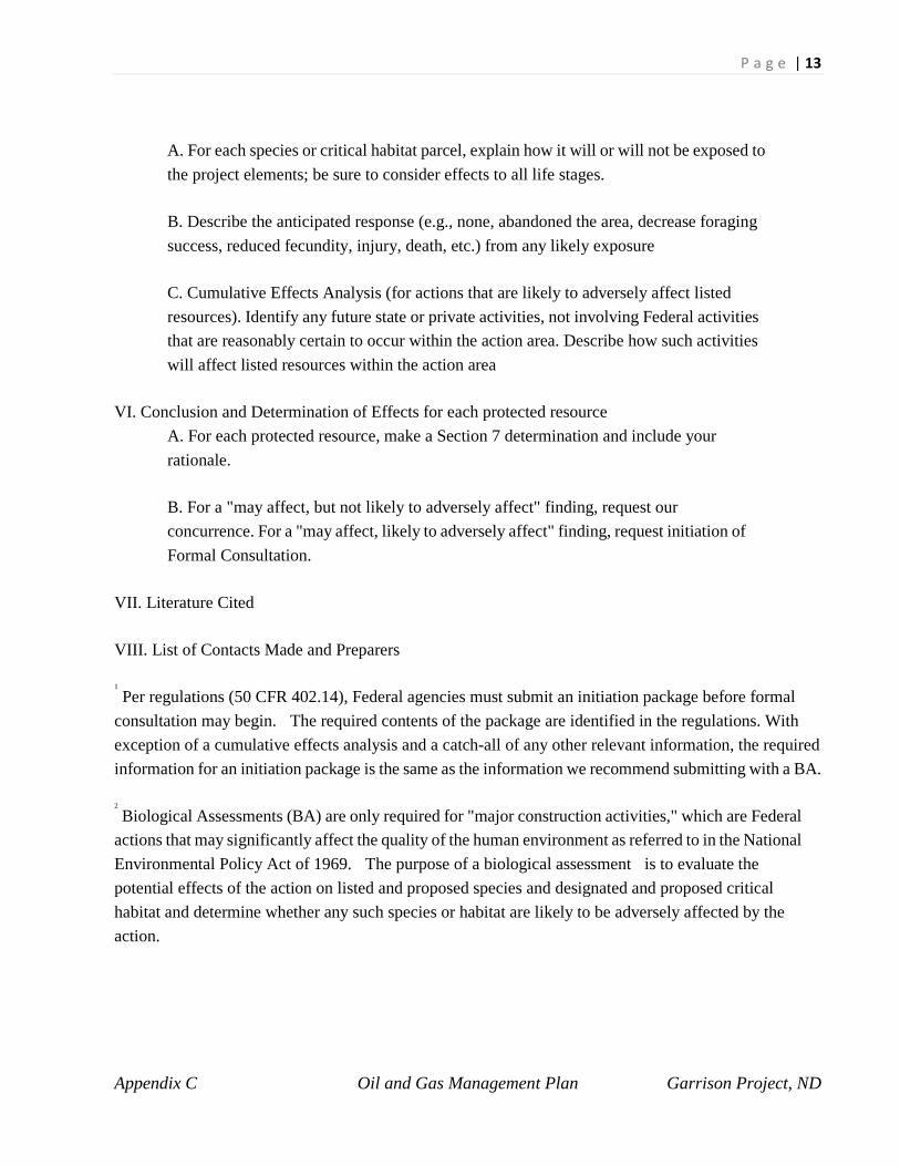
P a g e | 13
Appendix C Oil and Gas Management Plan Garrison Project, ND
A. For each species or critical habitat parcel, explain how it will or will not be exposed to the project elements; be sure to consider effects to all life stages.
B. Describe the anticipated response (e.g., none, abandoned the area, decrease foraging success, reduced fecundity, injury, death, etc.) from any likely exposure
C. Cumulative Effects Analysis (for actions that are likely to adversely affect listed resources). Identify any future state or private activities, not involving Federal activities that are reasonably certain to occur within the action area. Describe how such activities will affect listed resources within the action area
VI. Conclusion and Determination of Effects for each protected resource A. For each protected resource, make a Section 7 determination and include your rationale.
B. For a "may affect, but not likely to adversely affect" finding, request our concurrence. For a "may affect, likely to adversely affect" finding, request initiation of Formal Consultation.
VII. Literature Cited
VIII. List of Contacts Made and Preparers
1
Per regulations (50 CFR 402.14), Federal agencies must submit an initiation package before formal consultation may begin. The required contents of the package are identified in the regulations. With exception of a cumulative effects analysis and a catch-all of any other relevant information, the required information for an initiation package is the same as the information we recommend submitting with a BA.
2
Biological Assessments (BA) are only required for "major construction activities," which are Federal actions that may significantly affect the quality of the human environment as referred to in the National Environmental Policy Act of 1969. The purpose of a biological assessment is to evaluate the potential effects of the action on listed and proposed species and designated and proposed critical habitat and determine whether any such species or habitat are likely to be adversely affected by the action.

P a g e | 14
Appendix C Oil and Gas Management Plan Garrison Project, ND
3
Agencies are required to review all their actions—not just those that qualify as a “major construction activity.” This review entails assessing and documenting the effects of their action on protected resources. Whether an action qualifies as a “major construction activity” has no influence on how an agency should analyze its action or document its section 7 review. Hence, the purpose and contents of a Biological Assessment and a Biological Evaluation should be the same.
4
Formal Consultation is required if an action is likely to “adversely affect” listed species and designated critical habitat. For proposed species, further consultation is required only if the action is likely to “jeopardize the continued existence” of the species or result in “destruction or adverse modification” of critical habitat. To appropriately apply these determinations, you need to fully understand the terms “jeopardy” and “adverse modification” and must have complete knowledge of the range wide status of the species and condition of the habitat, respectively. For these reasons, agencies typically conclude “may affect, and likely to adversely affect” and contact the Service for further guidance in making the jeopardy and adverse modification determinations for proposed species critical habitat.

APPENDIX D
Best Management Practices as Conditions of Approval for Oil and Gas Development
Garrison Project, North Dakota

This space left blank intentionally.
TABLE OF CONTENTS
CLEARANCE................................................................................................................................. 1
01. NO SURFACE OCCUPANCY AND USE LIMITATIONS .............................................. 1
02. NEW DISTURBANCES ...................................................................................................... 1
MONITORING AND ASSESSMENT........................................................................................... 1
03. MONITORING AND INSPECTIONS ................................................................................ 1
04. ASSESSMENT OF STAGING AREA ................................................................................ 2
GENERAL OPERATIONS ............................................................................................................ 2
05. OPERATIONS ..................................................................................................................... 2
06. AREA OF OPERATIONS ................................................................................................... 3
CONSTRUCTION OF FACILITIES ............................................................................................. 4
07. CONSTRUCTION RESTRICTIONS .................................................................................. 4
08. SITE CONDITIONS ............................................................................................................ 5
09. CENTRALIZE FACILITIES ............................................................................................... 5
10. CLOSED LOOP SYSTEMS ................................................................................................ 5
11. CONTAINMENT SYSTEMS .............................................................................................. 6
12. DIKES .................................................................................................................................. 6
13. FENCES, GATES, & CATTLE GUARDS ......................................................................... 6
14. SIGNS .................................................................................................................................. 7
15. LIGHTS ................................................................................................................................ 7
16. PAINT .................................................................................................................................. 7
17. RIG RELEASE AND STACKING ...................................................................................... 8
WASTE MANAGEMENT ............................................................................................................. 8
18. SEWAGE CONTAINMENT PLAN ................................................................................... 8
19. WATER POLLUTION ........................................................................................................ 8
20. CONTAINMENT AND DISPOSAL ................................................................................... 9
DISTURBANCE GUIDELINES .................................................................................................... 9
21. NOISE CONTROL (MUFFLERS) ...................................................................................... 9
22. FIRE PREVENTION & SUPPRESSION AT THE WELL SITE ....................................... 9
23. FLARE PITS ........................................................................................................................ 9
24. LINES – OPEN ENDED LINES, LOAD LINES, VALVES, AND CATCH BASINS ...... 9
HAZARDOUS MATERIALS MANAGEMENT ........................................................................ 10
25. FUEL TANKS, CHEMICALS AND STORAGE ............................................................. 10
26. EMERGENCY RESPONSE PLAN .................................... Error! Bookmark not defined.
OIL AND GAS PRODUCTION .................................................................................................. 11
27. PRODUCTION FACILITIES ............................................................................................ 11
28. SPILL CONTROL & DRAINAGE ................................................................................... 11
29. WINDSOCK ...................................................................................................................... 12
TRANSPORTATION ................................................................................................................... 12
30. EQUIPMENT AND VEHICLES ....................................................................................... 12
31. HAUL ROUTE(s) AND OFF ROAD VEHICLE TRAVEL ............................................. 13
32. ROADS .............................................................................................................................. 13
VISUAL RESOURCES MANAGEMENT .................................................................................. 14
33. VISUAL RESOURCE MANAGEMENT ......................................................................... 14
WATER RESOURCES MANAGEMENT .................................................................................. 14
34. WATER SUPPLY .............................................................................................................. 14
35. AQUIFER PROTECTION ................................................................................................. 14
FISH AND WILDLIFE ................................................................................................................ 15
36. ANIMAL PROTECTION .................................................................................................. 15
37. WETLANDS, WOODY DRAWS, RIPARIAN AREAS, AND FLOODPLAINS ........... 15
38. BOTANICAL RESOURCES / HABITAT PROTECTION .............................................. 15

BEST MANAGEMENT PRACTICES AS CONDITIONS OF APPROVAL FOR OIL AND GAS DEVELOPMENT U.S. ARMY CORPS of ENGINEERS, GARRISON PROJECT For the: Operator:
Well Name:
Well Number:
County/State : Section: Township: Range:
Forward: This document provides applicants with guidelines on how to responsibly disturb surfaces at the Garrison Project, which is managed by the U.S. Army Corps of Engineers (Corps). These best management practices are conditions of approval for granting real estate easements on the Garrison Project. In addition to the items listed in this appendix, measures outlined in the site specific Environmental Assessment are also commitments made by the applicant to develop the proposed project while eliminating or reducing any potential negative impacts to the environment or the Garrison Projects authorized purposes. These commitments would become a part of the real estate easement as stipulations for surface disturbances. The easement may be revoked and operations suspended if an applicant is found to not be in compliance with the items required within this appendix and the Environmental Assessment. Not every item listed within this appendix would apply to every project. For example, pipeline development projects differ from well pad development projects. Exemptions from compliance would be determined by the Garrison Project during a project specific evaluation. The applicant should contact the Garrison Project staff early in the plan development to determine if exclusions apply.
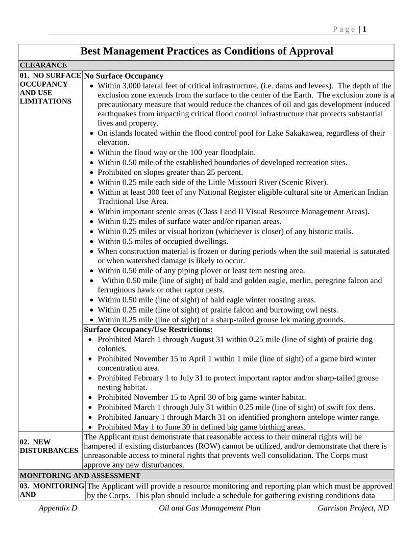
P a g e | 1
Appendix D Oil and Gas Management Plan Garrison Project, ND
Best Management Practices as Conditions of Approval
CLEARANCE 01. NO SURFACE OCCUPANCY AND USE LIMITATIONS
No Surface Occupancy • Within 3,000 lateral feet of critical infrastructure, (i.e. dams and levees). The depth of the
exclusion zone extends from the surface to the center of the Earth. The exclusion zone is a precautionary measure that would reduce the chances of oil and gas development induced earthquakes from impacting critical flood control infrastructure that protects substantial lives and property.
• On islands located within the flood control pool for Lake Sakakawea, regardless of their elevation.
• Within the flood way or the 100 year floodplain. • Within 0.50 mile of the established boundaries of developed recreation sites. • Prohibited on slopes greater than 25 percent. • Within 0.25 mile each side of the Little Missouri River (Scenic River). • Within at least 300 feet of any National Register eligible cultural site or American Indian
Traditional Use Area. • Within important scenic areas (Class I and II Visual Resource Management Areas). • Within 0.25 miles of surface water and/or riparian areas. • Within 0.25 miles or visual horizon (whichever is closer) of any historic trails. • Within 0.5 miles of occupied dwellings. • When construction material is frozen or during periods when the soil material is saturated
or when watershed damage is likely to occur. • Within 0.50 mile of any piping plover or least tern nesting area. • Within 0.50 mile (line of sight) of bald and golden eagle, merlin, peregrine falcon and
ferruginous hawk or other raptor nests. • Within 0.50 mile (line of sight) of bald eagle winter roosting areas. • Within 0.25 mile (line of sight) of prairie falcon and burrowing owl nests. • Within 0.25 mile (line of sight) of a sharp-tailed grouse lek mating grounds.
Surface Occupancy/Use Restrictions: • Prohibited March 1 through August 31 within 0.25 mile (line of sight) of prairie dog
colonies. • Prohibited November 15 to April 1 within 1 mile (line of sight) of a game bird winter
concentration area. • Prohibited February 1 to July 31 to protect important raptor and/or sharp-tailed grouse
nesting habitat. • Prohibited November 15 to April 30 of big game winter habitat. • Prohibited March 1 through July 31 within 0.25 mile (line of sight) of swift fox dens. • Prohibited January 1 through March 31 on identified pronghorn antelope winter range. • Prohibited May 1 to June 30 in defined big game birthing areas.
02. NEW DISTURBANCES
The Applicant must demonstrate that reasonable access to their mineral rights will be hampered if existing disturbances (ROW) cannot be utilized, and/or demonstrate that there is unreasonable access to mineral rights that prevents well consolidation. The Corps must approve any new disturbances.
MONITORING AND ASSESSMENT 03. MONITORING AND
The Applicant will provide a resource monitoring and reporting plan which must be approved by the Corps. This plan should include a schedule for gathering existing conditions data

P a g e | 2
Appendix D Oil and Gas Management Plan Garrison Project, ND
INSPECTIONS before, during and after construction. The plan should include baseline information on soils, vegetation, air quality, sound, visual resources, ground water, and other environmental conditions. Most of this information would be included in the Environmental Assessment. The plan should also provide details of interim reclamation measures to be implemented while the well is in production phase. A 3rd party approved by the Garrison Project but hired by the applicant will be required to monitor and submit monitoring reports to the Garrison Project during and following drilling operations. The schedule will be determined on a site specific basis in coordination with the Garrison Project staff. The Applicant shall set up a localized groundwater monitoring network which would include the installation of at least two piezometers to ensure well development does not have adverse effects on aquifers that connect to Lake Sakakawea. The Applicant is responsible for the cost to install the wells and the housing to protect the wells. The wells would be locked to avoid unauthorized entry. An independent third party approved by the Garrison Project would sample the wells for common water quality parameters to establish a baseline for the project area. During well development (i.e. hydraulic fracturing processes) and during well production, the independent third party would be responsible for taking water quality samples and submitting, as part of the monitoring report, the results to the applicant and the Garrison Project. The applicant is responsible for all payment while the sampling is being done. Standard water quality sampling methodologies should be used including the use of blind duplicates to verify integrity of sample results. Water quality sampling protocols would be provided by the U.S. Army Corps of Engineers – Omaha District. Sampling and reporting would continue for the life of the well, or until the Garrison Project determines no effect to aquifers has occurred due to well development. Operators are expected to initiate their own inspections programs, identify noncompliance, and take appropriate corrective actions and submit annual reports until the well is no longer in production and final reclamation has been completed. Final reclamation plans are not required to process an APD; however, they must be developed before well abandonment.
Remote telemetry monitoring of the production well is required. Any abnormalities which may compromise the integrity of the well must be reported to the Garrison Project Office.
04. ASSESSMENT OF STAGING AREA
Applicants are encouraged to put staging areas outside COE lands (i.e. pipeline, equipment storage, etc.). An evaluation of the proposed staging area needs to be completed. The Applicant must complete a survey to map out the boundaries of the proposed project area to depict the following information: • Existing wells (water, abandoned, temporarily abandoned, disposal, etc.) within a one-
mile radius of the location of the proposed well must be identified and submitted on a map.
• Leasehold areas (i.e. mineral leaseholds, pooled leaseholds, etc.). The Applicant must provide copies of all leases and agreements to all leasehold areas.
• tank batteries within a one mile radius of proposed staging area • Production facilities within a one mile radius of proposed staging area • Gathering and service lines (i.e. oil flow and gas gathering lines, injection lines, water
disposal lines, etc.)
GENERAL OPERATIONS 05. OPERATIONS
Staking – All areas that may be disturbed must be marked, at a minimum, with the projects and applicants name. A request should be submitted to the Garrison Project prior to staking potentially disturbed areas. Verbal approvals are acceptable. The staking must be completed

P a g e | 3
Appendix D Oil and Gas Management Plan Garrison Project, ND
prior to conducting the pre-work meeting or the meeting will be postponed and rescheduled at a later date. The following surface disturbances must be staked by the contracting company: • Well location, • Two 200 foot directional reference stakes • Exterior pad dimensions, • Cuts and fills • Outer limits of the area to be disturbed (catch points); • Any off site attendant features or temporary disturbances (i.e. stockpiling of topsoil)
Pre-work Meeting - A pre-work meeting shall be held prior to any earth disturbing activities (i.e. staking) and a starting date established. This will include, at minimum, the Applicant or their authorized representative, the dirt contractor and the authorized Corps officer. The lead Applicant is responsible for scheduling and holding this meeting in a timely manner sufficient for resolving any potential problems prior to actual disturbance. A minimum 48-hour advance notice is required. The Corps should be notified of all coordination and meeting changes in order to determine if the pre-work conference needs to be rescheduled. Surface Use Plan of Operations (SUPO) – Regardless of mineral ownership, the surface use is defined within the SUPO and is formatted per the Federal Onshore Oil and Gas Order No. 1, 12 Point Surface Use Plan of Operations. • The Onshore Oil and Gas Order No. 1 can be found at:
http://www.blm.gov/pgdata/etc/medialib/blm/wy/programs/energy/og/ogdocs.Par.47046.File.dat/onshoreorder1.pdf.
Compliance - The Applicant must conduct operations in accordance with either the approved SUPO or the approved Plan of Operations (PO). Failure to comply will result in a “Notice of Noncompliance.” The Corps will perform random inspections without notification during all phases of the operations to monitor compliance. A copy of the approved SUPO must be present on the site during drilling, siting production facilities and during any phase of reclamation. Failure to produce a copy of the SUPO would result in the immediate suspense of all operations. Pre-work Delays - The Applicant must notify the Corps 48 hours prior to commencing operations or resuming operations following any temporary cessation, delay, or down time in which 7 or more days has elapsed.
Completion and Final Inspection - The Applicant will notify the Corps when construction is completed. The Corps will then perform a final inspection to determine whether operations can proceed.
Selling or Purchasing Property - The Applicant must notify the Corps in writing no later than 30 days after a sale or transfer of facilities, a company name change, or a change in address to facilitate the modification or re-issuance of Surface Occupancy Permits (SOP) and/or Special Use (SU) permits. Failure to do so may result in shut-in, cancellation, or denied use of the Special Use facilities. This is typically done formally by a sundry “Notice of Intent.”
06. AREA OF OPERATIONS
As-built survey plats or geographical information system (GIS) shapefiles, would be submitted to the Corps upon completion of all wells, attendant facilities, roads, flow lines, pipelines, and any other attendant facilities

P a g e | 4
Appendix D Oil and Gas Management Plan Garrison Project, ND
The well site, access roads, and any other facilities associated with the well shall be maintained in an orderly and safe manner, and in accordance with the conditions herein regardless of well status.
Area of Operations Phases: • Drilling Phase - The Area of Operations during the drilling phase includes the entire
disturbed area of the well pad and ancillary facilities. • Production Phase - The Area of Operations during the production phase is the working
area of the well pad which has not been reclaimed and which includes, but is not limited to, the production facilities, all diked areas, 15 feet outside of the anchors (dependent upon anchor spacing), and any area used by vehicles regardless of frequency.
CONSTRUCTION OF FACILITIES 07. CONSTRUCTION RESTRICTIONS
Constructing Under Wet Conditions - All construction activities are subject to immediate suspension during periods of wet weather. The normal wet season in this area lasts from early March to mid June. Construction will not be allowed between the dates of March 1st – June 15th without prior approval.
Construction within Existing Right-of-Way (ROW) - When construction or maintenance of projects occurs within an existing ROW, it is the Applicant’s responsibility to obtain prior written permission from the Applicant of any easement, project work agreement, special use permit, or encroachment permit on the affected portion of the ROW. Following construction or maintenance activities, the Applicant shall return the ROW to its original condition including compacting, seeding and surfacing, if necessary. The Applicant is also responsible for any future reconstruction or maintenance needs resulting from this activity, such as compaction necessitated by pipeline settling, unless released from this liability by the Applicant of the applicable easement, project work agreement, special use permit or encroachment permit.

P a g e | 5
Appendix D Oil and Gas Management Plan Garrison Project, ND
Winter Construction – A. The winter construction period will be considered to be in effect when any of the
following conditions occur: • The ground is frozen and plating of topsoil occurs; • Equipment slippage from operating on frozen ground results in scalping into plant
root systems. • Road crossings cannot be adequately compacted. (During early freeze-up, frost
levels are normally deeper in roads than in surrounding areas.); • Topsoil is frozen and cannot be separated from sub-grade material in areas requiring
right-of-way work; • The backfill material freezes to the extent that adequate compaction becomes
difficult. • Reclamation of the entire ROW to Corps standards becomes difficult.
B. Trenching is the only acceptable method for winter construction. Plowing during frozen ground conditions results in unacceptable surface impacts. The compaction method requires prior approval prior to construction.
C. Snow is to be removed from the area of stored backfill material prior to trenching. Skids must be attached to the plow to prevent the scraping off of the topsoil. Snow is not to be mixed in with backfill material.
D. The allowable trench width depends on the compaction method. This will normally be 8, 10, or 12 inches. Narrow trench widths do not permit adequate compaction.
E. No open trench will be left at the end of each day except for the short span necessary to start from the next day.
F. Cutting of roads is limited to trenching and boring machines. Backhoes dig frozen material up in chunks and adequate compaction cannot be obtained. Backhoes are allowed at tie in points, rocky areas and when crossing other lines.
G. All construction activities are suspended during periods of winter thaw.
08. SITE CONDITIONS
During pad construction, soil conditions may need to be re-evaluated to determine if additional precautions are needed in regards to highly permeable soils. Additional erosion control measures, secondary liners and gentler slopes may need to be constructed for soil conditions that readily allow migration of fluids into the subsurface of the site or sediment via overland flow in highly erodible soils. Corps staff must be notified immediately of any changed site conditions.
09. CENTRALIZE FACILITIES
It is required that all new disturbances (e.g. roads, pipelines, electrical lines, etc.) should stay within the corridor of existing disturbances. Pipelines should run from the wellheads to centralized production facilities to help reduce truck traffic, minimize areas of spill occurrence, and reduce the footprint of the well location. Natural gas should also be piped to processing facilities if a nearby infrastructure exists.
10. CLOSED LOOP SYSTEMS
The use of a completely closed loop system including all muds, fluids, and cuttings, will be required on all wells located on Corps lands. No reserve pits will be allowed on the well location. All waste will be properly disposed of in a State approved disposal facility. Operators are not allowed to dispose of waste in commercial waste pits. The Applicant must provide documentation of all closed loop systems to the Garrison Project.
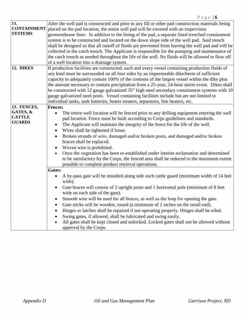
P a g e | 6
Appendix D Oil and Gas Management Plan Garrison Project, ND
11. CONTAINMENT SYSTEMS
After the well pad is constructed and prior to any fill or other pad construction materials being placed on the pad location, the entire well pad will be covered with an impervious geomembrane liner. In addition to the lining of the pad, a separate lined trenched containment system is to be constructed and located on the down slope side of the well pad. Said trench shall be designed so that all runoff of fluids are prevented from leaving the well pad and will be collected in the catch trench. The Applicant is responsible for the pumping and maintenance of the catch trench as needed throughout the life of the well. No fluids will be allowed to flow off of a well location into a drainage system.
12. DIKES
If production facilities are constructed, each and every vessel containing production fluids of any kind must be surrounded on all four sides by an impermeable dike/berm of sufficient capacity to adequately contain 100% of the contents of the largest vessel within the dike plus the amount necessary to contain precipitation from a 25-year, 24-hour storm event. Dikes shall be constructed with 12 gauge galvanized 35” high steel secondary containment systems with 10 gauge galvanized steel posts. Vessel containing facilities include but are not limited to individual tanks, tank batteries, heater treaters, separators, line heaters, etc.
13. FENCES, GATES, & CATTLE GUARDS
Fences: • The entire well location will be fenced prior to any drilling equipment entering the well
pad location. Fence must be built according to Corps guidelines and standards. • The Applicant will maintain the integrity of the fence for the life of the well. • Wires shall be tightened if loose. • Broken strands of wire, damaged and/or broken posts, and damaged and/or broken
braces shall be replaced. • Woven wire is prohibited. • Once the vegetation has been re-established under interim reclamation and determined
to be satisfactory by the Corps, the fenced area shall be reduced to the maximum extent possible to complete product retrieval operations.
Gates: • A by-pass gate will be installed along side each cattle guard (minimum width of 14 feet
wide). • Gate braces will consist of 2 upright posts and 1 horizontal pole (minimum of 8 feet
wide on each side of the gate). • Smooth wire will be used for all braces, as well as the loop for opening the gate. • Gate sticks will be wooden, round (a minimum of 2 inches on the small end). • Hinges or latches shall be repaired if not operating properly. Hinges shall be oiled. • Swing gates, if allowed, shall be lubricated and swing easily. • All gates shall be kept closed and unlocked. Locked gates shall not be allowed without
approval by the Corps.
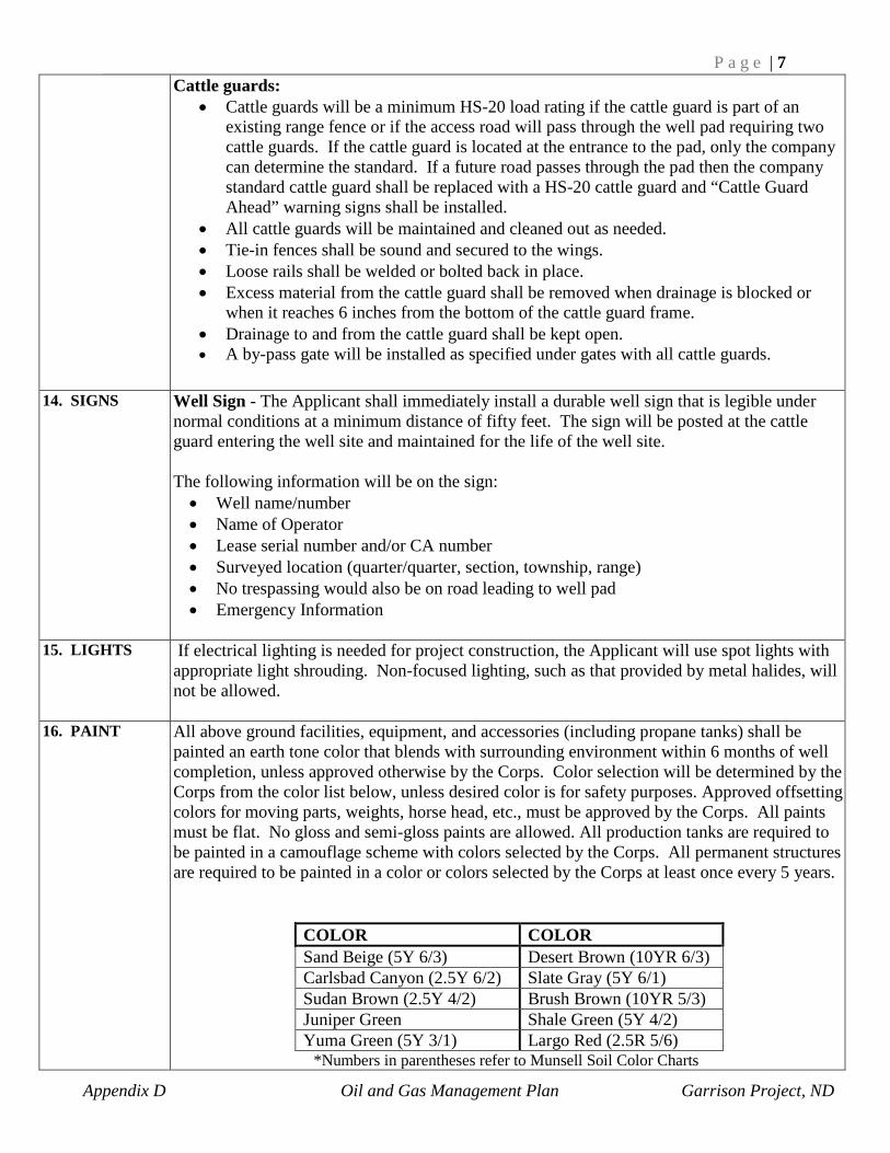
P a g e | 7
Appendix D Oil and Gas Management Plan Garrison Project, ND
Cattle guards: • Cattle guards will be a minimum HS-20 load rating if the cattle guard is part of an
existing range fence or if the access road will pass through the well pad requiring two cattle guards. If the cattle guard is located at the entrance to the pad, only the company can determine the standard. If a future road passes through the pad then the company standard cattle guard shall be replaced with a HS-20 cattle guard and “Cattle Guard Ahead” warning signs shall be installed.
• All cattle guards will be maintained and cleaned out as needed. • Tie-in fences shall be sound and secured to the wings. • Loose rails shall be welded or bolted back in place. • Excess material from the cattle guard shall be removed when drainage is blocked or
when it reaches 6 inches from the bottom of the cattle guard frame. • Drainage to and from the cattle guard shall be kept open. • A by-pass gate will be installed as specified under gates with all cattle guards.
14. SIGNS Well Sign - The Applicant shall immediately install a durable well sign that is legible under normal conditions at a minimum distance of fifty feet. The sign will be posted at the cattle guard entering the well site and maintained for the life of the well site. The following information will be on the sign: • Well name/number • Name of Operator • Lease serial number and/or CA number • Surveyed location (quarter/quarter, section, township, range) • No trespassing would also be on road leading to well pad • Emergency Information
15. LIGHTS If electrical lighting is needed for project construction, the Applicant will use spot lights with
appropriate light shrouding. Non-focused lighting, such as that provided by metal halides, will not be allowed.
16. PAINT All above ground facilities, equipment, and accessories (including propane tanks) shall be painted an earth tone color that blends with surrounding environment within 6 months of well completion, unless approved otherwise by the Corps. Color selection will be determined by the Corps from the color list below, unless desired color is for safety purposes. Approved offsetting colors for moving parts, weights, horse head, etc., must be approved by the Corps. All paints must be flat. No gloss and semi-gloss paints are allowed. All production tanks are required to be painted in a camouflage scheme with colors selected by the Corps. All permanent structures are required to be painted in a color or colors selected by the Corps at least once every 5 years.
COLOR COLOR Sand Beige (5Y 6/3) Desert Brown (10YR 6/3) Carlsbad Canyon (2.5Y 6/2) Slate Gray (5Y 6/1) Sudan Brown (2.5Y 4/2) Brush Brown (10YR 5/3) Juniper Green Shale Green (5Y 4/2) Yuma Green (5Y 3/1) Largo Red (2.5R 5/6)
*Numbers in parentheses refer to Munsell Soil Color Charts
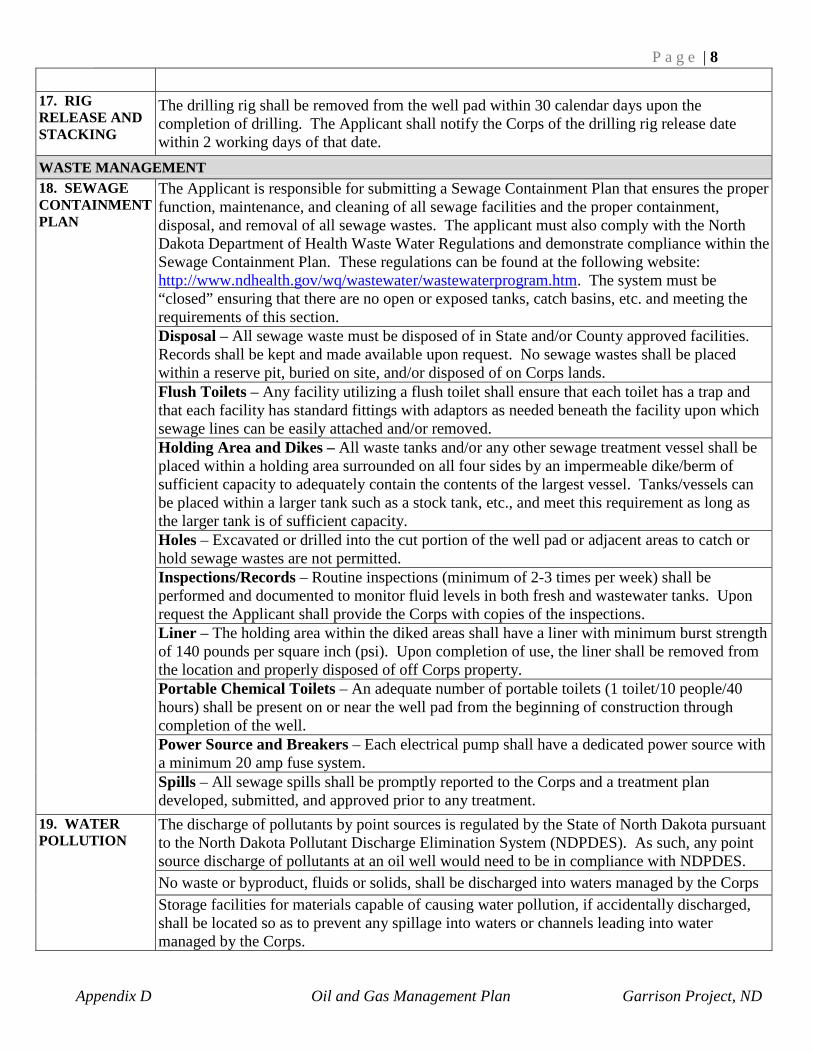
P a g e | 8
Appendix D Oil and Gas Management Plan Garrison Project, ND
17. RIG RELEASE AND STACKING
The drilling rig shall be removed from the well pad within 30 calendar days upon the completion of drilling. The Applicant shall notify the Corps of the drilling rig release date within 2 working days of that date.
WASTE MANAGEMENT 18. SEWAGE CONTAINMENT PLAN
The Applicant is responsible for submitting a Sewage Containment Plan that ensures the proper function, maintenance, and cleaning of all sewage facilities and the proper containment, disposal, and removal of all sewage wastes. The applicant must also comply with the North Dakota Department of Health Waste Water Regulations and demonstrate compliance within the Sewage Containment Plan. These regulations can be found at the following website: http://www.ndhealth.gov/wq/wastewater/wastewaterprogram.htm. The system must be “closed” ensuring that there are no open or exposed tanks, catch basins, etc. and meeting the requirements of this section. Disposal – All sewage waste must be disposed of in State and/or County approved facilities. Records shall be kept and made available upon request. No sewage wastes shall be placed within a reserve pit, buried on site, and/or disposed of on Corps lands. Flush Toilets – Any facility utilizing a flush toilet shall ensure that each toilet has a trap and that each facility has standard fittings with adaptors as needed beneath the facility upon which sewage lines can be easily attached and/or removed. Holding Area and Dikes – All waste tanks and/or any other sewage treatment vessel shall be placed within a holding area surrounded on all four sides by an impermeable dike/berm of sufficient capacity to adequately contain the contents of the largest vessel. Tanks/vessels can be placed within a larger tank such as a stock tank, etc., and meet this requirement as long as the larger tank is of sufficient capacity. Holes – Excavated or drilled into the cut portion of the well pad or adjacent areas to catch or hold sewage wastes are not permitted. Inspections/Records – Routine inspections (minimum of 2-3 times per week) shall be performed and documented to monitor fluid levels in both fresh and wastewater tanks. Upon request the Applicant shall provide the Corps with copies of the inspections. Liner – The holding area within the diked areas shall have a liner with minimum burst strength of 140 pounds per square inch (psi). Upon completion of use, the liner shall be removed from the location and properly disposed of off Corps property. Portable Chemical Toilets – An adequate number of portable toilets (1 toilet/10 people/40 hours) shall be present on or near the well pad from the beginning of construction through completion of the well. Power Source and Breakers – Each electrical pump shall have a dedicated power source with a minimum 20 amp fuse system. Spills – All sewage spills shall be promptly reported to the Corps and a treatment plan developed, submitted, and approved prior to any treatment.
19. WATER POLLUTION
The discharge of pollutants by point sources is regulated by the State of North Dakota pursuant to the North Dakota Pollutant Discharge Elimination System (NDPDES). As such, any point source discharge of pollutants at an oil well would need to be in compliance with NDPDES. No waste or byproduct, fluids or solids, shall be discharged into waters managed by the Corps Storage facilities for materials capable of causing water pollution, if accidentally discharged, shall be located so as to prevent any spillage into waters or channels leading into water managed by the Corps.

P a g e | 9
Appendix D Oil and Gas Management Plan Garrison Project, ND
20. CONTAINMENT AND DISPOSAL
All waste shall be properly disposed of in a State approved disposal facility. Waste and/or produced water is required to be disposed of at State approved reinjection sites. The applicant will be required to provide the Corps records of disposal at approved sites. The Applicant is required to bury metal and/ or plastic containment barrels at ground level to catch rig runoff and then pump remaining contents into a tank that is to be disposed of at a State approved facility. Steel containment walls are required to be placed around production facilities with waterproofed seams and lug nut holes. The walls should have the capacity to hold 1.5 times the total capacity of one tank. Berms constructed of earthen-material will not be allowed. All cuttings, water production or any other waste materials shall be disposed of in a State approved commercial disposal well or pit off project lands.
DISTURBANCE GUIDELINES 21. NOISE CONTROL (MUFFLERS)
The use of internal combustion engines to provide the prime moving power of production equipment is prohibited. All production equipment, compressors or other components associated with production facilities will be electrically powered, to avoid disturbance to the general public, wildlife, livestock and surface owners.
22. FIRE PREVENTION & SUPPRESSION AT THE WELL SITE
The Applicant shall build or construct fire lines or do such clearing around the well location for fire prevention along with having the proper personal protective equipment (PPE) on site. A 30 foot minimum bare ground buffer zone shall be maintained around any production facilities, equipment and/or accessories) limiting the likelihood of producing a flame. Examples include but are not limited to heater-treaters, flare pits, separators, line heaters, etc.
23. FLARE PITS If flaring is required, a pit must be used to minimize visual disturbance to the landscape. The flare pit must be surrounded on all four sides by an impermeable dike/berm of sufficient capacity to adequately contain any incidental discharge from flare stacks. No elevated flare stacks would be allowed. Flare pit igniters must be functional. A minimum 30 foot vegetation free buffer must be maintained around flare pit. Flare pits will not be constructed in coal seams.
24. LINES – OPEN ENDED LINES, LOAD LINES, VALVES, AND CATCH BASINS
Any open-ended line or valve on any production facilities, equipment, and/ or accessory will have catch basins installed at the point of hook-up or where the line is open or beneath the valve to capture drips and spills. They shall be of an adequate capacity and securely fastened or buried to prevent being moved in the wind and shall be kept screened and promptly emptied when full. All surface lines shall be painted. Load (truck) lines must terminate within the diked area unless approved in writing by the Corps. Tank battery vent lines must terminate within the diked area and be designed so that no liquids can flow out of the vent lines or outside of the dikes. Battery vents should not come down to ground level unless a vapor recovery system is installed to prevent the build-up of flammable vapors. Secondary gas containment lines from the production tanks to the flare pit are used to capture gas from the tanks and to contain minor spills. If approved, this line, whether buried or on surface, must be constructed so that all liquids flow into the pit.

P a g e | 10
Appendix D Oil and Gas Management Plan Garrison Project, ND
HAZARDOUS MATERIALS MANAGEMENT 25. FUEL TANKS, CHEMICALS AND STORAGE
The Applicant must disclose and provide the Corps with an inventory of the kinds, amounts, and hazards of all chemicals, additives, hydraulic fracturing fluid/mud materials, and/or any other substances used during drilling and/or production of the well. For example, the Applicant is required to provide on and off- site signs warning the dangers of hydrogen sulfide (H2S) around developed oil production sites that have the potential to produce H2S. All oil/petroleum and hazardous materials/substances must be stored on secondary containment. All flammable materials must be stored according to 29 CFR 1910. During drilling of the wells, the diesel used for the air chuggers, air compressors, etc. must be stored at the well site in fuel tanks that are double walled and sitting on a nonporous geomembrane liner. Any soils that are contaminated from incidental spills will be excavated and hauled to a State approved facility. If methanol tanks are required to prevent freeze up of air systems or other machinery it must be located within the treater building. Coordination with the Corps is required if methanol tanks are proposed for use. The Applicant is required to have copies of Safety Data Sheets (SDS) for every chemical or substance present on well pad. All containers used for chemical storage during the course of construction, drilling, completion, and production will be properly labeled with the chemical name and both physical and health hazards. Labels are required on all containers of hazardous material in the work area including materials being transferred between working areas. The maximum number of chemical containers on location shall not exceed amount needed for immediate operational use. Excess containers shall be neatly stored and empty containers shall be promptly removed. Chemical containers laid or turned on their side shall be supported off the ground in a sturdy cradle or stand equipped with a drip pan or catch basin. All storage tanks 55 gallons or larger will have routine maintenance and inspections conducted to ensure the integrity of the tanks according to STI standards and 40 CFR 112. The Applicant can reference and use the Occupational Safety and Health Act (OSHA) for health and safety requirements in the workplace at: http://www.osha.gov/pls/oshaweb/owastand.display_standard_group?p_toc_level=1&p_part_number=1910
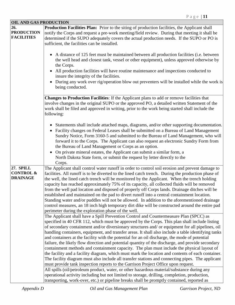
P a g e | 11
Appendix D Oil and Gas Management Plan Garrison Project, ND
OIL AND GAS PRODUCTION 26. PRODUCTION FACILITIES
Production Facilities Plan: Prior to the siting of production facilities, the Applicant shall notify the Corps and request a pre-work meeting/field review. During that meeting it shall be determined if the SUPO adequately covers the actual production needs. If the SUPO or PO is sufficient, the facilities can be installed.
• A distance of 125 feet must be maintained between all production facilities (i.e. between the well head and closest tank, vessel or other equipment), unless approved otherwise by the Corps.
• All production facilities will have routine maintenance and inspections conducted to insure the integrity of the facilities.
• During any work over rig/operation blow out preventers will be installed while the work is being conducted.
Changes to Production Facilities: If the Applicant plans to add or remove facilities that involve changes in the original SUPO or the approved PO, a detailed written Statement of the work shall be filed and approved in writing, prior to the work being started shall include the following:
• Statements shall include attached maps, diagrams, and/or other supporting documentation. • Facility changes on Federal Leases shall be submitted on a Bureau of Land Management
Sundry Notice, Form 3160-5 and submitted to the Bureau of Land Management, who will forward it to the Corps. The Applicant can also request an electronic Sundry Form from the Bureau of Land Management or Corps as an option.
• On private mineral estates, the Applicant can submit a similar form, a North Dakota State form, or submit the request by letter directly to the Corps.
27. SPILL CONTROL & DRAINAGE
The Applicant shall control water runoff in order to control soil erosion and prevent damage to facilities. All runoff is to be diverted to the lined catch trench. During the production phase of the well, the lined catch trench will be monitored by the Applicant. When the trench holding capacity has reached approximately 75% of its capacity, all collected fluids will be removed from the well pad location and disposed of properly off Corps lands. Drainage ditches will be established and maintained on the pad to divert runoff into a central containment location. Standing water and/or puddles will not be allowed. In addition to the aforementioned drainage control measures, an 18 inch high temporary dirt dike will be constructed around the entire pad perimeter during the exploration phase of the well. The Applicant shall have a Spill Prevention Control and Countermeasure Plan (SPCC) as specified in 40 CFR 112, which must be approved by the Corps. This plan shall include listing of secondary containment and/or diversionary structures and/ or equipment for all pipelines, oil handling containers, equipment, and transfer areas. It shall also include a table identifying tanks and containers at the facility with the potential for an oil discharge, the mode of potential failure, the likely flow direction and potential quantity of the discharge, and provide secondary containment methods and containment capacity. The plan must include the physical layout of the facility and a facility diagram, which must mark the location and contents of each container. The facility diagram must also include all transfer stations and connecting pipes. The applicant must provide tank inspection reports to the Garrison Project Office upon request. All spills (oil/petroleum product, water, or other hazardous material/substance during any operational activity including but not limited to storage, drilling, completion, production, transporting, work-over, etc.) or pipeline breaks shall be promptly contained, reported as

P a g e | 12
Appendix D Oil and Gas Management Plan Garrison Project, ND
specified below, and a treatment plan submitted to the Corps. The treatment plan/cleanup operations will be reviewed and approved by the Corps prior to clean up with the Corps recommendations for action followed. Soils contaminated and/or saturated as a result of a spill will not be buried or reburied as a means of treatment or disposal. Areas that have been subject to previous spills and/or saturation may have to be tested for hydrocarbons and salt concentrations prior to final reclamation, the Applicant shall employ the services of a Corps approved independent testing lab to collect and conduct the testing. It is the Applicant's responsibility to know and comply with the most current Corps spill reporting and containment requirements. The Applicant is responsible, during all activities including drilling and production periods, for all runoff or cross boundary discharge from their well site or access route, including adjacent properties whether trust, fee, State or Federal surface. This includes not only water, but any fluids or mobile elements that could be construed as a contaminant. Adequate clinker/scoria or gravel will be used on the area of operations to prevent muddy or soft ground conditions causing vehicles to rut or sink. Pad drainage devices such as valves, pipes, etc. will not be allowed. All spills must be reported to the National Response Center (NRC) and the North Dakota Department of Health.
28. WINDSOCK A functional Wind Direction Indicator (windsock or compatible) is required on all locations and must be placed on the tank battery so it is visible from everywhere on the location.
TRANSPORTATION 29. EQUIPMENT AND VEHICLES
Only equipment necessary to complete work at the pad location should be on site. The Applicant will notify the Corps of timeframes for how long equipment will be on site. Storage of unnecessary equipment will be prohibited. On the day the well goes into production, the process of removing all unnecessary equipment & trash should begin.
• Condition and Maintenance - All equipment and associated accessories shall be functional and properly maintained to prevent resource damage or shall be promptly removed from the location.
• Placement of Equipment – The resting/storage of required equipment or storage of temporary equipment (i.e. fracking containers), must be located within the boundaries of the well pad.
• Unapproved Equipment - Equipment not approved in the SUPO or PO or within an approved Sundry Notice, are to be determined as excessive equipment and shall be promptly removed from the location.
• Equipment Fluids - Motor oil, hydraulic fluids, brake fluids, antifreeze, etc. will be stored in a central location. Any used fluids must be properly disposed of off Corps lands. Soils contaminated by these fluids shall be removed and disposed of at a State approved disposal site.
• Fueling - Fueling of vehicles or storage of fuel on Corps owned lands is prohibited. If an off-site fueling location is proven to be unfeasible the Corps may reconsider. If fueling is approved on Corps land, a staging, fueling, and minor repair area for the project would be designated. All tanks would be required to be double walled and have a containment berm that would hold capacity to adequately contain 100% of the contents of the largest vessel within the dike plus the amount necessary to contain precipitation from a 25-year, 24-hour storm event. This area would be as small as possible and would require a liner and soil covering.
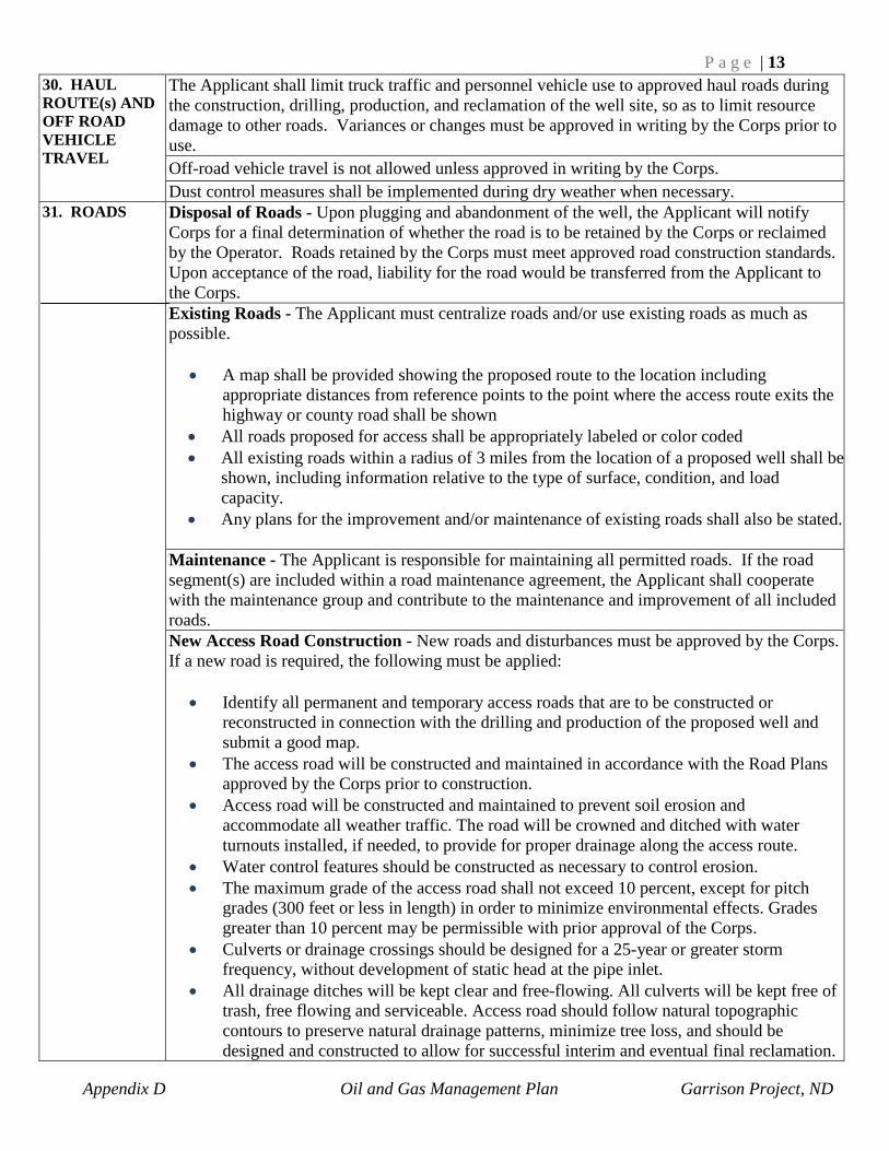
P a g e | 13
Appendix D Oil and Gas Management Plan Garrison Project, ND
30. HAUL ROUTE(s) AND OFF ROAD VEHICLE TRAVEL
The Applicant shall limit truck traffic and personnel vehicle use to approved haul roads during the construction, drilling, production, and reclamation of the well site, so as to limit resource damage to other roads. Variances or changes must be approved in writing by the Corps prior to use. Off-road vehicle travel is not allowed unless approved in writing by the Corps. Dust control measures shall be implemented during dry weather when necessary.
31. ROADS
Disposal of Roads - Upon plugging and abandonment of the well, the Applicant will notify Corps for a final determination of whether the road is to be retained by the Corps or reclaimed by the Operator. Roads retained by the Corps must meet approved road construction standards. Upon acceptance of the road, liability for the road would be transferred from the Applicant to the Corps. Existing Roads - The Applicant must centralize roads and/or use existing roads as much as possible.
• A map shall be provided showing the proposed route to the location including appropriate distances from reference points to the point where the access route exits the highway or county road shall be shown
• All roads proposed for access shall be appropriately labeled or color coded • All existing roads within a radius of 3 miles from the location of a proposed well shall be
shown, including information relative to the type of surface, condition, and load capacity.
• Any plans for the improvement and/or maintenance of existing roads shall also be stated. Maintenance - The Applicant is responsible for maintaining all permitted roads. If the road segment(s) are included within a road maintenance agreement, the Applicant shall cooperate with the maintenance group and contribute to the maintenance and improvement of all included roads. New Access Road Construction - New roads and disturbances must be approved by the Corps. If a new road is required, the following must be applied:
• Identify all permanent and temporary access roads that are to be constructed or reconstructed in connection with the drilling and production of the proposed well and submit a good map.
• The access road will be constructed and maintained in accordance with the Road Plans approved by the Corps prior to construction.
• Access road will be constructed and maintained to prevent soil erosion and accommodate all weather traffic. The road will be crowned and ditched with water turnouts installed, if needed, to provide for proper drainage along the access route.
• Water control features should be constructed as necessary to control erosion. • The maximum grade of the access road shall not exceed 10 percent, except for pitch
grades (300 feet or less in length) in order to minimize environmental effects. Grades greater than 10 percent may be permissible with prior approval of the Corps.
• Culverts or drainage crossings should be designed for a 25-year or greater storm frequency, without development of static head at the pipe inlet.
• All drainage ditches will be kept clear and free-flowing. All culverts will be kept free of trash, free flowing and serviceable. Access road should follow natural topographic contours to preserve natural drainage patterns, minimize tree loss, and should be designed and constructed to allow for successful interim and eventual final reclamation.

P a g e | 14
Appendix D Oil and Gas Management Plan Garrison Project, ND
• The topsoil will be stripped from the access road prior to any further construction activity to provide access to the subsoil, which is better suited for shaping and compaction. The amount of topsoil to be stripped will be determined by the Corps during the Environmental on-site. The stripped topsoil will be temporarily stored along the sides of the new access road and subsequently spread on the back slopes in preparation for seeding during interim reclamation.
• Implement dust suppression by spraying roads with water. • The Applicant will provide the dirt contractor with a copy of the latest revision of FP-03
Standard Specifications and Supplements for Construction of Roads and Bridges on Federal Highway Projects along with a complete set of approved road plans. Construction operations shall be suspended if the dirt contractor fails to have these documents on site.
• The Applicant will contact the Corps’ engineering representative when the construction activity is completed and prior to road surfacing for a subgrade inspection and acceptance. Subgrade acceptance is required prior to surfacing and moving equipment onto the location.
Public Access – Road will be public up to the well location. Surfacing – All access roads and production facilities are to have gravel or scoria overlay applied. Winter or Freeze-up Conditions - In the event that construction activities will occur during frozen ground and/or winter conditions, the Corps may modify the construction requirements to provide access and minimize environmental damage. In those cases, the road will be completed to final standards within the next six months. Snow and/or ice will not be incorporated into embankment or be placed to cause damage.
VISUAL RESOURCES MANAGEMENT 32. VISUAL RESOURCE MANAGEMENT
Lake Sakakawea will be managed and maintained at a Bureau of Land Management (BLM) Visual Resource Management (VRM) II rating. The objective of a VRM II classification is to retain the existing character of the landscape, with the level of change being low to the characteristics of the landscape. Projects that may degrade Lake Sakakawea to a lower classification will not be allowed. A more detailed description of VRM requirements can be found by accessing the BLM Visual Resource Management website.
• The BLM Visual Resource Management website can be found at: http://www.blm.gov/nstc/VRM
Surface occupancy and use is subject to operational constraints to maintain the landscape character intact. Deviations may be present but must repeat the form, line, color, texture, and pattern common to the landscape character so completely and to such scale that they are not evident.
WATER RESOURCES MANAGEMENT 33. WATER SUPPLY
The borrowing or taking of water from Federal lands for use during any phase of construction, drilling, operations, or maintenance is not allowed unless the Applicant has obtained all required permits and licenses. No groundwater wells for water supply will be allowed on Corps lands.
34. AQUIFER PROTECTION
The Applicant must comply with all State and Federal guidelines regarding the protection of all aquifers from contamination through communication in the borehole. See BMP #3 for information regarding groundwater monitoring requirements.
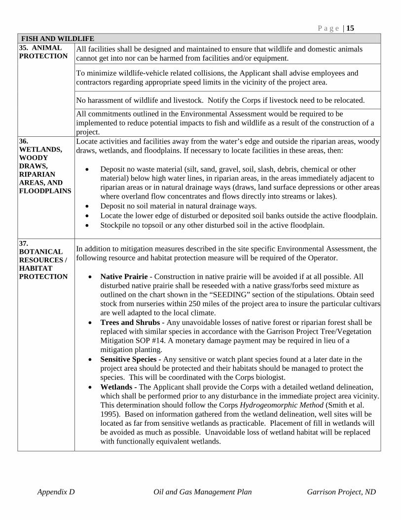
P a g e | 15
Appendix D Oil and Gas Management Plan Garrison Project, ND
FISH AND WILDLIFE 35. ANIMAL PROTECTION
All facilities shall be designed and maintained to ensure that wildlife and domestic animals cannot get into nor can be harmed from facilities and/or equipment.
To minimize wildlife-vehicle related collisions, the Applicant shall advise employees and contractors regarding appropriate speed limits in the vicinity of the project area.
No harassment of wildlife and livestock. Notify the Corps if livestock need to be relocated.
All commitments outlined in the Environmental Assessment would be required to be implemented to reduce potential impacts to fish and wildlife as a result of the construction of a project.
36. WETLANDS, WOODY DRAWS, RIPARIAN AREAS, AND FLOODPLAINS
Locate activities and facilities away from the water’s edge and outside the riparian areas, woody draws, wetlands, and floodplains. If necessary to locate facilities in these areas, then:
• Deposit no waste material (silt, sand, gravel, soil, slash, debris, chemical or other
material) below high water lines, in riparian areas, in the areas immediately adjacent to riparian areas or in natural drainage ways (draws, land surface depressions or other areas where overland flow concentrates and flows directly into streams or lakes).
• Deposit no soil material in natural drainage ways. • Locate the lower edge of disturbed or deposited soil banks outside the active floodplain. • Stockpile no topsoil or any other disturbed soil in the active floodplain.
37. BOTANICAL RESOURCES / HABITAT PROTECTION
In addition to mitigation measures described in the site specific Environmental Assessment, the following resource and habitat protection measure will be required of the Operator.
• Native Prairie - Construction in native prairie will be avoided if at all possible. All
disturbed native prairie shall be reseeded with a native grass/forbs seed mixture as outlined on the chart shown in the “SEEDING” section of the stipulations. Obtain seed stock from nurseries within 250 miles of the project area to insure the particular cultivars are well adapted to the local climate.
• Trees and Shrubs - Any unavoidable losses of native forest or riparian forest shall be replaced with similar species in accordance with the Garrison Project Tree/Vegetation Mitigation SOP #14. A monetary damage payment may be required in lieu of a mitigation planting.
• Sensitive Species - Any sensitive or watch plant species found at a later date in the project area should be protected and their habitats should be managed to protect the species. This will be coordinated with the Corps biologist.
• Wetlands - The Applicant shall provide the Corps with a detailed wetland delineation, which shall be performed prior to any disturbance in the immediate project area vicinity. This determination should follow the Corps Hydrogeomorphic Method (Smith et al. 1995). Based on information gathered from the wetland delineation, well sites will be located as far from sensitive wetlands as practicable. Placement of fill in wetlands will be avoided as much as possible. Unavoidable loss of wetland habitat will be replaced with functionally equivalent wetlands.
APPENDIX E
Army Regulation 405-30 Mineral Exploration and Extraction
On Army Controlled Lands

This space left blank intentionally.

Army Regulation 405–30
Real Estate
MineralExplorationand Extraction
HeadquartersDepartment of the ArmyWashington, DC15 July 84
Unclassified

SUMMARY of CHANGEAR 405–30Mineral Exploration and Extraction

HeadquartersDepartment of the ArmyWashington, DC15 July 84
Real Estate
Mineral Exploration and Extraction
Army Regulation 405–30
Effective 15 August 84
History. Not applicable.Summary. This regulation implements De-partment of Defense; Directive 4700.3. on
m i n e r a l e x p l o r a t i o n a n d e x t r a c t i o n o n A r -my–controlled lands.Applicability. This regulation applies to theActive Army, US Army Reserve, Army Na-t i o n a l G u a r d , a n d e l e m e n t s d e a l i n g w i t hArmy civil works.P r o p o n e n t a n d e x c e p t i o n a u t h o r i t y .Not applicable.
Impact on New Manning System. Thisregulation does not contain information thataffects the New Manning System.A r m y m a n a g e m e n t c o n t r o l p r o c e s s .Not applicable.Supplementation. Supplementation of thisr e g u l a t i o n i s p r o h i b i t e d w i t h o u t p r i o r a p -proval from HQDA(DAEN–REM), Wash DC20314.Interim changes. Interim changes to this
regulation are not official unless they are au-thenticated by the Adjutant General. Userswill destroy interim changes on their expira-tion dates unless sooner superseded or re-scinded.
S u g g e s t e d I m p r o v e m e n t s . T h e p r o p o -nent agency of this regulation is the Officethe Chief of Engineers. Users are invited tosend comments and suggested improvementson DA Form 2028 (Recommended Changesto Publications and Blank Forms) directly toHQDA(DAEN–REM), Wash DC 20314.
Distribution.T o b e d i s t r i b u t e d i n a c c o r d a n c e w i t h D AForm 12–9A requirements for AR, Real Es-tate. Active Army, C; ARNG, D; USAR, D.
Contents (Listed by paragraph and page number)Purpose • 1, page 1References • 2, page 1Explanation of abbreviations and terms • 3, page 1Responsibilities • 4, page 1Type and location of mineral • 5, page 1Availability of minerals • 6, page 1Oil and gas leasing • 7, page 1Oil and gas lease operations • 8, page 2Other mineral leases • 9, page 3Permission to explore for minerals • 10, page 3
Appendixes
A. Stipulations, page 4
B. Adequate Surface Use Program, page 4
Glossary
AR 405–30 • 15 July 84 i
Unclassified

RESERVED
ii AR 405–30 • 15 July 84
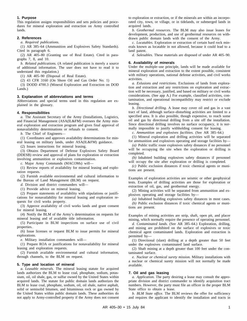
1. PurposeThis regulation assigns responsibilities and sets policies and proce-dures for mineral exploration and extraction on Army controlledlands.
2. Referencesa. Required publications.(1) AR 385–64 (Ammunition and Explosives Safety Standards).
Cited in paragraph 6.(2) AR 405–80 (Granting use of Real Estate). Cited in para-
graphs 7, 8, and 10.b. Related publications. (A related publication is merely a source
of additional information. The user does not have to read it tounderstand this regulation.)
(1) AR 405–90 (Disposal of Real Estate).(2) 43 CFR 3160 (On Shore Oil and Gas Order No. 1)(3) DODD 4700.3 (Mineral Exploration and Extraction on DOD
Lands.)
3. Explanation of abbreviations and termsAbbreviations and special terms used in this regulation are ex-plained in the glossary.
4. Responsibilitiesa. The Assistant Secretary of the Army (Installations, Logistics,
and Financial Management (ASA(IL&FM) oversees the Army min-eral exploration and extraction program and gives final approval ofnonavailability determinations or refusals to consent.
b. The Chief of Engineers—(1) Coordinates and approves availability determinations for min-
eral leasing on military lands, under ASA(IL&FM) guidance.(2) Issues instructions for mineral leasing.( 3 ) O b t a i n s D e p a r t m e n t o f D e f e n s e E x p l o s i v e s S a f e t y B o a r d
(DDESB) review and approval of plans for exploration or extractioninvolving ammunition or explosives contamination.
c. Major Army Commands (MACOMs) will—(1) Review reports of availability for mineral leasing and explo-
ration requests.(2) Furnish available environmental and cultural information to
the Bureau of Land Management (BLM) on request.d. Division and district commanders will—(1) Provide advice on mineral leasing.(2) Prepare statements of availability with stipulations or justifi-
cations for nonavailability for mineral leasing and exploration re-quests for civil works property.
(3) Approve availability of civil works lands and grant consentfor mineral leasing.
(4) Notify the BLM of the Army’s determination on requests formineral leasing and of available title information.
( 5 ) P a r t i c i p a t e i n B L M i n s p e c t i o n s o n s u r f a c e u s e o f c i v i lproperties.
(6) Issue licenses or request BLM to issue permits for mineralexplorations.
e. Military installation commanders will—(1) Prepare ROA or justifications for nonavailability for mineral
leasing and exploration requests.( 2 ) F u r n i s h a v a i l a b l e e n v i r o n m e n t a l a n d c u l t u r a l i n f o r m a t i o n ,
through channels, to the BLM on request.
5. Type and location of minerala. Leasable minerals. The mineral leasing statute for acquired
lands authorizes the BLM to lease coal, phosphate, sodium, potas-sium, oil, oil shale, gas, or sulfur owned by the United States withinacquired lands. The statute for public domain lands authorizes theBLM to lease coal, phosphate, sodium, oil, oil shale, native asphalt,solid or semisolid bitumen, and bituminous rock or gas owned bythe United States within public domain lands. These authorities donot apply to Army-controlled property if the Army does not consent
to exploration or extraction, or if the minerals are within an incorpo-rated city, town, or village, or in tidelands, or submerged lands inacquired lands.
b. Geothermal resources. The BLM may also issue leases fordevelopment, production, and use of geothermal resources on with-drawn public domain lands with the consent of the Army.
c. Locatables. Exploration or extraction of certain hard rock min-erals known as locatable in not allowed, because it could lead to aland patent.
d. Salesables. These materials are disposed of under AR 405–90.
6. Availability of mineralsUnder the multiple–use principle, lands will be made available formineral exploration and extraction to the extent possible, consistentwith military operations, national defense activities, and civil worksactivities.
a. Exlusions and restrictions. Exclusions of lands from explora-tion and extraction and any restrictions on exploration and extrac-tion will be necessary, justified, and based on military or civil worksconsiderations. (See app A.) For example, classified activities, con-tamination, and operational incompatibility may restrict or excludeleasing.
b. Directional drilling. A lease may cover oil and gas in a vasttract of land, although surface–disturbing activities are limited to aspecified area. It is also possible, though expensive, to reach someoil and gas by directional drilling from a site off the installation.Since directional drilling involves no surface occupancy, it is nor-mally impossible to justify withholding consent for leasing.
c. Ammunition and explosives facilities. (See AR 385–64.)(1) Mineral exploration and drilling activities will be separated
for ammunition and explosives operating and storage facilities by—(a) Public traffic route explosives safety distances if no personnel
w i l l b e o c c u p y i n g t h e s i t e w h e n t h e e x p l o r a t i o n o r d r i l l i n g i scompleted.
(b) Inhabited building explosives safety distances if personnelwill occupy the site after exploration or drilling is completed.
(c) Public exclusion distances if toxic chemical agents or muni-tions are present.
Examples of exploration activities are seismic or other geophysicaltests. Examples of drilling activities are those for exploration orextraction of oil, gas, and geothermal energy.
(2) Mining activities will be separated from ammunition and ex-plosives operating and storage facilities by—
(a) Inhabited building explosives safety distances in most cases.(b) Public exclusion distances if toxic chemical agents or muni-
tions are present.
Examples of mining activities are strip, shaft, open pit, and placermining, which normally require the presence of operating personnel.
d. Contaminated lands. (See AR 385–64.) Exploration, drilling,and mining are prohibited on the surface of explosives or toxicchemical agent contaminated lands. Exploration and extraction ispermitted by—
(1) Directional (slant) drilling at a depth greater than 50 feetunder the explosives contaminated land surface.
(2) Shaft mining at a depth greater than 100 feet under the con-taminated surface.
e. Nuclear or chemical surety mission. Military installations witha nuclear or chemical surety mission will not normally be madeavailable.
7. Oil and gas leasinga. Application. The party desiring a lease may consult the appro-
priate division and district commander to identify acquisition tractnumbers. However, the party must file an officer in the proper BLMState office to obtain a lease.
b. BLM State office. The BLM reviews the offer for sufficiencyand requires the applicant to identify the installation and tracts in
1AR 405–30 • 15 July 84

the offer. If the BLM accepts the offer, it forwards the offer and atitle information request to the affected installation.
c. Installation. The installation decides whether and under whatconditions minerals may be made available. The installation pre-pares an ROA for military properties under AR 404–80, or anexplanation for denying leasing. When completed, it is sent throughthe MACOM to HQDA(DAEN–ZCI), Wash DC 20310. The divi-sion or district commander prepares such data for civil propertiesa n d f o r w a r d s j u s t i f i c a t i o n s f o r n o n a v a i l a b i l i t y t oHQDA(DAEN–REM), Wash DC 20314. The division or districtcommander determines if civil works property is available. An ROAor civil works availability statement must indicate conditions underwhich exploration and extraction could be allowed, because theseconditions will become part of the lease. The ROA or civil worksavailability statement will identify any known significant resourcesthat may affect the lessee’s exploration and extraction plans. TheROA will also include information per paragraph 3–6B of the Ap-pendix to AR 385–64 on leasing close to ammunition and explo-sives facilities or land that is contaminated or suspected to becontaminated with explosives. Stipulations will be justified and willnot duplicate the BLM regulations or standard lease terms. (See appA.) Because of the technical nature of oil and gas leasing, theinstallation should consult the BLM or the division or district com-mander in developing the ROA.
d. Chief of Engineers. DAEN–ZCI staffs and approves the ROAo r j u s t i f i c a t i o n s f o r n o n a v a i l a b i l i t y f o r m i l i t a r y p r o p e r t i e s .DAEN–REM staffs and obtains DAEN–CWO approval for non-availability of civil properties. DAEN–REM will obtain DDESPreview and approval of plans for leasing close to ammunition andexplosives facilities, or for leasing land that is contaminated ors u s p e c t e d o r s u s p e c t e d t o b e c o n t a m i n a t e d w i t h e x p l o s i v e s .DDAEN–REM forwards any approved ROA to the division or dis-trict commander for action and recommends that ASA (IL&FM)withhold consent for other cases.
e. The Secretariat. ASA(IL&FM) will review justifications fornonavailability and decide whether to withhold consent for leasing.I f c o n s e n t i s w i t h h e l d , A S A ( I L & F M ) w i l l r e t u r n t h e a c t i o n t oHQDA(DAEN–REM) for forwarding it to the division or districtcommander.
f. Division or district commander. Division or district command-ers will—
(1) Develop available title information for acquired lands andidentify outstanding interests (e.g., easements) on withdrawn publicdomain land. The commander will indicate when Army title recordsare incomplete.
(2) Consent or inform the BLM of the decision to withholdconsent for leasing. Consents will include required stipulation andavailable title information. The commander will request an opportu-nity to review the mineral lease before execution in the case ofnoncompetitive leasing or before the offer of the mineral interest forsale in the case of competitive leasing. The commander will requirean opportunity to review new or changed stipulations in advance.The affected installation will take part in such a review.
g. Leasing. As the lead agency, the BLM will prepare necessarye n v i r o n m e n t a l a n d c u l t u r a l d o c u m e n t s b e f o r e d e c i d i n g t o l e a s e .BLM may consult the Army as cooperating agency for availableenvironmental and cultural information. Then the BLM grants thelease, with the stipulations required by the Army, and furnishes acompleted copy to the division or district commander or the installa-tion commander who sends a copy to the division or district com-m a n d e r . T h e d i v i s i o n o r d i s t r i c t c o m m a n d e r w i l l m a r k t h einstallation map to identify mineral leases on the property.
8. Oil and gas lease operationsWhere surface occupancy is allowed under a lease, a separate proce-dure, detailed in 43 CFR 3160, is followed to approve the lessee’soperations. The procedure is described generally below. Lesseesmust obtain prior approval for any surface disturbing activities.
a. Advance action by lessees. Before applying to the BLM forapproval, the lessee may contact the installation for information to
develop a surface use program, which the installation will approve.The installation will provide available information on properties in,or eligible for, the National Register for Historic Places, threatenedor endangered species, and critical habitats on the leased area.
b. Drilling operations.(1) Notice of staking (NOS). The lessee may furnish the BLM
and the installation an NOS before filing an Application for Permitto Drill (APD) to the BLM. The installation will review the NOSand determine if an additional license is needed for the lessee towork outside the leased area. If so, the installation will prepare anROA in accordance with AR 405–80.
(2) Applications for Permit to Drill (APD). The lessee must filean APD with the BLM. The BLM will consult with the installationon the surface use of the program of the drilling plan in the APD.
(3) Operations approval. The installation will take part in thepredrill inspection and promptly give the BLM any additional sur-face protection, safety, or reclamation stipulations. If plans not ap-p r o v e d b y D D E S B i n v o l v e e x p l o r a t i o n o r e x t r a c t i o n c l o s e t oammunition and explosives facilities, or on land that is contami-nated or suspected to be contaminated with explosives, the installa-tion must submit a proposal under paragraph 3–6B of the appendixto AR 385–64. Stipulations will relate directly to details of theproposed plan of operations, and each stipulation must be objec-tively justifiable, based on military or civil works considerations.The BLM will normally schedule the inspection within 15 days afterreceiving the NOS or APD. The BLM will include the added stipu-lations in the completed application before approval. At the sametime, the installation should review the surface use program of theADP for adequacy and advise the BLM of any needed changes. Anadequate program is safe, protects the surface, and describes properacceptable reclamation measures. (See app B.)
(4) Subsequent operations approval. Subsequent operations ap-proval. Except in emergencies, the BLM must consult with theinstallation that must approve, in advance, a change not alreadyapproved in the APD for surface use due to new construction,reconstruction, or alterations. The installation will attend site inspec-tions arranged by the BLM.
(5) Lease extension. The BLM must extend leases as long as oiland gas are produced in paying quantities.
(6) Well abandonment. The BLM will not approve final abandon-ment until the installation advises that it is satisfied with the recla-mation work, as required by the APD or the approved abandonmentnotice. The BLM will consult with the installation. The installationmay assume responsibility for a well with fresh water if funds areavailable to reimburse the lessee for recoverable casing and well-head equipment used only for the conversion to a water well. Thelessee is still responsible to complete surface cleanup. Otherwise,the installation will advise the BLM of any further reclamationmeasures required.
c. Cancellation. Unlike most other leases, mineral leases conveymore than a right to use and occupy property. They also convey aright to the property itself, i.e., all leased minerals in place and allthat the lessee severs or extracts, unless such right is affected by astipulation in the lease. Therefore, lease cancellation involves takingpossibly valuable property rights where minerals are known to exist.BLM has established the following procedures for canceling orotherwise ending a lease:
(1) The Secretary of the Interior may cancel a lease after givingnotice if the leased area contains valuable oil and gas deposits, andif after notice of noncompliance, the lessee or bona fide purchase ofthe lease interest continues to violate the mineral leasing statute,regulations, or provisions.
(2) The BLM may suspend a lease, i.e., temporarily discontinuethe right to explore and extract oil and gas. Usually, the BLMextends the lease term for the suspension period. The Secretary ofthe Army or designee may also suspend lease operation under alease stipulation (app A). Also, a leasee may give up a lease or anylegal subdivision of a lease. Finally, the lease automatically termi-nates for nonpayment of rent under certain conditions, but may laterbe reinstated by the BLM.
2 AR 405–30 • 15 July 84

9. Other mineral leasesAs explained in paragraph 5, the BLM may grant leases for othertypes of minerals. Leases for these minerals are less frequent andprocedures are usually more complicated. This regulation also ap-plies to such leases. However, DAEN–REM will advise MACOMson specific procedures on each case.
10. Permission to explore for mineralsIn some cases, a party may request permission to conduct geophysi-cal tests to explore for minerals before requesting a lease. Seismictesting is most common.
a. Army licenses. Usually the Army will grant permission in theform of a license. The affected installation will require a detailedoperations plan from the interested party. The installation will pre-pare an ROA or similar data for civil works property with requireds t i p u l a t i o n s a n d e n v i r o n m e n t a l a n d c u l t u r a l i n f o r m a t i o n . T h eMACOM or its designee must approve an ROA for military proper-ty. The division or district commander will issue the license underAR 405–80. Licenses will prohibit extraction and require the opera-tor to contact the installation before entry. The licensee must furnisha performance bond under BLM regulations and advise the BLM ofits findings. These findings are the licensee’s property, and they areconfidential until disclosure of the findings does not adversely affectthe competitive position of the licensee. The division or districtcommander will monitor license compliance.
b. BLM permits. In unusual circumstances, the BLM may beasked to issue a permit for exploration. Unusual circumstances in-clude requests involving complex technology requiring the expertiseof BLM, that may result in litigation, or to explore in Alaska. Theaffected military designee for approval. The division or district com-mander will ask the BLM to issue the permit. The BLM, as the leadagency, will insure compliance with the National EnvironmentalProtection Act before issuing the permit. The affected installationwill give available environmental and cultural information to theBLM or request. On completion of work, the permittee will advisethe BLM and the installation of compliance with all permit require-ments. The installation will advise the district commander and theBLM within 60 days if further restoration is required. The BLM willassist the installation and the district commander in monitoringlicense compliance.
3AR 405–30 • 15 July 84

Appendix AStipulations
A–1. StipulationsMineral leases grant the right to operate in the leased area formineral production. Stipulations are contract terms that restrict thelessee’s right to operate. The authority to deny lessee operationsmust be established by lease stipulations.
A–2. DraftingTo prevent challenges to lease, stipulations should be carefully writ-ten. They should be clear enough for the potential lessee to estimatethe value of leasing. Stipulations should specify the reason forrestricting operations and the land affected. For example, “The les-see may not operate in Tract A because it contains a critical wildlifehabitat.” Stipulations should also permit a waiver of the restriction ifpertinent conditions change or if the lessee can operate withoutcausing unacceptable effects. For example, “Operations on Tract Bwill not be approved, unless it is shown to the satisfaction of theinstallation commander that mineral operations will not interferewith training.”
A–3. Mandatory stipulationsAll leases will contain the following stipulations:
a. The Secretary of the Army or designee reserves the right torequire suspension of operations in a national emergency or if theArmy needs the lease area for a mission that is not compatible withlease operations. Use of this right will have prior MACOM concur-rence. On approval from higher authority, the installation com-mander for military property or the project manager for civil worksproperty will give the lessee written notice, or when time permits,request the BLM to give notice of the requirement to suspendoperations. Copies of this notice must be simultaneously provided tothe MACOM; HQDA(DAEN–REM), Wash DC 20314; the appro-priate district commander; the operator; and the BLM. The lesseeand the operator agree to this condition and waive the right tocompensation for its exercise. The lessee and the operator agree tothis condition and waive the right to compensation for its exercise.
b. If the installation commander (military) or project manager(civil work) finds an imminent danger to safety or security, theinstallation commander or the project manager may order an imme-diate stop of such activities. The regional director of BLM; theMACOM; HQDA(DAEN–REM), Wash DC 20314; the appropriatedistrict commander, and the lessee will be notified immediately. Onreceipt of the notice, the regional director will review the order anddetermine the need for other remedial action.
c. The operator will immediately stop work if contamination isfound in the operating area and ask the installation commander forhelp.
A–4. NecessityStipulations must be necessary.
a. Proposed stipulations that duplicate standard lease terms, pub-l i s h e d r e g u l a t i o n s , o r p u b l i s h e d o p e r a t i n g o r d e r s s h o u l d b eeliminated.
b. Stipulations that restrict economical extraction of a mineralshould be included.
A–5. JustificationStipulations must be justified.
a. Proposed stipulations that restrict operations, because they areincompatible with resources, values, uses, or users elsewhere at nocost to the United States during the period of operations.
b. Installations should be prepared at all times to explain why thestipulations are required. Installations should similarly be preparedto show that less restrictive stipulations were considered but rejectedas not promoting the national defense or not being in the publicinterest. This may be done by referring to mission statements, plansor similar materials, by separate explanation or by another reasona-ble method. Explanations should contain enough information on
surface resources, values, uses, and users to show which landsrequire the protection of a stipulation.
A–6. Information noticesAt the time of leasing, the installation may wish to give the lesseeinformation that will not restrict lessee operations. This informationmight help the lessee write an acceptable plan of operations orclarify administrative matters. In such cases, the installation shouldrecommend that the information be included in the lease as aninformation notice and not as a stipulation.
A–7. BLM assistanceInstallations are encouraged to consult the BLM or the division ordistrict commander for help in drafting leasing stipulations.
Appendix BAdequate Surface Use ProgramThe lessee will furnish information under guidelines to BLM. Theinstallation must review the information to insure that the surfaceuse program is safe, protects the surface, and describes acceptablereclamation measures.
B–1. Existing accessProvide for maintenance of existing access roads per installationstandards. (Use of any rail facilities, piers, and docks will also beaddressed.)
B–2. Other accessGive detailed information on construction or reconstruction of ac-cess roads.
B–3. WellsLocate all existing wells on a map or plat.
B–4. Proposed constructionLocate existing and proposed production facilities and lines on amap or plat, with dimensions of proposed construction.
B–5. Water supplyDescribe in writing, or depict on a map or plat, the source of thewater supply to be used in drilling and the method of transportingwater from or across Federal or Indian lands.
B–6. Construction materialsD e s c r i b e i n w r i t i n g o r d e p i c t o n a m a p o r p l a t t h e s o u r c e o ffederally owned construction materials, such as sand, gravel, stone,and soil. BLM will approve use of construction materials on ac-quired lands for use off the installation, under existing disposalinstructions.
B–7. Disposal of waste materialDescribe in writing, methods and locations for containment anddisposal of waste, and plans for disposal of drilling fluids, oil, andwater recovered during operations.
B–8. Ancillary facilitiesDescribe in writing and depict on a map or plat the location, re-quired land areas, and construction methods and standards for ancil-lary facilities.
B–9. Site layoutDescribe the well–site layout. Locate the drill pad, reserve and burnpits, access roads to the pad, turnaround areas, parking areas, livingfacilities, soil material stock piles, and the orientation of the rig on aplat. Furnish a cross-section diagram of the drill pad showing anycuts and fills. Describe plans to line the reserve pit.
B–10. ReclamationState plans for reclamation of the surface, with a time for com-mencement and completion.
4 AR 405–30 • 15 July 84

Glossary
Section IAbbreviations
APDApplication for Permit to Drill
BLMBureau of Land Management
CFRCode of Federal Regulations
DDESBD e p a r t m e n t o f D e f e n s e E x p l o s i v e S a f e t yBoard
DODDepartment of Defense
MACOMmajor Army command
NOSnotice of staking
ASA(IL&FM)A s s i s t a n t S e c r e t a r y o f t h e A r m y ( I n s t a l l a -tions, Logistics, and Financial Management)
ROAreport of availability
Section IITerms
AbandonmentAny process to reclaim or restore real estateunder a plan approved by the BLM and theA r m y , w h e r e o p e r a t i o n s ( i n c l u d i n g a d r yh o l e ) o r p r o d u c t i o n h a s o c c u r r e d a n d h a sceased.
Acquired LandsLands owned by the United States obtainedby purchase, gift, or condemnation.
Directional DrillingDrill from a point of the installation to reacho i l o r g a s u n d e r t h e i n s t a l l a t i o n . S l a n tdrilling.
Geophysical testingA search for a mineral that involves a physi-cal presence on the land, and testing maycause damage. Does not include core drillingfor geological information or extraction ofthe mineral.
InstallationA military or civil works project.
LeasablesUS-owned minerals, including oil and gas,s u b j e c t t o l e a s e u n d e r t h e m i n e r a l l e a s i n glaws.
LocatablesUS-owned minerals, including gold and sil-ver, on public domain lands subject to dis-covery and claim. These are not leasable orsaleable materials.
Public domainLands owned by the United States, adminis-tered by the Department of the Interior underpublic land laws.
SalablesU S - o w n e d m a t e r i a l s , i n c l u d i n g s a n d , c l a y ,and gravel.
Seismic testingA procedure to gather evidence on the poten-tial for oil and gas reservoirs by chartingsound waves into the earth and back to thesurface.
Withdrawn public domain landsPublic domain lands reserved for use by aUS agency for a specific purpose.
Section IIISpecial Abbreviations and TermsThis section contains no entries.
5AR 405–30 • 15 July 84

Unclassified PIN 056614–00

USAPAELECTRONIC PUBLISHING SYSTEMTEXT FORMATTER ... Version 2.45
PIN: 056614–00DATE: 07-23-98TIME: 08:53:47PAGES SET: 9
DATA FILE: t38.filDOCUMENT: AR 405–30DOC STATUS: NEW PUBLICATION

This space left blank intentionally.

APPENDIX F
Requirements and Document Examples for
Horizontal Directional Drill Applicants

This space left blank intentionally.

Table of Contents A Partial List of Requirements for Pipeline Installation Using HDD Techniques. ............ 1
Example of a Procedure for Monitoring and Management of Down Hole Pressure during HDD installation under FEATURE .................................................................................... 5
Example of a horizontal drilling frac out plan .................................................................... 8
_Toc332695695
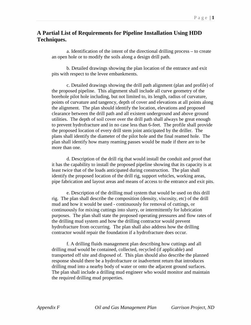
P a g e | 1
Appendix F Oil and Gas Management Plan Garrison Project, ND
A Partial List of Requirements for Pipeline Installation Using HDD Techniques.
a. Identification of the intent of the directional drilling process – to create an open hole or to modify the soils along a design drill path.
b. Detailed drawings showing the plan location of the entrance and exit pits with respect to the levee embankments.
c. Detailed drawings showing the drill path alignment (plan and profile) of
the proposed pipeline. This alignment shall include all curve geometry of the borehole pilot hole including, but not limited to, its length, radius of curvature, points of curvature and tangency, depth of cover and elevations at all points along the alignment. The plan should identify the location, elevations and proposed clearance between the drill path and all existent underground and above ground utilities. The depth of soil cover over the drill path shall always be great enough to prevent hydrofracture and in no case less than 6-feet. The profile shall provide the proposed location of every drill stem joint anticipated by the driller. The plans shall identify the diameter of the pilot hole and the final reamed hole. The plan shall identify how many reaming passes would be made if there are to be more than one.
d. Description of the drill rig that would install the conduit and proof that
it has the capability to install the proposed pipeline showing that its capacity is at least twice that of the loads anticipated during construction. The plan shall identify the proposed location of the drill rig, support vehicles, working areas, pipe fabrication and layout areas and means of access to the entrance and exit pits.
e. Description of the drilling mud system that would be used on this drill
rig. The plan shall describe the composition (density, viscosity, etc) of the drill mud and how it would be used - continuously for removal of cuttings, or continuously for mixing cuttings into slurry, or intermittently for lubrication purposes. The plan shall state the proposed operating pressures and flow rates of the drilling mud system and how the drilling contractor would prevent hydrofracture from occurring. The plan shall also address how the drilling contractor would repair the foundation if a hydrofracture does occur.
f. A drilling fluids management plan describing how cuttings and all
drilling mud would be contained, collected, recycled (if applicable) and transported off site and disposed of. This plan should also describe the planned response should there be a hydrofracture or inadvertent return that introduces drilling mud into a nearby body of water or onto the adjacent ground surfaces. The plan shall include a drilling mud engineer who would monitor and maintain the required drilling mud properties.
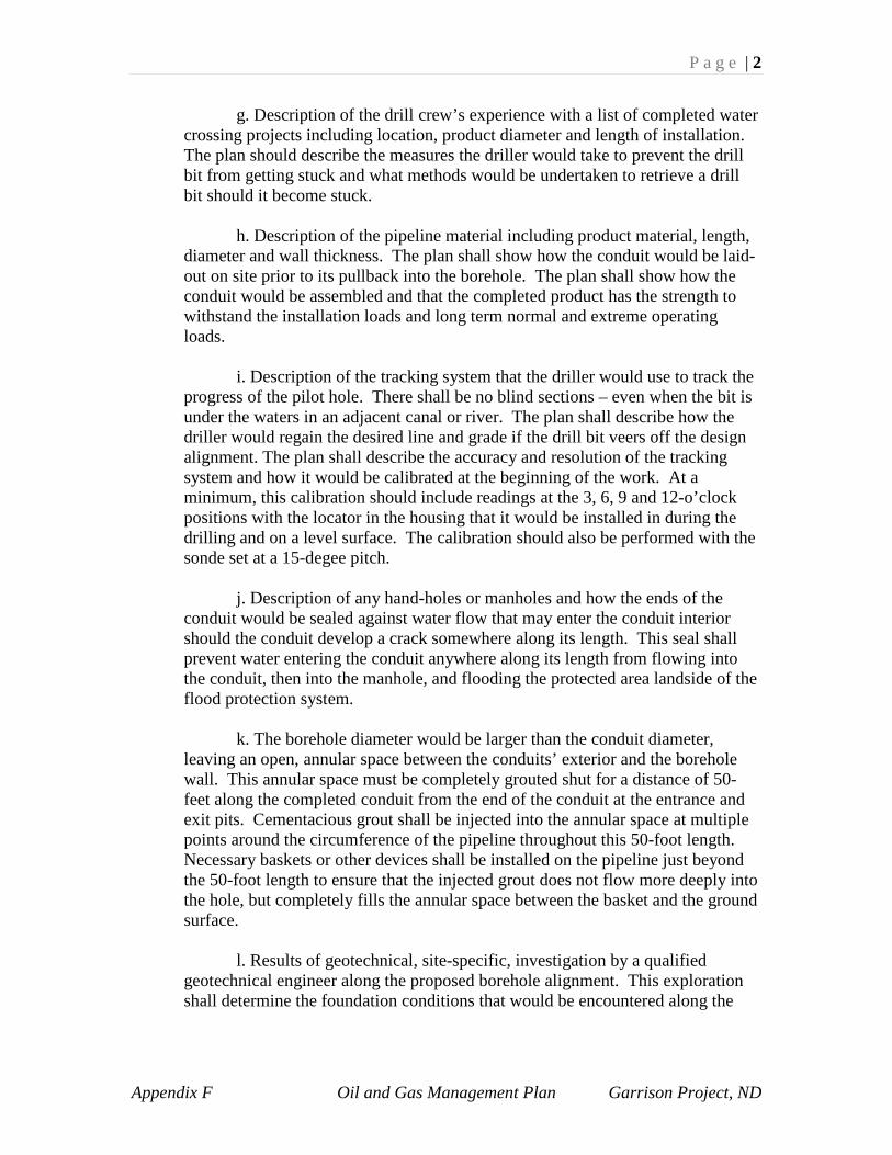
P a g e | 2
Appendix F Oil and Gas Management Plan Garrison Project, ND
g. Description of the drill crew’s experience with a list of completed water crossing projects including location, product diameter and length of installation. The plan should describe the measures the driller would take to prevent the drill bit from getting stuck and what methods would be undertaken to retrieve a drill bit should it become stuck.
h. Description of the pipeline material including product material, length,
diameter and wall thickness. The plan shall show how the conduit would be laid-out on site prior to its pullback into the borehole. The plan shall show how the conduit would be assembled and that the completed product has the strength to withstand the installation loads and long term normal and extreme operating loads.
i. Description of the tracking system that the driller would use to track the progress of the pilot hole. There shall be no blind sections – even when the bit is under the waters in an adjacent canal or river. The plan shall describe how the driller would regain the desired line and grade if the drill bit veers off the design alignment. The plan shall describe the accuracy and resolution of the tracking system and how it would be calibrated at the beginning of the work. At a minimum, this calibration should include readings at the 3, 6, 9 and 12-o’clock positions with the locator in the housing that it would be installed in during the drilling and on a level surface. The calibration should also be performed with the sonde set at a 15-degee pitch.
j. Description of any hand-holes or manholes and how the ends of the
conduit would be sealed against water flow that may enter the conduit interior should the conduit develop a crack somewhere along its length. This seal shall prevent water entering the conduit anywhere along its length from flowing into the conduit, then into the manhole, and flooding the protected area landside of the flood protection system.
k. The borehole diameter would be larger than the conduit diameter,
leaving an open, annular space between the conduits’ exterior and the borehole wall. This annular space must be completely grouted shut for a distance of 50-feet along the completed conduit from the end of the conduit at the entrance and exit pits. Cementacious grout shall be injected into the annular space at multiple points around the circumference of the pipeline throughout this 50-foot length. Necessary baskets or other devices shall be installed on the pipeline just beyond the 50-foot length to ensure that the injected grout does not flow more deeply into the hole, but completely fills the annular space between the basket and the ground surface.
l. Results of geotechnical, site-specific, investigation by a qualified
geotechnical engineer along the proposed borehole alignment. This exploration shall determine the foundation conditions that would be encountered along the

P a g e | 3
Appendix F Oil and Gas Management Plan Garrison Project, ND
designed drill path. The exploration should extend to 20-feet below the deepest part of the design drill path and should include:
The vertical and horizontal extents of subsurface strata, fill, debris. Standard penetration rates. The particle size distribution of coarse-grained soils. The plastic and liquid limits of fine-grained soils Water table levels. Areas of suspected and known contamination should be noted and
characterized.
These borings shall be backfilled after completion by tremie grouting, from the bottom up, with a neat cement grout. The grout shall consist of a mixture of 94 pounds of Type 1 Portland cement to no more than 6 gallons of water. Bentonite shall be added in proportion of 1% to 10% by weight of cement.
m. Backfill procedures for the entry and exit pit excavations. The backfill
material must be compacted to 95% of the Standard Proctor maximum dry density with moisture contents within 3% of the Standard Proctor optimum moisture content.
n. Delineation of all property interests in the area. If this work would take
place on Federal property, the owner must contact Mr. Tim Kolke, Real Estate, Garrison Project Corps of Engineers (701-654-7414 x235), to obtain a right of entry permit.
o. The exit and entrance pits at the ends of the design drill path shall be at least 300-feet landside of any landside levee toe and at least 50-feet riverside of any riverside levee toe. Where the design drill path is within 100-feet of either levee toe, the drill path shall be level and in rock or a minimum of 50-feet below the base of the flood protection system. p. Assessment of the maximum allowable residual mud pressures that the borehole wall can tolerate without hydrofracturing. The maximum allowable mud pressures can be estimated using the Delft equation and shall account for overburden pressure, soil type, shear strength and other geotechnical parameters.
q. During drilling, the actual residual pressure in the return mud flow shall be measured at a point behind the drill bit, but no further than 15 or 20-feet behind the drill bit. The pressure shall be measured continuously while drilling and there is a positive return mud flow. The pressure shall also be measured while drilling is paused and there is no return mud flow. The measured mud pressures shall be no more than one-half of the calculated maximum.

P a g e | 4
Appendix F Oil and Gas Management Plan Garrison Project, ND
r. The contractor shall provide proof that all measurement system (sensors, readout devices, etc) related to the horizontal/vertical control system and the drilling fluid pumping and pressure measurement system have been calibrated against appropriate national standards within the last 6-months.
s. Any misdirected or unsuccessful bores must be completely grouted shut with a cement-bentonite grout.
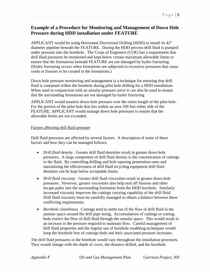
P a g e | 5
Appendix F Oil and Gas Management Plan Garrison Project, ND
Example of a Procedure for Monitoring and Management of Down Hole Pressure during HDD installation under FEATURE APPLICANT would be using Horizontal Directional Drilling (HDD) to install its 42” diameter pipeline beneath the FEATURE. During the HDD process drill fluid is pumped under pressure into the borehole. The Corps of Engineers (COE) has a requirement that drill fluid pressures be monitored and kept below certain maximum allowable limits to ensure that the formations beneath FEATURE are not damaged by hydro fracturing. (Hydro fracturing occurs when formations are subjected to excessive pressures that cause voids or fissures to be created in the formations.) Down hole pressure monitoring and management is a technique for ensuring that drill fluid is contained within the borehole during pilot hole drilling for a HDD installation. When used in conjunction with an annular pressure curve it can also be used to ensure that the surrounding formations are not damaged by hydro fracturing
APPLICANT would monitor down hole pressure over the entire length of the pilot hole. For the portion of the pilot hole that lies within an area 100 feet either side of the FEATURE, APPLICANT would manage down hole pressures to ensure that the allowable limits are not exceeded.
Factors affecting drill fluid pressure Drill fluid pressures are affected by several factors. A description of some of these factors and how they can be managed follows.
• Drill fluid density. Greater drill fluid densities result in greater down hole pressures. A large component of drill fluid density is the concentration of cuttings in the fluid. By controlling drilling and hole opening penetration rates and maximizing the effectiveness of drill fluid recycling equipment drill fluid densities can be kept below acceptable limits.
• Drill fluid viscosity. Greater drill fluid viscosities result in greater down hole pressures. However, greater viscosities also help seal off fissures and other escape paths into the surrounding formation from the HDD borehole. Similarly increased viscosity improves the cuttings carrying capability of the drill fluid. Drill fluid viscosity must be carefully managed to obtain a balance between these conflicting requirements.
• Borehole cleanliness. Cuttings tend to settle out of the flow of drill fluid in the annular space around the drill pipe string. Accumulations of cuttings or cutting beds restrict the flow of drill fluid through the annular space. This would result in an increase in the pressure required to maintain flow. Careful management of drill fluid properties and the regular use of borehole swabbing techniques would keep the borehole free of cuttings beds and their associated pressure increases.
The drill fluid pressures in the borehole would vary throughout the installation processes. They would change with the depth of cover, the distance drilled, and the borehole
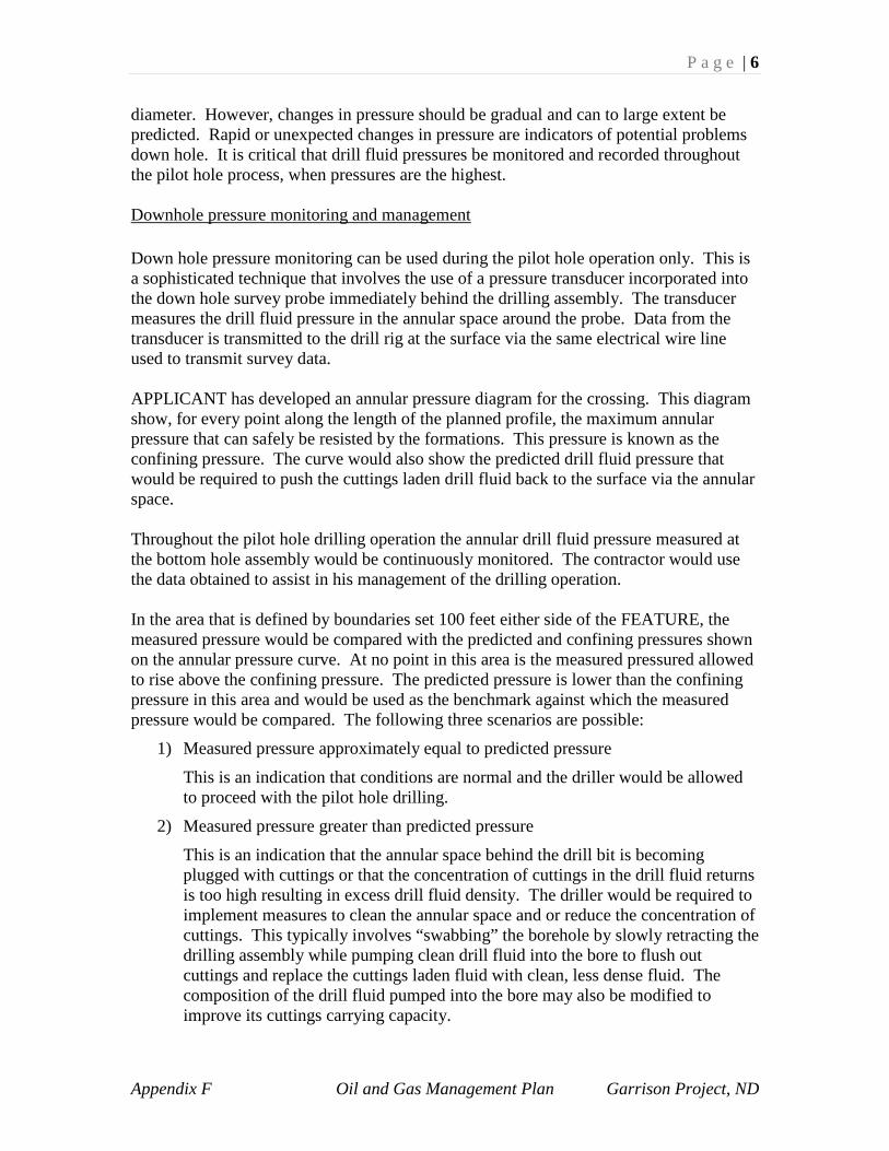
P a g e | 6
Appendix F Oil and Gas Management Plan Garrison Project, ND
diameter. However, changes in pressure should be gradual and can to large extent be predicted. Rapid or unexpected changes in pressure are indicators of potential problems down hole. It is critical that drill fluid pressures be monitored and recorded throughout the pilot hole process, when pressures are the highest. Downhole pressure monitoring and management Down hole pressure monitoring can be used during the pilot hole operation only. This is a sophisticated technique that involves the use of a pressure transducer incorporated into the down hole survey probe immediately behind the drilling assembly. The transducer measures the drill fluid pressure in the annular space around the probe. Data from the transducer is transmitted to the drill rig at the surface via the same electrical wire line used to transmit survey data. APPLICANT has developed an annular pressure diagram for the crossing. This diagram show, for every point along the length of the planned profile, the maximum annular pressure that can safely be resisted by the formations. This pressure is known as the confining pressure. The curve would also show the predicted drill fluid pressure that would be required to push the cuttings laden drill fluid back to the surface via the annular space. Throughout the pilot hole drilling operation the annular drill fluid pressure measured at the bottom hole assembly would be continuously monitored. The contractor would use the data obtained to assist in his management of the drilling operation. In the area that is defined by boundaries set 100 feet either side of the FEATURE, the measured pressure would be compared with the predicted and confining pressures shown on the annular pressure curve. At no point in this area is the measured pressured allowed to rise above the confining pressure. The predicted pressure is lower than the confining pressure in this area and would be used as the benchmark against which the measured pressure would be compared. The following three scenarios are possible:
1) Measured pressure approximately equal to predicted pressure
This is an indication that conditions are normal and the driller would be allowed to proceed with the pilot hole drilling.
2) Measured pressure greater than predicted pressure
This is an indication that the annular space behind the drill bit is becoming plugged with cuttings or that the concentration of cuttings in the drill fluid returns is too high resulting in excess drill fluid density. The driller would be required to implement measures to clean the annular space and or reduce the concentration of cuttings. This typically involves “swabbing” the borehole by slowly retracting the drilling assembly while pumping clean drill fluid into the bore to flush out cuttings and replace the cuttings laden fluid with clean, less dense fluid. The composition of the drill fluid pumped into the bore may also be modified to improve its cuttings carrying capacity.

P a g e | 7
Appendix F Oil and Gas Management Plan Garrison Project, ND
3) Measured pressure less than predicted pressure.
If the measured pressure is significantly less than the predicted pressure this is normally an indication that some of the drill fluid is escaping from the borehole. If the pressure drop is gradual and occurs over a significant length of the pilot hole it is an indication that the fluid is escaping from multiple points along the pilot hole. This type of release is due to the formation being too porous to allow the drill fluid to be contained rather than being due to hydro fracture.
If this is the result of a sudden drop in pressure it is an indication that fluid is escaping from the borehole in the immediate vicinity of the drilling assembly and that hydro fracturing may be occurring. In this event, the contractor would be required to implement measures to reduce or eliminate the loss of drill fluid from the borehole. One measure that may be implemented is the use of Lost Circulation Materials (LCM) to plug a fissure in the formation. The use of additives to improve the sealing properties of the drill fluid.
P a g e | 8
Appendix F Oil and Gas Management Plan Garrison Project, ND
Example of a horizontal drilling frac out plan SECTION 1 - INTRODUCTION In the HDD industry the term frac out is used to describe an inadvertent release of drill fluid resulting from the fluid escaping from an underground HDD borehole and rising to the surface above the borehole. The purpose of this document is to establish procedures for addressing potential impacts associated with a frac out of drilling fluid during the horizontal directional drill (HDD) process. In addition, this document establishes the criteria by which APPLICANT and appropriate agencies will determine when a proposed HDD is unsuccessful. The procedures and criteria described will generally apply to all HDD crossings on the project. Site-specific variations for crossings with more specific requirements will be described elsewhere. APPLICANT selected the HDD construction method to satisfy certain site-specific conditions for certain crossings. The APPLICANT will provide on-site environmental and construction inspection during the HDD process to keep adequate documentation, daily progress reports, as-built information, etc. SECTION 2 - HDD PROCESS Installation of an HDD crossing involves drilling an open borehole under an obstacle and the pulling a pipeline section into the borehole. There are three basic steps, or processes, that are executed in sequence: pilot hole, hole opening, and pullback. During all three processes drilling fluid is pumped into the borehole under pressure. This section addresses the HDD process. Pilot Hole Process The pilot hole is the first step in the HDD process. The pilot hole is drilled along a predetermined alignment and profile. The entry and exit points are located using traditional survey methods. The trajectory of the pilot hole is surveyed by two separate methods both of which employ a down hole survey tool referred to as a probe. The first method uses the earth’s natural magnetic field as a reference while the second method uses a system known as TruTracker that uses a wire coil on the surface that creates a magnetic field. After each section of the drill pipe has been drilled (approximately 30 feet), both methods of survey are used to calculate the pilot hole location. The pilot hole process consists of drilling a small diameter hole along the pre-determined alignment and profile. The pilot hole is drilled using either a jetting assembly or a down hole mud motor connected to a tri-cone rotary bit. Drilling fluid is pumped downhole via the string of drill pipe. The flow of drilling fluid powers the mud motor or jetting assembly that cuts the rock strata or soil. The fluid then flows back to the surface along the annular space between the drill pipe and the inside of the pilot hole. As it does so, the fluid also lubricates the drill stem, suspends and carries the drilled cuttings to the surface, and forms a wall cake to keep the hole open.

P a g e | 9
Appendix F Oil and Gas Management Plan Garrison Project, ND
Data obtained during the pilot hole process will aid the contractor in planning the details of subsequent phases of the installation. These data include the rate of penetration and the friction forces acting upon the drill string. More subjective data on the behavior of the drill string during the process is equally valuable. Hole Opening Process Once the pilot hole is complete the borehole diameter must be increased to allow it to accommodate the pipeline. Typically, the final borehole diameter is approximately 1-1/2 times the pipe diameter. The final borehole diameter is determined by the contractor and is dependent to a large degree on the length of the crossing and the types of geological formations through which the borehole passes. The borehole diameter is typically increased in several increments or passes. There are two types of downhole tools that are used: fly cutters, used for most soil formations, and rock hole opening tools, used for very dense soil or rock formations. Typically, the fly cutter or hole opening tool is attached to the drill pipe string that drilled the pilot hole and is then rotated and pulled back towards the drill rig from the entry point. A second drill rig or a track hoe is typically used to handle the drill pipe at the exit point. For each hole opening pass, as the fly cutter or hole opening tool progresses along the crossing profile, drill pipe is added to the string behind it while drill pipe is removed from the string ahead of it. Doing so maintains a continuous string of drill pipe in the borehole over its entire length. In soil formations, typically there will only be two or three hole opening passes. The first pass may be between a 24-inch- and a 30-inch-diameter fly cutter. Subsequent fly cutter passes will enlarge the hole to the desired diameter. Depending on the stability of the hole, the HDD contractor may use a barrel reamer, typically several inches smaller than the outside diameter of the final hole opening tool, and pull it through the hole immediately prior to pullback. This is typically referred to as a swab pass. The purpose of the swab pass is to ensure the establishment of a good drilling fluid wall cake, a clean hole, and a hole full of drilling fluid with the proper density. In rock formations, there will be several passes starting typically with a 22-inch-diameter hole opening tool and increasing in steps of 6-inch to 12-inch increments until the desired diameter is achieved. The diameter of each reaming pass is typically determined by the contractor based on field conditions. The drilling fluid serves continues to serve as a lubricant, facilitates the removal of cuttings, and stabilizes the borehole. Pullback Process The last step to complete a successful installation is the pullback of the prefabricated pipeline into the enlarged hole. A reinforced pull head is attached to the leading end of

P a g e | 10
Appendix F Oil and Gas Management Plan Garrison Project, ND
the pipe and to a swivel that is connected to a hole opener or fly cutter and the drill pipe. On the surface, the pipeline is supported with rollers as it is guided into the borehole. Once in the borehole the large diameter pipeline will be very buoyant in the drill fluid that occupies the borehole. The buoyancy will push the pipeline to the top of the borehole with considerable force. This will result in the following:
• A dramatic increase in the friction between the side of the borehole and the pipe.
• The possibility that the leading edge of the pull head could dislodge a cobble or rock fragment, binding the pipeline and making it possible to move the pipeline in either direction.
• The possibility that the external coating could be damaged by sharp and/or protruding material and highly abrasive material (coarse sands).
The buoyant force will be counteracted by adding water to the pipeline to increase its weight. The amount of water will be controlled to make the pipe as close to neutrally buoyant, or weightless, as possible. Drilling fluid The drilling fluid (also referred to as drilling mud) is made up primarily of water and bentonite. The concentration of bentonite typically varies between 0.24lb/gal and 0.36 lb/gal. Bentonite is a naturally occurring, non-toxic, inert clay that meets NSF/ANSI 60 NSF Drinking Water Additives Standards and is frequently used for drilling potable water wells. The environmental impact of a release of drilling fluid into a water body is a temporary increase in local turbidity until the drilling fluid dissipates with the current or is settles to the bottom. In the immediate vicinity of a release, benthic organisms may be smothered if sufficient quantities of bentonite settle upon them. Drill fluid is easily contained by standard erosion and sedimentation control measures such as stray bales and silt fence. Drill fluid would be contained on entry and exit worksites by hay bales and silt fence installed and maintained around the perimeter of each site. Within the boundaries of the worksites drill fluid would be controlled through the use of pits at the crossing entry and exit points and typical fluid handling equipment such as trash pumps. Drill fluid is released regularly on the drill rigs as part of normal operations when sections of drill pipe are separated. The worksite will be graded such that fluid released on the rig will flow into the fluid pit in front of the rig. Operating hours Due to issues associated with borehole stability for the large diameter boreholes required, it will be necessary for all HDD installation operations to be performed on a 24 hour per day, 7 day per week basis.

P a g e | 11
Appendix F Oil and Gas Management Plan Garrison Project, ND
SECTION 3 – FRAC OUT OF DRILLING FLUID Throughout the HDD process there is a loss of drilling fluid into the geologic formation through which the drill passes. In some cases, the drilling fluid may be forced to the surface resulting in what is commonly referred to as a frac out. Therefore, while the intent of the HDD method is to avoid surface disturbance, surface disturbance may occur when there is a frac out of drilling fluid. It is extremely important to note that a loss of drilling fluid into the formation is not necessarily an indication that a frac out has occurred or is about to occur. It is normal to lose a significant amount of fluid into the formation without ever having a frac out. In fact, in very soft ground formations or in highly fractured formations it is normal to lose all of the drill fluid pumped into the borehole without a frac out occurring. A frac out cannot occur unless drill fluid escapes from the borehole into the formation. Hence preventing and managing such escapes will in turn prevent and manage frac outs. Drilling fluid releases are typically caused by pressurization of the drill hole beyond the containment capability of the overburden soil material. In some cases, a frac out of drilling fluid can be caused by existing conditions in the geologic materials (e.g., fractures) even if the down hole pressures are low. Drill fluid pressures are generally the highest during the pilot hole process and hence it is this process that presents the greatest risk for a frac out. If a frac out occurs during the pilot hole it opens a path through the ground formation for drill fluid to escape during the subsequent processes. Hence frac outs are likely, at the same location during the hole opening and pullback process. Similarly, if the pilot hole process can be completed without a frac out, then it is likely that the entire installation can also be completed without a frac out. Considerations for preventing and managing frac outs are described below. Frac out prevention The risk of a frac out in a sensitive area can be mitigated through profile design and through implementation of specific measures throughout the installation process. Profile design The HDD profile is designed to minimize the potential for the release of drilling fluid in sensitive areas. The type of subsurface material and the depth of cover material are factors considered in developing the profile of an HDD crossing. Cohesive soils, such as clays, dense sands, and competent rock are considered ideal materials for containment of drill fluid. An industry recommended minimum depth of cover of 25 feet in cohesive soils should be maintained to provide a margin of safety against drilling fluid loss in sensitive areas. In non-cohesive soils, a greater depth of cover will be used. In the

P a g e | 12
Appendix F Oil and Gas Management Plan Garrison Project, ND
designs of all the HDD crossings, APPLICANT has used depths of cover well in excess of the recommended minimum. In the vicinity of the entry and exit points of the crossing the depth of cover will be minimal. It is probable and expected that frac outs will occur in these segments of the crossing. The crossings are designed such that these segments will be in upland areas. Preventative measures implemented during installation Key preventative measures implemented during installation are geared toward keeping the drill fluid contained in the borehole and preventing its escape to surrounding ground formations. This is accomplished through monitoring and management of drill fluid pressures and drill fluid volumes. Drill fluid pressure monitoring and management The APPLICANT will implement and down hole pressure monitoring and management program. This program is described in a separate document.
Drill fluid volume monitoring and management It is intuitive that if drill fluid is not allowed to escape from the borehole then the entire volume of fluid pumped downhole should return to the surface via the annular space. However, as described above, it is normal that a portion or all of the drill fluid will be lost to the surrounding formation. Nevertheless a program for monitoring and managing the volumes of drill fluid used will be beneficial in identifying sudden increases in the volume of fluid lost which could signal a potential frac out. Throughout the HDD processes the contractor will keep a running balance of the total volume of fluid pumped downhole and the total volume recovered from the return pits. The difference between these volumes will be the volume lost from the borehole. If the rate of loss of fluid is greater than expected or if it suddenly increases this could be an indication of a problem downhole. Measures to reduce the loss of fluid from the borehole would be implemented as described in previous paragraphs. Frac out management Management of frac outs is key to minimizing the environmental impact of an HDD crossing and ensuring its successful completion. Managing frac outs requires that appropriate equipment is available, that the frac outs are detected in a timely manner, and that appropriate procedures are used to minimize the volume of fluid released and its environmental impact. A discussion of these issues follows. Response Equipment Equipment for containing, controlling and cleaning up any drill fluid released during a frac out will be kept on site throughout the installation process. Heavy equipment not
P a g e | 13
Appendix F Oil and Gas Management Plan Garrison Project, ND
specifically designated for control and clean up of drill fluid such as backhoes will also be available on site. The following list identifies some materials and equipment that will be maintained at each HDD site in sufficient quantities to help ensure containment of frac outs of drilling fluid:
• Weed free straw or hay bales. • Sand bags • Stakes to secure bales. • Silt fence. • Shovels, rakes, brooms and buckets • Trash pumps and flexible hose • Light tower(s), so that cleanup work could continue after dark. • A boat with appropriate personal safety equipment at major water body crossings.
Monitoring and detection An obvious key to the timely detection of a frac out is monitoring of the surface above the HDD crossing for drill fluid. This is relatively easy to accomplish in upland areas during daylight hours. However, for large diameter pipelines such as the one proposed by the APPLICANT, the HDD process must be done on a 24 hour per day, 7-day per week basis. Visually detecting a frac out in a large waterbody or marshy area will be difficult, especially at night. Unfortunately the areas where the potential environmental impact of a frac out are greatest are wetlands and waterbodies. These areas will present the greatest challenge visual monitoring. The APPLICANT will employ a program of visually monitoring the ground above the HDD crossing for frac outs. However, this program will be supplemented by data from the downhole monitoring measures described above, namely pressure monitoring and volume monitoring. The downhole pressure is greatest in the vicinity of the downhole tool in all three of the HDD processes described above. If a frac out occurs it will initiate from the borehole in the immediate vicinity of the downhole tool. Hence, visual monitoring on the surface will be concentrated on the area above the downhole tool. Survey stakes will have been placed and labeled on the surface at 100-foot intervals along the HDD centerline. The monitors will be constant radio contact with the driller who will keep them apprised of the position of the downhole tool. The survey stakes will provide the monitors with the necessary reference to allow them to concentrate their efforts above the downhole tool. The driller will also keep the monitors apprised of the drill fluid pressures and mud volume balance and will provide his professional opinion of level of risk of a frac out occurring at any given time.

P a g e | 14
Appendix F Oil and Gas Management Plan Garrison Project, ND
Armed with this data the monitors will be able to decide if monitoring a difficult area, such as a deep swift river at night is warranted. It will also allow them to allocate their resources in the most effective manner. The identification of a potential frac out prior to it actually occurring is dependent upon the skill and experience of the people involved. For this reason, the APPLICANT will be using a contractor that specializes in HDD to perform the proposed crossings. Similarly the environmental inspector who will supervise monitoring and mitigation efforts will also be experienced in this type of work. Corrective Action for Frac outs If a frac out occurs the chief inspector and the environmental inspector will be immediately notified. The following describes the sequence of events that will then take place. Minimization of volume released. The first action required when a frac out is detected is to minimize the volume of drill fluid that is released. This will be done by immediately halting pumping of drill fluid downhole. Pumping will not resume until the situation is assessed and, if possible, the fluid release is contained and controlled. As it is probable that the frac out will resume as soon as fluid pumping starts again containment and control measures will have to be able to contend with a further release of fluid. Normally the frac out stops of its own accord when the drilling assembly progresses a short distance ahead of the release point. The risk of failure of the HDD installation increases dramatically as the duration over which pumping is halted increases. Hence, actions will be taken quickly in order that pumping may resume as quickly as possible. Containment and control of drill fluid released The types of measures implemented to contain the fluid released will depend on the type of area in which the release occurs. Upland areas - Frac outs in upland areas are most common as the drill profiles are designed such that the portions that have minimal depth of cover are beneath upland areas. Containment measures in these areas are easily implemented and consist of using hay bales, and or silt fence to contain the fluid within the immediate vicinity of the release. If the rate of release is large, a collection pit will be dug at the point of release and a trash pump will be set up to draw fluid from the pit and pump it back to the drill rig via a flexible hose. Once the containment measures are in place drilling operations will resume. Wetlands - Frac outs in wetlands are quite rare as the depth of cover provided in these areas is normally sufficient to prevent frac outs. If a frac out occurs the containment and control measures will be similar to those used in upland areas with the exception that the

P a g e | 15
Appendix F Oil and Gas Management Plan Garrison Project, ND
use of heavy equipment will be severely restricted. Once the containment measures are in place drilling operations will resume. Depending of the flow rate of fluid released, drilling procedures may be modified to reduce that rate. These modifications include introduction of LCM’s (Lost Circulation Material) into the drill fluid, increasing drill fluid viscosity and the temporary reduction of drill fluid pumping rates. Drill penetration rates may also be temporarily increased in an effort to move the drilling assembly away from the release point as quickly as possible in order that the release stops quickly. Waterbodies - Frac outs in waterbodies are also rare due to the provision of adequate depth of cover. Implementation of containment and control measures is most difficult in waterbodies and is only practicable when the depth of water is less than two feet and the water is slow moving. In these cases only, the drill fluid will be contained by hand carrying sand bags into the waterbody. A containment barrier that extends above the water surface will be built by hand placing the sand bags around the release point. If practicable, a trash pump will be placed on the shore and a suction hose extended from the pump to the release point. The drill fluid will then be pumped through a flexible hose back to the drill rig. Once the containment measures are in place drilling operations will resume. If a frac out occurs in a water body that is more than two feet in depth or has significant flow there is nothing that can be done to contain or control the drill fluid that has been released. Drilling operations will resume immediately and measures will be implemented to limit the further release of fluid into the waterbody. These include introduction of LCM’s into the drill fluid, increasing drill fluid viscosity and the temporary reduction of drill fluid pumping rates. Drill penetration rates will also be temporarily increased in an effort to move the drilling assembly away from the release point as quickly as possible in order that the release stops quickly. The effectiveness of the measures implemented to limit the release of drill fluid will be closely monitored. If the measures are not effective and if the environmental impact of the release is deemed unacceptable the HDD installation will be abandoned. Another attempt using a modified profile or at an alternate location may be made. The APPLICANT will notify appropriate downstream water intake authorities of the existence and location of any drill fluid plume that extends more than 1,000 yards from the HDD crossing site. Additional control measures A determination will be made of the cause of the frac out. If it is determined that downhole pressures are excessive then measures to reduce them will be implemented. These measures are described above and include swabbing the hole and or modifying the drill fluid properties.
P a g e | 16
Appendix F Oil and Gas Management Plan Garrison Project, ND
Drill fluid clean up Measures to clean up drill fluid released by a frac out will be determined on a case-by-case basis in consultation with the environmental inspector. Often, if the features affected are not sensitive and the volumes released are small minimal or no clean up will be required. Similarly, it is often determined that clean up measures will do more harm than good to sensitive features and that it is best to let the drill fluid dissipate naturally. Drill fluid can be cleaned up by collecting it by hand with shovels, brooms and buckets. Larger volumes can be cleaned up by means of pits and pumps or mechanized equipment. In wetland and upland areas drill fluid can be diluted by washing the affected area down with water. Agency Notification Procedures If a frac out occurs within a stream, wetland or wetland buffer, or other sensitive resources, or poses a threat to public safety, the Environmental Inspector will immediately notify Senior Environmental Specialist for the project. The Environmental Inspector will provide the following:
• The location of the frac out;
• A description of the area affected; and
• The containment measures implemented. As soon as possible, a report, containing the following information, will be prepared and emailed to the appropriate agencies.
• The cause of the release;
• Photographs of the release site;
• The area affected;
• The location and size of the resulting work area; and
• The location of any drainage, streams or wetlands in the area and the distance to them from the failure site.
Upon completion of HDD activities, the APPLICANT will prepare a report that summarizes:
• The events leading up to the frac out;
• The measures taken to minimize the impacts following the release;
• Any impacts from the release;
• Mitigation for the impacts from the release; and
• Agency contacts.

P a g e | 17
Appendix F Oil and Gas Management Plan Garrison Project, ND
Geotechnical Report Example An example of a geotechnical report can be obtained by contacting the Omaha District Office through the Garrison Project.

Appendix G Oil and Gas Management Plan Garrison Project, ND
APPENDIX G
Abbreviations and Terms

This space left blank intentionally.

Appendix G Oil and Gas Management Plan Garrison Project, ND
Oil and Gas Management Plan (O&GMP), pg1 U.S. Army Corps of Engineers (Corps), pg1 Garrison Dam/Lake Sakakawea Project (Garrison Project), pg1 Mean sea level (MSL), pg1 Bureau of Land Management (BLM), pg1 U.S. Forest Service (USFS), pg1 Mcf (thousand cubic feet), pg3 Four Bears Bridge (Highway 23), pg11 Garrison Dam/Lake Sakakawea Master Plan (Master Plan), pg17 North Dakota Industrial Commission’s Oil and Gas Division (NDOGD), pg26 North Dakota Department of Health (NDDH), pg26 National Environmental Policy Act (NEPA), pg27 Environmental Assessment (EA), pg28 Environmental Impact Statement (EIS), pg28 Surface Use Plan of Operation (SUPO), pg28 Spill Prevention, Control, and Countermeasure (SPCC) pg28 Environmental Protection Agency (EPA), pg28 Hydrogen Sulfide (H2S) Contingency Plan, pg29 U.S. Fish & Wildlife Service (USFWS), pg31 Environmental Protection Agency (EPA), pg31 North Dakota Department of Health (NDDH), pg31 North Dakota Department of Game and Fish (NDG&F), pg31 North Dakota State Historic Preservation Office (SHPO), pg31 Council on Environmental Quality’s (CEQ), pg31 Migratory Bird Treaty Act (MBTA), pg33 Endangered Species Act (ESA), pg33 Fish and Wildlife Coordination Act (FWCA), pg33 National Marine Fisheries Service (NMFS), pg33 American Indian Religious Freedom Act (AIRFA), pg34 Native American Grave Protection and Repatriation Act (NAGPRA) , pg34 Resource Conservation Recovery Act (RCRA), pg34 Occupational Health and Safety Administration (OSHA), pg34 Department of Transportation (DOT), pg34 Supervisory Control and Data Acquisition (SCADA), pg48 Horizontal Direction Drilling (HDD), pg49 Underground Injection Control (UIC), pg51 National Ambient Air Quality Standards (NAAQS), pg 57 Sulfur dioxide (SO2), pg57 Nitrogen dioxide (NO2), 57 Carbon monoxide (CO), pg57 Particulate matter (PM), pg57 Best management practices (BMP), pg61 Biological Assessment (BA), pg68 National Register of Historic Places (National Register), pg69 No Surface Occupancy (NSO), pg71 National Pollutant Discharge Elimination System (NPDES), pg74