gap analysis business impact of model driven …maguire/degree-project-reports/040402... · master...
TRANSCRIPT
Gap Analysis Business Impact ofModel Driven Architecture on Next
Generation Telemedicine ServiceProvision in the Home Healthcare
Sector
P A S C A L L A U E
Master of Science ThesisStockholm, Sweden 2004
IMIT/TSLAB-2004-03
A Case Study


Master Thesis Royal Institute of TechnologyGap Analysis Business Impact of Model Driven Architecture on Next Generation Telemedicine Service Provision in the Home Healthcare Sector
Pascal Laue [email protected]
i Version 1.0
Master Thesis Supervisors Master Thesis Examiner Kurt Lundgren IMIT/TS Royal Institute of Technology Stockholm, Sweden
Master Thesis Advisor Rustam Nabiev IMIT Royal Institute of Technology Stockholm, Sweden Master Thesis Industry Biomedical Engineering Supervisor Sven Jonsson MTA Huddinge University Hospital Huddinge, Sweden Master Thesis Industry Medical Information Systems Supervisor Daniel Andersson DIMIS Huddinge University Hospital Huddinge, Sweden Master Thesis Industry Technical Mentor, Associate Project Supervisor Model Driven Architecture (MDA), Enterprise Systems, and Platform Technologies Donald Baldwin Enterprise Systems Architecture Laboratory (ESAL) Auldenfire Sweden AB Stockholm, Sweden

Master Thesis Royal Institute of TechnologyGap Analysis Business Impact of Model Driven Architecture on Next Generation Telemedicine Service Provision in the Home Healthcare Sector
Pascal Laue [email protected]
ii Version 1.0
Master Thesis Royal Institute of TechnologyGap Analysis Business Impact of Model Driven Architecture on Next Generation Telemedicine Service Provision in the Home Healthcare Sector
Pascal Laue [email protected]
iii Version 1.0
Abstract
The need for improvement of existing business procedures leads often to the construction of a new IT system. Such a system needs to be analyzed with respect to its feasibility, business impact, and economical impact on the company. The vision of the future system needs to be translated into achievable goals. These can be compared to a benchmark describing the situation at the time being. A vertical gap analysis provides such a comparison focusing on the differences between the two systems. When the functionality of the system has been defined, several implementation approaches need to be considered and compared to each other in order to find the best one. A horizontal gap analysis can be used in this aim.
The application of both vertical and horizontal gap analyses within the framework of Model Driven Architecture is demonstrated on the TeleMed HC project at Huddinge University Hospital, building an EAI platform for remote monitoring of biomedical equipment located in patient homes. Keywords: Gap Analysis, Vertical Gap Analysis, Horizontal Gap Analysis,
Model Driven Architecture, Telemedicine, Enterprise Application Integration, System Architecture, Feasibility, Business Justification, Economic Justification, Decision Strategy, Risk Mitigation, Message-Oriented Middleware

Master Thesis Royal Institute of TechnologyGap Analysis Business Impact of Model Driven Architecture on Next Generation Telemedicine Service Provision in the Home Healthcare Sector
Pascal Laue [email protected]
iv Version 1.0
Acknowledgements
I would like to thank the following persons for their support:
Rustam Nabiev Royal Institute of Technology Kurt Lundgren Royal Institute of Technology Sven Jonsson Huddinge University Hospital Daniel Andersson Huddinge University Hospital Ola Gran Huddinge University Hospital Lars-Erik Hellberg Huddinge University Hospital Omar Arhzane Huddinge University Hospital Donald Baldwin Auldenfire Sweden AB Ulf Hedlund Auldenfire Sweden AB Henrik Jansson Oracle Svenska AB
Without them, this master thesis would never have been possible. I would also like to thank all the staff at MTA who has been of great help during this project and the Oracle support in Sweden, Belgium, Russia, and India for their great help with the installation of the Oracle products.

Master Thesis Royal Institute of TechnologyGap Analysis Business Impact of Model Driven Architecture on Next Generation Telemedicine Service Provision in the Home Healthcare Sector
Pascal Laue [email protected]
v Version 1.0
Table of Contents 1. Introduction 1
1.1 Overview 2
2. Background 2 2.1 Context 2 2.2 Telemedicine Services in the Home Healthcare Sector 3
2.2.1 Social Benefits 3 2.2.2 Phases 3 2.2.3 Business Model 3
2.3 Roles and Responsibilities 4
3. Purpose 5
4. Scope 6
5. Method, Models, and Standards 6 5.1 Method 6 5.2 Gap Analysis 6
5.2.1 Definition 6 5.2.2 Vertical and Horizontal Gap Analyses 7 5.2.3 Gap Analyses and Model Driven Architecture 8 5.2.4 Business Reasons for Using Gap Analyses 9
5.3 Model Driven Architecture 10 5.3.1 Core Concepts 10 5.3.2 MDA and the TeleMed HC Project 11 5.3.3 MDA and Agile Modeling 11
5.4 Organization and Deployment of MDA on TeleMed HC 11 5.4.1 Business Cycles 12 5.4.2 Standards Used in the TeleMed HC Project 12
6. Showcase: The TeleMed HC Project 13 6.1 The Impact of Using MDA – A Comparative Study 13 6.2 Decision Strategies 16
6.2.1 Architectural Decisions 16 6.2.2 Business Decisions 17 6.2.3 Risk Mitigation 17 6.2.4 Example 1 – Database: Architectural and Business Decision 18 6.2.5 Example 2 – Server Operating System: Business Decision 18 6.2.6 Example 3 – Message Queue: Architectural Decision 19 6.2.7 Example 4 – Application Server: Risk Mitigation Decision 20
6.3 Implications 22 6.3.1 Example – MOM vs. VPN 23
7. Conclusions 24 7.1 Conclusion 24 7.2 Future Work 26 7.3 Lessons Learned 26
7.3.1 CSD Project 26 7.3.2 Pilot Phase 26 7.3.3 Expectations and Outcomes 27 7.3.4 MDA, RUP, and AM 27

Master Thesis Royal Institute of TechnologyGap Analysis Business Impact of Model Driven Architecture on Next Generation Telemedicine Service Provision in the Home Healthcare Sector
Pascal Laue [email protected]
vi Version 1.0
8. Acronyms 28
9. References 29 9.1 Printed and Electronic Sources 29 9.2 Oral Sources 31
10. Appendices I 10.1 Appendix A: Agile Modeling Artifacts I 10.2 Appendix B: The Spiral Model II
List of Figures Figure 6-1 Comparison of Baselines and Results 16 Figure 6-2 TMHC Pilot System Conceptual Model 17 Figure 6-3 HGA: Oracle9iAS 21 Figure 6-4 HGA: JBoss 22 Figure 6-5 The Architecture of the VPN Approach 24 Figure 10-1 The Spiral Model II
List of Tables Table 2-1 Roles and Responsibilities [1] 5 Table 6-1 Baselines, Goals, and Outcomes of Phases 2 and 3 14 Table 6-2 Approximate Installation Times as Clocked (Italic: Estimated Values) [28] 15 Table 6-3 Horizontal Gap Analysis: Oracle9iAS vs. JBoss 21 Chapters 2.2, 7.3.1, and 7.3.2 were written by Andreas Larsson; chapters 5.4 and 7.3.3 by André Alander.
Master Thesis Royal Institute of TechnologyGap Analysis Business Impact of Model Driven Architecture on Next Generation Telemedicine Service Provision in the Home Healthcare Sector
Pascal Laue [email protected]
1 Version 1.0
1. Introduction New systems are usually built because a need has been identified for improving existing business procedures. When such needs are identified, automation of certain procedures is a common approach to improvement; however, such a new system should be analyzed with respect to:
• Feasibility: Is the proposed system feasible? If there is no technique currently available to build the envisioned system or if the available techniques are not mature enough yet, the system cannot be built.
• Business Justification: Does it make sense to build this system? Does this system add any value to the business of the company? A business justification can even exist if the system does not generate any monetary benefit; for example, a new healthcare system might improve the quality of life for a hospital’s patients without generating any monetary benefit for the hospital.
• Economic Justification: Is it profitable to build this system? Even if a new system improves the business procedures, it can prove more costly than the solution already in place. Therefore, a new system needs to be analyzed with respect to its:
o Total Cost of Ownership (TCO)
o Return on Investment (ROI)
o Future Value
When investigating the economic impact of a new system according to the criteria above, one possible outcome is that a project is cancelled already in the analysis phase because the envisioned solution cannot be justified economically.
In order to be able to compare any future solution to the solution in place at the time being, a benchmark needs to be established. This benchmark needs to describe the business procedures and workflows in place at the time being. Then, the envisioned solution needs to be sketched out and defined in terms of business procedures and workflows. Having defined these two benchmarks, a Vertical Gap Analysis (VGA) can be established comparing these two systems and investigating if the proposed system is feasible, if there exists any business justification for it, and if there exists any economic justification for it. To say it somewhat simplified: A VGA investigates if it is more profitable to do nothing (keep the status quo) or to do something (build a new system).
If the VGA shows that building a new system is worth the investment, different possible solutions should be compared to each other in order to find the one that is best suited. In order to be able to do so, a Platform Independent Model (PIM) describing the system to be built in a platform-independent manner needs to be established. This PIM will be mapped to several Platform Specific Models (PSMs) describing different possible technical implementations. These PSMs can then be compared to each other investigating their costs, strengths, weaknesses, problems, etc. Such a comparison is called a Horizontal Gap Analysis (HGA). This approach allows to compare different possible solutions before any commitment to a certain technology has been made, leaving all doors open. Now the best solution for the system to be built (and not for the system to be built given that product xyz or language xyz is used) can be chosen.
The concepts outlined above are being applied in a project called ‘Telemedicine Home Care’, short ‘TeleMed HC’, at Huddinge University Hospital, one of Sweden’s major hospitals located in the Stockholm region. The goal of the project is to build an Enterprise Application Integration (EAI) platform for remote monitoring of biomedical equipment located at patients’ homes.

Master Thesis Royal Institute of TechnologyGap Analysis Business Impact of Model Driven Architecture on Next Generation Telemedicine Service Provision in the Home Healthcare Sector
Pascal Laue [email protected]
2 Version 1.0
1.1 Overview The structure of this paper is as follows:
• Chapter 2 gives an introduction and an overview over the TeleMed HC project at Huddinge University Hospital.
• Chapters 3 and 4 describe the purpose and scope of this paper.
• Chapter 5 describes the method, models, and standards used in the paper and the TeleMed HC project. After a description of the method, it provides an introduction to the concept of the Gap Analysis It gives a definition of the term, explains the concepts of vertical and horizontal gap analyses and how they fit into the framework of MDA, and states their expected business impact. Then it describes MDA and how MDA has been applied in the TeleMed HC project.
• Chapter 6 analyzes the impact of MDA in general on the TeleMed HC project by comparing the pilot phase to the proof-of-concept phase. It then describes several decision strategies used when having to choose between different implementation approaches and what impact horizontal gap analyses had on the choice of strategy, illustrated by several examples. Finally, the implications of such decisions on the TeleMed HC project will be analyzed with respect to the long-term strategies for this system, updating the vertical gap analysis established during the proof-of-concept phase.
• Chapter 7 draws the conclusions from the analysis of the results in chapter 6. It analyzes the business impact realized by the use of gap analyses together with MDA in the TeleMed HC project and compares it to the expectations stated in chapter 5. Based on those results, areas of further work are proposed.
2. Background This chapter gives an introduction to the TeleMed HC project.
2.1 Context “At Karolinska University Hospital, Huddinge (KUS HS), the Department of Innovation and Medical Information Systems, amongst other things, runs a joint development project with the Biomedical Engineering Department (MTA), within one of its program offices; Telemedicine. The aim is to create a system for management and support of biomedical devices located in patient homes. Other initiatives include, but are not limited to, providing remote ECG diagnostic services for the remote island of Gotland (56,000 inhabitants).
One of the departments’ long-term goals, within the area of Telemedicine/eHealth/Biomedical Engineering, is to provide a platform which can integrate different disparate services offered by the hospital – regionally, nationally, and worldwide.
To be able to reach their long-term goal, the departments are seeking to develop partnership programs together with both the academia and the industry. Involving students, researchers, and IT-industry professionals creates a win-win situation, where it is possible for the academia to get access to a research field within the area of applied Telemedicine/eHealth, the IT- and biomedical professionals to develop new products and services, and the hospital to get access to high value-added competence at a reasonable cost creating new opportunities for clinical IT-based solutions benefiting both the patients and the clinicians.” [17]
One of these partnership programs is TeleMed HC, a project initiated and owned by Huddinge University Hospital.
On January 1, 2004, Huddinge University Hospital (HS) was merged with Karolinska Hospital (KS) into what is now known as Karolinska University Hospital (KUS). When differentiating between the two

Master Thesis Royal Institute of TechnologyGap Analysis Business Impact of Model Driven Architecture on Next Generation Telemedicine Service Provision in the Home Healthcare Sector
Pascal Laue [email protected]
3 Version 1.0
hospitals, HS is referred to as Karolinska University Hospital, Huddinge (KUS HS) and KS as Karolinska University Hospital, Solna (KUS KS). As the work described in this paper was performed before the merger and in order not to introduce more confusion than necessary, the old name (Huddinge University Hospital) and acronym (HS) will be used throughout the rest of this document.
2.2 Telemedicine Services in the Home Healthcare Sector The density of biomedical equipment in the home environment has increased rapidly during the last decade. As new treatment methods develop and existing methods are refined, the complexity of these devices has increased. Using biomedical devices in the patient home environment is an effective mechanism in maintaining patient quality of life and is more effective in the utilization of patient care resources and funding.
The Biomedical Engineering Department (MTA) at Huddinge University Hospital (HS) is responsible for the maintenance of biomedical equipments. At the MTA, the number of home healthcare devices has increased from 40 pieces of equipment in 1990 to 2,300 units in 2000 [33]. The purpose of the TeleMed HC project is to enable the MTA business unit to support a greater number and variety of biomedical devices while minimizing the requirement for additional staffing and funding at an operational delivery level.
2.2.1 Social Benefits Benefits to patients utilizing telemedicine services can be divided into three areas [33]:
• Increased quality of life for patients
• Increased medical information level of patients – ability to provide better care
• Increased technical quality support for patients – ability to support devices better in the field
These benefits for the patients together with the economical benefits towards HS and MTA described in the Cost and Benefit Analysis paper [26] justify the continuation of this project and take it to the next level, the pilot stage.
2.2.2 Phases Pre-Study [33] 2002-08-01 – 2003-01-01 The pre-study was initiated by Daniel Andersson (DIMIS) and performed by Rustam Nabiev (KTH, Master of Science Thesis Work). The pre-study investigated the need for a Telemedicine system at MTA and the different approaches of developing such a system.
Proof of Concept [2] 2003-01-25 – 2003-06-01 Six KTH students performed the proof of concept as a part of the course Communication System Design (CSD). The pre-study was used as a basis for building a proof-of-concept vertical application prototype.
Pilot Stage 2003-08-15 – 2003-12-15 Phase three of the TeleMed HC Program is the case study described in this thesis paper. Three of the students involved in the proof-of-concept phase continued on into the development of a telemedicine pilot system. Based on lessons learned during the proof of concept, a different approach to the system’s design was taken. Instead of building a vertical application, it was decided to build a telemedicine platform, which any telemedicine application can run on top of. In addition to the platform, a patient application for transmission of data from the biomedical devices located in patient homes to the hospital was built.
Application Development 2004-01-19 – 2004-05-31 During phase four, six new students from KTH will refine the patient application built during the pilot phase and build another application intended for use at the hospital.
2.2.3 Business Model Several different perspectives can be found when analyzing the economic potential of this project. We have

Master Thesis Royal Institute of TechnologyGap Analysis Business Impact of Model Driven Architecture on Next Generation Telemedicine Service Provision in the Home Healthcare Sector
Pascal Laue [email protected]
4 Version 1.0
identified four different business models that each can produce a revenue stream, and/or release resources for the actors involved.
Integrate or build external applications to the platform This is what our main focus has been so far. Building applications aimed towards patients’ premises can be financially profitable in terms of lower maintenance costs and by relocating patients from the hospital to their homes. These applications can be sold to other users of the Telemedicine platform.
Integrate internal applications to the platform Existing applications at HS can be integrated to support the telemedicine platform and new applications can be built. These applications can be sold to other users of the telemedicine platform.
Sell a packaged system to other hospitals A complete system including the platform and applications can be sold to other hospitals in Sweden or in other countries. Besides revenues from the system itself, education of the staff and integration of existing systems have potential to create further income sources.
Outsource telemedicine service to other hospitals The platform can be built to support far more users than HS potentially can handle (because of e.g. geographical reasons). This leaves room for the hospital to outsource telemedicine services from other hospitals.
2.3 Roles and Responsibilities During the Pilot phase, the roles and responsibilities were distributes as described in this chapter. At the end of this phase, those were changed, and the new distribution can be found in [17].
Table 2-1 below identifies the organizational units that were responsible for each of the disciplines, workflow details, and supporting processes.
Roles & Person Responsibilities
Technical Project Manager • Donald Baldwin
The Project Manager role plans, manages and allocates resources, shapes priorities, coordinates interactions with customers and users, and keeps the project team focused. The Project Manager also establishes a set of practices that ensure the integrity and quality of project artifacts, as described in the Rational Unified Process [39]. Responsible for managing the overall Project Management discipline. Leads the extended Project Management Team
Designer • Andre Alander • Andreas Larsson • Pascal Laue
The designer role is responsible for designing a part of the system, within the constraints of the requirements, architecture, and development process for the project. The designer identifies and defines the responsibilities, operations, attributes, and relationships of design elements. The designer ensures that the design is consistent with the software architecture, and is detailed to a point where implementation can proceed.
Business Analyst • Andre Alander • Andreas Larsson • Pascal Laue
This role specifies the workflow of business use cases in terms of business workers and business entities. It also distributes the behavior to these business workers and business entities – defining their responsibilities, operations, attributes, and relationships.

Master Thesis Royal Institute of TechnologyGap Analysis Business Impact of Model Driven Architecture on Next Generation Telemedicine Service Provision in the Home Healthcare Sector
Pascal Laue [email protected]
5 Version 1.0
Software Architect • Donald Baldwin
The software architect role is responsible for the software architecture, which includes the key technical decisions that constrain the overall design and implementation for the project. The software architect has overall responsibility for driving the major technical decisions, expressed as the software architecture. This typically includes identifying and documenting the architecturally significant aspects of the system, including requirements, design, implementation, and deployment “views” of the system. The architect is also responsible for providing rationale for these decisions, balancing the concerns of the various stakeholders, driving down technical risks, and ensuring that decisions are effectively communicated, validated, and adhered to.
Implementer • Andre Alander • Andreas Larsson • Pascal Laue
The implementer role is responsible for developing and testing components, in accordance with the project’s adopted standards, for integration into larger subsystems. When test components, such as drivers or stubs, must be created to support testing, the implementer is also responsible for developing and testing the test components and corresponding subsystems.
System Analyst • Andre Alander • Andreas Larsson • Pascal Laue
The System Analyst role leads and coordinates requirements elicitation and use-case modeling by outlining the system’s functionality and delimiting the system; for example, identifying what actors exist and what use cases they will require when interacting with the system.
System Administrator • Andre Alander • Andreas Larsson • Pascal Laue
An individual taking on the role of System Administrator needs a good understanding of the specific hardware and software components used on a project, and the possible dependencies between these components.
Test Analyst • Andre Alander • Andreas Larsson • Pascal Laue
The Test Analyst role is responsible for identifying and defining the required tests, monitoring detailed testing progress and results in each test cycle and evaluating the overall quality experienced as a result of testing activities. The role typically carries the responsibility for appropriately representing the needs of stakeholders that do not have direct or regular representation on the project.
Table 2-1 Roles and Responsibilities [1]
Sven Jonsson was co-project manager, responsible for the MTA application, and Daniel Andersson was co-project manager, responsible for the platform development. Ola Gran was the project manager, reporting to a steering group [1]. As mentioned earlier, the project organization, roles, and responsibilities were changed after the pilot phase, and the new ones are described in [17].
3. Purpose The goal of this paper is to find out what business impact the use of gap analyses within the framework of MDA has. The application of vertical and horizontal gap analyses within the TeleMed HC project serves as a showcase, demonstrating their impact on architectural, business, and risk-mitigation decisions.
A second purpose of this paper is to analyze and — if possible — show how MDA can be used to reduce project risk by abstracting away functionality from its implementation, making it possible to exchange system components without affecting other components or the system’s overall functionality.

Master Thesis Royal Institute of TechnologyGap Analysis Business Impact of Model Driven Architecture on Next Generation Telemedicine Service Provision in the Home Healthcare Sector
Pascal Laue [email protected]
6 Version 1.0
4. Scope The focus mainly lies on the application of horizontal gap analyses. This kind of gap analysis is a fairly new concept introduced by Auldenfire [9]. It has so far been applied in several projects, but its business impact has not been analyzed and described in a scientific way, yet.
This paper concentrates on (1) the impacts that the use of gap analyses and Model Driven Architecture has on architectural decisions, and (2) the business implications of those impacts, by applying those tools and models on the TeleMed HC project. It does not, however, analyze how business processes can be re-engineered after introduction of the TeleMed HC system, adapting to the technical changes.
It is not a primary goal of this paper to demonstrate the impact of using any particular methodology or architectural framework other than Model Driven Architecture, even if they may be discussed.
5. Method, Models, and Standards
5.1 Method Already from the beginning it was clear that object-oriented analysis and design (OOAD), UML, and MDA would be used throughout this project phase. Even though it had not been decided formally yet, the implementation approach was leaning towards the use of a platform-centered one, using message-oriented middleware for the communication between the applications and the application server/data repository. The pilot phase started with some weeks of intensive training and reading to deepen, refresh, or adopt knowledge about UML, MDA, OOAD techniques, software architecture frameworks, OMG initiatives and standards, middleware, and more. Another important task during the summer was the set-up of the development environment. During the same time, I tried to find as much information as possible about gap analyses, but the result was more than poor: there was hardly anything that had to do with the kinds of gap analyses I was going to use. As a result of this, chapter 5.2 is entirely based on Auldenfire’s approach to using gap analyses.
After those introductory weeks, a stripped-down version of the RUP, adapted to the AM approach the project team intended to use, was introduced. This gave the project an overall structure and provided a standard documentation format. Using this structure implied also that the spiral model was going to be used for incremental development, meaning that we would have several iteration of each phase, adding more detail and/or functionality with every iteration.
When major decisions had to be taken, such as whether to take a VPN approach or using message-oriented middleware, it was my job to search for information about the different possibilities, to use gap analyses to compare them and judge their business impact, and to write a presentation about my findings that could be used as a decision base.
5.2 Gap Analysis Considering the different definitions of the term ‘Gap Analysis’ used in the industry (have a look at [8], [30], [37], [38], and [40] for some examples), it is necessary to state what kind of definition is going to be used throughout this paper, avoiding ambiguities. Having agreed on the definition, the concepts of vertical and horizontal gap analyses are introduced and it will be shown how they fit into the MDA framework. However, even a brilliant technical concept needs a business reason in order to be useful.
5.2.1 Definition “Gap Analysis – An analysis process which takes the organization’s vision and translates it into an achievable goal. This goal is then compared to the current organizational state to form a baseline (which represents the current state of the organization from both an IT and an operational perspective). The baseline is then used to measure the changes that must be implemented in order to achieve the goal.” [8]
Master Thesis Royal Institute of TechnologyGap Analysis Business Impact of Model Driven Architecture on Next Generation Telemedicine Service Provision in the Home Healthcare Sector
Pascal Laue [email protected]
7 Version 1.0
Establishing such a benchmark is important because changes to the IT system will almost always impact the way a company’s daily business is run. Once the benchmark is established and the achievable goal is agreed upon, a comparison of them will show if the system in question:
• Is feasible
• Has a business justification
• Has an economical justification
A system should only be built if it satisfies all three concerns above. A system that e.g. is feasible and has a business justification but decreases the income of the company should most likely not be built.
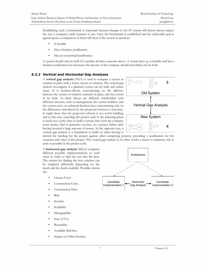
5.2.2 Vertical and Horizontal Gap Analyses A vertical gap analysis (VGA) is used to compare a system or solution in place with a future system or solution. The vertical gap analysis investigates if a planned system can be built and makes sense. It is business-driven, concentrating on the differences between the system or solution currently in place, and the system to be built. As there always are different stakeholders with different interests, such as management, the system builders, and the system users, an unbiased decision base concentrating only on the differences introduced by the proposed solution is necessary. It might show that the proposed solution is not worth building, and in this case, canceling the project early in the planning phase is much less costly than to build a system that costs the company more money than it generates revenue, or a project failure after having invested a large amount of money. In the opposite case, a vertical gap analysis is a foundation to build on when having to defend the funding for the project against other competing projects, providing a justification for the existence and value of this project. The vertical gap analysis is, in other words, a means to minimize risk as early as possible in the project cycle.
A horizontal gap analysis (HGA) compares different possible implementations to each other in order to find the one that fits best. The criteria for finding the best solution can be weighted differently depending on the needs and the funds available. Possible criteria are:
• License Costs
• Construction Costs
• Construction Time
• Risk
• Security
• Scalability
• Manageability
• Ease of Use
• Reusability
• Available Skill Sets
• Impact on Other Systems
Master Thesis Royal Institute of TechnologyGap Analysis Business Impact of Model Driven Architecture on Next Generation Telemedicine Service Provision in the Home Healthcare Sector
Pascal Laue [email protected]
8 Version 1.0
Usually, those criteria can be split up into technical and business criteria, where the later ones can be reduced to the following three:
• Total Cost of Ownership (TCO)
• Return on Investment (ROI)
• Future Value
Depending on the chosen criteria, a solution is selected and implemented. The horizontal gap analysis lets the management choose the best possible solution among all possible ones, providing an unbiased decision base. The horizontal gap analysis is also a powerful tool to analyze and control the project. Showing up the differences between the investigated solutions, it allows the project management to mitigate risk and control the costs incurred. It also provides a tool for the control of vendor influence: vendors tend to maximize their profit and to minimize their costs, trying to make their own products look better than competing ones. In other words, a vendor’s best interest is not necessarily the customer’s best interest. Without an objective comparison of the available COTS products available for the required functionality, it is hard to take an optimal decision. A horizontal gap analysis can provide such a comparison.
Another important advantage using a horizontal gap analysis is that in many cases, the preferred technical approach is not identical to the preferred business approach. In the ideal case, those approaches are identical, but often they are not. Applying a horizontal gap analysis helps to identify this issue and to quantify the different technical approaches into monetary issues. Quantification of the problem analyzing the short- and long-term impacts will help to take the best possible decision.
Why two different kinds of gap analyses? Vertical and horizontal gap analyses are independent of each other and are used in different phases of the project cycle. The vertical GA is used early in the project cycle in order to determine if the project is feasible and useful or if it should be canceled. Having passed that stage, the new system’s functionality must be defined independently from the way this functionality is going to be implemented. Only having done that, a horizontal GA can be used to compare different possible specific implementations of the specified functionality in terms of hardware platforms, programming languages, middleware, and so on. In terms of MDA, the horizontal GA is a tool that provides a decision base to take the step from a platform independent model (PIM) to a platform specific model (PSM).
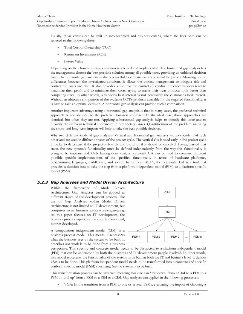
5.2.3 Gap Analyses and Model Driven Architecture Within the framework of Model Driven Architecture, Gap Analyses can be applied at different stages of the development process. The use of Gap Analyses within Model Driven Architecture is not limited to IT development, but comprises even business process re-engineering. As this paper focuses on IT development, the business process aspect will be shortly mentioned, but not developed.
A computation independent model (CIM) is a business process model. This means, it represents what the business sees of the system to be built. It describes how work is to be done from a business perspective. This specific and concrete model needs to be abstracted to a platform independent model (PIM) that can be understood by both the business and IT development people involved. In other words, this model represents the functionality of the system to be built at both the IT and business level. It defines what is to be done. This platform independent model needs to be transformed into a concrete and specific platform specific model (PSM) specifying how the system is to be built.
This transformation process can be inversed, meaning that one can ‘drill down’ from a CIM to a PIM to a PSM or ‘drill up’ from a PSM to a PIM to a CIM. Gap analyses can applied in the following processes:
• VGA: In the transition from a PIM to one or several PSMs, evaluating the impact of choosing a

Master Thesis Royal Institute of TechnologyGap Analysis Business Impact of Model Driven Architecture on Next Generation Telemedicine Service Provision in the Home Healthcare Sector
Pascal Laue [email protected]
9 Version 1.0
certain PSM on the system’s feasibility, business justification, and economical justification. This application is a refinement of the VGA established earlier in the project (see below)
• VGA: In the transition from a PIM to one or several CIMs, evaluating one or several business processes (will not be discussed in this paper)
• HGA: Comparison of different PSMs
• HGA: Comparison of different CIMs (will not be discussed in this paper).
A vertical gap analysis can be applied as soon as a Platform Independent Model (PIM) has been established for the system to be built. The PIM describes the system to be built in terms that can be understood by both business and IT development staff and allows comparing it to the system in place. One could also establish a vertical GA after having established a Computation Independent Model (CIM) in order to see if the system has a business and economic justification, and extend this vertical GA when the PIM was established in order to see if the system can be built using the chosen (platform independent) architecture. This would allow canceling the project with no more harm done than necessary at several points in time if necessary.
Once a PIM has been established and a vertical gap analysis has shown that the system is feasible and has both a business and economical justification, several Platform Specific Models are established. These models map the functionality defined in the PIM to specific code components, commercial off-the-shelf (COTS) products, nodes, and so on. For most systems, there are different possible programming languages, combinations of COTS components, and other system parts, that form candidate PSMs. These PSMs need to be compared to each other in order to find the one that fits the customer’s needs and goals best – a horizontal gap analysis. It is important to realize that whenever a system is designed, there is a point in time where the specification of platform independent functionality has come to the finest possible granularity and a decision needs to be taken on how to implement this functionality in a platform dependent way. At this point in time, a horizontal gap analysis helps to take the right decision, concentrating all available information to base a decision on. The advantage of this approach is that it provides a one-to-one mapping from the PIM to the different PSMs which offers a unique advantage over less explicit approaches. A quick look at the PIM and a PSM reveals which functionality has been mapped to which component. The use of a horizontal gap analysis concentrates all the decision taking process on how to implement the system at a single point in time, avoiding bad surprises at a later point in time, discovering that the chosen solution provides the required functionality but is not scalable enough, for example.
5.2.4 Business Reasons for Using Gap Analyses Gap analyses are a powerful tool for risk mitigation. In order to be able to perform a vertical gap analysis, clear project goal must be set. Setting clear goals is an important step on the way to a successful project – if no goals are set, they can simply not be met, either.
Having established one or several PIMs, a vertical GA allows identifying the impact of change to the system in place and judging the feasibility of an envisioned solution. It provides a measure of the business impact and economic justification of the future system in terms of optimization of ROI, total cost of ownership, and future value of the system. In other words: a vertical GA provides a measure on whether it is worth building the system in question or not.
A horizontal GA on the other hand allows comparing functionality and cost of different technical

Master Thesis Royal Institute of TechnologyGap Analysis Business Impact of Model Driven Architecture on Next Generation Telemedicine Service Provision in the Home Healthcare Sector
Pascal Laue [email protected]
10 Version 1.0
approaches before any financial commitment towards any of the proposed solutions has been made. This allows for selecting the optimal technology for the problem in question and to prepare different implementation approaches. The strength of a horizontal gap analysis is that every potential solution – or every PSM – can be mapped directly to the PIM. This implies that the transition from the platform independent architecture to the platform specific solution is neat and fully transparent – every component in the PSM can be mapped directly to a component in the PIM. This approach highlights both strengths and holes or weaknesses in certain implementations. In this way, the optimal technology can be chosen and a risk mitigation plan be established, eliminating the risk of being surprised unprepared by the discovery of weaknesses of a certain technology or product after a commitment to it. During the selection of a PSM, the vertical gap analysis should be extended to comprise the different implementations in order to analyze if they truly fulfill the set goals and to compare the impact on the economic justification of selecting a specific implementation.
5.3 Model Driven Architecture The Model Driven Architecture (MDA) is an emerging standard defined by the Object Management Group (OMG). “The MDA defines an approach to IT system specification that separates the specification of system functionality from the specification of the implementation of that functionality on a specific technology platform.” [31] This approach allows defining a system’s functionality independently from the restrictions a specific technological platform might impose. Once the system’s functionality is specified in a platform independent way, it can be implemented on several different platforms.
5.3.1 Core Concepts The MDA defines three core concepts:
• Models: “In the MDA, a model is a representation of a part of the function, structure and/or behavior of a system.” [31] Models are written in a formal specification language such as the Unified Modeling Language (UML) or the Interface Definition Language (IDL).
• Abstraction, Refinement, and Viewpoint: Abstraction is defined as the suppression of irrelevant detail. Abstraction criteria are used to determine what is included in a model. “A model that is based on specific abstraction criteria is often referred to as a model from the viewpoint defined by those criteria, or in short as a view of the system.” [31] Models can describe a system at a higher or a lower level of abstraction, i.e. hiding or showing more details of the system. Some pairs of such models are in a refinement relationship with each other: the more abstract one is called the abstraction, and the more specific one is called the realization.
• “Zooming” in and out: The MDA permits zooming in and out of a model showing objects or interactions. Zooming out is defined as going from a more detailed model to a more abstract model to hide the details, and zooming in is defined as going from a more abstract model to a more detailed level to see those details. Zooming in or out may result in multiple alternative models.
The MDA defines two different sorts of models written in UML: Platform Independent Models (PIMs) and Platform Specific Models (PSMs). A PIM provides the formal specifications of the structure and the functionality of the system abstracting away technical details. As its name suggests, it describes the components and their interactions in a platform-independent way. A PIM is based on a computations independent business model, referred to as Computation Independent Model (CIM). One PIM can be transformed to one or several PSMs specifying the implementation of the PIM on a specific platform. There are 4 different transitions defined involving PIMs and PSMs:
• PIM to PIM: Platform Independent Models can exist at different levels of abstraction. In order to be able to abstract out unnecessary detail or to refine a model in order to be able to map it to a PSM, a PIM can be transformed to another PIM at a different level of abstraction.

Master Thesis Royal Institute of TechnologyGap Analysis Business Impact of Model Driven Architecture on Next Generation Telemedicine Service Provision in the Home Healthcare Sector
Pascal Laue [email protected]
11 Version 1.0
• PIM to PSM: When a PIM has come to a level of great enough detail, it can be mapped to one or several PSMs.
• PSM to PSM: Platform Specific Models can, just like PIMs, exist at different levels of abstraction. PSMs can be refined in order to adapt a model to the use of a certain platform, operating system, programming language etc, and abstracted in order to get rid of unnecessary detail.
• PSM to PIM: A PSM can be mapped to one or several PIMs. This transformation is required if an existing implementation needs to be abstracted into a platform-independent model.
5.3.2 MDA and the TeleMed HC Project During the prototype stage of the project, a business analysis [24] was carried out. This analysis contained on one hand a baseline describing the situation and the workflows at the time being, and on the other hand a description of the situation and the workflows with the future system in place. A vertical gap analysis was established describing the differences between the actual and the future situation. Furthermore, the business drivers and the return on investment for both the cases that (1) no new system was built and (2) the new system was built and introduced within a time span of three years were investigated.
When it came to designing and building the proof-of-concept prototype, object-oriented design techniques were used, but not MDA. During the pilot stage, however, an MDA approach to system design was used from the beginning. UML use case models were constructed to describe the behavior and functionality of the system to build in a platform-independent way. This PIM was then used to establish several PSMs and a horizontal gap analysis was used to compare different candidate solutions. Based on this horizontal gap analysis, a certain approach was chosen for the implementation of the pilot system.
5.3.3 MDA and Agile Modeling In the TeleMed HC project, Agile Modeling [6] (AM) was used within the MDA framework. The use of AM reduces risk by providing enough structure to keep the development on track without letting the documentation efforts go overboard. AM focuses on collaboration between developers, the development of working software, collaboration with the customers, and quick response to changes. In terms of the TeleMed HC project, this meant that:
• The project team needed to be able to cooperate in order to build the best possible solution; the tools and processes used were important, but secondary.
• The software that was going to be built had to work in the first place; to document it comprehensively was important, but secondary.
• The collaboration with the users of the system, i.e. the patients, the engineers, and the doctors using it, etc., was more important than writing a contract and stick to it; a contract was never allowed to become a substitution for communication. Actually, good communication with the different project stakeholders was of outmost importance to make sure that the right system was built.
• Last but not least, the project team had to be able to react to changes in the business logic affecting the system during its development, and the code had to be designed to adapt easily to those changes. Being able to adapt the system to changes was more important than to follow a strict plan, even though having a well-defined project plan was important for controlling the project and its progress.
5.4 Organization and Deployment of MDA on TeleMed HC The infrastructure necessary for the TeleMed HC project was based on effective software engineering practice and building standardized management processes. This chapter describes the international standards used in this case study.
Master Thesis Royal Institute of TechnologyGap Analysis Business Impact of Model Driven Architecture on Next Generation Telemedicine Service Provision in the Home Healthcare Sector
Pascal Laue [email protected]
12 Version 1.0
5.4.1 Business Cycles A transition from the logistic support solution of the MTA to a distributed environment provides significant savings. The investment for the new solution will return value in terms of savings in administration overhead and expenses for MTA. These savings include cost for room allocated for the patient and other personnel costs [26].
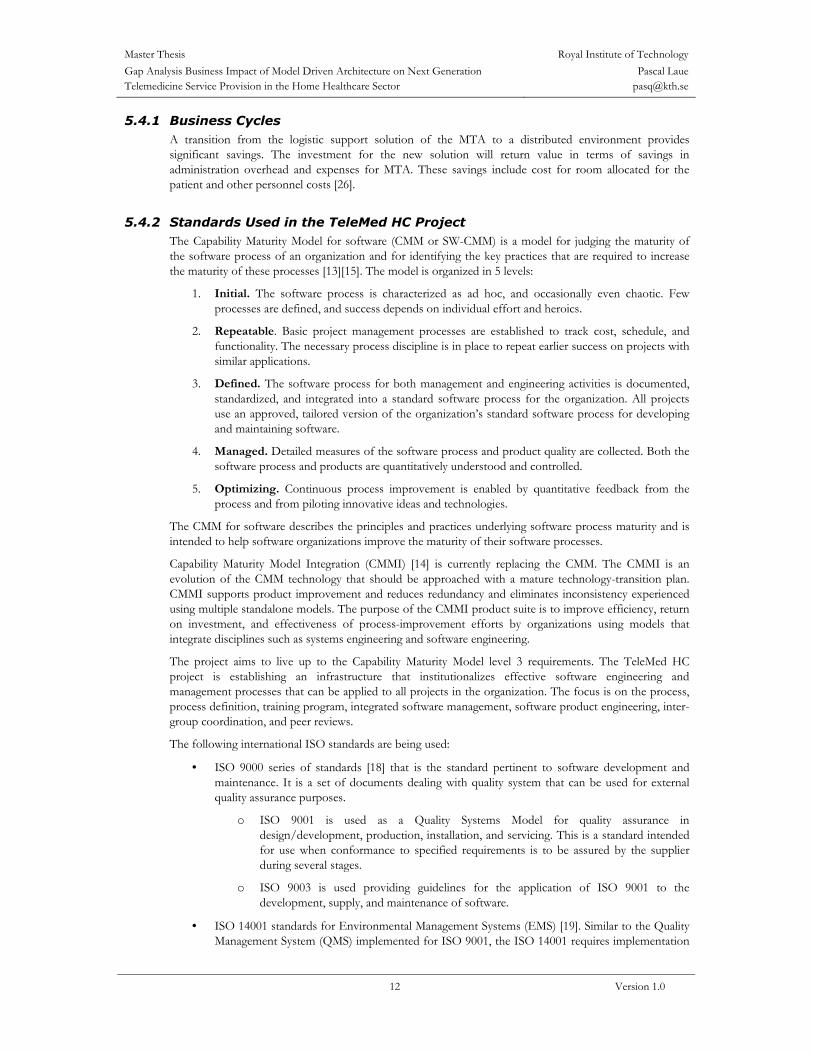
5.4.2 Standards Used in the TeleMed HC Project The Capability Maturity Model for software (CMM or SW-CMM) is a model for judging the maturity of the software process of an organization and for identifying the key practices that are required to increase the maturity of these processes [13][15]. The model is organized in 5 levels:
1. Initial. The software process is characterized as ad hoc, and occasionally even chaotic. Few processes are defined, and success depends on individual effort and heroics.
2. Repeatable. Basic project management processes are established to track cost, schedule, and functionality. The necessary process discipline is in place to repeat earlier success on projects with similar applications.
3. Defined. The software process for both management and engineering activities is documented, standardized, and integrated into a standard software process for the organization. All projects use an approved, tailored version of the organization’s standard software process for developing and maintaining software.
4. Managed. Detailed measures of the software process and product quality are collected. Both the software process and products are quantitatively understood and controlled.
5. Optimizing. Continuous process improvement is enabled by quantitative feedback from the process and from piloting innovative ideas and technologies.
The CMM for software describes the principles and practices underlying software process maturity and is intended to help software organizations improve the maturity of their software processes.
Capability Maturity Model Integration (CMMI) [14] is currently replacing the CMM. The CMMI is an evolution of the CMM technology that should be approached with a mature technology-transition plan. CMMI supports product improvement and reduces redundancy and eliminates inconsistency experienced using multiple standalone models. The purpose of the CMMI product suite is to improve efficiency, return on investment, and effectiveness of process-improvement efforts by organizations using models that integrate disciplines such as systems engineering and software engineering.
The project aims to live up to the Capability Maturity Model level 3 requirements. The TeleMed HC project is establishing an infrastructure that institutionalizes effective software engineering and management processes that can be applied to all projects in the organization. The focus is on the process, process definition, training program, integrated software management, software product engineering, inter-group coordination, and peer reviews.
The following international ISO standards are being used:
• ISO 9000 series of standards [18] that is the standard pertinent to software development and maintenance. It is a set of documents dealing with quality system that can be used for external quality assurance purposes.
o ISO 9001 is used as a Quality Systems Model for quality assurance in design/development, production, installation, and servicing. This is a standard intended for use when conformance to specified requirements is to be assured by the supplier during several stages.
o ISO 9003 is used providing guidelines for the application of ISO 9001 to the development, supply, and maintenance of software.
• ISO 14001 standards for Environmental Management Systems (EMS) [19]. Similar to the Quality Management System (QMS) implemented for ISO 9001, the ISO 14001 requires implementation

Master Thesis Royal Institute of TechnologyGap Analysis Business Impact of Model Driven Architecture on Next Generation Telemedicine Service Provision in the Home Healthcare Sector
Pascal Laue [email protected]
13 Version 1.0
of an Environmental Management System (EMS) in accordance with defined internationally recognized standards (as set forth in the ISO 14001 specification).
• ISO/IEC 17799:2000 addresses topics in terms of policies and general good practices [20]. The document specifically identifies itself as “a starting point for developing organization specific guidance”. It states that not all of the guidance and controls it contains may be applicable and that additional controls not contained may be required. It is not intended to give definitive details or “how to’s”.
It is not the purpose of this paper to introduce and describe the various methodologies available in the software development world. However, the Spiral model used in the pilot stage of the project will be described shortly. In order to achieve certain goals and expectations and a successful architectural framework, one needs to have a well-defined methodology process behind it.
Spiral development is a software development approach that is used for evaluation of risks so that the best suitable choice can be made for every development activity. The spiral model can be used for a more cost-effective incremental commitment of funds. Spiral development is a family of software development processes characterized by repeated iteration in every development process such as design, construction, and implementation. These iterations facilitate an effective risk reduction and management in the project.
The spiral model is a risk-driven process model generator. This model guides multi-stakeholders to do concurrent engineering in a software intensive project such as TeleMed HC. It has two main distinguishing features. One is a cyclic approach for incrementally growing a system’s degree of definition and implementation while decreasing its degree of risk. The other is a set of anchor point milestones for ensuring stakeholder commitment to feasible and mutually satisfactory system solutions. Risks in this project are those situations or possible events that can cause it to fail to meet its goals. They range in impact from trivial to fatal and in likelihood from certain to improbable. A risk management plan enumerates the risks and prioritizes them in degree of importance, as measured by a combination of the impact and likelihood of each. For each one, the plan also states a mitigation strategy to deal with the risk. For instance, the risk that technology is unready may be mitigated by an appropriate prototype implementation in an early spiral cycle. An overview of the spiral model is depicted in Appendix B: The Spiral Model.
Using Agile Modeling (AM) enabled the team to model and document the system effectively in a balanced way without slowing down the TeleMed HC project. The project team used the techniques of AM to improve and simplify the modeling efforts where the team did not take a pure agile approach.
6. Showcase: The TeleMed HC Project Having described the theoretical value and use of vertical and horizontal gap analyses, it remains to be seen how they are applied in a real-world project. The TeleMed HC project was used as a showcase to see the impact of using MDA, how a vertical GA was updated to fit a new system specification, and how horizontal gap analyses were used to support the decision process selecting an implementation approach. Last but not least, it was used to study the implications of using gap analyses with respect to the long-term strategies and visions for the system.
6.1 The Impact of Using MDA – A Comparative Study The work performed in the TeleMed HC Project so far has been part of three phases:
• Phase 1: Theoretical Pre-Study
• Phase 2: Proof-of-Concept Prototype
• Phase 3: Pilot System
During phase 2, MDA was not used, whereas in phase 3 it was. In order to see the impact of using MDA, these two phases will be compared. To get a fair picture of the comparison of the return on investment in

Master Thesis Royal Institute of TechnologyGap Analysis Business Impact of Model Driven Architecture on Next Generation Telemedicine Service Provision in the Home Healthcare Sector
Pascal Laue [email protected]
14 Version 1.0
these phases, the reader should keep in mind that using MDA might result in both tangible and intangible effects. An example for tangible effects would be monetary costs, examples for intangible ones improvements in quality resulting in higher security and a lower maintenance burden, or the development of standard procedures.
The baselines, goals, and outcomes for the two phases are shown in Table 6-1 below:
Phase Baseline Goal Outcome 2 6 KTH-students
1 industrial mentor Build a prototype Non-production proof of
concept 3 3 students
2 industrial mentors Build a production prototype/pilot system
Production pilot system
Table 6-1 Baselines, Goals, and Outcomes of Phases 2 and 3
In the beginning of phase 2, the project team organized itself by nominating a project manager and setting up a meeting schedule for internal meetings, meetings with their coach from KTH, and meetings with the stakeholders at HS. Every project team members was assigned responsibility for a part of the work [4], and templates for the project documents and meeting protocols were created, assuring a coherent look. For the development of the prototype, a spiral development model was adopted [3]. And still: about 5 months of intensive work later, only a minimalist, non-production proof-of-concept prototype had been developed; what had gone wrong?
Having no previous experience in building large enterprise systems, the project team focused on the implementation of the desired functionality. Without a detailed architecture and detailed end-to-end use cases allowing to estimate the complexity and time-consumption of the different implementation tasks, those estimations were very optimistic. As the system proved to be more complex than estimated, the project team tried to build the easily implemented parts first, counting on being able to solve the difficulties at a later point in time. This led to an attempt to build all the components of the system from scratch, building a standalone, monolithic system. This approach, however, proved to be impossible to realize, as the team lacked the expertise and time to build such a solution in a secure and scalable way, not to speak of providing good maintainability. Instead, under the lead of an industrial mentor, the project team had to change the architectural approach completely to a platform-based one, using COTS products for the message delivery from the client application to the server. Even though this work finally resulted in a prototype able to demonstrate the possibility of downloading data from a biomedical device (BMD) and sending it to a database, it was not designed and programmed well enough to derive a production system from it; most parts needed to be reworked completely.
Starting out with the third phase, 3 of the original 6 students committed themselves to developing a production pilot system that could be tested with real patients. This time, however, the team had an industrial mentor right from the start and used a different approach to system development. A detailed architecture was developed, showing dependencies between different parts of the system. Essential use cases, describing the end-to-end functionality, were developed based on the customer requirements. From the essential use cases, the software components to implement could be identified. Together with the architecture, these allowed to break down the work into tasks at a sufficiently granular level, providing time measurement in the order of half-day chunks. This allowed prioritizing the work in order of importance and to analyze which components could be re-used from the proof-of-concept prototype, which could be bought as COTS, and which finally needed to be built. Working this way also allowed identifying risks much earlier than before, allowing for a more proactive risk control. Another way of eliminating risk was to use or develop standard procedures and methodologies. The goal was to be able to document all work done in a way that would make it easy to communicate with the stakeholders, to coordinate the work within the team, and to make it possible to rebuild exactly the same development environment over and over again, eliminating undocumented dependencies.
The first step was to set up a development environment. This process was fully documented [28][25] which allowed to cut down the time needed for a complete set-up from several weeks the first time it was done to only about 12 hours [28] – this included installation of the operating system, database server, application
Master Thesis Royal Institute of TechnologyGap Analysis Business Impact of Model Driven Architecture on Next Generation Telemedicine Service Provision in the Home Healthcare Sector
Pascal Laue [email protected]
15 Version 1.0
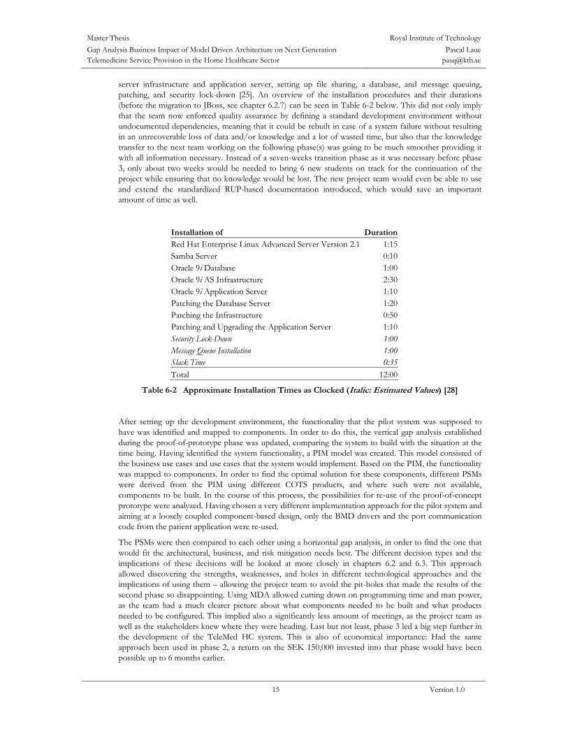
server infrastructure and application server, setting up file sharing, a database, and message queuing, patching, and security lock-down [25]. An overview of the installation procedures and their durations (before the migration to JBoss, see chapter 6.2.7) can be seen in Table 6-2 below. This did not only imply that the team now enforced quality assurance by defining a standard development environment without undocumented dependencies, meaning that it could be rebuilt in case of a system failure without resulting in an unrecoverable loss of data and/or knowledge and a lot of wasted time, but also that the knowledge transfer to the next team working on the following phase(s) was going to be much smoother providing it with all information necessary. Instead of a seven-weeks transition phase as it was necessary before phase 3, only about two weeks would be needed to bring 6 new students on track for the continuation of the project while ensuring that no knowledge would be lost. The new project team would even be able to use and extend the standardized RUP-based documentation introduced, which would save an important amount of time as well.
Installation of DurationRed Hat Enterprise Linux Advanced Server Version 2.1 1:15Samba Server 0:10Oracle 9i Database 1:00Oracle 9i AS Infrastructure 2:30Oracle 9i Application Server 1:10Patching the Database Server 1:20Patching the Infrastructure 0:50Patching and Upgrading the Application Server 1:10Security Lock-Down 1:00Message Queue Installation 1:00Slack Time 0:35Total 12:00
Table 6-2 Approximate Installation Times as Clocked (Italic: Estimated Values) [28]
After setting up the development environment, the functionality that the pilot system was supposed to have was identified and mapped to components. In order to do this, the vertical gap analysis established during the proof-of-prototype phase was updated, comparing the system to build with the situation at the time being. Having identified the system functionality, a PIM model was created. This model consisted of the business use cases and use cases that the system would implement. Based on the PIM, the functionality was mapped to components. In order to find the optimal solution for these components, different PSMs were derived from the PIM using different COTS products, and where such were not available, components to be built. In the course of this process, the possibilities for re-use of the proof-of-concept prototype were analyzed. Having chosen a very different implementation approach for the pilot system and aiming at a loosely coupled component-based design, only the BMD drivers and the port communication code from the patient application were re-used.
The PSMs were then compared to each other using a horizontal gap analysis, in order to find the one that would fit the architectural, business, and risk mitigation needs best. The different decision types and the implications of these decisions will be looked at more closely in chapters 6.2 and 6.3. This approach allowed discovering the strengths, weaknesses, and holes in different technological approaches and the implications of using them – allowing the project team to avoid the pit-holes that made the results of the second phase so disappointing. Using MDA allowed cutting down on programming time and man power, as the team had a much clearer picture about what components needed to be built and what products needed to be configured. This implied also a significantly less amount of meetings, as the project team as well as the stakeholders knew where they were heading. Last but not least, phase 3 led a big step further in the development of the TeleMed HC system. This is also of economical importance: Had the same approach been used in phase 2, a return on the SEK 150,000 invested into that phase would have been possible up to 6 months earlier.
Master Thesis Royal Institute of TechnologyGap Analysis Business Impact of Model Driven Architecture on Next Generation Telemedicine Service Provision in the Home Healthcare Sector
Pascal Laue [email protected]
16 Version 1.0
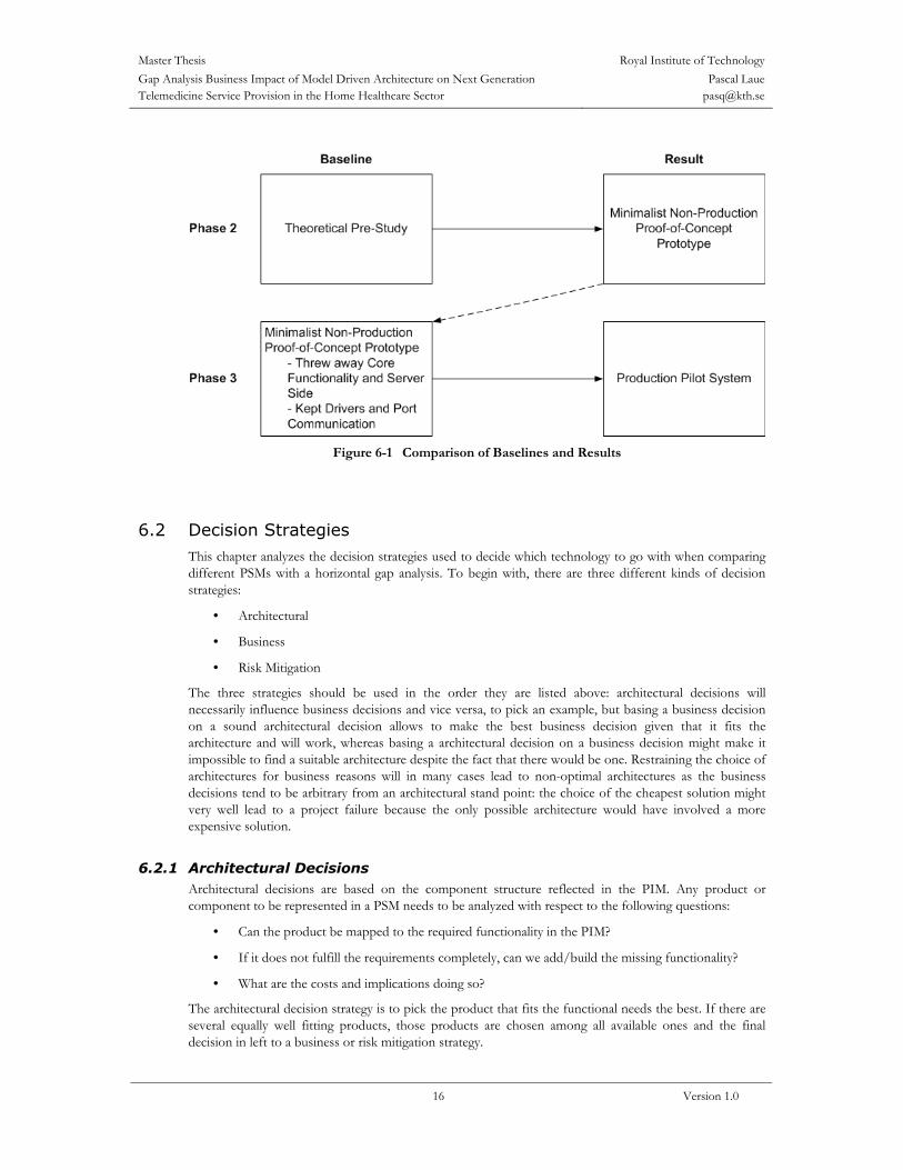
Figure 6-1 Comparison of Baselines and Results
6.2 Decision Strategies This chapter analyzes the decision strategies used to decide which technology to go with when comparing different PSMs with a horizontal gap analysis. To begin with, there are three different kinds of decision strategies:
• Architectural
• Business
• Risk Mitigation
The three strategies should be used in the order they are listed above: architectural decisions will necessarily influence business decisions and vice versa, to pick an example, but basing a business decision on a sound architectural decision allows to make the best business decision given that it fits the architecture and will work, whereas basing a architectural decision on a business decision might make it impossible to find a suitable architecture despite the fact that there would be one. Restraining the choice of architectures for business reasons will in many cases lead to non-optimal architectures as the business decisions tend to be arbitrary from an architectural stand point: the choice of the cheapest solution might very well lead to a project failure because the only possible architecture would have involved a more expensive solution.
6.2.1 Architectural Decisions Architectural decisions are based on the component structure reflected in the PIM. Any product or component to be represented in a PSM needs to be analyzed with respect to the following questions:
• Can the product be mapped to the required functionality in the PIM?
• If it does not fulfill the requirements completely, can we add/build the missing functionality?
• What are the costs and implications doing so?
The architectural decision strategy is to pick the product that fits the functional needs the best. If there are several equally well fitting products, those products are chosen among all available ones and the final decision in left to a business or risk mitigation strategy.

Master Thesis Royal Institute of TechnologyGap Analysis Business Impact of Model Driven Architecture on Next Generation Telemedicine Service Provision in the Home Healthcare Sector
Pascal Laue [email protected]
17 Version 1.0
6.2.2 Business Decisions Business decisions are based on the total cost and the return on investment of a specific solution. Choosing between the different solutions that fulfill the architectural requirements, the one with the lowest costs in term of purchase, license, and maintenance costs will typically be chosen. A typical business strategy is to choose an already licensed COTS product, as this will minimize the purchase and license costs, as well as the need to train staff, and future maintenance efforts. Business decisions could also involve long-term industry trends, for example the choice of a solution that is evolving to an industry standard in place for a cheaper one. The most common business decision strategy is the ‘re-use before buy before build’-strategy.
6.2.3 Risk Mitigation Risk mitigation strategies involve the choice of a technology that is well known to the developers and the users, to replace an earlier chosen technology with one that supports the intended solution in a better way, and so on, in order to minimize the risk of a delay or project failure. Risk mitigation often involves back-up solutions in case the first choice fails to provide the necessary functionality.
Figure 6-2 TMHC Pilot System Conceptual Model
The four examples below show the decision process for some of the COTS products used to provide the functionality specified by the PIM.

Master Thesis Royal Institute of TechnologyGap Analysis Business Impact of Model Driven Architecture on Next Generation Telemedicine Service Provision in the Home Healthcare Sector
Pascal Laue [email protected]
18 Version 1.0
6.2.4 Example 1 – Database: Architectural and Business Decision Since the TeleMed HC platform was designed to be super-scalable, the database to be chosen needed to have high standards with respect to
• Throughput
• Reliability
• Failover
• Scalability and Robustness
• Support for Store Procedures
The COTS products fulfilling these architectural requirements were the following ones [42]:
• IBM DB2
• Oracle 9i
• Postgress
• MySQL (newest version)
From these candidates, Oracle 9i was selected. The reason was that HS already had a license for Oracle products including the 9i database server and application server products. This reduced the license costs to a minimum (no additional costs) as well as the staff training and maintenance costs: no staff needed to be trained, and the staff in charge for the maintenance of the existing Oracle databases would be able to maintain the new ones as well.
In this case, a combination of architectural and business requirements was applied to find the optimal COTS product for the repository functionality. First, the choice was narrowed by selecting only those products that fullfilled the architectural requirements. From these, the one with the lowest cost in terms of software acquisition, license, and maintenace, was selected.
6.2.5 Example 2 – Server Operating System: Business Decision Having selected an Oracle 9i database server, the operating system had to fulfill the requirements imposed by this choice. HS decided to use a Linux operating system in order to minimize license costs. The Linux operating systems certified for the use together with the Oracle 9i database server were the following ones [35]:
• Red Hat Enterprise Linux Advanced Server 2.1
• SUSE Linux Enterprise Server 7
HS was already using Red Hat Linux and had staff trained to maintain it. Furthermore, it seemed that the development in the industry was moving towards using Red Hat. Considering these two reasons, Red Hat seemed to be a clearly better choice than SUSE from a business view point, because it reduced maintenance costs as no new staff needed to be trained. There was also a certain expectation to see an increasing amount of systems built on Red Hat in the future, assuring a continued development and support of the operating system.
The selection of Red Hat was a pure business decision, the choice being constrained by the adoption of an Oracle database server. Even here, the minimization of short- and long-term costs were the main reasons for the choice of Red Hat.
Master Thesis Royal Institute of TechnologyGap Analysis Business Impact of Model Driven Architecture on Next Generation Telemedicine Service Provision in the Home Healthcare Sector
Pascal Laue [email protected]
19 Version 1.0
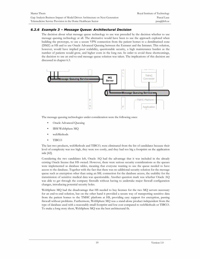
6.2.6 Example 3 – Message Queue: Architectural Decision The decision about what message queue technology to use was preceded by the decision whether to use message queuing technology at all. The alternative would have been to use the approach explored when building the prototype, to use a secure VPN connection from the patient homes to a demilitarized zone (DMZ) at HS and to use Oracle Advanced Queuing between the Extranet and the Intranet. This solution, however, would have implied poor scalability, questionable security, a high maintenance burden as the number of patients would grow, and higher costs in the long run. In order to avoid these shortcomings, the decision to use an end-to-end message queue solution was taken. The implications of this decision are discussed in chapter 6.3.
The message queuing technologies under consideration were the following ones:
• Oracle Advanced Queuing
• IBM WebSphere MQ
• webMethods
• TIBCO
The last two products, webMethods and TIBCO, were eliminated from the list of candidates because their level of complexity was too high, they were too costly, and they had too big a footprint on the application side [42].
Considering the two candidates left, Oracle AQ had the advantage that it was included in the already existing Oracle license that HS owned. However, there were serious security considerations as the queues were implemented as database tables, meaning that everyone wanting to use the queue needed to have access to the database. Together with the fact that there was no additional security solution for the message queue such as encryption other than using an SSL connection for the database access, the usability for the transmission of sensitive medical data was questionable. Another question mark was whether Oracle AQ was able to get through the company firewalls without having to undertake major firewall configuration changes, introducing potential security holes.
WebSphere MQ had the disadvantage that HS needed to buy licenses for the two MQ servers necessary for an end-to-end solution, but on the other hand it provided a secure way of transporting sensitive data from the patient homes to the TMHC platform at HS, providing easy support for encryption, passing firewall without problems. Furthermore, WebSphere MQ was a stand-alone product independent from the type of database used with a reasonably small footprint and low cost compared to webMethods or TIBCO. To make a long story short, WebSphere MQ was the best architectural fit.

Master Thesis Royal Institute of TechnologyGap Analysis Business Impact of Model Driven Architecture on Next Generation Telemedicine Service Provision in the Home Healthcare Sector
Pascal Laue [email protected]
20 Version 1.0
6.2.7 Example 4 – Application Server: Risk Mitigation Decision To begin with, Oracle 9iAS was selected as the application server for the same reasons as the Oracle 9i database server: HS already owned a license and had trained staff knowing to operate and maintain it.
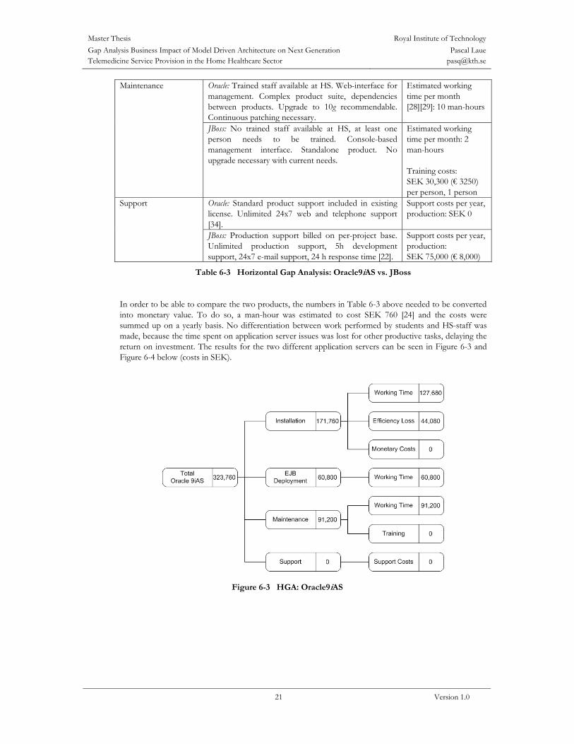
When it came to deploying the Java Beans handling the messages from the patient applications, though, problems arose when trying to deploy those Beans on the application server. The deployment procedure proved to be time consuming and non-intuitive, and even after having deployed the Beans, it took several minutes before they actually became operational. In addition to these inconveniences, the Beans became unreachable after performing an upgrade to the Oracle 9i application server, meaning that they had to be removed manually and re-deployed. Even after this upgrade, the deployment and especially the re-deployment procedures were time consuming and the beans did not get operational immediately. Even worse, despite many attempts, the beans just would not work the way they were expected to on the Oracle9iAS. As Oracle had moved to the new 10g platform and discontinued the development of the 9i platform, there was no fix to be expected to solve this problem [42]. The project team did not have much time left and decided to evaluate the use of a different application server. The popular open source application server JBoss seemed to be a good alternative to the Oracle 9iAS. JBoss seemed much easier to handle and when deploying beans, they became almost immediately operational. As both products fulfilled the functional requirements, it was interesting to compare them with respect to technical, economic, and maintenance aspects. Table 6-3 below shows a comparison between the two products partly from a rear-window perspective, analyzing the actual working time invested and costs and efficiency losses incurred, and partly from a front-window perspective, estimating the work needed and costs incurred down the road to maintain those products.
Issue Description Quantification Oracle: Oracle 9iAS is very difficult to install on Red Hat Linux. The operating system needs to be tuned; otherwise the installation will not succeed. Installation information is spread out over many documents. Installation documentation and support are included in existing license. Patching and upgrading is necessary after installation [28]. The complexity of the task leads to distraction of non-assigned project members, as they want to participate in the learning experience. This leads to decreased overall performance and efficiency of the project team.
Working time [29]: 168 man-hours Estimated efficiency loss: 20% per person, 2 persons, during 18 days [29] = 58 man-hours1 Direct monetary cost: SEK 0
Ease of an out-of-the-box installation (first-time installation)
JBoss: Easy to install on Red Hat Linux. No operation system tuning necessary. Installation information is available in a single document that needs to be purchased. No patching or upgrading necessary after installation.
Working time [43]: 80 man-hours Direct monetary cost [21]: SEK 75 (US $ 10) per person, 1 person
Oracle: Non-intuitive deployment procedure. Re-deployment slow, application server needs to be bounced. Problems with product upgrades. Java Beans did not work as expected.
Working time [43]: 80 man-hours
EJB deployment
JBoss: Intuitive and simple deployment procedure. Re-deployment very fast, no bouncing needed. The Java Beans worked fine.
Working time [43]: 8 man-hours
1 1 day = 8 man-hours. 0.2*2 persons*18 days*8 hours = 57.6 man-hours ≈ 58 man-hours
Master Thesis Royal Institute of TechnologyGap Analysis Business Impact of Model Driven Architecture on Next Generation Telemedicine Service Provision in the Home Healthcare Sector
Pascal Laue [email protected]
21 Version 1.0
Oracle: Trained staff available at HS. Web-interface for management. Complex product suite, dependencies between products. Upgrade to 10g recommendable. Continuous patching necessary.
Estimated working time per month [28][29]: 10 man-hours
Maintenance
JBoss: No trained staff available at HS, at least one person needs to be trained. Console-based management interface. Standalone product. No upgrade necessary with current needs.
Estimated working time per month: 2 man-hours Training costs: SEK 30,300 (€ 3250) per person, 1 person
Oracle: Standard product support included in existing license. Unlimited 24x7 web and telephone support [34].
Support costs per year, production: SEK 0
Support
JBoss: Production support billed on per-project base. Unlimited production support, 5h development support, 24x7 e-mail support, 24 h response time [22].
Support costs per year, production: SEK 75,000 (€ 8,000)
Table 6-3 Horizontal Gap Analysis: Oracle9iAS vs. JBoss
In order to be able to compare the two products, the numbers in Table 6-3 above needed to be converted into monetary value. To do so, a man-hour was estimated to cost SEK 760 [24] and the costs were summed up on a yearly basis. No differentiation between work performed by students and HS-staff was made, because the time spent on application server issues was lost for other productive tasks, delaying the return on investment. The results for the two different application servers can be seen in Figure 6-3 and Figure 6-4 below (costs in SEK).
Figure 6-3 HGA: Oracle9iAS

Master Thesis Royal Institute of TechnologyGap Analysis Business Impact of Model Driven Architecture on Next Generation Telemedicine Service Provision in the Home Healthcare Sector
Pascal Laue [email protected]
22 Version 1.0
Figure 6-4 HGA: JBoss
Looking back and knowing how things went, selecting the JBoss application server from the beginning would have saved a lot of money. However, not knowing about the installation and EJB deployment issues, the best decision seemed to choose Oracle9iAS. The decision to use a different application server than planned from the beginning was a risk mitigation decision, avoiding spending a lot of time on trying to fix a problem that might not have had any satisfying solution.
6.3 Implications Every decision that touches the questions of how a new system is going to be used, what should be built, and how it should be implemented, will have an impact on the success of the project. It is therefore very important to be able to take those decisions in an ordered way, trying to get as much and as relevant information as possible on the issues to decide about. The way MDA is structured suggests that for the best possible chance of success when building a new system, three levels of review are required:
• A business management review: This review decides on the workflows and business use cases to be included in the CIM. At this review, it is decided how the system is going to be used and what the requirements are for it to be useful. In order to be able to see the changes this new system introduces, a vertical gap analysis can be used. It should analyze the changes the new system will introduce to the company’s way of doing its everyday business and the economical impacts it might have.
• An architectural review: This review decides about what the architecture of the system will look like in terms of a PIM. At this review, the scope for the system to be built is set, defining what functionality will be provided. A vertical gap analysis should be used to analyze if the envisioned system is feasible and how the chosen architecture and scope will impact the company’s way of doing its business. It is also of interest to analyze the innovativeness of the system, providing an estimation of the future value of the system. If a vertical GA has been established for the business management review already, it should be refined and adapted to the selected architectural approach.
• An implementation approach review: This review decides to go with a certain implementation approach specified in a PSM. This is an important review, taking the project from the planning stage to the actual building stage. A horizontal gap analysis should be used to compare different implementation approaches to one another. The vertical gap analysis established for the architectural review needs to be updated for
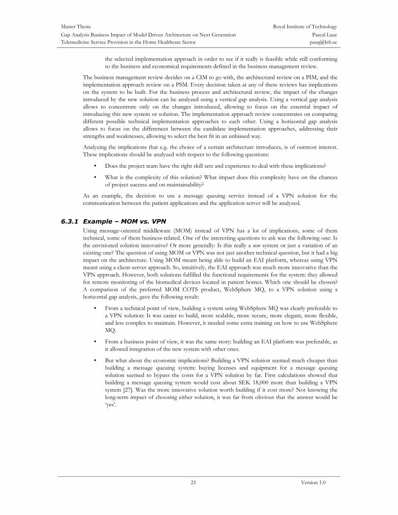
Master Thesis Royal Institute of TechnologyGap Analysis Business Impact of Model Driven Architecture on Next Generation Telemedicine Service Provision in the Home Healthcare Sector
Pascal Laue [email protected]
23 Version 1.0
the selected implementation approach in order to see if it really is feasible while still conforming to the business and economical requirements defined in the business management review.
The business management review decides on a CIM to go with, the architectural review on a PIM, and the implementation approach review on a PSM. Every decision taken at any of these reviews has implications on the system to be built. For the business process and architectural review, the impact of the changes introduced by the new solution can be analyzed using a vertical gap analysis. Using a vertical gap analysis allows to concentrate only on the changes introduced, allowing to focus on the essential impact of introducing this new system or solution. The implementation approach review concentrates on comparing different possible technical implementation approaches to each other. Using a horizontal gap analysis allows to focus on the differences between the candidate implementation approaches, addressing their strengths and weaknesses, allowing to select the best fit in an unbiased way.
Analyzing the implications that e.g. the choice of a certain architecture introduces, is of outmost interest. These implications should be analyzed with respect to the following questions:
• Does the project team have the right skill sets and experience to deal with these implications?
• What is the complexity of this solution? What impact does this complexity have on the chances of project success and on maintainability?
As an example, the decision to use a message queuing service instead of a VPN solution for the communication between the patient applications and the application server will be analyzed.
6.3.1 Example – MOM vs. VPN Using message-oriented middleware (MOM) instead of VPN has a lot of implications, some of them technical, some of them business-related. One of the interesting questions to ask was the following one: Is the envisioned solution innovative? Or more generally: Is this really a new system or just a variation of an existing one? The question of using MOM or VPN was not just another technical question, but it had a big impact on the architecture. Using MOM meant being able to build an EAI platform, whereas using VPN meant using a client-server approach. So, intuitively, the EAI approach was much more innovative than the VPN approach. However, both solutions fulfilled the functional requirements for the system: they allowed for remote monitoring of the biomedical devices located in patient homes. Which one should be chosen? A comparison of the preferred MOM COTS product, WebSphere MQ, to a VPN solution using a horizontal gap analysis, gave the following result:
• From a technical point of view, building a system using WebSphere MQ was clearly preferable to a VPN solution: It was easier to build, more scalable, more secure, more elegant, more flexible, and less complex to maintain. However, it needed some extra training on how to use WebSphere MQ.
• From a business point of view, it was the same story: building an EAI platform was preferable, as it allowed integration of the new system with other ones.
• But what about the economic implications? Building a VPN solution seemed much cheaper than building a message queuing system: buying licenses and equipment for a message queuing solution seemed to bypass the costs for a VPN solution by far. First calculations showed that building a message queuing system would cost about SEK 18,000 more than building a VPN system [27]. Was the more innovative solution worth building if it cost more? Not knowing the long-term impact of choosing either solution, it was far from obvious that the answer would be ‘yes’.

Master Thesis Royal Institute of TechnologyGap Analysis Business Impact of Model Driven Architecture on Next Generation Telemedicine Service Provision in the Home Healthcare Sector
Pascal Laue [email protected]
24 Version 1.0
Figure 6-5 The Architecture of the VPN Approach
However, the above comparison focused only on building the pilot system. What would happen when it actually went into production? When hundreds or thousands of applications would need to connect to the server/platform? How would the costs be affected by maintenance and/or training? What would the prospects for generating revenue for the system be? To get answers to these questions, the long-term implications of using either of these two approaches needed to be compared. In order to do so, the vertical gap analysis was updated for those two solutions, allowing to compare their implications on the long-term strategy for the system. This comparison led to, among others, the conclusions that using MOM meant that:
• It would be easy to build new applications or to integrate existing ones, using the platform
• The system would be much easier to maintain, which meant that lower maintenance cost were incurred
• The knowledge transfer from the builders to the maintainers and users of the system would be faster and easier, among other reasons because the licenses for the used COTS products included customer support from the vendors
• Different business models could be used in order to generate a revenue stream from this new system (as described in chapter 2.2.3), implying an early return on investment
• The total cost of ownership would be decreased
• The future value of the system would be much higher as it would be reusable and easy to upgrade
A new calculation on the costs for both solutions, taking into account the maintenance of the system, resulted in a different economical picture: As the VPN solution would require an extra server for security reasons and would render the system more complex to maintain, costs for this solution would actually become much higher than for the MOM solution [27].
7. Conclusions
7.1 Conclusion The examples in chapter 6 show that vertical and horizontal gap analyses, applied within the framework of MDA, are a powerful decision-support and risk-mitigation tool. Not only do they allow removing bias
Master Thesis Royal Institute of TechnologyGap Analysis Business Impact of Model Driven Architecture on Next Generation Telemedicine Service Provision in the Home Healthcare Sector
Pascal Laue [email protected]
25 Version 1.0
from the decision base, they also simplify the decision taking process by focusing on the differences between new and old systems or different implementations, respectively. Doing so puts the focus on their strengths and weaknesses, filtering out common capabilities. Knowing about the weaknesses of a particular solution allows planning for their elimination, decreasing project risk.
In order to provide a valid horizontal gap analysis of high quality, however, a good level of knowledge of the different COTS products and/or implementation approaches is necessary; a gap analysis is only as good as the information it relies on. This implies that the person elaborating such a gap analysis needs to either invest a rather large amount of time in investigating the different products/implementation approaches or needs to have access to one or several experts knowing those products. The same is also valid for vertical gap analyses; good knowledge about the business of the company in question and its workflows is necessary for the elaboration of a valid vertical gap analysis of high quality.
Model Driven Architecture provides a sound approach to system development by providing models at different levels, supporting a decision taking process at several stages and points in time. Vertical and horizontal gap analyses support this approach by providing the required information to base a decision on at the different project reviews. They also allow taking into consideration the long-time implications a decision might have. These may suggest adopting a different solution than the conclusion after consideration of only the short-time goals would. The solution of choice must have a solid business justification. Risk mitigation and the ‘re-use before buy before build’ principle are main driving factors for this decision process. One of the main advantages gained from the use of MDA in this project was probably that it made it easier to act proactive; it allowed identifying the different puzzle bits the system consisted of and estimating their complexity.
The use of RUP as a base for AM was a rather good choice, even though the level of documentation coming with RUP is enormous and needed to be stripped down very much to fit a small development team of only 3 people. In addition to that, having to establish all the procedures and documents required for the first time, having hardly any guidelines and example documents to go after, required a lot of energy and effort. Even though we profited by the structure provided by RUP, those who will profit most of this work are probably the new KTH students who have taken over after us. For the software design, the use of a code generation tool such as Rational Rose is highly recommendable, as it speeds up the development and programming quite a lot. Had the project team had access to such a tool, the time saved during design and implementation had allowed for a more thought-through and thorough software design.
When it comes to the use of standards, it is almost impossible for me to judge if the project has met their requirements in this phase. The establishment of a standardized, RUP-based documentation and the use of Model Driven Architecture should assure its compliance with level 2 (repeatable) of the CMM, but compliance with level 3 (defined) the project team aimed for, is questionable. It is possible, though, that the next group of students will be able to establish full level 3 compliance at least within the TeleMed HC project. As far as the other standards are concerned, I have not seen any follow up and cannot judge whether we managed to comply with them or not and to which extent. What can be said with certainty, though, is that the result of the pilot phase was of much higher quality than the one of the proof-of-concept phase.
Introducing a new IT system into a healthcare organization proved to be more complicated than expected. The low level of protection of the hospital’s intranet did not allow to rely on it being secured: only one single firewall is used, making it not too hard to break into the system in case of a security breach in this particular model. As it seems, IT security does not have a very high priority at HS as no big harm has been done to any system, yet, making it hard for the security responsible to persuade the management of the need for improvements (and more funding). The introduction of a new IT system like the TeleMed HC platform into a healthcare environment puts high demands on security, as sensitive patient data is transferred from an uncontrolled environment — the patient home — to the hospital’s intranet, potentially opening it to intruders. This problem could be solved in an elegant way using WebSphere MQ, providing encryption — securing the patient data on its travel through the Internet — and session-based message handling, discarding messages that are not expected or that do not conform to the expected message format.

Master Thesis Royal Institute of TechnologyGap Analysis Business Impact of Model Driven Architecture on Next Generation Telemedicine Service Provision in the Home Healthcare Sector
Pascal Laue [email protected]
26 Version 1.0
7.2 Future Work As high levels of knowledge are necessary for elaborating good gap analyses, an automated decision support tool would be of great help. Such a tool could establish both vertical and horizontal gap analyses based on information collected from earlier projects, information about the structure of the company and its workflows, and the features of available COTS products.
In order to be able to build such a tool, patterns driving the choice of such solutions and products need to be discovered and documented. Such patterns would also be helpful without an automated tool, providing guidance and best practices to system development and architecture professionals.
A different area of interest for future work is the evaluation of horizontal gap analyses at the CIM level, providing a comparison for different business process models. A possible application for such a study would be process re-engineering in response to the technical changes introduced into the organization by the TeleMed HC system.
7.3 Lessons Learned
7.3.1 CSD Project The development team’s experiences from the proof-of-concept phase of the TeleMed HC project can be summarized as follows:
• Rotating management (meaning that every team member was acting as the project manager for a period of 3 weeks) led to inefficiency in the work. This was due to inexperience and a lack of project management skills.
• Unclear roles in the team lead to confusion and misunderstandings.
• Too wide a scope and undefined goals caused focusing on unnecessary tasks.
• The implementation was prioritized over focus on architecture and general functionality. This led to poor reusability and quality of design.
• The development team lacked experience of larger projects, which caused poor communication; deadlines were not always kept. The management team should have provided more structure and aid to solve this problem.
• Generally, the usage of a spiral model methodology created a solid development model and aided the development process a lot.
• A large amount of freedom and responsibility for the development team led to creativity, innovation and personal development. But it also reduced the efficiency of the team considerably.
7.3.2 Pilot Phase During the first half of the pilot phase, a large portion of the project team’s efforts was spent on documentation. The focus of the documentation was primary on infrastructure installation, configuration, and security, and some general RUP documents. The project team is fully aware of the importance of these documents, but spending a huge amount of time on this kind of artifacts in the beginning of the phase led to that the documentation suffered in the latter part of the project.
Entering the pilot phase, the project team had a vague vision of what it wanted to achieve. But since it did not have any clear goals or sub-goals that where defined and shared among the project participants, confusion and misunderstandings arose. Unclear roles and responsibilities at both the student team and management level added to the confusion but also gave the team room for creativity and innovation.
Although the unclear goals and roles where influencing the project negatively, they did not have any greater impact on this phase. The quality of the work was not affected, but perhaps the end result did not reach its full potential.

Master Thesis Royal Institute of TechnologyGap Analysis Business Impact of Model Driven Architecture on Next Generation Telemedicine Service Provision in the Home Healthcare Sector
Pascal Laue [email protected]
27 Version 1.0
7.3.3 Expectations and Outcomes
Expectation Outcome Reasons Development of two applications, a patient application (PA) and an application for MTA
Only the PA was built • High workload during requirement analysis for PA
• Work overload and lack of detailed time and activity plan
Test of the system in real-world environment with patients
System only tested within the Intranet at HS
• Lack of time • Security policy did not
allow to execute test with the available hardware
Many problems Rather few problems • Training • Better awareness of risks • Fewer mistakes during
analysis and design phases • Use of MDA and gap
analyses Professional Continuation of the Project
Continuation as a new CSD Project
• Lower Cost
7.3.4 MDA, RUP, and AM Generally speaking, it took quite some time to get acquainted with all the methodologies to be used. As it is hard to grasp all the concepts at once and within a short time, it takes good leadership within the project group to achieve effective work.
MDA The advantages of using MDA were mainly the following ones:
• The separation of functionality from the implementation approach made it easier to discover the difficult problems and to find a solution for them early in the project
• It provided flexibility, allowing exchanging whole components without affecting the rest of the system
• Requirements become traceable, all the way from the specification to the implementation
The main disadvantage the project team was confronted with was that there are a large number of UML models that may be used; their establishment can take a lot of time. Being able to select the necessary models demands routine.
MDA being a framework has the advantage that it provides a fairly simple ‘recipe’ on how to do things, but on the other hand, it does not give very much practical support.
RUP The big advantage using RUP was that it provided a structure the project team could rely on; however, its use also implied a large amount of documentation, which needed to be filtered in order to retrieve the documents important for this rather small project. Also, the project team being so small, it was not possible to distribute the roles that RUP defines in a satisfactory way, leading to an unclear distribution of roles and responsibilities within the project team.
RUP/AM The spiral development approach of RUP combined with the flexibility provided by AM made it easier to adapt to changing requirements.

Master Thesis Royal Institute of TechnologyGap Analysis Business Impact of Model Driven Architecture on Next Generation Telemedicine Service Provision in the Home Healthcare Sector
Pascal Laue [email protected]
28 Version 1.0
8. Acronyms
A AM Agile Modeling AQ Advanced Queue B C CIM Computation Independent Model CMM Capability Maturity Model CMMI Capability Maturity Model Integration COTS Commercial Off-The-Shelf CSD Communication Systems Design D DIMIS Department of Innovation and Medical Information Systems DMZ De-militarized Zone E EAI Enterprise Application Integration ECG Electrocardiogram EJB Enterprise Java Beans EMS Environmental Management System F G GA Gap Analysis H HGA Horizontal Gap Analysis HS Huddinge University Hospital
Huddinge Universitetssjukhus I IDL Interface Definition Language IEC International Engineering Consortium ISO International Organization for Standardization J J2EE Java 2 Platform, Enterprise Edition K KTH Royal Institute of Technology
Kungl Tekniska Högskolan KS Karolinska Hospital
Karolinska Sjukhuset KUS Karolinska University Hospital
Karolinska Universitetssjukhuset KUS HS Karolinska University Hospital, Huddinge (former Huddinge
University Hospital) KUS KS Karolinska University Hospital, Solna (former Karolinska Hospital) L M MDA Model Driven Architecture MOM Message-Oriented Middleware MTA Biomedical Engineering Department
Medicintekniska avdelningen N O OMG Object Management Group OOAD Object-Oriented Analysis and Design P PC Personal Computer

Master Thesis Royal Institute of TechnologyGap Analysis Business Impact of Model Driven Architecture on Next Generation Telemedicine Service Provision in the Home Healthcare Sector
Pascal Laue [email protected]
29 Version 1.0
PIM Platform Independent Model PSM Platform Specific Model Q QMS Quality Management System R RAM Random Access Memory ROI Return on Investment RUP Rational Unified Process S SEK Swedish Krona SW-CMM Capability Maturity Model for Software T TCO Total Cost of Ownership TeleMed HC Telemedicine Home Care TMHC See ‘TeleMed HC’ U UML Unified Modeling Language V VGA Vertical Gap Analysis VPN Virtual Private Network W X Y Z
9. References
9.1 Printed and Electronic Sources [1] Alander, A. (2003). TeleMed HC – Software Development Plan. Huddinge University Hospital
[2] Alander, A., Kopparhed, D., Larsson, A., Laue, P., Merdi, P., Rahman, S. (2003): Next Generation Telemedicine Service Provision in the Home Healthcare Sector: Final Report. Stockholm: KTH
[3] Alander, A., Kopparhed, D., Larsson, A., Laue P., Merdi, P., Rahman, S. (2003). Next Generation Telemedicine Service Provision in the Home Healthcare Sector: Lessons Learned. Stockholm: KTH
[4] Alander, A., Kopparhed, D., Larsson, A., Laue P., Merdi, P., Rahman, S. (2003). Next Generation Telemedicine Service Provision in the Home Healthcare Sector: Project Plan. Stockholm: KTH
[5] Alhir, Sinan Si (2002). Guide to Applying the UML. New York: Springer-Verlag New York Inc. ISBN: 0-387-95209-8
[6] Ambler, Scott W. (2002). Agile Modeling. New York: John Wiley & Sons, Inc. ISBN: 0-471-20282-7
[7] Ambler, Scott W. (2003). The Elements of UML Style. Cambridge: Cambridge University Press. ISBN: 0-521-52547-0
[8] Auldenfire Sweden AB (2003). Auldenfire Agile Methodology. URL: http://www.auldenfire.se/ase/method.shtml
[9] Baldwin, Donald J. II (2003). Enterprise Software Architecture: Model Driven Architecture – An Auldenfire AtelierSM Approach.
[10] Bunting, R. (2000). Bridging the framework modeling and implementation gap. IBM Systems Journal, vol. 39, no. 2, 2000, p. 267-284

Master Thesis Royal Institute of TechnologyGap Analysis Business Impact of Model Driven Architecture on Next Generation Telemedicine Service Provision in the Home Healthcare Sector
Pascal Laue [email protected]
30 Version 1.0
[11] Bye, Peter (2000). Architectures: Blueprints for Integration. A Tutorial White Paper. Unisys.
[12] Bye, Peter (2000). Message Queuing Middleware. White Paper. Unisys.
[13] Carnegie Mellon Software Engineering Institute (2003). Capability Maturity Model (SW-CMM) for Software. URL: http://www.sei.cmu.edu/cmm/cmm.sum.html
[14] Carnegie Mellon Software Engineering Institute (2004). CMMI main page. URL: http://www.sei.cmu.edu/cmmi/
[15] Carnegie Mellon University Software Engineering Institute (1995). The Capability Maturity Model: Guidelines for Improving the Software Process. Addison-Wesley. ISBN: 0-201-54664-7
[16] Fowler, M., Scott, K. (2002). UML Distilled: Second Edition. A Brief Guide to the Standard Object Modeling Language. Addison Wesley Longman, Inc. ISBN: 0-201-65783-X
[17] Gupta, D., Iborra, J., Nilsson, A., Sadat, A., Santos, L., Zheng, P. (2004). TeleMed HC: Project Plan URL: http://csd.ssvl.kth.se/~csd2004-team10/documents/ProjectPlan_1.0_040206.pdf
[18] International Organization for Standardization (ISO). ISO 9000. URL: http://www.iso.org/iso/en/iso9000-14000/iso9000/iso9000index.html
[19] International Organization for Standardization (ISO). ISO 14000. URL: http://www.iso.org/iso/en/iso9000-14000/iso14000/iso14000index.html
[20] International Organization for Standardization (ISO). ISO/IEC 17799:2000. URL: http://www.iso.org/iso/en/CatalogueDetailPage.CatalogueDetail?CSNUMBER=33441&ICS1=35&ICS2=40&ICS3=
[21] JBoss (2004). Quality Documentation from the Source. URL: http://jboss.org/docs/index
[22] JBoss Group (2004). Production Support. URL: http://www.jboss.com/index.html?module=html&op=userdisplay&id=services/production
[23] JBossGroup (2004). JBoss Group Training. URL: http://www.jboss.com/index.html?module=html&op=userdisplay&id=services/training/index
[24] Kopparhed, Dan. Rahman, Shahidur (2003): Next Generation Telemedicine Service Provision in the Home Healthcare Sector: Business Analysis. Stockholm: KTH
[25] Larsson, A. (2003). TeleMed HC – Linux Red Hat Advanced Server Version 2.1 Lock Down. Huddinge University Hospital
[26] Larsson, Andreas. Merdi, Pawel (2003). Next Generation Telemedicine Service Provision in the Home Healthcare Sector: Cost and Benefit Analysis. Stockholm: KTH.
[27] Laue, P. (2003). Secure Transaction of Patient Data – Comparison of Different Available Technologies and Solutions. Huddinge University Hospital
[28] Laue, P., Alander, A. (2003). TeleMed HC – Server Installation Manual. Huddinge University Hospital
[29] Laue, P. (2003). Time Plan. Time_Plan_20031205.xls. Huddinge University Hospital
[30] META Security Group (2001). Press Release: META Security Group, Managed Security Provider, Introduces DefenseONE Total Security Solutions. URL: http://www.metasecuritygroup.com/company/press/6_06_01a.html
[31] Miller, Joaquin et al. (2001). Model Driven Architecture. Architecture Board ORMSC, OMG. Document number ormsc/2001-07-01
[32] Miller, J., Mukerji, J. et al. (2003). MDA Guide Version 1.0.1. OMG. Document number omg/2003-06-01
[33] Nabiev, Rustam. (2003). Next Generation Telemedicine Service Provision in the Home Healthcare Sector. Stockholm: KTH.
[34] Oracle (2004). Standard Product Services for Access to Oracle Expertise.

Master Thesis Royal Institute of TechnologyGap Analysis Business Impact of Model Driven Architecture on Next Generation Telemedicine Service Provision in the Home Healthcare Sector
Pascal Laue [email protected]
31 Version 1.0
URL: http://www.oracle.com/support/standard/index.html
[35] Oracle Technology Network (2003). Oracle on Linux FAQ. URL: http://otn.oracle.com/tech/linux/htdocs/oracleonlinux_faq.html#Which%20Distributions
[36] Paulk, Mark. Weber, Charles. Curtis, Bill. Chrissis, Mary Beth. (2000): The Capability Maturity Model: Guideline for Improving the Software Process. Addison Wesley. ISBN: 0-201-54664-7
[37] Polar Cove (2003). Information Risk Management and Gap Analysis. URL: http://www.polarcove.com/SC_InfoRiskMgmt.htm
[38] Procter, Paul et al. (2003). Did IT ever matter? IT insights from META Group. ITWorld.com. URL: http://www.itworld.com/nl/it_insights/11052003/
[39] Rational Software Corp. (2003). Rational Unified Process URL: http://www.rational.com/products/rup/index.jsp
[40] Schultz, Barry (2003). The Attack Plan for IBM Business Partners – The Value Cycle. URL: http://www-1.ibm.com/partnerworld/pwhome.nsf/vAssetsLookup/Value_Cycle_Presentation_for_Partners.pdf/$file/Value_Cycle_Presentation_for_Partners.pdf
[41] Unisys (2000?). A Universal Repository Architecture using the OMG UML and MOF. White Paper.
9.2 Oral Sources [42] Baldwin, Donald J. II; Core Architect, Auldenfire Sweden AB
[43] Hedlund, Ulf; Enterprise Programmer, Auldenfire Sweden AB

Master Thesis Royal Institute of TechnologyGap Analysis Business Impact of Model Driven Architecture on Next Generation Telemedicine Service Provision in the Home Healthcare Sector
Pascal Laue [email protected]
I Version 1.0
10. Appendices
10.1 Appendix A: Agile Modeling Artifacts Agile Modeling [6] defines a set of artifacts that can be used within the framework of the MDA:
• Activity Diagram (UML)
• Business Role Definition
• Change Case
• Class Diagram (UML)
• Class Responsibility Collaborator (CRC) Cards
• Collaboration Diagram (UML)
• Component Diagram (UML)
• Constraint Definition
• Data Diagram
• Deployment Diagram (UML)
• Data Flow Diagram (DFD)
• External Interface Specification
• Essential User Interface Prototype
• Essential Use Case
• Feature
• Flow Chart
• Glossary
• Network Diagram
• Organization Chart
• Physical Prototype
• Robustness Diagram
• Sequence Diagram (UML)
• Specification Language
• State Chart Diagram (UML)
• Structure Diagram
• System Use Case
• Technical Requirement
• Usage Scenario
• Use Case Diagram (UML)
• User Interface Flow Diagram
• User Interface Prototype
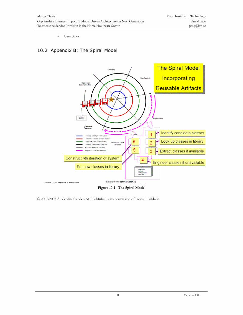
Master Thesis Royal Institute of TechnologyGap Analysis Business Impact of Model Driven Architecture on Next Generation Telemedicine Service Provision in the Home Healthcare Sector
Pascal Laue [email protected]
II Version 1.0
• User Story
10.2 Appendix B: The Spiral Model
Figure 10-1 The Spiral Model
© 2001-2003 Auldenfire Sweden AB. Published with permission of Donald Baldwin.