galvanic corrosion study on stainless steel … · and aluminum, in contact with copper, stainless...
TRANSCRIPT

AD
AD-E403 195
Technical Report ARMET-TR-08023
GALVANIC CORROSION STUDY ON STAINLESS STEEL CARTRIDGE DESIGN
Daniel P. Schmidt Donald R. Skelton
Michelle E. Malham
November 2008
U.S. ARMY ARMAMENT RESEARCH, DEVELOPMENT AND ENGINEERING CENTER
Munitions Engineering Technology Center
Picatinny Arsenal, New Jersey
Approved for public release; distribution is unlimited.
20081230024

The views, opinions, and/or findings contained in this report are those of the author(s) and should not be construed as an official Department of the Army posi- tion, policy, or decision, unless so designated by other documentation.
The citation in this report of the names of commercial firms or commercially available products or services does not constitute official endorsement by or approval of the U.S. Government.
Destroy this report when no longer needed by any method that will prevent disclosure of its contents or reconstruction of the document. Do not return to the originator.

REPORT DOCUMENTATION PAGE Form Approved OMBNo. 0704-01-0188
The public reporting burden for this collection of information is estimated to average 1 hour per response, including the time for reviewing instructions, searching existing data sources, gathering and maintaining the data needed, and completing and reviewing the collection of information. Send comments regarding this burden estimate or any other aspect of this collection of information, including suggestions for reducing the burden to Department of Defense, Washington Headquarters Services Directorate for Information Operations and Reports (0704-0188), 1215 Jefferson Davis Highway. Suite 1204, Arlington, VA 22202-4302. Respondents should be aware that notwithstanding any other provision of law, no person shall be subject to any penalty for failing to comply with a collection of information if it does not display a currently valid OMB control number. PLEASE DO NOT RETURN YOUR FORM TO THE ABOVE ADDRESS.
1. REPORT DATE (DD-MM-YYYY) November 2008
2. REPORT TYPE 3. DATES COVERED (From - April to July 2008
To)
4. TITLE AND SUBTITLE
GALVANIC CORROSION STUDY ON STAINLESS STEEL CARTRIDGE DESIGN
5a. CONTRACT NUMBER
5b. GRANT NUMBER
5c. PROGRAM ELEMENT NUMBER
6. AUTHORS
Daniel P. Schmidt, Donald R. Skelton, and Michelle E. Malham
5d. PROJECT NUMBER
5e. TASK NUMBER
5f. WORK UNIT NUMBER
7. PERFORMING ORGANIZATION NAME(S) AND ADDRESS(ES) U.S. Army ARDEC, METC Energetics, Warheads & Manufacturing Technology Directorate (AMSRD-AAR-MEE-M) Picatinny Arsenal, NJ 07806-5000
8. PERFORMING ORGANIZATION REPORT NUMBER
9. SPONSORING/MONITORING AGENCY NAME(S) AND ADDRESS(ES) U.S. Army ARDEC, ESIC Technical Research Center (AMSRD-AAR-EIK) Picatinny Arsenal, NJ 07806-5000
10. SPONSOR/MONITOR'S ACRONYM(S)
11. SPONSOR/MONITOR'S REPORT NUMBER(S)
Technical Report ARMET-TR-08023 12. DISTRIBUTION/AVAILABILITY STATEMENT
Approved for public release; distribution is unlimited.
13. SUPPLEMENTARY NOTES
14. ABSTRACT
A new ammunition design incorporates stainless steel as the cartridge case, a copper alloy bullet jacket, and an aluminum plug insert for structural support. The dissimilar materials in the new design will be physically connected (electrical contact) and may be exposed to environments that result in an electrolyte connection. Therefore, a study on the possible galvanic corrosion issues of the new ammunition design was conducted. Several different representative galvanic couples were tested. Aggressive environments were used to accelerate the reactions in an attempt to predict future corrosion issues. Testing included atmospheric exposures, constant immersion, and electrochemical analysis. At the conclusion of each test, the specimens were examined visually and microscopically to determine the extent of damage in each individual material. The results of the study did not show any significant cause for redesign, but galvanic reactions were present.
15. SUBJECT TERMS
Cartridge case Lightweight small caliber ammunition Stainless steel Galvanic corrosion
16. SECURITY CLASSIFICATION OF:
a. REPORT U
b. ABSTRACT U
c. THIS PAGE U
17. LIMITATION OF ABSTRACT
SAR
18. NUMBER OF PAGES
47
19a. NAME OF RESPONSIBE PERSON Daniel P. Schmidt 19b. TELEPHONE NUMBER (Include area
code) (973) 724-3182 Standard Form 298 (Rev. 8/98)
Prescribed by ANSI Std. Z39.18

CONTENTS
Page
Background 1
Objective 1
Experimental Procedure 1
Materials 1 Test Procedures 2
Results 4
Atmospheric Exposure 4 Constant Immersion 10 Zero Resistance Ammeter Test 15
Discussion 18
Aluminum Coupled with Stainless Steel 18 Copper Alloy Coupled with Stainless Steel 18 Carbon Steel Coupled with Stainless Steel 19
Conclusions 19
References 21
Appendices
A Area Ratio Calculations 23
B Sample Preparation 27
C Weather Data 31
D SEM/EDXA Analysis 35
Distribution List 41

FIGURES
Page
1 Galvanic couple specimens before atmospheric exposure 3
2 Uncoupled specimens (controls) before atmospheric exposure 4
3 All atmospheric specimens after initial exposure in CITY 5
4 Slight discoloration on aluminum backside that was mated with the stainless steel 6
5 Pitting of stainless steel in crevice formed from galvanic couple with aluminum and 6 plastic backing
6 Tarnishing of copper surface during atmospheric exposure 7
7 Corrosion after 3 months atmospheric exposure on copper alloy 8
8 Corrosion of carbon steel specimens during atmospheric exposure 9
9 Corrosion product on carbon steel surfaces after 3 months atmospheric exposure 9
10 Border of crevice created by nylon nut on front face of carbon steel specimen after 10 3 months of atmospheric exposure
11 Specimens removed from constant immersion in artificial seawater after 2.5 weeks 11
12 Aluminum specimens after 2.5 weeks (bottom row) and 5 weeks (top row) of 11 constant immersion in artificial seawater
13 Digital microscope images at 20x magnification of aluminum specimens after 5 12 weeks of constant immersion in artificial seawater
14 Images after 2.5 weeks of constant immersion in artificial seawater 13
15 Front sides of copper alloy specimens after being separated from coupling setups 13
16 Digital microscope images at 20x magnification of copper alloy specimens after 5 14 weeks of constant immersion in artificial seawater
17 Digital microscope image at 30x magnification of corrosion product residue from the 15 copper alloy on the stainless steel specimen after 5 weeks of immersion in artificial seawater
18 Plot of galvanic current (log A) versus time (s) for different materials coupled with 16 stainless steel in artificial seawater
FIGURES (continued)
Page
19 Plot of corrosion potential (mV versus SCE) versus time (s) for different materials 16 coupled with stainless steel in artificial seawater
20 Digital microscope images at 50x magnification of exposure areas from galvanic 17 corrosion ZRA experiments

BACKGROUND
A new ammunition design incorporates stainless steel as the cartridge case and an aluminum plug insert. There is concern that the physical contact of several materials including stainless steel, aluminum, copper alloy, and carbon steel may lead to galvanic corrosion. Galvanic corrosion results from dissimilar metals that are in electrical contact while immersed in a solution electrolyte (ref. 1). The materials in the new cartridge case design will be physically connected (electrical contact) and may be exposed to environments that result in an electrolyte connection. In certain environments, particularly with metals such as magnesium, steel, zinc, and aluminum, in contact with copper, stainless steel, or nickel, galvanic corrosion may be appreciable (ref. 2). The stainless steel cartridge case should provide corrosion resistance, but when coupled with a dissimilar material, the latter may corrode at a rapid pace resulting in non- functioning or potentially hazardous ammunition. Previous testing of the new design passed initial corrosion exposures, but long term storage is still of concern.
OBJECTIVE
The objective was to investigate the galvanic interaction between the materials used in the new ammunition design under aggressive conditions to determine if the there will be a corrosion issue in the future.
EXPERIMENTAL PROCEDURE
Materials
Small sections of the representative materials were prepared and exposed to test solutions/environments based on their relevant configuration. Table 1 shows the metals used and their representative components in the new cartridge design.
Table 1 Materials used in testing and representative components
Test material (supplier) Represents 305 stainless steel (Brown Metals Co.) Cartridge case 7075 aluminum T6 (Yarde Metals) Plug insert Copper alloy 220 (Metal Suppliers Online) Bullet jacket 1045 carbon steel (McMaster Carr) Cartridge links
The possible galvanic couples of concern are:
1. G1 = stainless steel and aluminum
2. G2 = stainless steel and copper alloy
3. G3 = stainless steel and carbon steel

4. C1 = control material with plastic backing (to mimic possible crevice corrosion)
5. C2 = control material without backing
In addition to choosing the proper materials, determining the ratio of surface area in galvanic couples is very important. A large cathode (more noble) to anode (less noble) area ratio can lead to much higher corrosion rates for the anodic material. The surface area ratio is defined as the surface area of one member of the couple divided by the surface area of the other member of the couple; only the area in contact with the electrolyte (wetted area) is used in this calculation (ref. 3). Based on technical drawings and physical measurements, the following estimates for area ratios were determined:
• Stainless steel cartridge to aluminum insert = 5 to 1
• Stainless steel to copper alloy bullet = 4 to 1
• Stainless steel cartridge to carbon steel link = 1 to 1
Further explanations of area ratio calculations are provided in appendix A.
Test Procedures
Three separate test procedures were conducted: (1) atmospheric exposure, (2) constant immersion, and (3) zero resistance ammeter testing. Control specimens were included in each test scenario to provide a comparison between the typical corrosion created from a crevice and the accelerated galvanic corrosion. Further details on specimen surface preparation are included in appendix B.
Atmospheric Exposure
Nylon rod coupled specimens (figs. 1 and 2) were placed on rack A in the corrosion instrumented test yard (CITY) located at the U.S. Army Armament Research, Development and Engineering Center (ARDEC), Picatinny Arsenal, New Jersey in compliance with ASTM G50 (ref. 4). Three sets of triplicate specimens and two sets of control specimens were exposed for 1 month, 3 months, and to be decided. Digital pictures were taken on a regular basis and post-exposure examination was conducted.
Constant Immersion
Nylon rod coupled specimens (figs. 1 and 2) were placed in 500 mL plastic containers completely submersed in ASTM D1141 (ref. 5) artificial seawater. Specimens were held vertical and evenly spaced using additional nylon rods and nuts. Separate containers were used for the aluminum-stainless steel couples and the copper alloy-stainless steel couples. One set of replicates for each specimen type were removed after 2.5 weeks of immersion and after 5 weeks of immersion. Digital pictures were taken on a regular basis and post-exposure examination was conducted.

(a) Aluminum with stainless steel
(b) Copper alloy with stainless steel
(c) Carbon steel and stainless steel
Figure 1 Galvanic couple specimens before atmospheric exposure (Materials are held together using nylon rods and nuts.)

(a) Control type 1 (with plastic backing)
(b) Control type 2 (without plastic backing)
Figure 2 Uncoupled specimens (controls) before atmospheric exposure
(Materials are held together using nylon rods and nuts.)
Zero Resistance Ammeter
This electrochemical test maintains a potential difference of zero between the anodic and cathodic materials while monitoring the galvanic current. Tests were conducted using a computer controlled zero resistance ammeter (Gamry Instruments Reference 600) and a MPM Technologies Multipurpose Corrosion Cell with ASTM D1141 artificial seawater as the electrolyte. A saturated calomel electrode (SCE) was used as the reference electrode. Tests were run for 5 hrs with data points recorded every 30 sec.
RESULTS
Atmospheric Exposure
Figure 3 shows specimens after initial exposure in the CITY. Several sets of replicates for each type were tested to accommodate removal after different exposure durations.

Controls with plastic backing
Controls without plastic backing
Figure 3 All atmospheric specimens after initial exposure in CITY

Aluminum Coupled with Stainless Steel (Atmospheric Exposure)
No significant difference was visible between the aluminum-stainless steel coupled and uncoupled materials after 1 month and 3 months of exposure. This was expected because both aluminum and stainless steel form strong passive oxide layers in the presence of oxygen in the atmosphere. These oxide layers protect the substrates from further corrosion. Only slight discoloration on the aluminum was noticed on the face that was mated with the stainless steel after 3 months of exposure (fig. 4). Some pitting was apparent on the stainless steel possibly due to the slight crevice created from the aluminum-stainless steel interface. The crevice corrosion control specimen supported this theory. Figure 5 shows the pitting.
Figure 4 Slight discoloration on aluminum backside that was mated with the stainless steel
(a) Galvanic couple with aluminum
(b) Plastic backing
Figure 5 Pitting of stainless steel in crevice formed from galvanic couple with aluminum and plastic
backing (Images were taken at 100x magnification.)

Copper Alloy Coupled with Stainless Steel (Atmospheric Exposure)
As in the case of the aluminum-stainless steel couples, the copper alloy-stainless steels materials did not corrode significantly different when coupled versus uncoupled. The surface of the copper alloy did tarnish after 2 weeks of exposure. This was apparent on the fronts of all three copper alloy specimens (fig. 6). The corrosion on the backside of the galvanic couple specimen was more evident than that of the plastic-backed specimen (fig. 7). The crevice formed in both setups appears to have contributed to the degradation, but the galvanic couple provided a stronger driving force. The stainless steel specimens (both coupled to the copper alloy and the plastic) exhibited pitting (fig. 5) from the crevice formed.
(a) Galvanic couple (copper alloy-stainless steel) after initial exposure
(b) (c) Galvanic couple (copper alloy-stainless steel) Control specimen (copper alloy-plastic backing)
after 2 weeks exposure after 2 weeks exposure
Figure 6 Tarnishing of copper surface during atmospheric exposure

(a) Face coupled to stainless steel
(b) Face coupled to plastic backing
Figure 7 Corrosion after 3 months atmospheric exposure on copper alloy
(Images on right side were taken at 100x magnification.)
Carbon Steel Coupled to Stainless Steel (Atmospheric Exposure)
As expected, the carbon steel specimens exhibited the most atmospheric corrosion degradation of all the materials. However, the corrosion was not significantly different in the coupled as compared with the uncoupled arrangement. General corrosion was apparent on the surface of all carbon steel specimens after 1 week of atmospheric exposure (fig.8a). After 3 months, the carbon steel corrosion on the galvanic couple specimen was consistent with the corrosion on the control specimen (with plastic backing) (fig. 8a and b).

(a) After 1 week
(b) (c) Galvanic couple (carbon steel-stainless Control with plastic backing
steel) after 3 months after 3 months Figure 8
Corrosion of carbon steel specimens during atmospheric exposure
The corrosion on the backside was a little more interesting. In both the coupled and plastic-backed setups, the degradation was similar although there was slightly more red corrosion product in the galvanic couple specimen (fig. 9). This could be due to the galvanic reaction between the carbon steel and the stainless steel and the penetration of water from the less tightly fitting galvanic couple setup.
m • < I-II50H JM Vin I
(a) (b) Galvanic couple specimen Plastic-backed specimen
Figure 9 Corrosion product on carbon steel surfaces after 3 months atmospheric exposure

The black iron oxide (magnetite) formed due to lack of oxygen in the crevice while red iron oxide (hematite) formed on the exposed surfaces. Figure 10 shows evidence of this on the front side of a carbon steel specimen at the border where the nylon nut created a crevice.
Area exposed to
-•
atmosphere
'2*
Area uuder ii nt
Figure 10 Border of crevice created by nylon nut on front face of carbon steel specimen after 3 months of
atmospheric exposure (Image taken at 50x magnification.)
Atmospheric Exposure Summary
For the atmospheric exposure specimens in general, it can be stated that the effect of being coupled to stainless steel did not significantly accelerate the corrosion rate. More time-of-wetness and a greater exposure to corrosive agents (chloride ions, sulfur dioxide, etc.) may have provided a more noticeable difference between coupled and uncoupled specimen degradation. Weather data for the exposure period is provided in appendix C. The final set of specimens will continued to be exposed and monitored over the next year. Weight loss will be measured upon removal of final specimens.
Constant Immersion
Aluminum Coupled to Stainless Steel (Constant Immersion)
After 2.5 weeks of immersion in artificial seawater, the galvanic coupled aluminum had a considerable large amount of white corrosion product (fig. 11). When the couples were separated for further examination, it was very clear that the galvanic couple had accelerated the aluminum corrosion rate. There was a greater amount of white corrosion product than on the uncoupled aluminum sample (with plastic backing) after 2.5 and 5 weeks of immersion (fig. 12).
10

Figure 11 Specimens removed from constant immersion in artificial seawater after 2.5 weeks
[Left - aluminum coupled with stainless steel and right - aluminum with plastic backing]
Al coupled to Stainless Steel
AI controls with Plastic Backing
IHE^aBBnEIuBftl 0t amflitraaF^m
2 JW mWW*f r-AI-0508 15W tiimiJ-..\
KODAK Coloi Control Patches
Figure 12 Aluminum specimens after 2.5 weeks (bottom row) and 5 weeks (top row) of constant immersion
in artificial seawater (Left side specimens were coupled to stainless steel and right side specimens has a plastic backing.)
11

Higher magnification digital pictures were taken to better illustrate the difference in corrosion products between the galvanic couple aluminum and the plastic-backed aluminum. Figure 13 shows there is clearly a difference in corrosion damage. The galvanic coupled aluminum has a significant amount of white corrosion product covering the surface. Alternatively, the plastic-backed aluminum has discoloration, but no corrosion product build-up. A reddish material was evident in the coupled specimen, which later turned to white with exposure to air. This material will be further investigated.
(a) Coupled with stainless steel
(b) Plastic backing
Figure 13 Digital microscope images at 20x magnification of aluminum specimens after 5 weeks of
constant immersion in artificial seawater
12

Copper Alloy Coupled to Stainless Steel (Constant Immersion)
After 2.5 weeks of immersion in artificial seawater, one set of specimens was removed for inspection. It was already apparent that the galvanic couple copper alloy was corroding more than the plastic-backed specimen. In figure 14, the blue/green corrosion product can be seen coming off the copper alloy at the copper-stainless steel interface. The surface corrosion on both specimen types is very similar (fig. 15). The area underneath the nylon nut is still untarnished.
Figure 14 Images after 2.5 weeks of constant immersion in artificial seawater
(Left side is the control copper alloy specimen with plastic backing and the right side is the galvanic couple of the copper alloy and stainless steel.)
Figure 15 Front sides of copper alloy specimens after being separated from coupling setups
(These specimens were exposed for 5 weeks in artificial seawater.)
13

Although the front sides were similar, the sides in contact with the coupling material had different results. Figure 16a shows the copper alloy that was coupled to the stainless steel corroded in distinct areas. The copper alloy specimen that was coupled to the plastic did not show as distinct of corrosion areas (fig. 16b). The damage was more spread out and not as extensive.
Intact area
(a) Coupled with stainless steel
(b) Plastic backing
Figure 16 Digital microscope images at 20x magnification of copper alloy specimens after 5 weeks of
constant immersion in artificial seawater
14

Further analysis was conducted on the corrosion product that remained on the stainless steel specimen that was coupled to the copper alloy. Figure 17 shows a closer look at the blue/green corrosion product at the corner where the two specimens met. The analysis of this corrosion product (included in appendix D) supported the idea that the corrosion product was from the copper alloy. The Energy Dispersive X-ray Analysis (EDXA) also showed that the red material contained a large amount of calcium and sulfur (possibly some type of calcium sulfate residue).
Figure 17 Digital microscope image at 30x magnification of corrosion product residue from the copper alloy
on the stainless steel specimen after 5 weeks of immersion in artificial seawater
Zero Resistance Ammeter Test
An additional test was conducted to compare the galvanic reactions of the different materials with stainless steel. In this electrochemical test, a zero resistance ammeter was used to maintain a constant potential difference of zero between the two materials of interest. The area ratios were kept equal to accommodate the test setup and the subsequent analysis.
A plot of the galvanic current recorded during the test is shown in figure 18. The current was plotted on a log scale. Higher current correlates to higher corrosion rates. From these results, it is apparent that when coupled with stainless steel (1:1 area ratio) in artificial seawater the aluminum and carbon steel corroded at a faster rate than the copper alloy. Figure 19 is a plot of the corrosion potentials as a function of time. The low corrosion potentials of the aluminum-stainless steel and carbon steel-stainless steel system demonstrate their sacrificial protection of the stainless steel. A SCE was used as the reference electrode in this system.
15

0*p«fc ftrator. fc«i (2M e«*t«v* towrt
I
imw ]
h
Al
/
\ Carbon Steel
^
Cu alloy
'«
Figure 18 Plot of galvanic current (log A) versus time (s) for different materials coupled with stainless steel
in artificial seawater
(MMMG Cwnrwn BfV1(imttHMM0VMnrtV)
X Cu alloy
Carbon Steel
r DOfTV
0«O« lOjOOM
res
Figure 19 Plot of corrosion potential (mV versus SCE) versus time (s) for different materials coupled with
stainless steel in artificial seawater
In each of the three galvanic couple ZRA experiments (aluminum-stainless steel, copper alloy-stainless steel, and carbon steel-stainless steel), the stainless steel remained intact while the other coupled material corroded. Images of this corrosion are shown in figure 20. This confirms that the galvanic current recorded was a result of the stainless steel acting as a cathode (more noble) during the ZRA experiments.
16

(a) Aluminum coupled with stainless steel
(b) Copper alloy coupled with stainless steel
(c) Carbon steel coupled with stainless steel
The circles of discoloration shown on the left side are where the electrolyte (artificial seawater) was in contact with the material.
Figure 20 Digital microscope images at 50x magnification of exposure areas from galvanic corrosion ZRA
experiments
17

DISCUSSION
Aluminum Coupled with Stainless Steel
The objective of testing aluminum coupled with stainless steel was to represent the 7075 aluminum T6 plug being inserted inside the stainless cartridge case of the new 5.56-mm ammunition design. The aluminum plug will be in contact with the cartridge case creating a potential for galvanic corrosion in the future. This study's tests showed that in the atmosphere, aluminum protects itself sufficiently when this couple is formed. However, the immersion tests may be more relevant by representing the environment within a cartridge case. The worse case scenario tested was the constant immersion in artificial seawater with a 5:1 surface area ratio (stainless steel to aluminum). When submerged and coupled with the stainless steel, the galvanic reaction caused the aluminum to corrode at a higher rate than that of the control specimen (plastic backing). It must be noted that aluminum is susceptible to chloride ion attack and this may not ever be present in a cartridge case. In addition, the environment within the cartridge case would have to provide enough moisture to sufficiently make contact between the aluminum and the stainless steel. Additional variables include changes in pH and temperature that could lead to accelerated corrosion. The propellant used in this 5.56-mm ammunition is WC844 and, therefore, the potential does exist for a pH change within the cartridge from off- gassing as a result of a sufficient change in temperature and humidity. This study did not test conditions using this propellant directly. The stainless steel may also be slightly vulnerable to pitting in a crevice condition as shown in the atmospheric test results (Aluminum Coupled with Stainless Steel section). All of these factors warrant the close monitoring of the aluminum plugs in the new design although it does not conclusively show that the plugs will corrode. A protective layer such as an anodized finish may provide further protection and/or somehow designing the plug so as not to create an electrical connection with the stainless steel cartridge case.
Copper Alloy Coupled with Stainless Steel
The objective of testing copper alloy coupled with stainless steel was to represent the copper alloy 220 bullet jacket that will be in contact with the stainless steel cartridge case of the new 5.56-mm ammunition design. The different metals in contact can create a potential for galvanic corrosion in the future. Unlike the case of the aluminum-stainless steel, the copper alloy-stainless steel may be better represented in the atmospheric exposures of this study. This is because the bullet and cartridge case are exposed to the outdoor environment at the same time. With proper humidity or precipitation, a galvanic cell could be created. This study showed that the copper alloy did not significantly corrode more when coupled with the stainless steel after 3 months of atmospheric exposure. The ZRA experiments showed that the galvanic couple had very low galvanic current rates (in the low uA's). The worst case scenario of the cartridge being completely submerged in artificial seawater for 5 weeks showed that the galvanic couple did accelerate the copper alloy corrosion. By monitoring for evidence of blue/ green corrosion product and maintaining proper storage of cartridges, this potential degradation can be avoided.
18

Carbon Steel Coupled with Stainless Steel
The objective of testing carbon steel coupled with stainless steel was to represent the 1045 carbon steel links (or similar alloy) that will be in contact with the stainless steel cartridge case of the new 5.56-mm ammunition design. The carbon steel tested in this study was not phosphated or oiled. The idea was to simulate the worst case scenario in which the link had not been properly treated or had been scratched thoroughly revealing the bare carbon steel below. Similar to the copper alloy-stainless steel couple, the atmospheric exposures conducted in this study most closely represented the real life situation that a cartridge and its links will experience. Because a severe difference was not found between the corrosion rate of the coupled steel versus the uncoupled steel, it is not a major concern. As long as proper care is taken to keep the steel links lubricated and oiled, there should not be a significant galvanic corrosion issue. In addition, any corrosion will be very visible with red corrosion product forming on the carbon steel links.
CONCLUSIONS
Testing results warrant the close monitoring of 7075 aluminum T6 plugs in the new design although it does not conclusively show that the plugs will corrode given the complicated environment within a cartridge case. A protective layer, such as an anodized finish and/or somehow designing the plug so as not to create an electrical connection with the stainless steel cartridge case, may provide further protection of the aluminum plug.
By monitoring for evidence of blue/green corrosion product and maintaining proper storage of cartridges, the potential degradation of copper alloy 220 in contact with the stainless steel cartridges cases can be avoided and should not be of major concern.
If carbon steel links are properly phosphated and treated with oil, there should not be a significant galvanic corrosion issue with the stainless steel cartridges. Any corrosion should be very visible as a red corrosion product forming on the carbon steel links.
The 305 stainless steel may be slightly vulnerable to pitting in any crevice conditions and should, therefore, be monitored.
Materials and environments used in this study were chosen to represent the new cartridge design, but surface treatments, manufacturing processes, actual environments, etc. can lead to unique results.
Continued atmospheric exposure of several galvanic couples is underway. Any new pertinent information found upon further analysis will be reported.
19

REFERENCES
1. Jones, P. A., Principles and Prevention of Corrosion, ©1996, Prentice-Hall, Inc., Upper Saddle River, NJ, pg. 168-198.
2. MIL-STD-889B, "Dissimilar Metals."
3. ASTM G71, "Conducting and Evaluation Galvanic Corrosion Tests on Metals."
4. ASTM G50, "Standard Practice for Conducting Atmospheric Corrosion Tests on Metals."
5. ASTM D1141, "Standard Practice for the Preparation of Substitute Ocean Water."
6. ASTM G82, "Development and Use of a Galvanic Series for Predicting Galvanic Corrosion Performance."
21

APPENDIX A AREA RATIO CALCULATIONS
23

SS cartridge to Al insert Since Al insert will be confined inside cartridge, the surface area in question will be the surface of the Al in contact with the propellant and the inside area of the SS cartridge. This estimation will be a worst case scenario in case the propellant acts as an electrolyte. Rough estimate based on scale drawing: Al surface in contact with propellant = inside of topless % diameter cylinder with V? height Al Area = Circumference x height + area of bottom = (71 * V2)* V% + 71 * (V4)
2 = 0.98units2
SS surface (inside of cartridge case) = cylinder with no top or bottom = 3A diameter cylinder with a 2 height SS Area = Circumference x height = {n* 3A)* 2 = 4.7 units2
Area Ratio = (4.7 / 0.98) = 4.8 ~ 5 = 5 to 1
SS Cartridge to Cu alloy bullet The portion of the Cu bullet that extends out of the cartridge will be exposed to the environment in contact with the outside portion of the SS cartridge. Because these two surfaces could be exposed to an electrolyte they will be used to determine the worst case scenario surface area ratio. Rough estimate based on picture: Cu surface extending outside of cartridge = outside surface of cone shape Cu Area = cone with 1 diameter and 1.75 length = (71 * Yi) * 1.75 = 2.8 SS surface (outside of cartridge case) = cylinder approx. 4 length with 1 diameter SS area = cylinder with 1 diameter and 4 height = (n*1)*4 = 12.5 Area Ratio = 12.5 / 2.8 = 4.4 ~ 4 = 4 to 1
SS cartridge to Carbon Steel links The stainless steel cartridges are held in phosphated steel links (M27 Links). If the entire assembly is exposed to humid or wet environments this connection could create a galvanic couple. Rough estimate based on drawings: Steel link surface = 3A of a cylinder along 3A of the cartridge length = 9/16 of total surface Stainless Steel surface (area not covered by link) = 1-9/16 = 7/16 Area Ratio = 7/9 ~ 1 = 1 to 1
25

APPENDIX B SAMPLE PREPARATION
27

Cutting - Al and Cu were cut into 1" strips with large shears - Al then cut with gravity band saw into 1" x 1" squares.
Cu then cut with Secotom into 1" x 1" squares 305 SS was cut into strips then squares using smaller shear machine 1045 Steel was cut into Vi slices with large gravity band saw
Drilling holes Drill press used to drill holes in center of each sample SS had to be flattened with hammer (place sample between two other pieces of SS and hit until lip was gone)
Polishing For Atm Exposure
- DCM Clean Air Paint Removal Tool Kit 3" Disc Sander was used with 36 and 80 grit to remove very rough edges from samples Al and Cu were polished using SiC disc sanders (240 grit) For Immersion Tool Kit was used to grind samples with circular sander to 36 grit (Al, St) Cu was polished to 180 grit on wheel sanders All specimens were cleaned with Alconox and methanol
Engraving Handheld engraver was used to put a number in the lower right corner of each specimen
29

APPENDIX C WEATHER DATA
31

Location: Corrosion Instrumented Test Yard (CITY) Picatinny Arsenal, NJ
Date Temperature [°C]
Mean Max Min
Relative Humidity
(AVE)
[%]
Dew Point (AVE)
[C]
Rainfall Total
[mm]
Solar Radiation
(AVE)
[W/m2]
UV Index (AVE)
Leaf Wetness
(AVE)
0(dry)-15(wet)
Wind Speed (AVE)
[m/s]
3M Exp Period 19.2 | 34.8 | -0.9 68 12.5 238 236 1.7 3.9 0.6
Note: Cf and S02 concentrations negligible
33

APPENDIX D SEM/EDXA ANALYSIS
35
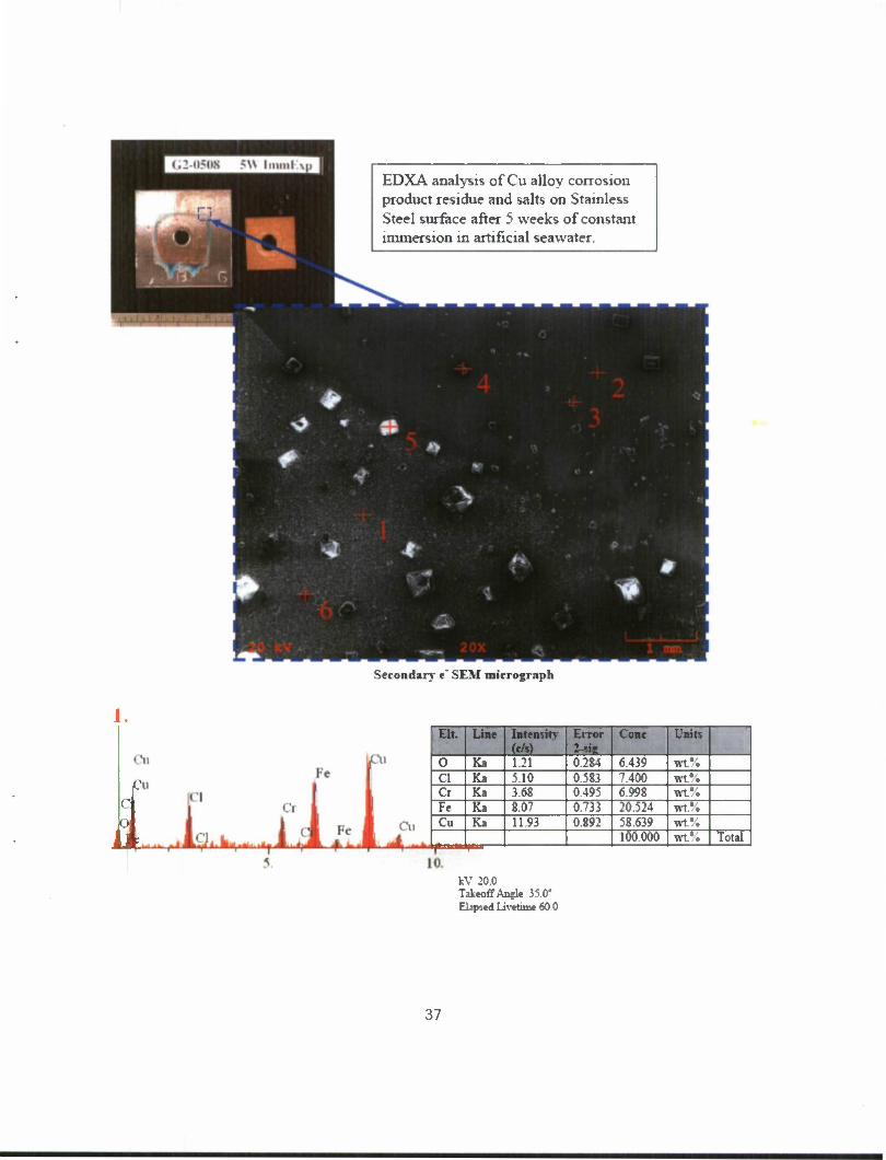
EDXA analysis of Cu alloy corrosion product residue and salts on Stainless Steel surface after 5 weeks of constant immersion in artificial seawater.
Secondary •" SEM micrograph
1.
I EH. Line Intensity
(e/s) Error 2-sie
Cone Units
0 Ka 121 0.284 6 43? wt.\ Cl Ka 5.10 0.583 7400 wt.#; Ci Ka 368 0.495 6998 wt*. Fe Ka 8.07 0.733 20.524 tft% Cu Ka 11.93 0.892 58.639 wt*.
100.000 wt.*. Total
kV 20.0 Takeoff Angle 35 0' Elapsed Livetime 60 0
37

2.
a a
I ai 4,„ i i iii t
a
Ft-
I Jui JEL^!2L £1L
Eh. Line Intensity (c/s)
Error
"I Cone Units
Cl Ka 083 0389 0832 wt.% Cr Ka 16.15 1.721 20.883 wt.% Fe Ka 34 78 2526 74.410 wt.% Cu Ka 1.00 0.428 3.874 wt.%
100.000 wt.% Total
10
W 20.0 Takeoff Angle 35.0° Elapsed Livetime 21.8
3.
-£+' ,i
<'l
I Ct Ctf* Fe Cu Oi
Eh. Line Intensity (c/s)
Error 2-sis
Cone Units
Cl Ka 58.59 2.427 76.573 wt.% Cr Ka 1.37 0.372 3.504 wt.% Fe Ka 2.24 0.474 7.277 Wt.% Cu Ka 2.28 0.479 12.646 wt.%
100.000 wt.% Total
10.
4.
i-i
i I Cl aFc Fc Qi Cu
10
38
kV 20.0 Takeoff Angle 35.0" Elapsed Livetime 39.8
Eh. Line Intensity (c/s)
Error 2-sig
Cone Units
Cl Ka 8387 6.126 98.259 wt.*. Cr Ka 0.67 0.548 1.741 wt.% Fe Ka 0.00 0.000 0.000 wt.% Cu Ka 0.00 0.000 0.000 wt.%
100.000 wt.% Total
kV 20.0 Takeoff Angle 35.0° Elapsed Livetime 8.9

r\
• •fls?/',* Ql
^iL5L •i «' i•
Eh. Line Intensity (c/s)
Error 2-sis
Cone Units
Cl Ka 73.95 1380 94733 wt.\ Cr Ka 0.76 0.546 2.119 wt% Fe Ka 0.89 0.591 3.148 wt% Cu Ka 0.00 0.000 0.000 wf.
100 000 wtS Total
Cu •^—
10 kV 20.0 Takeoff Angle 35.0° Elapsed Livetime 10 2
Eh. Line Intensity (c/s)
Error 2-sfe
Cone Units
0 Ka 4.53 0.629 41.895 wt.\ Na Ka 4.10 0.598 6801 wt.% Si Ka 0.39 0.184 0.343 wt% S Ka 28.44 1.575 24 830 wt.% Cl Ka 0.53 0.216 0578 wt.r. K Ka 2.45 0.462 2554 wt.'i Ca Ka 20.04 1.322 22.479 wt.% Cr Ka 0.29 0.159 0519 wt% Ru La 0.00 0.000 0.000 wt.\ 1 _r_—
100 000 wt.\ Total 10
kV 20.0 Takeoff Angle 35 0" Elapsed Livetizne 45.9
39

DISTRIBUTION LIST
U.S. Army ARDEC ATTN: AMSRD-AAR-EIK
AMSRD-AAR-GC AMSRD-AAR-MEE-M(IO) AMSRD-AAR-QE, D. Carra AMSRD-AAR-WS, D. Castellano AMSRD-AAR-WSF, A. D'Agosto AMSRD-AAR-WSW, M. Ford AMSRD-AAR-WSB, L. Bennett AMSRD-AAR-ME, J. Hedderich AMSRD-AAR-MEM, S. Musalli AMSRD-AAR-MEF, W. Smith AMSRD-AAR-MEX, J. Bostonian AMSRD-AAR-MEE, R. Benjamin
Picatinny Arsenal, NJ 07806-5000
Defense Technical Information Center (DTIC) ATTN: Accessions Division 8725 John J. Kingman Road, Ste 0944 Fort Belvoir, VA 22060-6218
Commander Soldier and Biological/Chemical Command ATTN: AMSSB-CII, Library Aberdeen Proving Ground, MD 21010-5423
Director U.S. Army Research Laboratory ATTN: AMSRL-CI-LP, Technical Library Bldg. 4600 Aberdeen Proving Ground, MD 21005-5066
Chief Benet Weapons Laboratory, WSEC U.S. Army Research, Development and Engineering Command Armament Research, Development and Engineering Center ATTN: AMSRD-AAR-WSB Watervliet, NY 12189-5000
Director U.S. Army TRADOC Analysis Center-WSMR ATTN: ATRC-WSS-R White Sands Missile Range, NM 88002
Chemical Propulsion Information Agency ATTN: Accessions 10630 Little Patuxent Parkway, Suite 202 Columbia, MD 21044-3204
41

GIDEP Operations Center P.O. Box 8000 Corona, CA 91718-8000
42