gallium nitride high-order mode lamb-wave resonators...
TRANSCRIPT
GALLIUM NITRIDE HIGH-ORDER MODE LAMB-WAVE RESONATORS AND DELAY-LINES
A. Ansari, H. Zhu, and M. Rais-Zadeh Electrical Engineering Department, University of Michigan, Ann Arbor, MI 48105
ABSTRACT This work reports on theoretical and experimental study of
zero-order as well as high-order symmetric and asymmetric modes of Lamb-wave resonators and delay line structures realized in single-crystalline GaN thin films. We investigate the phase velocity, dispersion characteristics, electromechanical coupling (kt
2), motional impedance (Rm) and Quality factor (Q) of different Lamb-wave modes (e.g. A0, S0, A1, S1) propagating in GaN thin films. The dispersion characteristics of these modes in GaN-based thin films are simulated and devices with different pitch sizes are fabricated and tested to compare their performance against simulation. High frequency×Q value of 3.6×10¹² is realized for devices with a pitch size of 4.6 µm, showing a very low motional impedance of Rm= 284 Ω. Depending on the propagation and dispersion characteristics of resonance modes, certain modes are shown to be dominant experimentally (S0 and A1). Furthermore, we utilize the resonance modes in a one-port resonator to build two-port delay-line structures. Such delay-line topologies operate based on travelling acoustic waves, since the free boundary (trenches) do not exist in the direction of wave propagation, reflections from the free edges are minimized, thus reducing spurious modes [1]. This work marks the first steps towards building acoustic diodes in GaN based on the “Acousto-electric Effect” [2]. Upon application of DC electric field to the piezoelectric semiconductor transmission media, acoustic wave can be amplified or attenuated depending on the direction of the electric field.
INTRODUCTION
Lamb-wave resonators, mostly realized in AlN and ZnO platforms, have been extensively used for timing and sensing applications over the past decade [3]. However, there have only been few reports on GaN Lamb-wave resonators [4,5], mainly focused on the zero-order resonance modes (S0 or A0). Lamb waves propagating in thin piezoelectric films have drawn significant attention since they combine the advantages of bulk acoustic waves (BAW) with surface acoustic waves (SAW); high phase velocities, compact designs and low motional impedances along with multiple frequency excitation defined by inter-digitated transducers (IDTs). In this work, we investigate acoustic properties of different Lamb-wave modes (e.g. A0, S0, A1, S1) propagating in GaN thin films and demonstrate high-performance Lamb-wave GaN resonators with exceptionally low motional impedances.
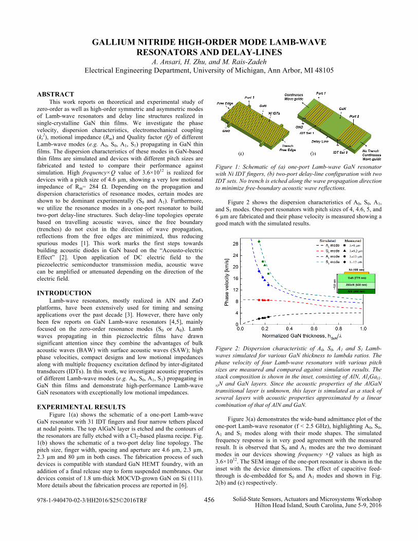
EXPERIMENTAL RESULTS Figure 1(a) shows the schematic of a one-port Lamb-wave GaN resonator with 31 IDT fingers and four narrow tethers placed at nodal points. The top AlGaN layer is etched and the contours of the resonators are fully etched with a Cl2-based plasma recipe. Fig. 1(b) shows the schematic of a two-port delay line topology. The pitch size, finger width, spacing and aperture are 4.6 µm, 2.3 µm, 2.3 µm and 80 µm in both cases. The fabrication process of such devices is compatible with standard GaN HEMT foundry, with an addition of a final release step to form suspended membranes. Our devices consist of 1.8 um-thick MOCVD-grown GaN on Si (111). More details about the fabrication process are reported in [6].
Figure 1: Schematic of (a) one-port Lamb-wave GaN resonator with Ni IDT fingers, (b) two-port delay-line configuration with two IDT sets. No trench is etched along the wave propagation direction to minimize free-boundary acoustic wave reflections. Figure 2 shows the dispersion characteristics of A0, S0, A1, and S1 modes. One-port resonators with pitch sizes of 4, 4.6, 5, and 6 µm are fabricated and their phase velocity is measured showing a good match with the simulated results.
Figure 2: Dispersion characteristic of A0, S0, A1 and S1 Lamb-waves simulated for various GaN thickness to lambda ratios. The phase velocity of four Lamb-wave resonators with various pitch sizes are measured and compared against simulation results. The stack composition is shown in the inset, consisting of AlN, AlxGa(1-
x)N and GaN layers. Since the acoustic properties of the AlGaN transitional layer is unknown, this layer is simulated as a stack of several layers with acoustic properties approximated by a linear combination of that of AlN and GaN.
Figure 3(a) demonstrates the wide-band admittance plot of the one-port Lamb-wave resonator (f < 2.5 GHz), highlighting A0, S0, A1 and S1 modes along with their mode shapes. The simulated frequency response is in very good agreement with the measured result. It is observed that S0 and A1 modes are the two dominant modes in our devices showing frequency ×Q values as high as 3.6×10¹². The SEM image of the one-port resonator is shown in the inset with the device dimensions. The effect of capacitive feed-through is de-embedded for S0 and A1 modes and shown in Fig. 2(b) and (c) respectively.
978-1-940470-02-3/HH2016/$25©2016TRF 456 Solid-State Sensors, Actuators and Microsystems WorkshopHilton Head Island, South Carolina, June 5-9, 2016
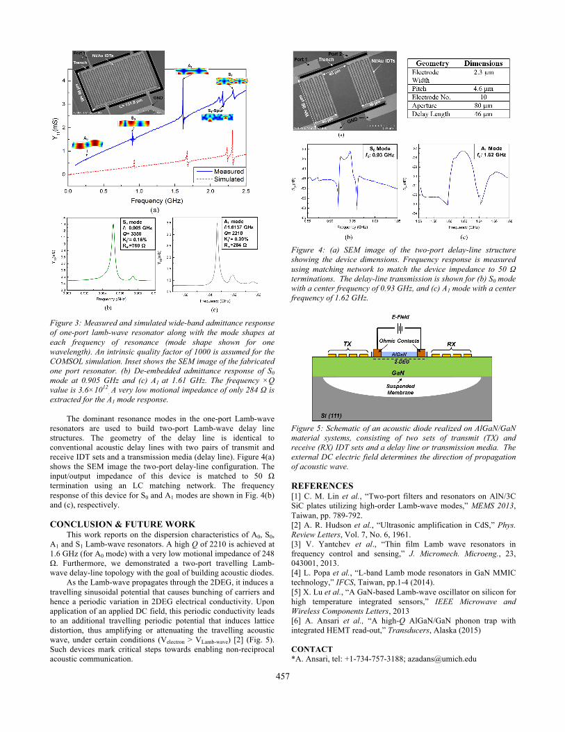
Figure 3: Measured and simulated wide-band admittance response of one-port lamb-wave resonator along with the mode shapes at each frequency of resonance (mode shape shown for one wavelength). An intrinsic quality factor of 1000 is assumed for the COMSOL simulation. Inset shows the SEM image of the fabricated one port resonator. (b) De-embedded admittance response of S0 mode at 0.905 GHz and (c) A1 at 1.61 GHz. The frequency ×Q value is 3.6×10¹²
. A very low motional impedance of only 284 Ω is extracted for the A1 mode response.
The dominant resonance modes in the one-port Lamb-wave resonators are used to build two-port Lamb-wave delay line structures. The geometry of the delay line is identical to conventional acoustic delay lines with two pairs of transmit and receive IDT sets and a transmission media (delay line). Figure 4(a) shows the SEM image the two-port delay-line configuration. The input/output impedance of this device is matched to 50 Ω termination using an LC matching network. The frequency response of this device for S0 and A1 modes are shown in Fig. 4(b) and (c), respectively.
CONCLUSION & FUTURE WORK
This work reports on the dispersion characteristics of A0, S0, A1 and S1 Lamb-wave resonators. A high Q of 2210 is achieved at 1.6 GHz (for A0 mode) with a very low motional impedance of 248 Ω. Furthermore, we demonstrated a two-port travelling Lamb-wave delay-line topology with the goal of building acoustic diodes.
As the Lamb-wave propagates through the 2DEG, it induces a travelling sinusoidal potential that causes bunching of carriers and hence a periodic variation in 2DEG electrical conductivity. Upon application of an applied DC field, this periodic conductivity leads to an additional travelling periodic potential that induces lattice distortion, thus amplifying or attenuating the travelling acoustic wave, under certain conditions (Velectron > VLamb-wave) [2] (Fig. 5). Such devices mark critical steps towards enabling non-reciprocal acoustic communication.
Figure 4: (a) SEM image of the two-port delay-line structure showing the device dimensions. Frequency response is measured using matching network to match the device impedance to 50 Ω terminations. The delay-line transmission is shown for (b) S0 mode with a center frequency of 0.93 GHz, and (c) A1 mode with a center frequency of 1.62 GHz.
Figure 5: Schematic of an acoustic diode realized on AlGaN/GaN material systems, consisting of two sets of transmit (TX) and receive (RX) IDT sets and a delay line or transmission media. The external DC electric field determines the direction of propagation of acoustic wave. REFERENCES [1] C. M. Lin et al., “Two-port filters and resonators on AlN/3C SiC plates utilizing high-order Lamb-wave modes,” MEMS 2013, Taiwan, pp. 789-792. [2] A. R. Hudson et al., “Ultrasonic amplification in CdS,” Phys. Review Letters, Vol. 7, No. 6, 1961. [3] V. Yantchev et al., “Thin film Lamb wave resonators in frequency control and sensing,” J. Micromech. Microeng., 23, 043001, 2013. [4] L. Popa et al., “L-band Lamb mode resonators in GaN MMIC technology,” IFCS, Taiwan, pp.1-4 (2014). [5] X. Lu et al., “A GaN-based Lamb-wave oscillator on silicon for high temperature integrated sensors,” IEEE Microwave and Wireless Components Letters, 2013 [6] A. Ansari et al., “A high-Q AlGaN/GaN phonon trap with integrated HEMT read-out,” Transducers, Alaska (2015) CONTACT *A. Ansari, tel: +1-734-757-3188; [email protected]
457