galaxy g3 (grade 3) user guide · vii introduction the galaxy 3 series alarm system is a...
TRANSCRIPT
User Guide
Galaxy3-144, 3-144C, 3-520, 3-520C
Honeywell Security


iii
Table of Contents .............................................................................. iiiCompliance and Approvals ............................................................. viiIntroduction ...................................................................................... viiKEYPAD INFORMATION..................................................................... 1
General ................................................................................................................ 1Number Keys (0 – 9) ............................................................................................. 1View Keys (A and B) ............................................................................................ 1Enter Key (ent) ..................................................................................................... 2Escape Key (esc) .................................................................................................. 2Hash Key (#) ......................................................................................................... 2Star Key (*) ........................................................................................................... 2Power LED ........................................................................................................... 2Banner .................................................................................................................. 2User Codes ........................................................................................................... 2
SETTING THE SYSTEM...................................................................... 3Before Setting ...................................................................................................... 3Entering A Pin - User Type 2.1 - 2.2 .................................................................... 3Entering A Pin - User Type 2.3 - 3.6 .................................................................... 3Setting groups ..................................................................................................... 3Exit time ............................................................................................................... 3Sounder ................................................................................................................ 4Zones Open .......................................................................................................... 4Final Door/Terminator ......................................................................................... 4System Set ........................................................................................................... 4Part Setting .......................................................................................................... 4Cancelling The Setting ....................................................................................... 4Group Name ......................................................................................................... 4
MAX SETTING OPTIONS .................................................................... 5Setting with User Cards/Tags/Fobs .................................................................... 5Dual Focus ........................................................................................................... 5Keyprox ................................................................................................................ 5
UNSETTING THE SYSTEM ................................................................ 6Normal Entry ........................................................................................................ 6Straying From the Entry Route ........................................................................... 6Slow Entry ............................................................................................................ 6Cancelling Alarms ............................................................................................... 6Manager Reset ..................................................................................................... 6Engineer Reset .................................................................................................... 6Unsetting with the MAX Cards ............................................................................ 6
Table of Contents

iv
ALERT CONDITIONS.......................................................................... 7MENU OPTIONS ................................................................................. 8
Full Menu ............................................................................................................. 8Quick Menu .......................................................................................................... 8Accessing The Menu ........................................................................................... 9Full Menu ............................................................................................................. 9Quick Menu .......................................................................................................... 9Omit Zones (User Type 2.3 and Above) ............................................................ 10
Purpose ........................................................................................................................ 10Selecting Omit Zones .................................................................................................. 10Viewing Eligible Zones ................................................................................................ 10Omitting Zones ............................................................................................................. 10Setting With Omitted Zones ......................................................................................... 10Vibration Zones ............................................................................................................ 10Atm 1/2/3/4 Zones ........................................................................................................ 11
Forced Set (User Type 2.3 and Above) ............................................................. 11Purpose ........................................................................................................................ 11Selecting Forced Set .................................................................................................... 11Non-omittable Zones ................................................................................................... 11
Chime (User Type 2.3 and Above) .................................................................... 12Purpose ........................................................................................................................ 12Selecting Chime .......................................................................................................... 12Chime In Operation ...................................................................................................... 12
Display Zones (User Type 2.4 and Above) ........................................................ 12Purpose ........................................................................................................................ 12Selecting Display Zones .............................................................................................. 12Address ........................................................................................................................ 12Function ........................................................................................................................ 12Status ........................................................................................................................... 13Description ................................................................................................................... 13Selecting And Viewing ................................................................................................. 13Escape ......................................................................................................................... 13
Display Log (User Type 2.4 and Above) .......................................................... 13Purpose ........................................................................................................................ 13Selecting Display Log .................................................................................................. 13Events ........................................................................................................................... 13Selecting a Date ........................................................................................................... 13Viewing Each Event ...................................................................................................... 13Additional Information .................................................................................................. 14Printing ......................................................................................................................... 14
Print (User Type 2.4 and Above) ....................................................................... 14Purpose ........................................................................................................................ 14Selecting Print .............................................................................................................. 14Codes ........................................................................................................................... 14Zones ........................................................................................................................... 14Log ............................................................................................................................... 14All .................................................................................................................................. 14Help Message .............................................................................................................. 14

v
Walk Test (User Type 2.5 and Above) ............................................................... 15Purpose ........................................................................................................................ 15Selecting Walk Test ...................................................................................................... 15All Zones ...................................................................................................................... 15Selected Zones ............................................................................................................ 15Ending Walk Test ......................................................................................................... 15
Time/Date (User Type 3.6) ................................................................................. 16Purpose ........................................................................................................................ 16Selecting Time/Date .................................................................................................... 16Changing Time ............................................................................................................ 16Changing Date ............................................................................................................. 16Advance and Retard ..................................................................................................... 16
Codes (User Type 3.6) ....................................................................................... 17Purpose ........................................................................................................................ 17Manager Code ............................................................................................................. 17Selecting Codes .......................................................................................................... 18User Codes .................................................................................................................. 18Modify Pin ..................................................................................................................... 18Modify Type ................................................................................................................... 19Modify Name ................................................................................................................ 20Time Zone .................................................................................................................... 20Temporary Codes ........................................................................................................ 21Pin Change .................................................................................................................. 21Modify Groups .............................................................................................................. 22Max Number ................................................................................................................. 23Max Function ................................................................................................................ 24Max Keypad .................................................................................................................. 24Forgive Antipassback ................................................................................................... 24Pin Warning .................................................................................................................. 25
Summer (User Type 3.6) .................................................................................... 25Trace (User Type 3.6) ......................................................................................... 26Timer Control (User Type 3.6) ........................................................................... 26Group Omit (User Type 3.6) ............................................................................... 29Remote Access (User Type 3.6) ......................................................................... 30Authorisation Access (User Type 3.6) ............................................................... 31
AVOIDING FALSE ALARMS ............................................................. 32ZONE REFERENCE TABLES .......................................................... 33ALARM AND HELP MESSAGES ...................................................... 34
Alarm In Progress ........................................................................................................ 34Pa Reset Required ...................................................................................................... 34Manager Reset Required ............................................................................................ 34Engineer Reset Required ............................................................................................ 34No Entries .................................................................................................................... 34Invalid Selection ........................................................................................................... 34Invalid Code ................................................................................................................. 34Technistore Reset ........................................................................................................ 34No Modules Added ....................................................................................................... 34
INSTALLER DETAILS ....................................................................... 35

vi

vii
INTRODUCTION
The Galaxy 3 Series alarm system is a microprocessor controlled system which has beendesigned using the latest software and hardware technology.
First and foremost, the Galaxy 3 Series meets all your security needs. The engineer willprogram and commission the system to your own exacting requirements.
Warning:
There are no user serviceable parts inside. Please refer all servicing to a qualified installer.
Compliance and Approvals
Public Switched Telephone Network (PSTN) approval
The equipment has been approved to Council Decision 98/482/EC for Pan -European singleterminal connection to the Public Switched Telephone Network (PSTN). However due todifferences between the individual PSTNs provided in different countries the approval doesnot, of itself, give an unconditional assurance of successful operation on every PSTN networktermination point.
In the event of problems contact the equipment supplier in the first instance.
The Galaxy is designed to interwork with the following networks:
Austria France Italy Norway Switzerland
Belgium Greece Liechtenstein Portugal United Kingdom
Denmark Iceland Luxembourg Spain * Germany
Finland IrelandThe Netherlands Sweden
* May have interworking difficulties.
NOTE: Contact the equipment supplier before using the Galaxy on any network notlisted.


1
KEYPAD INFORMATION
General
The Galaxy Alarm system is controlled by Galaxy Mk7 Full Alpha Liquid Crystal Display(LCD) keypads. A maximum of 16 keypads may be connected to the Galaxy 3-144 controlpanels. A maximum of 32 keypads may be connected to the Galaxy 3-520 control panels.
Number Keys (0 – 9)
These keys are used to enter the code and to select and modify options.
Before carrying out operations on the system, users must identify themselves with a PersonalIdentification Number (PIN). This number is at least a 4 digit number selected from keys0 - 9.
The number keys are also used where groups are programmed on the system permittinggroups (areas) to be set or unset.
View Keys (A and B)
These keys have been programmed to activate one of the system options. Pressing the A > keyafter a valid code has been entered starts the full set routine. Pressing the < B key after a validcode has been entered starts the part set routine.
Once a system option has been selected, the A > or < B keys can be used to operate as viewkeys, stepping forwards (A >) or backwards (< B) through lists of information. Holding downa view key while viewing an option list, rapidly displays each item in the list, permitting quickaccess to the information.
1 2 3 A
4 5 6 B
7 8 9 ent
* 0 # esc
LCD Display
Number Keys
View keys
Enter Key
Escape Key
Hash Key
Power LED
Star Key
GALAXY 520 V5.0008:58 TUE 22 NOV
2
Enter Key (ent)
The ent key accepts and processes entered data. Valid actions are performed and the nextoption is accessed.
Escape Key (esc)
The esc key aborts the current option to return to the previous option level. Any optionmodification made prior to the option being aborted is erased. Successive pressing of the esckey returns the user to the start display (known as the BANNER).
The esc key also aborts the setting routine if pressed during the exit time.
Hash Key (#)
The # key is used to display additional choices for certain options, e.g. ADVANCE/RETARDthe time in the Time/Date option.
This key is also used as the user duress key (by pressing twice following a valid codeentry).
Star Key (*)
The * key is used to provide additional features for certain options, e.g. printing the event logor deleting entries.
Power LED
The green power LED remains lit whenever the keypad is connected to a mains powersupply. A mains power failure is indicated by the LED flashing slowly. The LED flashesrapidly if the battery voltage falls below the minimum threshold or if one of the fuses on thecontrol panel PCB blows.
Banner
The banner is the display shown on the keypad, e.g. Galaxy 520 V5.00 (with the time anddate on the bottom line). This is shown at all times when the system is unset, unless the menuis being accessed or an alarm or help message is on the display. The banner can be changedby the engineer. In the set condition the banner is normally blank.
User Codes
The user code is a unique PIN (Personal Identification Number) of at least 5 digits in length.The PIN identifies the user to the Galaxy Alarm panel and allows operation of the system.

3
SETTING THE SYSTEM
Before Setting
Before setting the system ensure all doors and windows are securedand areas protected by movement detectors are free from obstruction.
Entering A Pin - User Type 2.1 - 2.2
As each digit is entered the keypad responds with a bleep and displaysa *. When all the digits are entered, press the ent or A > key to start thesetting routine.
Entering A Pin - User Type 2.3 - 3.6
As each digit is entered the keypad responds with a bleep and displaysa *. When all the digits are entered press the A > key to start the settingroutine.
Setting groups
Where group choice has been assigned to the PIN, select which groupshave to set as part of the setting routine. The set status of each group isdisplayed on the keypad screen. Possible status options are :-
R = Ready (Groups is unset, and all zones are closed)
F = Faulted (Group is unset, and at least one zone is open)
S = Set (Group is set)
L = Lockout (Group is locked out, and cannot be unset)
Select which groups have to be to set by entering the number of thegroup. For example, to set groups 2 and 3 press keys 2 and 3 . Thedisplay changes to indicate the groups selected for setting. Pressingthe ent key starts the setting routine for the specified groups.The Galaxy 3-520 has more than 8 groups. If the user has groupchoice, the available groups will be displayed at the keypad follow-ing a valid code + A >. The groups will be displayed showing A1 toA8. Use both A > and < B keys to scroll to the various sets ofgroups. If the user does not have group choice, entering the PIN andA > will cause all groups assigned to the user to set.
Exit time
If all the system zones are closed when the setting routine is started,the display indicates the remaining time, in seconds, to vacate thepremises. Exit the building using the agreed route.
TIMED SET 120
Code + ent Code + A
SET A12345678Groups UUU-----
SET A12345678Groups SUU-----
TIMED SET 120
Code + A
1
ent
SET A12345678Groups USS-----
SET B12345678Groups USS-----
TIMED SET 60
Code + A
A Key
ent

4
Sounder
During the setting period the sounder emits a continuous tone if all ofthe zones are closed. If a zone is opened during the setting period, thesounder begins to pulse. The sounder also pulses during the last 25%of the setting time to indicate time running short.
Zones Open
The exit time will reset should any zones be open or opened duringsetting. The display will indicate the number of zones open and inviteviewing. Closing the zones will restart the exit time. An alarm will begenerated if setting is not completed before the Fail to Set period ex-pires. (Fail to Set; programmed by engineer).
Note: Before closing the open zone, press esc to abort the settingroutine. The ESC TO ABORT message will flash as areminder.
Final Door/Terminator
The setting procedure can be manually completed by either closing theFINAL door or by pressing the TERMINATOR button.
System Set
When time has expired or a manual termination is made, the systemwaits four seconds before setting. The sounders emit two long tones toconfirm that the system is set. The keypad briefly displays the messageSYSTEM SET, before returning to the banner.
Part Setting
To Part Set the system press the < B key after the PIN. Only the zoneswhich have the PART attribute enabled are set. All other setting featuresare the same.
Cancelling The Setting
The setting routine can be aborted by pressing the esc key before thesystem sets.
Group Name
Press * and # keys simultaneously when groups are displayed on thekeypad (when setting for example), will display the name of thegroup . The group name should be programmed by the installationengineer. Press the * and # keys to return to the group display.
SET A12345678Groups RRRRRRRR
A1 OFFICE AREA R[<] [>] #=CHANGE
* + #
3 zones open[<] [>] to view
PART SET 120
PIN + B
5
MAX SETTING OPTIONS
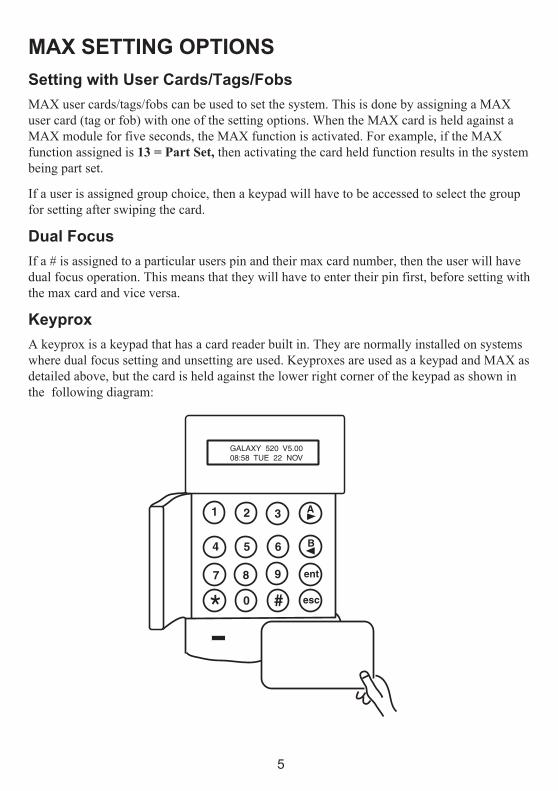
Setting with User Cards/Tags/Fobs
MAX user cards/tags/fobs can be used to set the system. This is done by assigning a MAXuser card (tag or fob) with one of the setting options. When the MAX card is held against aMAX module for five seconds, the MAX function is activated. For example, if the MAXfunction assigned is 13 = Part Set, then activating the card held function results in the systembeing part set.
If a user is assigned group choice, then a keypad will have to be accessed to select the groupfor setting after swiping the card.
Dual Focus
If a # is assigned to a particular users pin and their max card number, then the user will havedual focus operation. This means that they will have to enter their pin first, before setting withthe max card and vice versa.
Keyprox
A keyprox is a keypad that has a card reader built in. They are normally installed on systemswhere dual focus setting and unsetting are used. Keyproxes are used as a keypad and MAX asdetailed above, but the card is held against the lower right corner of the keypad as shown inthe following diagram:
GALAXY 520 V5.0008:58 TUE 22 NOV
1 2 3 A
4 5 6 B
7 8 9 ent
* 0 # esc

6
UNSETTING THE SYSTEM
Normal Entry
Unsetting starts immediately when the FINAL door is opened or anENTRY zone is activated. The sounder pulses slowly and the user mustgo directly to the keypad and enter a valid PIN, followed by A>, <B orent. Users with group choice, will access the UNSET screen followingPIN entry. This permits the user to unset specific groups. To return tothe SET screen press ent.
Straying From the Entry Route
Go directly to the keypad when entering the building. If the user straysinto a protected area and activates a zone, an alarm will occur. Thepolice may be called out and the system will have to be reset.
Slow Entry
Enter a valid PIN before the entry time expires. If the entry time expiresbefore a valid PIN is entered, then an alarm will occur. The sounderbegins to pulse quickly when 75% of the entry time has elapsedindicating time is running short.
Cancelling Alarms
To cancel an alarm, enter a valid PIN followed by ent at the keypad.The keypad displays details of the zone activated. When more than onezone is activated, details can be viewed using A > or < B. Press ent toreturn to the banner. Certain types of alarms, once cancelled, require acode with the appropriate reset authorisation to be entered. The systemprompts for a valid reset code by displaying Manager Reset Re-quired or Engineer Reset Required on the keypad.
Manager ResetEntering a manager type PIN followed by ent, resets the systemfollowing an alarm activation.
Engineer ResetCertain types of alarm require an engineer to visit the site and, afterinvestigation, reset the system. In such cases, the system cannot be resetuntil the engineer reset has been carried out.
Unsetting with the MAX Cards
If any of the groups assigned to the MAX are set, then swiping theMAX module with a card unsets the groups. Group choice and dualfocus operation, where implemented will apply as per setting instruc-tions.
Galaxy 520 V5.0015.49 MON 18 Nov
PIN + ent
4 ALARMS[<] [>] to View
PIN + ent
CALL MANAGERRESET REQUIRED
CALL ENGINEERRESET REQUIRED

7
ALERT CONDITIONSWhen a fault condition occurs in the unset state, an alert condition is activated. This consistsof an intermittent beep at the keypad and/or a visual alert on the keypad. A user should entertheir code at the keypad and press ent.The fault or faults will be shown. Use the A>and <Bkeys to scroll through multiple faults.

8
MENU OPTIONSThe Galaxy 3 Series provides various menu options for modifying the functional perform-ance of the system.
There are two menu structures:
Full Menu
Only accessed by authorised users including the master manager code and by the engineer.
Quick Menu
A selection of options from the full menu. The quick menu is the default menu access for alluser codes (type 2.3 and above) except the master manager and engineer.
Table 1. Menu Options
epyTresU uneMkciuQuneMlluF
3.2epyT 4.2epyT 5.2epyT 6.3epyT
3.2 timO=0senoZ gnitteS=01 yalpsiD=02 tseT=03 yfidoM=04
3.2 decroF=1teS
timO=11senoZ
yalpsiD=12senoZ tseTklaW=13 etaD/emiT=14
4.2 emihC=2 teSdemiT=21 yalpsiD=22goL stuptuO=23 sedoC=24
4.2 yalpsiD=3senoZ teStraP=31 metsyS=32 remmuS=34
4.2 yalpsiD=4goL
decroF=41teS tnirP=42 ecarT=44
4.2 tnirP=5 emihC=51 sseccA=52srooD
remiT=54lortnoC
5.2 klaW=6tseT teStnatsnI=61 puorG=64
timO
6.3 =7etaD/emiT
tnatsnI=71traP
etomeR=74sseccA
6.3 sedoC=8 teSemoH=81 sseccA=84noitasirohtuA
6.3 remmuS=9 tesllA=91

9
Accessing The Menu
To access the menu enter a valid code and press the ent key. If there are any outstandingsystem faults, these will be displayed first. Where there is more than one fault a > symbolwill be displayed and the scroll keys can be used to view them. Pressing the ent key againtakes the display into the menu. The Full Menu or Quick Menu is accessed, depending on theuser type.
Note: 1. If the user does not have group choice, all groups assigned to the user code must be unset.
2. If the user has group choice, only the group that the FINAL or ENTRY zone is assigned to in unset.
3. If there are no groups, then the system must be unset.
Full Menu
The Full Menu has a hierarchy of four structures contained within it. Each structure isaccessible by an increased user code type.
Quick Menu
The Quick Menu offers users type 2.3 and above a selection of up to 10 options, numbered 0– 9. The required option is selected by entering the option number (0 – 9) or by using the A> or < B keys to display each option.
The menu options (as with all Galaxy lists) are circular, therefore menu option 9 is followedby menu option 0.
The following Quick Menu options are the factory default settings. Each option is describedin the following pages.

10
Omit Zones (User Type 2.3 and Above)
PurposeThis option allows the user to omit zones before setting the system.Zones must be eligible for omission otherwise they will not be displayed.
Note: Zones remain omitted for one set period only.
Selecting Omit ZonesEnter the QUICK MENU. The 0=OMIT ZONES option is displayed.Press the ent key to select this option.
Viewing Eligible ZonesWhen the Omit Zones option is selected the first zone eligible foromission is displayed. The eligible zones can be viewed by pressingthe A> or <B keys. The zones eligible for omission can be rapidlyviewed by holding down either of these keys.
Omitting ZonesOnce the zone to be omitted is shown on the display, press the # key.The display indicates that the zone is omitted. A> and <B keys canthen be used to select other zones to be omitted using the same method.
Note: A zone is omitted from the system as soon as the # key ispressed. The system does not have to be set.
Setting With Omitted ZonesWhen the list of omitted zones is complete the setting routine is startedby pressing the ent key. The system starts to set and the display indicateshow many zones have been omitted. Alternatively the esc key can beused to return to the menu options. Zones that have been omitted remainomitted even after using the esc key.
Note: All zones omitted are recorded in the log against the user.
Vibration ZonesIf the omitted zone is a vibration zone, then all zones of this type (inall groups) will be block omitted. The vibration zones remainomitted until manually reinstated. Unsetting the system does notreinstate vibration detectors.
ZONES OMITTED14:35 TUE 17 DEC
1 OMITTED 120
ent
#
esc
1004 SECURITYOMITTED ENT=SET
0 = OMIT ZONES[ent] to select
PIN + ent
1003 A1 INTRUDER#=OMIT ENT=SET
ent
1004 SECURITY#=OMIT ENT=SET
>A

11
Atm 1/2/3/4 ZonesATM zones are omitted by entering one of the ten ATM codes (last 10users). To select this option enter an ATM code followed by the entkey. Use the A> key to scroll through the four ATM zone options(ATM1 to ATM4) and select by pressing the ent key. A preprogrammedATM delay time will expire before omitting all ATM zones with theselected ATM zone type. The zones will be omitted for the duration ofthe ATM time-out period and the remaining time in minutes will bedisplayed on the initiating keypad. A warning is given ten and fiveminutes before the zones are reinstated. The ATM Time-out periodcan be extended by entering an ATM code and selecting 1=ResetAccess. To manually reinstate ATM zones, enter an ATM code andselect 2=Abort Access.
Forced Set (User Type 2.3 and Above)
PurposeWhen enabled, the Forced Set option allows the user to automaticallyomit zones, eligible for omission, which are open when the systemsetting routine is started. Zones omitted in this way remain omitted forone set period only.
Selecting Forced SetAccess the QUICK MENU. Press key 1 followed by the ent key. Thedisplay indicates how many zones have been omitted and the numberof seconds left before setting.
Non-omittable ZonesSome open zones may not be eligible for omission from the system. Inthis case the display indicates which zones are open and the exit time isreset. These zones must be closed before setting can continue.
1=RESET ACCESS2=ABORT ACCESS
ATM PIN + ent
ACCESS TIMEOUTATM-2 10 mins
[ent] to Select1=ATM-1
ATM PIN + ent
[ent] to Select2=ATM-2
>A
ent
DELAY ACCESSATM-2 12 mins
1
0 = OMIT ZONES[ent] to Select
1
3 OMITTED 120
ATM PIN + ent
1 = FORCED SET[ent] to Select
ent
2 zones open[<] [>] to View

12
Chime (User Type 2.3 and Above)
PurposeThe Chime mode is switched on and off by this option. When theChime mode is on, any zones that have been programmed by theengineer for chime will activate momentarily when opened.
Note: Your system may not require any zones of this type.
Selecting ChimeEnter the QUICK MENU. Press key 2 followed by the ent key. Thedisplay shows the ON/OFF status of the Chime mode. Press the >Akey to toggle between the states and press the ent key to accept theselection.
Note: Keys 1 AND 0 can also be used to select ON and OFFrespectively.
Chime In OperationWhen switched ON, the Chime mode remains active until switchedOFF again. Zones that have been programmed with the chime attributeby the engineer continue to chime when they are activated.
Note: The Chime mode is suspended while the system is set orduring an alarm.
Display Zones (User Type 2.4 and Above)
PurposeThis menu option provides the user with a method of accessing theDisplay Zones mode and checking each zone for its description andcurrent status.
Selecting Display ZonesEnter the QUICK MENU. Press key 3 followed by the ent key. De-tails of the first zone (1001) are displayed.
AddressThe zone address provides a unique four digit address number used foridentification and selection, e.g. 1026 - line 1, RIO 02, zone 6.
FunctionThe zone function is displayed and identifies the operation of the zone,e.g. INTRUDER, FIRE.
0 = OMIT ZONES[ent] to Select
2 = CHIME[ent] to Select
PIN + ent
> A
CHIME MODE0 = OFF
2
ent
CHIME MODE1 = ON
ent
0 = OMIT ZONES[ent] to Select
3 = DISPLAY ZONES[ent] to Select
PIN + ent
1001 INTRUDERCOMPUTER ROOM
ent
3

13
StatusThe current status of the zone is displayed as circuit information, e.g.Open or Closed. This information alternates with function information.
DescriptionThe zone description, if programmed, is displayed on the bottom lineof the display. The descriptor is assembled from alpha-numeric textand describes the zone in detail, e.g. West Office Door.
Selecting And ViewingSelecting the Display Zones option displays the first zone addressavailable on the system. Other zones can be viewed sequentially byusing the >A or <B keys. Zones can also be displayed by entering theaddress of the zone: enter the line, RIO and zone number (4 digits).Press the # key to display the circuit resistance in ohms and RIO voltage(if hardwired).
EscapeThe esc key aborts the option and returns to the option menu.
Display Log (User Type 2.4 and Above)
PurposeThe Display Log option provides the user with a means of viewing thesystem history. Events are recorded in detail and stored in the non-volatile memory.
Selecting Display LogEnter the QUICK MENU. Press key 4 followed by the ent key.Details of the most recent event to be logged are displayed.EventsThe events available for display include details of setting, unsettingand alarms. Each event is timed and date stamped.
Selecting a DateHold down one of the view keys, the dates held in the log are rapidlystepped through. The A> key moves forward through the dates and the<B moves backwards. Stopping at the required date reveals the firstevent for that date.
Viewing Each EventThe entire events of any one date can be viewed by progressivelystepping through the events using the A> and <B view keys. *If the user has group choice enabled, the groups will display. Events foreach group can be displayed by entering the group number.
1001 INTRUDERCOMPUTER ROOM
2+1
1021 SECURITYCASHIER DOOR
esc
0 = OMIT ZONES[ent] to Select
4
4 = DISPLAY LOG[ent] to Select
ent
PIN + ent
LOG A12345678Groups YY------
LOG A12345678Groups NN------
1 + 2
ent
08:53 TUE 22 NOVAC FAIL-RIO108
MON 21 NOV 1999
B (hold)
MON 20 NOV 1999
release B

14
Additional InformationThe # key can be used to reveal additional information on some typesof events. This information is displayed on the bottom line. Theinformation includes details such as zone descriptors, user types andwhich keypad was used.
PrintingIf a serial printer is connected to the system, a system history can beprinted by pressing the * key. The system will print from the event ondisplay until the most recent event.
Print (User Type 2.4 and Above)
PurposeThe Print option gives the user the opportunity to get a hard copyprint-out of the system details. This option requires a serial printer tobe connected to the system.
Selecting PrintEnter the QUICK MENU. Press key 5 followed by the ent key. Thesystem print options are displayed. Pressing the esc key aborts thePRINT option.CodesPress key 1 to start the print-out of all the codes, giving the usernumber, name, level and length of code.
ZonesSelect the Zones option to print-out the details of each zone in thesystem. The zone address, function, and descriptor is printed. Presskey 2 to select this option.LogThe entire LOG can be printed out by selecting key 3. The print-outconsists of up to 1000 events depending on panel type, and detailsthe time and date of setting, unsetting and alarms.AllAll the options (CODES , ZONES, and LOG) can be printed out byselecting the ALL option. Pressing key 4 delivers a print-outstarting with user codes.Help MessageIf a print-out is started without a printer being connected and on-line,the display indicates that the printer is off-line.
release <B
16:31 SUN 20 NOVFULL SET USR 98
16:31 SUN 20 NOVKOO L6 A1-------
#
esc
*
0 = OMIT ZONES[ent] to Select
5
5 = PRINT[ent] to Select
PIN + ent
ent
PRINTING CODESESC to abort
1=CODES 2=ZONES3=LOG 4=ALL
1
PRINTING ZONESESC to abort
PRINTING LOGESC to abort
3
PRINTING ALLESC to abort
4
2
PRINTER off-lineESC to abort

15
Walk Test (User Type 2.5 and Above)
PurposeThe Walk Test option provides a method of testing the zones toensure that they are operating correctly. There are two optionsavailable:1. All zones can be tested2. Selected zones can be tested
In both cases the sounder indicates an open zone. The test is recorded inthe log. Wire-free zones also show the received signal strength as apercentage
Selecting Walk TestEnter the QUICK MENU. Press the key 6 followed by the ent key.When Walk Test is selected, Test All Zones or Selected Zonesdisplays.
All ZonesChoosing All Zones (press key 1) starts the test immediately. Noselection is necessary as all valid zones are included in the test. Thesounder operates whenever a zone is opened and stops when all zonesare closed.
Note: The Test All Zones option only tests zones which canbe omitted from the system.
Selected ZonesChoosing the Selected Zones option by pressing key 2 displays thefirst zone on the system. Each zone is displayed in turn by using the >Aor <B keys. When the zone to be included in the test is displayed, pressthe # key. Other zones can be included in the test in the same manner.When all of the required zones have been selected, press the ent key tostart the Walk Test.
Note: The Selected Zones option includes non-omittablezones.
Ending Walk TestTo abort the walk test option press the esc key, otherwise the walk testoption remains active for 20 minutes after the last key press.
0 = OMIT ZONES[ent] to Select
6
6 = Walk Testent to select
ent
PIN + ent
WALK TEST ACTIVEESC to abort
1=TEST ALL ZONES2=SELECTED ZONES
1
1001 FINAL#=TEST ENT=START
NO ENTRIES
2
>A
1002 EXIT#=TEST ENT=START
1002 EXITTEST ENT=START
#
ent
16
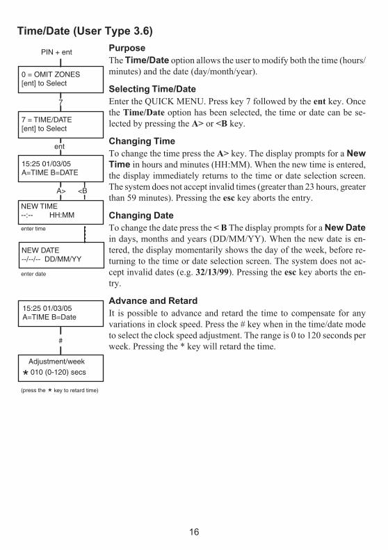
Time/Date (User Type 3.6)
PurposeThe Time/Date option allows the user to modify both the time (hours/minutes) and the date (day/month/year).
Selecting Time/DateEnter the QUICK MENU. Press key 7 followed by the ent key. Oncethe Time/Date option has been selected, the time or date can be se-lected by pressing the A> or <B key.
Changing TimeTo change the time press the A> key. The display prompts for a NewTime in hours and minutes (HH:MM). When the new time is entered,the display immediately returns to the time or date selection screen.The system does not accept invalid times (greater than 23 hours, greaterthan 59 minutes). Pressing the esc key aborts the entry.
Changing DateTo change the date press the < B The display prompts for a New Datein days, months and years (DD/MM/YY). When the new date is en-tered, the display momentarily shows the day of the week, before re-turning to the time or date selection screen. The system does not ac-cept invalid dates (e.g. 32/13/99). Pressing the esc key aborts the en-try.
Advance and RetardIt is possible to advance and retard the time to compensate for anyvariations in clock speed. Press the # key when in the time/date modeto select the clock speed adjustment. The range is 0 to 120 seconds perweek. Pressing the * key will retard the time.
0 = OMIT ZONES[ent] to Select
7
7 = TIME/DATE[ent] to Select
PIN + ent
ent
15:25 01/03/05A=TIME B=DATE
NEW TIME--:-- HH:MM
enter time
enter date
NEW DATE--/--/-- DD/MM/YY
A> <B
15:25 01/03/05A=TIME B=Date
Adjustment/week010 (0-120) secs
#
(press the
* key to retard time)*

17
Codes (User Type 3.6)
PurposeThe Codes menu option enables the managers, (user type 3.6), toassign, modify and delete the codes that allow users to operate andaccess the system. The codes option is divided into two sub–menus:
1. User CodesSub divided into 10 menus (depending on whether the group andMAX Mode options are enabled) that determine all of the accessinformation for users with Personal Identification Numbers (PINs).This menu also assigns MAX details to user numbers.
2. Pin Warning
This option determines the warning period given to users prior tothe programmed Pin Change date.
Note: The valid period for Pin Change codes is programmed bythe installation engineer.
Manager CodeThe manager code is authorised to:• Program the USER CODES option for each of the user codes.• Allocate other codes to manager type 3.6.• Modify the manager PIN (the manager PIN cannot be deleted)• Assign the MAX features to the code.
The manager code defaults to group choice when groups are ena-bled. The manager is able to toggle the group choice option on andoff (using the * key) as required.The manager code defaults to accessing the quick menu.
Note: The MAX is the Proximity Access Reader which can beconnected to the Galaxy system. This also refers to theMAX3, the enhanced version of the MAX.
0 = OMIT ZONES[ent] to Select
8
8 = CODES[ent] to Select
PIN + ent
ent
CODES1 = User Codes
>A
CODES2 = PIN Warning

18
Selecting CodesEnter the QUICK MENU. Press key 8 followed by the ent key.
User CodesWhen the Codes option has been selected, press key 1 to access UserCodes. Display each of the user numbers using key A>. Each usernumber offers options for PIN, level, name and where applicable timezones and groups. When the user number to be modified is displayed,press the ent key to access the Modify Pin option.
Modify PinThe Modify Pin option allows a pin to be assigned to a user or anexisting PIN to be modified. The PIN must be a four, five or six digitnumber that is unique to the system. If a duplicate PIN is assigned,the message Duplicate Entry is displayed. As each digit is enteredit appears on the bottom line of the display. Pressing the * key erasesthe last digit displayed. Continued pressing of the *key will erase allof the digits. When the correct PIN has been assigned press the entkey to accept the programming and return to the previous menu level.
When a PIN has been assigned to a user number, a solid box ( ) isdisplayed on the line of the user number details screen.
• Deleting a PinExisting PIN entries can be completely erased using the * keyinstead of a digit entry. When there is no PIN assigned to a usernumber a hollow square ( ) is displayed in the top line of theusers details screen.• Assigning Dual CodesTo program a user code as a Dual Code press the # key whiletheModify PIN option is selected. The # displays at the start ofthe assigned user PIN e.g. #5678. When a PIN has been as-signed as a dual code two solid boxes ( ) are displayed in thetop line of the users details screen.• Dual Codes OperationEntry of a single dual code cannot gain access to the menu, setor unset the system. The message NO ACCESS – ADDI-TIONAL CODE is displayed. A second dual code must beentered within 60 seconds to access the menu, set or unset thesystem. Dual codes can be of different levels. The highest levelcode entered determines the access level to the system.A single entry of a dual code, without a second dual code entrywithin 60 seconds, results in an Illegal Code record in theEventLog. All outputs programmed as Illegal Code are acti-vated.
0 = OMIT ZONES[ent] to Select
8
8 = CODES[ent] to Select
PIN + ent
ent
CODES1 = User Codes
ent
001 USERL3
ent
[ent] to Select1 = Modify PIN
ent
001 PIN > 5678
ent
Indicates Dual Code
001 USER L3
001 PIN > #5678

19
Modify TypeEach user is assigned an access type which determines the menuoptions available to the user (see p.7, Table 1. Menu Options). Onselecting this option, enter the type to be assigned to the user andpress the ent key to accept the programming and return to the previousmenu level. See Table 2. User Access Levels, for access availability.
• Duress CodeIf the # key is pressed while Modify Level is accessed, then thecurrent code is assigned as a Duress Code. There is no limit to thenumber of codes which can be assigned as Duress. Entering a duresscode at any time activates outputs programmed as Duress or PA.
Any valid PIN followed by # # ent (the ent key can be replaced byeither the A> or <B key) can be used as a Duress Code.
Table 2. User Access Levels
1-13105NEleveL
epyT ytilibaliavAsseccA
1 †0.1 drauG noitporehtoon–yromemtneveotnideretnE
2 †1.2 renaelC metsysehttesylnonaC
2 †2.2 rekateraC metsysehttesnudnatesylnonaC
2 3.2 sresU 91-11snoitpouneM
2 4.2 sresU 92-11snoitpouneM
2 5.2 sresU 93-11snoitpouneM
2 ‡6.3 reganaM 94-11snoitpouneM
3 ‡7.3 reenignE 17-11snoitpouneM
3 ‡8.3 etomeR 17-11snoitpouneM
†‡
snoitcnufunemotsseccaoNsedoceerhttsaleht(sedocetomerdnareenigne,reganamehT.demmargorperebtonnachcihwsepytdexifevah)metsysehtno
0 = OMIT ZONES[ent] to Select
8
8 = CODES[ent] to Select
PIN + ent
ent
CODES1 = User Codes
ent
[ent] to Select1 = Modify PIN
ent
>A
[ent] to Select2 = Modify Level
ent
001 Level >_3
ent
001 USERL3

20
• Quick MenuAll user codes default to the quick menu. This menu is made up ofa selection of ten options (0 – 9) from the menu options 11 – 49.The user code type controls access to the quick menu. Any usercan be upgraded from the quick menu to the full menu by assigninga * to the user while the Modify Level option is accessed. Thereforea user with a type *2.5 would have access to the full menu fromoptions 11 – 32. No code can access both menus.
Note: The master manager code defaults to the full menu.
Modify NameThis allows a name to be assigned to the user (maximum 6 characters).Each of the user codes default to the name USER and the managerdefaults to MGR. The manager name cannot be changed. On selectingthe Modify Name option, a section of the alpha-numeric that can beassigned to the user name is displayed on the bottom line of the keypad;the cursor flashes on the letter L. Press * to erase the letters of thedefault or previous name. When the previous name has been erased,use the A> or <B keys to move the cursor to the first letter of the nameand press the ent key. The selected character appears on the top line,continue this process until the name is completed. The # key togglesbetween upper and lower case characters and the system library. Pressesc to save the name and exit.Time ZoneManagers can allocate time zones to user PINs when TIMERS havebeen programmed by the engineer. Time zones are used to disable theuser PIN during the times (ON to OFF) programmed in TIMER Aand B.
When 4 = TIME ZONE displays, press the ent key . Using the A> keyselect the time zones option to be allocated to the PIN. The followingtime zones options are available:
0=OFF1=TIMER A2=TIMER B3=TIMER A+BThe times assigned to Timer A and Timer B can be viewed usingoption 45 Timer Control. No access will be granted if a code, assignedto 1=Timer A, 2=Timer B or 3= Timer A+B is entered out with theassigned times, an Illegal Code event is recorded in the log and anyoutputs programmed as Illegal Code are activated.
0 = OMIT ZONES[ent] to Select
8
PIN + ent
8 = CODES[ent] to Select
ent
CODES1 = User Codes
ent
ent
001 USERL3 A1_______
[ent] to Select3 = Modify PIN
3
001 NAME USER_EFG HIJKLMNØö0 P
ent
[ent] to Select4 = Time Zone
[ent] to Select3 = Modify Name
ent
ent
[ent] to Select0 = OFF
ent
Use the A keyto step throughthe four timezone options.
>A

21
Temporary CodesTemporary Codes allow a PIN to be temporarily allocated to a user.On selecting this option, enter the number of days (0 – 99) that thecode is to remain active. The default setting of 0 indicates that thecode is permanent. A temporary code expires and is removed from thecodes list at midnight after the assigned number of days. A code thathas been assigned as a Temporary Code is indicated on the user codedisplay by a ^ between the user number and the user name, e.g. 001^USER.
Note: The manager, rngineer or remote codes cannot be assigned as a Temporary Code.
Pin ChangeTo program a user code as a PIN Change code, select the TemporaryCodes option and press the * key instead of a number of days for atemporary code. Press the ent key to accept the programming and returnto the previous menu level. A code assigned as a PIN Change code isindicated on the user code display by a * between the user number andthe user name, e.g. 001 * USER. If a user is assigned the PIN Changefeature in the Temporary Code option, the user must assign a newPIN after a predetermined period of time otherwise the PIN expiresand is no longer operational. A notification (1 – 28 days) that the PINrequires to be changed can be assigned using the PIN Warning option.This prompts the user to assign a new code whenever the expiringcode is entered during the PIN Warning period (except during systemunsetting). The new PIN must be four to six digits long and must bedifferent from any current PIN. The new PIN must be re-entered and ifconfirmed, returns the user to the banner. If the esc key is pressed orthe new PIN entered is invalid, the user may continue to use the panelas normal. The next PIN entry will prompt the PIN change.
Note: If the user has not entered a new PIN by the end of thePIN Warning period, then the PIN is erased on the nextunsetting of the system.
0 = OMIT ZONES[ent] to Select
8
8 = CODES[ent] to Select
PIN + ent
ent
CODES1 = User Codes
ent
[ent] to Select1 = Modify PIN
ent
Temp Code00 (0-99) days
001 USERL3
ent
Temp Code25 (0-99) days
5
[ent] to Select5 = Temp Code
ent
2+5
Temp Code (0-99) days
ent
PIN Change Code
*

22
Modify GroupsThis option determines the system groups that the user has access toand operational control over. The Modify Groups option is onlyavailable when the Group Mode has been enabled by the engineer.The system defaults to groups disabled.Groups allocated to the user are displayed when the Modify Groupsoption is selected. All users default to Group 1. Pressing the groupnumber toggles the group assigned to the user. e.g. Pressing 2 and 3assigns Groups 2 and 3 to the user. Pressing 1 (while group 1 is alreadyassigned) removes group 1 from the user code. To assign group choiceto the user, press the * key. When the required groups have been as-signed to the user, press the ent key to accept the programming andreturn to the previous menu level.
• Galaxy 520The Galaxy 520 has 32 groups. The groups are displayed on thekeypad in blocks of eight groups which are labelled A, B, C andD:
Use A> or <B keys to move between the group blocks. Presskeys 1 – 8 to assign the groups in each block to the user.
• Single GroupsA user can be assigned to any single group. In this case a usercan only access, set and unset the single group.
• Multiple GroupsUsers can be allocated to more than one group in which caseaccess and operation are collective. The user cannot choose tooperate on a single or combination of the assigned groups.
8
PIN + ent
ent
ent
0 = OMIT ZONES[ent] to Select
ent
ent
8 = CODES[ent] to Select
CODES1 = User Codes
001 USERL3 A ________
[ent] to Select1 = Modify PIN
6
[ent] to Select6 = Modify Groups
Groups A 1_______ >A 1_______
Groups B 1_______ >B 1_______
Groups B 1_______ >B _23_____
1+2+3
>A
kcolBpuorG spuorGlacisyhP
8-1A 8-1
8-1B 61-9
8-1C 42-71
8-1D 23-52

23
• Group ChoiceUsers can be allocated to more than one group, but also have thechoice of which of the allocated groups to view, set or unset.Pressing * key while assigning groups to the user assigns thegroup choice feature.
Notes: 1.The manager has fixed access to all system groups. Thiscannot be reprogrammed.
2.The manager is assigned group choice by default, but thefeature can be removed.
3.Users authorised to access the Codes option can only assigngroups that have been assigned to their user code. A userwho does not have access to group 4, cannot assign group 4to another user code.
Max NumberEach MAX card/tag/fob has a unique 10 digit number laser etched ontoit. A MAX card/tag/fob is assigned to a user by entering this number inthe Max No option. The number identifies the MAX card/tag/fob tothe system and references it to the user it has been assigned to.
1. Enter the unique 10 digit number which is laser etched onto theMAX card or enter the unique RF keyfob button identifier generatedby the RF RIO or press the A and 1 keys simultaneously of theKeyProx and present the card/fob to the KeyProx readerwithin 5 seconds. The decrypted number in the card will be selflearned onto the Galaxy panel and is displayed on the KeyProx..
2. Press the ent key to save the programming and return to theprevious menu.
Note: A MAX number can be assigned to a user code that does nothave a PIN allocated to it. All other options for this user are valid forthe MAX card/tag/fob. It is recommended that MAX numbers shouldbe assigned to users not requiring a PIN at the Max Users menu op-tion.
When a MAX number has been assigned to a user number, a lower case(m) is displayed on the top line of the user number details screen.
A # assigned to the max number makes the max function dual focus, ieit needs the pin entered first. A star * assigned to the max number makesthe card dual access, ie it needs another card to open doors.
ent
*Groups B 1_______ Ú23_____>B
8
8 = CODES[ent] to Select
PIN + ent
ent
CODES1 = User Codes
ent
[ent] to Select1 = Modify PIN
ent
MAX No>
001 USERL3 A ________
ent
7
[ent] to Select7 = MAX No
ent
0 = OMIT ZONES[ent] to Select
Enter newMAX number

24
Max FunctionThe MAX card can be assigned to a single menu option. The user mustbe authorised to access the menu option, either by the user level assignedor by having the menu option access type changed by the engineer.
The default option is Not Used. A new option is assigned by scrollingusing the A> or <B keys until the required option is displayed or directlyentering the option number using the keypad digits. Select the functionby pressing the ent key
Max KeypadThe menu option assigned to the MAX card/tag/fob can be limited tooperate on a single keypad. On selecting this option the display shows**, indicating that a keypad has not been specified. To specify a keypad,press the # key. The address of the first keypad on the system isdisplayed. Use the A> or <B key to select the required keypad andpress the ent key to accept the programming.
Note: A black flashing square over the first digit of the keypadaddress indicates the address of the keypad currentlybeing used.
• “Card- Held” Max OperationThe MAX function is activated when the card is held directly infront of a MAX reader for three seconds. The MAX reader mustbe assigned a common group to the MAX user. The keypadspecified in the Max Keypad option displays the assigned MAXfunction.
Note: If the specified keypad is in use, then the option does notdisplay. If the MAX function is an “action” type option, e.g.12 = Timed Set, then the function is carried out.
If no keypad is specified (**), the MAX menu option will operate onall keypads that share the groups of the MAX user. If there is morethan one keypad, the message Press any key is displayed on all validkeypads. Press any key to activate the function on that keypad. Pressno key within five seconds and the function automatically activates onall keypads.
Forgive AntipassbackWhen the Timed Antipassback feature is enabled, it will preventmore than one use of any particular card at a particular reader withina preset time period. The forgive function is available to clear all orparticular antipassback restrictions in force.
[ent] to Select9 = MAX Keypad
[ent] to Select1 = Modify PIN
ent
MAX Function = NOT USED
8
[ent] to Select8 = MAX Function
ent
8
8 = CODES[ent] to Select
PIN + ent
ent
CODES1 = User Codes
ent
001 USERL3 A ________
0 = OMIT ZONES[ent] to Select
1+2 (A>)
MAX Function12 = TIMED SET
ent
9
ent
- KEYPAD# = Enable
01 - KEYPAD# = Disable
#
A>
02 - KEYPAD# = Disable
ent
**
**

25
Pin WarningThis option determines the number of days notification before the expirydate of any user codes programmed as PIN Change. During thenotification period, the user is prompted to enter a new code on entryof the expiring PIN. The default period is 99 days, with a programmablerange of 1 – 99. If a user does not assign a new code by the end of thePIN Warning period, then the code is erased on the next unsetting ofthe system.
Note: The PIN Warning ends on the last day of the month, thePIN expires on the first day of the following month.
On the first day of each year, the British Summer Time (BST) Startdate is set to the last Sunday in March and the End date is set to the lastSunday in October.
The operation of the Summer option is as follows: At 01 : 00 hourson the Start date, the system clock advances to 02 : 00 hours. At 02 :00 hours on the End date, the system clock goes back to01 : 00 hours .
Note:The time always changes with reference to GMT.For example, Italy which is + 1 hour would be:
Last Sunday in March - 02.00 to 03.00Last Sunday in October - 03.00 to 02.00
The Start and End dates can be reprogrammed by authorised usercodes. Press the A> key to modify the Start date or the <B key toselect the End date. The new date must be a valid four digit number inthe day month format (dd/mm).
8 = CODES[ent] to Select
PIN + ent
CODES1 = User Codes
PIN Warning28 (1-28) days
CODES2 = PIN Warning
0 = OMIT ZONES[ent] to Select
8
ent
>A
ent
0 = OMIT ZONES[ent] to Select
PIN + ent
9 = SUMMER[ent] to Select
ent
9
A=START B=END
26 MAR29 OCT
A=STARTB=END
NEW DATE--/-- DD/MM
23 MAR29 OCT
esc
2+3+0+3 2+7+1+0
A> B<
A=STARTB=END
26 MAR27 OCT
esc
Summer (User Type 3.6)

26
Trace (User Type 3.6)
This option provides a record of the most recent alarm activation. TheTrace option records the details of the setting and unsetting of the sys-tem immediately before and after the alarm activation and the first 5events occurring during the alarm activation. This information is main-tained in the trace until the next alarm activation. On entering the op-tion pressing the A and B keys steps through each of the 7 trace entries.
Pressing the # key while viewing the Trace option displays additionalinformation about certain events — user events reveal the keypad, userlevel and current group; alarm events reveal the zone descriptor if pro-grammed.
The currentt display trace can be printed out by pressing the key;pressing the esc key aborts the print-out.
Timer Control (User Type 3.6)
1=ViewThis function allows the programmed times in each of the timers to beviewed and switched on and off as required. Use the A and B keys toscroll through each of the programmed times.
NOTE: The programmed times cannot be modifiedusing this option.
2=HolidaysThis function allows up to 10 holiday periods to be allocated. A Startand End date is entered for each holiday period using the 1=ModifyDates option. On selecting this option, the Start and End dates forholiday period 01are displayed. If no dates have been entered for thisperiod, then the display will show **/**. To program the Start date,press the ent key; the date display changes to >DD/MM< ; enter a valid4 digit number and press the ent key to accept the selection. The year isnot required, only the day and month.
Press the # key to move to the End date and follow the procedure forprogramming the Start date.
To remove a programmed date, press the * key. The date display re-turns to **/**.
NOTE: The holiday periods can only be pro-grammed by managers and engineers
[ent] to Select1=View
PIN + ent
45 = TIMER CONTROL[ent] to Select
[ent] to Select1=TIMER A
A MON ON 19:30 TUE OFF 07:30
[ent] to Select2=Holidays
PIN + ent
45 = TIMER CONTROL[ent] to Select
[ent] to Select1=Modify Dates
01:START >DD/MM01: END DD/MM
01:04 Sun 01 Jan1064 Intruder
PIN + ent
09:30 Sun 01 JanUNSET MGR
44 = TRACE[ent] to Select

27
The groups that are affected by the programmed holiday period areassigned using the 2=Assign groups function.
On selecting the Assign Groups option, the groups currently assignedto the programmed holiday periods are indicated by a Y below the group;an N is displayed below the unassigned groups. All groups default to Y.Pressing the group number toggles the group status. When the requiredgroups have been assigned to the holidays, press the ent key to acceptthe programming and return to the previous menu level.
NOTE: The Galaxy 3-520 has more than 8 groups;these are displayed on the keypad in blocksof eight groups. Press A or B keys to displayeach of the group blocks.
3=Early OpenIf the Early Open option (45.3.2) is enabled, the Lockout OFF timefor the following day is brought forward by the number of minutes (0 –240) programmed by the engineer. This allows the system to be manu-ally unset earlier than normal. There are 2 functions within this option:
The 1=Early Times function displays the time that the system can bemanually unset on the following day; this time is the Lockout OFFTime minus the Early Open period and is displayed in the 24 hourformat.
If groups have been enabled, the early opening time for each of thegroups enabled for early opening in the Early Open option can beviewed by pressing the A or B keys
This function only displays the early time if the Early Open option isenabled; if this option is disabled or if no groups have been enabled, themessage NO ENTRIES is displayed.
The 2=Early Open function permits early opening to be disabled orenabled.
If groups have been enabled, then the groups can be individually ena-bled to permit early opening.
4=TimersThis option allows Timer A and Timer B to be switched on and off asrequired. If a Timer is set to off, the operation of the Timer is sus-pended; this option cannot be used to alter the programmed times. Bothtimers default to 0 = Off. To switch the timers on, select the requiredtimer and change the setting to 1 =On.
[ent] to Select2=Holidays
PIN + ent
45 = TIMER CONTROL[ent] to Select
[ent] to Select2=Assign groups
STATUS A12345678Groups YNYYYYYN
[ent] to Select3=Early Open
PIN + ent
45 = TIMER CONTROL[ent] to Select
[ent] to Select1=Early Times
Early OpenHH:MM

28
5=Late WorkThe Late Work option authorises an Autoset Extension in advance ofthe prewarning period.
6=Weekend WorkThe Weekend Work option unsets the system at the weekend. If theWeekend Day is programmed other than 0 = OFF (default), on thenext occurrence of the programmed Weekend Day, the Timers adoptthe times they have on the assigned Pattern day. For example, thisallows a Sunday to use the Autoset and Lockout Timers of a Monday.
NOTE: Parameter 41 = Weekend Work must beenabled (default is Disabled) to allow theWeekend Day to be selected by the user.
On selecting the 1=Weekend Day option the programmed WeekendDay is displayed; the default is 0 = OFF. Use the A or B keys to selectthe required day or days and press the ent key to accept the program-ming and return to the previous menu level:
0 = OFF1 = SAT2 = SUN3 = BOTH (Saturday and Sunday)
The selected Weekend Day remains active for one occurrence only.The Weekend Day returns to the default of OFF immediately follow-ing the assigned day. The Weekend Day must be allocated each timethe function is required.
On selecting the 2=Pattern Day option the user is shown the pro-grammed timers that are effective when the Weekend Day option isselected. The timers of the selected Pattern Day (Mon to Fri) areadopted by the days selected for the weekend work.
NOTE: The Pattern Day can only be allocated bythe engineer.
[ent] to Select6=Weekend Work
PIN + ent
45 = TIMER CONTROL[ent] to Select
[ent] to Select1=Program Days
[ent] to Select1=Weekend Day
[ent] to Select1=SAT A to view

29
Group Omit (User Type 3.6)
This option allows a type 3.6 type code to block omit all the omittablezones that are open at the end of the confirm time in a group or multiplegroups. All zones in the required groups that have the omit attributeenabled are omitted when this option is selected. Groups can be omit-ted and reinstated without setting and unsetting the system.
On selecting the Group Omit Option the groups assigned to the usercode and keypad are displayed as well as the omit status of each group(Y below the group indicates that it is omitted, N indicates that it is notomitted). To omit a group, press the required key. The letter beneaththe group number changes from N to Y. To reinstate the group pressthe key to toggle from Y to N.
NOTE: The type 3.6 user must have group choice toenter Group Omit.
NOTE: The zones in the selected groups are omittedfrom the system as soon as the group isselected.
On returning to the banner the keypad displays the message ZONESOMITTED. Omitted zones remain omitted for one set period only oruntil they are manually reinstated to the system.
30
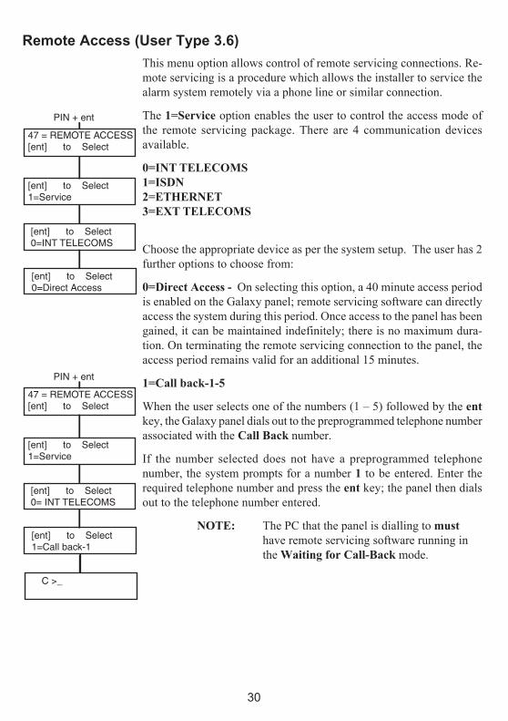
Remote Access (User Type 3.6)
This menu option allows control of remote servicing connections. Re-mote servicing is a procedure which allows the installer to service thealarm system remotely via a phone line or similar connection.
The 1=Service option enables the user to control the access mode ofthe remote servicing package. There are 4 communication devicesavailable.
0=INT TELECOMS1=ISDN2=ETHERNET3=EXT TELECOMS
Choose the appropriate device as per the system setup. The user has 2further options to choose from:
0=Direct Access - On selecting this option, a 40 minute access periodis enabled on the Galaxy panel; remote servicing software can directlyaccess the system during this period. Once access to the panel has beengained, it can be maintained indefinitely; there is no maximum dura-tion. On terminating the remote servicing connection to the panel, theaccess period remains valid for an additional 15 minutes.
1=Call back-1-5
When the user selects one of the numbers (1 – 5) followed by the entkey, the Galaxy panel dials out to the preprogrammed telephone numberassociated with the Call Back number.
If the number selected does not have a preprogrammed telephonenumber, the system prompts for a number 1 to be entered. Enter therequired telephone number and press the ent key; the panel then dialsout to the telephone number entered.
NOTE: The PC that the panel is dialling to musthave remote servicing software running inthe Waiting for Call-Back mode.
[ent] to Select1=Service
PIN + ent
47 = REMOTE ACCESS[ent] to Select
[ent] to Select0=INT TELECOMS
[ent] to Select0=Direct Access
[ent] to Select1=Service
PIN + ent
47 = REMOTE ACCESS[ent] to Select
[ent] to Select0= INT TELECOMS
[ent] to Select1=Call back-1
C >_

31
Authorisation Access (User Type 3.6)
This option allows access to be authorised to managers in order to add/delete/change all user codes. This option can only be enabled by theauthorisation code (54321 by default).

32
AVOIDING FALSE ALARMSFalse alarms are inconvenient and may be costly. Police can withhold response from consistentoffenders.
Here are nine points to help avoid false alarms.
1. Be sure you fully understand how to operate the alarm system. In your absence someonethoroughly instructed, should be available to operate the system.
2. Before leaving the premises ensure that all doors and windows are securely closed.
3. Where passive infra red or movement detectors are installed make sure the areas are keptfree from all animals or birds. Particular attention should be paid to swinging signs,fluorescent lights, Christmas decorations, electric fans, heating or ventilating systems.These should be switched off if possible
4. Always follow the exit/entry route procedure agreed with your alarm installer.
5. Treat the alarm components with care to ensure they are not damaged.
6. Consult your alarm installer about changes to your building and its contents if you thinkthey may affect the alarm system or its performance.
7. Always report alarm activation to your alarm installer. If necessary, an engineer will besent to check the system.
8. If opening or closing times are monitored by a central station be sure you notify them ofany variations from the agreed times or password.
9. The system should be fitted with a stand-by battery (not included) which will operate thesystem for a limited period in the event of a mains failure. Please ensure that the mains isrestored as quickly as possible so that the stand-by battery can be recharged.

33
ZONE REFERENCE TABLESenoZ noitcnuF noitpircseD emihC timO traP
1001
2001
3001
4001
5001
6001
7001
8001
1101
2101
3101
4101
5101
6101
7101
8101
OIR enoZ noitcnuF noitpircseD emihC timO traP
1
2
3
4
5
6
7
8
OIR enoZ noitcnuF noitpircseD emihC timO traP
1
2
3
4
5
6
7
8

34
ALARM AND HELP MESSAGES
Alarm In ProgressThe system is currently in alarm condition and must be cancelled by a valid PIN or
keyswitch operation.
Pa Reset RequiredAfter a PA (Personal Attack) zone has been activated, the system has to be reset by ahigh level code (such as a manager or engineer depending on the reset level setting).
Manager Reset Required
Following an alarm activation, the system requires to be reset by a manager level code.
This message is displayed when a tamper alarm occurs.
Engineer Reset RequiredThe system has been programmed for engineer reset following an alarm activation. Theengineer must be called to reset the system before the user can set the alarm.Tamper
alarms usually require an engineer to visit the site to check all modules on the system.
No EntriesThis message appears if a user attempts to view or inspect the log and there is nothing inthe log to be viewed or when the omit option is selected and there are no omittablezones on the system.
Invalid SelectionThe option selected or value entered is illegal or out of range.
Invalid CodeThe code entered is not a valid code registered in the system memory.
Option Not AvailableThis option is provided by the engineer, where it is specifically required. Attempting to
select an option when it has not been provided results in the display of
Technistore ResetCall the Alarm Monitoring Station and quote the five digit number displayed. Enter thenumber quoted by the monitoring station to reset the system.
No Modules AddedWhen exiting Engineer Mode the panel does not detect the change in the number of
modules. Press esc to continue.
NO MODULE ADDEDESC TO CONTINUE
ALARM INPROGRESS
PARESET REQUIRED
CALL MANAGERRESET REQUIRED
CALL ENGINEERRESET REQUIRED
NO ENTRIES
INVALIDOPTION
Invalid code
Option notavailable
CALL ALARM CO.QUOTE CODE XXXXX

35
INSTALLER DETAILS
Name: -----------------------------------------------------------------------------------
Address: ---------------------------------------------------------------------------------
-------------------------------------------------------------------------------------------
-------------------------------------------------------------------------------------------
-------------------------------------------------------------------------------------------
Telephone: ------------------------------------------------------------------------------
Office Hours: ---------------------------------------------------------------------------
Other Times: ---------------------------------------------------------------------------
Account No.: ---------------------------------------------------------------------------

36IU1-0033 Rev 1 © Copyright Honeywell Security