galaxy fixation system upper extremities · with indications for use in trauma and orthopaedics. it...
TRANSCRIPT

OPERATIVE TECHNIQUE
Galaxy Fixation SystemUpper Extremities
Key contributors:M.A. Aita, MD M. Assom, MDV. Caiaffa, MDT. Gausepohl, MDC. Grim, MD

1 INTRODUCTION
1 INDICATIONS
2 FEATURES AND BENEFITS
9 EQUIPMENT REQUIRED
12 HUMERAL APPLICATION12 APPROACH TO THE HUMERUS
17 MULTISCREW CLAMP
18 SHOULDER APPLICATION18 OPERATIVE TECHNIQUE25 POST-OPERATIVE MANAGEMENT
26 ELBOW APPLICATION27 OPERATIVE TECHNIQUE33 ELBOW MOVEMENT
34 ELBOW DISTRACTOR UNITPOST-TRAUMATIC STIFFNESS
40 WRIST APPLICATION40 APPROACH TO THE WRIST41 INTRA-ARTICULAR APPLICATION49 CONTROLLED RANGE OF MOVEMENT50 COMPRESSION-DISTRACTION52 EXTRA-ARTICULAR APPLICATION
56 UPPER LIMB APPLICATIONS
58 MRI INFORMATION
OPERATIVE TECHNIQUE 1
INDICATIONS
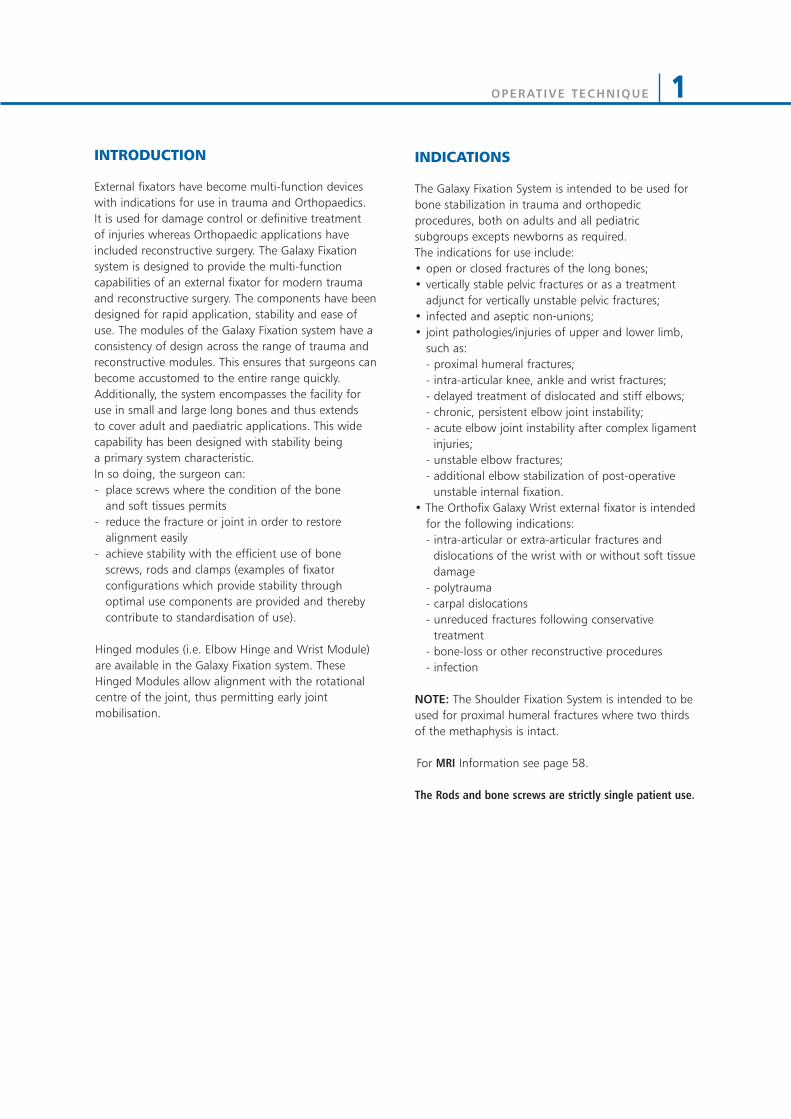
The Galaxy Fixation System is intended to be used forbone stabilization in trauma and orthopedicprocedures, both on adults and all pediatricsubgroups excepts newborns as required.The indications for use include:• open or closed fractures of the long bones;• vertically stable pelvic fractures or as a treatment
adjunct for vertically unstable pelvic fractures;• infected and aseptic non‐unions;• joint pathologies/injuries of upper and lower limb,
such as:- proximal humeral fractures;- intra-articular knee, ankle and wrist fractures;- delayed treatment of dislocated and stiff elbows;- chronic, persistent elbow joint instability;- acute elbow joint instability after complex ligament
injuries;- unstable elbow fractures;- additional elbow stabilization of post-operative
unstable internal fixation.• The Orthofix Galaxy Wrist external fixator is intended
for the following indications:- intra-articular or extra-articular fractures and
dislocations of the wrist with or without soft tissuedamage
- polytrauma- carpal dislocations- unreduced fractures following conservative
treatment- bone-loss or other reconstructive procedures- infection
NOTE: The Shoulder Fixation System is intended to beused for proximal humeral fractures where two thirdsof the methaphysis is intact.
For MRI Information see page 58.
The Rods and bone screws are strictly single patient use.
INTRODUCTION
External fixators have become multi-function deviceswith indications for use in trauma and Orthopaedics. It is used for damage control or definitive treatmentof injuries whereas Orthopaedic applications haveincluded reconstructive surgery. The Galaxy Fixationsystem is designed to provide the multi-functioncapabilities of an external fixator for modern traumaand reconstructive surgery. The components have beendesigned for rapid application, stability and ease ofuse. The modules of the Galaxy Fixation system have aconsistency of design across the range of trauma andreconstructive modules. This ensures that surgeons canbecome accustomed to the entire range quickly.Additionally, the system encompasses the facility foruse in small and large long bones and thus extends to cover adult and paediatric applications. This widecapability has been designed with stability being a primary system characteristic.In so doing, the surgeon can:- place screws where the condition of the bone
and soft tissues permits- reduce the fracture or joint in order to restore
alignment easily- achieve stability with the efficient use of bone
screws, rods and clamps (examples of fixatorconfigurations which provide stability throughoptimal use components are provided and therebycontribute to standardisation of use).
Hinged modules (i.e. Elbow Hinge and Wrist Module)are available in the Galaxy Fixation system. TheseHinged Modules allow alignment with the rotationalcentre of the joint, thus permitting early jointmobilisation.

OPERATIVE TECHNIQUE2
FEATURES AND BENEFITS
RodsStrong radiolucent rods in three different diameters(12mm for Lower Limb, 9 and 6mm for Upper Limb)and various lengths.
Code Description932100 Rod 100mm long932150 Rod 150mm long932200 Rod 200mm long932250 Rod 250mm long932300 Rod 300mm long932350 Rod 350mm long932400 Rod 400mm long
Rods Diam. 12mm MR
Rods Diam. 9mm MR
Rods Diam. 6mm MR
XCaliber Bone Screws Shaft Ø 6mm- Thread Ø 6.0-5.6mm
Code Total L Thread L912630 260 30912640 260 40912650 260 50912660 260 60912670 260 70912680 260 80912690 260 90
Code Total L Thread L911530 150 30911540 150 40911550 150 50911560 150 60911570 150 70911580 150 80911590 150 90
• Drill bit Ø 4.8mm when the bone is hard• Drill bit Ø 3.2mm in poor quality bone or in the metaphyseal region
Bone Screws Shaft Ø 6mm - Thread Ø 4.5-3.5mm
Code Total L Thread L10190 70 2010191 80 2010108 80 3010135 100 2010136 100 30
Code Total L Thread L10105 100 4010137 120 2010138 120 3010106 120 40
• Drill bit Ø 3.2mm
Code Description936060 Rod 60mm long936080 Rod 80mm long936100 Rod 100mm long936120 Rod 120mm long936140 Rod 140mm long936160 Rod 160mm long936180 Rod 180mm long936200 Rod 200mm long
Code Description939100 Rod 100mm long939150 Rod 150mm long939200 Rod 200mm long939250 Rod 250mm long939300 Rod 300mm long
Semi-Circular Rods Diam. 9mm 939010 Semi-Circular Rod small 115mm long939020 Semi-Circular Rod medium 140mm long939030 Semi-Circular Rod large 165mm long
Rod Diam. 6mm
Code Description936010 6mm L Rod
Screws
Bone Screws Shaft Ø 4mm - Thread Ø 3.3-3.0mm
Code Total L Thread L35100 70 20
Code Total L Thread L35101 80 35
• Drill bit Ø 2.7mm
Self-drilling Bone Screws Shaft Ø 4mm - Thread Ø 3.3-3.0mm
Code Total L Thread L37100 60 2037102 100 30
Code Total L Thread L37101 70 30
Self-drilling Bone Screws Shaft Ø 3mm - Thread Ø 3.0-2.5mm
Code Total L Thread LM310 50 18M311 60 20M312 60 25M313 60 30M321 70 15
Code Total L Thread LM314 70 20M315 70 25M316 70 30M317 100 30
XCaliber CylindricalBone Screws Shaft Ø 4mm - Thread Ø 3.0mm
• Self-drilling
Code Total L Thread L948320 120 20948325 120 25948335 120 35
Code Total L Thread L947320 100 20947325 100 25
Galaxy Fixation System is compatible with all OrthofixBone Screws with shaft and thread diameters asindicated above. Please refer to the Orthofix ProductsCatalogue.
OPERATIVE TECHNIQUE 3
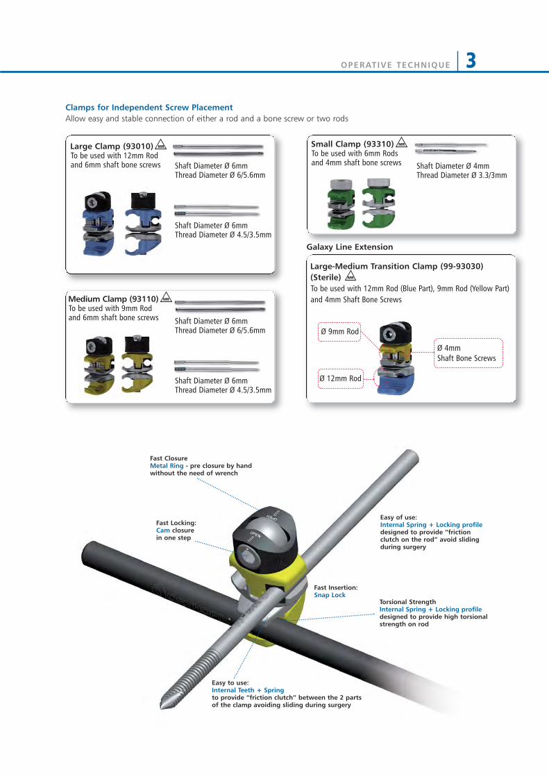
Shaft Diameter Ø 6mmThread Diameter Ø 4.5/3.5mm
Shaft Diameter Ø 4mmThread Diameter Ø 3.3/3mm
Shaft Diameter Ø 6mmThread Diameter Ø 6/5.6mm
Shaft Diameter Ø 6mmThread Diameter Ø 4.5/3.5mm
Shaft Diameter Ø 6mmThread Diameter Ø 6/5.6mm
Large-Medium Transition Clamp (99-93030)(Sterile) To be used with 12mm Rod (Blue Part), 9mm Rod (Yellow Part)and 4mm Shaft Bone Screws
MR
Ø 9mm Rod
Ø 12mm Rod
Ø 4mm Shaft Bone Screws
Galaxy Line Extension
Clamps for Independent Screw PlacementAllow easy and stable connection of either a rod and a bone screw or two rods
Large Clamp (93010)To be used with 12mm Rod and 6mm shaft bone screws
MR
Medium Clamp (93110)To be used with 9mm Rod and 6mm shaft bone screws
MR
Small Clamp (93310)To be used with 6mm Rods and 4mm shaft bone screws
MR
Fast Locking:Cam closure in one step
Easy of use:Internal Spring + Locking profiledesigned to provide “frictionclutch on the rod” avoid slidingduring surgery
Fast Closure Metal Ring - pre closure by handwithout the need of wrench
Fast Insertion:Snap Lock
Torsional StrengthInternal Spring + Locking profiledesigned to provide high torsionalstrength on rod
Easy to use:Internal Teeth + Spring to provide “friction clutch” between the 2 parts of the clamp avoiding sliding during surgery

OPERATIVE TECHNIQUE4
Galaxy Line Extension
Multiscrew Clamp (93020)
• To be used with 12mm Rod and 6mm shaft bonescrews.
• Allows parallel screw positioning either in a T- or astraight clamp configuration.
Note: the positions of the screw holes in themultiscrew clamp refer to the screw seats of theXCaliber fixator or the 1,3,5 screw seats of the LRSfixator T- or straight clamps.
MR
Fast Insertion:Snap Lock
Fast Locking:Cam closure inone step
Flexibility of use:Rotation up to +/- 35°
Fast Closure:Metal Ring - pre closure by handwithout the need of wrench
Stability:Internal Spring +Locking profiledesigned to provide high torsionalstrength on rod
Ø 9mm Rod
Ø 6mm ShaftBone Screws
Medium Multiscrew Clamp(99-93120) (Sterile) •To be used with 9mm Rod and
6mm Shaft Bone Screws. •Allows parallel screw positioning
(+/- 35°) in either a T-clamp orstraight clamp configuration.
Note: the positions of the screwholes in the medium screw clamprefer to the screw seats of the SmallBlue D.A.F. (31000) or the pediatricLRS system (series 55000)
MR
Small Multiscrew Clamp-Long (93320)To be used with 6mm Rods and 3 or 4mm shaft bone screws
MR
Small Multiscrew Clamp-Short (93330)To be used with 6mm Rods and 3 or 4mm shaft bonescrews
MR
Shaft Diameter Ø 4mmThread Diameter Ø 3.3-3.0mm
Shaft Diameter Ø 3mmThread Diameter Ø 3.0-2.5mm
Shaft Diameter Ø 4mmThread Diameter Ø 3.0mm
Shaft Diameter Ø 4mmThread Diameter Ø 3.3-3.0mm
Shaft Diameter Ø 3mmThread Diameter Ø 3.0-2.5mm
Shaft Diameter Ø 4mmThread Diameter Ø 3.0mm
-35° +35°
0°
Multiscrew Clamps

OPERATIVE TECHNIQUE 5
Clamps Closure
Start PositionDot on cam in line with OPENmarking on the base of the clamp
Pre-ClosureTurn the the knob fully by hand
Final ClosureTighten the cam with Wrench
1 2
3
1
Final ClosureTighten the cam with Wrench3
Pre-ClosureTurn the locking screwfully by hand
Final ClosureTighten the locking screw withWrench
1
2
Start PositionDot on cam in line with OPENmarking on metal ring
Pre-ClosureTurn the metalring fully by hand
2
OPERATIVE TECHNIQUE6
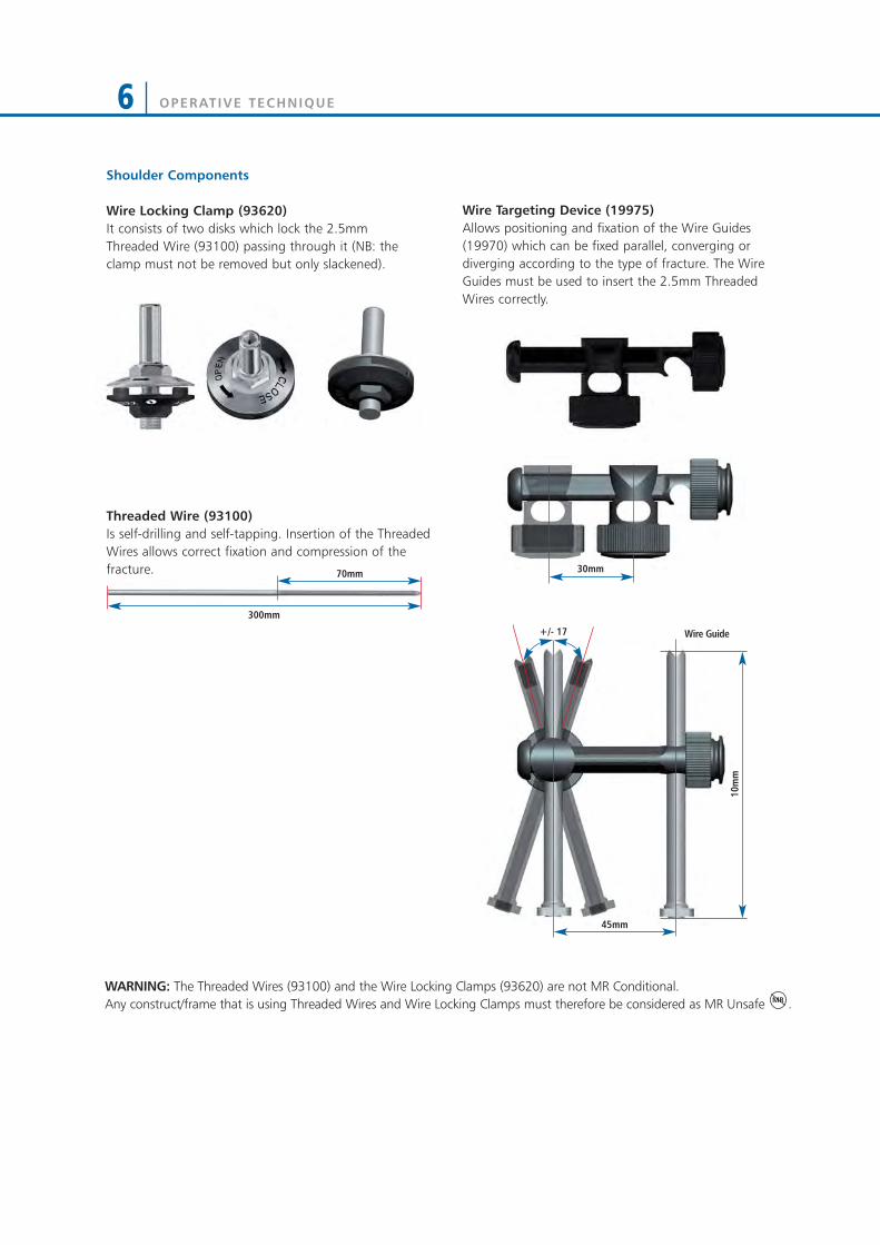
+/- 17
45mm
70mm 30mm
10m
m
Wire Guide
Shoulder Components
Wire Locking Clamp (93620) It consists of two disks which lock the 2.5mmThreaded Wire (93100) passing through it (NB: theclamp must not be removed but only slackened).
Wire Targeting Device (19975)Allows positioning and fixation of the Wire Guides(19970) which can be fixed parallel, converging ordiverging according to the type of fracture. The WireGuides must be used to insert the 2.5mm ThreadedWires correctly.
Threaded Wire (93100)Is self-drilling and self-tapping. Insertion of the ThreadedWires allows correct fixation and compression of thefracture.
300mm
WARNING: The Threaded Wires (93100) and the Wire Locking Clamps (93620) are not MR Conditional.Any construct/frame that is using Threaded Wires and Wire Locking Clamps must therefore be considered as MR Unsafe .MR

OPERATIVE TECHNIQUE 7
Elbow Components
Elbow Hinge (93410)• To be used with 12mm Rod for the humerus and
9mm Rod for the Ulna• Radiolucent hinge which allows easy location of the
centre of rotation of the elbow, flexion-extension(up to 175°) and micrometric distraction (15mm) ofthe joint
MR
Left/Right
Rods
Ulnar Distractor Clamp
Humeral Distractor Clamp
Elbow Distractor (932200 - 93431 - 93432)• To distract the joint intra-operatively in case of elbow
stiffness (see page 34)
Elbow Motion Unit (93420)• To be used with the Elbow Hinge for passive motion• Allows controlled, limited flexion/extention of the joint
Extension
Flexion
0°
0°
90°
85°
OPERATIVE TECHNIQUE8
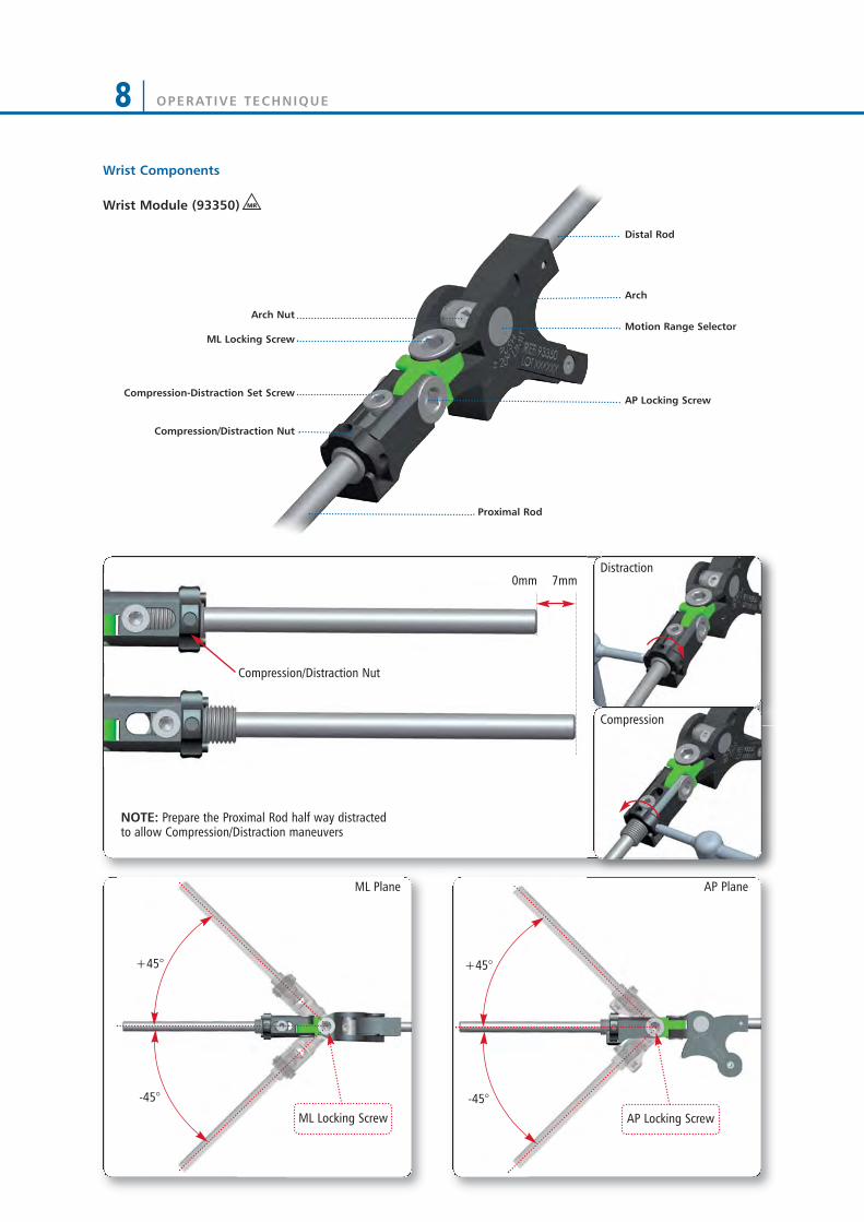
+45°
-45°
+45°
-45°
ML Plane AP Plane
ML Locking Screw AP Locking Screw
Arch
Motion Range Selector
AP Locking Screw
Proximal Rod
Distal Rod
ML Locking Screw
Arch Nut
Compression-Distraction Set Screw
Compression/Distraction Nut
Compression/Distraction Nut
7mm0mm
NOTE: Prepare the Proximal Rod half way distractedto allow Compression/Distraction maneuvers
Wrist Components
Wrist Module (93350) MR
Distraction
Compression

OPERATIVE TECHNIQUE 9
EQUIPMENT REQUIRED
INSTRUMENTS TRAY
Can accomodate:
RODS & CLAMPS TRAY*
Can accomodate:
Code Description19940 Multiscrew Clamp Guide11138 Drill Guide d 4.8mm11137 Screw Guide 80mm1-1100201 Drill Bit d 4.8x240mm Coated - Quick Connect11106 Drill Guide d 3.2mm11102 Screw Guide 60mm 1-1300301 Drill Bit d 3.2x140mm Coated - Quick Connect 19955 Trocar19960 Wrist Guide Template with Handle13530 Drill Guide d 2.7mm 1-1355001 Drill Bit d 2.7x127mm Coated - Quick Connect19965 Tapered Trocar M210 T Wrench 93150 Racheting T Handle93155 Screw Shaft Connection 30017 Allen Wrench 5mm 93017 Wrench 5mm Shaft Connection
Code DescriptionLower Tray93010 Large Clamp 93020 Multiscrew Clamp 932400 Rod d 12mm L 400mm 932350 Rod d 12mm L 350mm 932300 Rod d 12mm L 300mm 932250 Rod d 12mm L 250mm 932200 Rod d 12mm L 200mm 932150 Rod d 12mm L 150mm 932100 Rod d 12mm L 100mm 932030 Semi Circular Rod d 12mm large932020 Semi Circular Rod d 12mm medium 932010 Semi Circular Rod d 12mm smallUpper Tray93110 Medium Clamp 93310 Small Clamp 939300 Rod d 9mm L 300mm 939250 Rod d 9mm L 250mm 939200 Rod d 9mm L 200mm 939150 Rod d 9mm L 150mm 939100 Rod d 9mm L 100mm 936200 Rod d 6mm L 200mm 936180 Rod d 6mm L 180mm 936160 Rod d 6mm L 160mm 936140 Rod d 6mm L 140mm 936120 Rod d 6mm L 120mm 936100 Rod d 6mm L 100mm 936080 Rod d 6mm L 80mm 936060 Rod d 6mm L 60mm
* to order any of the Rods or Clamps, single-packaged and sterile, please add 99- prior to the part number, ex. 99-93010
OPERATIVE TECHNIQUE10
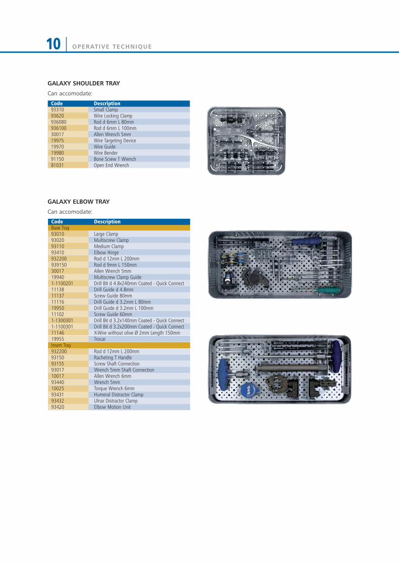
GALAXY ELBOW TRAY
Can accomodate:
GALAXY SHOULDER TRAY
Can accomodate:
Code Description93310 Small Clamp93620 Wire Locking Clamp 936080 Rod d 6mm L 80mm 936100 Rod d 6mm L 100mm30017 Allen Wrench 5mm 19975 Wire Targeting Device 19970 Wire Guide 19980 Wire Bender91150 Bone Screw T Wrench81031 Open End Wrench
Code DescriptionBase Tray93010 Large Clamp 93020 Multiscrew Clamp 93110 Medium Clamp 93410 Elbow Hinge 932200 Rod d 12mm L 200mm 939150 Rod d 9mm L 150mm 30017 Allen Wrench 5mm 19940 Multiscrew Clamp Guide 1-1100201 Drill Bit d 4.8x240mm Coated - Quick Connect 11138 Drill Guide d 4.8mm 11137 Screw Guide 80mm 11116 Drill Guide d 3.2mm L 80mm 19950 Drill Guide d 3.2mm L 100mm 11102 Screw Guide 60mm 1-1300301 Drill Bit d 3.2x140mm Coated - Quick Connect1-1100301 Drill Bit d 3.2x200mm Coated - Quick Connect11146 X-Wire without olive Ø 2mm Length 150mm19955 TrocarInsert Tray932200 Rod d 12mm L 200mm 93150 Racheting T Handle 93155 Screw Shaft Connection 93017 Wrench 5mm Shaft Connection 10017 Allen Wrench 6mm 93440 Wrench 5mm 10025 Torque Wrench 6mm93431 Humeral Distractor Clamp 93432 Ulnar Distractor Clamp 93420 Elbow Motion Unit

OPERATIVE TECHNIQUE 11
TRAY CONFIGURATIONS
GALAXY WRIST TRAY
Can accomodate:
Code Description1x93999 Galaxy Wrist Tray empty2x93320 Small Multiscrew Clamp-Long2x93330 Small Multiscrew Clamp-Short6x93310 Small Clamp1x93350 Wrist Module1x936200 Rod d 6mm L 200mm2x936100 Rod d 6mm L 100mm1x936080 Rod d 6mm L 80mm1x936120 Rod d 6mm L 120mm3x13715 Xwire d1,5x150mm1x936010 6mm L Rod 2x19995 Screw Guide2x13530 Drill Guide d 2.7mm 1x91017 Allen Wrench 2x1-1355001 Drill Bit d 2.7mm1x19965 Tapered Trocar1xM210 T Wrench1x93160 Screw T Wrench QC1x93175 T Wrench 4mm Shaft
GALAXY WRIST STERILE KIT (99-93601)
Consisting of:
Code Description2x93330 Small multiscrew clamp-SHORT1x93350 Wrist Module2x19995 Screw Guide2x13530 Drill guide Ø2.7mm 1x91017 Allen Wrench4x947320 Self Drilling XCaliber Cylindrical Screw
Shaft Ø4mm Thread 3mm L 100/20 QC2x1-1355001 Drill Bit Ø2,7mm1x93160 Screw T Wrench QC3x13715 Kwire Ø1,5x150mm
93991C Galaxy Upper + Lower Complete93992C Galaxy Instruments Complete93993C Galaxy Lower + Instruments Complete93994C Galaxy Upper + Instruments Complete93995C Galaxy Upper Complete93996C Galaxy Lower Complete93998C Galaxy Shoulder Complete93997C Galaxy Elbow Complete93999C Galaxy Wrist Complete

HUMERAL APPLICATION
APPROACH TO THE HUMERUSWhen dealing with the humerus, consideration shouldbe given to the radial, axillary, musculocutaneous,ulnar and median nerves and brachial artery and vein.Proximally, screws should be inserted distal to the levelof the axillary nerve. They can be placed from a lateralapproach or ventro-lateral direction.
The middle segment of the humerus (shaded in red)should be avoided as the radial nerve has a variablecourse in this area.
Distally, a screw inserted from the lateral side betweenthe triceps and brachioradialis muscles will avoid the radial nerve as long as it is just proximal to theupper border of the olecranon fossa.A more proximal screw can be inserted just medial to the lateral border of biceps, thereby avoiding the terminal branch of the musculocutaneous nerve.An alternative is a half screw inserted from the dorsal surface.
60°
30°
25°
25°
20°
OPERATIVE TECHNIQUE12

OPERATIVE TECHNIQUE 13
Screw InsertionScrew positions should be planned with regard to zone of injury; often this may extend beyond the fracture linesvisible on X-ray. Further thought into possible futuresurgeries, including plastic surgical and internal fixationprocedures, should be given. X-rays of the fracture in twoplanes should be available. In general, screws should beplaced anterolaterally in the femur; anteriorly (1cm medialto the tibial crest in an anteroposterior direction) in thetibia; laterally in the proximal third of humerus andposterolaterally in the distal third of the humerus. Screwsshould be positioned for maximum mechanical stability ineach bone segment, with bicortical purchase by the screwthreads and with each pin as far apart in each segment asthe fracture lines and neighbouring joints allow.
Insert two screws into each main fragment free-handusing the following technique: 1) Make a 15mm incision through skin and deepfascia. Use blunt dissection to reach the underlyingbone (Fig. 1).
2) Insert a screw guide perpendicular to thelongitudinal axis of the bone. Use a trocar to locatethe midline by palpation (Fig. 2).
3) Keeping the screw guide in contact with the cortexby gentle pressure, withdraw the trocar, and tap thescrew guide lightly to anchor the pronged end againstbone (Fig. 3).
Fig. 1
Fig. 2
Fig. 3
OPERATIVE TECHNIQUE14
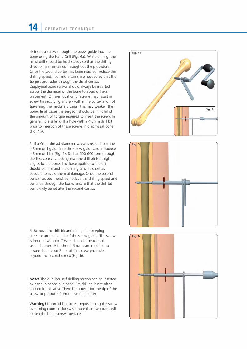
Fig. 4a4) Insert a screw through the screw guide into thebone using the Hand Drill (Fig. 4a). While drilling, thehand drill should be held steady so that the drillingdirection is maintained throughout the procedure.Once the second cortex has been reached, reduce thedrilling speed; four more turns are needed so that thetip just protrudes through the distal cortex.Diaphyseal bone screws should always be insertedacross the diameter of the bone to avoid off axisplacement. Off axis location of screws may result inscrew threads lying entirely within the cortex and nottraversing the medullary canal; this may weaken thebone. In all cases the surgeon should be mindful ofthe amount of torque required to insert the screw. Ingeneral, it is safer drill a hole with a 4.8mm drill bitprior to insertion of these screws in diaphyseal bone(Fig. 4b).
5) If a 6mm thread diameter screw is used, insert the4.8mm drill guide into the screw guide and introduce4.8mm drill bit (Fig. 5). Drill at 500-600 rpm throughthe first cortex, checking that the drill bit is at rightangles to the bone. The force applied to the drillshould be firm and the drilling time as short aspossible to avoid thermal damage. Once the secondcortex has been reached, reduce the drilling speed andcontinue through the bone. Ensure that the drill bitcompletely penetrates the second cortex.
6) Remove the drill bit and drill guide, keepingpressure on the handle of the screw guide. The screwis inserted with the T-Wrench until it reaches thesecond cortex. A further 4-6 turns are required toensure that about 2mm of the screw protrudesbeyond the second cortex (Fig. 6).
Note: The XCaliber self-drilling screws can be insertedby hand in cancellous bone. Pre-drilling is not oftenneeded in this area. There is no need for the tip of thescrew to protrude from the second cortex.
Warning! If thread is tapered, repositioning the screwby turning counter-clockwise more than two turns willloosen the bone-screw interface.
Fig. 5
Fig. 6
Fig. 4b

OPERATIVE TECHNIQUE 15
XCaliber bone screw designThe screws have a pointed tip and flute which allowthem to be inserted as self-drilling implants incancellous bone without the need for pre-drilling.Direct insertion with a hand drill is advised in mostsituations, irrespective of whether uncoated or HAcoated screws are used. However, when insertion ofthese self-drilling screws is performed in diaphysealbone, pre-drilling is recommended; use a 4.8mm drillbit through a drill guide when the bone is hard. If thebone quality is poor or, as in the metaphyseal region,where the cortex is thin, a 3.2mm drill bit should beused.
XCaliber bone screws should never be inserted with apower tool. This may result in high temperatures andcell necrosis from too high insertion speeds. Screwinsertion, whether or not pre-drilling has beenperformed, should always be with the XCaliber HandDrill (91120) or Rachet T Handle + Screw ShaftConnection (93150 + 93155). The screws have around shank which is gripped securely by the XCaliberT-handle or Hand Drill. It is important that moderateforce is applied initially for the screw to engage andgain entry into the first cortex.
(91120)
(93150)
(93155)
OPERATIVE TECHNIQUE16
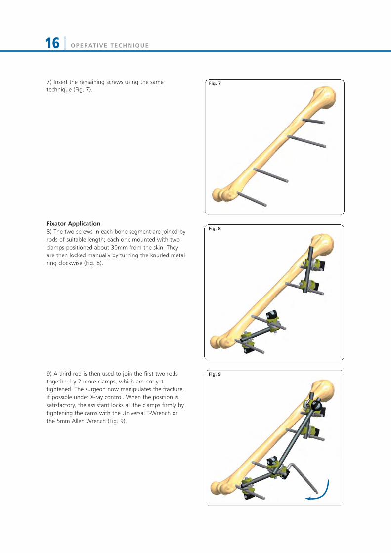
7) Insert the remaining screws using the sametechnique (Fig. 7).
Fixator Application8) The two screws in each bone segment are joined byrods of suitable length; each one mounted with twoclamps positioned about 30mm from the skin. Theyare then locked manually by turning the knurled metalring clockwise (Fig. 8).
9) A third rod is then used to join the first two rodstogether by 2 more clamps, which are not yettightened. The surgeon now manipulates the fracture,if possible under X-ray control. When the position issatisfactory, the assistant locks all the clamps firmly bytightening the cams with the Universal T-Wrench orthe 5mm Allen Wrench (Fig. 9).
Fig. 7
Fig. 8
Fig. 9
OPERATIVE TECHNIQUE 17
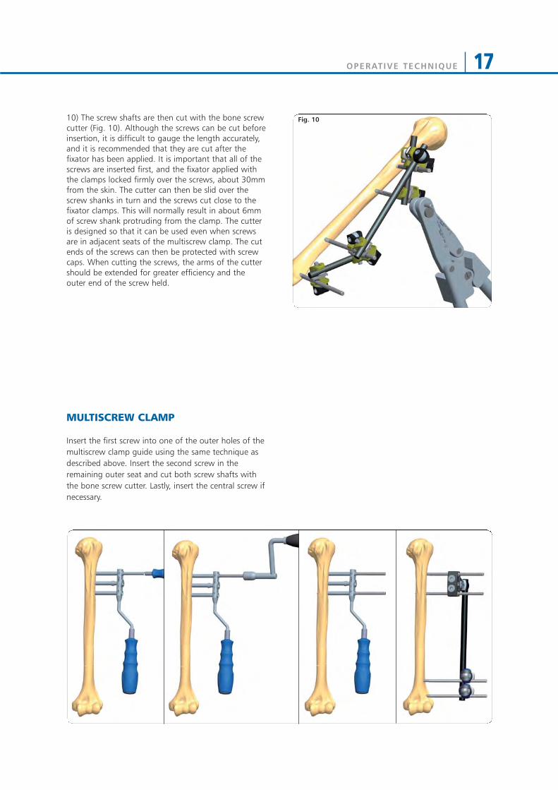
10) The screw shafts are then cut with the bone screwcutter (Fig. 10). Although the screws can be cut beforeinsertion, it is difficult to gauge the length accurately,and it is recommended that they are cut after thefixator has been applied. It is important that all of thescrews are inserted first, and the fixator applied withthe clamps locked firmly over the screws, about 30mmfrom the skin. The cutter can then be slid over thescrew shanks in turn and the screws cut close to thefixator clamps. This will normally result in about 6mmof screw shank protruding from the clamp. The cutteris designed so that it can be used even when screwsare in adjacent seats of the multiscrew clamp. The cutends of the screws can then be protected with screwcaps. When cutting the screws, the arms of the cuttershould be extended for greater efficiency and theouter end of the screw held.
MULTISCREW CLAMP
Insert the first screw into one of the outer holes of themultiscrew clamp guide using the same technique asdescribed above. Insert the second screw in theremaining outer seat and cut both screw shafts withthe bone screw cutter. Lastly, insert the central screw ifnecessary.
Fig. 10
OPERATIVE TECHNIQUE18
SHOULDER APPLICATION
OPERATIVE TECHNIQUE
Positioning the patient in the operating room
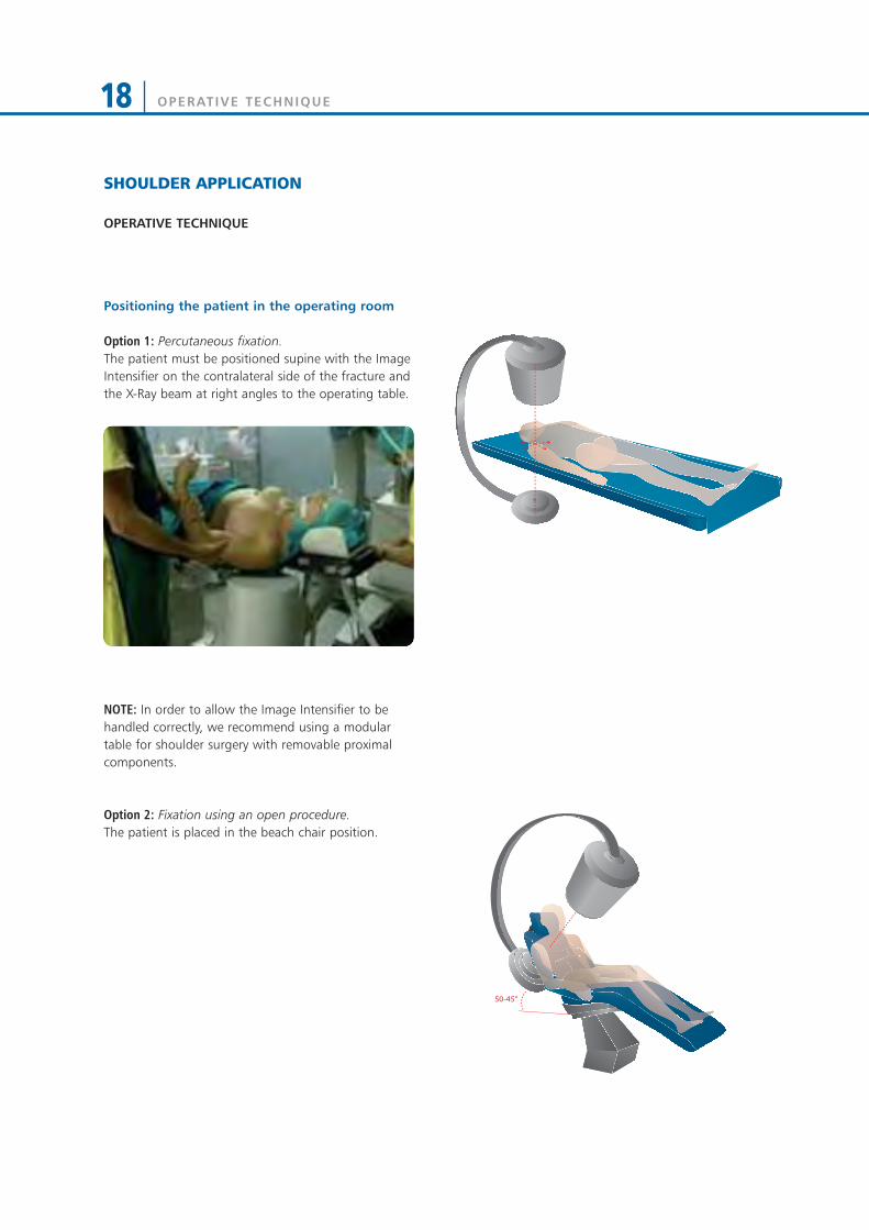
Option 1: Percutaneous fixation.The patient must be positioned supine with the ImageIntensifier on the contralateral side of the fracture andthe X-Ray beam at right angles to the operating table.
NOTE: In order to allow the Image Intensifier to behandled correctly, we recommend using a modulartable for shoulder surgery with removable proximalcomponents.
Option 2: Fixation using an open procedure. The patient is placed in the beach chair position.
50-45°

OPERATIVE TECHNIQUE 19
Assess the integrity of the external distal metaphysealarea (external 2/3 of the bone circumference),representing the entry point of the osteosynthesismeans.
NOTE: a bone block or an excessively distal fracturelevel can contraindicate a percutaneous procedure, forboth the technically difficult wire positioning and thefinal stability of implant.Alternatively, an open procedure must be performed,which facilitates the entry point of the wire in thecortex.
Anterior, posterior and trans-thoracic CT-scans.
X-rays must always be carried out in AP, trans-thoracicor outlet view, and when possible, axillary view todefine the configuration, position and size of thevarious bone fragments. A CT scan of the humeralhead should also be performed.
Anterior, posterior and trans-thoracic X-rays.
OPERATIVE TECHNIQUE20
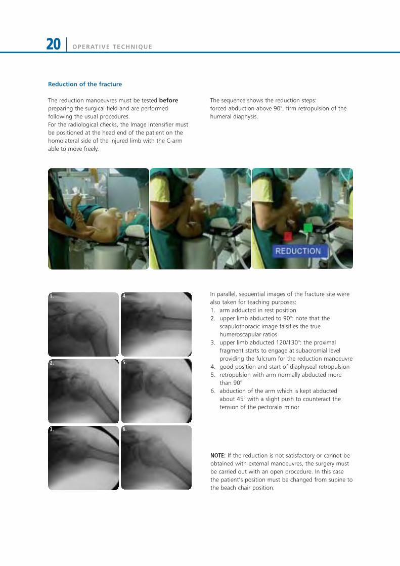
The sequence shows the reduction steps: forced abduction above 90°, firm retropulsion of thehumeral diaphysis.
In parallel, sequential images of the fracture site werealso taken for teaching purposes:1. arm adducted in rest position2. upper limb abducted to 90°: note that the
scapulothoracic image falsifies the truehumeroscapular ratios
3. upper limb abducted 120/130°: the proximalfragment starts to engage at subacromial levelproviding the fulcrum for the reduction manoeuvre
4. good position and start of diaphyseal retropulsion5. retropulsion with arm normally abducted more
than 90°6. abduction of the arm which is kept abducted
about 45° with a slight push to counteract thetension of the pectoralis minor
NOTE: If the reduction is not satisfactory or cannot beobtained with external manoeuvres, the surgery mustbe carried out with an open procedure. In this casethe patient’s position must be changed from supine tothe beach chair position.
1.
2.
3.
4.
5.
6.
Reduction of the fracture
The reduction manoeuvres must be tested beforepreparing the surgical field and are performedfollowing the usual procedures.For the radiological checks, the Image Intensifier mustbe positioned at the head end of the patient on thehomolateral side of the injured limb with the C-armable to move freely.

OPERATIVE TECHNIQUE 21
Preparation of the surgical field
The area of the acromioclavicular joint must be visible:this is important for the percutaneous insertion of thewires. A poor surgical field will result in an excessivelylow insertion point. The upper limb must not impedethe surgeon’s movement.
Positioning of the percutaneous wires
The system has proved to achieve good stabilityindependently from the order in which the wires havebeen positioned.However, positioning of the first 2/3 wires dependsupon the position in which the upper limb is placed inorder to maintain reduction.
NOTE: It is extremely important that in maintaining thereduction the assistant keeps the injured arm parallelto the ground: in this position the humeral head isnaturally offset more posteriorly than the diaphysealplane, which corresponds to the horizontal referenceplane. This will help to insert the first wire in the frontplane, with an inclination of about 20° to theground/humeral diaphysis, in order to target the apexof the humeral head. The entry point will be about 4/5cm proximal to the deltopectoral sulcus anterior tothe line parallel to the humeral diaphysis which startsat the tip of the V insertion of the deltoid. Thecircumflex nerve anterior to this line is frayed andworking anteriorly prevents iatrogenic neurologicalinjuries. The diaphyseal cortical entry point must be asclose as possible to the surgical neck fracture site: thecondition of the area should have been carefullyassessed pre-operatively with CT scan.
In 3 or 4 part fractures or fractures which show acertain instability after reduction, 2 wires withproximo-distal direction must be added to stabilise thegreater tubercle to the head and to the humeraldiaphysis as shown in the figure, both in case theprocedure is carried out percutaneously or with anopen access.This operation requires further assembly to connectthe distal osteosynthesis with the proximalosteosynthesis.

OPERATIVE TECHNIQUE22
Inserting the wires with the aid of the WireTargeting Device:
1) Insert the wires at slow speed.Position the first wire using the soft tissues protectiveguide (Fig. 1).
The correct position of the wires must be confirmed byX-rays.
2) Lock the Wire Targeting Device to the Wire Guide,turning the external knob in a clockwise direction (Fig. 2).
3) Insert the second Wire Guide into the WireTargeting Device, place it in the most suitable positionfor reducing the fracture and lock it with the externalknob (Fig. 3).
4) Insert the second wire into this Wire Guide. Thewires have been marked to verify the correct insertiondepth, reducing the use of image intensification (Fig. 4).
Fig. 1
Fig. 2
Fig. 3
Fig. 4
120m
m45
mm

OPERATIVE TECHNIQUE 23
5) Repeat the procedure for the remaining wires. The implant must have at least 4 wires which do notoverlap (Fig. 5a e Fig. 5b). If the reduction is notsatisfactory, pull back the wires until the fracture isreleased, without removing them completely from thediaphysis. Improve the reduction with externalmanoeuvres and insert the wires back until grippingthe humeral head fragment.
NOTE: In 3-part fractures with detachment of thegreater tubercle, 1 or 2 extra wires should be appliedto stabilise the fragment.The most successful insertion point is at the level ofthe greater tubercle-head junction.The direction can be targeted either towards themedial diaphyseal area or towards the humeral headitself.A further clamp and rod will be necessary to stabilisethe wires with proximal-distal direction.
6) Once reduction has been achieved, bend the wires(93100) at about 90° with the Wire Bender (19980),leaving a distance of about 3cm from the skin: thiswill facilitate medication and removal at the end oftreatment (Fig. 6a). The wires are oriented in pairs of 2 so that they runapproximately parallel along the same plane. Theflexibility of the system and the small rotationalmovements still possible with a single wire permit theappropriate wire direction (Fig. 6b).
Stabilisation of the wires
7) Holding the Wire Locking Clamp (93620) in placewith the Open End Wrench 10mm (81031), tightenthe upper disk of the clamp using the Universal T-Wrench (91150) (Fig. 7).
Fig. 6a Fig. 6b
Fig. 7
Fig. 5a Fig. 5b

OPERATIVE TECHNIQUE24
8) Repeat the same procedure for the remaining pairsof wires. Cut the wire distally close to the Wire LockingClamp (Fig. 8).
9) Connect each clamp with a Galaxy Small Clamp(93310) and then connect them with a 6mm diameterrod (Fig. 9). Test the stability of the fixation underimage intensification.
10) Cover the wires with the Wire Cover (80200) (Fig. 10).
Fig. 8
Fig. 9
Fig. 10
OPERATIVE TECHNIQUE 25
POST-OPERATIVE MANAGEMENT
The wires are kept in place for an average of 6 weekswith the arm supported in a sling, but the period maybe extended up to 8 weeks depending upon thefracture type.During the first 15 days the patient must keep theshoulder strictly at rest: the sling may be removed forpersonal hygiene, and mobilisation of the elbow andswinging movements may be allowed several times aday. Starting from the third week, passive motion can becommenced with a range of freedom proportional tothe severity of the fracture. Passive mobilisation willcontinue until removal of the wires.
Removal of the wires
The wires guarantee good mechanical stability untilthe end of treatment. Cut the 2.5mm Threaded Wire leaving enough spaceto connect the reverse drill to it. Anaesthesia may notbe necessary.The procedure can be carried out in the Out-PatientClinic.

OPERATIVE TECHNIQUE26
ELBOW APPLICATION
Patient Positioninga) Positioning of the patient: the patient is in a supineposition. The injured arm is positioned on the table sothat radiographs of the humerus can be performed. A tourniquet generally should not be applied. If concomitant injuries make open osteosynthesisnecessary (radial head fracture, condyle dislocation,etc.), appropriate bleeding stoppage will be necessaryif the fixator is to be applied in the same procedure.As an alternative, osteosynthesis can be firstperformed separately in a bloodless field. Afterrepeated disinfection and draping, the fixator canthen be applied. In this case, it is important to ensureadequate bleeding stoppage to avoid hemorrhagein the operative field after removing the tourniquet.A single-step approach with minimal tissuetrauma and use of bleeding stoppage is preferred.
Hint: It can sometimes be useful to raise theshoulder by placing a rolled-up towel below it.
b) Preparation of the patient: when performingdisinfection, the entire upper limb and shoulder arewashed. The arm can be held by the hand during thedisinfection process. For this, the patient’s hand iswrapped in an adhesive drape. As an alternative, thehand can also be disinfected. The surgeon sits at thepatient’s head with the assistant on the other side ofthe patient. The Image Intensifier is moved in from theside. It is important that the surgeon has adequateaccess to the elbow when the Image Intensifier is inplace.
c) Use of Image Intensifier: the left figure shows agood position for the monitor. During surgery, thesurgeon and assistant should have an unobstructedview of the monitor.
SURGEON
IMAGEINTENSIFIER
C-ARM
ASSISTANT

OPERATIVE TECHNIQUE 27
OPERATIVE TECHNIQUE
1) Expose the lateral aspect of the Humerus by bluntdissection in order to avoid damage to the radialnerve, taking into account that the first screw has tobe inserted at the proximal level, placed notcompletely lateral but 10-15 degrees anterior. Use the multiscrew clamp as a template to insertscrews perpendicular to the longitudinal axis of thebone. Insert the screw guides and position the trocar(19955), into one of the outer holes of the multiscrewclamp. Use the trocar to locate the midline bypalpation (Fig. 1).
NOTE: The middle segment of the Humerus should beavoided as the radial nerve has a variable course inthis area.
2) Keeping the screw guide in contact with the cortexby gentle pressure, withdraw the trocar, and tap thescrew guide lightly to anchor its distal end. Make surethat there are no soft tissues between the bone andthe screw guide. Insert the 4.8mm drill guide (11102)into the screw guide, and drill with a 4.8mm drill bit(11001). Use a sharp drill and make sure that the drillbit is at right angles to the bone, the force is appliedto the drill is firm and the drilling time as short aspossible to avoid thermal damage (Fig. 2). Once thesecond cortex has been reached, reduce the drillingspeed and continue through the bone. Ensure that thedrill bit completely penetrates the second cortex.
3) Remove the drill bit and drill guide, keepingpressure on the handle of the screw guide. Insert ascrew through the screw guide into the bone usingthe T-wrench (Fig. 3) or hand drill. While drilling, the hand drill should be held steadilyso that the drilling direction is maintained throughoutthe procedure. The screw should completely engagethe second cortex for bicortical purchase. Use thesame technique for the second screw.
Fig. 1
Fig. 2
Fig. 3
OPERATIVE TECHNIQUE28
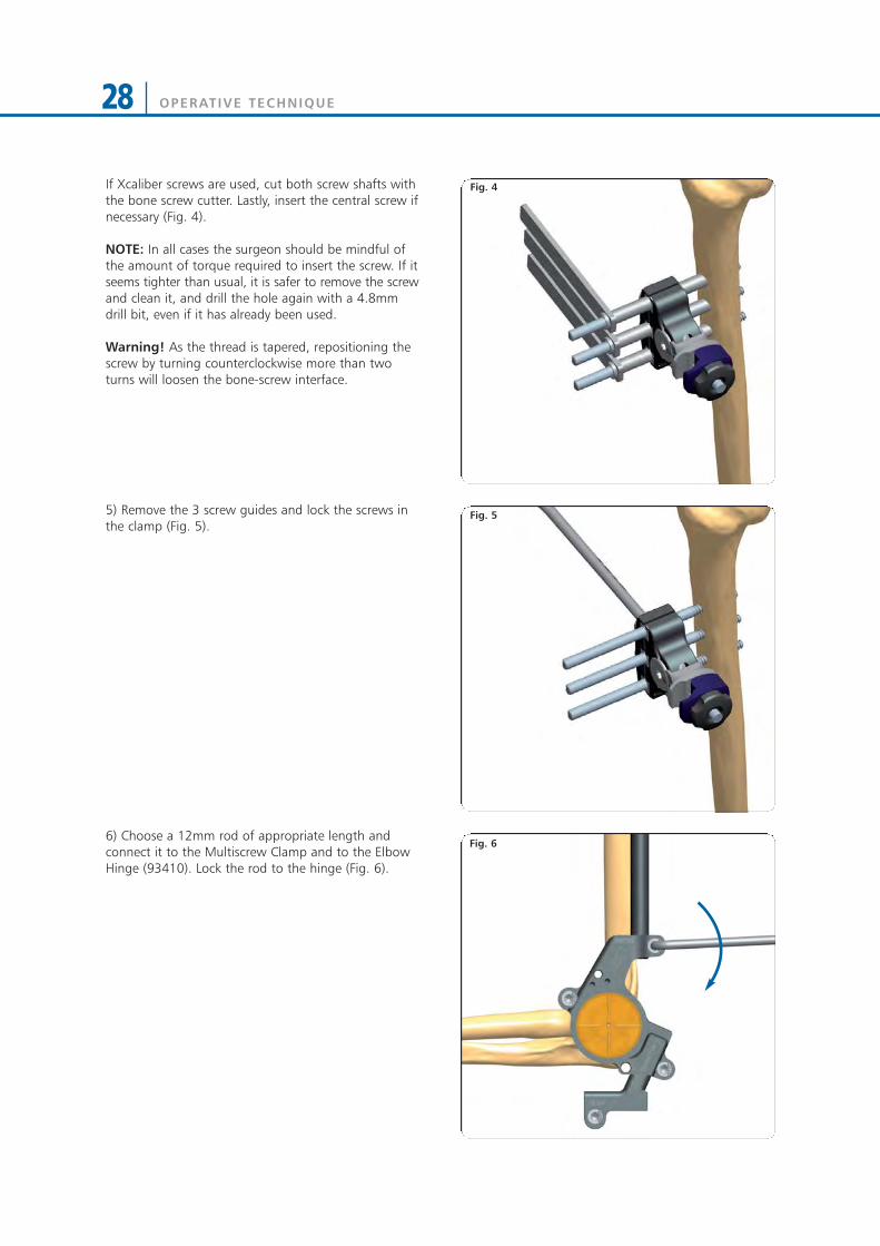
If Xcaliber screws are used, cut both screw shafts withthe bone screw cutter. Lastly, insert the central screw ifnecessary (Fig. 4).
NOTE: In all cases the surgeon should be mindful ofthe amount of torque required to insert the screw. If itseems tighter than usual, it is safer to remove the screwand clean it, and drill the hole again with a 4.8mmdrill bit, even if it has already been used.
Warning! As the thread is tapered, repositioning thescrew by turning counterclockwise more than twoturns will loosen the bone-screw interface.
5) Remove the 3 screw guides and lock the screws inthe clamp (Fig. 5).
6) Choose a 12mm rod of appropriate length andconnect it to the Multiscrew Clamp and to the ElbowHinge (93410). Lock the rod to the hinge (Fig. 6).
Fig. 4
Fig. 5
Fig. 6

OPERATIVE TECHNIQUE 29
The Elbow Hinge needs to be aligned with the centreof rotation of the joint and in order to achieve this: • With the rod parallel to the longitudinal axis of the
humerus, ensure that the Hinge is vertically alignedwith the center of rotation of the joint and lock therod to the Multiscrew Clamp by turning the knurledmetal ring by hand (Fig. 7).
• Move the rod antero-posteriorly to achievehorizontal alignment (Fig. 8).
• Rotate the Elbow Hinge until perfectly aligned withthe center of the elbow joint in the lateral view (Fig. 9).
Fig. 9
Fig. 8
Fig. 7
VerticalAlignment
No HorizontalAlignment
HorizontalAlignment
No VerticalAlignment
OPERATIVE TECHNIQUE30
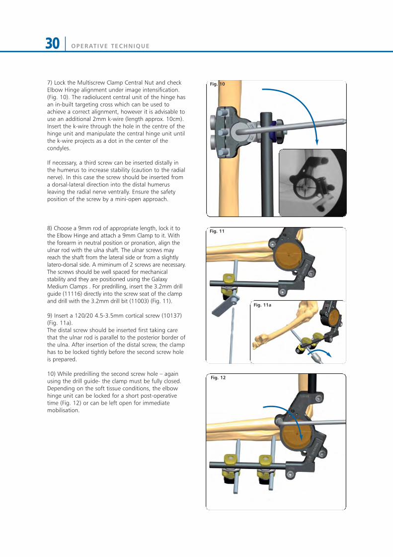
7) Lock the Multiscrew Clamp Central Nut and checkElbow Hinge alignment under image intensification.(Fig. 10). The radiolucent central unit of the hinge hasan in-built targeting cross which can be used toachieve a correct alignment, however it is advisable touse an additional 2mm k-wire (length approx. 10cm).Insert the k-wire through the hole in the centre of thehinge unit and manipulate the central hinge unit untilthe k-wire projects as a dot in the center of thecondyles.
If necessary, a third screw can be inserted distally inthe humerus to increase stability (caution to the radialnerve). In this case the screw should be inserted froma dorsal-lateral direction into the distal humerusleaving the radial nerve ventrally. Ensure the safetyposition of the screw by a mini-open approach.
8) Choose a 9mm rod of appropriate length, lock it tothe Elbow Hinge and attach a 9mm Clamp to it. Withthe forearm in neutral position or pronation, align theulnar rod with the ulna shaft. The ulnar screws mayreach the shaft from the lateral side or from a slightlylatero-dorsal side. A miminum of 2 screws are necessary.The screws should be well spaced for mechanicalstability and they are positioned using the GalaxyMedium Clamps . For predrilling, insert the 3.2mm drillguide (11116) directly into the screw seat of the clampand drill with the 3.2mm drill bit (11003) (Fig. 11).
9) Insert a 120/20 4.5-3.5mm cortical screw (10137)(Fig. 11a).The distal screw should be inserted first taking carethat the ulnar rod is parallel to the posterior border ofthe ulna. After insertion of the distal screw, the clamphas to be locked tightly before the second screw holeis prepared.
10) While predrilling the second screw hole – againusing the drill guide- the clamp must be fully closed. Depending on the soft tissue conditions, the elbowhinge unit can be locked for a short post-operativetime (Fig. 12) or can be left open for immediatemobilisation.
Fig. 10
Fig. 11
Fig. 12
Fig. 11a

OPERATIVE TECHNIQUE 31
Fig. 15
Fig. 14
11) The in-built distraction unit is not necessarily usedin an acute elbow trauma. Sometimes it may help toprotect the joint surfaces but distraction should belimited to 3-4mm. (Fig. 13).
12) Option:Alternatively to the non-invasive targeting techniquedescribed above, it sometimes might be helpful toinsert a 2mm K-wire into the center of the condyles.The K-wire is percutaneously inserted from the lateralside and its tip centered into the radiologically visiblecentre of the condyles (Fig. 14).
13) With the of the K-wire at the entry point of thebone, the K-wire is then drilled approx. 4cm into thebone, along the joint axis both in the lateral and APview (Fig. 15).
Fig. 13

OPERATIVE TECHNIQUE32
14) If the wire has not been inserted exactly along thejoint axis, it is seen as a small line instead of a dot in thelateral view. In this case, under fluoroscopy bend thewire exiting from the skin until it is seen as a single dot(Fig. 16).
15) The elbow assembly is then slid over the K-wireand previously inserted the humeral screws - see abovedescribed technique (Fig. 17).
The Multiscrew Clamp is then closed fully and theapplication of the fixator is continued with theinsertion of the ulnar screws as decribed above.
Fig. 16
Fig. 17
OPERATIVE TECHNIQUE 33
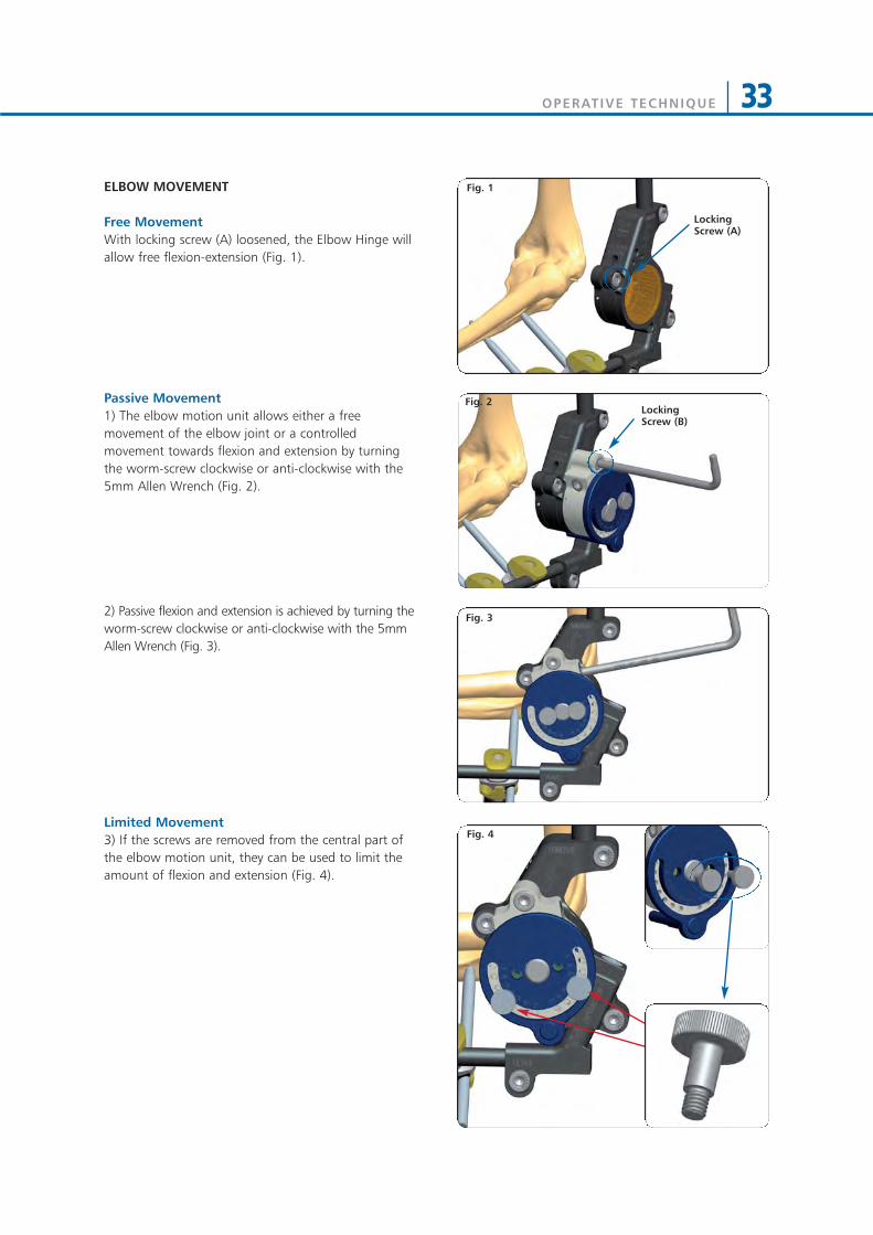
ELBOW MOVEMENT
Free MovementWith locking screw (A) loosened, the Elbow Hinge willallow free flexion-extension (Fig. 1).
Passive Movement1) The elbow motion unit allows either a freemovement of the elbow joint or a controlledmovement towards flexion and extension by turningthe worm-screw clockwise or anti-clockwise with the5mm Allen Wrench (Fig. 2).
2) Passive flexion and extension is achieved by turning theworm-screw clockwise or anti-clockwise with the 5mmAllen Wrench (Fig. 3).
Limited Movement3) If the screws are removed from the central part ofthe elbow motion unit, they can be used to limit theamount of flexion and extension (Fig. 4).
Fig. 3
Fig. 1
Fig. 4
Locking Screw (A)
Locking Screw (B)
Fig. 2
OPERATIVE TECHNIQUE34
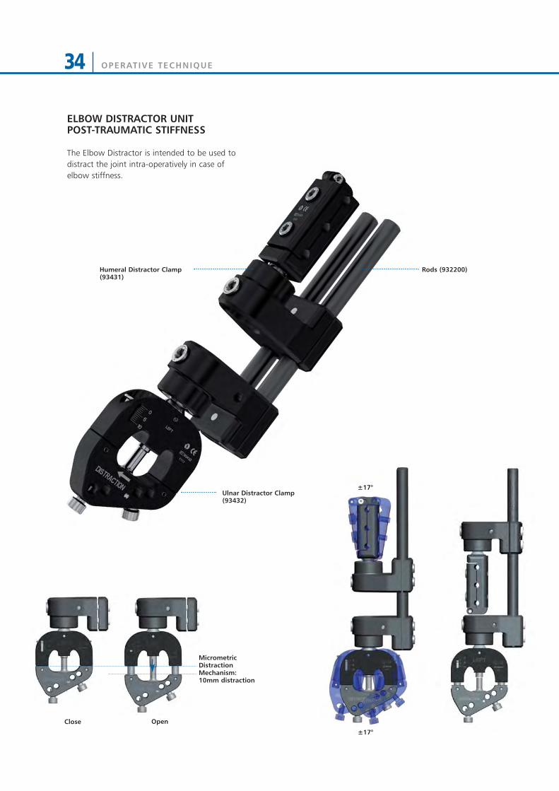
ELBOW DISTRACTOR UNITPOST-TRAUMATIC STIFFNESS
Rods (932200)
Ulnar Distractor Clamp(93432)
±17°
Humeral Distractor Clamp(93431)
MicrometricDistractionMechanism:10mm distraction
The Elbow Distractor is intended to be used todistract the joint intra-operatively in case ofelbow stiffness.
Close Open
±17°

OPERATIVE TECHNIQUE 35
30°
1) It is mandatory to expose or free the ulnar nerveprior to distraction and arthrolysis (Fig. 1).
2) Cleaning of the joint might be necessary prior tothe application of the Elbow Distractor.Expose the lateral aspect of the Humerus by bluntdissection in order to avoid damage to the radialnerve, taking into account that the proximal screwsare inserted first, on the antero-lateral side, at anangle of 10-15° to the frontal plane (Fig. 2).
NOTE: The middle segment of the Humerus (shadedin red) should be avoided as the radial nerve has avariable course in this area.
3) Use the Humeral Distractor Clamp as a template forscrew insertion. Insert the Screw Guides into theclamp, perpendicular to the longitudinal axis of thebone, and position the Trocar (19950) into one of theouter holes to locate the midline by palpation (Fig. 3).
Fig. 1
Fig. 3
Fig. 2

OPERATIVE TECHNIQUE36
4) Keeping the Screw Guide (11137) in contact withthe cortex by gentle pressure, withdraw the Trocar(19955), and tap the Screw Guide lightly to anchor itsdistal end. Insert the 4.8mm Drill Guide (11138) intothe Screw Guide, and introduce a 4.8mm Drill Bit(11001) (Fig. 4).Drill at 500-600 rpm through the first cortex, checking that the Drill Bit is at right angles to thebone. The force applied to the drill should be firm.Use a sharp drill and make sure that the drilling time isas short as possible to avoid thermal damage.
NOTE: The positions of the screw seats in the Humeral Distractor Clamp refer to the screw seats of the Galaxy Multiscrew Clamp or the 1, 3, 5 screwseats of the LRS ADV Straight Clamps.
5) Once the second cortex has been reached, reducethe drilling speed and continue through the bone.Ensure that the drill bit completely penetrates thesecond cortex. Remove the Drill Bit and Drill Guide,keeping pressure on the handle of the Screw Guide.Insert a 110/30 cortical screw (10110) or if necessary alonger screw through the Screw Guide into the boneusing the Universal T Wrench (93150+93155) (Fig. 5).
While inserting the screw, the T Wrench should beheld steady so that the direction of insertion ismaintained throughout the procedure. Make sure thatthe tip of the screw protrudes through the distalcortex (Image Intensifier).
6) Insert the second screw in the outermost hole usingthe same technique. If XCaliber screws are used, cutboth screw shafts with the Bone Screw Cutter (91101).Lastly, insert the middle screw if necessary.Remove the Screw Guides and tighten the clamp (Fig. 6).
NOTE: In all cases, the surgeon should be mindful of the amount of torque required to insert the screw.If it seems tighter than usual, it is safer to remove the screw and clean it, and drill the hole again with a 4.8mm Drill Bit, even if it has already been used.
Warning! As the thread is tapered, repositioning thescrew by turning counterclockwise more than twoturns will loosen the bone-screw interface.
Fig. 4
Fig. 5
Fig. 6
OPERATIVE TECHNIQUE 37
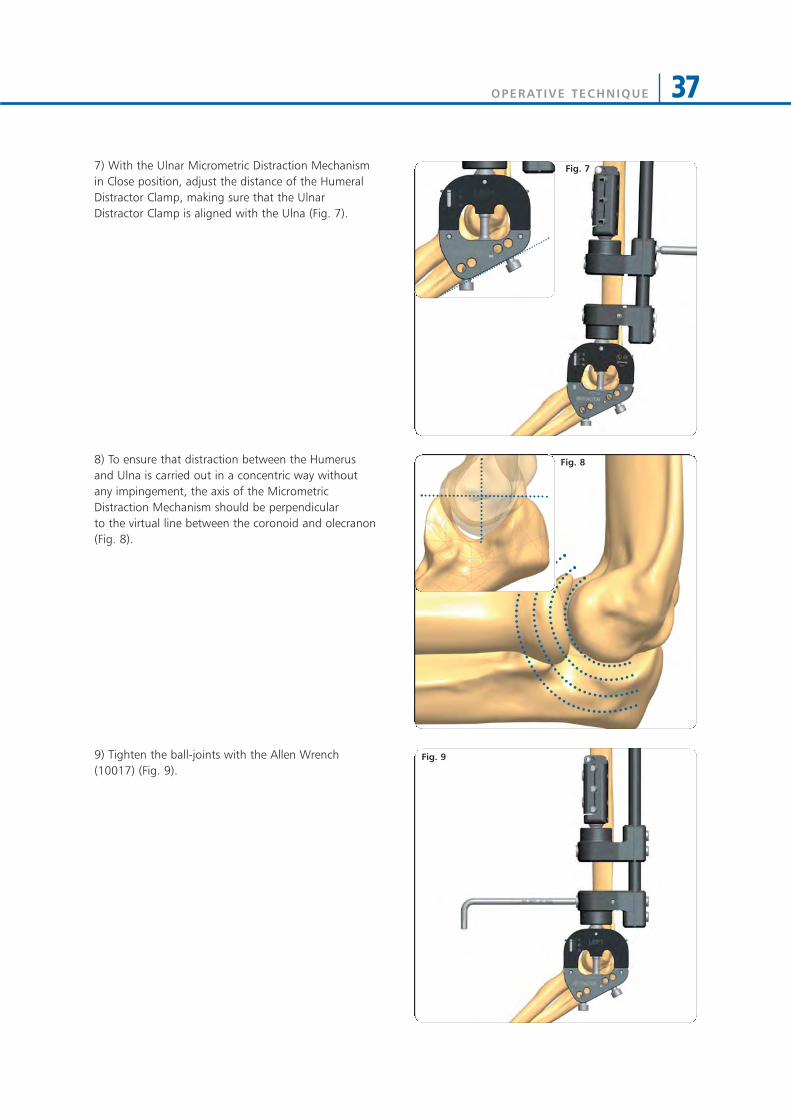
7) With the Ulnar Micrometric Distraction Mechanismin Close position, adjust the distance of the HumeralDistractor Clamp, making sure that the UlnarDistractor Clamp is aligned with the Ulna (Fig. 7).
8) To ensure that distraction between the Humerusand Ulna is carried out in a concentric way withoutany impingement, the axis of the MicrometricDistraction Mechanism should be perpendicular to the virtual line between the coronoid and olecranon(Fig. 8).
9) Tighten the ball-joints with the Allen Wrench(10017) (Fig. 9).
Fig. 7
Fig. 8
Fig. 9

OPERATIVE TECHNIQUE38
10) Insert now the temporary ulnar screws fordistraction. Position the Trocar (19955) in one of theavailable holes of the Ulnar Distractor Clamp andlocate the bone. The distal screw is usually insertedfirst, preferably opposite to the coronoid process.Remove the Trocar, insert a 3.2mm Drill Guide (19950)and drill with a 3.2mm Drill Bit (11003) (Fig. 10a).Insert a 4.5-3.5mm bone screw (10135 or 10137) (Fig.10b).
11) If necessary, adjust the position of the UlnarDistractor Clamp so that its distal border is alignedwith the ulna (Fig. 11b). Insert a second ulnar screw inone of the remaing holes of the Ulnar DistractorClamp using the same procedure. This second screwshould enter the olecranon.
12) Tighten the screw into the clamp with the 5mmAllen Wrench (30017) and tighten the cams with the6mm Torque Wrench (10025) (Fig. 12).
13) Apply joint distraction by turning the MicrometricDistraction Mechanism with 5mm Torque Wrench(93440) which indicates the distraction force (9 Nmcorrespond approximately to 100 Kg of distractionforce) (Fig. 13a e 13b). Joint distraction is checkedunder image intensification and the appropriateamount of distraction should be decided by thesurgeon, in accordance with clinical and radiologicalfindings.
During the distraction process, the ulnar nerve shouldbe monitored closely to make sure that there is notension on the nerve. If necessary the ulnar nerve hasto be trans-posed to the ventral side. The distractionprocess should be repeated 2-3 times and might take5-10 minutes to relax the capsule and the collagenefibres in the ligaments. At the end, release thedistraction, remove the temporary ulnar screws andthe Elbow Distractor.
Fig. 10a Fig. 10b
Fig. 11a Fig. 11b
Fig. 12
Fig. 13a Fig. 13b
OPERATIVE TECHNIQUE 39
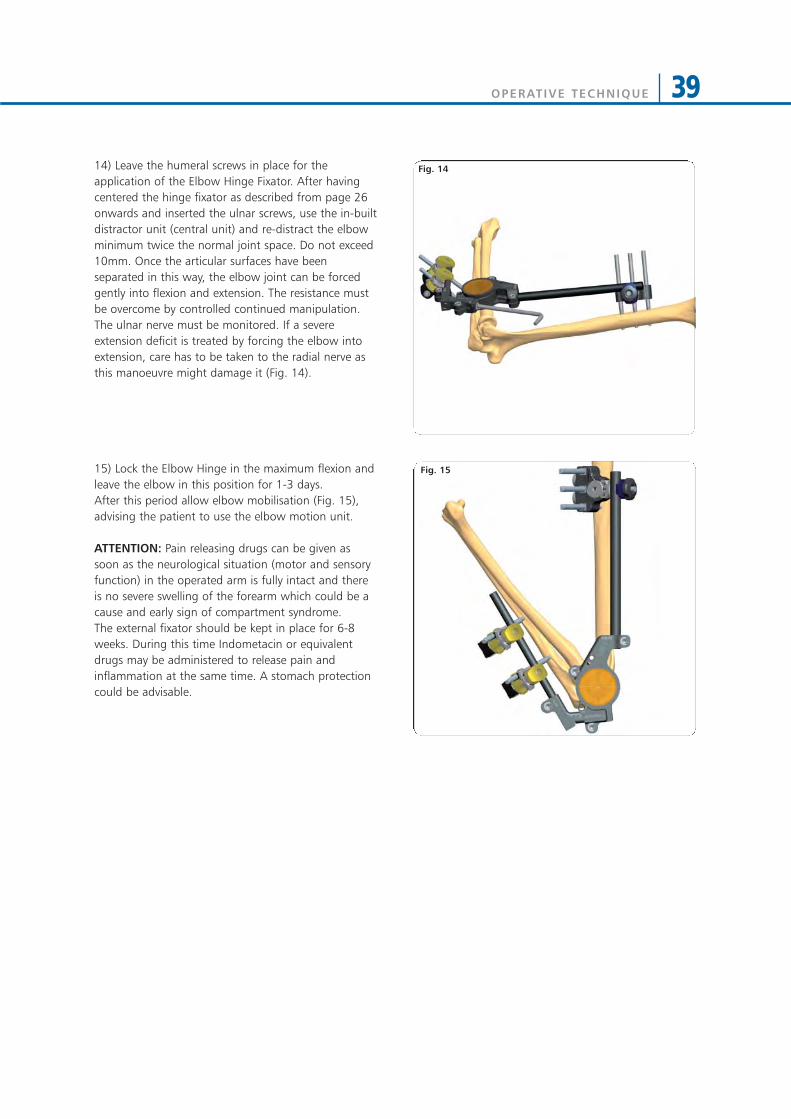
Fig. 1414) Leave the humeral screws in place for theapplication of the Elbow Hinge Fixator. After havingcentered the hinge fixator as described from page 26onwards and inserted the ulnar screws, use the in-builtdistractor unit (central unit) and re-distract the elbowminimum twice the normal joint space. Do not exceed10mm. Once the articular surfaces have beenseparated in this way, the elbow joint can be forcedgently into flexion and extension. The resistance mustbe overcome by controlled continued manipulation.The ulnar nerve must be monitored. If a severeextension deficit is treated by forcing the elbow intoextension, care has to be taken to the radial nerve asthis manoeuvre might damage it (Fig. 14).
15) Lock the Elbow Hinge in the maximum flexion andleave the elbow in this position for 1-3 days.After this period allow elbow mobilisation (Fig. 15),advising the patient to use the elbow motion unit.
ATTENTION: Pain releasing drugs can be given assoon as the neurological situation (motor and sensoryfunction) in the operated arm is fully intact and thereis no severe swelling of the forearm which could be acause and early sign of compartment syndrome. The external fixator should be kept in place for 6-8weeks. During this time Indometacin or equivalentdrugs may be administered to release pain andinflammation at the same time. A stomach protectioncould be advisable.
Fig. 15
Fig. 14
OPERATIVE TECHNIQUE40
WRIST APPLICATIONS
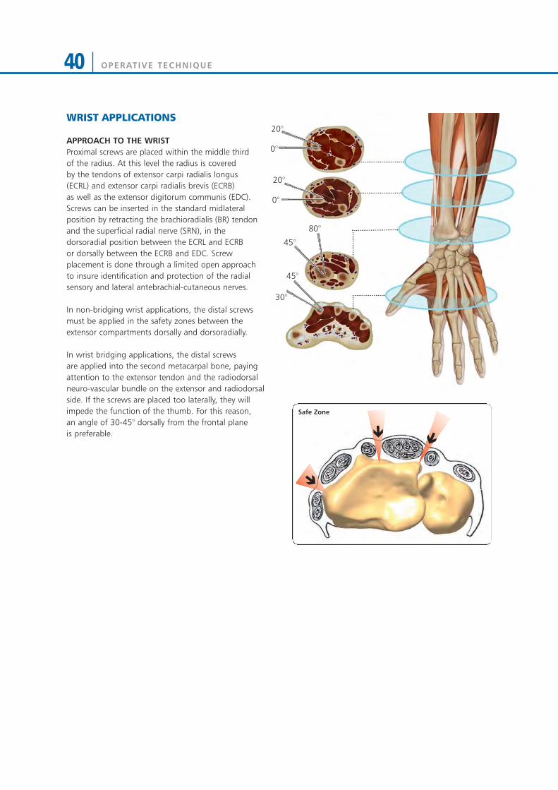
APPROACH TO THE WRISTProximal screws are placed within the middle third of the radius. At this level the radius is covered by the tendons of extensor carpi radialis longus (ECRL) and extensor carpi radialis brevis (ECRB) as well as the extensor digitorum communis (EDC).Screws can be inserted in the standard midlateralposition by retracting the brachioradialis (BR) tendonand the superficial radial nerve (SRN), in thedorsoradial position between the ECRL and ECRB or dorsally between the ECRB and EDC. Screwplacement is done through a limited open approach to insure identification and protection of the radialsensory and lateral antebrachial-cutaneous nerves.
In non-bridging wrist applications, the distal screwsmust be applied in the safety zones between theextensor compartments dorsally and dorsoradially.
In wrist bridging applications, the distal screws are applied into the second metacarpal bone, payingattention to the extensor tendon and the radiodorsalneuro-vascular bundle on the extensor and radiodorsalside. If the screws are placed too laterally, they willimpede the function of the thumb. For this reason, an angle of 30-45° dorsally from the frontal plane is preferable.
0°
20°
0°
20°
45°
80°
30°
45°
Safe Zone

OPERATIVE TECHNIQUE 41
INTRA-ARTICULAR APPLICATION
Surgical Area Preparation• Regional or general anaesthesia may be used• Tourniquet should be available if desired• Use a hand table • Make sure that X-ray equipment is available• Reduce approximately the fracture before the fixator is
applied• Place the wrist in moderate (manual) traction, flexion
and radial abduction (i.e. ulnar deviation) with a foldedtowel on the ulnar side to support it (Fig. 1)
Distal Screws Insertion• Insert first the proximal metacarpal screw close to the
base of the bone on the flare of the tubercle• Make a longitudinal incision to the skin for each
metacarpal screw• Dissect the soft tissues down to the bone taking care to
retract the interosseus muscle anteriorly and theextensor muscle dorsally
• The screw guide is positioned on the bone with thetrocar (19965) (Fig. 2)
Fig. 1
Fig. 2

OPERATIVE TECHNIQUE42
• Insert the screw following one of the screwinsertion techniques described below:
*Pre-drilled Bone Screws (4mm shaft) Insertion• Remove the trocar, replace it with the drill guide and
drill the bone over the drill guide with a 2.7mm drill bit(Fig. 3)
• Insert a bone screw with the T-Wrench 4mm Shaft(93175) or the T-Wrench (M210) over the screw guide(Fig. 4)
Cylindrical Bone Screws (4mm shaft) and *Self-drilling Bone Screws (3 or 4mm shaft) Insertion• Remove the trocar and insert the screws directly
through the screw guide without pre-drilling. In case of the 4mm cylindrical screws, they are insertedusing either the Screw T-Wrench QC (93160) orpower drill with moderate speed. In case of the3mm or 4mm shaft conical screws, they are insertedusing either the T-Wrench (M210) or power drillwith moderate speed (Fig. 5)
NOTES: • Take care to avoid damage to the carpo-metacarpal
joint • There is no need for the tip of the screw to protrude
from the second cortex• Great care must be taken to ensure that the screws
are inserted in the central bone axis
* WARNING: Due to their tapered design, screwsbecome loose if they are backed out
Fig. 4
Fig. 5
Fig. 3
OPERATIVE TECHNIQUE 43
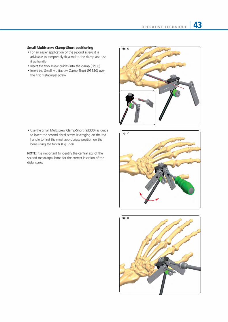
Fig. 6Small Multiscrew Clamp-Short positioning• For an easier application of the second screw, it is
advisable to temporarily fix a rod to the clamp and useit as handle
• Insert the two screw guides into the clamp (Fig. 6)• Insert the Small Multiscrew Clamp-Short (93330) over
the first metacarpal screw
• Use the Small Multiscrew Clamp-Short (93330) as guideto insert the second distal screw, leveraging on the rod-handle to find the most appropriate position on thebone using the trocar (Fig. 7-8)
NOTE: it is important to identify the central axis of thesecond metacarpal bone for the correct insertion of thedistal screw
Fig. 8
Fig. 7
OPERATIVE TECHNIQUE44
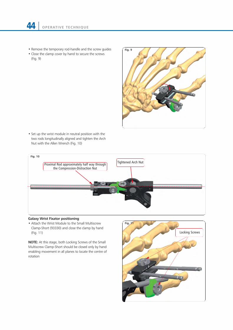
Fig. 9• Remove the temporary rod-handle and the screw guides• Close the clamp cover by hand to secure the screws
(Fig. 9)
• Set up the wrist module in neutral position with thetwo rods longitudinally aligned and tighten the ArchNut with the Allen Wrench (Fig. 10)
Galaxy Wrist Fixator positioning• Attach the Wrist Module to the Small Multiscrew
Clamp-Short (93330) and close the clamp by hand (Fig. 11)
NOTE: At this stage, both Locking Screws of the SmallMultiscrew Clamp-Short should be closed only by handenabling movement in all planes to locate the centre ofrotation
Fig. 10
Tightened Arch Nut
Fig. 11
Locking Screws
Proximal Rod approximately half way throughthe Compression-Distraction Nut
OPERATIVE TECHNIQUE 45
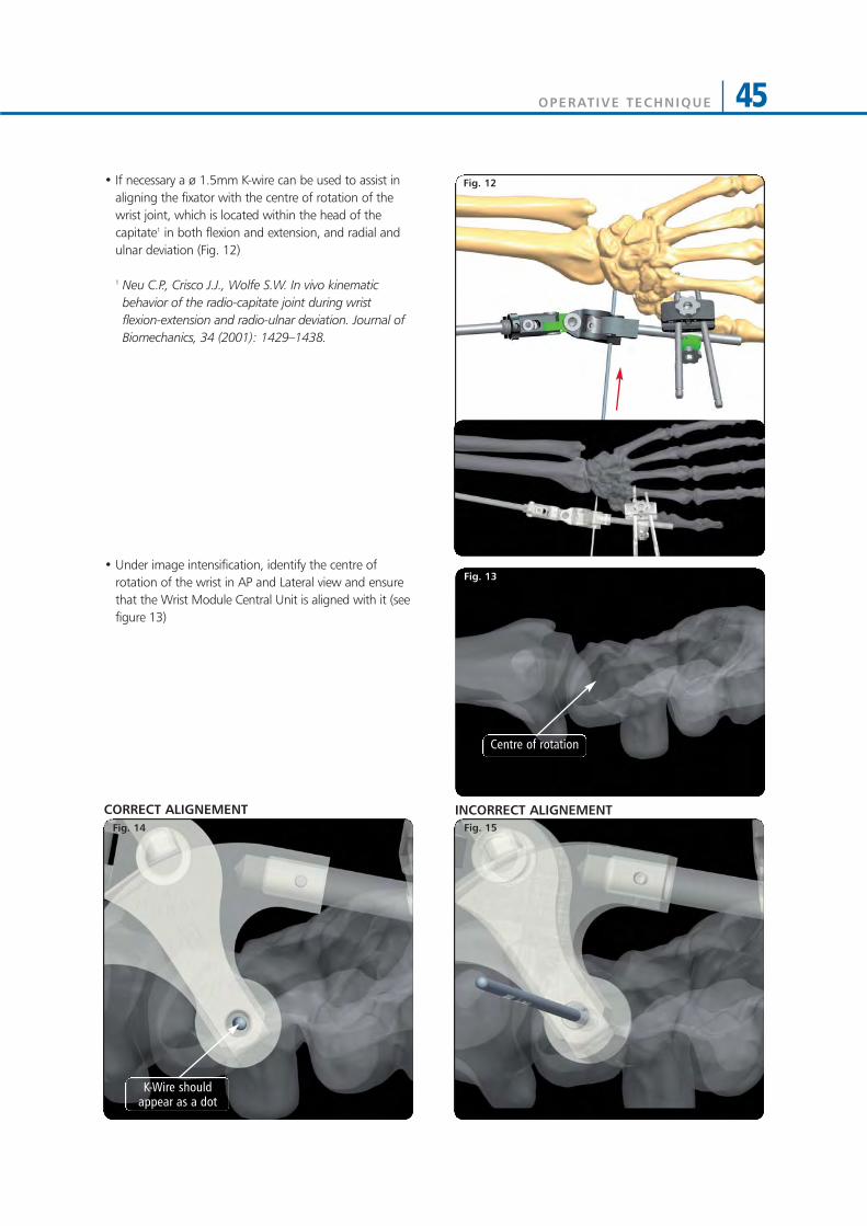
• If necessary a ø 1.5mm K-wire can be used to assist inaligning the fixator with the centre of rotation of thewrist joint, which is located within the head of thecapitate1 in both flexion and extension, and radial andulnar deviation (Fig. 12)
1 Neu C.P., Crisco J.J., Wolfe S.W. In vivo kinematicbehavior of the radio-capitate joint during wristflexion-extension and radio-ulnar deviation. Journal ofBiomechanics, 34 (2001): 1429–1438.
• Under image intensification, identify the centre ofrotation of the wrist in AP and Lateral view and ensurethat the Wrist Module Central Unit is aligned with it (seefigure 13)
Fig. 12
Fig. 13
Fig. 15Fig. 14
INCORRECT ALIGNEMENTCORRECT ALIGNEMENT
Centre of rotation
K-Wire shouldappear as a dot
OPERATIVE TECHNIQUE46
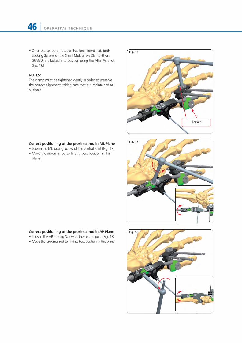
• Once the centre of rotation has been identified, bothLocking Screws of the Small Multiscrew Clamp-Short(93330) are locked into position using the Allen Wrench(Fig. 16)
NOTES:The clamp must be tightened gently in order to preservethe correct alignment, taking care that it is maintained atall times
Correct positioning of the proximal rod in ML Plane• Loosen the ML locking Screw of the central joint (Fig. 17)• Move the proximal rod to find its best position in this
plane
Correct positioning of the proximal rod in AP Plane• Loosen the AP locking Screw of the central joint (Fig. 18) • Move the proximal rod to find its best position in this plane
Fig. 16
Fig. 18
Fig. 17
Locked

OPERATIVE TECHNIQUE 47
• Mount the second Small Multiscrew Clamp-Short(93330) over the proximal rod and lock it in place
• Make a longitudinal skin incision for each screw• Dissect the soft tissues down to the bone taking care to
retract the soft tissues• The screw guide is positioned with the trocar over the
Small Multiscrew Clamp-Short (93330)
• Insert the proximal screws following one of the belowscrew insertion techniques (Fig. 20):
*Pre-drilled Bone Screws (4mm shaft) Insertion• Remove the trocar, replace it with the drill guide and
drill the bone over the drill guide with a 2.7mm drill bit• Insert a bone screw with the T-Wrench 4mm Shaft
(93175) or the T-Wrench (M210) over the screw guide
Cylindrical Bone Screws (4mm shaft) and *Self-drilling Bone Screws (3 or 4mm shaft) Insertion• Remove the trocar and insert the screws directly
through the screw guide without pre-drilling. In case ofthe 4mm cylindrical screws, they are inserted usingeither the Screw T-Wrench QC (93160) or power drillwith moderate speed. In case of the 3mm or 4mmshaft conical screws, they are inserted using either the T-Wrench (M210) or power drill with moderate speed
NOTES:• Pay attention to the safe corridors during pin insertion,
taking care to avoid tendon entrapment and radialnerve damage
• There is no need for the tip of the screw to protrudefrom the second cortex
• Great care must be taken to ensure that the screws areinserted in the central bone axis
• Once they have been placed, an X-Ray should be usedto verify the position and penetration of the far cortexby all four screws
• Remove the screw guides and close the clamp cover byhand (Fig. 21).
* WARNING: Due to their tapered design, screwsbecome loose if they are backed out
Fig. 19
Fig. 20
Fig. 21
OPERATIVE TECHNIQUE48
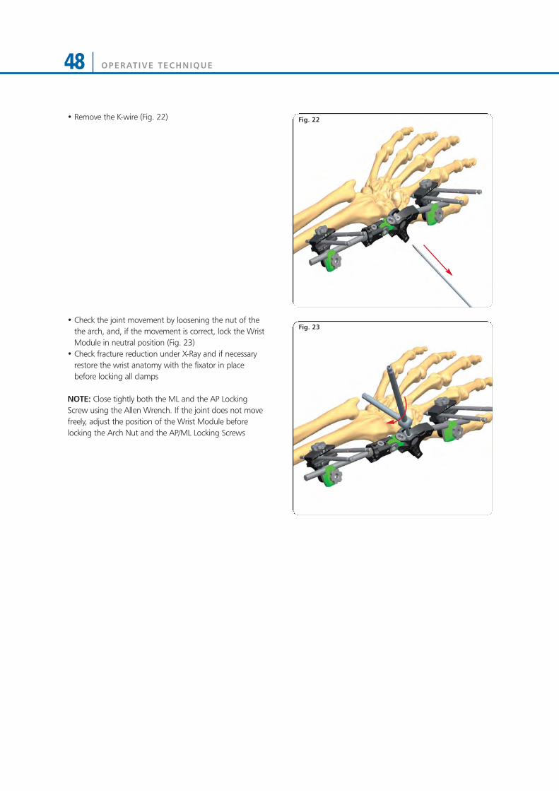
Fig. 22• Remove the K-wire (Fig. 22)
• Check the joint movement by loosening the nut of thethe arch, and, if the movement is correct, lock the WristModule in neutral position (Fig. 23)
• Check fracture reduction under X-Ray and if necessaryrestore the wrist anatomy with the fixator in placebefore locking all clamps
NOTE: Close tightly both the ML and the AP LockingScrew using the Allen Wrench. If the joint does not movefreely, adjust the position of the Wrist Module beforelocking the Arch Nut and the AP/ML Locking Screws
Fig. 23
OPERATIVE TECHNIQUE 49
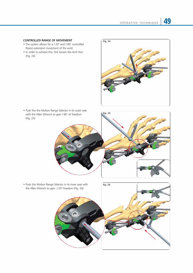
CONTROLLED RANGE OF MOVEMENT• The system allows for a 20° and 40° controlled
flexion-extension movement of the wrist• In order to achieve this, first loosen the Arch Nut
(Fig. 24)
• Push the the Motion Range Selector in its outer seatwith the Allen Wrench to gain 40° of freedom (Fig. 25)
• Push the Motion Range Selector in its inner seat withthe Allen Wrench to gain 20° freedom (Fig. 26)
Fig. 25
Fig. 26
Fig. 24
OPERATIVE TECHNIQUE50
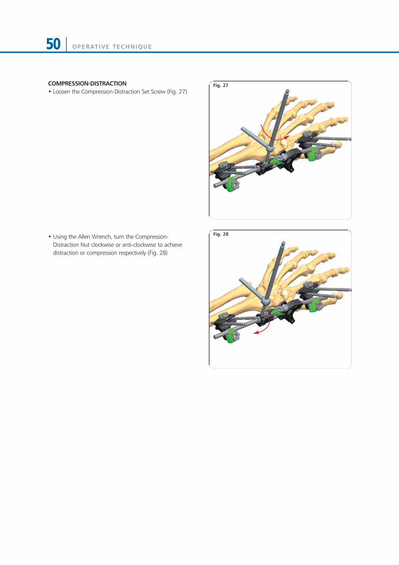
COMPRESSION-DISTRACTION• Loosen the Compression-Distraction Set Screw (Fig. 27)
• Using the Allen Wrench, turn the Compression-Distraction Nut clockwise or anti-clockwise to achievedistraction or compression respectively (Fig. 28)
Fig. 27
Fig. 28
OPERATIVE TECHNIQUE 51
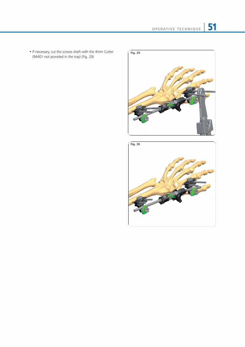
• If necessary, cut the screws shaft with the 4mm Cutter(94401-not provided in the tray) (Fig. 29)
Fig. 30
Fig. 29

OPERATIVE TECHNIQUE52
EXTRA-ARTICULAR APPLICATION
• If there is no extra-articular involvement of the fractureline and the epiphyseal fragment has a volar length of10mm minimum, bridging of the joint is not requiredand the following technique is applicable
Surgical Area Preparation• Regional or general anaesthesia may be used• Tourniquet should be available if desired• Use a hand table • Make sure that X-ray equipment is available• Sterilise the skin over the iliac crest in case a bone graft
should be needed• Reduce approximately the fracture before the fixator is
applied• Place the wrist in moderate (manual) traction, flexion
and radial abduction (i.e. ulnar deviation) with a foldedtowel on the ulnar side to support it (Fig. 31)
• Identify the Lister turbercle and the safe corridors
Distal Screws Insertion• Make a longitudinal incision to the skin for each screw,
making sure to follow safe corridors• Dissect the soft tissues down to the bone taking care to
retract the muscles • The screw guide is positioned over the bone with the
trocar
Fig. 32
Fig. 31
OPERATIVE TECHNIQUE 53
Fig. 34
Fig. 35
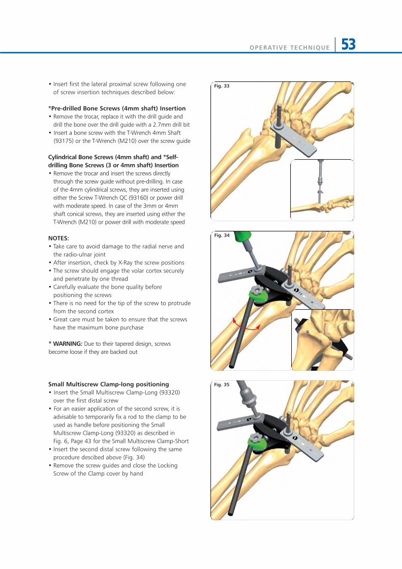
Fig. 33• Insert first the lateral proximal screw following oneof screw insertion techniques described below:
*Pre-drilled Bone Screws (4mm shaft) Insertion• Remove the trocar, replace it with the drill guide and
drill the bone over the drill guide with a 2.7mm drill bit• Insert a bone screw with the T-Wrench 4mm Shaft
(93175) or the T-Wrench (M210) over the screw guide
Cylindrical Bone Screws (4mm shaft) and *Self-drilling Bone Screws (3 or 4mm shaft) Insertion• Remove the trocar and insert the screws directly
through the screw guide without pre-drilling. In case of the 4mm cylindrical screws, they are inserted usingeither the Screw T-Wrench QC (93160) or power drillwith moderate speed. In case of the 3mm or 4mmshaft conical screws, they are inserted using either the T-Wrench (M210) or power drill with moderate speed
NOTES:• Take care to avoid damage to the radial nerve and
the radio-ulnar joint • After insertion, check by X-Ray the screw positions • The screw should engage the volar cortex securely
and penetrate by one thread• Carefully evaluate the bone quality before
positioning the screws• There is no need for the tip of the screw to protrude
from the second cortex• Great care must be taken to ensure that the screws
have the maximum bone purchase
* WARNING: Due to their tapered design, screwsbecome loose if they are backed out
Small Multiscrew Clamp-long positioning• Insert the Small Multiscrew Clamp-Long (93320)
over the first distal screw• For an easier application of the second screw, it is
advisable to temporarily fix a rod to the clamp to beused as handle before positioning the SmallMultiscrew Clamp-Long (93320) as described in Fig. 6, Page 43 for the Small Multiscrew Clamp-Short
• Insert the second distal screw following the sameprocedure descibed above (Fig. 34)
• Remove the screw guides and close the LockingScrew of the Clamp cover by hand
OPERATIVE TECHNIQUE54
Fig. 37
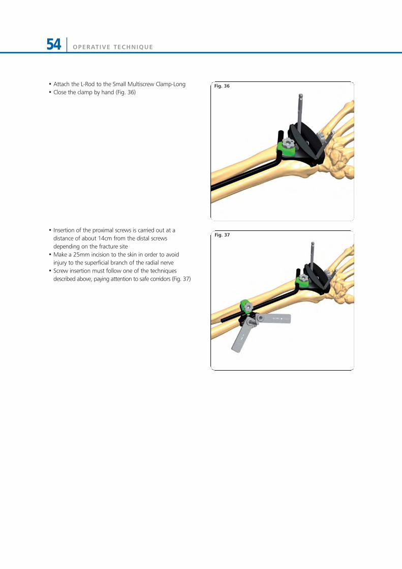
Fig. 36• Attach the L-Rod to the Small Multiscrew Clamp-Long• Close the clamp by hand (Fig. 36)
• Insertion of the proximal screws is carried out at adistance of about 14cm from the distal screwsdepending on the fracture site
• Make a 25mm incision to the skin in order to avoidinjury to the superficial branch of the radial nerve
• Screw insertion must follow one of the techniquesdescribed above, paying attention to safe corridors (Fig. 37)

OPERATIVE TECHNIQUE 55
Fig. 38
Fig. 39
Fig. 40
• All clamps are tightened using the Allen Wrenchavoiding loss of position (Fig. 38)
• If necessary cut the screw shafts with the 4mm Cutter(94401-not provided in the tray) (Fig. 39)

OPERATIVE TECHNIQUE56
Shoulder Humerus
Elbow Forearm
Wrist Wrist
UPPER LIMB APPLICATIONS
OPERATIVE TECHNIQUE 57
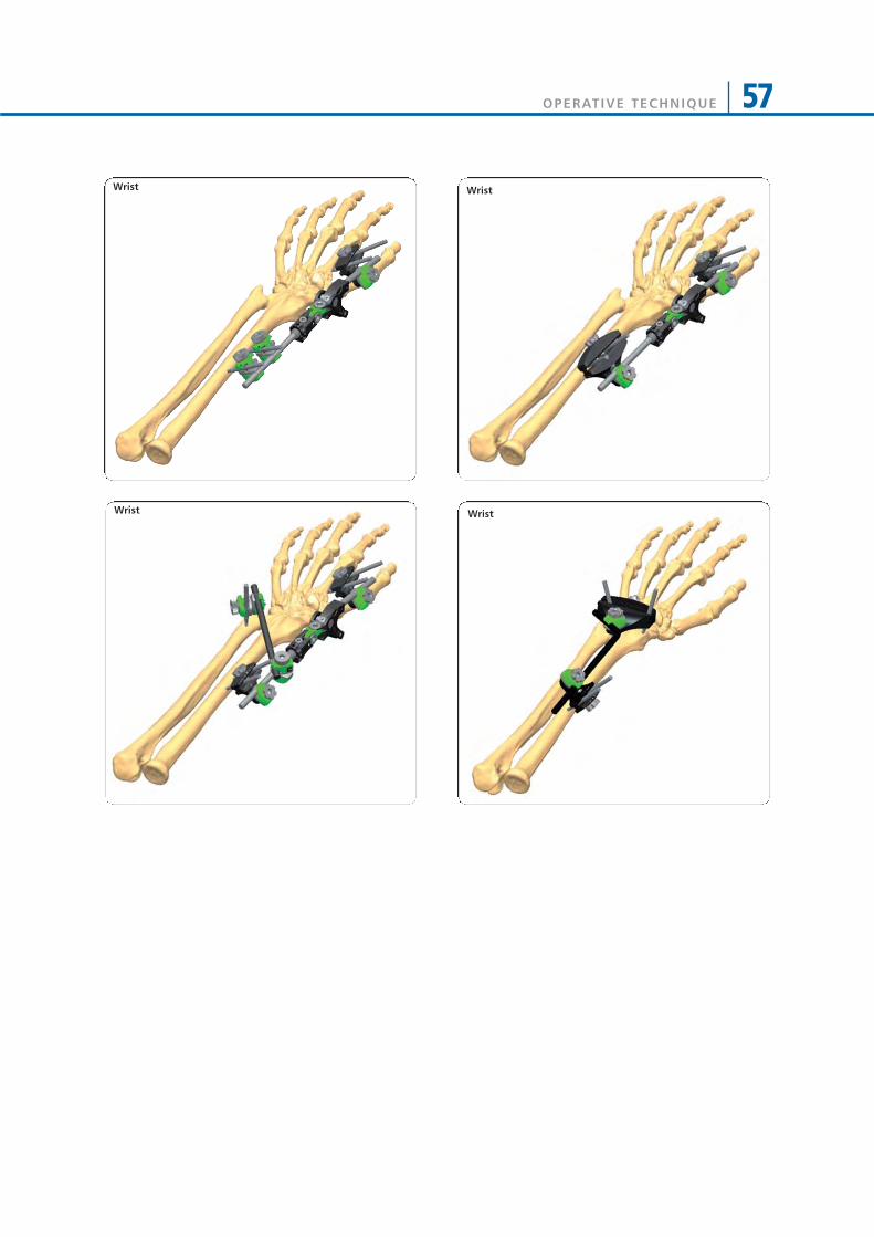
Wrist Wrist
Wrist Wrist

OPERATIVE TECHNIQUE58
MRI INFORMATION
Galaxy System Fixator Components are labeled MR CONDITIONAL according to the terminology specified inASTM F2503 Standard Practice for Marking Medical Devices and Other Items in the Magnetic Resonance Enviroment.
Non-clinical testing has demonstrated that the Galaxy System Fixator Components is MR Conditional according to theterminology specified in ASTM F2503 Standard Practice for Marking Medical Devices and Other Items in theMagnetic Resonance Environment. Non-clinical testing, done according to ASTM F2052-06, F2213-06, F2182–11,F2119-07, demonstrated that a patient with the Galaxy Fixation System can be safely scanned under the followingconditions:• Static magnetic field of 1.5 Tesla and 3.0Tesla• Maximum spatial magnetic field gradient of 900-Gauss/cm (90mT/cm)• Maximum whole-body-averaged specific absorption rate (SAR) of 4.0 W/kg in the First Level Controlled Mode
for 15 minutes of scanning.• No local transmit/receive coils can must be used on the device.• The Galaxy Fixation System must be entirely outside the MR scanner bore. No part of the Galaxy Fixation System
must extend into the MR bore. Therefore MR scanning of body parts where the Galaxy Fixation System is located is Contraindicated.
Note: All components of Galaxy Fixation System frames must be identified as MR Conditional prior to being placedin or near an MR Environment.The Threaded Wires (93100), the Wire Locking Clamps (93620), and the L-Rod (936010) and Semi-Circular Rods(939010, 939020, 939030) are not MR Conditional. Any construct/frame that is using Threaded Wires, the WireLocking Clamps, the L-Rod and Semi-Circular Rods must therefore be considered as MR Unsafe.
HEATING INFORMATIONComprehensive electromagnetic computer modeling and experimental testing was performed on the followingsystems:
1.5-Tesla/64-MHz: Magnetom, Siemens Medical Solutions, Malvern, PA. Software Numaris/4, Version Syngo MR2002B DHHS Active-shielded, horizontal field scanner
3-Tesla/128-MHz: Excite, HDx, Software 14X.M5, General Electric Healthcare, Milwaukee, WI, Active-shielded,horizontal field scanner
to determine the worst heating in ten configurations of Orthofix Galaxy Fixation System. From these studies, it isconcluded that once the entire external fixation frame is visible outside the MRI bore, the maximum heating is lessthan 1 degree Celsius. In non-clinical testing the worst scenarios produced the following temperature rises duringMRI under the conditions reported above:
1.5 Tesla System 3.0 Tesla SystemGalaxy Fixation SystemMinutes of scanning 15 15Calorimetry measured values, whole body averaged SAR (W/kg) 2.2 W/Kg 2.5 W/KgHighest temperature Rise less than (°C) 1°C 1 °C
Please note that temperature changes reported apply to the designed MR systems and characteristics used. If adifferent MR system is used, temperature changes may vary but are expected to be low enough for safe scanning aslong as all Galaxy System Fixator Components are placed outside the MR bore. Since different frame configurationsand frame sizes might lead to higher temperature increases, Orthofix recommends that the SAR settings areminimised as much as possible.
DISPLACEMENT INFORMATIONThe system will not present an additional risk or hazard to a patient in the 3-Tesla 1.5 and MR environment withregard to translational attraction or migration and torque.
ARTIFACT INFORMATIONMR image quality may be compromised if the area of interest is in the same vicinity or relatively close to the positionof the device. For complete information on MR indications, please refer to PQ GAL.
MR

MR PATIENT SAFETYMRI in patients with Galaxy Fixation System can only be performed under these parameters. It is not allowed to scan theGalaxy Fixation System directly. Using other parameters, MRI could result in serious injury to the patient. When theGalaxy Fixation System is used in conjunction with other External Fixation Systems please be advised that thiscombination has not been tested in the MR environment and therefore higher heating and serious injury to the patientmay occur. Because higher in vivo heating cannot be excluded, close patient monitoring and communication with thepatient during the scan is required. Immediately abort the scan if the patient reports burning sensation or pain.
Galaxy Fixation System can only be guaranteed for MRI when using the following components to build a frame: (*the following components are listed in non-sterile configuration. Please consider that the same MRI informationand performance are applicable to the same components in gamma-sterile configuration if available (code numberpreceeded by 99- (e.g 99-93030))
BONE SCREWS*Code Shaft Ø Thread Ø Total L Thread L912630 6 6 - 5,6 260 30912640 6 6 - 5,6 260 40912650 6 6 - 5,6 260 50912660 6 6 - 5,6 260 60912670 6 6 - 5,6 260 70912680 6 6 - 5,6 260 80912690 6 6 - 5,6 260 90911530 6 6 - 5,6 150 30911540 6 6 - 5,6 150 40911550 6 6 - 5,6 150 50911560 6 6 - 5,6 150 60911570 6 6 - 5,6 150 70911580 6 6 - 5,6 150 80911590 6 6 - 5,6 150 9010190 6 4,5 - 3,5 70 2010191 6 4,5 - 3,5 80 2010108 6 4,5 - 3,5 80 3010135 6 4,5 - 3,5 100 2010136 6 4,5 - 3,5 100 3010105 6 4,5 - 3,5 100 4010137 6 4,5 - 3,5 120 2010138 6 4,5 - 3,5 120 3010106 6 4,5 - 3,5 120 4035100 4 3,3 - 3 70 2035101 4 3,3 - 3 80 35948320 4 3 120 20948325 4 3 120 25948335 4 3 120 35947320 4 3 100 20947325 4 3 100 25M310 3 3 - 2,5 50 18M311 3 3 - 2,5 60 20M312 3 3 - 2,5 60 25M313 3 3 - 2,5 60 30M321 3 3 - 2,5 70 15M314 3 3 - 2,5 70 20M315 3 3 - 2,5 70 25M316 3 3 - 2,5 70 30M317 3 3 - 2,5 100 30
RODS*Code Description932100 Rod 100mm long, 12mm diameter932150 Rod 150mm long, 12mm diameter932200 Rod 200mm long, 12mm diameter932250 Rod 250mm long, 12mm diameter932300 Rod 300mm long, 12mm diameter932350 Rod 350mm long, 12mm diameter932400 Rod 400mm long, 12mm diameter939100 Rod 100mm long, 9mm diameter939150 Rod 150mm long, 9mm diameter939200 Rod 200mm long, 9mm diameter939250 Rod 250mm long, 9mm diameter939300 Rod 300mm long, 9mm diameter936060 Rod 60mm long, 6mm diameter936080 Rod 80mm long, 6mm diameter936100 Rod 100mm long, 6mm diameter936120 Rod 120mm long, 6mm diameter936140 Rod 140mm long, 6mm diameter936160 Rod 160mm long, 6mm diameter936180 Rod 180mm long, 6mm diameter936200 Rod 200mm long, 6mm diameter
CLAMPS*Code Description93010 Large Clamp93110 Medium Clamp93310 Small Clamp93020 Multiscrew Clamp93030 Large-Medium Transition Clamp93120 Medium Multiscrew Clamp
ELBOW HINGE*Code Description93410 Elbow Hinge
GALAXY WRIST*Code Description93320 Small Multiscrew Clamp-LONG93330 Small Multiscrew Clamp-SHORT93350 Wrist Module
References1) Summary, conclusions and recommendations: adverse temperature levels in the human body. Goldstein L.S.,
Dewhirst M.W., Repacholi M., Kheifets L. Int. J. Hyperthermia Vol 19 N. 2003 pag 373-384.2) Assessment of bone viability after heat trauma Eriksson R.A., Albrektsson T., Magnusson B. Scand J Plast Reconst
Surg 18:261-68 1984.3) Temperature threshold levels for heat-induced bone tissue injury: A vital-microscopic study in the rabbit Eriksson
A.R., Albrektsson T. J Prosthet Dent. 1983 Jul;50(1):101-7.
OPERATIVE TECHNIQUE 59


www.or thof i x . comGF-1101-OPT-E0 F 09/13
Your Distributor is:Manufactured by: ORTHOFIX SrlVia Delle Nazioni 937012 Bussolengo (Verona)Italy
Telephone +39 045 6719000Fax +39 045 6719380
0123
Instructions for Use: See actual package insert for Instructions for Use.
Caution: Federal law (USA) restricts this device to sale by or on the order of a physician.
Proper surgical procedure is the responsibility of the medical professional. Operative techniques arefurnished as an informative guideline. Each surgeon must evaluate the appropriateness of a techniquebased on his or her personal medical credentials and experience. Please refer to the “Instructions forUse” supplied with the product for specific information on indications for use, contraindications,warnings, precautions, adverse reactions and sterilization.