ga-p55-ud3 manual
TRANSCRIPT

7/29/2019 GA-P55-UD3 Manual
http://slidepdf.com/reader/full/ga-p55-ud3-manual 1/128
GA-P55-UD3P
GA-P55-UD3RLGA1156 socket motherboard for Intel® Core™ i7 processor family/Intel® Core™ i5 processor family
User's ManualRev. 1001
12ME-P55UD3P-1001R

7/29/2019 GA-P55-UD3 Manual
http://slidepdf.com/reader/full/ga-p55-ud3-manual 2/128
M o t h e r b o ar d
GA-P 5 5 - UD 3 P /
GA-P 5 5 - UD 3 R
J ul .1 4 ,2 0 0 9
J u l .1 4 ,2 0 0 9
M o t h e r b o a r d
G A - P 5 5 - U D 3 P / G A - P 5 5 - U D 3 R

7/29/2019 GA-P55-UD3 Manual
http://slidepdf.com/reader/full/ga-p55-ud3-manual 3/128
Copyright
© 2009 GIGA-BYTE TECHNOLOGY CO., LTD. All rights reserved.
The trademarks mentioned in this manual are legally registered to their respective owners.
Disclaimer
Information in this manual is protected by copyright laws and is the property of GIGABYTE.
Changes to the specifications and features in this manual may be made by GIGABYTE
without prior notice. No part of this manual may be reproduced, copied, translated, transmitted,
or published in any form or by any means without GIGABYTE's prior written permission.
Documentation Classications
In order to assist in the use of this product, GIGABYTE provides the following types of documentations:
For quick set-up of the product, read the Quick Installation Guide included with the product.
For detailed product information, carefully read the User's Manual.
For instructions on how to use GIGABYTE's unique features, read or download the information
on/from the Support&Downloads\Motherboard\Technology Guide page on our website.
For product-related information, check on our website at:
http://www.gigabyte.com.tw
Identifying Your Motherboard Revision
The revision number on your motherboard looks like this: "REV: X.X." For example, "REV: 1.0"
means the revision of the motherboard is 1.0. Check your motherboard revision before updating
motherboard BIOS, drivers, or when looking for technical information.
Example:
7/29/2019 GA-P55-UD3 Manual
http://slidepdf.com/reader/full/ga-p55-ud3-manual 4/128
- 4 -
Table of Contents
Box Contents ...................................................................................................................6
Optional Items .................................................................................................................6
GA-P55-UD3P/GA-P55-UD3R Motherboard Layout .......................................................7
Block Diagram .................................................................................................................8
Chapter 1 Hardware Installation .....................................................................................9
1-1 Installation Precautions .................................................................................... 9
1-2 ProductSpecications.................................................................................... 10
1-3 Installing the CPU and CPU Cooler ............................................................... 13
1-3-1 Installing the CPU ...................................................................................................13
1-3-2 Installing the CPU Cooler .......................................................................................15
1-4 Installing the Memory ..................................................................................... 16
1-4-1 DualChannelMemoryConguration .....................................................................16
1-4-2 Installing a Memory ...............................................................................................17
1-5 Installing an Expansion Card ......................................................................... 18
1-6 Back Panel Connectors.................................................................................. 19
1-7 Internal Connectors ........................................................................................ 21
Chapter 2 BIOS Setup ..................................................................................................33
2-1 Startup Screen ............................................................................................... 34
2-2 The Main Menu .............................................................................................. 35
2-3 MB Intelligent Tweaker(M.I.T.) ........................................................................ 37
2-4 Standard CMOS Features .............................................................................. 47
2-5 Advanced BIOS Features .............................................................................. 49
2-6 Integrated Peripherals .................................................................................... 51
2-7 Power Management Setup ............................................................................. 54
2-8 PC Health Status ............................................................................................ 56
2-9 Load Fail-Safe Defaults.................................................................................. 58
2-10 Load Optimized Defaults ................................................................................ 58
2-11 Set Supervisor/User Password ...................................................................... 59
2-12 Save & Exit Setup .......................................................................................... 60
2-13 Exit Without Saving ........................................................................................ 60
2-14 SecurityChipCongurationj ...................................................................... 61

7/29/2019 GA-P55-UD3 Manual
http://slidepdf.com/reader/full/ga-p55-ud3-manual 5/128
- 5 -
Chapter 3 Drivers Installation........................................................................................63
3-1 Installing Chipset Drivers ............................................................................... 633-2 Application Software ...................................................................................... 64
3-3 Technical Manuals .......................................................................................... 64
3-4 Contact ........................................................................................................... 65
3-5 System ........................................................................................................... 65
3-6 Download Center ........................................................................................... 66
3-7 New Utilities ................................................................................................... 66
Chapter 4 Unique Features...........................................................................................674-1 Xpress Recovery2 .......................................................................................... 67
4-2 BIOS Update Utilities ..................................................................................... 70
4-2-1 Updating the BIOS with the Q-Flash Utility .............................................................70
4-2-2 Updating the BIOS with the @BIOS Utility .............................................................73
4-3 EasyTune 6 .................................................................................................... 74
4-4 Dynamic Energy Saver ™ 2 .............................................................................. 75
4-5 Q-Share .......................................................................................................... 77
4-6 Smart 6™ ........................................................................................................ 78
4-7 Smart TPMj ................................................................................................ 81
Chapter 5 Appendix ......................................................................................................83
5-1 ConguringSATAHardDrive(s)..................................................................... 83
5-1-1 ConguringIntelP55SATAControllers.................................................................83
5-1-2 ConguringJMB362/GIGABYTESATA2SATAController ......................................91
5-1-3 Making a SATA RAID/AHCI Driver Diskette............................................................97
5-1-4 Installing the SATA RAID/AHCI Driver and Operating System ...............................98
5-2 ConguringAudioInputandOutput............................................................. 109
5-2-1 Conguring2/4/5.1/7.1-ChannelAudio.................................................................109
5-2-2 ConguringS/PDIFIn/Out....................................................................................111
5-2-3 ConguringMicrophoneRecording ......................................................................113
5-2-4 Using the Sound Recorder ...................................................................................115
5-3 Troubleshooting............................................................................................ 116
5-3-1 Frequently Asked Questions ................................................................................116
5-3-2 Troubleshooting Procedure ..................................................................................117
5-4 Regulatory Statements ................................................................................. 119
j Only for GA-P55-UD3P.
7/29/2019 GA-P55-UD3 Manual
http://slidepdf.com/reader/full/ga-p55-ud3-manual 6/128
- 6 -
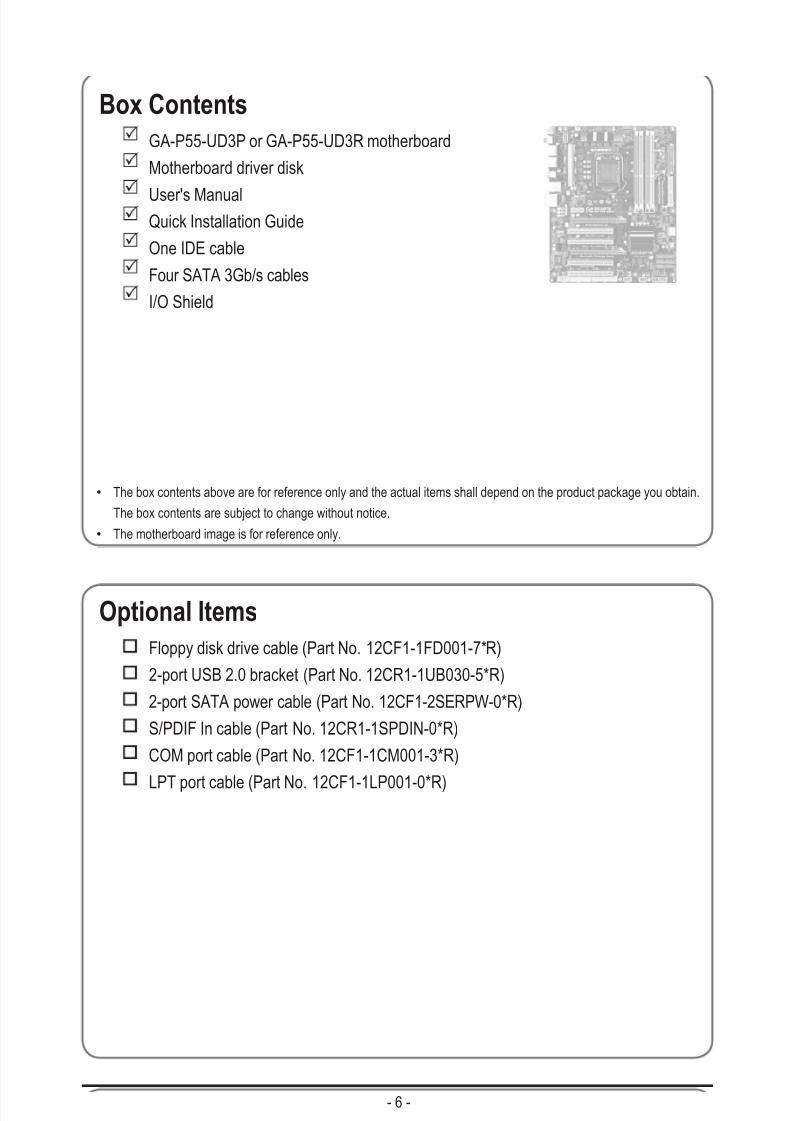
Box Contents
GA-P55-UD3P or GA-P55-UD3R motherboard
Motherboard driver disk
User's ManualQuick Installation Guide
One IDE cable
Four SATA 3Gb/s cables
I/O Shield
Optional Items
Floppy disk drive cable (Part No. 12CF1-1FD001-7*R)
2-port USB 2.0 bracket (Part No. 12CR1-1UB030-5*R)
2-port SATA power cable (Part No. 12CF1-2SERPW-0*R)
S/PDIF In cable (Part No. 12CR1-1SPDIN-0*R)
COM port cable (Part No. 12CF1-1CM001-3*R)
LPT port cable (Part No. 12CF1-1LP001-0*R)
• The box contents above are for reference only and the actual items shall depend on the product package you obtain.
The box contents are subject to change without notice.
• The motherboard image is for reference only.

7/29/2019 GA-P55-UD3 Manual
http://slidepdf.com/reader/full/ga-p55-ud3-manual 7/128
- 7 -
GA-P55-UD3P/GA-P55-UD3R Motherboard Layout
(Note) Due to a hardware limitation, the PCIEX1 slot can only accommodate a shorter PCI Express x1
expansion card. For a longer expansion card, use other expansion slots.
KB_USB
j Only for GA-P55-UD3P.
CPU_FAN
ATX_12V_2X4
ATX
C D
_ I N
AUDIO
B_BIOS
PCIEX4
IDE
S P D I F
_ I
D D R 3
_ 1
D D R 3
_ 3
D D R 3
_ 2
D D R 3
_ 4
BAT
F_PANELF_USB2
COMA
I T 8 7 2 0
Intel® P55
LPT
SATA2_1SATA2_3
SATA2_5
GSATA2_1
SATA2_0
SATA2_2SATA2_4
GSATA2_0
PCI3
PCI4CLR_CMOS
CODEC
SYS_FAN1
M_BIOS
PCI1
PCIEX16
S P D I F
_ O
F_USB1
SYS_FAN2
GIGABYTESATA2
LGA1156
G A - P 5 5 - U D 3 P
/ G A - P
5 5 - U D 3 R
P W R
_ F A N
R_SPDIF
USB_ESATA_1
R_USB
USB_ESATA_2
PHASE LED
USB_LAN
PCI2
FDD
TPM ICj
JMB362
PCIEX1(Note)
F_AUDIO
RTL8111D

7/29/2019 GA-P55-UD3 Manual
http://slidepdf.com/reader/full/ga-p55-ud3-manual 8/128
- 8 -
Block Diagram
j Only for GA-P55-UD3P.
PCIe CLK
(100 MHz)
x16
1 PCI Express x16
C e n t e r / S u b w o o f e r S p e a k e r O u t
L i n e O u t
M I C
L i n e I n
S / P D I F I n
S / P D I F O u t
S
i d e S p e a k e r O u t
S u r r o
u n d S p e a k e r O u t
CODEC
PS/2 KB/Mouse
LGA1156CPU
DMI
Interface
Intel® P55
4 PCI
PCI Bus
PCI CLK
(33 MHz)
PCI Express Bus
CPU CLK+/- (133 MHz)
6 SATA 3Gb/s
Dual BIOS
14 USB Ports
DDR3 2200/1333/1066/800 MHz
Dual Channel Memory
PCI Express Bus
x1
JMB3622 SATA 3Gb/s
COM Port
LPC Bus
IT8720
TPM j
PCIe CLK
(100 MHz)
1 PCI Express x1
PCI Express Bus
x1
ATA-133/100/66/33 IDE Channel
2 SATA 3Gb/s
x1
GIGABYTESATA2
x1
LAN
RJ45
RTL8111D
x4
1 PCI Express x4
Floppy

7/29/2019 GA-P55-UD3 Manual
http://slidepdf.com/reader/full/ga-p55-ud3-manual 9/128
- 9 - Hardware Installation
1-1 Installation Precautions
The motherboard contains numerous delicate electronic circuits and components which can
become damaged as a result of electrostatic discharge (ESD). Prior to installation, carefully read
the user's manual and follow these procedures:
• Prior to installation, do not remove or break motherboard S/N (Serial Number) sticker or
warranty sticker provided by your dealer. These stickers are required for warranty validation.
• Always remove the AC power by unplugging the power cord from the power outlet before
installing or removing the motherboard or other hardware components.
• When connecting hardware components to the internal connectors on the motherboard,
make sure they are connected tightly and securely. • When handling the motherboard, avoid touching any metal leads or connectors.
• It is best to wear an electrostatic discharge (ESD) wrist strap when handling electronic com-
ponents such as a motherboard, CPU or memory. If you do not have an ESD wrist strap,
keepyourhandsdryandrsttouchametalobjecttoeliminatestaticelectricity.
• Prior to installing the motherboard, please have it on top of an antistatic pad or within an
electrostatic shielding container.
• Before unplugging the power supply cable from the motherboard, make sure the power sup-
ply has been turned off.
• Before turning on the power, make sure the power supply voltage has been set according to
the local voltage standard.
• Before using the product, please verify that all cables and power connectors of your hard-
ware components are connected.
• To prevent damage to the motherboard, do not allow screws to come in contact with the
motherboard circuit or its components.
• Make sure there are no leftover screws or metal components placed on the motherboard or
within the computer casing.
• Do not place the computer system on an uneven surface.
• Do not place the computer system in a high-temperature environment.
• Turning on the computer power during the installation process can lead to damage to sys-
tem components as well as physical harm to the user.
• If you are uncertain about any installation steps or have a problem related to the use of the
product,pleaseconsultacertiedcomputertechnician.
Chapter 1 Hardware Installation
7/29/2019 GA-P55-UD3 Manual
http://slidepdf.com/reader/full/ga-p55-ud3-manual 10/128
Hardware Installation - 10 -
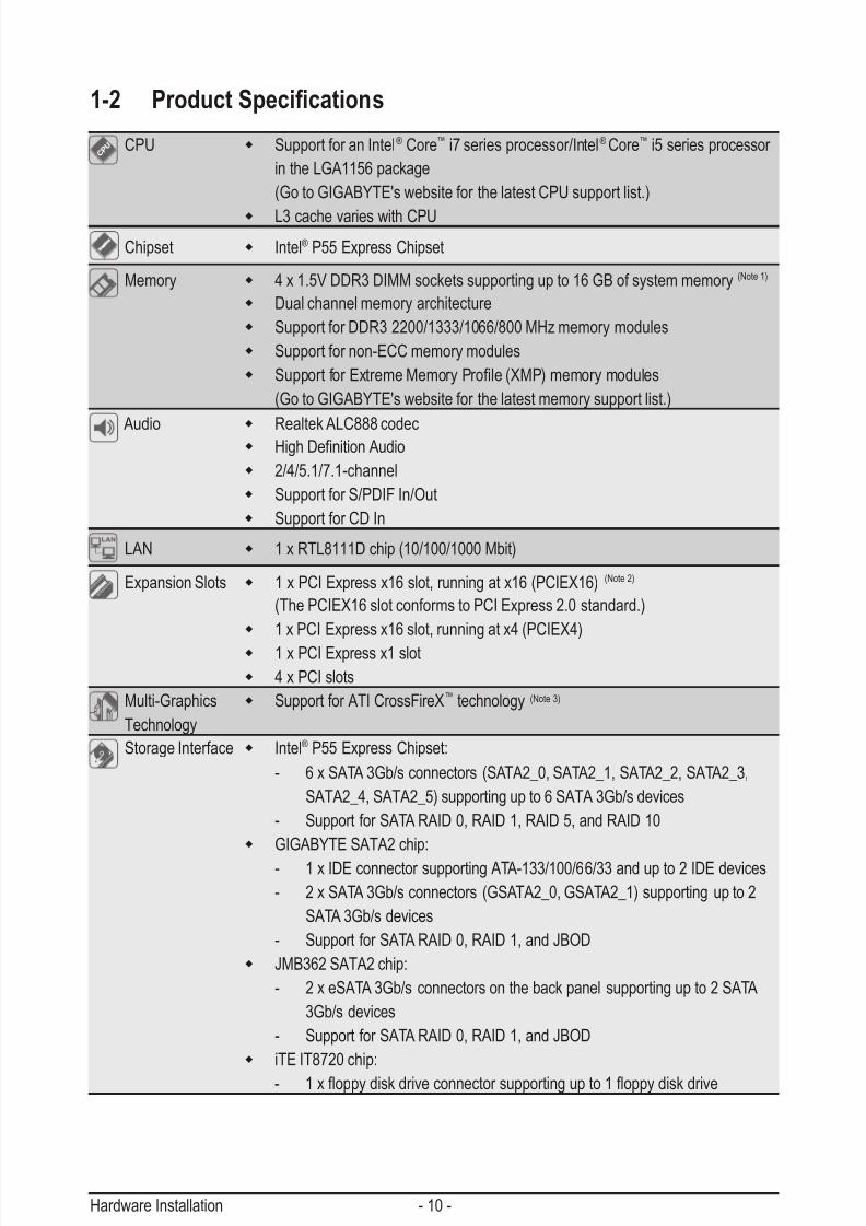
1-2 Product Specications
CPU Support for an Intel® Core™ i7 series processor/Intel® Core™ i5 series processor
in the LGA1156 package
(Go to GIGABYTE's website for the latest CPU support list.)
L3 cache varies with CPU
Chipset Intel® P55 Express Chipset
Memory 4 x 1.5V DDR3 DIMM sockets supporting up to 16 GB of system memory (Note 1)
Dual channel memory architecture
Support for DDR3 2200/1333/1066/800 MHz memory modules
Support for non-ECC memory modules
SupportforExtremeMemoryProle(XMP)memorymodules
(Go to GIGABYTE's website for the latest memory support list.)
Audio
Realtek ALC888 codec HighDenitionAudio
2/4/5.1/7.1-channel
Support for S/PDIF In/Out
Support for CD In
LAN 1 x RTL8111D chip (10/100/1000 Mbit)
Expansion Slots 1 x PCI Express x16 slot, running at x16 (PCIEX16) (Note 2)
(The PCIEX16 slot conforms to PCI Express 2.0 standard.)
1 x PCI Express x16 slot, running at x4 (PCIEX4)
1 x PCI Express x1 slot
4 x PCI slots
Multi-Graphics Support for ATI CrossFireX™ technology (Note 3)
Technology
Storage Interface Intel® P55 Express Chipset:
- 6 x SATA 3Gb/s connectors (SATA2_0, SATA2_1, SATA2_2, SATA2_3,
SATA2_4, SATA2_5) supporting up to 6 SATA 3Gb/s devices
- Support for SATA RAID 0, RAID 1, RAID 5, and RAID 10
GIGABYTE SATA2 chip:
- 1 x IDE connector supporting ATA-133/100/66/33 and up to 2 IDE devices
- 2 x SATA 3Gb/s connectors (GSATA2_0, GSATA2_1) supporting up to 2
SATA 3Gb/s devices
- Support for SATA RAID 0, RAID 1, and JBOD
JMB362 SATA2 chip:
- 2 x eSATA 3Gb/s connectors on the back panel supporting up to 2 SATA
3Gb/s devices
- Support for SATA RAID 0, RAID 1, and JBOD
iTE IT8720 chip:
- 1xoppydiskdriveconnectorsupportingupto1oppydiskdrive
7/29/2019 GA-P55-UD3 Manual
http://slidepdf.com/reader/full/ga-p55-ud3-manual 11/128
- 11 - Hardware Installation
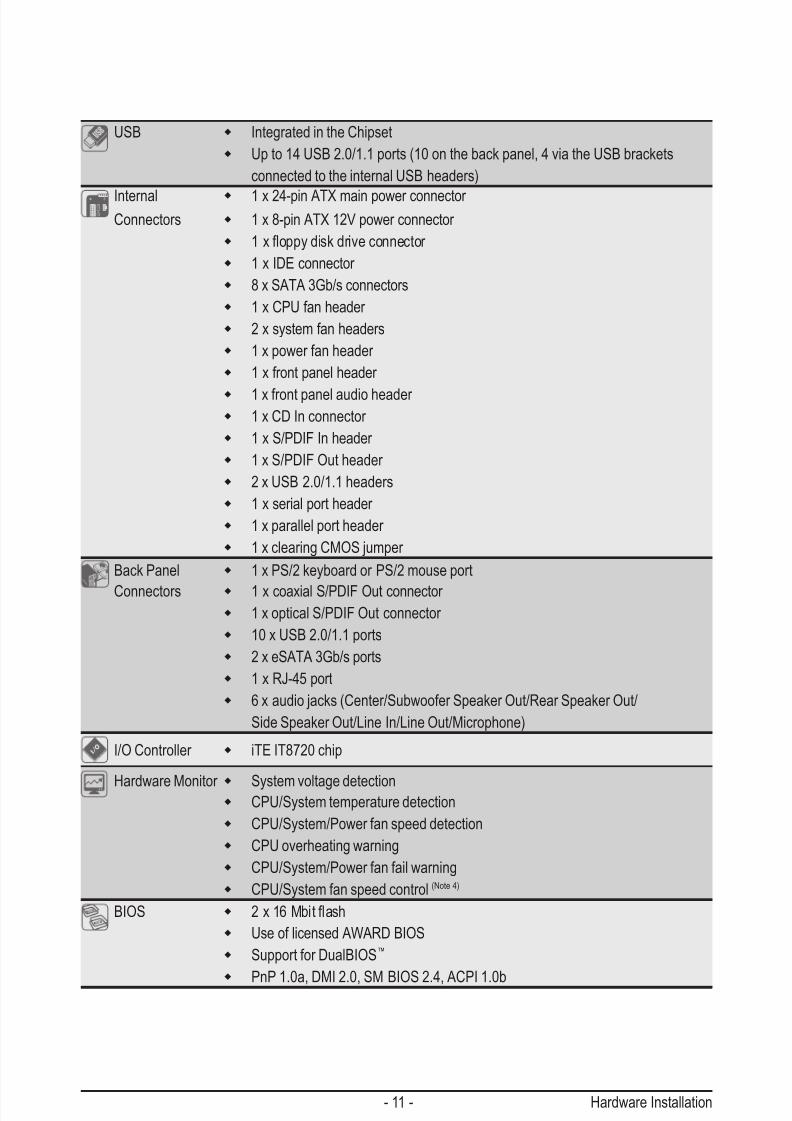
USB Integrated in the Chipset
Up to 14 USB 2.0/1.1 ports (10 on the back panel, 4 via the USB brackets
connected to the internal USB headers)
Internal 1 x 24-pin ATX main power connector Connectors 1 x 8-pin ATX 12V power connector
1xoppydiskdriveconnector
1 x IDE connector
8 x SATA 3Gb/s connectors
1 x CPU fan header
2 x system fan headers
1 x power fan header
1 x front panel header
1 x front panel audio header 1 x CD In connector
1 x S/PDIF In header
1 x S/PDIF Out header
2 x USB 2.0/1.1 headers
1 x serial port header
1 x parallel port header
1 x clearing CMOS jumper
Back Panel 1 x PS/2 keyboard or PS/2 mouse port
Connectors 1 x coaxial S/PDIF Out connector 1 x optical S/PDIF Out connector
10 x USB 2.0/1.1 ports
2 x eSATA 3Gb/s ports
1 x RJ-45 port
6 x audio jacks (Center/Subwoofer Speaker Out/Rear Speaker Out/
Side Speaker Out/Line In/Line Out/Microphone)
I/O Controller iTE IT8720 chip
Hardware Monitor
System voltage detection CPU/System temperature detection
CPU/System/Power fan speed detection
CPU overheating warning
CPU/System/Power fan fail warning
CPU/System fan speed control (Note 4)
BIOS 2x16Mbitash
Use of licensed AWARD BIOS
Support for DualBIOS™
PnP 1.0a, DMI 2.0, SM BIOS 2.4, ACPI 1.0b
7/29/2019 GA-P55-UD3 Manual
http://slidepdf.com/reader/full/ga-p55-ud3-manual 12/128
Hardware Installation - 12 -
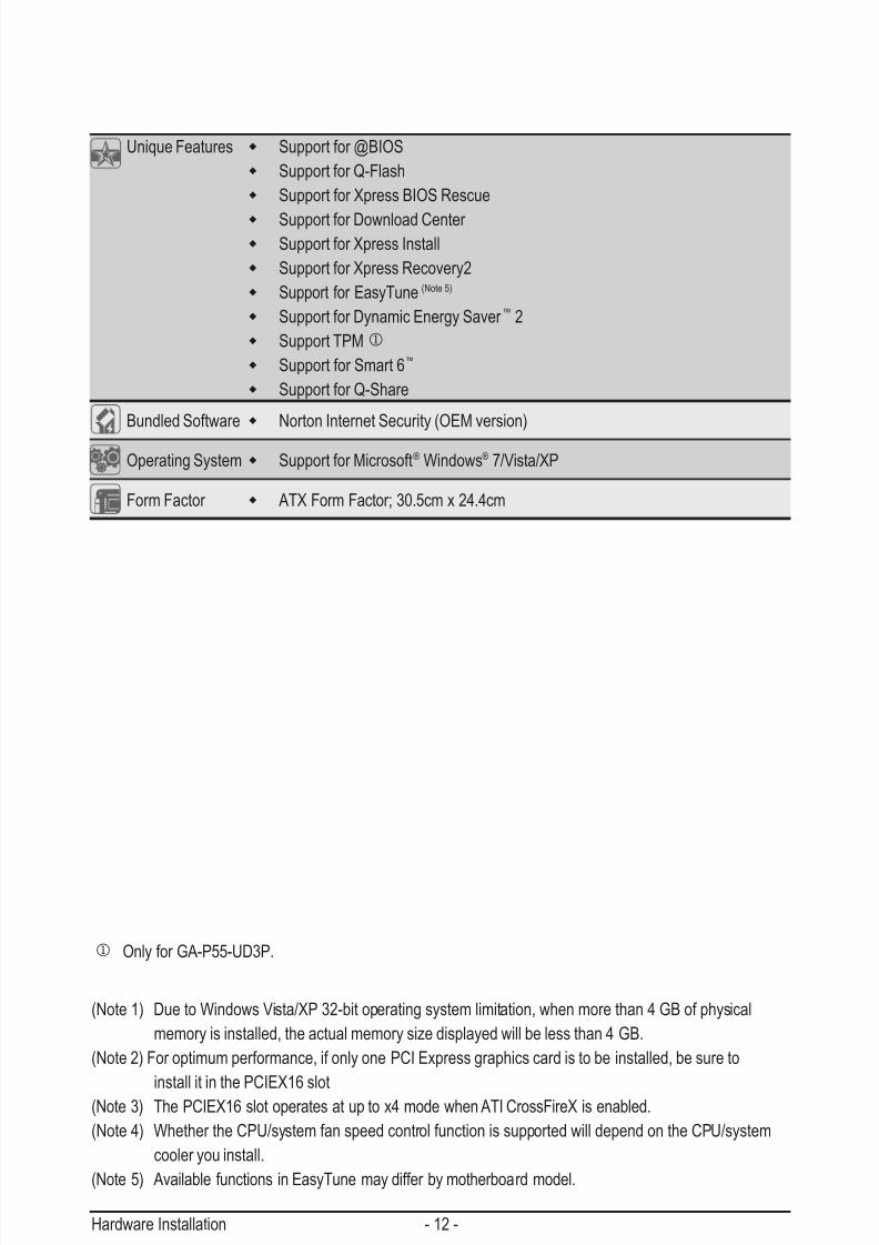
(Note 1) Due to Windows Vista/XP 32-bit operating system limitation, when more than 4 GB of physical
memory is installed, the actual memory size displayed will be less than 4 GB.
(Note 2) For optimum performance, if only one PCI Express graphics card is to be installed, be sure to
install it in the PCIEX16 slot
(Note 3) The PCIEX16 slot operates at up to x4 mode when ATI CrossFireX is enabled.
(Note 4) Whether the CPU/system fan speed control function is supported will depend on the CPU/system
cooler you install.
(Note 5) Available functions in EasyTune may differ by motherboard model.
Unique Features Support for @BIOS
Support for Q-Flash
Support for Xpress BIOS Rescue
Support for Download Center Support for Xpress Install
Support for Xpress Recovery2
Support for EasyTune (Note 5)
Support for Dynamic Energy Saver ™ 2
Support TPMj
Support for Smart 6™
Support for Q-Share
Bundled Software Norton Internet Security (OEM version)
Operating System Support for Microsoft® Windows® 7/Vista/XP
Form Factor ATX Form Factor; 30.5cm x 24.4cm
j Only for GA-P55-UD3P.

7/29/2019 GA-P55-UD3 Manual
http://slidepdf.com/reader/full/ga-p55-ud3-manual 13/128
- 13 - Hardware Installation
1-3 Installing the CPU and CPU Cooler
1-3-1 Installing the CPU
A. Locate the alignment keys on the motherboard CPU socket and the notches on the CPU.
Read the following guidelines before you begin to install the CPU:
• Make sure that the motherboard supports the CPU.
(Go to GIGABYTE's website for the latest CPU support list.)
• Always turn off the computer and unplug the power cord from the power outlet before installingthe CPU to prevent hardware damage.
• Locate the pin one of the CPU. The CPU cannot be inserted if oriented incorrectly. (Or you may
locate the notches on both sides of the CPU and alignment keys on the CPU socket.)
• Apply an even and thin layer of thermal grease on the surface of the CPU.
• Do not turn on the computer if the CPU cooler is not installed, otherwise overheating and dam-
age of the CPU may occur.
• SettheCPUhostfrequencyinaccordancewiththeCPUspecications.Itisnotrecommended
thatthesystembusfrequencybesetbeyondhardwarespecicationssinceitdoesnotmeetthe
standard requirements for the peripherals. If you wish to set the frequency beyond the standardspecications,pleasedosoaccordingtoyourhardwarespecicationsincludingtheCPU,graph-
ics card, memory, hard drive, etc.
NotchNotch
Alignment Key Alignment Key
LGA1156 CPU
LGA1156 CPU Socket
Pin One Corner of the CPU Socket
Triangle Pin One Marking on the CPU

7/29/2019 GA-P55-UD3 Manual
http://slidepdf.com/reader/full/ga-p55-ud3-manual 14/128
Hardware Installation - 14 -
Step 1:
Gently press the CPU socket lever handle down
andawayfromthesocketwithyournger.Thencompletely lift the CPU socket lever and the metal
load plate will be lifted as well.
Step 3:
HoldtheCPUwithyourthumbandindexngers.
Align the CPU pin one marking (triangle) with the
pin one corner of the CPU socket (or you may
align the CPU notches with the socket alignment
keys) and gently insert the CPU into position.
Step 5:
Push the CPU socket lever back into its locked
position.
Step 2:
Use your thumb and index finger to grasp the
protective socket cover as indicated and lift itup vertically. (DO NOT touch socket contacts.
To protect the CPU socket, always replace the
protective socket cover when the CPU is not
installed.)
Step 4:
Once the CPU is properly inserted, use one
hand to hold the socket lever and use the other
to lightly replace the load plate. When replacing
the load plate, make sure the front end of the
load plate is under the shoulder screw.
B. Follow the steps below to correctly install the CPU into the motherboard CPU socket.
Before installing the CPU, make sure to turn off the computer and unplug the power cord from
the power outlet to prevent damage to the CPU.
NOTE:
Hold the CPU socket lever by the handle, not the
lever base portion.

7/29/2019 GA-P55-UD3 Manual
http://slidepdf.com/reader/full/ga-p55-ud3-manual 15/128
- 15 - Hardware Installation
1-3-2 Installing the CPU Cooler
Follow the steps below to correctly install the CPU cooler on the motherboard. (The following procedure uses
Intel® boxed cooler as the example cooler.)
Step 1:
Apply an even and thin layer of thermal grease
on the surface of the installed CPU.
Male Push
Pin
FemalePush Pin
The Topof FemalePush Pin
Direction of the Arrow Sign onthe Male PushPin
Step 2:
Before installing the cooler, note the direction of
the arrow sign on the male push pin. (Turn-
ing the push pin along the direction of arrow is to
remove the cooler, on the contrary, is to install.)
Step 3:
Place the cooler atop the CPU, aligning the four
push pins through the pin holes on the mother-
board. Push down on the push pins diagonally.
Step 4:
You should hear a "click" when pushing down
each push pin. Check that the Male and Female
push pins are joined closely. (Refer to your CPU
cooler installation manual for instructions on
installing the cooler.)
Use extreme care when removing the CPU cooler because the thermal grease/tape between the
CPU cooler and CPU may adhere to the CPU. Inadequately removing the CPU cooler may damage
the CPU.
Step 5:
After the installation, check the back of the moth-
erboard. If the push pin is inserted as the picture
above shows, the installation is complete.
Step 6:
Finally, attach the power connector of the CPU
cooler to the CPU fan header (CPU_FAN) on the
motherboard.

7/29/2019 GA-P55-UD3 Manual
http://slidepdf.com/reader/full/ga-p55-ud3-manual 16/128
Hardware Installation - 16 -
1-4-1 Dual Channel Memory Conguration
This motherboard provides four DDR3 memory sockets and supports Dual Channel Technology. After the
memoryisinstalled,theBIOSwillautomaticallydetectthespecicationsandcapacityofthememory.En-
abling Dual Channel memory mode will double the original memory bandwidth.
The four DDR3 memory sockets are divided into two channels and each channel has two memory sockets as
following:
Channel 0: DDR3_1, DDR3_2
Channel 1: DDR3_3, DDR3_4
1-4 Installing the MemoryRead the following guidelines before you begin to install the memory:
• Make sure that the motherboard supports the memory. It is recommended that memory of the
same capacity, brand, speed, and chips be used.
(Go to GIGABYTE's website for the latest memory support list.)
• Always turn off the computer and unplug the power cord from the power outlet before installing
the memory to prevent hardware damage.
• Memory modules have a foolproof design. A memory module can be installed in only one direc-
tion. If you are unable to insert the memory, switch the direction.
D D R 3
_ 2
D D R 3
_ 1
D D R 3
_ 4
D D R 3
_ 3
If only one DDR3 memory module is installed, it is recommended to install it in the DDR3_1 or
DDR3_3 sockets.
DualChannelMemoryCongurationsTable
(SS=Single-Sided, DS=Double-Sided, "- -"=No Memory)
Due to CPU limitations, read the following guidelines before installing the memory in Dual Channel mode.1. Dual Channel mode cannot be enabled if only one DDR3 memory module is installed.
2. When enabling Dual Channel mode with two or four memory modules, it is recommended that
memory of the same capacity, brand, speed, and chips be used for optimum performance. When
enabling Dual Channel mode with two memory modules, be sure to install them in the DDR3_1 and
DDR3_3 sockets.
DDR3_2 DDR3_1 DDR3_4 DDR3_3
- - DS/SS - - DS/SS
DS/SS DS/SS DS/SS DS/SS
Two Modules
Four Modules

7/29/2019 GA-P55-UD3 Manual
http://slidepdf.com/reader/full/ga-p55-ud3-manual 17/128
- 17 - Hardware Installation
1-4-2 Installing a Memory
Notch
DDR3 DIMM
Before installing a memory module, make sure to turn off the computer and unplug the power
cord from the power outlet to prevent damage to the memory module.
DDR3 and DDR2 DIMMs are not compatible to each other or DDR DIMMs. Be sure to install
DDR3 DIMMs on this motherboard.
ADDR3memorymodulehasanotch,soit canonlytinonedirection.Follow thestepsbelowtocorrectly
install your memory modules in the memory sockets.
Step 1:
Note the orientation of the memory module. Spread the retaining
clips at both ends of the memory socket. Place the memory module
onthesocket.Asindicatedinthepictureontheleft,placeyourn -
gers on the top edge of the memory, push down on the memory and
insert it vertically into the memory socket.
Step 2:
The clips at both ends of the socket will snap into place when the
memory module is securely inserted.

7/29/2019 GA-P55-UD3 Manual
http://slidepdf.com/reader/full/ga-p55-ud3-manual 18/128
Hardware Installation - 18 -
1-5 Installing an Expansion Card
Follow the steps below to correctly install your expansion card in the expansion slot.
1. Locate an expansion slot that supports your card. Remove the metal slot cover from the chassis back panel.
2. Align the card with the slot, and press down on the card until it is fully seated in the slot.
3. Make sure the metal contacts on the card are completely inserted into the slot.
4. Secure the card’s metal bracket to the chassis back panel with a screw.
5. After installing all expansion cards, replace the chassis cover(s).
6. Turn on your computer. If necessary, go to BIOS Setup to make any required BIOS changes for your
expansion card(s).
7. Install the driver provided with the expansion card in your operating system.
Example: Installing and Removing a PCI Express Graphics Card:
• Installing a Graphics Card:
Gently push down on the top edge of the card until
it is fully inserted into the PCI Express slot. Make
sure the card is securely seated in the slot anddoes not rock.
• Removing the Card:
Press the white latch at the end of the PCI Express slot to release the card and
then pull the card straight up from the slot.
Read the following guidelines before you begin to install an expansion card:
• Make sure the motherboard supports the expansion card. Carefully read the manual that came
with your expansion card.
• Always turn off the computer and unplug the power cord from the power outlet before installingan expansion card to prevent hardware damage.
PCI Slot
PCI Express x1 Slot
PCI Express x16 Slot
7/29/2019 GA-P55-UD3 Manual
http://slidepdf.com/reader/full/ga-p55-ud3-manual 19/128
- 19 - Hardware Installation
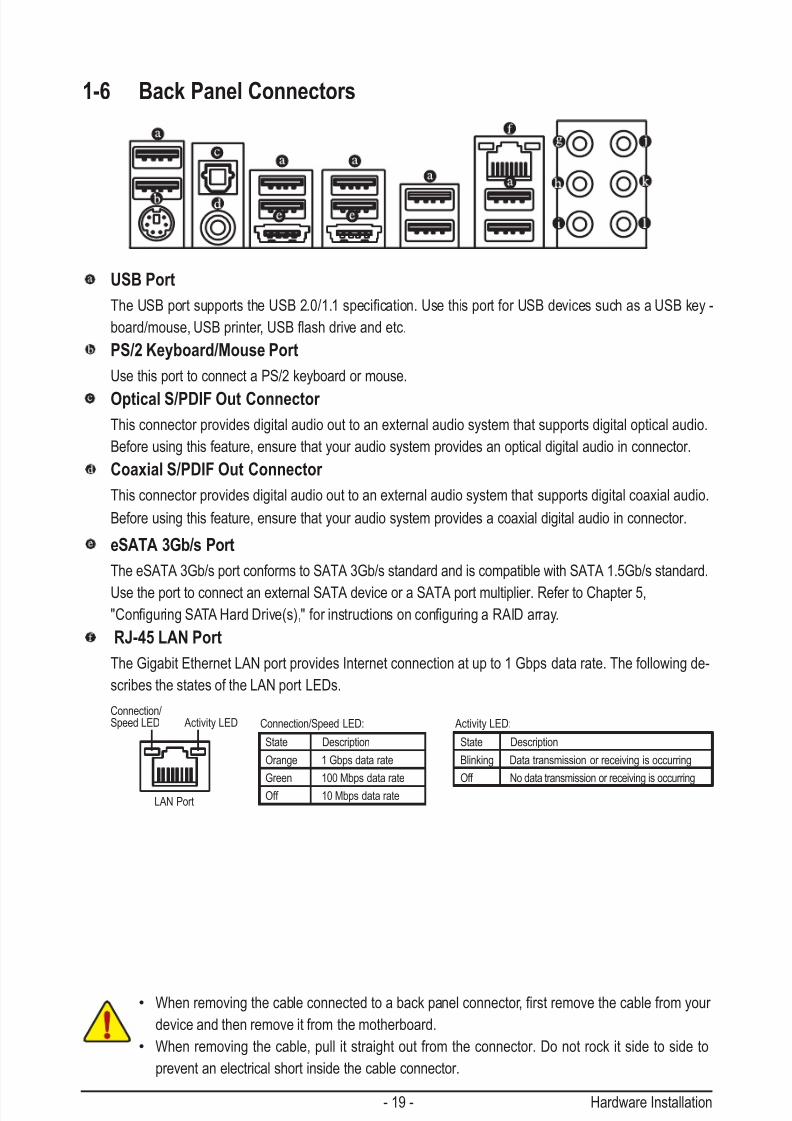
1-6 Back Panel Connectors
USB Port
TheUSBportsupportstheUSB2.0/1.1specication.UsethisportforUSBdevicessuchasaUSBkey-
board/mouse,USBprinter,USBashdriveandetc.
PS/2 Keyboard/Mouse Port
Use this port to connect a PS/2 keyboard or mouse.
Optical S/PDIF Out Connector
This connector provides digital audio out to an external audio system that supports digital optical audio.
Before using this feature, ensure that your audio system provides an optical digital audio in connector.
Coaxial S/PDIF Out Connector
This connector provides digital audio out to an external audio system that supports digital coaxial audio.
Before using this feature, ensure that your audio system provides a coaxial digital audio in connector.
eSATA 3Gb/s Port
The eSATA 3Gb/s port conforms to SATA 3Gb/s standard and is compatible with SATA 1.5Gb/s standard.
Use the port to connect an external SATA device or a SATA port multiplier. Refer to Chapter 5, "ConguringSATAHardDrive(s),"forinstructionsonconguringaRAIDarray.
RJ-45 LAN Port
The Gigabit Ethernet LAN port provides Internet connection at up to 1 Gbps data rate. The following de-
scribes the states of the LAN port LEDs.
Activity LED:
State Description
Blinking Data transmission or receiving is occurring
Off No data transmission or receiving is occurring
Connection/Speed LED:
State Description
Orange 1 Gbps data rate
Green 100 Mbps data rate
Off 10 Mbps data rate
Activity LEDConnection/Speed LED
LAN Port
• Whenremovingthecableconnectedtoabackpanelconnector,rstremovethecablefromyour
device and then remove it from the motherboard.
• When removing the cable, pull it straight out from the connector. Do not rock it side to side to
prevent an electrical short inside the cable connector.

7/29/2019 GA-P55-UD3 Manual
http://slidepdf.com/reader/full/ga-p55-ud3-manual 20/128
Hardware Installation - 20 -
Center/Subwoofer Speaker Out Jack (Orange)
Usethisaudiojacktoconnectcenter/subwooferspeakersina5.1/7.1-channelaudioconguration.
Rear Speaker Out Jack (Black)
Usethisaudiojacktoconnectrearspeakersina4/5.1/7.1-channelaudioconguration.
Side Speaker Out Jack (Gray)
Usethisaudiojacktoconnectsidespeakersina7.1-channelaudioconguration.
Line In Jack (Blue)
The default line in jack. Use this audio jack for line in devices such as an optical drive, walkman, etc.
Line Out Jack (Green)
The default line out jack. Use this audio jack for a headphone or 2-channel speaker. This jack can be
usedtoconnectfrontspeakersina4/5.1/7.1-channelaudioconguration.
Mic In Jack (Pink)
The default Mic in jack. Microphones must be connected to this jack.
In addition to the default speakers settings, the ~ audiojackscanbereconguredtoperform
different functions via the audio software. Only microphones still MUST be connected to the
default Mic in jack ( ). Refer to the instructions on setting up a 2/4/5.1/7.1-channel audio con-
gurationinChapter5,"Conguring2/4/5.1/7.1-ChannelAudio."

7/29/2019 GA-P55-UD3 Manual
http://slidepdf.com/reader/full/ga-p55-ud3-manual 21/128
- 21 - Hardware Installation
1-7 Internal Connectors
Read the following guidelines before connecting external devices:
• First make sure your devices are compliant with the connectors you wish to connect.• Before installing the devices, be sure to turn off the devices and your computer. Unplug the
power cord from the power outlet to prevent damage to the devices.
• After installing the device and before turning on the computer, make sure the device cable has
been securely attached to the connector on the motherboard.
1
2
3
5
7
9
19
617 16
14
13
15
8
4
12
1) ATX_12V_2X4
2) ATX
3) CPU_FAN
4) SYS_FAN1/2
5) PWR_FAN
6) FDD
7) IDE8) SATA2_0/1/2/3/4/5
9) GSATA2_0/1
10) BAT
11) F_PANEL
12) F_AUDIO
13) CD_IN
14) SPDIF_I
15) SPDIF_O
16) F_USB1/F_USB2
17) LPT18) COMA
19) CLR_CMOS
20) PHASE_LED
4
18
20
11
10

7/29/2019 GA-P55-UD3 Manual
http://slidepdf.com/reader/full/ga-p55-ud3-manual 22/128
Hardware Installation - 22 -
ATX_12V_2X4:
ATX_12V_2X4
5
8
1
4
131
2412
ATX
ATX:
PinNo. Denition
13 3.3V14 -12V
15 GND
16 PS_ON (soft On/Off)
17 GND
18 GND
19 GND
20 -5V
21 +5V
22 +5V
23 +5V (Only for 2x12-pin ATX)
24 GND (Only for 2x12-pin ATX)
PinNo. Denition
1 3.3V2 3.3V
3 GND
4 +5V
5 GND
6 +5V
7 GND
8 Power Good
9 5VSB (stand by +5V)
10 +12V
11 +12V (Only for 2x12-pin ATX)
12 3.3V (Only for 2x12-pin ATX)
1/2) ATX_12V_2X4/ATX (2x4 12V Power Connector and 2x12 Main Power Connector)
With the use of the power connector, the power supply can supply enough stable power to all the com-
ponentsonthemotherboard.Beforeconnectingthepowerconnector,rstmakesurethepowersupply
is turned off and all devices are properly installed. The power connector possesses a foolproof design.
Connect the power supply cable to the power connector in the correct orientation. The 12V power con-
nector mainly supplies power to the CPU. If the 12V power connector is not connected, the computer will
not start.
• Use of a power supply providing a 2x4 12V power connector is recommended by the CPU
manufacturer when using an Intel Extreme Edition CPU (130W).
• To meet expansion requirements, it is recommended that a power supply that can withstand
high power consumption be used (500W or greater). If a power supply is used that does not
provide the required power, the result can lead to an unstable or unbootable system.
• The power connectors are compatible with power supplies with 2x2 12V and 2x10 power
connectors. When using a power supply providing a 2x4 12V and a 2x12 power connector,
remove the protective covers from the 12V power connector and the main power connector on
the motherboard. Do not insert the power supply cables into pins under the protective covers
when using a power supply providing a 2x2 12V and a 2x10 power connector.
PinNo. Denition
1 GND (Only for 2x4-pin 12V)
2 GND (Only for 2x4-pin 12V)
3 GND
4 GND
5 +12V (Only for 2x4-pin 12V)6 +12V (Only for 2x4-pin 12V)
7 +12V
8 +12V
7/29/2019 GA-P55-UD3 Manual
http://slidepdf.com/reader/full/ga-p55-ud3-manual 23/128
- 23 - Hardware Installation
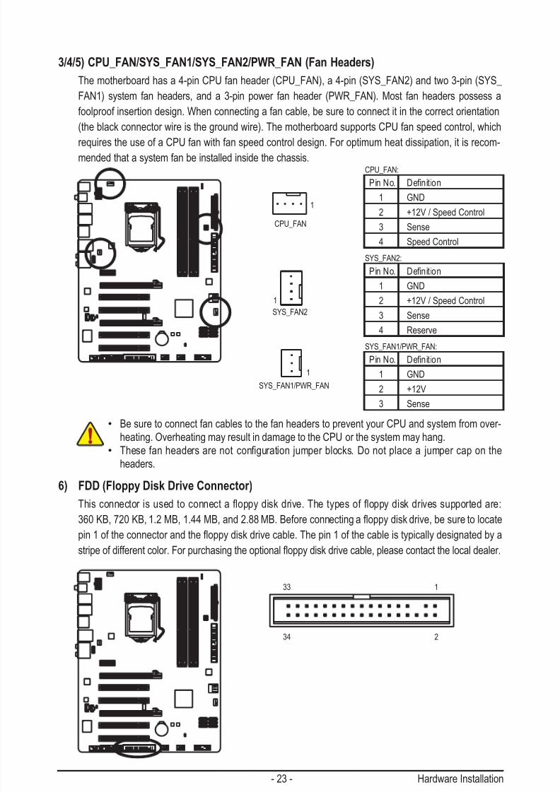
3/4/5) CPU_FAN/SYS_FAN1/SYS_FAN2/PWR_FAN (Fan Headers)
The motherboard has a 4-pin CPU fan header (CPU_FAN), a 4-pin (SYS_FAN2) and two 3-pin (SYS_
FAN1) system fan headers, and a 3-pin power fan header (PWR_FAN). Most fan headers possess a
foolproof insertion design. When connecting a fan cable, be sure to connect it in the correct orientation
(the black connector wire is the ground wire). The motherboard supports CPU fan speed control, which
requires the use of a CPU fan with fan speed control design. For optimum heat dissipation, it is recom-
mended that a system fan be installed inside the chassis.
• Be sure to connect fan cables to the fan headers to prevent your CPU and system from over-
heating. Overheating may result in damage to the CPU or the system may hang.
• Thesefanheadersarenotconguration jumperblocks.Donotplacea jumper caponthe
headers.
CPU_FAN:
PinNo. Denition
1 GND
2 +12V / Speed Control
3 Sense
4 Speed Control
SYS_FAN2:
PinNo. Denition
1 GND
2 +12V / Speed Control
3 Sense
4 Reserve
SYS_FAN1/PWR_FAN:
PinNo. Denition
1 GND
2 +12V
3 Sense
1
CPU_FAN
SYS_FAN2
SYS_FAN1/PWR_FAN
1
1
6) FDD (Floppy Disk Drive Connector)
Thisconnectorisusedtoconnectaoppydiskdrive.Thetypesof oppydiskdrivessupportedare:
360KB,720KB,1.2MB,1.44MB,and2.88MB.Beforeconnectingaoppydiskdrive,besuretolocate
pin1oftheconnectorandtheoppydiskdrivecable.Thepin1ofthecableistypicallydesignatedbya
stripeofdifferentcolor.Forpurchasingtheoptionaloppydiskdrivecable,pleasecontactthelocaldealer.
1
2
33
34
7/29/2019 GA-P55-UD3 Manual
http://slidepdf.com/reader/full/ga-p55-ud3-manual 24/128
Hardware Installation - 24 -
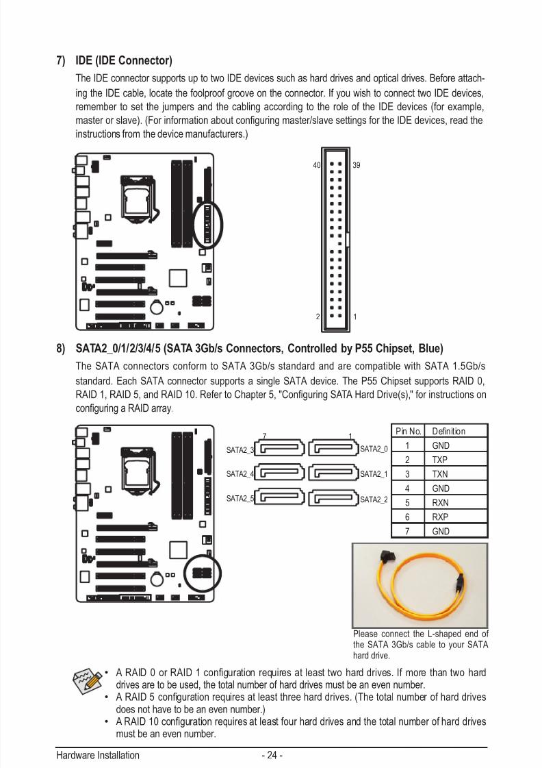
7) IDE (IDE Connector)
The IDE connector supports up to two IDE devices such as hard drives and optical drives. Before attach-
ing the IDE cable, locate the foolproof groove on the connector. If you wish to connect two IDE devices,
remember to set the jumpers and the cabling according to the role of the IDE devices (for example,
masterorslave).(Forinformationaboutconguringmaster/slavesettingsfortheIDEdevices,readthe
instructions from the device manufacturers.)
2
40
1
39
8) SATA2_0/1/2/3/4/5 (SATA 3Gb/s Connectors, Controlled by P55 Chipset, Blue)
The SATA connectors conform to SATA 3Gb/s standard and are compatible with SATA 1.5Gb/s
standard. Each SATA connector supports a single SATA device. The P55 Chipset supports RAID 0,
RAID1,RAID5,andRAID10.RefertoChapter5,"ConguringSATAHardDrive(s),"forinstructionson
conguringaRAIDarray.
PinNo. Denition
1 GND
2 TXP
3 TXN
4 GND
5 RXN
6 RXP
7 GND
SATA2_0
SATA2_2
SATA2_4 SATA2_1
SATA2_3
SATA2_5
17
• ARAID0orRAID 1conguration requires atleasttwoharddrives.Ifmore thantwoharddrives are to be used, the total number of hard drives must be an even number.
• ARAID5conguration requiresatleastthreeharddrives.(Thetotalnumberofharddrivesdoes not have to be an even number.)
• ARAID10congurationrequiresatleastfourharddrivesandthetotalnumberofharddrivesmust be an even number.
Please connect the L-shaped end of the SATA 3Gb/s cable to your SATAhard drive.

7/29/2019 GA-P55-UD3 Manual
http://slidepdf.com/reader/full/ga-p55-ud3-manual 25/128
- 25 - Hardware Installation
7 1
7 1
GSATA2_0
GSATA2_1
9) GSATA2_0/1 (SATA 3Gb/s Connectors, Controlled by GIGABYTE SATA2, White)
The SATA connectors conform to SATA 3Gb/s standard and are compatible with SATA 1.5Gb/s standard.
Each SATA connector supports a single SATA device. The GIGABYTE SATA2 controller supports RAID 0,
RAID1,andJBOD.RefertoChapter5,"ConguringSATAHardDrive(s),"forinstructionsonconguring
a RAID array.
PinNo. Denition
1 GND
2 TXP
3 TXN
4 GND
5 RXN
6 RXP
7 GND
ARAID0orRAID1congurationrequiresatleasttwohard
drives. If more than two hard drives are to be used, the total
number of hard drives must be an even number.
Please connect the L-shaped end of
the SATA 3Gb/s cable to your SATA
hard drive.
10) BAT (BATTERY)
Thebatteryprovidespowertokeepthevalues(suchasBIOScongurations,date,andtimeinformation)
in the CMOS when the computer is turned off. Replace the battery when the battery voltage drops to a
low level, or the CMOS values may not be accurate or may be lost.
You may clear the CMOS values by removing the battery:1. Turn off your computer and unplug the power cord.
2. Gently remove the battery from the battery holder and wait for one minute.
(Or use a metal object like a screwdriver to touch the positive and negative
terminals of the battery holder, making them short for 5 seconds.)
3. Replace the battery.
4. Plug in the power cord and restart your computer.
• Always turn off your computer and unplug the power cord before replacing the battery.
• Replace the battery with an equivalent one. Danger of explosion if the battery is replaced with an
incorrect model.
• Contact the place of purchase or local dealer if you are not able to replace the battery by yourself or uncertain about the battery model.
• When installing the battery, note the orientation of the positive side (+) and the negative side (-) of the
battery (the positive side should face up).
• Used batteries must be handled in accordance with local environmental regulations.

7/29/2019 GA-P55-UD3 Manual
http://slidepdf.com/reader/full/ga-p55-ud3-manual 26/128
Hardware Installation - 26 -
11) F_PANEL (Front Panel Header)
Connect the power switch, reset switch, speaker, chassis intrusion switch/sensor and system status
indicator on the chassis to this header according to the pin assignments below. Note the positive and
negative pins before connecting the cables.
• PW (Power Switch, Red): Connectstothepowerswitchonthechassisfrontpanel.Youmaycongurethewaytoturnoffyour
system using the power switch (refer to Chapter 2, "BIOS Setup," "Power Management Setup," for
more information).
• SPEAK (Speaker, Orange):
Connects to the speaker on the chassis front panel. The system reports system startup status by is-
suing a beep code. One single short beep will be heard if no problem is detected at system startup. If
a problem is detected, the BIOS may issue beeps in different patterns to indicate the problem. Refer
to Chapter 5, "Troubleshooting," for information about beep codes.
• HD (Hard Drive Activity LED, Blue)Connects to the hard drive activity LED on the chassis front panel. The LED is on when the hard drive
is reading or writing data.
• RES (Reset Switch, Green):
Connects to the reset switch on the chassis front panel. Press the reset switch to restart the computer
if the computer freezes and fails to perform a normal restart.
• CI (Chassis Intrusion Header, Gray):
Connects to the chassis intrusion switch/sensor on the chassis that can detect if the chassis cover
has been removed. This function requires a chassis with a chassis intrusion switch/sensor.
• MSG/PWR (Message/Power/Sleep LED, Yellow/Purple):
Connects to the power status indicator on the chassis front panel. The LED
is on when the system is operating. The LED keeps blinking when the sys-
tem is in S1 sleep state. The LED is off when the system is in S3/S4 sleep
state or powered off (S5).
System Status LED
S0 On
S1 Blinking
S3/S4/S5 Off
The front panel design may differ by chassis. A front panel module mainly consists of power
switch, reset switch, power LED, hard drive activity LED, speaker and etc. When connecting your
chassis front panel module to this header, make sure the wire assignments and the pin assign-
ments are matched correctly.
Power LED
1
2
19
20
C I -
C I +
P W R -
P W R +
M S G -
P W -
S P E A K +
S P E A K -
M S G +
P W +
Message/Power/
Sleep LED Speaker Power
Switch
H D -
R E S +
H D +
R E S -
Hard Drive Activity LED
ResetSwitch
Chassis Intrusion
Header
7/29/2019 GA-P55-UD3 Manual
http://slidepdf.com/reader/full/ga-p55-ud3-manual 27/128
- 27 - Hardware Installation
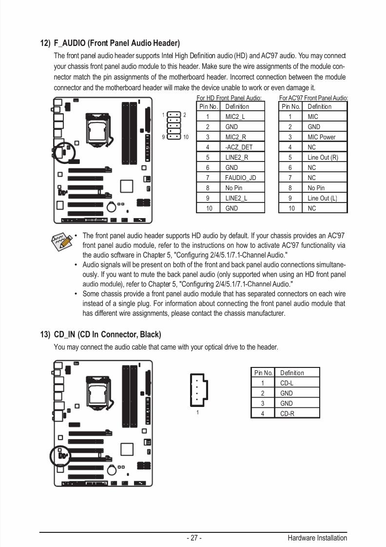
12) F_AUDIO (Front Panel Audio Header)
ThefrontpanelaudioheadersupportsIntelHighDenitionaudio(HD)andAC'97audio.Youmayconnect
your chassis front panel audio module to this header. Make sure the wire assignments of the module con-
nector match the pin assignments of the motherboard header. Incorrect connection between the module
connector and the motherboard header will make the device unable to work or even damage it.
PinNo. Denition
1 MIC2_L
2 GND
3 MIC2_R
4 -ACZ_DET
5 LINE2_R
6 GND
7 FAUDIO_JD
8 No Pin
9 LINE2_L
10 GND
PinNo. Denition
1 MIC
2 GND
3 MIC Power
4 NC
5 Line Out (R)
6 NC
7 NC
8 No Pin
9 Line Out (L)
10 NC
For HD Front Panel Audio: For AC'97 Front Panel Audio:
1 2
9 10
• The front panel audio header supports HD audio by default. If your chassis provides an AC'97
front panel audio module, refer to the instructions on how to activate AC'97 functionality via
theaudiosoftwareinChapter5,"Conguring2/4/5.1/7.1-ChannelAudio."
• Audio signals will be present on both of the front and back panel audio connections simultane-
ously. If you want to mute the back panel audio (only supported when using an HD front panel
audiomodule),refertoChapter5,"Conguring2/4/5.1/7.1-ChannelAudio."• Some chassis provide a front panel audio module that has separated connectors on each wire
instead of a single plug. For information about connecting the front panel audio module that
has different wire assignments, please contact the chassis manufacturer.
13) CD_IN (CD In Connector, Black)
You may connect the audio cable that came with your optical drive to the header.
PinNo. Denition
1 CD-L2 GND
3 GND
4 CD-R1

7/29/2019 GA-P55-UD3 Manual
http://slidepdf.com/reader/full/ga-p55-ud3-manual 28/128
Hardware Installation - 28 -
14) SPDIF_I (S/PDIF In Header, White)
This header supports digital S/PDIF In and can connect to an audio device that supports digital audio out
via an optional S/PDIF In cable. For purchasing the optional S/PDIF In cable, please contact the local
dealer.
PinNo. Denition
1 Power
2 SPDIFI
3 GND
PinNo. Denition1 SPDIFO
2 GND
15) SPDIF_O (S/PDIF Out Header)
This header supports digital S/PDIF Out and connects a S/PDIF digital audio cable (provided by expan-
sion cards) for digital audio output from your motherboard to certain expansion cards like graphics cards
and sound cards. For example, some graphics cards may require you to use a S/PDIF digital audio cable
for digital audio output from your motherboard to your graphics card if you wish to connect an HDMI
display to the graphics card and have digital audio output from the HDMI display at the same time. For
information about connecting the S/PDIF digital audio cable, carefully read the manual for your expan-
sion card.
1
1

7/29/2019 GA-P55-UD3 Manual
http://slidepdf.com/reader/full/ga-p55-ud3-manual 29/128
- 29 - Hardware Installation
16) F_USB1/F_USB2 (USB Headers, Blue)
TheheadersconformtoUSB2.0/1.1specication.EachUSBheadercanprovidetwoUSBportsviaan
optional USB bracket. For purchasing the optional USB bracket, please contact the local dealer.
10
9
2
1
PinNo. Denition
1 Power (5V)2 Power (5V)
3 USB DX-
4 USB DY-
5 USB DX+
6 USB DY+
7 GND
8 GND
9 No Pin
10 NC
• Do not plug the IEEE 1394 bracket (2x5-pin) cable into the USB header.
• Prior to installing the USB bracket, be sure to turn off your computer and unplug the power
cord from the power outlet to prevent damage to the USB bracket.
17) LPT (Parallel Port Header)
The LPT header can provide one parallel port via an optional LPT port cable. For purchasing the optionalLPT port cable, please contact the local dealer.
26
25
2
1
PinNo. Denition
14 GND
15 PD6
16 GND
17 PD7
18 GND
19 ACK-
20 GND
21 BUSY
22 GND
23 PE
24 No Pin
25 SLCT26 GND
PinNo. Denition
1 STB-
2 AFD-
3 PD0
4 ERR-
5 PD1
6 INIT-
7 PD2
8 SLIN-
9 PD3
10 GND
11 PD4
12 GND13 PD5

7/29/2019 GA-P55-UD3 Manual
http://slidepdf.com/reader/full/ga-p55-ud3-manual 30/128
Hardware Installation - 30 -
18) COMA (Serial Port Header, White)
The COMA header can provide one serial port via an optional COM port cable. For purchasing the op-
tional COM port cable, please contact the local dealer.
10
9
2
1
PinNo. Denition
1 NDCD-
2 NSIN
3 NSOUT
4 NDTR-
5 GND
6 NDSR-
7 NRTS-
8 NCTS-
9 NRI-10 No Pin
19) CLR_CMOS (Clearing CMOS Jumper)
Usethisjumpertoclear theCMOSvalues(e.g.date informationandBIOScongurations) andreset
the CMOS values to factory defaults. To clear the CMOS values, place a jumper cap on the two pins totemporarily short the two pins or use a metal object like a screwdriver to touch the two pins for a few
seconds.
Open: Normal
Short: Clear CMOS Values
• Always turn off your computer and unplug the power cord from
the power outlet before clearing the CMOS values.
• After clearing the CMOS values and before turning on your
computer, be sure to remove the jumper cap from the jumper.
Failure to do so may cause damage to the motherboard.
• After system restart, go to BIOS Setup to
load factory defaults (select Load Optimized Defaults) or
manuallyconguretheBIOSsettings(refertoChapter2,"BIOS
Setup,"forBIOScongurations).

7/29/2019 GA-P55-UD3 Manual
http://slidepdf.com/reader/full/ga-p55-ud3-manual 31/128
- 31 - Hardware Installation
20) PHASE LED
The number of lighted LEDs indicates the CPU loading. The higher the CPU loading, the more the
numberoflightedLEDs.ToenablethePhaseLEDdisplayfunction,pleaserstenableDynamicEnergy
Saver ™ 2. Refer to Chapter 4, "Dynamic Energy Saver ™ 2," for more details.

7/29/2019 GA-P55-UD3 Manual
http://slidepdf.com/reader/full/ga-p55-ud3-manual 32/128
Hardware Installation - 32 -

7/29/2019 GA-P55-UD3 Manual
http://slidepdf.com/reader/full/ga-p55-ud3-manual 33/128
- 33 - BIOS Setup
BIOS (Basic Input and Output System) records hardware parameters of the system in the CMOS on the
motherboard. Its major functions include conducting the Power-On Self-Test (POST) during system startup,
saving system parameters and loading operating system, etc. BIOS includes a BIOS Setup program that
allowstheusertomodifybasicsystemcongurationsettingsortoactivatecertainsystemfeatures.When
the power is turned off, the battery on the motherboard supplies the necessary power to the CMOS to keep
thecongurationvaluesintheCMOS.
To access the BIOS Setup program, press the <Delete> key during the POST when the power is turned on.
To see more advanced BIOS Setup menu options, you can press <Ctrl> + <F1> in the main menu of the
BIOS Setup program.
To upgrade the BIOS, use either the GIGABYTE Q-Flash or @BIOS utility.
• Q-Flash allows the user to quickly and easily upgrade or back up BIOS without entering the operating
system.
• @BIOS is a Windows-based utility that searches and downloads the latest version of BIOS from the
Internet and updates the BIOS.
For instructions on using the Q-Flash and @BIOS utilities, refer to Chapter 4, "BIOS Update Utilities."
Chapter 2 BIOS Setup
• BecauseBIOSashing ispotentially risky, ifyoudonotencounterproblemsusing thecurrent
versionofBIOS,itisrecommendedthatyounotashtheBIOS.ToashtheBIOS,doitwith
caution.InadequateBIOSashingmayresultinsystemmalfunction.
• BIOS will emit a beep code during the POST. Refer to Chapter 5, "Troubleshooting," for the beepcodes description.
• It is recommended that you not alter the default settings (unless you need to) to prevent system
instability or other unexpected results. Inadequately altering the settings may result in system's
failure to boot. If this occurs, try to clear the CMOS values and reset the board to default values.
(Refer to the "Load Optimized Defaults" section in this chapter or introductions of the battery/
clearing CMOS jumper in Chapter 1 for how to clear the CMOS values.)

7/29/2019 GA-P55-UD3 Manual
http://slidepdf.com/reader/full/ga-p55-ud3-manual 34/128
BIOS Setup - 34 -
2-1 Startup Screen
The following screens may appear when the computer boots.
A. The LOGO Screen (Default)
B. The POST Screen
Function Keys:
<TAB>: POST SCREEN
Press the <Tab> key to show the BIOS POST screen. To show the BIOS POST screen at system start-
up, refer to the instructions on the Full Screen LOGO Show item on page 50.
<DEL>: BIOS SETUP\Q-FLASH
Press the <Delete> key to enter BIOS Setup or to access the Q-Flash utility in BIOS Setup.
<F9>: XPRESS RECOVERY2
If you have ever entered Xpress Recovery2 to back up hard drive data using the driver disk, the <F9>
key can be used for subsequent access to Xpress Recovery2 during the POST. For more information,
refer to Chapter 4, "Xpress Recovery2."
<F12>: BOOT MENU
BootMenuallowsyoutosettherstbootdevicewithoutenteringBIOSSetup.InBootMenu,usetheup
arrow key <h> or the down arrow key <i>toselecttherstbootdevice,thenpress<Enter>toaccept.
ToexitBootMenu,press<Esc>.ThesystemwilldirectlybootfromthedeviceconguredinBootMenu.
Note: The setting in Boot Menu is effective for one time only. After system restart, the device boot order willstillbebasedonBIOSSetupsettings.YoucanaccessBootMenuagaintochangetherstbootde-
vice setting as needed.
<END>: Q-FLASH
Pressthe<End>keytoaccesstheQ-FlashutilitydirectlywithouthavingtoenterBIOSSetuprst.
Function Keys
Motherboard Model
BIOS Version
Award Modular BIOS v6.00PG, An Energy Star AllyCopyright (C) 1984-2009, Award Software, Inc.
P55-UD3P D6...
.
<DEL>: BIOS Setup <F9>: XpressRecovery2 <F12>: Boot Menu <End>: Qflash07/08/2009-P55-7A89RG0JC-00
Function Keys
7/29/2019 GA-P55-UD3 Manual
http://slidepdf.com/reader/full/ga-p55-ud3-manual 35/128
- 35 - BIOS Setup
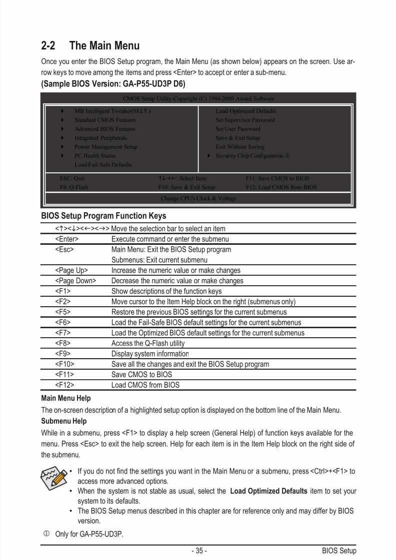
2-2 The Main Menu
Once you enter the BIOS Setup program, the Main Menu (as shown below) appears on the screen. Use ar-
row keys to move among the items and press <Enter> to accept or enter a sub-menu.
(Sample BIOS Version: GA-P55-UD3P D6)
Main Menu Help
The on-screen description of a highlighted setup option is displayed on the bottom line of the Main Menu.
Submenu Help
While in a submenu, press <F1> to display a help screen (General Help) of function keys available for the
menu. Press <Esc> to exit the help screen. Help for each item is in the Item Help block on the right side of
the submenu.
BIOS Setup Program Function Keys
<h><i><f><g> Move the selection bar to select an item
<Enter> Execute command or enter the submenu
<Esc> Main Menu: Exit the BIOS Setup program
Submenus: Exit current submenu
<Page Up> Increase the numeric value or make changes
<Page Down> Decrease the numeric value or make changes
<F1> Show descriptions of the function keys<F2> Move cursor to the Item Help block on the right (submenus only)
<F5> Restore the previous BIOS settings for the current submenus
<F6> Load the Fail-Safe BIOS default settings for the current submenus
<F7> Load the Optimized BIOS default settings for the current submenus
<F8> Access the Q-Flash utility
<F9> Display system information
<F10> Save all the changes and exit the BIOS Setup program
<F11> Save CMOS to BIOS
<F12> Load CMOS from BIOS
• IfyoudonotndthesettingsyouwantintheMainMenuorasubmenu,press<Ctrl>+<F1>to
access more advanced options.
• When the system is not stable as usual, select the Load Optimized Defaults item to set your system to its defaults.
• The BIOS Setup menus described in this chapter are for reference only and may differ by BIOS
version.
CMOS Setup Utility-Copyright (C) 1984-2009 Award Software
Change CPU's Clock & Voltage
MB Intelligent Tweaker(M.I.T.)
Standard CMOS Features
Advanced BIOS Features
Integrated Peripherals
Power Management Setup
PC Health Status
Load Fail-Safe Defaults
Load Optimized Defaults
Set Supervisor Password
Set User Password
Save & Exit Setup
Exit Without Saving
SecurityChipCongurationj
ESC: Quit higf: Select Item F11: Save CMOS to BIOS
F8: Q-Flash F10: Save & Exit Setup F12: Load CMOS from BIOS
j Only for GA-P55-UD3P.

7/29/2019 GA-P55-UD3 Manual
http://slidepdf.com/reader/full/ga-p55-ud3-manual 36/128
BIOS Setup - 36 -
The Functions of the <F11> and <F12> keys (For the Main Menu Only) F11: Save CMOS to BIOS
ThisfunctionallowsyoutosavethecurrentBIOSsettingstoaprole.Youcancreateupto8proles
(Prole1-8)andnameeachprole.Firstentertheprolename(toerasethedefaultprolename,use
the SPACE key) and then press <Enter> to complete.
F12: Load CMOS from BIOSIf your system becomes unstable and you have loaded the BIOS default settings, you can use this
functiontoloadtheBIOSsettingsfromaprolecreatedbefore,withoutthehasslesofreconguringthe
BIOSsettings.Firstselecttheproleyouwishtoload,thenpress<Enter>tocomplete.
MB Intelligent Tweaker(M.I.T.)Usethismenutoconguretheclock,frequencyandvoltagesofyourCPU,memory,etc.
Standard CMOS Features Usethismenutocongurethesystemtimeanddate,harddrivetypes,oppydiskdrivetypes,andthe
type of errors that stop the system boot, etc.
Advanced BIOS Features Usethismenutocongurethedevicebootorder,advancedfeaturesavailableontheCPU,andthepri-
mary display adapter.
Integrated Peripherals Usethismenutocongureallperipheraldevices,suchasIDE,SATA,USB,integratedaudio,andinte-
grated LAN, etc.
Power Management Setup Usethismenutocongureallthepower-savingfunctions.
PC Health Status
Use this menu to see information about autodetected system/CPU temperature, system voltage and fanspeed, etc.
Load Fail-Safe DefaultsFail-Safe defaults are factory settings for the most stable, minimal-performance system operations.
Load Optimized DefaultsOptimized defaults are factory settings for optimal-performance system operations.
Set Supervisor PasswordChange, set, or disable password. It allows you to restrict access to the system and BIOS Setup.
A supervisor password allows you to make changes in BIOS Setup.
Set User PasswordChange, set, or disable password. It allows you to restrict access to the system and BIOS Setup.
A user password only allows you to view the BIOS settings but not to make changes.
Save & Exit SetupSave all the changes made in the BIOS Setup program to the CMOS and exit BIOS Setup. (Pressing
<F10> can also carry out this task.)
Exit Without Saving Abandonallchangesandtheprevioussettingsremainineffect.Pressing<Y>totheconrmationmes-
sage will exit BIOS Setup. (Pressing <Esc> can also carry out this task.)
Security Chip Congurationj UsethismenutoconguretheTPMfunction.
j Only for GA-P55-UD3P.
7/29/2019 GA-P55-UD3 Manual
http://slidepdf.com/reader/full/ga-p55-ud3-manual 37/128
- 37 - BIOS Setup
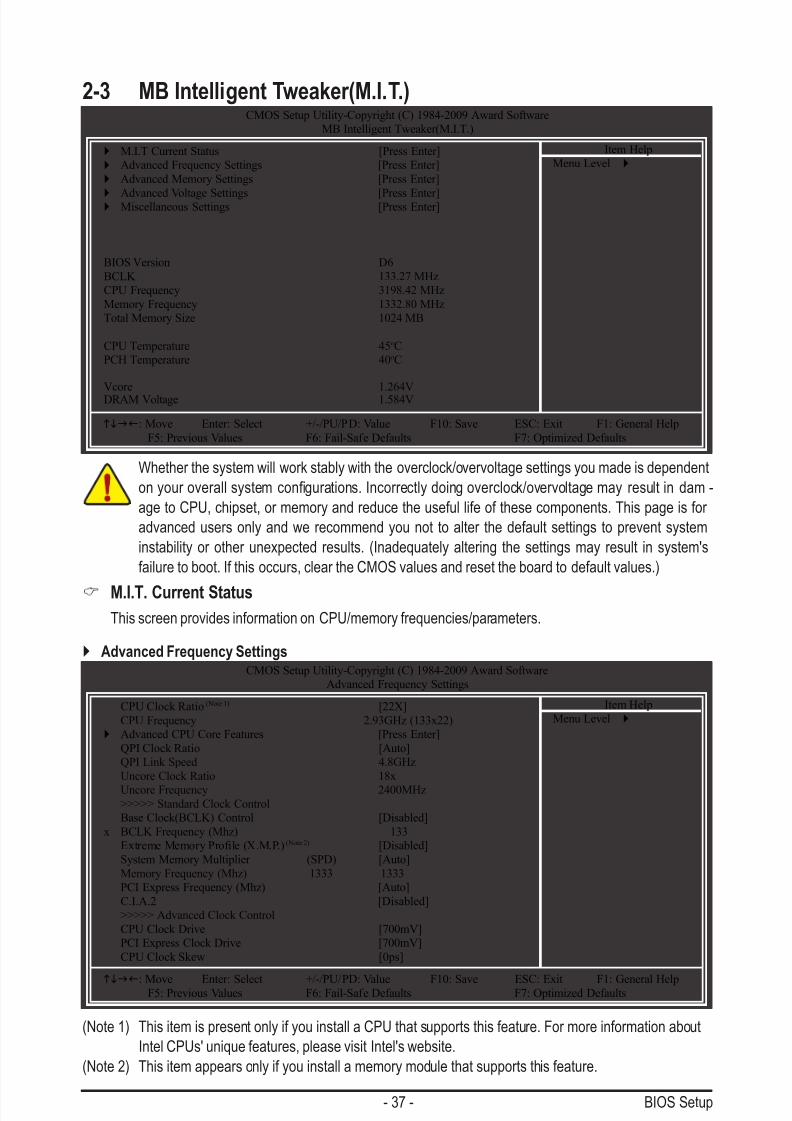
2-3 MB Intelligent Tweaker(M.I.T.)
Whether the system will work stably with the overclock/overvoltage settings you made is dependent
onyouroverallsystemcongurations.Incorrectlydoingoverclock/overvoltagemay resultindam-
age to CPU, chipset, or memory and reduce the useful life of these components. This page is for
advanced users only and we recommend you not to alter the default settings to prevent system
instability or other unexpected results. (Inadequately altering the settings may result in system's
failure to boot. If this occurs, clear the CMOS values and reset the board to default values.)
M.I.T. Current StatusThis screen provides information on CPU/memory frequencies/parameters.
CMOS Setup Utility-Copyright (C) 1984-2009 Award Software
MB Intelligent Tweaker(M.I.T.)
M.I.T Current Status [Press Enter]
Advanced Frequency Settings [Press Enter]
Advanced Memory Settings [Press Enter]
Advanced Voltage Settings [Press Enter] Miscellaneous Settings [Press Enter]
BIOS Version D6
BCLK 133.27 MHz
CPU Frequency 3198.42 MHz
Memory Frequency 1332.80 MHz
Total Memory Size 1024 MB
CPU Temperature 45oC
PCH Temperature 40oC
Vcore 1.264VDRAM Voltage 1.584V
higf: Move Enter: Select +/-/PU/PD: Value F10: Save ESC: Exit F1: General Help
F5: Previous Values F6: Fail-Safe Defaults F7: Optimized Defaults
Item Help
Menu Level
Advanced Frequency Settings
(Note 1) This item is present only if you install a CPU that supports this feature. For more information about
Intel CPUs' unique features, please visit Intel's website.
(Note 2) This item appears only if you install a memory module that supports this feature.
CMOS Setup Utility-Copyright (C) 1984-2009 Award Software
Advanced Frequency Settings
CPU Clock Ratio (Note 1) [22X]
CPU Frequency 2.93GHz (133x22)
Advanced CPU Core Features [Press Enter]
QPI Clock Ratio [Auto]
QPI Link Speed 4.8GHz
Uncore Clock Ratio 18x
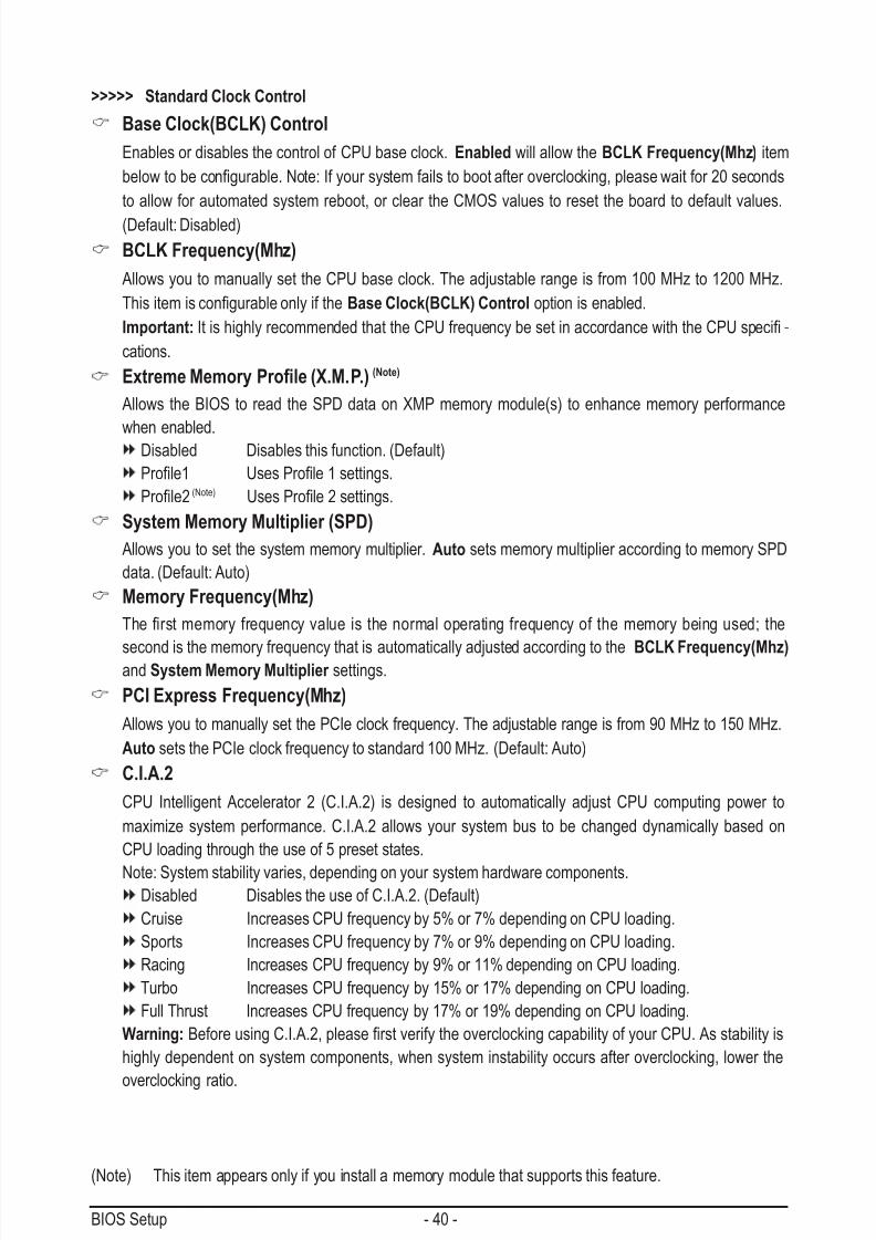
Uncore Frequency 2400MHz>>>>> Standard Clock Control
Base Clock(BCLK) Control [Disabled]
x BCLK Frequency (Mhz) 133
ExtremeMemoryProle(X.M.P.) (Note 2) [Disabled]
System Memory Multiplier (SPD) [Auto]
Memory Frequency (Mhz) 1333 1333
PCI Express Frequency (Mhz) [Auto]
C.I.A.2 [Disabled]
>>>>> Advanced Clock Control
CPU Clock Drive [700mV]
PCI Express Clock Drive [700mV]
CPU Clock Skew [0ps]
higf: Move Enter: Select +/-/PU/PD: Value F10: Save ESC: Exit F1: General HelpF5: Previous Values F6: Fail-Safe Defaults F7: Optimized Defaults
Item Help
Menu Level

7/29/2019 GA-P55-UD3 Manual
http://slidepdf.com/reader/full/ga-p55-ud3-manual 38/128
BIOS Setup - 38 -
CPU Clock Ratio (Note)
Allows you to alter the clock ratio for the installed CPU.
The item is present only if a CPU with unlocked clock ratio is installed.
CPU Frequency
Displays the current operating CPU frequency.
(Note) This item is present only if you install a CPU that supports this feature. For more information about
Intel CPUs' unique features, please visit Intel's website.
CMOS Setup Utility-Copyright (C) 1984-2009 Award Software
Advanced CPU Core Features
higf: Move Enter: Select +/-/PU/PD: Value F10: Save ESC: Exit F1: General Help
F5: Previous Values F6: Fail-Safe Defaults F7: Optimized Defaults
Item Help
Menu LevelIntel(R) Turbo Boost Tech. [Enabled]
CPU Cores Enabled (Note) [All]
CPU Multi-Threading (Note) [Enabled]
CPU Enhanced Halt (C1E) (Note) [Auto]
C3/C6/C7 State Support (Note) [Auto]
CPU Thermal Monitor (Note) [Auto]
CPU EIST Function
(Note)
[Auto]Bi-Directional PROCHOT (Note) [Auto]
Virtualization Technology (Note) [Enabled]
Advanced CPU Core Features
Intel(R) Turbo Boost Tech.
Allows you to determine whether to enable the Intel CPU Turbo Boost technology. (Default: Enabled)
CPU Cores Enabled (Note)
Allows you to determine whether to enable all CPU cores.
All Enables all CPU cores. (Default)
1 Enables only one CPU core.
2 Enables only two CPU cores.
3 Enables only three CPU cores.CPU Multi-Threading (Note)
Allows you to determine whether to enable multi-threading technology when using an Intel CPU that
supports this function. This feature only works for operating systems that support multi-processor mode.
(Default: Enabled)
CPU Enhanced Halt (C1E) (Note)
Enables or disables Intel CPU Enhanced Halt (C1E) function, a CPU power-saving function in system
halt state. When enabled, the CPU core frequency and voltage will be reduced during system halt state
to decrease power consumption. AutoletstheBIOSautomaticallycongurethissetting.(Default:Auto)
7/29/2019 GA-P55-UD3 Manual
http://slidepdf.com/reader/full/ga-p55-ud3-manual 39/128
- 39 - BIOS Setup
(Note) This item is present only if you install a CPU that supports this feature. For more information about
Intel CPUs' unique features, please visit Intel's website.
C3/C6/C7 State Support (Note)
Allows you to determine whether to let the CPU enter C3/C6/C7 mode in system halt state. When en-
abled, the CPU core frequency and voltage will be reduced during system halt state to decrease power
consumption. The C3/C6/C7 state is a more enhanced power-saving state than C1. Auto lets the BIOS
automaticallycongurethissetting.(Default:Auto)
CPU Thermal Monitor (Note)
Enables or disables Intel CPU Thermal Monitor function, a CPU overheating protection function. When
enabled, the CPU core frequency and voltage will be reduced when the CPU is overheated. Auto lets
theBIOSautomaticallycongurethissetting.(Default:Auto)
CPU EIST Function (Note)
Enables or disables Enhanced Intel SpeedStep Technology (EIST). Depending on CPU loading, Intel
EIST technology can dynamically and effectively lower the CPU voltage and core frequency to decrease
average power consumption and heat production. AutoletstheBIOSautomaticallycongurethisset-
ting. (Default: Auto)
Bi-Directional PROCHOT (Note)
Auto LetsBIOSautomaticallycongurethissetting.(Default)
Enabled When the CPU or chipset detects that an overheating is occurring, PROCHOT signals will
be emitted to lower CPU performance to decrease heat production.
Disabled Only allows the CPU to detect whether an overheating is occurring to emit PROCHOT
signals.
Virtualization Technology (Note)
Enables or disables Intel Virtualization Technology. Virtualization enhanced by Intel Virtualization Tech-
nology will allow a platform to run multiple operating systems and applications in independent partitions.With virtualization, one computer system can function as multiple virtual systems. (Default: Enabled)
QPI Clock Ratio
Allows you to set the QPI clock ratio. Options are: Auto (default), x32, x36. The item is adjustable only if
a CPU with unlocked clock ratio is installed.
QPI Link Speed
Displays the current operating QPI link speed.
Uncore Clock Ratio
DisplaystheUncoreclockratio.(Thisratioisxed.)
Uncore Frequency
This value is determined by multiplying the BLCK Frequency value by the Uncore Clock Ratio value.
7/29/2019 GA-P55-UD3 Manual
http://slidepdf.com/reader/full/ga-p55-ud3-manual 40/128
BIOS Setup - 40 -
(Note) This item appears only if you install a memory module that supports this feature.
>>>>> Standard Clock Control
Base Clock(BCLK) Control
Enables or disables the control of CPU base clock. Enabled will allow the BCLK Frequency(Mhz) item
belowtobecongurable.Note:Ifyoursystemfailstobootafteroverclocking,pleasewaitfor20seconds
to allow for automated system reboot, or clear the CMOS values to reset the board to default values.
(Default: Disabled)
BCLK Frequency(Mhz)
Allows you to manually set the CPU base clock. The adjustable range is from 100 MHz to 1200 MHz.
ThisitemiscongurableonlyiftheBase Clock(BCLK) Control option is enabled.
Important:ItishighlyrecommendedthattheCPUfrequencybesetinaccordancewiththeCPUspeci-
cations.
Extreme Memory Prole (X.M.P.) (Note)
Allows the BIOS to read the SPD data on XMP memory module(s) to enhance memory performance
when enabled.Disabled Disables this function. (Default)
Prole1 UsesProle1settings.
Prole2 (Note) UsesProle2settings.
System Memory Multiplier (SPD)
Allows you to set the system memory multiplier. Auto sets memory multiplier according to memory SPD
data. (Default: Auto)
Memory Frequency(Mhz)
Therstmemory frequencyvalue is thenormal operatingfrequencyofthememorybeingused; the
second is the memory frequency that is automatically adjusted according to the BCLK Frequency(Mhz) and System Memory Multiplier settings.
PCI Express Frequency(Mhz)
Allows you to manually set the PCIe clock frequency. The adjustable range is from 90 MHz to 150 MHz.
Auto sets the PCIe clock frequency to standard 100 MHz. (Default: Auto)
C.I.A.2
CPU Intelligent Accelerator 2 (C.I.A.2) is designed to automatically adjust CPU computing power to
maximize system performance. C.I.A.2 allows your system bus to be changed dynamically based on
CPU loading through the use of 5 preset states.
Note: System stability varies, depending on your system hardware components.Disabled Disables the use of C.I.A.2. (Default)
Cruise Increases CPU frequency by 5% or 7% depending on CPU loading.
Sports Increases CPU frequency by 7% or 9% depending on CPU loading.
Racing Increases CPU frequency by 9% or 11% depending on CPU loading.
Turbo Increases CPU frequency by 15% or 17% depending on CPU loading.
Full Thrust Increases CPU frequency by 17% or 19% depending on CPU loading.
Warning:BeforeusingC.I.A.2,pleaserstverifytheoverclockingcapabilityofyourCPU.Asstabilityis
highly dependent on system components, when system instability occurs after overclocking, lower the
overclocking ratio.

7/29/2019 GA-P55-UD3 Manual
http://slidepdf.com/reader/full/ga-p55-ud3-manual 41/128
- 41 - BIOS Setup
>>>>> Advanced Clock Control
CPU Clock Drive
Allows you to adjust the amplitude of the CPU and Chipset clock.
Options are: 700mV (default), 800mV, 900mV, 1000mV.
PCI Express Clock Drive
Allows you to adjust the amplitude of the PCI Express and Chipset clock.
Options are: 700mV (default), 800mV, 900mV, 1000mV.
CPU Clock Skew
Allows you to set the CPU clock prior to the Chipset clock.
Options are: 0ps~750ps. (Default: 0ps)
CMOS Setup Utility-Copyright (C) 1984-2009 Award Software
Advanced Memory Settings
higf: Move Enter: Select +/-/PU/PD: Value F10: Save ESC: Exit F1: General Help
F5: Previous Values F6: Fail-Safe Defaults F7: Optimized Defaults
Item Help
Menu Level ExtremeMemoryProle(X.M.P.) (Note) [Disabled]
System Memory Multiplier (SPD) [Auto]
Memory Frequency (Mhz) 1333 1333
Performance Enhance [Turbo]
DRAM Timing Selectable (SPD) [Auto]
ProleDDRVoltage 1.5V
ProleQPIVoltage 1.15V
x Channel Interleaving 6 Auto
x Rank Interleaving 4 Auto
>>>>> Channel A
Channel A Timing Settings [Press Enter]
Channel A Turnaround Settings [Press Enter]>>>>> Channel B
Channel B Timing Settings [Press Enter]
Channel B Turnaround Settings [Press Enter]
Advanced Memory Settings
(Note) This item appears only if you install a memory module that supports this feature.
Extreme Memory Prole (X.M.P.) (Note)
Allows the BIOS to read the SPD data on XMP memory module(s) to enhance memory performancewhen enabled.
Disabled Disables this function. (Default)
Prole1 UsesProle1settings.
Prole2 (Note) UsesProle2settings.
System Memory Multiplier (SPD)
Allows you to set the system memory multiplier. Auto sets memory multiplier according to memory SPD
data. (Default: Auto)
Memory Frequency(Mhz)
Therstmemory frequency valueisthenormaloperatingfrequencyofthememorybeingused; thesecond is the memory frequency that is automatically adjusted according to the BCLK Frequency(Mhz)
and System Memory Multiplier settings.

7/29/2019 GA-P55-UD3 Manual
http://slidepdf.com/reader/full/ga-p55-ud3-manual 42/128
BIOS Setup - 42 -
Performance Enhance
Allows the system to operate at three different performance levels.
Standard Lets the system operate at its basic performance level.
Turbo Lets the system operate at its good performance level. (Default)
Extreme Lets the system operate at its best performance level.
DRAM Timing Selectable (SPD) Quick and Expert allows the Channel Interleaving and Rank Interleavingitemstobecongurable.
Options are: Auto (default), Quick, Expert.
Prole DDR Voltage
When using a non-XMP memory module or Extreme Memory Prole (X.M.P.) is set to Disabled, this
item will display as 1.5V. When Extreme Memory Prole (X.M.P.) is set to Prole1 or Prole2, this
item will display the value based on the SPD data on the XMP memory.
Prole QPI Voltage
The value displayed here is dependent on the CPU being used.
Channel Interleaving
Options are: Auto (default), 1~6.
Rank Interleaving
Options are: Auto (default), 1~4.
CMOS Setup Utility-Copyright (C) 1984-2009 Award Software
Channel A Timing Settings
higf: Move Enter: Select +/-/PU/PD: Value F10: Save ESC: Exit F1: General Help
F5: Previous Values F6: Fail-Safe Defaults F7: Optimized Defaults
Item Help
Menu Level>>>>> Channel A Standard Timing Control
x CAS Latency Time 7 Auto
x tRCD 7 Auto
x tRP 7 Auto
x tRAS 20 Auto
>>>>> Channel A Advanced Timing Control
x tRC 28 Auto
x tRRD 4 Auto
x tWTR 5 Auto
x tWR 10 Auto
x tWTP 21 Auto
x tWL 7 Auto
x tRFC 60 Auto
x tRTP 5 Autox tFAW 16 Auto
x Command Rate (CMD) 1 Auto
>>>>> Channel A Misc Timing Control
x Round Trip Latency 36 Auto
>>>>> Channel A/B Timing Settings
>>>>> Channel A/B Standard Timing Control
CAS Latency Time
Options are: Auto (default), 6~15.tRCD
Options are: Auto (default), 1~15.

7/29/2019 GA-P55-UD3 Manual
http://slidepdf.com/reader/full/ga-p55-ud3-manual 43/128
- 43 - BIOS Setup
tRP
Options are: Auto (default), 1~15.
tRAS
Options are: Auto (default), 1~31.
>>>>> Channel A/B Advanced Timing Control
tRC
Options are: Auto (default), 1~63.
tRRD
Options are: Auto (default), 1~7.
tWTR
Options are: Auto (default), 1~31.
tWR
Options are: Auto (default), 1~15.
tWTP
Options are: Auto (default), 1~31.
tWL
Options are: Auto (default), 1~10
tRFC
Options are: Auto (default), 1~255.
tRTP
Options are: Auto (default), 1~15.
tFAW
Options are: Auto (default), 1~63.
Command Rate(CMD)
Options are: Auto (default), 1~3.
>>>>> Channel A/B Misc Timing Control
Round Trip Latency
Options are: Auto (default), 1~255.

7/29/2019 GA-P55-UD3 Manual
http://slidepdf.com/reader/full/ga-p55-ud3-manual 44/128
BIOS Setup - 44 -
CMOS Setup Utility-Copyright (C) 1984-2009 Award Software
Channel A Turnaround Settings
higf: Move Enter: Select +/-/PU/PD: Value F10: Save ESC: Exit F1: General Help
F5: Previous Values F6: Fail-Safe Defaults F7: Optimized Defaults
Item Help
Menu Level>>>>> Channel A Reads Followed by Reads
x Different DIMMs 6 Auto
x Different Ranks 5 Auto
x On The Same Rank 1 Auto
>>>>> Channel A Writes Followed by Writesx Different DIMMs 6 Auto
x Different Ranks 6 Auto
x On The Same Rank 1 Auto
>>>>> Channel A/B Turnaround Settings
>>>>> Channel A/B Reads Followed by Reads
Different DIMMs
Options are: Auto (default), 1~8.
Different Ranks
Options are: Auto (default), 1~8.
On The Same RankOptions are: Auto (default), 1~2.
>>>>> Channel A/B Writes Followed by Writes
Different DIMMs
Options are: Auto (default), 1~8.
Different Ranks
Options are: Auto (default), 1~8.
On The Same Rank
Options are: Auto (default), 1~2.

7/29/2019 GA-P55-UD3 Manual
http://slidepdf.com/reader/full/ga-p55-ud3-manual 45/128
- 45 - BIOS Setup
Advanced Voltage SettingsCMOS Setup Utility-Copyright (C) 1984-2009 Award Software
Advanced Voltage Settings
****** Mother Board Voltage Control ******
Voltage Types Normal Current
-----------------------------------------------------------------------------
>>> CPU
Load-Line Calibration [Disabled]CPU Vcore 1.11250V [Auto]
QPI/Vtt Voltage 1.150V [Auto]
>>> MCH/ICH
PCH Core 1.050V [Auto]
CPU PLL 1.800V [Auto]
>>> DRAM
DRAM Voltage 1.500V [Auto]
DRAM Termination 0.750V [Auto]
Ch-A Data VRef. 0.750V [Auto]
Ch-B Data VRef. 0.750V [Auto]
Ch-A Address VRef. 0.750V [Auto]
Ch-B Address VRef. 0.750V [Auto]
higf: Move Enter: Select +/-/PU/PD: Value F10: Save ESC: Exit F1: General Help
F5: Previous Values F6: Fail-Safe Defaults F7: Optimized Defaults
Item Help
Menu Level
>>> CPU
Load-Line Calibration
Enables or disables Load-Line Calibration. Enabling this feature adjusts Vdroop, keeping the CPU
voltage more constant under light and heavy CPU load. Disabled sets the CPU voltage following Intel
specications.(Default:Disabled)
Note: Enabling Load-Line Calibration may result in damage to your CPU or reduce the useful life of the
CPU.
CPU Vcore
The default is Auto.
QPI/Vtt Voltage
The default is Auto.
>>> MCH/ICH
PCH Core
The default is Auto.CPU PLL
The default is Auto.
>>> DRAM
DRAM Voltage
The default is Auto.
DRAM Termination
The default is Auto.Ch-A Data VRef.
The default is Auto.
Ch-B Data VRef.
The default is Auto.

7/29/2019 GA-P55-UD3 Manual
http://slidepdf.com/reader/full/ga-p55-ud3-manual 46/128
BIOS Setup - 46 -
Ch-A Address VRef.
The default is Auto.
Ch-B Address VRef.
The default is Auto.
Miscellaneous SettingsCMOS Setup Utility-Copyright (C) 1984-2009 Award Software
Miscellaneous Settings
Isochronous Support [Enabled]
higf: Move Enter: Select +/-/PU/PD: Value F10: Save ESC: Exit F1: General Help
F5: Previous Values F6: Fail-Safe Defaults F7: Optimized Defaults
Item Help
Menu Level
Isochronous Support DetermineswhethertoenablespecicstreamswithintheCPUandChipset.(Default:Enabled)
This section provides information on the BIOS version, CPU base clock, CPU frequency, memory frequency,
total memory size , CPU temperature, Chipset temperature, Vcore, and memory voltage.
CMOS Setup Utility-Copyright (C) 1984-2009 Award Software
MB Intelligent Tweaker(M.I.T.)
M.I.T Current Status [Press Enter]
Advanced Frequency Settings [Press Enter]
Advanced Memory Settings [Press Enter]
Advanced Voltage Settings [Press Enter]
Miscellaneous Settings [Press Enter]
BIOS Version D6
BCLK 133.27 MHz
CPU Frequency 3198.42 MHz
Memory Frequency 1332.80 MHz
Total Memory Size 1024 MB
CPU Temperature 45oC
PCH Temperature 40oC
Vcore 1.264VDRAM Voltage 1.584V
higf: Move Enter: Select +/-/PU/PD: Value F10: Save ESC: Exit F1: General Help
F5: Previous Values F6: Fail-Safe Defaults F7: Optimized Defaults
Item Help
Menu Level

7/29/2019 GA-P55-UD3 Manual
http://slidepdf.com/reader/full/ga-p55-ud3-manual 47/128
- 47 - BIOS Setup
Date (mm:dd:yy)
Setsthesystemdate.Thedateformatisweek(read-only),month,dateandyear.Selectthedesiredeld
and use the up arrow or down arrow key to set the date.
Time (hh:mm:ss)
Setsthesystemtime.Forexample,1p.m.is13:0:0.Selectthedesiredeldandusetheuparrowor
down arrow key to set the time.
IDE Channel 0, 1 Master/Slave
IDE HDD Auto-Detection
Press <Enter> to autodetect the parameters of the IDE/SATA device on this channel.
IDE Channel 0, 1 Master/Slave
CongureyourIDE/SATAdevicesbyusingoneofthethreemethodsbelow:
2-4 Standard CMOS FeaturesCMOS Setup Utility-Copyright (C) 1984-2009 Award Software
Standard CMOS Features
Date (mm:dd:yy) Tue, Jun 23 2009
Time (hh:mm:ss) 22:31:24
IDE Channel 0 Master [None] IDE Channel 0 Slave [None]
IDE Channel 1 Master [None]
IDE Channel 1 Slave [None]
IDE Channel 2 Master [None]
IDE Channel 3 Master [None]
IDE Channel 5 Master [None]
IDE Channel 5 Slave [None]
IDE Channel 6 Master [None]
IDE Channel 6 Slave [None]
IDE Channel 7 Master [None]
IDE Channel 7 Slave [None]
Drive A [1.44M, 3.5"]
Halt On [All, But Keyboard]
higf: Move Enter: Select +/-/PU/PD: Value F10: Save ESC: Exit F1: General Help
F5: Previous Values F6: Fail-Safe Defaults F7: Optimized Defaults
Item Help
Menu Level
CMOS Setup Utility-Copyright (C) 1984-2009 Award Software
Standard CMOS Features
higf: Move Enter: Select +/-/PU/PD: Value F10: Save ESC: Exit F1: General HelpF5: Previous Values F6: Fail-Safe Defaults F7: Optimized Defaults
Item Help
Menu LevelBase Memory 640K
Extended Memory 1022M
Total Memory 1024M
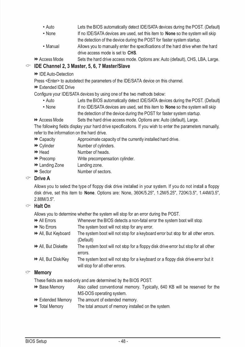
7/29/2019 GA-P55-UD3 Manual
http://slidepdf.com/reader/full/ga-p55-ud3-manual 48/128
BIOS Setup - 48 -
• Auto Lets the BIOS automatically detect IDE/SATA devices during the POST. (Default)
•None If no IDE/SATA devices are used, set this item to None so the system will skip
the detection of the device during the POST for faster system startup.
•Manual Allowsyoutomanuallyenterthespecicationsoftheharddrivewhenthehard
drive access mode is set to CHS.
Access Mode Sets the hard drive access mode. Options are: Auto (default), CHS, LBA, Large.IDE Channel 2, 3 Master, 5, 6, 7 Master/Slave
IDE Auto-Detection
Press <Enter> to autodetect the parameters of the IDE/SATA device on this channel.
Extended IDE Drive
CongureyourIDE/SATAdevicesbyusingoneofthetwomethodsbelow:
• Auto Lets the BIOS automatically detect IDE/SATA devices during the POST. (Default)
•None If no IDE/SATA devices are used, set this item to None so the system will skip
the detection of the device during the POST for faster system startup.
Access Mode Sets the hard drive access mode. Options are: Auto (default), Large. Thefollowingeldsdisplayyourharddrivespecications.Ifyouwishtoentertheparametersmanually,
refer to the information on the hard drive.
Capacity Approximate capacity of the currently installed hard drive.
Cylinder Number of cylinders.
Head Number of heads.
Precomp Write precompensation cylinder.
Landing Zone Landing zone.
Sector Number of sectors.
Drive A
Allowsyoutoselectthetypeofoppydiskdriveinstalledinyoursystem.Ifyoudonotinstallaoppy
disk drive, set this item to None. Options are: None, 360K/5.25", 1.2M/5.25", 720K/3.5", 1.44M/3.5",
2.88M/3.5".
Halt On
Allows you to determine whether the system will stop for an error during the POST.
All Errors Whenever the BIOS detects a non-fatal error the system boot will stop.
No Errors The system boot will not stop for any error.
All, But Keyboard The system boot will not stop for a keyboard error but stop for all other errors.
(Default)
All,ButDiskette Thesystembootwillnotstopforaoppydiskdriveerrorbutstopforallother
errors.
All,ButDisk/Key Thesystembootwillnotstopforakeyboardoraoppydiskdriveerrorbutit
will stop for all other errors.
Memory
Theseeldsareread-onlyandaredeterminedbytheBIOSPOST.
Base Memory Also called conventional memory. Typically, 640 KB will be reserved for the
MS-DOS operating system.
Extended Memory The amount of extended memory.
Total Memory The total amount of memory installed on the system.

7/29/2019 GA-P55-UD3 Manual
http://slidepdf.com/reader/full/ga-p55-ud3-manual 49/128
- 49 - BIOS Setup
(Note) This item is present only if you install a CPU that supports this feature. For more information about
Intel CPUs' unique features, please visit Intel's website.
2-5 Advanced BIOS Features
Hard Disk Boot Priority
Speciesthesequenceofloading theoperatingsystemfromtheinstalledharddrives.Usetheupor
down arrow key to select a hard drive, then press the plus key <+> (or <PageUp>) or the minus key <-> (or
<PageDown>)tomoveitupordownonthelist.Press<Esc>toexitthismenuwhennished.
Quick Boot
Enables or disables the quick boot function to speed up the system boot-up process to shorten the wait-
ingtimeforenteringtheoperatingsystemandtodelivergreaterefciencyfordailyuse.Thesettings
here synchronize with the settings of the SMART QuickBoot of Smart 6™. (Default: Disabled)
First/Second/Third Boot Device
Speciesthebootorderfromtheavailabledevices.Usetheupordownarrowkeytoselectadevice
and press <Enter> to accept. Options are: Floppy, LS120, Hard Disk, CDROM, ZIP, USB-FDD, USB-ZIP,
USB-CDROM, USB-HDD, Legacy LAN, Disabled.
Password Check
Specieswhetherapasswordis requiredeverytime thesystemboots,oronlywhenyouenterBIOSSetup.Afterconguringthisitem,setthepassword(s)undertheSet Supervisor/User Password item in
the BIOS Main Menu.
Setup A password is only required for entering the BIOS Setup program. (Default)
System A password is required for booting the system and for entering the BIOS Setup
program.
HDD S.M.A.R.T. Capability
Enables or disables the S.M.A.R.T. (Self Monitoring and Reporting Technology) capability of your hard
drive. This feature allows your system to report read/write errors of the hard drive and to issue warnings
when a third party hardware monitor utility is installed. (Default: Disabled)
CMOS Setup Utility-Copyright (C) 1984-2009 Award Software
Advanced BIOS Features
Hard Disk Boot Priority [Press Enter]
Quick Boot [Disabled]
First Boot Device [Hard Disk]
Second Boot Device [CDROM]Third Boot Device [Floppy]
Password Check [Setup]
HDD S.M.A.R.T. Capability [Disabled]
Limit CPUID Max. to 3 (Note) [Disabled]
No-Execute Memory Protect (Note) [Enabled]
Delay For HDD (Secs) [0]
Full Screen LOGO Show [Enabled]
Backup BIOS Image to HDD [Disabled]
Init Display First [PCI]
higf: Move Enter: Select +/-/PU/PD: Value F10: Save ESC: Exit F1: General Help
F5: Previous Values F6: Fail-Safe Defaults F7: Optimized Defaults
Item Help
Menu Level
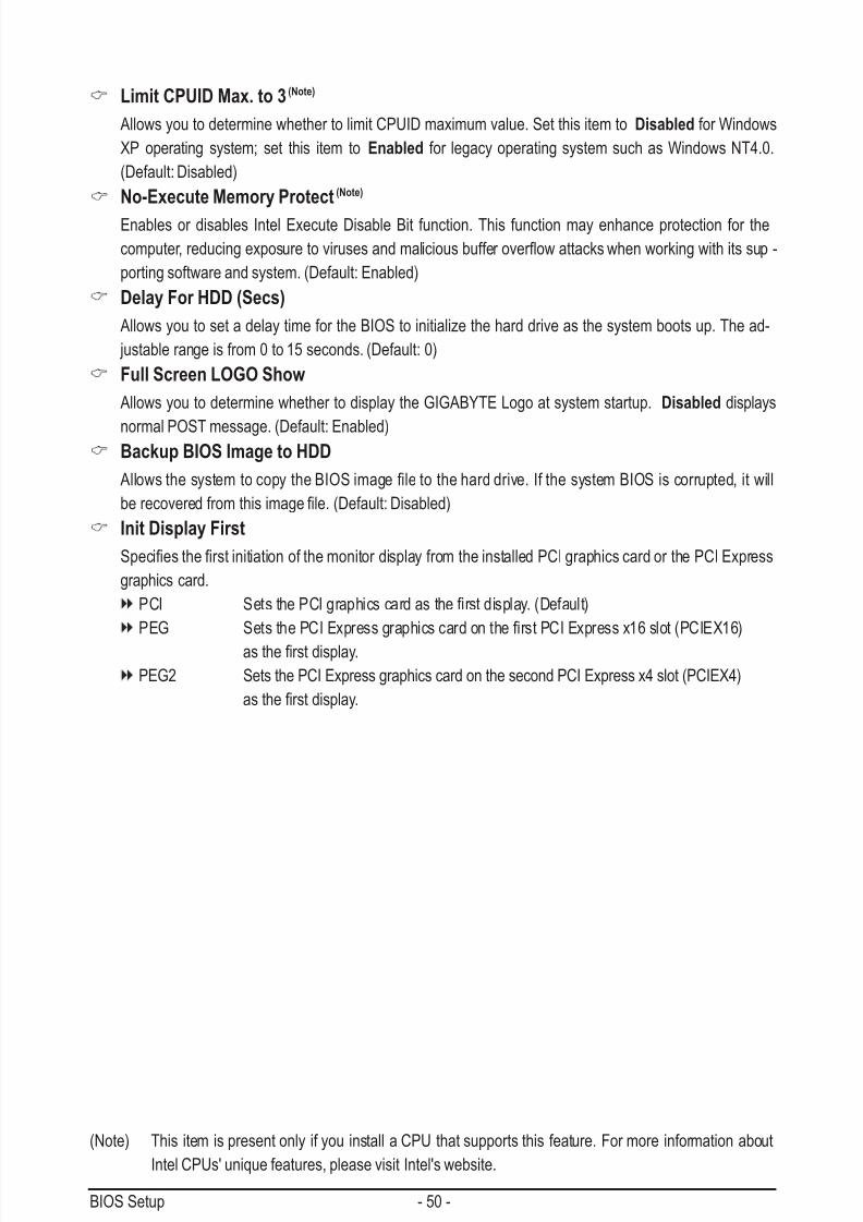
7/29/2019 GA-P55-UD3 Manual
http://slidepdf.com/reader/full/ga-p55-ud3-manual 50/128
BIOS Setup - 50 -
Limit CPUID Max. to 3 (Note)
Allows you to determine whether to limit CPUID maximum value. Set this item to Disabled for Windows
XP operating system; set this item to Enabled for legacy operating system such as Windows NT4.0.
(Default: Disabled)
No-Execute Memory Protect (Note)
Enables or disables Intel Execute Disable Bit function. This function may enhance protection for the
computer,reducingexposuretovirusesandmaliciousbufferoverowattackswhenworkingwithitssup-
porting software and system. (Default: Enabled)
Delay For HDD (Secs)
Allows you to set a delay time for the BIOS to initialize the hard drive as the system boots up. The ad-
justable range is from 0 to 15 seconds. (Default: 0)
Full Screen LOGO Show
Allows you to determine whether to display the GIGABYTE Logo at system startup. Disabled displays
normal POST message. (Default: Enabled)Backup BIOS Image to HDD
AllowsthesystemtocopytheBIOSimageletotheharddrive.IfthesystemBIOSiscorrupted,itwill
berecoveredfromthisimagele.(Default:Disabled)
Init Display First
SpeciestherstinitiationofthemonitordisplayfromtheinstalledPCIgraphicscardorthePCIExpress
graphics card.
PCI SetsthePCIgraphicscardastherstdisplay.(Default)
PEG SetsthePCIExpressgraphicscardontherstPCIExpressx16slot(PCIEX16)
astherstdisplay.
PEG2 Sets the PCI Express graphics card on the second PCI Express x4 slot (PCIEX4)
astherstdisplay.
(Note) This item is present only if you install a CPU that supports this feature. For more information about
Intel CPUs' unique features, please visit Intel's website.

7/29/2019 GA-P55-UD3 Manual
http://slidepdf.com/reader/full/ga-p55-ud3-manual 51/128
- 51 - BIOS Setup
2-6 Integrated Peripherals
SATA RAID/AHCI Mode (Intel P55 Chipset)
EnablesordisablesRAIDfortheSATAcontrollersintegratedintheIntelP55chipsetorconguresthe
SATA controllers to AHCI mode.
Disabled DisablesRAIDfortheSATAcontrollersandcongurestheSATAcontrollerstoIDE
mode. (Default)
RAID Enables RAID for the SATA controllers. AHCI CongurestheSATAcontrollerstoAHCImode.AdvancedHostControllerInterface
(AHCI)isaninterfacespecicationthatallowsthestoragedrivertoenableadvanced
Serial ATA features such as Native Command Queuing and hot plug.
SATA Port0-3 Native Mode (Intel P55 Chipset)
SpeciestheoperatingmodeoftheintegratedSATAcontrollers.
Disabled Allows the SATA controllers to operate in Legacy IDE mode.
In Legacy mode the SATA controllers use dedicated IRQs that cannot be shared with
other device. Set this option to Disabled if you wish to install operating systems that
do not support Native mode. (Default)
Enabled Allows the SATA controllers to operate in Native IDE mode.
Enable Native IDE mode if you wish to install operating systems that support Native
mode.
USB Controllers
Enables or disables the integrated USB 1.0 controller. (Default: Enabled)
Disabled will turn off all of the USB functionalities below.
USB Legacy Function
Allows USB keyboard to be used in MS-DOS. (Default: Enabled)USB Storage Function
DetermineswhethertodetectUSBstoragedevices, includingUSBashdrivesandUSBharddrives
during the POST. (Default: Enabled)
CMOS Setup Utility-Copyright (C) 1984-2009 Award Software
Integrated Peripherals
SATA RAID/AHCI Mode [Disabled]
SATA Port0-3 Native Mode [Enabled]
USB Controllers [Enabled]
USB Legacy Function [Enabled]USB Storage Function [Enabled]
Azalia Codec [Auto]
Onboard H/W LAN [Enabled]
Green LAN [Disabled]
SMART LAN [Press Enter]
Onboard LAN Boot ROM [Disabled]
eSATA Controller [Enabled]
eSATA Ctrl Mode [IDE]
GSATA 0_1/IDE Controller [Enabled]
GSATA 0_1/IDE Ctrl Mode [IDE]
Onboard Serial Port 1 [3F8/IRQ4]
Onboard Parallel Port [378/IRQ7]
Parallel Port Mode [SPP]
higf: Move Enter: Select +/-/PU/PD: Value F10: Save ESC: Exit F1: General Help
F5: Previous Values F6: Fail-Safe Defaults F7: Optimized Defaults
Item Help
Menu Level
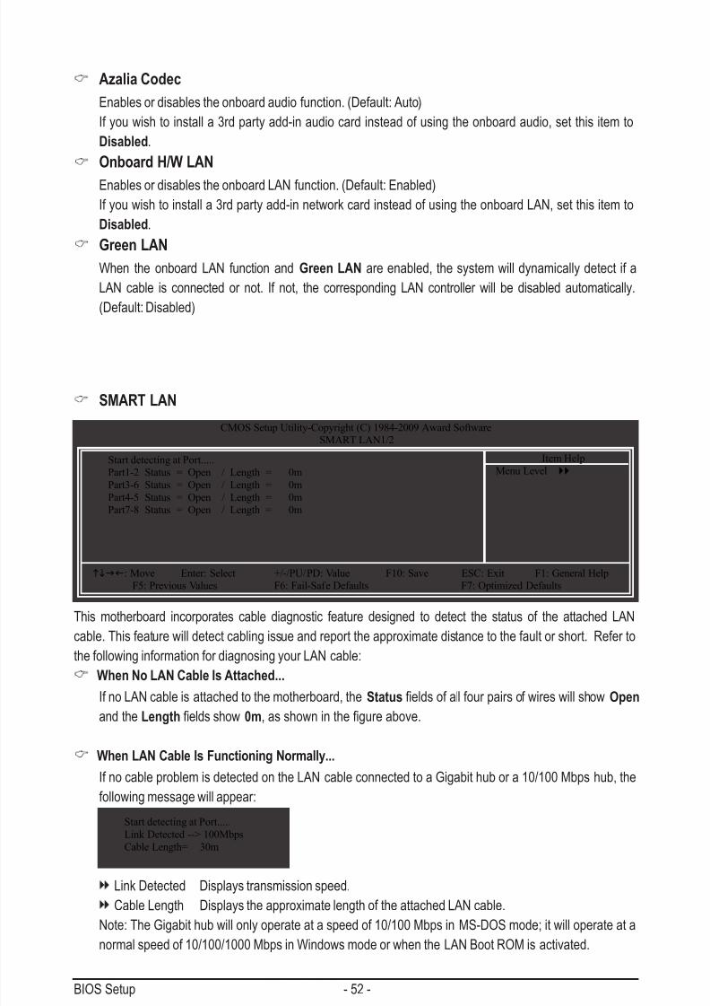
7/29/2019 GA-P55-UD3 Manual
http://slidepdf.com/reader/full/ga-p55-ud3-manual 52/128
BIOS Setup - 52 -
Azalia Codec
Enables or disables the onboard audio function. (Default: Auto)
If you wish to install a 3rd party add-in audio card instead of using the onboard audio, set this item to
Disabled.
Onboard H/W LAN
Enables or disables the onboard LAN function. (Default: Enabled)
If you wish to install a 3rd party add-in network card instead of using the onboard LAN, set this item to
Disabled.
Green LAN
When the onboard LAN function and Green LAN are enabled, the system will dynamically detect if a
LAN cable is connected or not. If not, the corresponding LAN controller will be disabled automatically.
(Default: Disabled)
CMOS Setup Utility-Copyright (C) 1984-2009 Award Software
SMART LAN1/2
Start detecting at Port.....
Part1-2 Status = Open / Length = 0m
Part3-6 Status = Open / Length = 0m
Part4-5 Status = Open / Length = 0m
Part7-8 Status = Open / Length = 0m
higf: Move Enter: Select +/-/PU/PD: Value F10: Save ESC: Exit F1: General Help
F5: Previous Values F6: Fail-Safe Defaults F7: Optimized Defaults
Item Help
Menu Level
This motherboard incorporates cable diagnostic feature designed to detect the status of the attached LAN
cable. This feature will detect cabling issue and report the approximate distance to the fault or short. Refer to
the following information for diagnosing your LAN cable:
When No LAN Cable Is Attached...
If no LAN cable is attached to the motherboard, the StatuseldsofallfourpairsofwireswillshowOpen
and the Lengtheldsshow0m,asshowninthegureabove.
When LAN Cable Is Functioning Normally...
If no cable problem is detected on the LAN cable connected to a Gigabit hub or a 10/100 Mbps hub, the
following message will appear:
Start detecting at Port.....
Link Detected --> 100Mbps
Cable Length= 30m
SMART LAN
Link Detected Displays transmission speed.Cable Length Displays the approximate length of the attached LAN cable.
Note: The Gigabit hub will only operate at a speed of 10/100 Mbps in MS-DOS mode; it will operate at a
normal speed of 10/100/1000 Mbps in Windows mode or when the LAN Boot ROM is activated.
7/29/2019 GA-P55-UD3 Manual
http://slidepdf.com/reader/full/ga-p55-ud3-manual 53/128
- 53 - BIOS Setup
Onboard LAN Boot ROM
Allows you to decide whether to activate the boot ROM integrated with the onboard LAN chip.
(Default: Disabled)
eSATA Controller (JMB362 Chip, eSATA Connectors)
Enables or disables the SATA controller integrated in the JMB362 chip. (Default: Enabled)
eSATA Ctrl Mode (JMB362 Chip, eSATA Connectors) EnablesordisablesRAIDfortheSATAcontrollerintegratedintheJMB362chiporcongurestheSATA
controller to AHCI mode.
IDE DisablesRAIDfortheSATAcontrollerandcongurestheSATAcontrollertoIDE
mode. (Default)
AHCI CongurestheSATAcontrollertoAHCImode.AdvancedHostControllerInterface
(AHCI)isaninterfacespecicationthatallowsthestoragedrivertoenableadvanced
Serial ATA features such as Native Command Queuing and hot plug.
RAID Enables RAID for the SATA controller.
GSATA 0_1/IDE Controller (GIGABYTE SATA2, IDE and GSATA2_0/1 Connectors)Enables or disables the IDE and SATA controllers integrated in the GIGABYTE SATA2 chip.
(Default: Enabled)
GSATA 0_1/IDE Ctrl Mode (GIGABYTE SATA2, IDE and GSATA2_0/1 Connectors)
EnablesordisablesRAIDfortheSATAcontrollerintegratedintheGIGABYTESATA2chiporcongures
the SATA controller to AHCI mode.
IDE DisablesRAIDfortheSATAcontrollerandcongurestheSATAcontrollertoIDE
mode. (Default)
AHCI CongurestheSATAcontrollertoAHCImode.AdvancedHostControllerInterface
(AHCI)isaninterfacespecicationthatallowsthestoragedrivertoenableadvanced
Serial ATA features such as Native Command Queuing and hot plug.
RAID/IDE Enables RAID for the SATA controller; the IDE controller still operates in IDE mode.
Onboard Serial Port 1
EnablesordisablestherstserialportandspeciesitsbaseI/Oaddressandcorrespondinginterrupt.
Options are: Auto, 3F8/IRQ4 (default), 2F8/IRQ3, 3E8/IRQ4, 2E8/IRQ3, Disabled.
Onboard Parallel Port
Enablesordisablestheonboardparallelport(LPT)andspeciesitsbaseI/Oaddressandcorrespond-
ing interrupt. Options are: 378/IRQ7 (default), 278/IRQ5, 3BC/IRQ7, Disabled.Parallel Port Mode
Selects an operating mode for the onboard parallel (LPT) port. Options are: SPP (Standard Parallel Port)
(default), EPP (Enhanced Parallel Port), ECP (Extended Capabilities Port), ECP+EPP.
When a Cable Problem Occurs...
Ifacableproblemoccursonaspeciedpairofwires,theStatuseldwillshowShort and then length
shown will be the approximate distance to the fault or short.
Example: Part1-2 Status = Short / Length = 2m
Explanation: A fault or short might occur at about 2m on Part 1-2.
Note: Part 4-5 and Part 7-8 are not used in a 10/100 Mbps environment, so their StatuseldswillshowOpen, and the length shown is the approximate length of the attached LAN cable.

7/29/2019 GA-P55-UD3 Manual
http://slidepdf.com/reader/full/ga-p55-ud3-manual 54/128
BIOS Setup - 54 -
ACPI Suspend Type
SpeciestheACPIsleepstatewhenthesystementerssuspend.
S1(POS) Enables the system to enter the ACPI S1 (Power on Suspend) sleep state.
In S1 sleep state, the system appears suspended and stays in a low power mode.
The system can be resumed at any time.
S3(STR) Enables the system to enter the ACPI S3 (Suspend to RAM) sleep state (default).In S3 sleep state, the system appears to be off and consumes less power than in
the S1 state. When signaled by a wake-up device or event, the system resumes to
its working state exactly where it was left off.
Soft-Off by PWR-BTTN
ConguresthewaytoturnoffthecomputerinMS-DOSmodeusingthepowerbutton.
Instant-Off Press the power button and then the system will be turned off instantly. (Default)
Delay 4 Sec. Press and hold the power button for 4 seconds to turn off the system. If the power
button is pressed for less than 4 seconds, the system will enter suspend mode.
PME Event Wake Up
Allows the system to be awakened from an ACPI sleep state by a wake-up signal from a PCI or PCIe de-
vice. Note: To use this function, you need an ATX power supply providing at least 1A on the +5VSB lead.
(Default: Enabled)
Power On by Ring
Allows the system to be awakened from an ACPI sleep state by a wake-up signal from a modem that
supports wake-up function. (Default: Enabled)
(Note) Supported on Windows Vista operating system only.
2-7 Power Management SetupCMOS Setup Utility-Copyright (C) 1984-2009 Award Software
Power Management Setup
ACPI Suspend Type [S3(STR)]
Soft-Off by PWR-BTTN [Instant-Off]
PME Event Wake Up [Enabled]
Power On by Ring [Enabled]Resume by Alarm [Disabled]
x Date (of Month) Alarm Everyday
x Time (hh:mm:ss) Alarm 0 : 0 : 0
HPET Support (Note) [Enabled]
HPET Mode (Note) [32-bit mode]
Power On By Mouse [Disabled]
Power On By Keyboard [Disabled]
x KB Power ON Password Enter
AC Back Function [Soft-Off]
higf: Move Enter: Select +/-/PU/PD: Value F10: Save ESC: Exit F1: General Help
F5: Previous Values F6: Fail-Safe Defaults F7: Optimized Defaults
Item Help
Menu Level

7/29/2019 GA-P55-UD3 Manual
http://slidepdf.com/reader/full/ga-p55-ud3-manual 55/128
- 55 - BIOS Setup
(Note) Supported on Windows Vista operating system only.
Resume by Alarm
Determines whether to power on the system at a desired time. (Default: Disabled)
If enabled, set the date and time as following:
Date(ofMonth)Alarm:Turnonthesystemataspecictimeoneachdayoronaspecicdayina
month.
Time (hh: mm: ss) Alarm: Set the time at which the system will be powered on automatically.
Note: When using this function, avoid inadequate shutdown from the operating system or removal of the
AC power, or the settings may not be effective.
HPET Support (Note)
Enables or disables High Precision Event Timer (HPET) for Windows Vista operating system.
(Default: Enabled)
HPET Mode (Note)
Allows you to select the HPET mode for your Windows Vista operating system. Select 32-bit mode
when you install 32-bit Windows Vista; select 64-bit mode when you install 64-bit Windows Vista. ThisitemiscongurableonlyiftheHPET Support is set to Enabled. (Default: 32-bit mode)
Power On By Mouse
Allows the system to be turned on by a PS/2 mouse wake-up event.
Note: To use this function, you need an ATX power supply providing at least 1A on the +5VSB lead.
Disabled Disables this function. (Default)
Double Click Double click on left button on the PS/2 mouse to turn on the system.
Power On By Keyboard
Allows the system to be turned on by a PS/2 keyboard wake-up event.
Note: you need an ATX power supply providing at least 1A on the +5VSB lead.Disabled Disables this function. (Default)
Password Set a password with 1~5 characters to turn on the system.
Keyboard 98 Press POWER button on the Windows 98 keyboard to turn on the system.
KB Power ON Password
Set the password when Power On by Keyboard is set to Password. Press <Enter> on this item and set
a password with up to 5 characters and then press <Enter> to accept. To turn on the system, enter the
password and press <Enter>.
Note: To cancel the password, press <Enter> on this item. When prompted for the password, press
<Enter> again without entering the password to clear the password settings.
AC Back Function
Determines the state of the system after the return of power from an AC power loss.
Soft-Off The system stays off upon the return of the AC power. (Default)
Full-On The system is turned on upon the return of the AC power.
Memory The system returns to its last known awake state upon the return of the AC power.
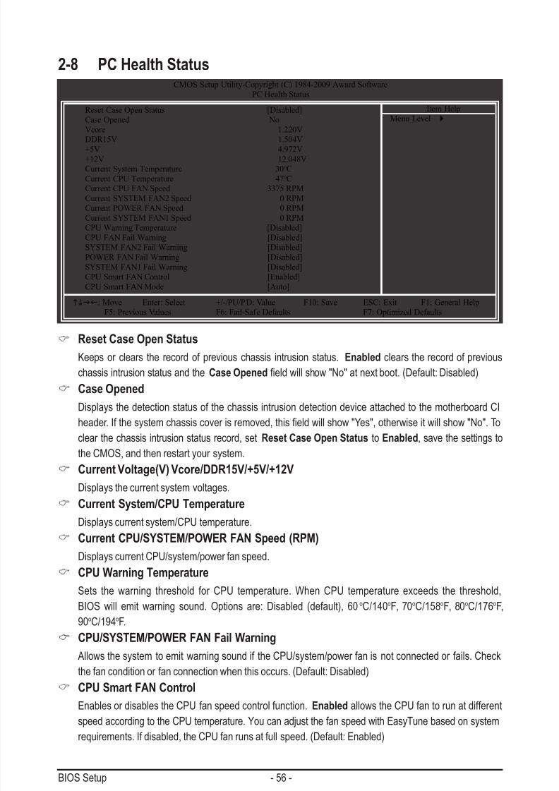
7/29/2019 GA-P55-UD3 Manual
http://slidepdf.com/reader/full/ga-p55-ud3-manual 56/128
BIOS Setup - 56 -
Reset Case Open Status
Keeps or clears the record of previous chassis intrusion status. Enabled clears the record of previous
chassis intrusion status and the Case Openedeldwillshow"No"atnextboot.(Default:Disabled)
Case Opened
Displays the detection status of the chassis intrusion detection device attached to the motherboard CI
header.Ifthesystemchassiscoverisremoved,thiseldwillshow"Yes",otherwiseitwillshow"No".To
clear the chassis intrusion status record, set Reset Case Open Status to Enabled, save the settings to
the CMOS, and then restart your system.
Current Voltage(V) Vcore/DDR15V/+5V/+12V
Displays the current system voltages.
Current System/CPU Temperature
Displays current system/CPU temperature.
Current CPU/SYSTEM/POWER FAN Speed (RPM)
Displays current CPU/system/power fan speed.CPU Warning Temperature
Sets the warning threshold for CPU temperature. When CPU temperature exceeds the threshold,
BIOS will emit warning sound. Options are: Disabled (default), 60oC/140oF, 70oC/158oF, 80oC/176oF,
90oC/194oF.
CPU/SYSTEM/POWER FAN Fail Warning
Allows the system to emit warning sound if the CPU/system/power fan is not connected or fails. Check
the fan condition or fan connection when this occurs. (Default: Disabled)
CPU Smart FAN Control
Enables or disables the CPU fan speed control function. Enabled allows the CPU fan to run at different
speed according to the CPU temperature. You can adjust the fan speed with EasyTune based on system
requirements. If disabled, the CPU fan runs at full speed. (Default: Enabled)
2-8 PC Health StatusCMOS Setup Utility-Copyright (C) 1984-2009 Award Software
PC Health Status
Reset Case Open Status [Disabled]
Case Opened No
Vcore 1.220V
DDR15V 1.504V+5V 4.972V
+12V 12.048V
Current System Temperature 30oC
Current CPU Temperature 47oC
Current CPU FAN Speed 3375 RPM
Current SYSTEM FAN2 Speed 0 RPM
Current POWER FAN Speed 0 RPM
Current SYSTEM FAN1 Speed 0 RPM
CPU Warning Temperature [Disabled]
CPU FAN Fail Warning [Disabled]
SYSTEM FAN2 Fail Warning [Disabled]
POWER FAN Fail Warning [Disabled]
SYSTEM FAN1 Fail Warning [Disabled]
CPU Smart FAN Control [Enabled]CPU Smart FAN Mode [Auto]
higf: Move Enter: Select +/-/PU/PD: Value F10: Save ESC: Exit F1: General Help
F5: Previous Values F6: Fail-Safe Defaults F7: Optimized Defaults
Item Help
Menu Level
7/29/2019 GA-P55-UD3 Manual
http://slidepdf.com/reader/full/ga-p55-ud3-manual 57/128
- 57 - BIOS Setup
CPU Smart FAN Control
SpecieshowtocontrolCPUfanspeed.ThisitemiscongurableonlyifCPU Smart FAN Control is set
to Enabled.
Auto Lets the BIOS automatically detect the type of CPU fan installed and sets the optimal
CPU fan control mode. (Default)
Voltage Sets Voltage mode for a 3-pin CPU fan.
PWM Sets PWM mode for a 4-pin CPU fan.
Note: The Voltage mode can be set for a 3-pin CPU fan or a 4-pin CPU fan. However, for a 4-pin CPU
fanthatisnotdesignedfollowingIntelPWMfanspecications,selectingPWM mode may not effectively
reduce the fan speed.

7/29/2019 GA-P55-UD3 Manual
http://slidepdf.com/reader/full/ga-p55-ud3-manual 58/128
BIOS Setup - 58 -
Press <Enter> on this item and then press the <Y> key to load the safest BIOS default settings.
In case system instability occurs, you may try to load Fail-Safe defaults, which are the safest and most stable
BIOS settings for the motherboard.
2-9 Load Fail-Safe Defaults
Press <Enter> on this item and then press the <Y> key to load the optimal BIOS default settings.
The BIOS defaults settings help the system to operate in optimum state. Always load the Optimized defaults
after updating the BIOS or after clearing the CMOS values.
2-10 Load Optimized DefaultsCMOS Setup Utility-Copyright (C) 1984-2009 Award Software
Load Optimized Defaults
MB Intelligent Tweaker(M.I.T.)
Standard CMOS Features
Advanced BIOS Features
Integrated Peripherals
Power Management Setup
PC Health Status
Load Fail-Safe Defaults
ESC: Quit higf: Select Item F11: Save CMOS to BIOS
F8: Q-Flash F10: Save & Exit Setup F12: Load CMOS from BIOS
Load Optimized Defaults
Set Supervisor Password
Set User Password
Save & Exit Setup
Exit Without Saving
SecurityChipCongurationjLoad Optimized Defaults (Y/N)? N
CMOS Setup Utility-Copyright (C) 1984-2009 Award Software
Load Fail-Safe Defaults
ESC: Quit higf: Select Item F11: Save CMOS to BIOS
F8: Q-Flash F10: Save & Exit Setup F12: Load CMOS from BIOS
Load Optimized Defaults
Set Supervisor Password
Set User Password
Save & Exit Setup
Exit Without Saving
SecurityChipCongurationj
MB Intelligent Tweaker(M.I.T.)
Standard CMOS Features
Advanced BIOS Features
Integrated Peripherals
Power Management Setup
PC Health Status
Load Fail-Safe Defaults
Load Fail-Safe Defaults (Y/N)? N
j Only for GA-P55-UD3P.

7/29/2019 GA-P55-UD3 Manual
http://slidepdf.com/reader/full/ga-p55-ud3-manual 59/128
- 59 - BIOS Setup
Press <Enter> on this item and type the password with up to 8 characters and then press <Enter>. You will
berequestedtoconrmthepassword.Typethepasswordagainandpress<Enter>.
The BIOS Setup program allows you to specify two separate passwords:
Supervisor Password
When a system password is set and the Password Check item in Advanced BIOS Features is set to
Setup, you must enter the supervisor password for entering BIOS Setup and making BIOS changes.
When the Password Check item is set to System, you must enter the supervisor password (or user
password) at system startup and when entering BIOS Setup.
User Password
When the Password Check item is set to System, you must enter the supervisor password (or user password) at system startup to continue system boot. In BIOS Setup, you must enter the supervisor
password if you wish to make changes to BIOS settings. The user password only allows you to view the
BIOS settings but not to make changes.
To clear the password, press <Enter> on the password item and when requested for the password, press
<Enter> again. The message "PASSWORD DISABLED" will appear, indicating the password has been can-
celled.
2-11 Set Supervisor/User Password
CMOS Setup Utility-Copyright (C) 1984-2009 Award Software
Change/Set/Disable Password
MB Intelligent Tweaker(M.I.T.)
Standard CMOS Features
Advanced BIOS Features
Integrated Peripherals
Power Management Setup
PC Health Status
Load Fail-Safe Defaults
ESC: Quit higf: Select Item F11: Save CMOS to BIOS
F8: Q-Flash F10: Save & Exit Setup F12: Load CMOS from BIOS
Load Optimized Defaults
Set Supervisor Password
Set User Password
Save & Exit Setup
Exit Without Saving
SecurityChipCongurationjEnter Password:
j Only for GA-P55-UD3P.

7/29/2019 GA-P55-UD3 Manual
http://slidepdf.com/reader/full/ga-p55-ud3-manual 60/128
BIOS Setup - 60 -
Press <Enter> on this item and press the <Y> key. This saves the changes to the CMOS and exits the BIOS
Setup program. Press <N> or <Esc> to return to the BIOS Setup Main Menu.
2-12 Save & Exit Setup
Press <Enter> on this item and press the <Y> key. This exits the BIOS Setup without saving the changes
made in BIOS Setup to the CMOS. Press <N> or <Esc> to return to the BIOS Setup Main Menu.
2-13 Exit Without Saving
CMOS Setup Utility-Copyright (C) 1984-2009 Award Software
Save Data to CMOS
MB Intelligent Tweaker(M.I.T.)
Standard CMOS Features
Advanced BIOS Features
Integrated Peripherals
Power Management Setup
PC Health Status
Load Fail-Safe Defaults
ESC: Quit higf: Select Item F11: Save CMOS to BIOS
F8: Q-Flash F10: Save & Exit Setup F12: Load CMOS from BIOS
Load Optimized Defaults
Set Supervisor Password
Set User Password
Save & Exit Setup
Exit Without Saving
SecurityChipCongurationjSave to CMOS and EXIT (Y/N)? Y
CMOS Setup Utility-Copyright (C) 1984-2009 Award Software
Abandon all Data
MB Intelligent Tweaker(M.I.T.)
Standard CMOS Features
Advanced BIOS Features
Integrated Peripherals
Power Management Setup
PC Health Status
Load Fail-Safe Defaults
ESC: Quit higf: Select Item F11: Save CMOS to BIOS
F8: Q-Flash F10: Save & Exit Setup F12: Load CMOS from BIOS
Load Optimized Defaults
Set Supervisor Password
Set User Password
Save & Exit Setup
Exit Without Saving
SecurityChipCongurationj
Quit Without Saving (Y/N)? N
j Only for GA-P55-UD3P.

7/29/2019 GA-P55-UD3 Manual
http://slidepdf.com/reader/full/ga-p55-ud3-manual 61/128
- 61 - BIOS Setup
Security Chip
Enables or disables the security chip. It is recommended that you use this function with the Supervisor/
User password.
Enabled/Activate Enables the security chip and initializes the Security Platform.
Disabled Disables the security chip. (Default)
Security Chip StateDisplays the current settings in the security chip.
2-14 Security Chip Conguration jCMOS Setup Utility-Copyright (C) 1984-2009 Award Software
SecurityChipConguration
Security Chip [Disabled]
Security Chip State Disabled/Deactivated
higf: Move Enter: Select +/-/PU/PD: Value F10: Save ESC: Exit F1: General Help
F5: Previous Values F6: Fail-Safe Defaults F7: Optimized Defaults
Item Help
Menu Level
j Only for GA-P55-UD3P.

7/29/2019 GA-P55-UD3 Manual
http://slidepdf.com/reader/full/ga-p55-ud3-manual 62/128
BIOS Setup - 62 -

7/29/2019 GA-P55-UD3 Manual
http://slidepdf.com/reader/full/ga-p55-ud3-manual 63/128
- 63 - Drivers Installation
3-1 Installing Chipset Drivers
Chapter 3 Drivers Installation
• Beforeinstallingthedrivers,rstinstalltheoperatingsystem.
• After installing the operating system, insert the motherboard driver disk into your optical drive.
The driver Autorun screen is automatically displayed which looks like that shown in the screen
shot below. (If the driver Autorun screen does not appear automatically, go to My Computer,
double-click the optical drive and execute the Run.exe program.)
After inserting the driver disk, "Xpress Install" will automatically scan your system and then list all the drivers
that are recommended to install. You can click the Install All button and "Xpress Install" will install all the rec-ommended drivers. Or click Install Single Items to manually select the drivers you wish to install.
• Please ignore the popup dialog box(es) (e.g. the Found New Hardware Wizard) displayed
when "Xpress Install" is installing the drivers. Failure to do so may affect the driver installation.
• Some device drivers will restart your system automatically during the driver installation. After the
system restart, "Xpress Install" will continue to install other drivers.
• After the drivers are installed, follow the on-screen instructions to restart your system. You can
install other applications included in the motherboard driver disk.
• For USB 2.0 driver support under the Windows XP operating system, please install the Windows
XP Service Pack 1 or later. After installing the SP1 (or later), if a question mark still exists in
Universal Serial Bus Controller in Device Manager , please remove the question mark (by
right-clicking your mouse and select Uninstall) and restart the system. (The system will then
autodetect and install the USB 2.0 driver.)
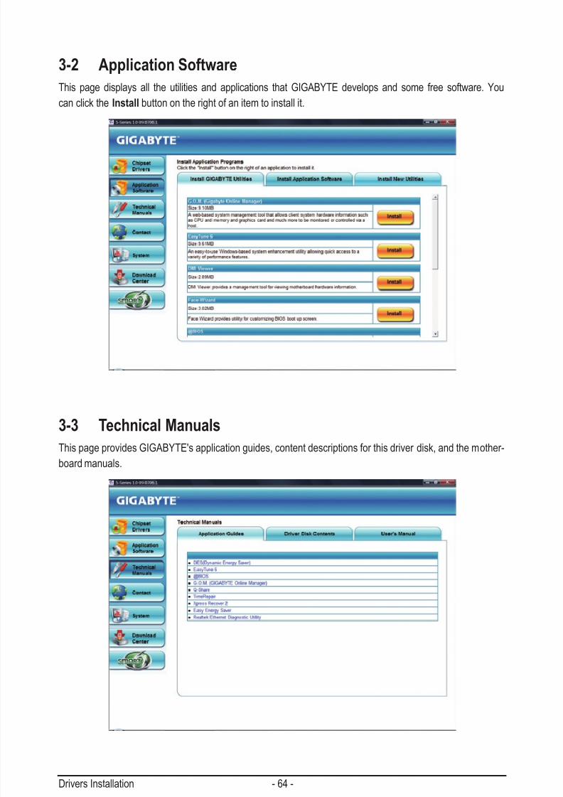
7/29/2019 GA-P55-UD3 Manual
http://slidepdf.com/reader/full/ga-p55-ud3-manual 64/128
Drivers Installation - 64 -
3-2 Application Software
This page displays all the utilities and applications that GIGABYTE develops and some free software. You
can click the Install button on the right of an item to install it.
3-3 Technical ManualsThis page provides GIGABYTE's application guides, content descriptions for this driver disk, and the mother-
board manuals.

7/29/2019 GA-P55-UD3 Manual
http://slidepdf.com/reader/full/ga-p55-ud3-manual 65/128
- 65 - Drivers Installation
3-4 Contact
ForthedetailedcontactinformationoftheGIGABYTETaiwanheadquarterorworldwidebranchofces,click
the URL on this page to link to the GIGABYTE website.
3-5 SystemThis page provides the basic system information.

7/29/2019 GA-P55-UD3 Manual
http://slidepdf.com/reader/full/ga-p55-ud3-manual 66/128
Drivers Installation - 66 -
3-6 Download Center
To update the BIOS, drivers, or applications, click the Download Center button to link to the GIGABYTE
website. The latest version of the BIOS, drivers, or applications will be displayed.
3-7 New UtilitiesThis page provides a quick link to GIGABYTE's lately developed utilities for users to install. You can click the
Install button on the right of an item to install it.

7/29/2019 GA-P55-UD3 Manual
http://slidepdf.com/reader/full/ga-p55-ud3-manual 67/128
- 67 - Unique Features
4-1 Xpress Recovery2
Chapter 4 Unique Features
Xpress Recovery2 is a utility that allows you to quickly compress and
back up your system data and perform restoration of it. Supporting NTFS,FAT32,andFAT16lesystems,XpressRecovery2canbackupdataon
PATA and SATA hard drives and restore it.
Before You Begin:
•XpressRecovery2willchecktherstphysicalharddrive (Note) for the operating system. Xpress Recovery2
canonlybackup/restoretherstphysicalharddrivethathastheoperatingsysteminstalled.
• AsXpressRecovery2willsavethebackupleattheendoftheharddrive,makesuretoleaveenoughun-
allocated space in advanced (10 GB or more is recommended; actual size requirements vary, depending
on the amount of data).
• It is recommended to back up your system soon after the operating system and drivers are installed.
•The amount of data and hard drive access speed may affect the speed at which the data is backed up/
restored.
• It takes longer to back up a hard drive than to restore it.
System Requirements:
• At least 512 MB of system memory
•VESA compatible graphics card
•Windows XP with SP1 or later, Windows Vista
• XpressRecoveryandXpressRecovery2aredifferentutilities.Forexample,abackuplecreatedwith Xpress Recovery cannot be restored using Xpress Recovery2.
• USB hard drives are not supported.
• Hard drives in RAID/AHCI mode are not supported.
Installation and Conguration:
Turn on your system to boot from the Windows Vista setup disk.
A. Installing Windows Vista and Partitioning the Hard Drive
(Note) XpressRecovery2checkstherstphysicalharddriveinthefollowingsequence:TherstPATAIDEconnector,the
secondPATAIDEconnector,therstSATAconnector,thesecondSATAconnectorandsoforth.Forexample,when
harddrivesareattachedtotherstIDEandtherstSATAconnectors,theharddriveontherstIDEconnectoris
therstphysicaldrive.WhenharddrivesareattachedtotherstandsecondSATAconnectors,theharddriveon
therstSATAconnectoristherstphysicaldrive.
Step 1:
Click Drive options.
Step 2:
Click New.

7/29/2019 GA-P55-UD3 Manual
http://slidepdf.com/reader/full/ga-p55-ud3-manual 68/128
Unique Features - 68 -
Step 3:
When partitioning your hard drive, make sure to
leave unallocated space (10 GB or more is recom-
mended; actual size requirements vary, depending
on the amount of data) and begin the installation of
the operating system.
Step 1:
Select BACKUP to start backing up your hard drive
data.
Step 4:
After the operating system is installed, right-click
the Computer icon on your desktop and select
Manage. Go to Disk Management to check disk
allocation.
Step 2:
Whennished,gotoDisk Management to check
disk allocation.
Step 5:
XpressRecovery2will savethebackuple totheunallocated
space (black stripe along the top). Please note that if there is no
enough unallocated space, Xpress Recovery2 cannot save the
backuple.
B. Accessing Xpress Recovery2
1. BootfromthemotherboarddriverdisktoaccessXpressRecovery2forthersttime.Whenyouseethe
following message: Press any key to startup Xpress Recovery2, press any key
to enter Xpress Recovery2.
2. Afteryouusethebackupfunction inXpressRecovery2forthersttime,XpressRecovery2willstay
permanent in your hard drive. If you wish to enter Xpress Recovery2 later, simply press <F9> during the
POST.
C. Using the Backup Function in Xpress Recovery2
Xpress Recovery2 will automatically create a
newpartitiontostorethebackupimagele.
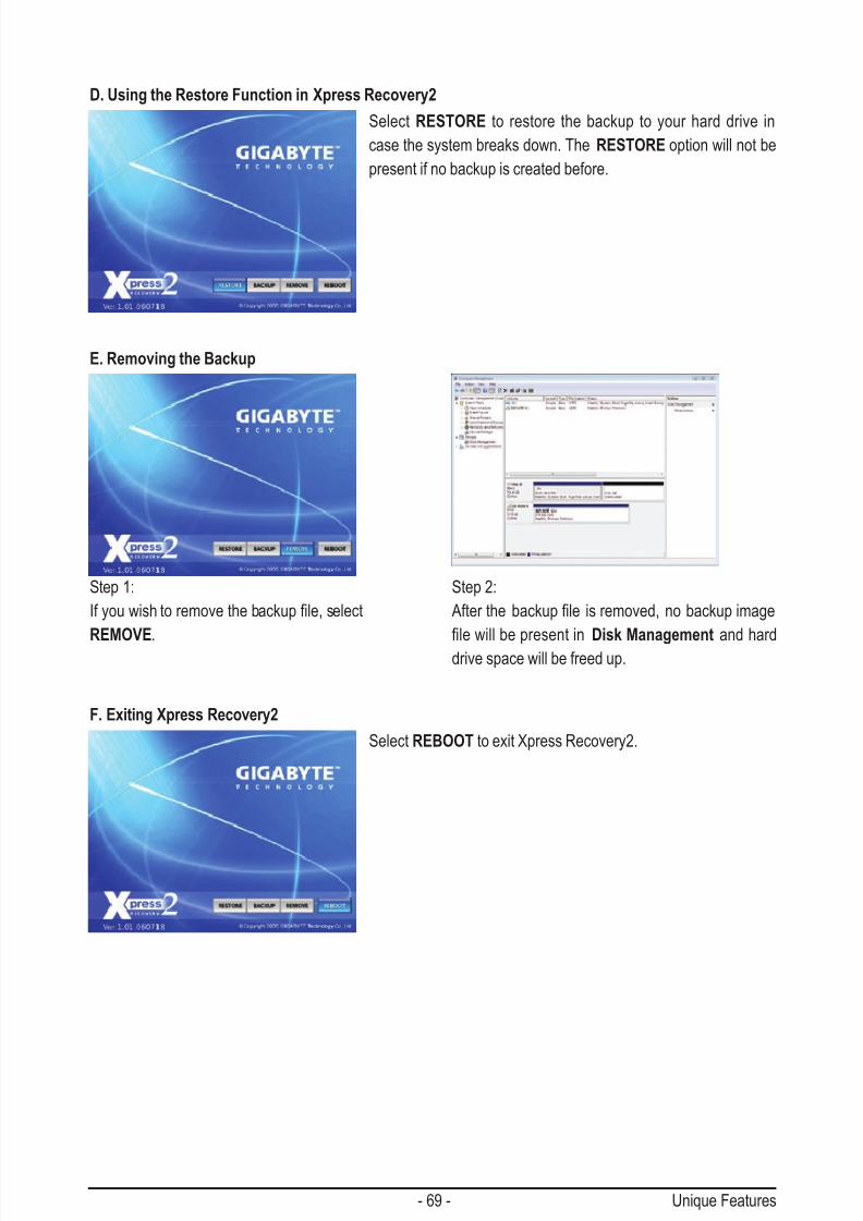
7/29/2019 GA-P55-UD3 Manual
http://slidepdf.com/reader/full/ga-p55-ud3-manual 69/128
- 69 - Unique Features
D. Using the Restore Function in Xpress Recovery2
E. Removing the Backup
F. Exiting Xpress Recovery2
Select RESTORE to restore the backup to your hard drive in
case the system breaks down. The RESTORE option will not be
present if no backup is created before.
Select REBOOT to exit Xpress Recovery2.
Step 2:
Afterthebackuple isremoved,nobackupimage
lewillbepresentinDisk Management and harddrive space will be freed up.
Step 1:
Ifyouwishtoremovethebackuple,select
REMOVE.

7/29/2019 GA-P55-UD3 Manual
http://slidepdf.com/reader/full/ga-p55-ud3-manual 70/128
Unique Features - 70 -
4-2 BIOS Update Utilities
GIGABYTE motherboards provide two unique BIOS update tools, Q-Flash™ and @BIOS™. GIGABYTE
Q-Flash and @BIOS are easy-to-use and allow you to update the BIOS without the need to enter MS-DOS
mode. Additionally, this motherboard features the DualBIOS
™
design, which enhances protection for thesafety and stability of your computer by adding one more physical BIOS chip.
What is DualBIOS™?
Motherboards that support DualBIOS have two BIOS onboard, a main BIOS and
a backup BIOS. Normally, the system works on the main BIOS. However, if the
main BIOS is corrupted or damaged, the backup BIOS will take over on the next system boot and copy the
BIOSletothemainBIOStoensurenormalsystemoperation.Forthesakeofsystemsafety,userscannot
update the backup BIOS manually.
What is Q-Flash
™
?With Q-Flash you can update the system BIOS without having to enter operating
systemslikeMS-DOSorWindowrst.EmbeddedintheBIOS,theQ-Flashtool
freesyoufromthehasslesofgoingthroughcomplicatedBIOSashingprocess.
What is @BIOS™?
@BIOS allows you to update the system BIOS while in the Windows environ-
ment.@BIOSwilldownloadthelatestBIOSlefromthenearest@BIOSserver
site and update the BIOS.
4-2-1 Updating the BIOS with the Q-Flash Utility
A. Before You Begin
1. FromGIGABYTE'swebsite,downloadthelatestcompressedBIOSupdatelethatmatchesyourmoth-
erboard model.
2. ExtracttheleandsavethenewBIOSle(e.g.p55ud3p.f1)toyouroppydisk,USBashdrive,orhard
drive.Note:TheUSBashdriveorharddrivemustuseFAT32/16/12lesystem.
3. Restart the system. During the POST, press the <End> key to enter Q-Flash. Note: You can access
Q-Flash by either pressing the <End> key during the POST or pressing the <F8> key in BIOS Setup.
However,iftheBIOSupdateleissavedtoaharddriveinRAID/AHCImodeoraharddriveattachedto
an independent IDE/SATA controller, use the <End> key during the POST to access Q-Flash.
BecauseBIOSashingispotentiallyrisky,pleasedoitwithcaution.InadequateBIOSashingmay
result in system malfunction.
Award Modular BIOS v6.00PG, An Energy Star AllyCopyright (C) 1984-2009, Award Software, Inc.
P55-UD3P D6....
<DEL>: BIOS Setup <F9>: XpressRecovery2 <F12>: Boot Menu <End>: Qflash
07/08/2009-P55-7A89RG0JC-00

7/29/2019 GA-P55-UD3 Manual
http://slidepdf.com/reader/full/ga-p55-ud3-manual 71/128
- 71 - Unique Features
B. Updating the BIOS
WhenupdatingtheBIOS,choosethelocationwheretheBIOSleissaved.Thefollowingprocedureas -
sumesthatyousavetheBIOSletoaoppydisk.
Step 1:
1. InserttheoppydiskcontainingtheBIOSleintotheoppydiskdrive.InthemainmenuofQ-Flash,use
the up or down arrow key to select Update BIOS from Drive and press <Enter>.
Step 2:
TheprocessofthesystemreadingtheBIOSlefromtheoppydiskisdisplayedonthescreen.Whenthe
message "Are you sure to update BIOS?" appears, press <Enter> to begin the BIOS update. The monitor will
display the update process.
Step 3:
When the update process is complete, press any key to return to the main menu.
2. Select Floppy A and press <Enter>.
3. SelecttheBIOSupdateleandpress<Enter>.
• The Save Main BIOS to DriveoptionallowsyoutosavethecurrentBIOSle.
• Q-FlashonlysupportsUSBashdriveorharddrivesusingFAT32/16/12lesystem.
• IftheBIOSupdateleissavedtoaharddriveinRAID/AHCImodeoraharddriveattachedto
an independent IDE/SATA controller, use the <End> key during the POST to access Q-Flash.
Q-Flash Utility v2.09
Flash Type/Size................................. MXIC 25L1605A 1M
Keep DMI Data Enable
Load CMOS Default Enable
Update BIOS from Drive
Save BIOS to Drive
Enter : Run hi:Move ESC:Reset F10:Power Off
Q-Flash Utility v2.09
Flash Type/Size................................. MXIC 25L1605A 1M
Keep DMI Data Enable
Load CMOS Default Enable
Update BIOS from Drive
Save BIOS to DriveEnter : Run hi:Move ESC:Reset F10:Power Off
!! Copy BIOS completed - Pass !!
Please press any key to continue
Make sure the BIOS update le matches your motherboard model.
• Do not turn off or restart the system when the system is reading/updating the BIOS.
• Do not remove the oppy disk, USB ash drive, or hard drive when the system is updat-
ing the BIOS.
Floppy A <Drive>
HDD 1-0 <Drive>
Total size : 0 Free size : 0
0le(s)found

7/29/2019 GA-P55-UD3 Manual
http://slidepdf.com/reader/full/ga-p55-ud3-manual 72/128
Unique Features - 72 -
Step 4:
Press <Esc> and then <Enter> to exit Q-Flash and reboot the system. As the system boots, you should see
the new BIOS version is present on the POST screen.
Step 5:
During the POST, press <Delete> to enter BIOS Setup. Select Load Optimized Defaults and press <Enter>to load BIOS defaults. System will re-detect all peripheral devices after a BIOS update, so we recommend
that you reload BIOS defaults.
Step 6:
Select Save & Exit Setup and then press <Y> to save settings to CMOS and exit BIOS Setup. The proce-
dure is complete after the system restarts.
Press <Y> to load BIOS defaults
CMOS Setup Utility-Copyright (C) 1984-2009 Award Software
Load Optimized Defaults
MB Intelligent Tweaker(M.I.T.)
Standard CMOS Features
Advanced BIOS Features
Integrated Peripherals
Power Management Setup
PC Health Status
Load Fail-Safe Defaults
ESC: Quit higf: Select Item F11: Save CMOS to BIOS
F8: Q-Flash F10: Save & Exit Setup F12: Load CMOS from BIOS
Load Optimized Defaults
Set Supervisor Password
Set User Password
Save & Exit Setup
Exit Without Saving
SecurityChipCongurationLoad Optimized Defaults (Y/N)? Y

7/29/2019 GA-P55-UD3 Manual
http://slidepdf.com/reader/full/ga-p55-ud3-manual 73/128
- 73 - Unique Features
4-2-2 Updating the BIOS with the @BIOS Utility
A. Before You Begin
1. In Windows, close all applications and TSR (Terminate and Stay Resident) programs. This helps prevent
unexpected failures when performing a BIOS update.
2. During the BIOS update process, ensure the Internet connection is stable and do NOT interrupt theInternet connection (for example, avoid a power loss or switching off the Internet). Failure to do so may
result in a corrupted BIOS or a system that is unable to start.
3. Do not use the G.O.M. (GIGABYTE Online Management) function when using @BIOS.
4. GIGABYTE product warranty does not cover any BIOS damage or system failure resulting from an inad-
equateBIOSashing.
B. Using @BIOS
1. Update the BIOS Using the Internet Update Function:Click Update BIOS from GIGABYTE Server , select the @BIOS server site closest to your location and
thendownloadtheBIOSlethatmatchesyourmotherboardmodel.Followtheon-screeninstructionsto
complete.
2. Update the BIOS without Using the Internet Update Function:
Click Update BIOS from File,thenselectthelocationwhereyousavetheBIOSupdateleobtained
from the Internet or through other source. Follow the on-screen instructions to complete.
3. Save the Current BIOS File:
Click Save Current BIOS to FiletosavethecurrentBIOSle.
4. Load BIOS Defaults after BIOS Update:
Select the Load CMOS default after BIOS update check box and then the system will automatically
load BIOS defaults after BIOS update and after the system restarts.
C. After Updating the BIOSRestart your system after updating the BIOS.
IftheBIOSupdateleforyourmotherboardisnotpresentonthe@BIOSserversite,please
manuallydownloadtheBIOSupdatelefromGIGABYTE'swebsiteandfollowtheinstructionsin
"Update the BIOS without Using the Internet Update Function" below.
Make sure that the BIOS le to be ashed matches your motherboard model. Updating the
BIOS with an incorrect BIOS le could cause your system not to boot.
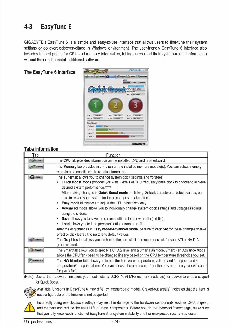
7/29/2019 GA-P55-UD3 Manual
http://slidepdf.com/reader/full/ga-p55-ud3-manual 74/128
Unique Features - 74 -
4-3 EasyTune 6
GIGABYTE'sEasyTune6 isa simpleandeasy-to-useinterfacethatallowsusersto ne-tune theirsystem
settings or do overclock/overvoltage in Windows environment. The user-friendly EasyTune 6 interface also
includes tabbed pages for CPU and memory information, letting users read their system-related information
without the need to install additional software.
The EasyTune 6 Interface
Tabs Information
Available functions in EasyTune 6 may differ by motherboard model. Grayed-out area(s) indicates that the item is
notcongurableorthefunctionisnotsupported.
(Note) Due to the hardware limitation, you must install a DDR3 1066 MHz memory module(s) (or above) to enable support
for Quick Boost.
Incorrectly doing overclock/overvoltage may result in damage to the hardware components such as CPU, chipset,
and memory and reduce the useful life of these components. Before you do the overclock/overvoltage, make sure
that you fully know each function of EasyTune 6, or system instability or other unexpected results may occur.
Tab FunctionThe CPU tab provides information on the installed CPU and motherboard.
The Memory tab provides information on the installed memory module(s). You can select memory
moduleonaspecicslottoseeitsinformation.The Tuner tab allows you to change system clock settings and voltages.
• Quick Boost mode provides you with 3 levels of CPU frequency/base clock to choose to achieve
desired system performance. (Note)
After making changes in Quick Boost mode or clicking Default to restore to default values, be
sure to restart your system for these changes to take effect.
• Easy mode allows you to adjust the CPU base clock only.
• Advanced mode allows you to individually change system clock settings and voltages settings
using the sliders.
• Saveallowsyoutosavethecurrentsettingstoanewprole(.txtle).
• Loadallowsyoutoloadprevioussettingsfromaprole.
After making changes in Easy mode/Advanced mode, be sure to click Set for these changes to takeeffect or click Default to restore to default values.
The Graphics tab allows you to change the core clock and memory clock for your ATI or NVIDIA
graphics card.
The Smart tab allows you to specify a C.I.A.2 level and a Smart Fan mode. Smart Fan Advance Mode
allows the CPU fan speed to be changed linearly based on the CPU temperature thresholds you set.
The HW Monitor tab allows you to monitor hardware temperature, voltage and fan speed and set
temperature/fan speed alarm. You can choose the alert sound from the buzzer or use your own sound
le(.wavle).

7/29/2019 GA-P55-UD3 Manual
http://slidepdf.com/reader/full/ga-p55-ud3-manual 75/128
- 75 - Unique Features
4-4 Dynamic Energy Saver ™ 2
GIGABYTE Dynamic Energy Saver ™ 2 (Note 1) is a revolutionary technology that delivers unparalleled power
savings with a click of the button. Featuring an advanced proprietary hardware and software design, GIGA-
BYTE Dynamic Energy Saver
™
2isabletoprovideexceptionalpowersavingsandenhancedpowerefciencywithoutsacricingcomputingperformance.
The Dynamic Energy Saver ™ 2 Interface
A. Meter Mode
In Meter Mode, GIGABYTE Dynamic Energy Saver ™ 2 shows how much power they have saved in a set pe-
riod of time.
• The above data is for reference only. Actual performance may vary depending on motherboard model.
• CPU Power and Power Scores are for reference only. Actual results may vary based on testing method.
Meter Mode - Button Information TableButton Description
1 Dynamic Energy Saver On/Off Switch (Default: Off)
2 Current CPU Power Consumption
3 Power Saving (Calculate power savings based on time)
4 Meter Time
5 Meter/Timer Reset Switch
6 Total Mode Switch
7 Meter Mode Switch
8 Dynamic Power Phase Status
9 Power Saving Status (Icons of the devices currently in power-saving mode will light on)
10 3-Level Power Saving Switch (Default:1) (Note 2)
11 Advanced Settings
12 Close (Application will enter Stealth Mode)
13 Minimize (Application will continue to run in taskbar)
14 INFO/Help
15 Motherboard Phase LED On/Off Switch (Default: On)
16 Live Utility Update (Check for the latest utility version)
1
10
2
3
45
678
9
11
12 13 14
16
15
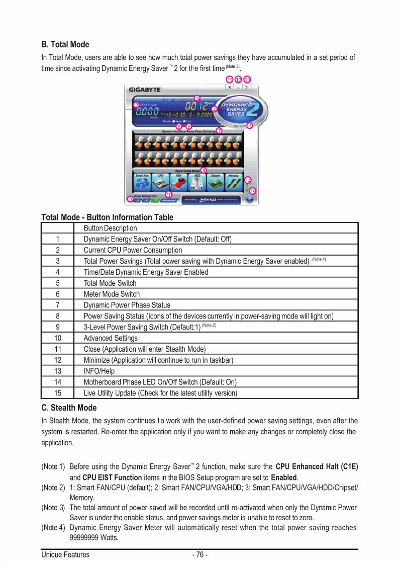
7/29/2019 GA-P55-UD3 Manual
http://slidepdf.com/reader/full/ga-p55-ud3-manual 76/128
Unique Features - 76 -
B. Total Mode
In Total Mode, users are able to see how much total power savings they have accumulated in a set period of
time since activating Dynamic Energy Saver ™ 2 for thersttime (Note 3).
(Note 1) Before using the Dynamic Energy Saver ™ 2 function, make sure the CPU Enhanced Halt (C1E)
and CPU EIST Function items in the BIOS Setup program are set to Enabled.
(Note 2) 1: Smart FAN/CPU (default); 2: Smart FAN/CPU/VGA/HDD; 3: Smart FAN/CPU/VGA/HDD/Chipset/
Memory.(Note 3) The total amount of power saved will be recorded until re-activated when only the Dynamic Power
Saver is under the enable status, and power savings meter is unable to reset to zero.
(Note 4) Dynamic Energy Saver Meter will automatically reset when the total power saving reaches
99999999 Watts.
C. Stealth Mode
In Stealth Mode, the system continues toworkwiththeuser-denedpowersavingsettings,evenafterthe
system is restarted. Re-enter the application only if you want to make any changes or completely close the
application.
Total Mode - Button Information TableButton Description
1 Dynamic Energy Saver On/Off Switch (Default: Off)
2 Current CPU Power Consumption
3 Total Power Savings (Total power saving with Dynamic Energy Saver enabled) (Note 4)
4 Time/Date Dynamic Energy Saver Enabled
5 Total Mode Switch
6 Meter Mode Switch7 Dynamic Power Phase Status
8 Power Saving Status (Icons of the devices currently in power-saving mode will light on)
9 3-Level Power Saving Switch (Default:1) (Note 2)
10 Advanced Settings
11 Close (Application will enter Stealth Mode)
12 Minimize (Application will continue to run in taskbar)
13 INFO/Help
14 Motherboard Phase LED On/Off Switch (Default: On)
15 Live Utility Update (Check for the latest utility version)
1
10
23
4
567
8
9
11 12 13
15
14
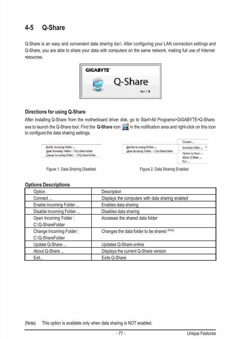
7/29/2019 GA-P55-UD3 Manual
http://slidepdf.com/reader/full/ga-p55-ud3-manual 77/128
- 77 - Unique Features
4-5 Q-Share
Q-Share is an easy and convenient data sharing tool.AfterconguringyourLANconnectionsettingsand
Q-Share, you are able to share your data with computers on the same network, making full use of Internet
resources.
Directions for using Q-Share
After installing Q-Share from the motherboard driver disk, go to Start>All Programs>GIGABYTE>Q-Share.
exe to launch the Q-Share tool. Find the Q-Share icon inthenoticationareaandright-clickonthisicon
tocongurethedatasharingsettings.
(Note) This option is available only when data sharing is NOT enabled.
Figure 1. Data Sharing Disabled Figure 2. Data Sharing Enabled
Options Descriptions
Option Description
Connect ... Displays the computers with data sharing enabled
Enable Incoming Folder ... Enables data sharing
Disable Incoming Folder ... Disables data sharing
Open Incoming Folder : Accesses the shared data folder
C:\Q-ShareFolder
Change Incoming Folder : Changes the data folder to be shared (Note)
C:\Q-ShareFolder Update Q-Share ... Updates Q-Share online
About Q-Share ... Displays the current Q-Share version
Exit... Exits Q-Share

7/29/2019 GA-P55-UD3 Manual
http://slidepdf.com/reader/full/ga-p55-ud3-manual 78/128
Unique Features - 78 -
4-6 Smart 6™
GIGABYTE Smart 6™ (Note 1) is designed with user-friendliness in mind, and offers a combination of 6 innovative
software utilities that provide easier and smarter PC system management. Smart 6™ allows you to speed up
systemperformance,reduceboot-uptime,manageasecureplatformandrecoverspeciedleseasilywithaclick of the mouse button.
Instructions:
Select a CPU performance boost level and restart your computer for
the changes to take effect.
SMART QuickBoost
SMART QuickBoost features quick and effortless CPU overclocking for novice and experienced
users alike; users simply click on one of the three levels of CPU performance enhancement, and
SMART QuickBoost automatically adjusts CPU performance.
Instructions:
Select the Enable check box below the BIOS QuickBoot or OS
QuickBoot item and then click Save to save the settings.
SMART QuickBoot
SMART QuickBoot speeds up the system boot-up process and shortens the waiting time for en-
teringtheoperatingsystem,deliveringgreaterefciencyfordailyuse.

7/29/2019 GA-P55-UD3 Manual
http://slidepdf.com/reader/full/ga-p55-ud3-manual 79/128
- 79 - Unique Features
SMART Recovery
WithSMARTRecovery,userscanquicklycreatebackupsofchangeddatales (Note 2) or copy
lesfromaspecicbackuponPATAandSATAharddrives(partitionedonNTFSlesystem)in
Windows Vista.
SMART DualBIOS
SMART DualBIOS is a new feature that can record personal passwords and important dates,
and remind users of the dates. It also stores the recorded data in the main and backup BIOS
simultaneously, which can prevent loss of the data in case the system/hard drive fails.
Instructions for copying les/folders from a backup:
To browse through your backups made at different time, select a
backup time using the time scroll bar on the right or at the bottom of
thescreen.Ifyouwanttocopybackale/folder,selectthele/folder
you wish to copy and click the Copy button.
Button Function
Enable Enables automatic daily backup (Note 3)
Schedule Sets a daily backup schedule
Capacity Sets the percentage of hard drive space used for
saving backups (Note 4)
•The hard drive must have more than 1 GB of capacity.
• Each partition can accommodate up to 64 backups (the actual
limit depends on the size of each partition). When this limit is
reached, the oldest backup will be ovewritten.
Theles/folderslistedonthescreenareread-onlysoyoucannotedittheir contents.
Instructions:Enter the Smart 6™ password to launch the SMART DualBIOS utility.
You can record personal passwords and important dates and set re-
minders of these dates. Click Save to save the settings and click Exit
to exit.
Instructions:
In the main menu, click the Cong button to open the Smart Recov-
ery Preference dialog box.
The Smart Recovery Preference dialog box:

7/29/2019 GA-P55-UD3 Manual
http://slidepdf.com/reader/full/ga-p55-ud3-manual 80/128
Unique Features - 80 -
(Note 1) When launching Smart 6™forthersttime,thesystemwillrequestyoutosetupapassword.Thispasswordisrequiredwhen
you activate SMART DualBIOS or when you want to make changes to the SMART Recorder or SMART TimeLock settings.
(Note2) Thechangeddatareferstothedatathathasbeenmodied,deleted,ornewlyaddedsincethelastbackup.
(Note 3) The system will make an automatic backup on changed data only once everyday. If the computer is turned on for
a long time, the backup will be performed at the scheduled backup time. If the computer is turned off before the
scheduled backup time, the backup will be performed on the next boot.
(Note 4) We recommend that you preserve at least 25 percent of the hard drive space to optimize the storage space for
the backups. The backups of the changed data will be stored in the original partition of the data.
(Note 5) You will not be able to use the "Safely Remove Hardware" feature in the operating system with SMART Recorder
enabled. To remove an external storage device, unplug it directly from your computer (please note that doing so
may result in damage to the hardware device or loss of data).
(Note 6) You can set the User Password in the system BIOS Setup program to prevent the system time being changed by other users.
Instructions:Select the Enable check box at the bottom of the ON/OFF Recorder
or File Monitor tab to enable the recording of system on/off time or
lescopying.EnteringtheSmart6™ password is required before you
make any changes to the previous settings.
Instructions (Note 6):
Click the lock icon on the bottom left corner and enter the Smart 6™
password. Set the time when a user can or cannot use your computer
for weekdays and weekends. Click Save to save the settings and
click Exit to exit.
The Smart TimeLock Alert:
An alert will appear 15 minutes and 1 minute prior to the default shutdown time.
When the alert appears, you can enter the Smart 6 ™ password to extend the
usage time or click Cancel to close the alert. If you respond Cancel, you will
be requested to enter the password to extend the usage time again when thedefault shutdown time arrives, or the computer will shutdown right away.
SMART Recorder
SMART Recorder monitors and records the activities in a system such as the time when the
computerwasturnedon/offorevenwhenlargedatalesweremovedwithintheharddriveor
copied to an external storage device (Note 5).
SMART TimeLock
SMART TimeLock allows users to effectively manage computer usage time with simple rules and
options.

7/29/2019 GA-P55-UD3 Manual
http://slidepdf.com/reader/full/ga-p55-ud3-manual 81/128
- 81 - Unique Features
4-7 Smart TPM j
GIGABYTE's unique Smart TPM (Trusted Platform Module) supports the industry's most advanced hardware-
based data encryption. Smart TPM provides users with an easy-to-use software interface to create a portable
userkeyusingaBluetoothcellphoneorUSBashdrive.Userscanaccess/closetheirPSDdatabysimply
connectingtotheBluetoothcellphoneorpluggingintheUSBashdrive,withoutthehasslesofcomplicatedcongurations.Inaddition,userscancreatemorethanoneBluetoothcellphone/USBashdrivekey,sowhen
they lost a key they still can access data.
A. Before installing Smart TPM, follow the steps below in sequence:Step 1:
As the computer starts, enter the BIOS Setup program. Go to the Security Chip Conguration menu and set Security Chip to Enabled/Activate. It's recommended that you use the Clear Security Chip setting (press <Ctrl> + <F1> in the BIOS main
menu to display this setting) to clear the TPM chip. Save changes and then restart your computer.
B. Instructions for using Smart TPM:
Step 2:
InstalltheInneonTPMdriverfromthemotherboarddriverdisk(selectInneon TPM Driver ).
Step 3:
Install the Smart TPM utility from the motherboard driver disk. (Click the tab at the bottom of the left pane of the autorun
screen and you'll be directed to the Install New Utilities menu. Click the Install button on the right of Smart TPM to install it.)
j Only for GA-P55-UD3P.
1. Afterconguringtheabovesettingsandrestartingyourcomputer,theInneonSecurityPlatformicon , whichindicatesthattheInneonSecurityPlatformisnotyetinitialized,willappearinthenoticationarea.Double-
click the icon or right-click the Smart TPM icon and select Initialization Wizard to access Smart TPM.
You can select Advanced modetoentertheInneonSecurityPlatformSettingsTooltocongureadvancedsettings.
(YouhavetoatleastsetupaPersonalSecureDrive(PSD).RefertotheInneonSecurityPlatformHelpletosee
how to set up the PSD.)
• After creating the password(s) and key(s) associated the TPM, be sure to store them in a secure locationand back them up. Loss of the password(s) or the key(s) will render the les encrypted via the TPM unableto be cracked or read.
• Though the TPM delivers the latest data security technology, it does not guarantee data integrity or providehardware protection. GIGABYTE is not liable for loss of encrypted data as a result of hardware damage.
• Previously encrypted les will become inaccessible after the TPM chip is cleared. Be sure to back up theencrypted les rst.
• To prevent the TPM settings being cleared by other users, we recommend that you set the User Passwordin the BIOS Setup program.
2. The easy-to-use Smart TPM interface allows users to easily ini-tializetheTPMchip,setuptheTPMUserPassword,congurea Personal Secure Drive, and create a portable user key.
Set Your TPM PasswordA password is automatically provided. You can change it to your own password. Be sure to memorize this password because it al-lows you to create a portable user key using your Bluetooth cellphoneorUSBashdrive.
Set up your Personal Secure Drive(PSD) CongureaPersonalSecureDrive(PSD)here.SpecifythePSD
drive letter, drive label, size, and a local drive on which your PSDwill be saved.
Create Your Smart TPM Key SetyourBluetoothcellphone/USBashdriveastheSmartTPM
user key. You will be able to access/close your PSD data when
connecting to the Bluetooth cell phone or when plugging in the USBashdrivethatisconguredastheSmartTPMuserkey.Selectingthe Enable Backup to BIOS check box will store the encryptedTPM User Password in the system BIOS.
3. Click OK to complete the settings.

7/29/2019 GA-P55-UD3 Manual
http://slidepdf.com/reader/full/ga-p55-ud3-manual 82/128
Unique Features - 82 -

7/29/2019 GA-P55-UD3 Manual
http://slidepdf.com/reader/full/ga-p55-ud3-manual 83/128
- 83 - Appendix
Chapter 5 Appendix
5-1 Conguring SATA Hard Drive(s)
To congure SATA hard drive(s), follow the steps below:A. Install SATA hard drive(s) in your computer.
B. CongureSATAcontrollermodeinBIOSSetup.
C. CongureaRAIDarrayinRAIDBIOS. (Note 1)
D. MakeaoppydiskcontainingtheSATARAID/AHCIdriverforWindowsXP. (Note 2)
E. Install the SATA RAID/AHCI driver and operating system. (Note 2)
Before you begin
Please prepare:
• At least two SATA hard drives (to ensure optimal performance, it is recommended that you use two hard
drives with identical model and capacity). If you do not want to create RAID, you may prepare only one
hard drive.
• Anemptyformattedoppydisk.
•Windows Vista/XP setup disk.
•Motherboard driver disk.
5-1-1 Conguring Intel P55 SATA Controllers
A. Installing SATA hard drive(s) in your computer
Attach one end of the SATA signal cable to the rear of the SATA hard drive and the other end to available
SATA port on the motherboard. If there is more than one SATA controller on your motherboard, refer to
"Chapter 1," "Hardware Installation," to identify the SATA controller for the SATA port. (For example, on this
motherboard, the SATA2_0, SATA2_1, SATA2_2, SATA2_3, SATA2_4 and SATA2_5 ports are supported by
P55 Chipset.) Then connect the power connector from your power supply to the hard drive.
(Note 1) Skip this step if you do not want to create RAID array.
(Note 2) Required when the SATA controller is set to AHCI or RAID mode.

7/29/2019 GA-P55-UD3 Manual
http://slidepdf.com/reader/full/ga-p55-ud3-manual 84/128
Appendix - 84 -
B. Conguring SATA controller mode in BIOS Setup
MakesuretoconguretheSATAcontrollermodecorrectlyinsystemBIOSSetup.
Step 1:
Turn on your computer and press <Delete> to enter BIOS Setup during the POST (Power-On Self-Test).
To create RAID, set SATA RAID/AHCI Mode under the Integrated Peripherals menu to RAID (Figure 1)
(Disabled by default). If you do not want to create RAID, set this item to Disabled or AHCI.
Step 2:
Save changes and exit BIOS Setup.
Figure 1
The BIOS Setup menus described in this section may differ from the exact settings for your moth-
erboard. The actual BIOS Setup menu options you will see shall depend on the motherboard you
have and the BIOS version.
CMOS Setup Utility-Copyright (C) 1984-2009 Award Software
Integrated Peripherals
SATA RAID/AHCI Mode [RAID]
SATA Port0-3 Native Mode [Enabled]
USB Controllers [Enabled]
USB Legacy Function [Enabled]
USB Storage Function [Enabled]
Azalia Codec [Auto]
Onboard H/W LAN [Enabled]
Green LAN [Disabled]
SMART LAN [Press Enter]Onboard LAN Boot ROM [Disabled]
eSATA Controller [Enabled]
eSATA Ctrl Mode [IDE]
GSATA 0_1/IDE Controller [Enabled]
GSATA 0_1/IDE Ctrl Mode [IDE]
Onboard Serial Port 1 [3F8/IRQ4]
Onboard Parallel Port [378/IRQ7]
Parallel Port Mode [SPP]
higf: Move Enter: Select +/-/PU/PD: Value F10: Save ESC: Exit F1: General Help
F5: Previous Values F6: Fail-Safe Defaults F7: Optimized Defaults
Item Help
Menu Level
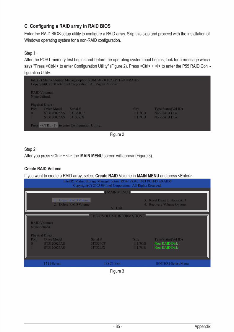
7/29/2019 GA-P55-UD3 Manual
http://slidepdf.com/reader/full/ga-p55-ud3-manual 85/128
- 85 - Appendix
C. Conguring a RAID array in RAID BIOS
EntertheRAIDBIOSsetuputilitytocongureaRAIDarray.Skipthisstepandproceedwiththeinstallationof
Windowsoperatingsystemforanon-RAIDconguration.
Step 1:
After the POST memory test begins and before the operating system boot begins, look for a message which
says"Press<Ctrl-I>toenterCongurationUtility"(Figure2).Press<Ctrl>+<I>toentertheP55RAIDCon -
gurationUtility.
Figure 2
Step 2:
After you press <Ctrl> + <I>, the MAIN MENU screen will appear (Figure 3).
Create RAID Volume
If you want to create a RAID array, select Create RAID Volume in MAIN MENU and press <Enter>.
Figure 3
Intel(R) Matrix Storage Manager option ROM v8.9.0.1023 PCH-D wRAID5
Copyright(C) 2003-09 Intel Corporation. All Rights Reserved.
RAID Volumes :
Nonedened.
Physical Disks :
Port Drive Model Serial # Size Type/Status(Vol ID)
0 ST3120026AS 3JT354CP 111.7GB Non-RAID Disk
1 ST3120026AS 3JT329JX 111.7GB Non-RAID Disk
Press<CTRL-I>toenterCongurationUtility..
Intel(R) Matrix Storage Manager option ROM v8.9.0.1023 PCH-D wRAID5
Copyright(C) 2003-09 Intel Corporation. All Rights Reserved.
3. Reset Disks to Non-RAID
4. Recovery Volume Options
RAID Volumes :
Nonedened.
Physical Disks :
Port Drive Model Serial # Size Type/Status(Vol ID)
0 ST3120026AS 3JT354CP 111.7GB Non-RAID Disk
1 ST3120026AS 3JT329JX 111.7GB Non-RAID Disk
[hi]-Select [ESC]-Exit [ENTER]-Select Menu
[ DISK/VOLUME INFORMATION ]
[ MAIN MENU ]
1. Create RAID Volume
2. Delete RAID Volume5. Exit
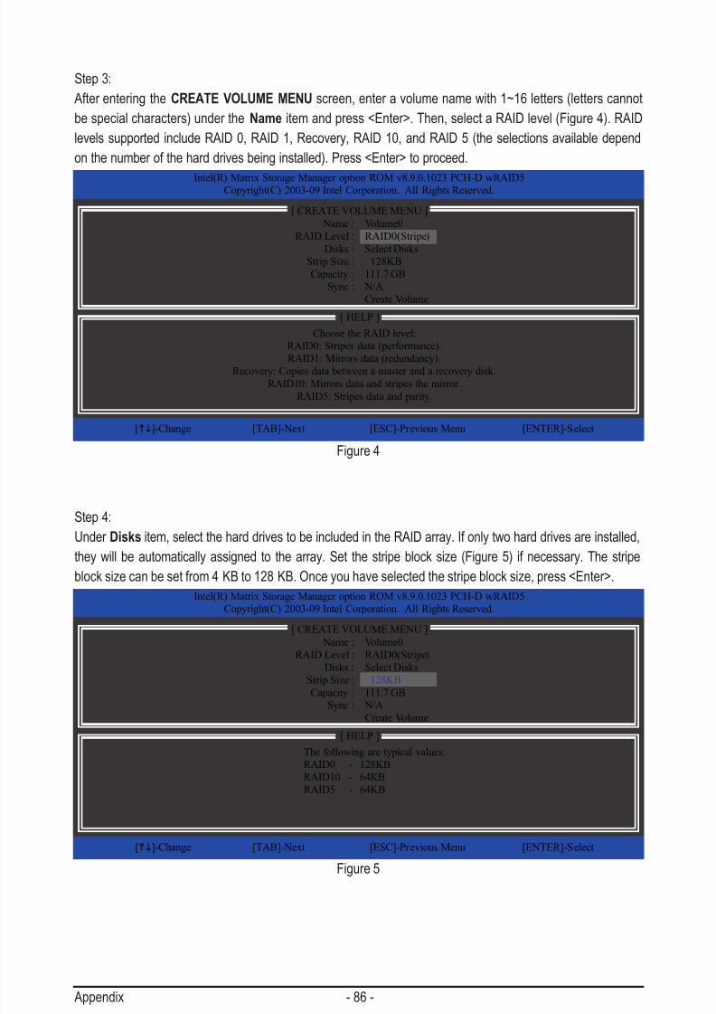
7/29/2019 GA-P55-UD3 Manual
http://slidepdf.com/reader/full/ga-p55-ud3-manual 86/128
Appendix - 86 -
Step 3:
After entering the CREATE VOLUME MENU screen, enter a volume name with 1~16 letters (letters cannot
be special characters) under the Name item and press <Enter>. Then, select a RAID level (Figure 4). RAID
levels supported include RAID 0, RAID 1, Recovery, RAID 10, and RAID 5 (the selections available depend
on the number of the hard drives being installed). Press <Enter> to proceed.
Step 4:
Under Disks item, select the hard drives to be included in the RAID array. If only two hard drives are installed,they will be automatically assigned to the array. Set the stripe block size (Figure 5) if necessary. The stripe
block size can be set from 4 KB to 128 KB. Once you have selected the stripe block size, press <Enter>.
Figure 4
Figure 5
Intel(R) Matrix Storage Manager option ROM v8.9.0.1023 PCH-D wRAID5Copyright(C) 2003-09 Intel Corporation. All Rights Reserved.
Choose the RAID level:
RAID0: Stripes data (performance).
RAID1: Mirrors data (redundancy).Recovery: Copies data between a master and a recovery disk.
RAID10: Mirrors data and stripes the mirror.
RAID5: Stripes data and parity.
[hi]-Change [TAB]-Next [ESC]-Previous Menu [ENTER]-Select
[ HELP ]
Name : Volume0
RAID Level : RAID0(Stripe)
Disks : Select Disks
Strip Size : 128KB
Capacity : 111.7 GB
Sync : N/A
Create Volume
[ CREATE VOLUME MENU ]
Intel(R) Matrix Storage Manager option ROM v8.9.0.1023 PCH-D wRAID5
Copyright(C) 2003-09 Intel Corporation. All Rights Reserved.
The following are typical values:
RAID0 - 128KB
RAID10 - 64KB
RAID5 - 64KB
[hi]-Change [TAB]-Next [ESC]-Previous Menu [ENTER]-Select
[ HELP ]
Name : Volume0
RAID Level : RAID0(Stripe)
Disks : Select Disks
Strip Size : 128KB
Capacity : 111.7 GB
Sync : N/A
Create Volume
[ CREATE VOLUME MENU ]
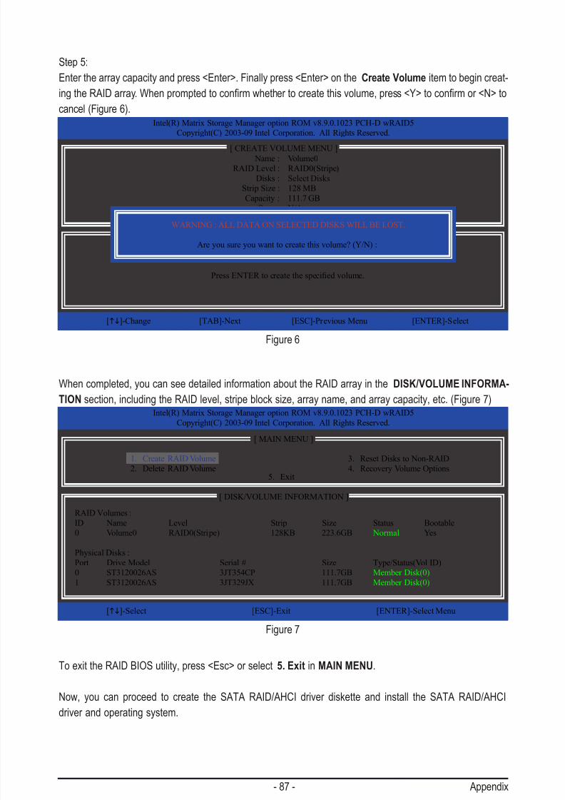
7/29/2019 GA-P55-UD3 Manual
http://slidepdf.com/reader/full/ga-p55-ud3-manual 87/128
- 87 - Appendix
Step 5:
Enter the array capacity and press <Enter>. Finally press <Enter> on the Create Volume item to begin creat-
ingtheRAIDarray.Whenpromptedtoconrmwhethertocreatethisvolume,press<Y>toconrmor<N>to
cancel (Figure 6).
When completed, you can see detailed information about the RAID array in the DISK/VOLUME INFORMA-
TION section, including the RAID level, stripe block size, array name, and array capacity, etc. (Figure 7)
To exit the RAID BIOS utility, press <Esc> or select 5. Exit in MAIN MENU.
Now, you can proceed to create the SATA RAID/AHCI driver diskette and install the SATA RAID/AHCIdriver and operating system.
Figure 6
Figure 7
Intel(R) Matrix Storage Manager option ROM v8.9.0.1023 PCH-D wRAID5
Copyright(C) 2003-09 Intel Corporation. All Rights Reserved.
PressENTERtocreatethespeciedvolume.
[hi]-Change [TAB]-Next [ESC]-Previous Menu [ENTER]-Select
[ HELP ]
Name : Volume0
RAID Level : RAID0(Stripe)
Disks : Select Disks
Strip Size : 128 MB
Capacity : 111.7 GB
Sync : N/A
Create Volume
[ CREATE VOLUME MENU ]
WARNING : ALL DATA ON SELECTED DISKS WILL BE LOST.
Are you sure you want to create this volume? (Y/N) :
Intel(R) Matrix Storage Manager option ROM v8.9.0.1023 PCH-D wRAID5
Copyright(C) 2003-09 Intel Corporation. All Rights Reserved.
3. Reset Disks to Non-RAID
4. Recovery Volume Options
RAID Volumes :
ID Name Level Strip Size Status Bootable
0 Volume0 RAID0(Stripe) 128KB 223.6GB Normal Yes
Physical Disks :
Port Drive Model Serial # Size Type/Status(Vol ID)0 ST3120026AS 3JT354CP 111.7GB Member Disk(0)
1 ST3120026AS 3JT329JX 111.7GB Member Disk(0)
[hi]-Select [ESC]-Exit [ENTER]-Select Menu
[ DISK/VOLUME INFORMATION ]
[ MAIN MENU ]
1. Create RAID Volume
2. Delete RAID Volume5. Exit

7/29/2019 GA-P55-UD3 Manual
http://slidepdf.com/reader/full/ga-p55-ud3-manual 88/128
Appendix - 88 -
Recovery Volume Options
Intel Rapid Recover Technology provides data protection by allowing users to easily restore data and system
operation using a designated recovery drive. With the Rapid Recovery Technology, which employs RAID 1
functionality, users can copy the data from the master drive to the recovery drive; if needed, the data on the
recovery drive can be restored back to the master drive.
Before you begin:
•The recovery drive must have equal or greater capacity than the master drive.
• A recovery volume can be created with two hard drives only. A recovery volume and a RAID array cannot
co-exist in the system at the same time, that is, if you have already created a recovery volume, you are
unable to create a RAID array.
•Only the master drive can be riewed in the operating system; the recovery drive is hidden.
Step 1:
select Create RAID Volume in MAIN MENU and press <Enter> (Figure 8).
Intel(R) Matrix Storage Manager option ROM v8.9.0.1023 PCH-D wRAID5
Copyright(C) 2003-09 Intel Corporation. All Rights Reserved.
3. Reset Disks to Non-RAID
4. Recovery Volume Options
RAID Volumes :
Nonedened.
Physical Disks :
Port Drive Model Serial # Size Type/Status(Vol ID)
0 ST3120026AS 3JT354CP 111.7GB Non-RAID Disk
1 ST3120026AS 3JT329JX 111.7GB Non-RAID Disk
[hi]-Select [ESC]-Exit [ENTER]-Select Menu
[ DISK/VOLUME INFORMATION ]
[ MAIN MENU ]
1. Create RAID Volume
2. Delete RAID Volume5. Exit
Figure 8
Intel(R) Matrix Storage Manager option ROM v8.9.0.1023 PCH-D wRAID5
Copyright(C) 2003-09 Intel Corporation. All Rights Reserved.
Choose the RAID level:
RAID0: Stripes data (performance).
RAID1: Mirrors data (redundancy).
Recovery: Copies data between a master and a recovery disk.RAID10: Mirrors data and stripes the mirror.
RAID5: Stripes data and parity.
[hi]-Change [TAB]-Next [ESC]-Previous Menu [ENTER]-Select
[ HELP ]
Name : Volume0
RAID Level : Recovery
Disks : Select Disks
Strip Size : N/A
Capacity : 0.0 GB
Sync : Continuous
Create Volume
[ CREATE VOLUME MENU ]
Figure 9
Step 2:
After entering the volume name, select Recovery under the RAID Level item and press <Enter> (Figure 9).

7/29/2019 GA-P55-UD3 Manual
http://slidepdf.com/reader/full/ga-p55-ud3-manual 89/128
- 89 - Appendix
Figure 10
Step 3:
Press <Enter> under the Select Disks item. In the SELECT DISKS box, press <Tab> on the hard drive you
want to use for the master drive and press <Space> on the hard drive you want to use for the recovery drive.
(Make sure the recovery drive has equal or larger capacity than the master drive.) Then press <Enter> to
conrm.(Figure10)
Intel(R) Matrix Storage Manager option ROM v8.9.0.1023 PCH-D wRAID5Copyright(C) 2003-09 Intel Corporation. All Rights Reserved.
Choose the RAID level:
RAID0: Stripes data (performance).
RAID1: Mirrors data (redundancy).Recovery: Copies data between a master and a recovery disk.
RAID10: Mirrors data and stripes the mirror.
RAID5: Stripes data and parity.
[hi]-Change [TAB]-Next [ESC]-Previous Menu [ENTER]-Select
[ HELP ]
[ CREATE VOLUME MENU ]
Name : Volume0
RAID Level : Recovery
Disks : Select Disks
Strip Size : 128KB
Capacity : 223.6 GB
Create Volume
[ SELECT DISKS ]
[hi]-Prev/Next [TAB]-(M)aster [SPACE]-(R)ecovery [ENTER]-Done
Port Drive Model Serial # Size Type/Status
M0 ST3120026AS 3JT354CP 111.7GB Non-RAID Disk
R 1 ST3120026AS 3JT329JX 111.7GB Non-RAID Disk
Select 1 Master and 1 Recovery disk to create volume.
Step 4:
Under Sync, select Continuous or On Request (Figure 11). When set to Continuous, changes made to the
data on the master drive will be automatically and continuously copied to the recovery drive when both hard
drives are installed in the system. On Request allows users to update data from the master drive to the re-covery drive manually using the Update Volume function of the Intel Matrix Storage Console in the operating
system. On Request also allows users to restore the master drive to a previous state.
Intel(R) Matrix Storage Manager option ROM v8.9.0.1023 PCH-D wRAID5
Copyright(C) 2003-09 Intel Corporation. All Rights Reserved.
Select a sync option:
On Request: volume is updated manually
Continuous: volume is updated automatically
[hi]-Change [TAB]-Next [ESC]-Previous Menu [ENTER]-Select
[ HELP ]
Name : Volume0
RAID Level : Recovery
Disks : Select Disks
Strip Size : N/A
Capacity : 0.0 GB
Sync : Continuous
Create Volume
[ CREATE VOLUME MENU ]
Figure 11
Step 5:Finally press <Enter> on the Create Volume item to begin creating the Recovery Volume and follow the on-
screen instructions to complete.

7/29/2019 GA-P55-UD3 Manual
http://slidepdf.com/reader/full/ga-p55-ud3-manual 90/128
Appendix - 90 -
Delete RAID Volume
To delete a RAID array, select Delete RAID Volume in MAIN MENU and press <Enter>. In the DELETE
VOLUME MENU section, use the up or down arrow key to select the array to be deleted and press <Delete>.
Whenpromptedtoconrmyourselection(Figure12),press<Y>toconrmor<N>toabort.
Figure 12
Intel(R) Matrix Storage Manager option ROM v8.9.0.1023 PCH-D wRAID5
Copyright(C) 2003-09 Intel Corporation. All Rights Reserved.
Deleting a volume will reset the disks to non-RAID.
WARNING: ALL DISK DATA WILL BE DELETED.
(This does not apply to Recovery volumes)
[hi]-Select [ESC]-Exit [DEL]-Delete Volume
[ HELP ]
[ DELETE VOLUME MENU ]
Name Level Drives Capacity Status Bootable
Volume0 RAID0(Stripe) 2 223.6GB Normal Yes
ALL DATA IN THE VOLUME WILL BE LOST!
(This does not apply to Recovery volumes)
Are you sure you want to delete "Volume0"? (Y/N) :
[ DELETE VOLUME VERIFICATION ]

7/29/2019 GA-P55-UD3 Manual
http://slidepdf.com/reader/full/ga-p55-ud3-manual 91/128
- 91 - Appendix
5-1-2 Conguring JMB362/GIGABYTE SATA2 SATA Controller
A. Installing SATA hard drive(s) in your computer
Attach one end of the SATA signal cable to the rear of the SATA hard drive and the other end to available
SATA port on the motherboard. See the table below for the SATA controllers and their corresponding SATA
ports. Then connect the power connector from your power supply to the hard drive.
B. Conguring SATA controller mode in BIOS Setup
MakesuretoconguretheSATAcontrollermodecorrectlyinsystemBIOSSetup.
Step 1:
Turn on your computer and press <Delete> to enter BIOS Setup during the POST. In BIOS Setup, go to Inte-
grated Peripherals.ToenableRAID,seethetablebelowforconguringdifferentSATAControllersforRAID.
The BIOS Setup menus described in this section may differ from the exact settings for your moth-
erboard. The actual BIOS Setup menu options you will see shall depend on the motherboard you
have and the BIOS version.
Figure 1
Step 2:
Save changes and exit BIOS Setup.
Controller Connectors BIOS Settings
JMB362 eSATA ports Set eSATA Controller to Enabled
Set eSATA Ctrl Mode to RAID
GIGABYTE GSATA2_0/1 Set GSATA 0_1/IDE Controller to Enabled
SATA2 Set GSATA 0_1/IDE Ctrl Mode to RAID/IDE
CMOS Setup Utility-Copyright (C) 1984-2009 Award Software
Integrated Peripherals
higf: Move Enter: Select +/-/PU/PD: Value F10: Save ESC: Exit F1: General Help
F5: Previous Values F6: Fail-Safe Defaults F7: Optimized Defaults
Item Help
Menu LevelSATA RAID/AHCI Mode [Disabled]
SATA Port0-3 Native Mode [Enabled]
USB Controllers [Enabled]USB Legacy Function [Enabled]
USB Storage Function [Enabled]
Azalia Codec [Auto]
Onboard H/W LAN [Enabled]
Green LAN [Disabled]
SMART LAN [Press Enter]
Onboard LAN Boot ROM [Disabled]
eSATA Controller [Enabled]
eSATA Ctrl Mode [RAID]
GSATA 0_1/IDE Controller [Enabled]
GSATA 0_1/IDE Ctrl Mode [RAID/IDE]
Onboard Serial Port 1 [3F8/IRQ4]
Onboard Parallel Port [378/IRQ7]
Parallel Port Mode [SPP]

7/29/2019 GA-P55-UD3 Manual
http://slidepdf.com/reader/full/ga-p55-ud3-manual 92/128
Appendix - 92 -
C. Conguring a RAID array in RAID BIOS
EntertheRAIDBIOSsetuputilitytocongureaRAIDarray.Skipthisstepandproceedtotheinstallationof
Windowsoperatingsystemforanon-RAIDconguration.
After the POST memory test begins and before the operating system boot begins, look for a message which
says "Press <Ctrl-G> to enter RAID Setup Utility" (Figure 2). Press <Ctrl> + <G> to enter the RAID setup util-
ity.
GIGABYTE Technology Corp. PCI Express to SATAII HOST Controller ROM v1.07.06
Copyright (C) 2005-2009 Gigabyte Technology Corp. (http://www.gigabyte.com)
HDD0 : ST3120026AS 120 GB Non-RAID
HDD1 : ST3120026AS 120 GB Non-RAID
Press <Ctrl-G> to enter RAID Setup Utility ...
Figure 2
In the main screen of the RAID setup utility (Figure 3), use the up or down arrow key to highlight
through choices in the Main Menu block. Highlight the item that you wish to execute and press
<Enter>.
Note: In the main screen, you can select a hard drive in the Hard Disk Drive List block and press <Enter> to
see detailed information about the selected hard drive.
Figure 3
[fgTAB]-Switch Window [hi]-Select ITEM [ENTER]-Action [ESC]-Exit
[ RAID Disk Drive List ]
[ Main Menu ] [ Hard Disk Drive List ]
Gigabyte Technology Corp. RAID Setup Utility v1.07.06
Create RAID Disk DriveDelete RAID Disk DriveRevert HDD to Non-RAID
SolveMirrorConictRebuild Mirror DriveSave And Exit SetupExit Without Saving
Model Name Capacity Type/StatusHDD0: ST3120026AS 120 GB Non-RAIDHDD1: ST3120026AS 120 GB Non-RAID
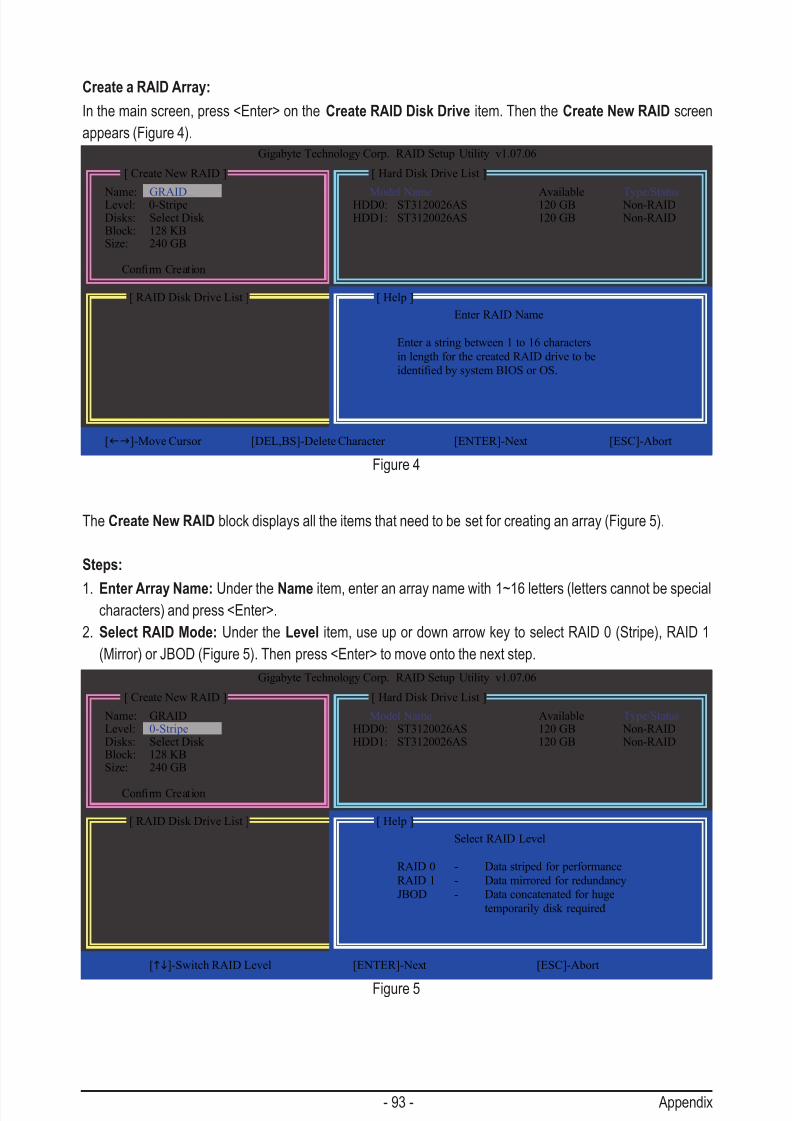
7/29/2019 GA-P55-UD3 Manual
http://slidepdf.com/reader/full/ga-p55-ud3-manual 93/128
- 93 - Appendix
Create a RAID Array:
In the main screen, press <Enter> on the Create RAID Disk Drive item. Then the Create New RAID screen
appears (Figure 4).
The Create New RAID block displays all the items that need to be set for creating an array (Figure 5).
Steps:
1. Enter Array Name: Under the Name item, enter an array name with 1~16 letters (letters cannot be specialcharacters) and press <Enter>.
2. Select RAID Mode: Under the Level item, use up or down arrow key to select RAID 0 (Stripe), RAID 1
(Mirror) or JBOD (Figure 5). Then press <Enter> to move onto the next step.
Figure 4
Figure 5
[ RAID Disk Drive List ]
[ Create New RAID ] [ Hard Disk Drive List ]
Gigabyte Technology Corp. RAID Setup Utility v1.07.06
Name: GRAID _
Level: 0-StripeDisks: Select Disk Block: 128 KBSize: 240 GB
ConrmCreation
Model Name Available Type/StatusHDD0: ST3120026AS 120 GB Non-RAIDHDD1: ST3120026AS 120 GB Non-RAID
[ Help ]
[fg]-Move Cursor [DEL,BS]-Delete Character [ENTER]-Next [ESC]-Abort
Enter RAID Name
Enter a string between 1 to 16 characters
in length for the created RAID drive to be
identiedbysystemBIOSorOS.
[ RAID Disk Drive List ]
[ Create New RAID ] [ Hard Disk Drive List ]
Gigabyte Technology Corp. RAID Setup Utility v1.07.06
Name: GRAIDLevel: 0-StripeDisks: Select Disk Block: 128 KBSize: 240 GB
ConrmCreation
Model Name Available Type/StatusHDD0: ST3120026AS 120 GB Non-RAIDHDD1: ST3120026AS 120 GB Non-RAID
[ Help ]
[hi]-Switch RAID Level [ENTER]-Next [ESC]-Abort
Select RAID Level
RAID 0 - Data striped for performance
RAID 1 - Data mirrored for redundancy
JBOD - Data concatenated for huge
temporarily disk required
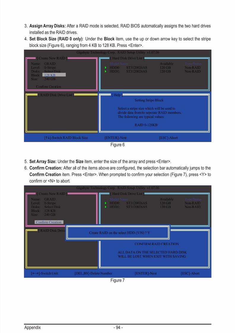
7/29/2019 GA-P55-UD3 Manual
http://slidepdf.com/reader/full/ga-p55-ud3-manual 94/128
Appendix - 94 -
3. Assign Array Disks: After a RAID mode is selected, RAID BIOS automatically assigns the two hard drives
installed as the RAID drives.
4. Set Block Size (RAID 0 only): Under the Block item, use the up or down arrow key to select the stripe
block size (Figure 6), ranging from 4 KB to 128 KB. Press <Enter>.
5. Set Array Size: Under the Size item, enter the size of the array and press <Enter>.
6. Conrm Creation:Afteralloftheitemsabovearecongured,theselectionbarautomaticallyjumpstothe
Conrm Creationitem.Press<Enter>.Whenpromptedtoconrmyourselection(Figure7),press<Y>toconrmor<N>toabort.
Figure 6
Figure 7
[ RAID Disk Drive List ]
[ Create New RAID ] [ Hard Disk Drive List ]
Gigabyte Technology Corp. RAID Setup Utility v1.07.06
Name: GRAIDLevel: 0-StripeDisks: Select Disk Block: 128 KBSize: 240 GB
ConrmCreation
Model Name Available Type/Status HDD0: ST3120026AS 120 GB Non-RAID HDD1: ST3120026AS 120 GB Non-RAID
[ Help ]
[hi]-Switch RAID Block Size [ENTER]-Next [ESC]-Abort
Setting Stripe Block
Select a stripe size which will be used to
divide data from/to seperate RAID members.
The following are typical values:
RAID 0-128KB
[ RAID Disk Drive List ]
[ Create New RAID ] [ Hard Disk Drive List ]
Gigabyte Technology Corp. RAID Setup Utility v1.07.06
Name: GRAIDLevel: 0-StripeDisks: Select Disk Block: 128 KBSize: 240 GB
ConrmCreation
Model Name Available Type/Status HDD0: ST3120026AS 120 GB Non-RAID HDD1: ST3120026AS 120 GB Non-RAID
[ Help ]
[fg]-Switch Unit [DEL,BS]-Delete Number [ENTER]-Next [ESC]-Abort
CONFIRM RAID CREATION
ALL DATA ON THE SELECTED HARD DISK
WILL BE LOST WHEN EXIT WITH SAVING
Create RAID on the select HDD (Y/N) ? Y

7/29/2019 GA-P55-UD3 Manual
http://slidepdf.com/reader/full/ga-p55-ud3-manual 95/128
- 95 - Appendix
Whennished,thenewRAIDarraywillbedisplayedintheRAID Disk Drive List block (Figure 8).
Figure 8
Model Name RAID Level Capacity Status Members(HDDx)
RDD0: GRAID 0-Stripe 240 GB Normal 01
[fgTAB]-Switch Window [hi]-Select ITEM [ENTER]-Action [ESC]-Exit
[ RAID Disk Drive List ]
[ Main Menu ] [ Hard Disk Drive List ]
Gigabyte Technology Corp. RAID Setup Utility v1.07.06
Create RAID Disk DriveDelete RAID Disk DriveRevert HDD to Non-RAIDSolveMirrorConict
Rebuild Mirror DriveSave And Exit SetupExit Without Saving
Model Name Capacity Type/StatusHDD0: ST3120026AS 120 GB RAID InsideHDD1: ST3120026AS 120 GB RAID Inside
To check more detailed information about the array, use the <Tab> key while in the Main Menu block to move
the selection bar to the RAID Disk Drive List block. Select the array and press <Enter>. A small window dis-
playing the array information will appear in the center of the screen (Figure 9).
Figure 9
Model Name RAID Level Capacity Status Members(HDDx)
RDD0: GRAID 0-Stripe 240 GB Normal 01
[fgTAB]-Switch Window [hi]-Select RAID [ENTER]-Detail [ESC]-Exit
[ RAID Disk Drive List ]
[ Main Menu ] [ Hard Disk Drive List ]
Gigabyte Technology Corp. RAID Setup Utility v1.07.06
Create RAID Disk Drive
Delete RAID Disk DriveRevert HDD to Non-RAIDSolveMirrorConictRebuild Mirror DriveSave And Exit SetupExit Without Saving
Model Name Capacity Type/Status
HDD0: ST3120026AS 120 GB RAID InsideHDD1: ST3120026AS 120 GB RAID Inside
Name: GRAID
Level: 0-Stripe
Block: 128 KB
Capacity: 240 GB
Members: HDD 01
Status: Normal
[ RAID Information ]

7/29/2019 GA-P55-UD3 Manual
http://slidepdf.com/reader/full/ga-p55-ud3-manual 96/128
Appendix - 96 -
Model Name RAID Level Capacity Status Members(HDDx)
RDD0: GRAID 0-Stripe 240 GB Normal 01
[fgTAB]-Switch Window [hi]-Select ITEM [ENTER]-Action [ESC]-Exit
[ RAID Disk Drive List ]
[ Main Menu ] [ Hard Disk Drive List ]
Gigabyte Technology Corp. RAID Setup Utility v1.07.06
Create RAID Disk DriveDelete RAID Disk Drive
Revert HDD to Non-RAIDSolveMirrorConictRebuild Mirror DriveSave And Exit SetupExit Without Saving
Model Name Capacity Type/StatusHDD0: ST3120026AS 120 GB RAID Inside
HDD1: ST3120026AS 120 GB RAID Inside
7. Save and Exit Setup:AfterconguringtheRAIDarray,selecttheSave And Exit Setup item in the main
screen to save your settings before exiting the RAID BIOS utility, then press <Y> (Figure 10).
Model Name RAID Level Capacity Status Members(HDDx)
RDD0: GRAID 0-Stripe 240 GB Normal 01
[hi]-SelectRAID [SPACE]-MarkDelete [DEL]-Conrm [ESC]-Abort
[ RAID Disk Drive List ]
[ Main Menu ] [ Hard Disk Drive List ]
Gigabyte Technology Corp. RAID Setup Utility v1.07.06
Create RAID Disk DriveDelete RAID Disk DriveRevert HDD to Non-RAIDSolveMirrorConictRebuild Mirror Drive
Save And Exit SetupExit Without Saving
Model Name Capacity Type/StatusHDD0: ST3120026AS 120 GB RAID InsideHDD1: ST3120026AS 120 GB RAID Inside
Now, you may proceed to create the SATA RAID/AHCI driver diskette and the installation of the SATA RAID/
AHCI driver and operating system.
Delete the RAID Array:
To delete the array, select Delete RAID Disk Drive in the main menu and press <Enter>. The selection bar will move to the RAID Disk Drive List block. Press the space bar on the array to be deleted; a small triangle
willappeartomarktheselectedarray.Press<Delete>.Whenpromptedtoconrmyourselection(Figure11),
press<Y>toconrmor<N>tocancel.
Figure 10
Figure 11
Save to Disk & Exit (Y/N) ? Y
ALL DATA ON THE RAID WILL LOST!!
ARE YOU SURE TO DELETE (Y/N) ? N
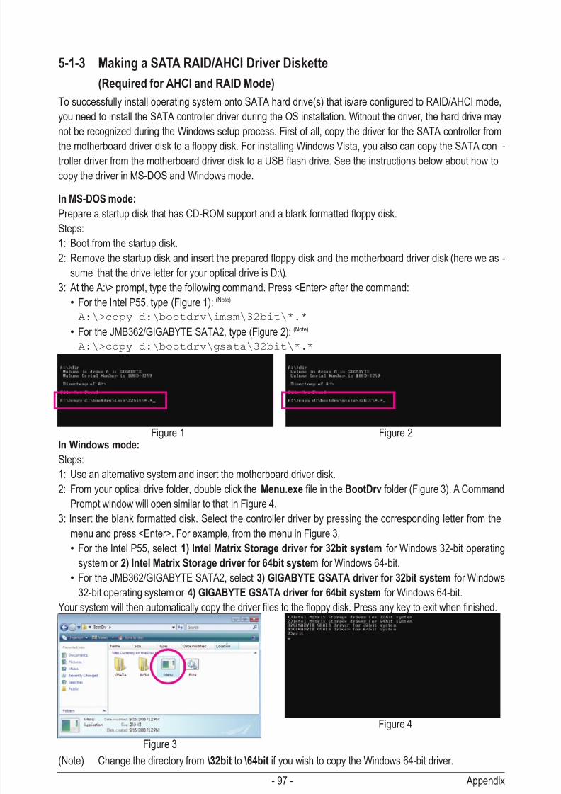
7/29/2019 GA-P55-UD3 Manual
http://slidepdf.com/reader/full/ga-p55-ud3-manual 97/128
- 97 - Appendix
5-1-3 Making a SATA RAID/AHCI Driver Diskette
(Required for AHCI and RAID Mode)
TosuccessfullyinstalloperatingsystemontoSATAharddrive(s)thatis/areconguredtoRAID/AHCImode,
you need to install the SATA controller driver during the OS installation. Without the driver, the hard drive may
not be recognized during the Windows setup process. First of all, copy the driver for the SATA controller from
themotherboarddriverdisktoaoppydisk.ForinstallingWindowsVista,youalsocancopytheSATAcon -
trollerdriverfromthemotherboarddriverdisktoaUSBashdrive.Seetheinstructionsbelowabouthowto
copy the driver in MS-DOS and Windows mode.
In MS-DOS mode:
PrepareastartupdiskthathasCD-ROMsupportandablankformattedoppydisk.
Steps:
1: Boot from the startup disk.
2: Removethestartupdiskandinsertthepreparedoppydiskandthemotherboarddriverdisk(hereweas-
sume that the drive letter for your optical drive is D:\).3: At the A:\> prompt, type the following command. Press <Enter> after the command:
• For the Intel P55, type (Figure 1): (Note)
A:\>copy d:\bootdrv\imsm\32bit\*.*
• For the JMB362/GIGABYTE SATA2, type (Figure 2): (Note)
A:\>copy d:\bootdrv\gsata\32bit\*.*
Figure 1 Figure 2
Figure 4
Figure 3
In Windows mode:
Steps:
1: Use an alternative system and insert the motherboard driver disk.
2: From your optical drive folder, double click the Menu.exeleintheBootDrv folder (Figure 3). A Command
Prompt window will open similar to that in Figure 4.
3: Insert the blank formatted disk. Select the controller driver by pressing the corresponding letter from the
menu and press <Enter>. For example, from the menu in Figure 3,
• For the Intel P55, select 1) Intel Matrix Storage driver for 32bit system for Windows 32-bit operating
system or 2) Intel Matrix Storage driver for 64bit system for Windows 64-bit.
• For the JMB362/GIGABYTE SATA2, select 3) GIGABYTE GSATA driver for 32bit system for Windows
32-bit operating system or 4) GIGABYTE GSATA driver for 64bit system for Windows 64-bit.
Yoursystemwillthenautomaticallycopythedriverlestotheoppydisk.Pressanykeytoexitwhennished.
(Note) Change the directory from \32bit to \64bit if you wish to copy the Windows 64-bit driver.

7/29/2019 GA-P55-UD3 Manual
http://slidepdf.com/reader/full/ga-p55-ud3-manual 98/128
Appendix - 98 -
5-1-4 Installing the SATA RAID/AHCI Driver and Operating System
With the SATA RAID/AHCI driver diskette and correct BIOS settings, you are ready to install Windows Vista/
XP onto your hard drive(s). The followings are examples of Windows XP and Vista installation.
A. Installing Windows XP
Step 1:
Restart your system to boot from the Windows XP setup disk and press <F6> as soon as you see the mes-
sage "Press F6 if you need to install a 3rd party SCSI or RAID driver" (Figure 1). A screen will then appear
asking you to specify additional device.
Step 2:
For the Intel P55:
InserttheoppydiskcontainingtheSATARAID/AHCIdriverandpress<S>.Thenacontrollermenusimilarto
Figure 2 below will appear. Select Intel(R) ICH8R/ICH9R/ICH10R/DO/PCH SATA RAID Controller and press
<Enter>.
Windows Setup
Press F6 if you need to install a third party SCSI or RAID driver.
Windows Setup
YouhavechosentocongureaSCSIAdapterforusewithWindows,using a device support disk provided by an adapter manufacturer.
Select the SCSI Adapter you want from the following list, or press ESC
to return to the previous screen.
ENTER=Select F3=Exit
Figure 1
Figure 2
Intel(R) ICH7R/DH SATA RAID Controller
Intel(R) ICH7MDH SATA RAID Controller
Intel(R) ICH8R/ICH9R/ICH10R/DO/PCH SATA RAID Controller
Intel(R) ICH8M-E/ICH9M-E/PCHM SATA RAID Controller

7/29/2019 GA-P55-UD3 Manual
http://slidepdf.com/reader/full/ga-p55-ud3-manual 99/128
- 99 - Appendix
For the JMB362/GIGABYTE SATA2:
InserttheoppydiskcontainingtheSATARAID/AHCIdriverandpress<S>.Thenacontrollermenusimilar
to Figure 3 below will appear. Select (Windows XP/2003) RAID/AHCI Driver for GIGABYTE GBB36X Con-
troller and press <Enter>.
Step 3:
On the next screen, press <Enter> to continue the driver installation. After the driver installation, you can pro-
ceed with the Windows XP installation.
Windows Setup
YouhavechosentocongureaSCSIAdapterforusewithWindows,
using a device support disk provided by an adapter manufacturer.
Select the SCSI Adapter you want from the following list, or press ESC
to return to the previous screen.
ENTER=Select F3=Exit
Figure 3
(Windows XP/2003) RAID/AHCI Driver for GIGABYTE GBB36X Controller
(Windows 2000) RAID Driver for GIGABYTE GBB363 Controller
(Windows 2000) AHCI Driver for GIGABYTE GBB363 Controller
(Windows 2000) RAID Driver for GIGABYTE GBB360 Controller

7/29/2019 GA-P55-UD3 Manual
http://slidepdf.com/reader/full/ga-p55-ud3-manual 100/128
Appendix - 100 -
B. Installing Windows Vista
(The procedure below assumes that only one RAID array exists in your system.)
For the Intel P55:
Step 1:
Restart your system to boot from the Windows Vista setup disk and perform standard OS installation steps.When a screen similar to that below appears, select Load Driver (Figure 4).
Step 2:
Insertthemotherboarddriverdisk(MethodA)ortheoppydisk/USBashdrivethatcontainsthedriver(Method
B), then specify the location of the driver (Figure 5). Note: For users using a SATA optical drive, be sure to
copythedriverlesfromthemotherboarddriverdisktoaUSBashdrivebeforeinstallingWindowsVista(go
to the BootDrv folder and save the whole iMSMfoldertotheUSBashdrive).ThenuseMethodBtoload
the driver.
Method A:
Insert the motherboard driver disk into your system and browse to the following directory:
\BootDrv\iMSM\32Bit
For Windows Vista 64-bit, browse to the 64Bit folder.
Method B:
InserttheUSBashdrivecontainingthedriverlesandbrowseto \iMSM\32Bit (for Windows Vista 32-bit) or
\iMSM\64Bit (for Windows Vista 64-bit).
Figure 4
Figure 5

7/29/2019 GA-P55-UD3 Manual
http://slidepdf.com/reader/full/ga-p55-ud3-manual 101/128
- 101 - Appendix
Step 3:
When a screen as shown in Figure 6 appears, select Intel(R) ICH8R/ICH9R/ICH10R/DO/PCH SATA RAID
Controller and click Next.
Step 4:
After the driver is loaded, select the RAID/AHCI drive(s) where you want to install the operating system andthen click Next to continue the OS installation (Figure 7).
Figure 6
Figure 7

7/29/2019 GA-P55-UD3 Manual
http://slidepdf.com/reader/full/ga-p55-ud3-manual 102/128
Appendix - 102 -
For the JMB362/GIGABYTE SATA2:
Step 1:
Restart your system to boot from the Windows Vista setup disk and perform standard OS installation steps.
When a screen similar to that below appears (RAID/AHCI hard drive(s) will not be detected at this stage),
select Load Driver (Figure 8).
Step 2:
Insertthemotherboarddriverdisk(MethodA)ortheoppydisk/USBashdrivethatcontainstheSATARAID/
AHCI driver (Method B), then specify the location of the driver (Figure 9). Note: For users using a SATA opti-
caldrive,besuretocopythedriverlesfromthemotherboarddriverdisktoaUSBashdrivebeforeinstall-
ing Windows Vista (go to the BootDrv folder and save the whole GSATAfoldertotheUSBashdrive).Then
use Method B to load the driver.
Method A:
Insert the motherboard driver disk into your system and browse to the following directory:
\BootDrv\GSATA\32Bit
For Windows Vista 64-bit, browse to the 64Bit folder.
Method B:
InserttheUSBashdrivecontainingthedriverlesandbrowseto \GSATA\32Bit (for Windows Vista 32-bit)
or \GSATA\64Bit (for Windows Vista 64-bit).
Figure 8
Figure 9
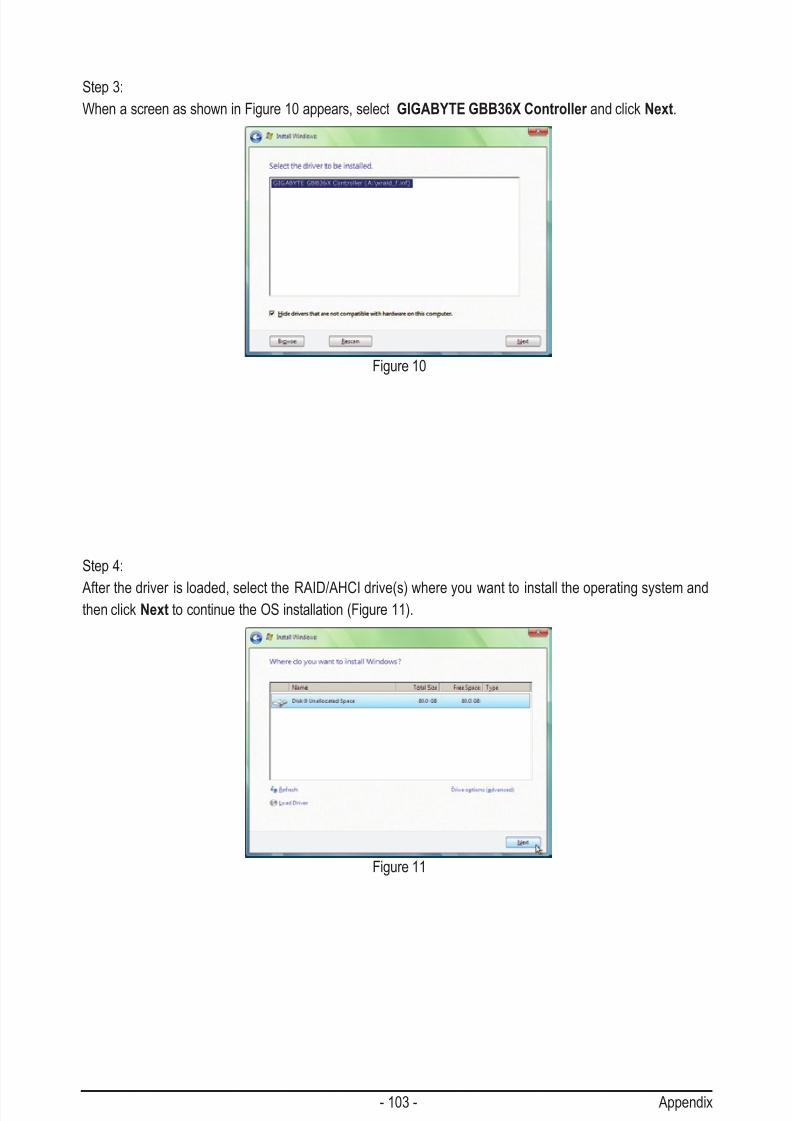
7/29/2019 GA-P55-UD3 Manual
http://slidepdf.com/reader/full/ga-p55-ud3-manual 103/128
- 103 - Appendix
Step 3:
When a screen as shown in Figure 10 appears, select GIGABYTE GBB36X Controller and click Next.
Step 4:
After the driver is loaded, select the RAID/AHCI drive(s) where you want to install the operating system andthen click Next to continue the OS installation (Figure 11).
Figure 10
Figure 11

7/29/2019 GA-P55-UD3 Manual
http://slidepdf.com/reader/full/ga-p55-ud3-manual 104/128
Appendix - 104 -
Intel(R) Matrix Storage Manager option ROM v8.9.0.1023 PCH-D wRAID5
Copyright(C) 2003-09 Intel Corporation. All Rights Reserved.
3. Reset Disks to Non-RAID
4. Exit
RAID Volumes :
Nonedened.
Physical Disks :
Port Drive Model Serial # Size Type/Status(Vol ID)
0 ST3120026AS 3JT354CP 111.7GB Member Disk (0)
1 WDC WD800JD-22LS WD-WMAM9W736333 111.7GB Non-RAID Disk
[hi]-Select [ESC]-Exit [ENTER]-Select Menu
[ DISK/VOLUME INFORMATION ]
[ MAIN MENU ]
1. Create RAID Volume
2. Delete RAID Volume
C. Rebuilding an Array
Rebuilding is the process of restoring data to a hard drive from other drives in the array. Rebuilding applies
only to fault-tolerant arrays such as RAID 1, RAID 5 or RAID 10 arrays. The procedures below assume a new
drive is added to replace a failed drive to rebuild a RAID 1 array. (Note: The new drive must have equal or
greater capacity than the old one.)
For the Intel P55:
Turn off your computer and replace the failed hard drive with a new one. Restart your computer.
• Enabling Automatic Rebuild
Step 1:
Whenthemessage"Press<Ctrl-I>toenterCongurationUtility"appears,press<Ctrl>+<I>toenterthe
RAIDCongurationUtility.ThefollowingscreenappearsafteryouentertheRAIDCongurationUtility.
Step 2:
Select the new hard drive to add into the array to be rebuilt and press <Enter>. The following screen appears,
indicating that an automatic rebuild will be performed after you enter the operating system (look for the Intel
Storage Console icon inthenoticationarea,whichwillshowthataRAIDvolumeisbeingrebuilt).Ifyou
do not enable automatic rebuild on this stage, you have to manually rebuild the array in the operating system
(see the next page for more details).
[ DEGRADED VOLUME DETECTED ]
[hi]-Previous/Next [ENTER]-Select [ESC]-Exit
"Degraded volume and disk available for rebuilding detected. Selecting
a disk initiates a rebuild. Rebuild completes in the operating system.
Select the port of the destination disk for rebuilding (ESC to exit):
Port Drive Model Serial # Size
1 WDC WD800JD-22LS WD-WMAM9W736333 111.7GB
Intel(R) Matrix Storage Manager option ROM v8.9.0.1023 PCH-D wRAID5
Copyright(C) 2003-09 Intel Corporation. All Rights Reserved.
RAID Volumes :
ID Name Level Strip Size Status Bootable
0 Volume0 RAID1(Mirror) N/A 111.7GB Rebuild Yes
Physical Disks :
Port Drive Model Serial # Size Type/Status(Vol ID)0 ST3120026AS 3JT354CP 111.7GB Member Disk (0)
1 WDC WD800JD-22LS WD-WMAM9W736333 111.7GB Member Disk (0)
[hi]-Select [ESC]-Exit [ENTER]-Select Menu
[ DISK/VOLUME INFORMATION ]
Volumes with "Rebuild" status will be rebuilt within the operating system.
3. Reset Disks to Non-RAID
4. Recovery Volume Options
[ MAIN MENU ]
1. Create RAID Volume
2. Delete RAID Volume5. Exit

7/29/2019 GA-P55-UD3 Manual
http://slidepdf.com/reader/full/ga-p55-ud3-manual 105/128
- 105 - Appendix
• Performing the Rebuild in the Operating System
While in the operating system, make sure the chipset driver has been installed from the motherboard driver
disk. Then launch the Intel Matrix Storage Console from All Programs in the Start menu.
Step 1:
On the View menu of the Intel Matrix Storage
Console, select Advanced Mode for a moredetailed view of the storage device information.
Step 3:
Click Next when the Rebuild RAID Volume
Wizard appears. Follow the on-screen instruc-
tions to proceed.
Step 5:
When the message "The rebuild was completed
successfully," appears, click OK to complete.
Step 2:
The new hard drive appears under Non-RAID
Hard Drive. Right-click on the new hard driveand select Rebuild to this Hard Drive.
Step 4:
To check the rebuild status during the rebuild
process, right-click on the rebuild volume and
select Show Rebuild Progress.
Step 6:
After the RAID 1 volume rebuilding, click the
volume and its status in the information pane will
display as Normal.

7/29/2019 GA-P55-UD3 Manual
http://slidepdf.com/reader/full/ga-p55-ud3-manual 106/128
Appendix - 106 -
• Restoring the Master Drive to a Previous State (for Recovery Volume only)
When two hard drives are set to Recovery Volume in Update on Request mode, you can restore the master
drive data to the last backup state when needed. For example, in case the master drive detects a virus, you
can restore the recovery drive data to the master drive.
Step 1:
Select 4. Recovery Volume Options in the MAIN MENUoftheP55RAIDCongurationUtility.Onthe RE-
COVERY OPTIONS menu, select Enable Only Recovery Disk to show the recovery drive in the operating
system.Followtheon-screeninstructionstocompleteandexittheRAIDCongurationUtility.
Step 2:
Enter the operating system, launch the Intel Matrix Storage Console from All Programs in the Start menu,
and select Advanced Mode. Right-click on the recovery volume and select Recover Data to Master .
Step 3:
To check the recovery status, right-click on the recovery volume and select Show Recovery Progress. When
a dialog box indicating that the recovery is completed appears, click OK to complete.
Intel(R) Matrix Storage Manager option ROM v8.9.0.1023 PCH-D wRAID5
Copyright(C) 2003-09 Intel Corporation. All Rights Reserved.
Choose the RAID level:
RAID0: Stripes data (performance).
RAID1: Mirrors data (redundancy).
Recovery: Copies data between a master and a recovery disk.
RAID10: Mirrors data and stripes the mirror.
RAID5: Stripes data and parity.
[hi]-select [ESC]-Previous Menu [ENTER]-Select
[ HELP ]
[ RECOVERY VOLUME OPTIONS ]
1. Enable Only Recovery Disk
2. Enable Only Master Disk
[ SELECT RECOVERY VOLUME ]
[hi]-Up/Down [SPACE]-Selects [ENTER]-Done
Name Level Capacity Status Bootable
Volume0 Recovery(OnReq) 111.7GB NeedsUpdate Yes
Select a Recovery volume to do the operation.

7/29/2019 GA-P55-UD3 Manual
http://slidepdf.com/reader/full/ga-p55-ud3-manual 107/128
- 107 - Appendix
For the JMB362/GIGABYTE SATA2:
Turn off your computer and replace the failed hard drive with a new one. Use either the RAID setup utility or
the GIGABYTE RAID CONFIGURER utility in the operating system to perform the rebuild.
• Rebuilding with the RAID setup utility
Step 1:
When the message "Press <Ctrl-G> to enter RAID Setup Utility" appears, press <Ctrl> + <G> to enter the util-
ity. In the Main Menu block, select Rebuild Mirror Drive and press <Enter>. The selection bar will move to
the degraded array. Press <Enter> again.
Step 2:
The selection bar will then move to new hard drive in the Hard Disk Drive List block. Press <Enter> to start
the RAID rebuilding process. The rebuilding progress is displayed at the bottom of the screen. When done,
the status of the array will display as Normal.
Model Name RAID Level Capacity Status Members(HDDx)
RDD0: GRAID 1-Mirror 120 GB Degraded 0?
[fgTAB]-Switch Window [hi]-Select RAID [ENTER]-Action [ESC]-Exit
[ RAID Disk Drive List ]
[ Main Menu ] [ Hard Disk Drive List ]
Gigabyte Technology Corp. RAID Setup Utility v1.07.06
Create RAID Disk DriveDelete RAID Disk DriveRevert HDD to Non-RAIDSolveMirrorConictRebuild Mirror DriveSave And Exit Setup
Exit Without Saving
Model Name Capacity Type/StatusHDD0: ST3120026AS 120 GB RAID InsideHDD1: ST3120026AS 120 GB Non-RAID
Model Name RAID Level Capacity Status Members(HDDx)
RDD0: GRAID 1-Mirror 120 GB Degraded 0?
Rebuilding....35%, please wait....
[ RAID Disk Drive List ]
[ Main Menu ] [ Hard Disk Drive List ]
Gigabyte Technology Corp. RAID Setup Utility v1.07.06
Create RAID Disk DriveDelete RAID Disk Drive
Revert HDD to Non-RAIDSolveMirrorConictRebuild Mirror DriveSave And Exit SetupExit Without Saving
Model Name Capacity Type/StatusHDD0: ST3120026AS 120 GB RAID Inside
HDD1: ST3120026AS 120 GB Non-RAID

7/29/2019 GA-P55-UD3 Manual
http://slidepdf.com/reader/full/ga-p55-ud3-manual 108/128
Appendix - 108 -
• Rebuilding in the operating system
Make sure the JMB362/GIGABYTE SATA2 SATA controller driver has been installed from the motherboard
driver disk. Launch the GIGABYTE RAID CONFIGURER from All Programs in the Start menu.
Step 1:In the GIGABYTE RAID CONFIGURER screen,
right-click on the array to be rebuilt in the RAID
LIST block. Select Rebuild Raid. (Or click the
Rebuild icon in the tool bar.)
Step 3:
Select a drive to rebuild the array and click Next.
Step 2:
When the Rebuilding RAID Wizard appears,
click Next.
Step 4:
Click Finish to start the RAID rebuilding process.
Step 6:
Whennished,restartyoursystem.
Step 5:The rebuilding progress is displayed at the
bottom of the screen.
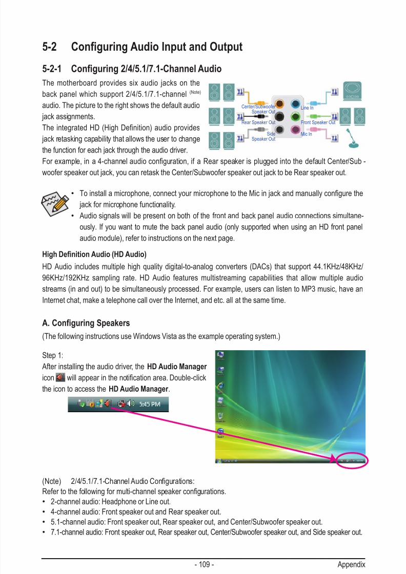
7/29/2019 GA-P55-UD3 Manual
http://slidepdf.com/reader/full/ga-p55-ud3-manual 109/128
- 109 - Appendix
5-2-1 Conguring 2/4/5.1/7.1-Channel Audio
The motherboard provides six audio jacks on the
back panel which support 2/4/5.1/7.1-channel (Note)
audio. The picture to the right shows the default audio
jack assignments.
The integrated HD (High Definition) audio provides
jack retasking capability that allows the user to change
the function for each jack through the audio driver.
Forexample,ina4-channelaudioconguration,ifaRearspeakerispluggedintothedefaultCenter/Sub-
woofer speaker out jack, you can retask the Center/Subwoofer speaker out jack to be Rear speaker out.
5-2 Conguring Audio Input and Output
High Denition Audio (HD Audio)
HD Audio includes multiple high quality digital-to-analog converters (DACs) that support 44.1KHz/48KHz/
96KHz/192KHz sampling rate. HD Audio features multistreaming capabilities that allow multiple audio
streams (in and out) to be simultaneously processed. For example, users can listen to MP3 music, have an
Internet chat, make a telephone call over the Internet, and etc. all at the same time.
A. Conguring Speakers
(The following instructions use Windows Vista as the example operating system.)
• Toinstallamicrophone,connectyourmicrophonetotheMicinjackandmanuallycongurethe
jack for microphone functionality.
• Audio signals will be present on both of the front and back panel audio connections simultane-
ously. If you want to mute the back panel audio (only supported when using an HD front panel
audio module), refer to instructions on the next page.
Step 1:
After installing the audio driver, the HD Audio Manager
icon willappearinthenoticationarea.Double-click
the icon to access the HD Audio Manager .
(Note) 2/4/5.1/7.1-ChannelAudioCongurations:
Refertothefollowingformulti-channelspeakercongurations.
• 2-channel audio: Headphone or Line out.• 4-channel audio: Front speaker out and Rear speaker out.
• 5.1-channel audio: Front speaker out, Rear speaker out, and Center/Subwoofer speaker out.
• 7.1-channel audio: Front speaker out, Rear speaker out, Center/Subwoofer speaker out, and Side speaker out.
Center/Subwoofer Speaker Out
Line In
Rear Speaker Out Front Speaker Out
Mic InSideSpeaker Out
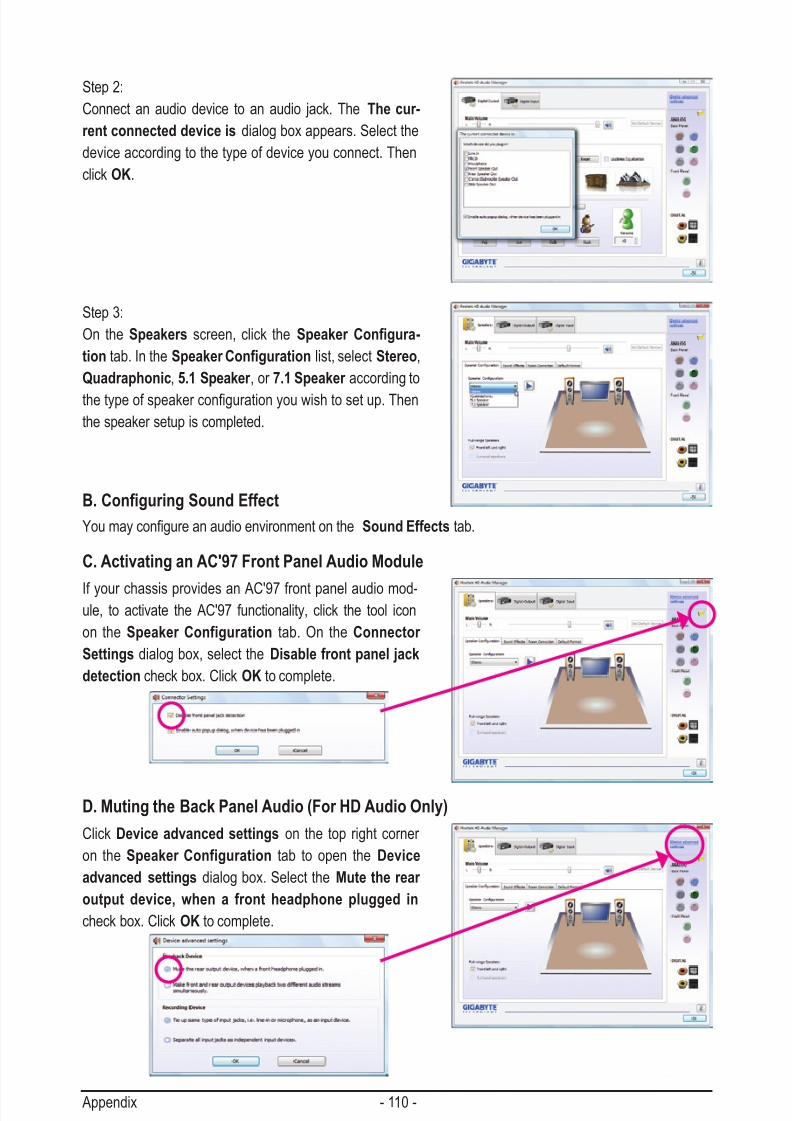
7/29/2019 GA-P55-UD3 Manual
http://slidepdf.com/reader/full/ga-p55-ud3-manual 110/128
Appendix - 110 -
Step 2:
Connect an audio device to an audio jack. The The cur-
rent connected device is dialog box appears. Select the
device according to the type of device you connect. Then
click OK.
Step 3:
On the Speakers screen, click the Speaker Congura-
tion tab. In the Speaker Conguration list, select Stereo,
Quadraphonic, 5.1 Speaker , or 7.1 Speaker according to
thetypeofspeakercongurationyouwishtosetup.Then
the speaker setup is completed.
If your chassis provides an AC'97 front panel audio mod-ule, to activate the AC'97 functionality, click the tool icon
on the Speaker Configuration tab. On the Connector
Settings dialog box, select the Disable front panel jack
detection check box. Click OK to complete.
Click Device advanced settings on the top right corner
on the Speaker Configuration tab to open the Device
advanced settings dialog box. Select the Mute the rear
output device, when a front headphone plugged in
check box. Click OK to complete.
B. Conguring Sound Effect
Youmaycongureanaudioenvironmentonthe Sound Effects tab.
C. Activating an AC'97 Front Panel Audio Module
D. Muting the Back Panel Audio (For HD Audio Only)

7/29/2019 GA-P55-UD3 Manual
http://slidepdf.com/reader/full/ga-p55-ud3-manual 111/128
- 111 - Appendix
5-2-2 Conguring S/PDIF In/Out
A. S/PDIF In
The S/PDIF In cable (optional) allows you to input digital audio signals to the computer for audio processing.
1. Installing the S/PDIF In Cable:
2. Conguring S/PDIF In:
On the Digital Input screen, click the Default Format tab to select the default format. Click OK to complete.
(Note) The actual locations of the S/PDIF In and S/PDIF Out connectors may differ by model.
S/PDIF In Cable
OpticalS/PDIF In
CoaxialS/PDIF In
Step 1:
First, attach the connector at the end of the cable
to the SPDIF_I header on your motherboard.
Step 2:
Secure the metal bracket to the chassis back
panel with a screw.
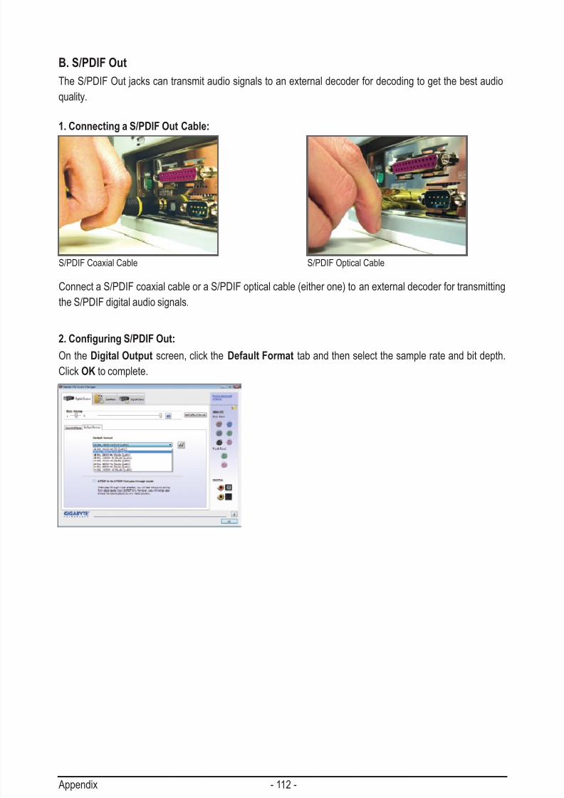
7/29/2019 GA-P55-UD3 Manual
http://slidepdf.com/reader/full/ga-p55-ud3-manual 112/128
Appendix - 112 -
B. S/PDIF Out
The S/PDIF Out jacks can transmit audio signals to an external decoder for decoding to get the best audio
quality.
1. Connecting a S/PDIF Out Cable:
2. Conguring S/PDIF Out:
On the Digital Output screen, click the Default Format tab and then select the sample rate and bit depth.
Click OK to complete.
S/PDIF Coaxial Cable
Connect a S/PDIF coaxial cable or a S/PDIF optical cable (either one) to an external decoder for transmitting
the S/PDIF digital audio signals.
S/PDIF Optical Cable
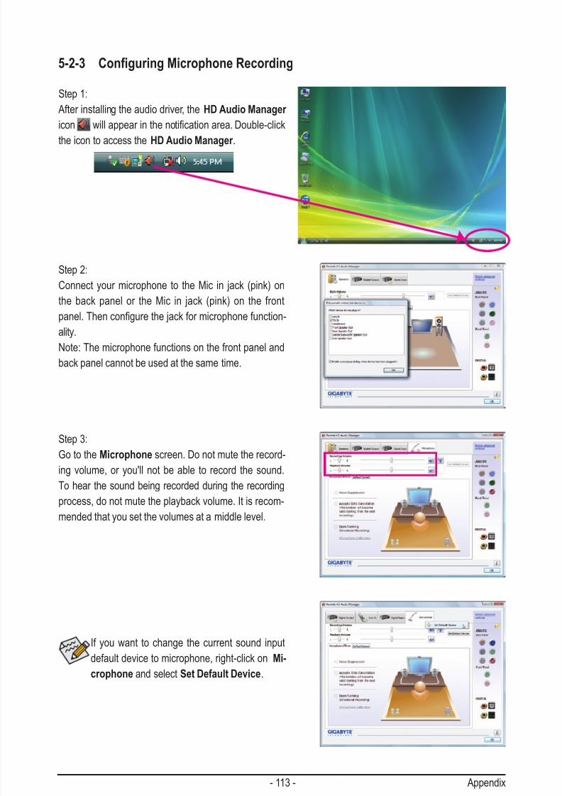
7/29/2019 GA-P55-UD3 Manual
http://slidepdf.com/reader/full/ga-p55-ud3-manual 113/128
- 113 - Appendix
5-2-3 Conguring Microphone Recording
Step 1:
After installing the audio driver, the HD Audio Manager
icon willappearinthenoticationarea.Double-click
the icon to access the HD Audio Manager .
Step 2:
Connect your microphone to the Mic in jack (pink) on
the back panel or the Mic in jack (pink) on the front
panel.Thencongurethejackformicrophonefunction-
ality.
Note: The microphone functions on the front panel and
back panel cannot be used at the same time.
Step 3:
Go to the Microphone screen. Do not mute the record-
ing volume, or you'll not be able to record the sound.
To hear the sound being recorded during the recording
process, do not mute the playback volume. It is recom-
mended that you set the volumes at a middle level.
If you want to change the current sound input
default device to microphone, right-click on Mi-
crophone and select Set Default Device.

7/29/2019 GA-P55-UD3 Manual
http://slidepdf.com/reader/full/ga-p55-ud3-manual 114/128
Appendix - 114 -
Step 4:
To raise the recording and playback volume for the
microphone, click the Microphone Boost icon on
the right of the Recording Volume slider and set the
Microphone Boost level.
Step 5:
After completing the settings above, click Start, point
to All Programs, point to Accessories, and then click
Sound Recorder to begin the sound recording.
Step 1:
Locate the Volume icon inthenoticationareaand
right-click on this icon. Select Recording Devices.
Step 2:
On the Recording tab, right-click on an empty space
and select Show Disabled Devices.
* Enabling Stereo Mix
If the HD Audio Manager does not display the recording device you wish to use, refer to the steps below. The
following steps explain how to enable Stereo Mix (which may be needed when you want to record sound from
your computer).
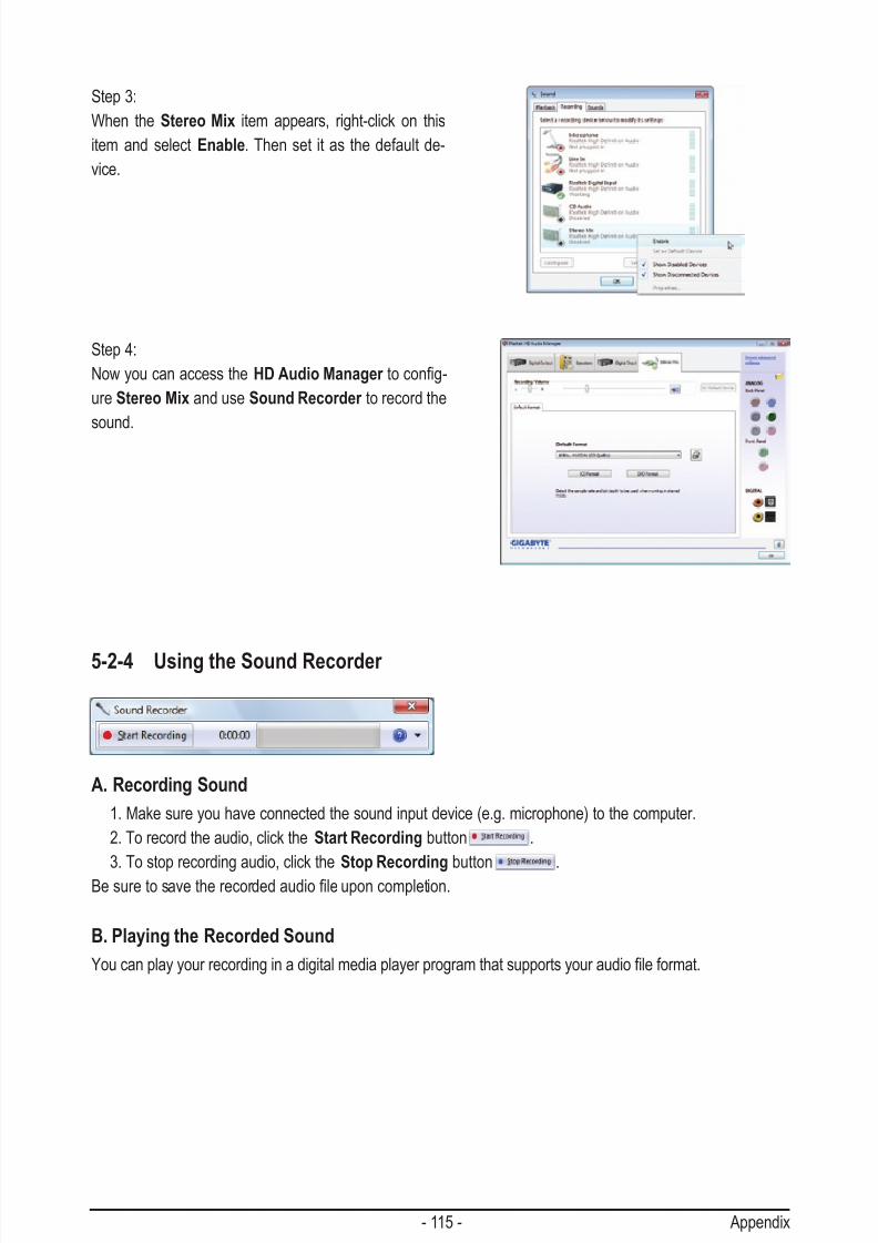
7/29/2019 GA-P55-UD3 Manual
http://slidepdf.com/reader/full/ga-p55-ud3-manual 115/128
- 115 - Appendix
Step 3:
When the Stereo Mix item appears, right-click on this
item and select Enable. Then set it as the default de-
vice.
Step 4:
Now you can access the HD Audio Manager tocong-
ure Stereo Mix and use Sound Recorder to record the
sound.
5-2-4 Using the Sound Recorder
A. Recording Sound
1. Make sure you have connected the sound input device (e.g. microphone) to the computer.
2. To record the audio, click the Start Recording button .
3. To stop recording audio, click the Stop Recording button .
Besuretosavetherecordedaudioleuponcompletion.
B. Playing the Recorded Sound
Youcanplayyourrecordinginadigitalmediaplayerprogramthatsupportsyouraudioleformat.

7/29/2019 GA-P55-UD3 Manual
http://slidepdf.com/reader/full/ga-p55-ud3-manual 116/128
Appendix - 116 -
5-3 Troubleshooting
5-3-1 Frequently Asked Questions
To read more FAQs for your motherboard, please go to the Support&Downloads\Motherboard\FAQ page on
GIGABYTE's website.
Q: In the BIOS Setup program, why are some BIOS options missing?
A: Some advanced options are hidden in the BIOS Setup program. Press <Delete> to enter BIOS Setup during the POST. In
the Main Menu, press <Ctrl>+<F1> to show the advanced options.
Q: Why is the light of my keyboard/optical mouse still on after the computer shuts down?
A: Some motherboards provide a small amount of standby power after the computer shuts down and that's why the light is
still on.
Q: How do I clear the CMOS values?
A: For motherboards that have a CMOS_SW button, press this button to clear the CMOS values (before doing this, please
turn off the computer and unplug the power cord). For motherboards that have a clearing CMOS jumper, refer to the
instructions on the CLR_CMOS jumper in Chapter 1 to short the jumper to clear the CMOS values. If your board doesn't
have this jumper, refer to the instructions on the motherboard battery in Chapter 1. You can temporarily remove the bat-
tery from the battery holder to stop supplying power to the CMOS, which will clear the CMOS values after about one
minute.
Q: Why do I still get a weak sound even though I have turned my speaker to the maximum volume?
A: Makesureyourspeakerisequippedwithaninternalamplier.Ifnot,tryaspeakerwithpower/amplier.
Q: Why cannot I install the onboard HD audio driver successfully? (For Windows XP only)
A: Step 1: First, make sure Service Pack 1 or Service Pack 2 has been installed (check in My Computer > Properties > Gen-
eral > System). If not, please update it from Microsoft's website. Then make sure the Microsoft UAA Bus Driver for
HighDenitionAudiohasbeeninstalledsuccessfully(checkinMyComputer>Properties>Hardware>Device
Manager > System Devices).
Step 2: Check if Audio Device on High Denition Audio Bus or Unknown device is present in Device Manager or
Sound, video, and game controllers. If yes, please disable this device. (If not, skip this step.)
Step 3: Then go back to My Computer > Properties > Hardware > Device Manager > System devices and right-click on
Microsoft UAA Bus Driver for High Denition Audio and select Disable and Uninstall.
Step 4: In Device Manager , right-click on the computer name and select Scan for hardware changes. When the Add
New Hardware Wizard appears, click Cancel. Then install the onboard HD audio driver from the motherboard
driver disk or download the audio driver from GIGABYTE's website to install.
For more details, go to the Support&Downloads\Motherboards\FAQ page on our website and search for "onboard HD
audio driver."
Q: What do the beeps emitted during the POST mean?
A: The following Award BIOS beep code descriptions may help you identify possible computer problems.
(For reference only.)1 short: System boots successfully
2 short: CMOS setting error
1 long, 1 short: Memory or motherboard error
1 long, 2 short: Monitor or graphics card error
1 long, 3 short: Keyboard error
1 long, 9 short: BIOS ROM error
Continuous long beeps: Graphics card not inserted properly
Continuous short beeps: Power error

7/29/2019 GA-P55-UD3 Manual
http://slidepdf.com/reader/full/ga-p55-ud3-manual 117/128
- 117 - Appendix
5-3-2 Troubleshooting Procedure
If you encounter any troubles during system startup, follow the troubleshooting procedure below to solve the
problem.
START
A
Turn off the power. Remove all peripherals, connecting cables, and
power cord etc.
Isolate the short circuit.
Secure the CPU cooler
on the CPU. Connect the
CPU cooler power cable
to the motherboard.
Correctly insert the
memory into the memory
socket.
(Continued...)
Yes
Theproblemisveriedandsolved.
Theproblemisveriedandsolved.
Theproblemisveriedandsolved.
No
No
No
Yes
Yes
Insert the graphics card. Connect the ATX main power cable and the
12V power cable. Turn on the power to start the computer.
Make sure the motherboard does not short-circuit with the chassis or
other metal objects.
Check if the CPU cooler is attached to the CPU securely. Is the pow-er connector of the CPU cooler connected to the CPU_FAN header properly?
Check if the memory is installed properly on the memory slot.
Make sure the graphics card is securely seated in theexpansionslotandpowerconnectorsarermlyattached.
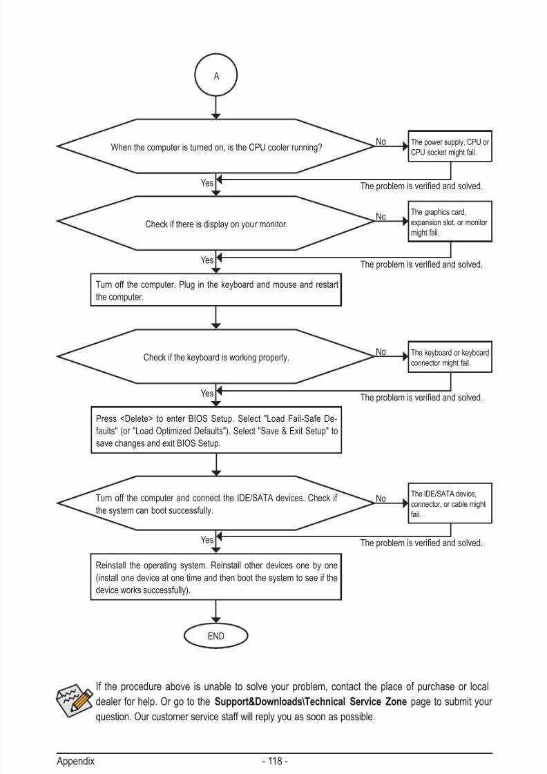
7/29/2019 GA-P55-UD3 Manual
http://slidepdf.com/reader/full/ga-p55-ud3-manual 118/128

7/29/2019 GA-P55-UD3 Manual
http://slidepdf.com/reader/full/ga-p55-ud3-manual 119/128
- 119 - Appendix
5-4 Regulatory Statements
Regulatory Notices
This document must not be copied without our written permission, and the contents there of must not be
imparted to a third party nor be used for any unauthorized purpose. Contravention will be prosecuted. Webelieve that the information contained herein was accurate in all respects at the time of printing. GIGABYTE
cannot, however, assume any responsibility for errors or omissions in this text. Also note that the informa-
tion in this document is subject to change without notice and should not be construed as a commitment by
GIGABYTE.
Our Commitment to Preserving the Environment
Inadditiontohigh-efciencyperformance,allGIGABYTEmotherboardsfulllEuropeanUnionregulations
for RoHS (Restriction of Certain Hazardous Substances in Electrical and Electronic Equipment) and WEEE
(Waste Electrical and Electronic Equipment) environmental directives, as well as most major worldwide safety
requirements. To prevent releases of harmful substances into the environment and to maximize the use of our natural resources, GIGABYTE provides the following information on how you can responsibly recycle or
reuse most of the materials in your "end of life" product.
Restriction of Hazardous Substances (RoHS) Directive Statement
GIGABYTE products have not intended to add and safe from hazardous substances (Cd, Pb, Hg, Cr+6,
PBDE and PBB). The parts and components have been carefully selected to meet RoHS requirement. More-
over, we at GIGABYTE are continuing our efforts to develop products that do not use internationally banned
toxic chemicals.
Waste Electrical & Electronic Equipment (WEEE) Directive Statement
GIGABYTEwillfulllthenationallawsasinterpretedfromthe2002/96/ECWEEE(WasteElectricalandElec-
tronicEquipment)directive.TheWEEEDirectivespeciesthetreatment,collection,recyclinganddisposalof
electric and electronic devices and their components. Under the Directive, used equipment must be marked,
collected separately, and disposed of properly.
WEEE Symbol Statement
The symbol shown below is on the product or on its packaging, which indicates that this product
must not be disposed of with other waste. Instead, the device should be taken to the waste
collection centers for activation of the treatment, collection, recycling and disposal procedure.
The separate collection and recycling of your waste equipment at the time of disposal will help to
conserve natural resources and ensure that it is recycled in a manner that protects human health
and the environment. For more information about where you can drop off your waste equipment for recycling,
pleasecontactyourlocalgovernmentofce,yourhouseholdwastedisposalserviceorwhereyoupurchased
the product for details of environmentally safe recycling.
When your electrical or electronic equipment is no longer useful to you, "take it back" to your local or
regional waste collection administration for recycling.
If you need further assistance in recycling, reusing in your "end of life" product, you may contact us at the
Customer Care number listed in your product's user's manual and we will be glad to help you with your effort.

7/29/2019 GA-P55-UD3 Manual
http://slidepdf.com/reader/full/ga-p55-ud3-manual 120/128
Appendix - 120 -
Finally, we suggest that you practice other environmentally friendly actions by understanding and using the
energy-saving features of this product (where applicable), recycling the inner and outer packaging (including
shipping containers) this product was delivered in, and by disposing of or recycling used batteries properly.
With your help, we can reduce the amount of natural resources needed to produce electrical and electronic
equipment,minimizetheuseoflandllsforthedisposalof"endoflife"products,andgenerallyimproveour
quality of life by ensuring that potentially hazardous substances are not released into the environment and
are disposed of properly.
China Restriction of Hazardous Substances Table
The following table is supplied in compliance with China's Restriction of Hazardous Substances (China
RoHS) requirements:

7/29/2019 GA-P55-UD3 Manual
http://slidepdf.com/reader/full/ga-p55-ud3-manual 121/128
- 121 - Appendix

7/29/2019 GA-P55-UD3 Manual
http://slidepdf.com/reader/full/ga-p55-ud3-manual 122/128
Appendix - 122 -

7/29/2019 GA-P55-UD3 Manual
http://slidepdf.com/reader/full/ga-p55-ud3-manual 123/128
- 123 - Appendix

7/29/2019 GA-P55-UD3 Manual
http://slidepdf.com/reader/full/ga-p55-ud3-manual 124/128
Appendix - 124 -

7/29/2019 GA-P55-UD3 Manual
http://slidepdf.com/reader/full/ga-p55-ud3-manual 125/128
- 125 - Appendix

7/29/2019 GA-P55-UD3 Manual
http://slidepdf.com/reader/full/ga-p55-ud3-manual 126/128
Appendix - 126 -
7/29/2019 GA-P55-UD3 Manual
http://slidepdf.com/reader/full/ga-p55-ud3-manual 127/128
- 127 - Appendix
Contact Us
• GIGA-BYTE TECHNOLOGY CO., LTD.
Address: No.6, Bau Chiang Road, Hsin-Tien,Taipei 231, Taiwan
TEL: +886-2-8912-4000
FAX: +886-2-8912-4003
Tech. and Non-Tech. Support (Sales/Marketing) :
http://ggts.gigabyte.com.tw
WEB address (English): http://www.gigabyte.com.tw
WEB address (Chinese): http://www.gigabyte.tw
• G.B.T. INC. - U.S.A.
TEL: +1-626-854-9338
FAX: +1-626-854-9339
Tech. Support:
http://rma.gigabyte-usa.com
Web address: http://www.gigabyte.us
• G.B.T. INC (USA) - Mexico
Tel: +1-626-854-9338 x 215 (Soporte de habla hispano)
FAX: +1-626-854-9339
Correo: [email protected]
Tech. Support:
http://rma.gigabyte-usa.com
Web address: http://latam.giga-byte.com
• Giga-Byte SINGAPORE PTE. LTD. - Singapore
WEB address : http://www.gigabyte.sg
• Thailand
WEB address : http://th.giga-byte.com
• Vietnam
WEB address : http://www.gigabyte.vn
• NINGBO G.B.T. TECH. TRADING CO., LTD. - China
WEB address : http://www.gigabyte.cnShanghai
TEL: +86-21-63410999
FAX: +86-21-63410100
Beijing
TEL: +86-10-62102838
FAX: +86-10-62102848
Wuhan
TEL: +86-27-87851312
FAX: +86-27-87851330
GuangZhou
TEL: +86-20-87540700
FAX: +86-20-87544306
Chengdu
TEL: +86-28-85236930
FAX: +86-28-85256822
Xian
TEL: +86-29-85531943
FAX: +86-29-85510930
Shenyang
TEL: +86-24-83992901
FAX: +86-24-83992909
• GIGABYTE TECHNOLOGY (INDIA) LIMITED - India
WEB address : http://www.gigabyte.in
• Saudi Arabia
WEB address : http://www.gigabyte.com.sa
• Gigabyte Technology Pty. Ltd. - Australia
WEB address : http://www.gigabyte.com.au

7/29/2019 GA-P55-UD3 Manual
http://slidepdf.com/reader/full/ga-p55-ud3-manual 128/128
• G.B.T. TECHNOLOGY TRADING GMBH - Germany
WEB address : http://www.gigabyte.de• G.B.T. TECH. CO., LTD. - U.K.
WEB address : http://www.giga-byte.co.uk
• Giga-Byte Technology B.V. - The Netherlands
WEB address : http://www.giga-byte.nl
• GIGABYTE TECHNOLOGY FRANCE - France
WEB address : http://www.gigabyte.fr
• Sweden
WEB address : http://www.giga-byte.se
• Italy
WEB address : http://www.giga-byte.it
• Spain
WEB address : http://www.giga-byte.es
• Greece
WEB address : http://www.giga-byte.gr
• Czech Republic
WEB address : http://www.gigabyte.cz
• Hungary
WEB address : http://www.giga-byte.hu• Turkey
WEB address : http://www.gigabyte.com.tr
• Russia
WEB address : http://www.gigabyte.ru
• Poland
WEB address : http://www.gigabyte.pl
• Ukraine
WEB address : http://www.gigabyte.ua
• Romania
WEB address : http://www.gigabyte.com.ro
• Serbia
WEB address : http://www.gigabyte.co.yu
• Kazakhstan
WEB address : http://www.giga-byte.kz
You may go to the GIGABYTE website, select your language
in the language list on the top right corner of the website.
• GIGABYTE Global Service System
To submit a technical or non-technical (Sales/Market-