g8 - contracts for difference metering
TRANSCRIPT
G8 - Contracts for Difference Metering
EMRS Guidance
Public
Version: 7.0
Date: 1 September 2021
G8 - Contracts for Difference Metering
© Low Carbon Contracts Company 2021
Disclaimer: Please note that whilst this document has been prepared with due care by EMR Settlement Limited on behalf of the Low Carbon Contract Company, EMR Settlement Limited and Low Carbon Contract
Company do not make any representation, warranty or undertaking, express or implied, in relation to the completeness and or accuracy of information contained in this document, and accordingly neither EMR Settlement Limited or Low Carbon Contract Company shall be liable for any damages resulting from the use of this information or action taken in reliance on it.
Table of Contents
Change Amendment Record .................................................................................... 3
1. Introduction ..................................................................................................... 4
2. Purpose ........................................................................................................... 4
3. Who is this document for? .................................................................................. 4
4. Associated Documents ....................................................................................... 5
5. What is the Electrical Schematic Obligation? ......................................................... 6
6. What are the metering requirements for CfD Generators registered in the BSC? ....... 7
7. What are the metering requirements for CfD Generators registered in the BSC that
are a Dual Scheme ............................................................................................... 10
8. What are the metering requirements for CfD Generators registered in the BSC that
are Offshore Wind and building the Facility in Phases? .............................................. 11
9. What are the metering requirements for CfD Generators operating on a Private
Network? ............................................................................................................ 13
10. What are the test facility requirements? .......................................................... 20
11. What are the Meter setup requirements? ......................................................... 23
12. How do I submit my aggregation rules? .......................................................... 23
13. What if my metering arrangements change? .................................................... 24
G8 - Contracts for Difference Metering
© Low Carbon Contracts Company 2021
Version 7.0 Page 3 of 26
Change Amendment Record
Version Date Description
1.0 25 October 2015 Go Live version
2.0 15 August 2017 Document transfer to new template
3.0 11 January 2018 Updated Section 9 on the requirements for metering for
a Private Network CfD.
Moved figures from Appendix to the body of the
document.
4.0 14 June 2019 Associated documents updated to remove obsolete
document reference.
Section 6.1 and 6.2 updated to refer to back up supplies
5.0 30 December 2019 Section added on aggregation rules and metering
equipment/arrangement changes
6.0 27 January 2021 Links updated and housekeeping changes throughout
document; Added detail for clarifications in sections 6.2,
8.2 and 12.
7.0 1 September 2021 Link to BSCP514 removed and replaced with link to the
Retail Energy Code Metering Operations Schedule
G8 - Contracts for Difference Metering
© Low Carbon Contracts Company 2021
Version 7.0 Page 4 of 26
1. Introduction
To be able to participate in the Electricity Market Reform (EMR) Contracts for Difference (CfD) all
CfD Generators must have a Metering System installed that is compliant with the CfD Agreement
Terms and Conditions. This Metering System must be installed at such a point so as to exclusively
measure all imports and exports of energy to and from the Facility.
The metering requirements in the CfD agreement can vary depending on the individual configuration
of the CfD Generator. This can be as a result of the Generator type (e.g. Baseload, Intermittent, and
Dual Scheme), building the scheme in a modular way or operating on a Private Network. Each CfD
Generator will have an individual Agreement that will specify that Generator’s requirements to the
Low Carbon Contracts Company (LCCC); the CfD Counterparty.
EMR Settlements (EMRS), acting on behalf of LCCC, review evidence submitted to prove compliance
with the Operational Conditions Precedents (OCP) related to metering (i.e. OCP 2.1 (C), (D) and
(E)1). This guidance is only relevant to metering and the associated OCPs.
This guidance has been written to be generally relevant to all Investment Contracts and all CfD
allocation round contracts. The specific metering obligations of each contract can and do vary and
the reader will need to check and confirm which parts of the guidance applies to their project.
2. Purpose
The purpose of this document is to answer the following questions:
What is the Electrical Schematic Obligation?
What are the metering requirements for CfD Generators registered in the BSC?
What are the metering requirements for CfD Generators registered in the BSC that are a Dual
Scheme?
What are the metering requirements for CfD Generators registered in the BSC that are
Offshore Wind and building the Facility in phases?
What are the metering requirements for CfD Generators operating on a Private Network?
What are the test facility requirements?
What are the Meter setup requirements?
How do I submit my aggregation rules?
What if my metering arrangements change?
3. Who is this document for?
This guidance document is for use by CfD Generators in understanding the requirements of the
Electrical Schematic and Metering Compliance Obligations.
The evidence required to be submitted to demonstrate compliance OCP 2.1 (C), (D) and (E) is not
discussed in this guidance; more information on this can be found in Guidance G21 – Operational
Conditions Precedent.
1 OCP 2.1 (C) Metering Compliance Obligation; (D) Electrical Schematic; (E) Communications Equipment
G8 - Contracts for Difference Metering
© Low Carbon Contracts Company 2021
Version 7.0 Page 5 of 26
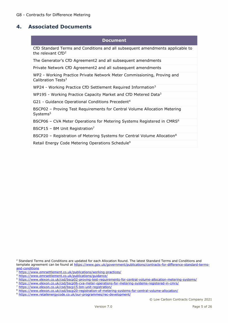
4. Associated Documents
Document
CfD Standard Terms and Conditions and all subsequent amendments applicable to
the relevant CfD2
The Generator’s CfD Agreement2 and all subsequent amendments
Private Network CfD Agreement2 and all subsequent amendments
WP2 - Working Practice Private Network Meter Commissioning, Proving and
Calibration Tests3
WP24 - Working Practice CfD Settlement Required Information3
WP195 - Working Practice Capacity Market and CfD Metered Data3
G21 - Guidance Operational Conditions Precedent4
BSCP02 – Proving Test Requirements for Central Volume Allocation Metering
Systems5
BSCP06 – CVA Meter Operations for Metering Systems Registered in CMRS6
BSCP15 – BM Unit Registration7
BSCP20 – Registration of Metering Systems for Central Volume Allocation8
Retail Energy Code Metering Operations Schedule9
2 Standard Terms and Conditions are updated for each Allocation Round. The latest Standard Terms and Conditions and template agreement can be found at https://www.gov.uk/government/publications/contracts-for-difference-standard-terms-and-conditions 3 https://www.emrsettlement.co.uk/publications/working-practices/ 4 https://www.emrsettlement.co.uk/publications/guidance/ 5 https://www.elexon.co.uk/csd/bscp02-proving-test-requirements-for-central-volume-allocation-metering-systems/ 6 https://www.elexon.co.uk/csd/bscp06-cva-meter-operations-for-metering-systems-registered-in-cmrs/ 7 https://www.elexon.co.uk/csd/bscp15-bm-unit-registration/ 8 https://www.elexon.co.uk/csd/bscp20-registration-of-metering-systems-for-central-volume-allocation/ 9 https://www.retailenergycode.co.uk/our-programmes/rec-development/
G8 - Contracts for Difference Metering
© Low Carbon Contracts Company 2021
Version 7.0 Page 6 of 26
5. What is the Electrical Schematic Obligation?
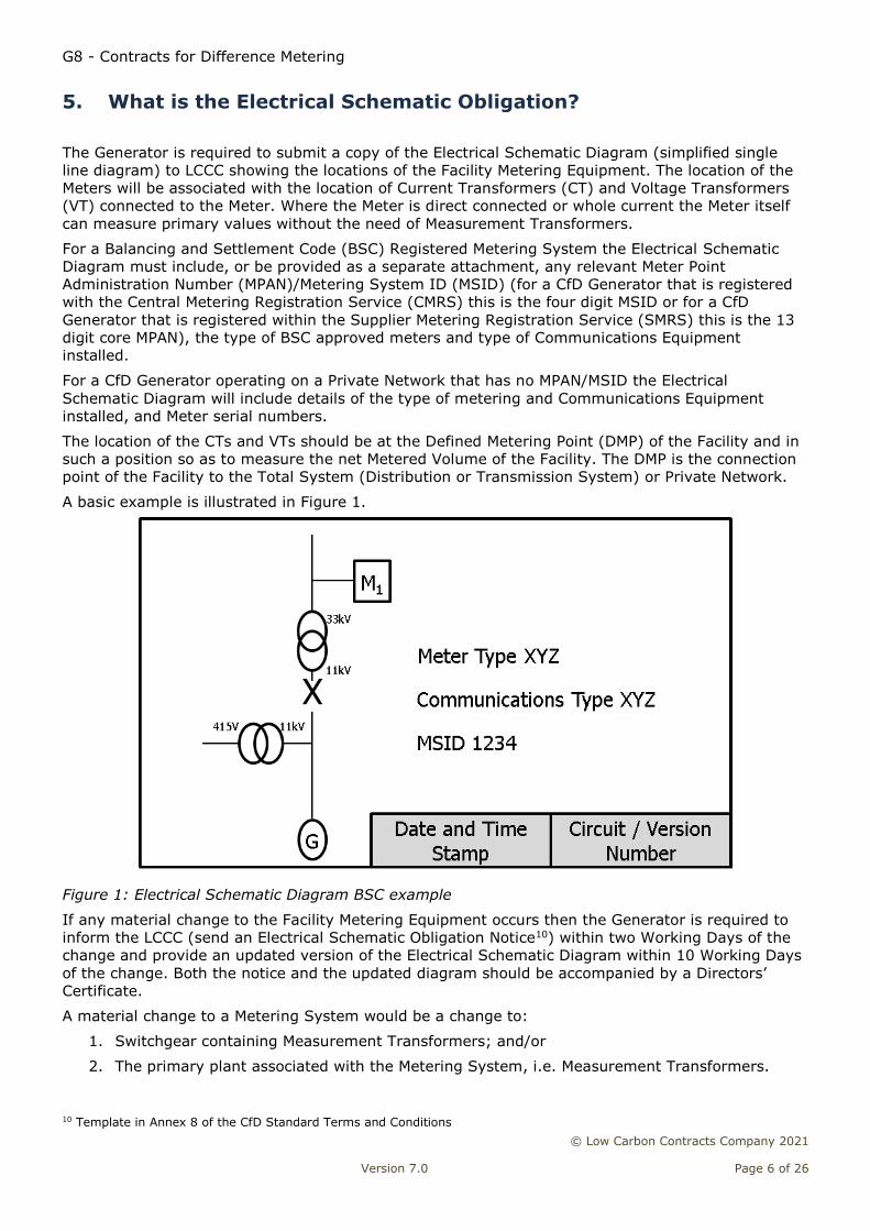
The Generator is required to submit a copy of the Electrical Schematic Diagram (simplified single
line diagram) to LCCC showing the locations of the Facility Metering Equipment. The location of the
Meters will be associated with the location of Current Transformers (CT) and Voltage Transformers
(VT) connected to the Meter. Where the Meter is direct connected or whole current the Meter itself
can measure primary values without the need of Measurement Transformers.
For a Balancing and Settlement Code (BSC) Registered Metering System the Electrical Schematic
Diagram must include, or be provided as a separate attachment, any relevant Meter Point
Administration Number (MPAN)/Metering System ID (MSID) (for a CfD Generator that is registered
with the Central Metering Registration Service (CMRS) this is the four digit MSID or for a CfD
Generator that is registered within the Supplier Metering Registration Service (SMRS) this is the 13
digit core MPAN), the type of BSC approved meters and type of Communications Equipment
installed.
For a CfD Generator operating on a Private Network that has no MPAN/MSID the Electrical
Schematic Diagram will include details of the type of metering and Communications Equipment
installed, and Meter serial numbers.
The location of the CTs and VTs should be at the Defined Metering Point (DMP) of the Facility and in
such a position so as to measure the net Metered Volume of the Facility. The DMP is the connection
point of the Facility to the Total System (Distribution or Transmission System) or Private Network.
A basic example is illustrated in Figure 1.
Figure 1: Electrical Schematic Diagram BSC example
If any material change to the Facility Metering Equipment occurs then the Generator is required to
inform the LCCC (send an Electrical Schematic Obligation Notice10) within two Working Days of the
change and provide an updated version of the Electrical Schematic Diagram within 10 Working Days
of the change. Both the notice and the updated diagram should be accompanied by a Directors’
Certificate.
A material change to a Metering System would be a change to:
1. Switchgear containing Measurement Transformers; and/or
2. The primary plant associated with the Metering System, i.e. Measurement Transformers.
10 Template in Annex 8 of the CfD Standard Terms and Conditions
G8 - Contracts for Difference Metering
© Low Carbon Contracts Company 2021
Version 7.0 Page 7 of 26
A material change for the Electrical Schematic Diagram would also include any equipment on the
diagram, or supporting documents that has been changed resulting in the original diagram, or
supporting document submitted being incorrect.
Examples of a material change are (this list is not exhaustive):
CT or VT ratio;
CT or VT accuracy class or rated burden;
location of the DMP;
switchgear / primary plant;
type of BSC approved Meter used (for a Private Network this would be a Meter serial number
change); and
type of communications system used.
6. What are the metering requirements for CfD Generators
registered in the BSC?
6.1 Metering Requirements
The metering requirements for the Facility Metering Equipment, the Metering Compliance Obligation,
are dependent on whether the Facility is operating under the Balancing and Settlement Code (BSC)
or on a Private Network.
For a BSC Registered Metering System these are11:
‘31.1 With effect from the Start Date, the Generator undertakes to the CfD Counterparty:
(A) To ensure that at all times the Facility Metering Equipment meets all applicable rules and
standards provided for in the BSC;
(B) To ensure that at all times
(i) The Facility Metering Equipment accurately records the BM Unit Metered Volume, such
BM Unit Metered Volume comprising:
(a) All output electricity generated by the Facility; and
(b) All input electricity used by the Facility (excluding, if the Facility is a Dual
Scheme Facility, the Imported Input Electricity); and
(ii) Where the Facility is a Dual Scheme Facility, the Facility Metering Equipment accurately
records all Imported Input Electricity in relation to the Generating Station;
(C) Without prejudice to Conditions 31.1(E)(i) and (F), to ensure that at all times, the Facility
Metering Equipment measures the input and output electricity referred to in Condition 31.1(B)
separately from any other input and output electricity; and
(D) to investigate any fault or issue with the Facility Metering Equipment of which it is notified by
the CfD Counterparty or required to investigate pursuant to the BSC;
(E) to ensure at all times that no Electricity Storage Facility shall be used by or otherwise associated
with the Facility, unless:
(i) such Electricity Storage Facility is associated with a separate BM Unit to the BM Unit
associated with the Facility; or
(ii) subject to Condition 31.1(F), such Electricity Storage Facility is associated with the same
BM Unit as that associated with the Facility and the CfD Counterparty has issued a notice.
11 The metering requirements can change between allocation rounds. This extract has been taken from CfD Standard Terms and Conditions Version 2 - https://www.gov.uk/government/publications/contracts-for-difference-standard-terms-and-conditions-version-2-march-2017. For example, Version 1 of the FiT Contract for Difference standard T&C dated 29 August 2014 had no (E) and (F). For the Investment Contracts before that the Metering Compliance condition is number 30.
G8 - Contracts for Difference Metering
© Low Carbon Contracts Company 2021
Version 7.0 Page 8 of 26
certifying that it is satisfied that the arrangement and installation of the Facility Metering
Equipment is such that the Generator is able to comply with the Condition 31.1(F); and
(F) to ensure at all times that any Electricity Storage Facility, where associated with the same BM
Unit as that associated with the Facility, shall only store electricity generated by the Generating
Unit(s) of the Facility using the Facility Generation Technology and shall not store electricity
imported from any other source.
(each, a “Metering Compliance Obligation” and together the “Metering Compliance
Obligations”).’
For any CfD Generator that is part of the BSC Settlement System the Metering Equipment will meet
the requirements as specified in the BSC Section L12, Retail Energy Code Metering Operations
Schedule13 and the applicable Code of Practice14 (CoP), depending on the capacity of the circuit. The
obligations for calibration, testing and commissioning of Metering Equipment are in CoP4. CfD
Generators can choose to exceed these requirements to install a more robust and accurate Metering
System; for example by installing a Meter of a better accuracy class than the specified minimum.
CfD Generators operating on a Private Network must meet the metering requirements of the CfD
Private Network Agreement. This will be described in Section 9.
For a BSC registered Generator using their Settlement Metering System as the CfD Generator
Facility Metering Equipment the metering arrangement will be compliant with the applicable CoP at
the time of registration for Settlement. In CoP1 and CoP2 if there has been a significant material
change (e.g. replacement of switchgear containing Measurement Transformers) the site is required
to upgrade to the current CoP.
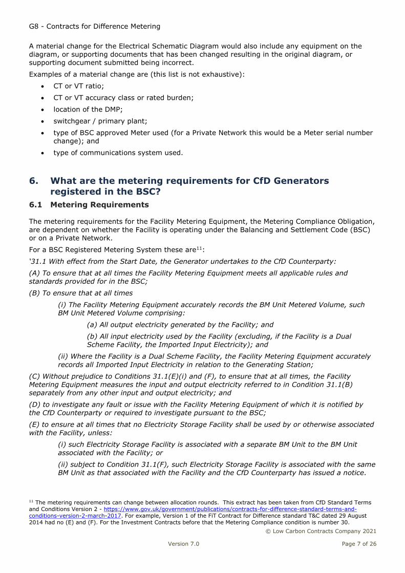
The metering DMP for the CoPs is illustrated in the Single Line Diagram (SLD) example shown in
Figure 2.
Figure 2: Single Line Diagram for a BSC Registered Site
In the example the Generator technology type is Advanced Conversion Technology and has a main
Import/Export Grid Connection for the site. The Facility Metering Equipment is at the single point of
connection and is Metering System15 M1 in the diagram.
Where a site is split between the Facility and other processes not considered to be part of the
Facility the Facility Metered Volumes have to be exclusively metered. For anything that is not
considered part of the Facility a separate Metering System, and registration under the BSC, would
12 https://www.elexon.co.uk/the-bsc/bsc-section-l-metering/ 13 https://www.retailenergycode.co.uk/our-programmes/rec-development/ 14 http://www.elexon.co.uk/bsc-related-documents/related-documents/codes-of-practice/ 15 Only a single Meter shown in the diagram for simplicity. The Metering System requires a Main and a backup Check Meter (i.e. two Meters per circuit)
G8 - Contracts for Difference Metering
© Low Carbon Contracts Company 2021
Version 7.0 Page 9 of 26
have to be provided. It is up to the LCCC to agree what is, or is not, part of the Facility. As a
minimum the Facility must include all the CfD Generating Unit assets and any separate circuits that
provide auxiliary load (i.e. any demand provided to allow the Facility to operate/generate) to that
Generating Unit.
For any Metering System that is connected to the Facility but is separate from the main export
connection (i.e. for a backup emergency supply or a separate site supply that is normally energised)
this will have to be included in the OCP process should LCCC determine that this Metering System
should be considered to be part of the Facility Metering Equipment.
6.2 Meter Data Requirements
The CfD Agreement specifies that the Generator must provide Loss Adjusted Metered Output (LAMO)
to the LCCC. LCCC has appointed EMR Settlement Ltd (EMRS) to receive LAMO and provide the CfD
Settlement Services.
This requires Half Hourly Meters to be used to provide the data used by EMRS. Net Metered Volume
is the Gross Generation less any parasitic site load used by the Generator and losses up to the
metering point. For further guidance on the definition of Installed Capacity and Net Metered volumes
please refer to LCCC’s Installed Capacity guidance16.
For a CMRS site the Metering System will be part of a BM Unit (BMU) and EMRS will receive data via
the normal Settlement process; the CfD Generator need take no action.
For a SMRS site the Metering System will have an MPAN that will be part of a Supplier’s Base BMU.
The CfD Generator will have to request the relevant Supplier to put the MPAN into an Additional BMU
(as per BSCP15) for EMRS to receive the Metered Volumes for the Facility. Once this Additional BMU
has been setup and MPANs allocated to it EMRS will receive data via the normal Settlement process.
This should be done for both the Import and the Export MPAN. The CfD Generator should confirm
with the relevant Supplier that this process has been completed (i.e. that the relevant Supplier has
received the D0294 Confirmation of BM Unit Allocation from the appointed Half Hourly Data
Aggregator).
Where a Metering System is registered in both CMRS and SMRS (i.e. for a Distribution System
connected Facility the export may be registered as a BMU but the import supply is traded in the
Supplier Volume Allocation arrangements and has an MPAN) both of the previous two paragraphs
will be relevant.
For any Metering System that is connected to the Facility but is separate from the main export
connection (i.e. for a backup emergency supply or a separate site supply that is normally energised)
the MPAN will have to be put into an Additional BMU as described above should LCCC determine that
this Metering System should be considered to be part of the Facility Metering Equipment.
The CfD Generator will have to provide the relevant BMU IDs to EMRS to allow them to carry out the
Settlement activity. This is part of the WP24 – Settlement Required Information process and isn’t
discussed in this guidance.
The method for a Private Network CfD Generator is discussed in section 9.
6.3 Adjustment for losses
The LAMO is the net Metered Volume multiplied by any applicable Line Loss Factor (LLF), if
connected to a Distribution System or Transmission Loss Multiplier (TLM) for every Settlement
Period (i.e. every 30 minute period). For Metered Volumes submitted through a BSC process the LLF
and TLM will be applied through the applicable process.
For a CfD Generator connected to a Private Network this will be done by EMRS.
16 https://lowcarboncontracts.uk/pre-generation

G8 - Contracts for Difference Metering
© Low Carbon Contracts Company 2021
Version 7.0 Page 10 of 26
6.4 Metering Faults
The CfD Generator is required under the Metering Compliance Obligation to investigate any fault or
issue with the Facility Metering Equipment of which it is notified by the LCCC or required to
investigate pursuant to the BSC.
Where individual items of Metering Equipment are to be replaced, then only those items need to be
commissioned at that time. Metering Systems in their entirety do not need to be commissioned
when items are replaced within that system unless there is a material change to the Metering
System.
A material change to a Metering System would be a change to:
1. Switchgear containing Measurement Transformers; and/or
2. The primary plant associated with the Metering System, i.e. Measurement
Transformers.
A material change to a CoP1 and CoP2 Metering System would result in the need to ensure that all
items of Metering Equipment comprising that Metering System are compliant with the latest version
of the applicable CoP.
7. What are the metering requirements for CfD Generators
registered in the BSC that are a Dual Scheme
A Dual Scheme Facility is an installation where only part of the site generation is eligible for a CfD
Agreement. In this instance the Facility is the CfD Generator and the Generating Station is the whole
site (i.e. including both the CfD Generator Unit and at least one other Generator Unit that is not part
of the Facility).
The net Metered Volume is the Gross Generation of the Facility less the Estimated Imported
Electricity Allowance. If the CfD contract specifies either a Renewable Qualifying Multiplier (RQM) or
a Combined Heat and Power Qualifying Multiplier (CHPQM) the LAMO is multiplied by this factor.
The Estimated Imported Electricity Allowance is a calculation of the proportion of imported electricity
used by the Facility. It is only to be used when the Facility demand for electricity cannot be
measured separately from the demand of the Generating Station. The metering arrangement for this
scenario is illustrated in the SLD in Figure 3.
G8 - Contracts for Difference Metering
© Low Carbon Contracts Company 2021
Version 7.0 Page 11 of 26
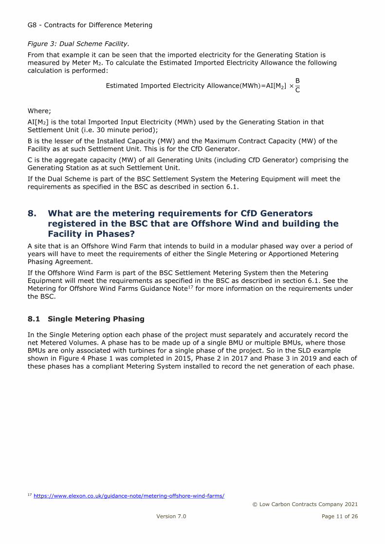
Figure 3: Dual Scheme Facility.
From that example it can be seen that the imported electricity for the Generating Station is
measured by Meter M2. To calculate the Estimated Imported Electricity Allowance the following
calculation is performed:
Estimated Imported Electricity Allowance(MWh)=AI[M2] ×B
C
Where;
AI[M2] is the total Imported Input Electricity (MWh) used by the Generating Station in that
Settlement Unit (i.e. 30 minute period);
B is the lesser of the Installed Capacity (MW) and the Maximum Contract Capacity (MW) of the
Facility as at such Settlement Unit. This is for the CfD Generator.
C is the aggregate capacity (MW) of all Generating Units (including CfD Generator) comprising the
Generating Station as at such Settlement Unit.
If the Dual Scheme is part of the BSC Settlement System the Metering Equipment will meet the
requirements as specified in the BSC as described in section 6.1.
8. What are the metering requirements for CfD Generators
registered in the BSC that are Offshore Wind and building the
Facility in Phases?
A site that is an Offshore Wind Farm that intends to build in a modular phased way over a period of
years will have to meet the requirements of either the Single Metering or Apportioned Metering
Phasing Agreement.
If the Offshore Wind Farm is part of the BSC Settlement Metering System then the Metering
Equipment will meet the requirements as specified in the BSC as described in section 6.1. See the
Metering for Offshore Wind Farms Guidance Note17 for more information on the requirements under
the BSC.
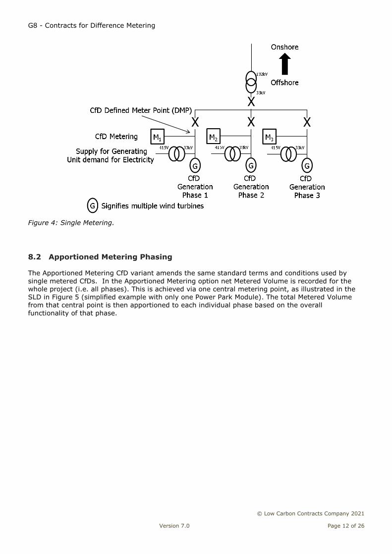
8.1 Single Metering Phasing
In the Single Metering option each phase of the project must separately and accurately record the
net Metered Volumes. A phase has to be made up of a single BMU or multiple BMUs, where those
BMUs are only associated with turbines for a single phase of the project. So in the SLD example
shown in Figure 4 Phase 1 was completed in 2015, Phase 2 in 2017 and Phase 3 in 2019 and each of
these phases has a compliant Metering System installed to record the net generation of each phase.
17 https://www.elexon.co.uk/guidance-note/metering-offshore-wind-farms/
G8 - Contracts for Difference Metering
© Low Carbon Contracts Company 2021
Version 7.0 Page 12 of 26
Figure 4: Single Metering.
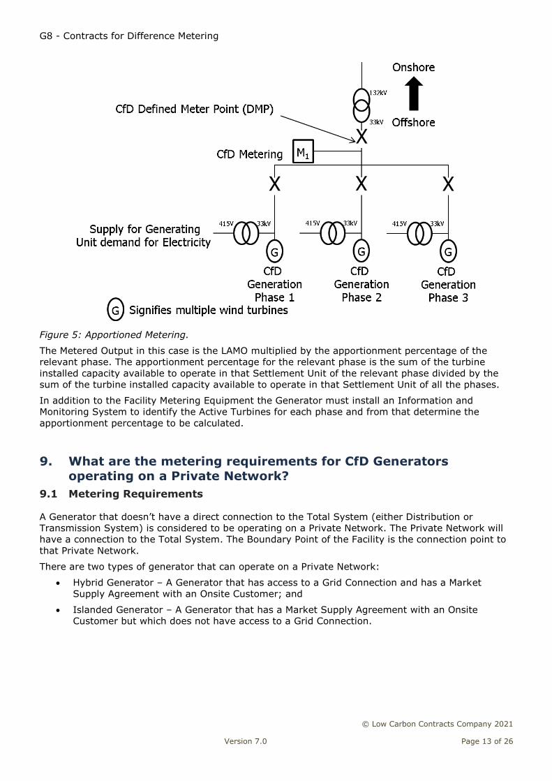
8.2 Apportioned Metering Phasing
The Apportioned Metering CfD variant amends the same standard terms and conditions used by
single metered CfDs. In the Apportioned Metering option net Metered Volume is recorded for the
whole project (i.e. all phases). This is achieved via one central metering point, as illustrated in the
SLD in Figure 5 (simplified example with only one Power Park Module). The total Metered Volume
from that central point is then apportioned to each individual phase based on the overall
functionality of that phase.
G8 - Contracts for Difference Metering
© Low Carbon Contracts Company 2021
Version 7.0 Page 13 of 26
Figure 5: Apportioned Metering.
The Metered Output in this case is the LAMO multiplied by the apportionment percentage of the
relevant phase. The apportionment percentage for the relevant phase is the sum of the turbine
installed capacity available to operate in that Settlement Unit of the relevant phase divided by the
sum of the turbine installed capacity available to operate in that Settlement Unit of all the phases.
In addition to the Facility Metering Equipment the Generator must install an Information and
Monitoring System to identify the Active Turbines for each phase and from that determine the
apportionment percentage to be calculated.
9. What are the metering requirements for CfD Generators
operating on a Private Network?
9.1 Metering Requirements
A Generator that doesn’t have a direct connection to the Total System (either Distribution or
Transmission System) is considered to be operating on a Private Network. The Private Network will
have a connection to the Total System. The Boundary Point of the Facility is the connection point to
that Private Network.
There are two types of generator that can operate on a Private Network:
Hybrid Generator – A Generator that has access to a Grid Connection and has a Market
Supply Agreement with an Onsite Customer; and
Islanded Generator – A Generator that has a Market Supply Agreement with an Onsite
Customer but which does not have access to a Grid Connection.
G8 - Contracts for Difference Metering
© Low Carbon Contracts Company 2021
Version 7.0 Page 14 of 26
For a Metering System on a Private Network the typical18 metering requirements are:
‘31.1 With effect from the Start Date, the Generator undertakes to the CfD Counterparty:
(A) To comply at all times with the MOF and the TSRs;
(B) Where the Facility is a Dual Scheme Facility, to ensure that at all times the Boundary Point
Metering System meets all applicable rules and standards provided for in the BSC;
(C) To ensure that at all times:
(i) The Facility Metering Equipment accurately records the Metered Volume; and
(ii) Where the Facility is a Dual Scheme Facility, the Boundary Point Metering System
accurately records all Imported Input Electricity in relation to the Generating Station;
(D) Without prejudice to Conditions 31.1(H)(ii) and (I), to ensure that at all times the Facility
Metering Equipment measures the input and output electricity referred to in Condition 31.1(C)
separately from any other input and output electricity;
(E) To investigate any fault or issue with the Facility Metering Equipment of which it is notified by
the CfD Counterparty or otherwise required to investigate pursuant to the MOF and the TSRs;
(F) To provide to the CfD Counterparty (or procure that the CfD Counterparty is provided with) the
Metered Volume in relation to each Settlement Unit by the Metered Output Cut-Off Time;
(G) If the Facility is a Dual Scheme Facility, to provide to the CfD Counterparty (or procure that the
CfD Counterparty is provided with) the Imported Input Electricity in relation to each Settlement Unit
by the Metered Output Cut-Off Time;
(H) To ensure at all times that no Electricity Storage Facility shall be used by or otherwise
associated with the Facility, unless:
(i) the electricity produced by or from such Electricity Storage Facility is measured by
metering equipment which is not used by or shared or associated with the Facility Metering
Equipment; or
(ii) subject to Condition 31.1(I), the electricity produced by or from such Electricity Storage
Facility is measured by metering equipment which is used by or shared or associated with
the Facility Metering Equipment and the CfD Counterparty has issued a notice certifying that
it is satisfied that the arrangement and installation of the Facility Metering Equipment is
such that the Generator is able to comply with the Condition 31.1(I); and
(I) to ensure at all times that any Electricity Storage Facility, where the electricity produced by or
from such Electricity Storage Facility is measured by metering equipment which is used by or shared
or associated with the Facility Metering Equipment, shall only store electricity generated by the
Generating Unit(s) of the Facility using the Facility Generation Technology and shall not store
electricity imported from any other source.
(each, a “Metering Compliance Obligation” and together the “Metering Compliance
Obligations”)’.
Where the MOF is the Metering Operational Framework (Annex 6 to the Private Network CfD
Agreement) and the TSR is the Technical System Requirements (Annex 7 to the Private Network CfD
Agreement)
In the CfD Agreement the Generator is referred to as the Facility and the Metering System used to
measure net Metered Volume is the Facility Metering Equipment. The DMP is at the Boundary
Point(s) of the Facility.
18 The extract quoted above is taken from CfD Private Network Agreement Version 2 - https://www.gov.uk/government/publications/contracts-for-difference-standard-terms-and-conditions-version-2-march-2017. There are no private wire agreements from the first Allocation Round or the Investment Contracts.
G8 - Contracts for Difference Metering
© Low Carbon Contracts Company 2021
Version 7.0 Page 15 of 26
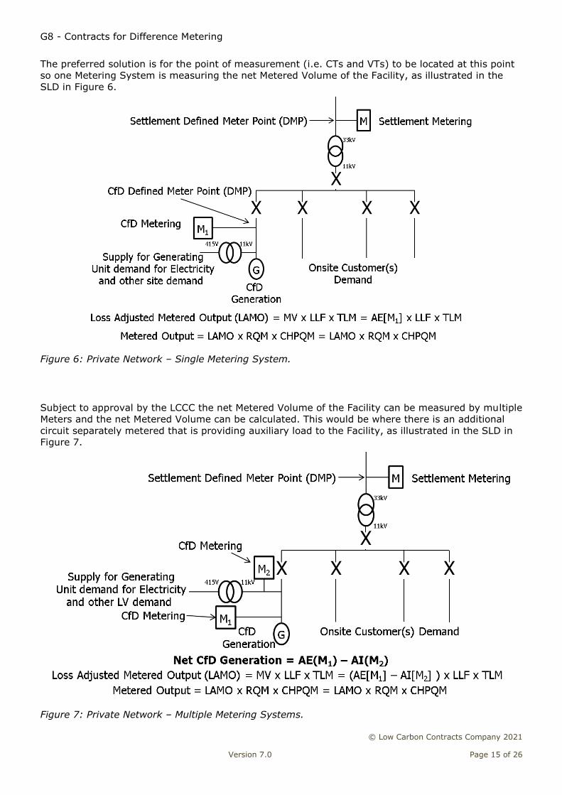
The preferred solution is for the point of measurement (i.e. CTs and VTs) to be located at this point
so one Metering System is measuring the net Metered Volume of the Facility, as illustrated in the
SLD in Figure 6.
Figure 6: Private Network – Single Metering System.
Subject to approval by the LCCC the net Metered Volume of the Facility can be measured by multiple
Meters and the net Metered Volume can be calculated. This would be where there is an additional
circuit separately metered that is providing auxiliary load to the Facility, as illustrated in the SLD in
Figure 7.
Figure 7: Private Network – Multiple Metering Systems.
G8 - Contracts for Difference Metering
© Low Carbon Contracts Company 2021
Version 7.0 Page 16 of 26
From these Meters the net Metered Volume can be derived as follows:
Net Metered Volume(MWh)=Gross Generation(MWh)-Auxiliary Load(MWh)
This is not the preferred option of the LCCC but an option that will be allowed if the LCCCs
nominated representative is satisfied either from the SLD or at the witnessing of commissioning and
proving tests of the Metering System that net Metered Volume can be accurately recorded and
reported.
The Meter must be connected so that it is normally energised to allow interrogation for EMR
settlement purposes.
It is recommended for a Data Collector (e.g. a Half Hourly Data Collector operating in the BSC) to
download the Metered Volumes daily and submit the data, in a defined format, to EMRS.
A CfD Generator operating on a Private Network must meet the additional requirements of the
Private Network Metering Operational Framework (MOF) and the Technical System Requirements
(TSR) in their CfD Agreement (Annex 6 & 7)19. This includes the minimum specification that the
Metering Equipment requires to be and the testing and commissioning requirements.
The Generator is responsible for sealing of the Metering Equipment. This includes the Meters,
Outstation, panel doors; potential fuses and test terminal facilities if not contained within a metering
panel. A Re-Sealing Form (MOF Appendix 1) must be maintained and updated by the Generator. If
any seal is broken or damaged the LCCC shall be notified.
9.2 Metering Equipment
Any Generator can choose to exceed the requirements specified in the TSR and install a more robust
and accurate Metering System; for example, by installing a Meter of a better accuracy class than the
specified minimum.
The TSR is split into three Metering Types based on the rated capacity of the circuit:
1. Metering Type 1 - for circuits rated greater than 100MVA;
2. Metering Type 2 - for circuits rated up to 100MVA and rated greater than 10VA; and
3. Metering Type 3 - for circuits rated up to 10MVA.
It will depend on what Metering Type category a Facility falls into as to what Metering Equipment will
have to be installed and what limit of Overall Accuracy will be applicable.
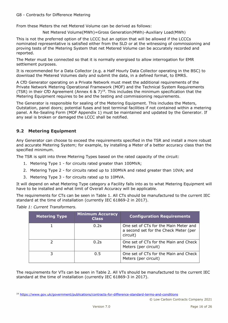
The requirements for CTs can be seen in Table 1. All CTs should be manufactured to the current IEC
standard at the time of installation (currently IEC 61869-2 in 2017).
Table 1: Current Transformers.
Metering Type Minimum Accuracy
Class Configuration Requirements
1 0.2s One set of CTs for the Main Meter and
a second set for the Check Meter (per
circuit)
2 0.2s One set of CTs for the Main and Check
Meters (per circuit)
3 0.5 One set of CTs for the Main and Check
Meters (per circuit)
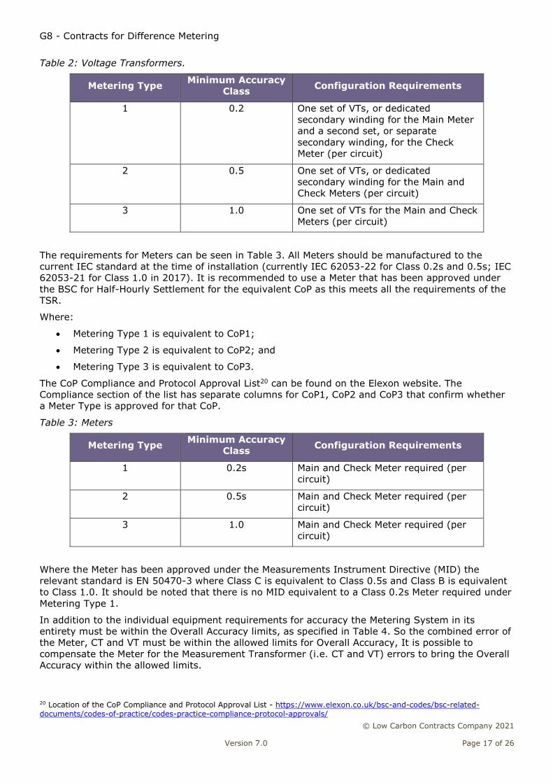
The requirements for VTs can be seen in Table 2. All VTs should be manufactured to the current IEC
standard at the time of installation (currently IEC 61869-3 in 2017).
19 https://www.gov.uk/government/publications/contracts-for-difference-standard-terms-and-conditions
G8 - Contracts for Difference Metering
© Low Carbon Contracts Company 2021
Version 7.0 Page 17 of 26
Table 2: Voltage Transformers.
Metering Type Minimum Accuracy
Class Configuration Requirements
1 0.2 One set of VTs, or dedicated
secondary winding for the Main Meter
and a second set, or separate
secondary winding, for the Check
Meter (per circuit)
2 0.5 One set of VTs, or dedicated
secondary winding for the Main and
Check Meters (per circuit)
3 1.0 One set of VTs for the Main and Check
Meters (per circuit)
The requirements for Meters can be seen in Table 3. All Meters should be manufactured to the
current IEC standard at the time of installation (currently IEC 62053-22 for Class 0.2s and 0.5s; IEC
62053-21 for Class 1.0 in 2017). It is recommended to use a Meter that has been approved under
the BSC for Half-Hourly Settlement for the equivalent CoP as this meets all the requirements of the
TSR.
Where:
Metering Type 1 is equivalent to CoP1;
Metering Type 2 is equivalent to CoP2; and
Metering Type 3 is equivalent to CoP3.
The CoP Compliance and Protocol Approval List20 can be found on the Elexon website. The
Compliance section of the list has separate columns for CoP1, CoP2 and CoP3 that confirm whether
a Meter Type is approved for that CoP.
Table 3: Meters
Metering Type Minimum Accuracy
Class Configuration Requirements
1 0.2s Main and Check Meter required (per
circuit)
2 0.5s Main and Check Meter required (per
circuit)
3 1.0 Main and Check Meter required (per
circuit)
Where the Meter has been approved under the Measurements Instrument Directive (MID) the
relevant standard is EN 50470-3 where Class C is equivalent to Class 0.5s and Class B is equivalent
to Class 1.0. It should be noted that there is no MID equivalent to a Class 0.2s Meter required under
Metering Type 1.
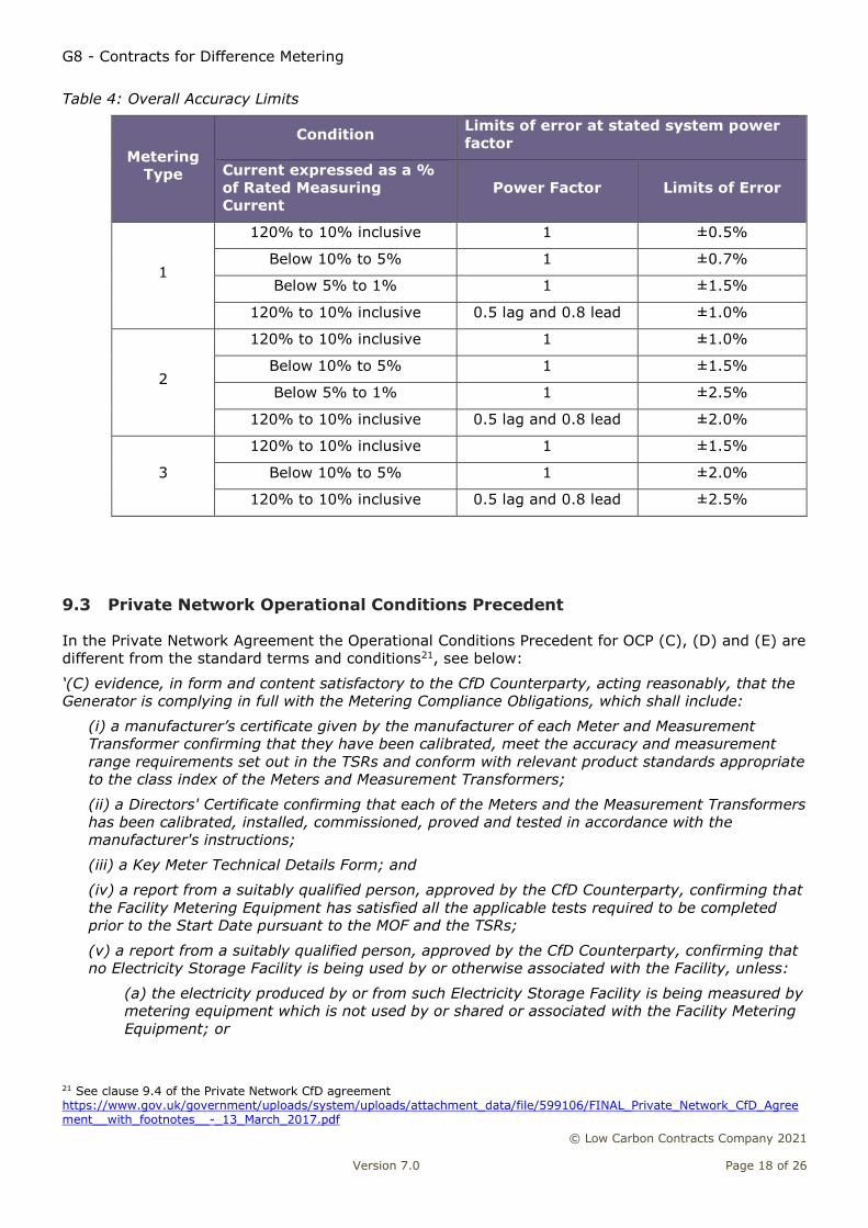
In addition to the individual equipment requirements for accuracy the Metering System in its
entirety must be within the Overall Accuracy limits, as specified in Table 4. So the combined error of
the Meter, CT and VT must be within the allowed limits for Overall Accuracy, It is possible to
compensate the Meter for the Measurement Transformer (i.e. CT and VT) errors to bring the Overall
Accuracy within the allowed limits.
20 Location of the CoP Compliance and Protocol Approval List - https://www.elexon.co.uk/bsc-and-codes/bsc-related-documents/codes-of-practice/codes-practice-compliance-protocol-approvals/
G8 - Contracts for Difference Metering
© Low Carbon Contracts Company 2021
Version 7.0 Page 18 of 26
Table 4: Overall Accuracy Limits
Metering
Type
Condition Limits of error at stated system power
factor
Current expressed as a %
of Rated Measuring
Current
Power Factor Limits of Error
1
120% to 10% inclusive 1 ±0.5%
Below 10% to 5% 1 ±0.7%
Below 5% to 1% 1 ±1.5%
120% to 10% inclusive 0.5 lag and 0.8 lead ±1.0%
2
120% to 10% inclusive 1 ±1.0%
Below 10% to 5% 1 ±1.5%
Below 5% to 1% 1 ±2.5%
120% to 10% inclusive 0.5 lag and 0.8 lead ±2.0%
3
120% to 10% inclusive 1 ±1.5%
Below 10% to 5% 1 ±2.0%
120% to 10% inclusive 0.5 lag and 0.8 lead ±2.5%
9.3 Private Network Operational Conditions Precedent
In the Private Network Agreement the Operational Conditions Precedent for OCP (C), (D) and (E) are
different from the standard terms and conditions21, see below:
‘(C) evidence, in form and content satisfactory to the CfD Counterparty, acting reasonably, that the
Generator is complying in full with the Metering Compliance Obligations, which shall include:
(i) a manufacturer’s certificate given by the manufacturer of each Meter and Measurement
Transformer confirming that they have been calibrated, meet the accuracy and measurement
range requirements set out in the TSRs and conform with relevant product standards appropriate
to the class index of the Meters and Measurement Transformers;
(ii) a Directors' Certificate confirming that each of the Meters and the Measurement Transformers
has been calibrated, installed, commissioned, proved and tested in accordance with the
manufacturer's instructions;
(iii) a Key Meter Technical Details Form; and
(iv) a report from a suitably qualified person, approved by the CfD Counterparty, confirming that
the Facility Metering Equipment has satisfied all the applicable tests required to be completed
prior to the Start Date pursuant to the MOF and the TSRs;
(v) a report from a suitably qualified person, approved by the CfD Counterparty, confirming that
no Electricity Storage Facility is being used by or otherwise associated with the Facility, unless:
(a) the electricity produced by or from such Electricity Storage Facility is being measured by
metering equipment which is not used by or shared or associated with the Facility Metering
Equipment; or
21 See clause 9.4 of the Private Network CfD agreement https://www.gov.uk/government/uploads/system/uploads/attachment_data/file/599106/FINAL_Private_Network_CfD_Agreement__with_footnotes__-_13_March_2017.pdf
G8 - Contracts for Difference Metering
© Low Carbon Contracts Company 2021
Version 7.0 Page 19 of 26
(b) subject to Condition 31.1(I), where the electricity produced by or from such Electricity
Storage Facility is being measured by metering equipment which is used by or shared or
associated with the Facility Metering Equipment, the CfD Counterparty has issued a notice
certifying that it is satisfied that the arrangement and installation of the Facility Metering
Equipment is such that the Generator is able to comply with the Condition 31.1(I); and
(vi) a report from a suitably qualified person, approved by the CfD Counterparty confirming that
where electricity produced by or from an Electricity Storage Facility is being measured by
metering equipment which is being used by or shared or associated with the Facility Metering
Equipment, such Electricity Storage Facility is only storing electricity generated by the
Generating Unit(s) of the Facility using the Facility Generation Technology and does not store
electricity imported from any other source.
(D) a date and time stamped copy of the electrical schematic diagram, certified as being correct and
up-to-date by a director of the Generator and showing the locations of the Facility Metering
Equipment associated with all assets comprised within the Facility (including: details of the type of
metering and Communications Equipment installed in compliance with the Metering Compliance
Obligation; and the Meter Serial Number for each of the Meters); and
(E) evidence, in form and content satisfactory to the CfD Counterparty, acting reasonably, that all
Communications Equipment relating to Facility Metering Equipment is satisfactorily installed,
commissioned, configured, operational, maintained, tested and are fully compliant with the
applicable TSRs.’
The Key Meter Technical Details are the Meter serial numbers, the Outstation number of channels,
the measurement quantity ID (e.g. AE for Active Export), the Meter multiplier, the pulse multiplier,
the CT and/or VT serial numbers and the CT and/or VT ratios.
9.4 Adjustment for Losses
The LAMO will be adjusted for LLF and TLM by EMRS. LLF shall be applied based on the voltage class
of the Facility. The voltage class is the voltage (kV) level at the connection point of the Facility to the
Private Network. The LLF used will be an LLF for equivalent voltage level in that Grid Supply Point
(GSP).
TLM will be applied based on the GSP the Facility is located.
9.5 Metering Faults
The CfD Generator is required under the Metering Compliance Obligation to investigate any fault or
issue with the Facility Metering Equipment of which it is notified by the LCCC or otherwise required
to investigate pursuant to the MOF and the TSRs.
Where individual items of Metering Equipment are to be replaced, then only those items need to be
commissioned at that time. Metering Systems in their entirety do not need to be commissioned
when items are replaced within that system unless there is a material change to the Metering
System.
A material change to a Metering System would be a change to:
1. Switchgear containing Measurement Transformers; and/or
2. The primary plant associated with the Metering System, i.e. Measurement
Transformers.
A material change to a Metering System would result in the need to ensure that all items of Metering
Equipment comprising that Metering System are compliant with the latest version of the MOF / TSR.
G8 - Contracts for Difference Metering
© Low Carbon Contracts Company 2021
Version 7.0 Page 20 of 26
10. What are the test facility requirements?
For any CfD Generator that has its Metering Equipment registered in Settlements the test facilities
must meet the requirements as specified in the applicable CoP22 as a minimum, depending on the
capacity of the circuit.
For any CfD Generator that is operating on a Private Network the test facilities must meet the
requirements of the MOF and the TSR specified in the terms of the CfD Agreement as a minimum,
depending on the capacity of the circuit.
The Meter(s) are connected to the secondary side of the CTs and/or VTs via test terminal facilities
and in the case of voltage connections also via fuses. These facilities should be configured so as to
allow the Meter(s) to be isolated while the circuit is energised for test purposes or replacing the
Meters.
For CoP1 and CoP2 Metering Systems (and Type 1 Metering Systems on Private Networks) separate
testing facilities shall be provided for the main and check Meters, this allows one Meter to be worked
on or removed while the other continues to measure the prevailing load. For CoP3 Metering Systems
(and Type 2, Type 3 Metering Systems on Private Networks) testing facilities shall be provided close
by the Meters of each circuit.
If the option of using a second set of CTs for the check Meters is used in a Private Network Type 2
site separate testing facilities will be required for the main and check Meters. Effectively the testing
facilities required are a separate test facility for each set of metering CTs. For all situations the
Meters are separately fused. This is a minimum requirement and any CfD Generator in a CoP3 site
or a Type 2, Type 3 Private Network site can install separate testing facilities for the main and check
Meters should they wish, irrelevant of the number of sets of metering CTs installed.
Examples of test facilities can be seen in Figures 8, 9, 10 and 11.
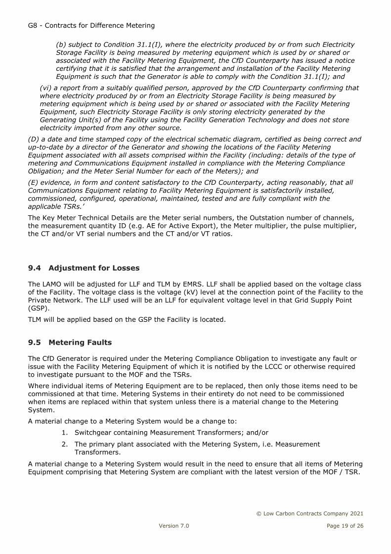
Figure 8: Test Facilities Example - CoP 1 and Private Network Type 1
Figure 8 is an example of the minimum testing facilities required for a CoP1 and a Private Network
Type 1 installation. A set of multi-core cables will come from the main VT or main winding for the
main Meter and another set of multi-core cables will come from the check VT or check winding for
the check Meter. Any other burden connected to the VT would be connected to the check winding
and separately fused.
22 http://www.elexon.co.uk/bsc-related-documents/related-documents/codes-of-practice/
G8 - Contracts for Difference Metering
© Low Carbon Contracts Company 2021
Version 7.0 Page 21 of 26
A set of multi-core cables will come from the main CT or main winding for the main Meter and
another set of multi-core cables will come from the check CT or check winding for the check Meter.
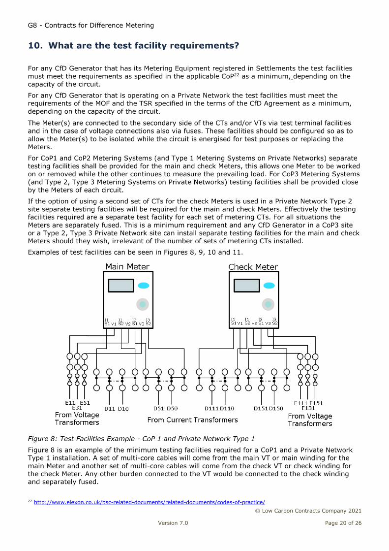
Figure 9: Test Facilities Example – CoP2 and Private Network Type 2 (separate CTs)
Figure 9 is an example of the minimum testing facilities required for a CoP2 and Type 2 Private
Network installation. If a second set of CTs and/or VTs is used for the check Meter, refer to Figure 8.
One set of multi-core cables will come from the VT and be used for main and check Meter. The
connections will be separated in the metering panel.
Any other burden connected to the VT must be connected to another winding and separately fused.
Figure 10: Test Facilities Example – CoP3 and Private Network Type 2 (one set of CTs) and Type 3
G8 - Contracts for Difference Metering
© Low Carbon Contracts Company 2021
Version 7.0 Page 22 of 26
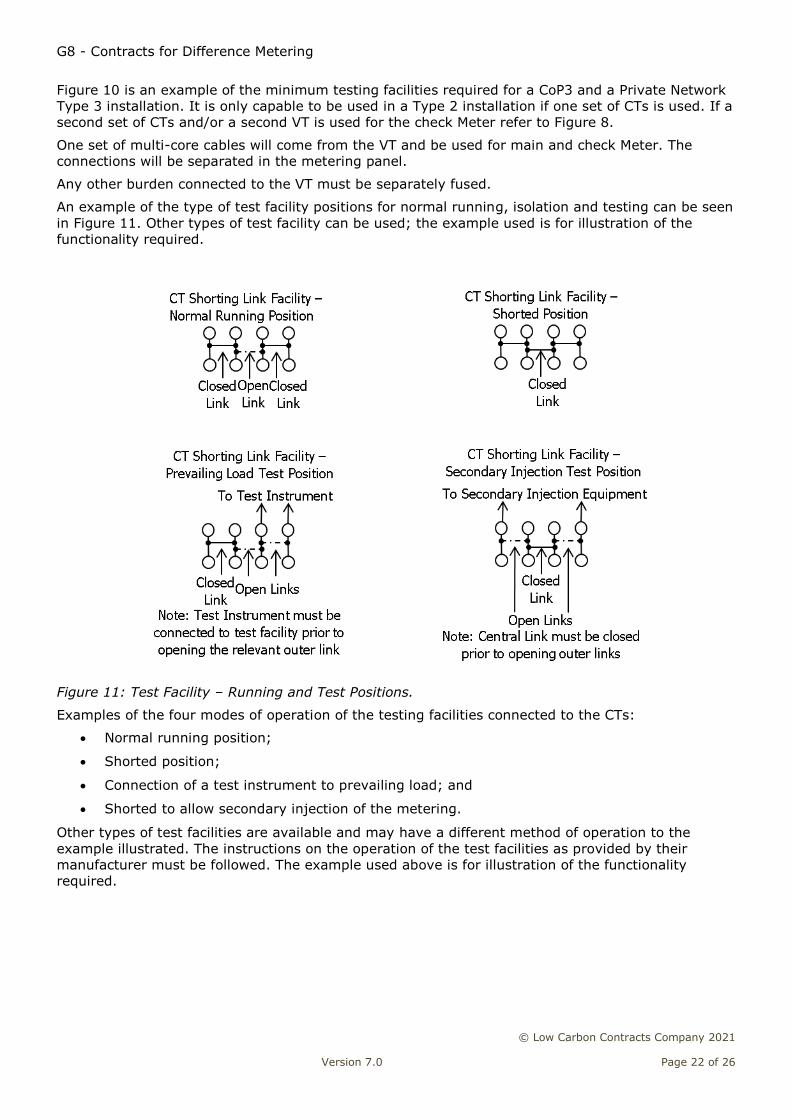
Figure 10 is an example of the minimum testing facilities required for a CoP3 and a Private Network
Type 3 installation. It is only capable to be used in a Type 2 installation if one set of CTs is used. If a
second set of CTs and/or a second VT is used for the check Meter refer to Figure 8.
One set of multi-core cables will come from the VT and be used for main and check Meter. The
connections will be separated in the metering panel.
Any other burden connected to the VT must be separately fused.
An example of the type of test facility positions for normal running, isolation and testing can be seen
in Figure 11. Other types of test facility can be used; the example used is for illustration of the
functionality required.
Figure 11: Test Facility – Running and Test Positions.
Examples of the four modes of operation of the testing facilities connected to the CTs:
Normal running position;
Shorted position;
Connection of a test instrument to prevailing load; and
Shorted to allow secondary injection of the metering.
Other types of test facilities are available and may have a different method of operation to the
example illustrated. The instructions on the operation of the test facilities as provided by their
manufacturer must be followed. The example used above is for illustration of the functionality
required.
G8 - Contracts for Difference Metering
© Low Carbon Contracts Company 2021
Version 7.0 Page 23 of 26
11. What are the Meter setup requirements?
As a minimum the Half Hourly Meter must record Active Import (AI) and Active Export (AE) on a half
hourly basis (i.e. an AI and AE load profile channel). If the Meter is also being used for BSC
Settlement purposes, there will be a requirement to record Reactive Energy in addition.
All data will be in a Settlement Period format. This will be of 30 minute duration starting on the hour
or half hour; there will be 48 periods in a day starting at 00:00hrs. Each Settlement Period will be in
energy format (e.g. multiples of Wh).
The Meter time will be set to Co-ordinated Universal Time (UTC), also known as Greenwich Mean
Time (GMT). No switching between UTC and British Summer Time (BST) shall occur for Settlement
Period data storage within the Meter.
The display of the Meter will have a cumulative AI and AE register (if used for BSC purposes there
will be Reactive Energy registers in addition), the CT & VT ratios, current date and time as a
minimum.
12. How do I submit my aggregation rules?
For EMRS to be able to create an aggregation rule for the CfD Facility the information required
depends on the way the Metering System has been Registered or whether it is a Private Network.
For a CMRS Registered Metering System(s) you will need to submit the BMU ID(s) being used by the
Facility.
For an SMRS Registered Metering System(s) you will need to submit the Additional BMU ID(s) used
by the Facility. Note: the Import and Export MPANs may be in separate BMUs and require
two Additional BMU IDs to be submitted.
For a Private Network CfD you will need to submit the CSV file identifier, the Grid Supply Point area
the Facility is located and the voltage class of the Facility.
Note: It is possible for the active export energy to be Registered in CMRS and the active
import energy Registered in SMRS. In this case the aggregation rule will have an
Embedded BMU (i.e. E_) for the export and an Additional BMU for CfD Assets (i.e. C_) for
the import.
The relevant information should be submitted to the EMRS Metering Team to create the aggregation
rule for the CfD Facility and we will send it to the CfD Generator to confirm it is acceptable. The
aggregation rule is required for the OCP (A) Settlement Required Information process23.
23 WP24 – CfD Settlement Required Information process https://www.emrsettlement.co.uk/publications/working-practices/
G8 - Contracts for Difference Metering
© Low Carbon Contracts Company 2021
Version 7.0 Page 24 of 26
13. What if my metering arrangements change?
The CfD Generator has to maintain the Metering Compliance Obligation and will have to provide
evidence to LCCC to demonstrate continued compliance where any changes have occurred to the
Metering Equipment or arrangements since the OCP was completed.
LCCC will request the EMRS Metering Team to validate the requests and confirm compliance.
A change proposed by a Capacity Provider or a CfD Generator will require information to be
submitted to be able to carry out the validation checks. This can be a combination of an aggregation
rule change and a Metering Equipment change or only one of these elements.
The lists below are split for aggregation rule changes and Metering Equipment changes.
NOTE: You may have to request elements of both depending on the nature of the change.
NOTE: Where any change impacts the Electrical Schematic Diagram the change will also
have to follow the Electrical Schematic Obligation process – see Section 5.
13.1 Aggregation Rule Changes
The aggregation rule should be submitted for review to the EMRS Metering Team. The information
required and checks carried out are as follows:
MPAN Change
ECOES check on new MPAN and the Effective from Date of the new MPAN.
BM Unit Change
BMU ID check on registered BM Unit list found on the Elexon Portal24; and
The Effective from Date of the new BMU ID.
CSV File Metered Entity ID Change (for Private Network CfD)
ECOES check for any Boundary Point MPANs and LLF values; and
CSV file for new identifier and format check; and the Effective from Date of the new
identifier.
Switch from SMRS to CMRS Metering
Requires the current MPAN and the new BMU ID and the Effective from Date of the new BMU
ID; and
BMU ID check on registered BM Unit list found on the Elexon Portal.
Switch from CMRS to SMRS Metering
Requires the current BMU ID and the new MPAN with Effective from Date; and
ECOES check on new MPAN.
Addition of a new Metering System
Require the additional BMU ID/MPAN/ CSV file identifier as applicable and Effective from
Date. Follow relevant procedure above.
24 https://www.elexonportal.co.uk/
G8 - Contracts for Difference Metering
© Low Carbon Contracts Company 2021
Version 7.0 Page 25 of 26
13.2 Metering Equipment Changes
The EMRS Metering Team act on behalf of LCCC in the approval of change related to the metering
arrangements for the CfD Facility.
Depending on the nature of the Metering Equipment change a full OCP check may be required or
where only an element (e.g. a Meter) has been changed only a partial check is required.
The information required is as follows:
Meter Change
Meter Calibration Certificates;
Metering Commissioning Records;
Meter Proving Test; and
Meter Technical Details (D0268 or BSCP20 Key Meter Technical Details Form for Private
Network CfD).
Measurement Transformer Change
Measurement Transformer Calibration Certificates;
Measurement Transformer Commissioning Records (if multi-ratio evidence required on what
ratio has been selected);
Measurement Transformer error compensation calculations and evidence of compensation
values programmed into Meter;
Measurement Transformer Burdens;
Meter Technical Details (if ratio change - D0268 or BSCP20 or Key Meter Technical Details
Form for Private Network CfD); and
Meter Commissioning Records.
Metering System change (Meters and Measurement Transformers)
All information listed in Meter Change and Measurement Transformer Change is required.
Should all validation tests be competed and continued compliance with the Agreement and relevant
Governing Documents demonstrated a compliance notification will be issued.
If compliance with the Agreement and relevant Governing Documents is not demonstrated a non-
compliance notification will be issued and the CfD Generator will have to resolve the issues
identified.
14. Need more information
For more information, please visit our website www.emrsettlement.co.uk or email us at