g3 electronic displays its innovations - sitek.fi¤nnät.pdf · the g3 series product line is a...
TRANSCRIPT

G3 Electronics
G3 Electronic displays its innovations !
Graphic Display for configuration & diagnostics
Highly DistributableAuto Recovery Module Easy, Robust Connections
Commissioning Capabilities Visual Diagnostics• Setnetworkaddress
• Setbaudrate
• SetautoormanualI/Osizes
• Setfault/idleoutputstates
• Setbrightness
• Setfactorydefaults
• Shortedandopenloaddetection
• Shortedsensor/cabledetection
• Low&missingpowerdetection
• Missingmoduledetection
• Self-testactivation
• Logofnetworkerrors/
Distributionerrors
Benefits:•SPEEDCONM12connectortechnologyallowsforfastandefficient½turnI/Oconnectorinsertion•Powerconnectorschemeallowsoutputpowertoberemovedwhileinputsandcommunicationareleftactive•IP65/NEMA4Protection•AutoRecoveryModule(ARM)protectsconfigurationinformationduringacriticalfailure•Novel“clip”designallowseasymoduleremoval/replacementwithoutdismantlingmanifold•Interfacesto503valveswithflowfrom1200l/mn(ISOsubbase)upto1400l/mnANR(high-flowsubbase)•“Online”CADfiles,85formats
Innovative Graphic Display is used for easy commissioning,
visual status & diagnostics
0056
0GB
-201
2/R
03A
vaila
bilit
y,d
esig
nan
dsp
ecifi
catio
nsa
res
ubje
ctto
cha
nge
with
outn
otic
e.A
llrig
hts
rese
rved
.
G3 Electronics
37www.asconumatics.eu
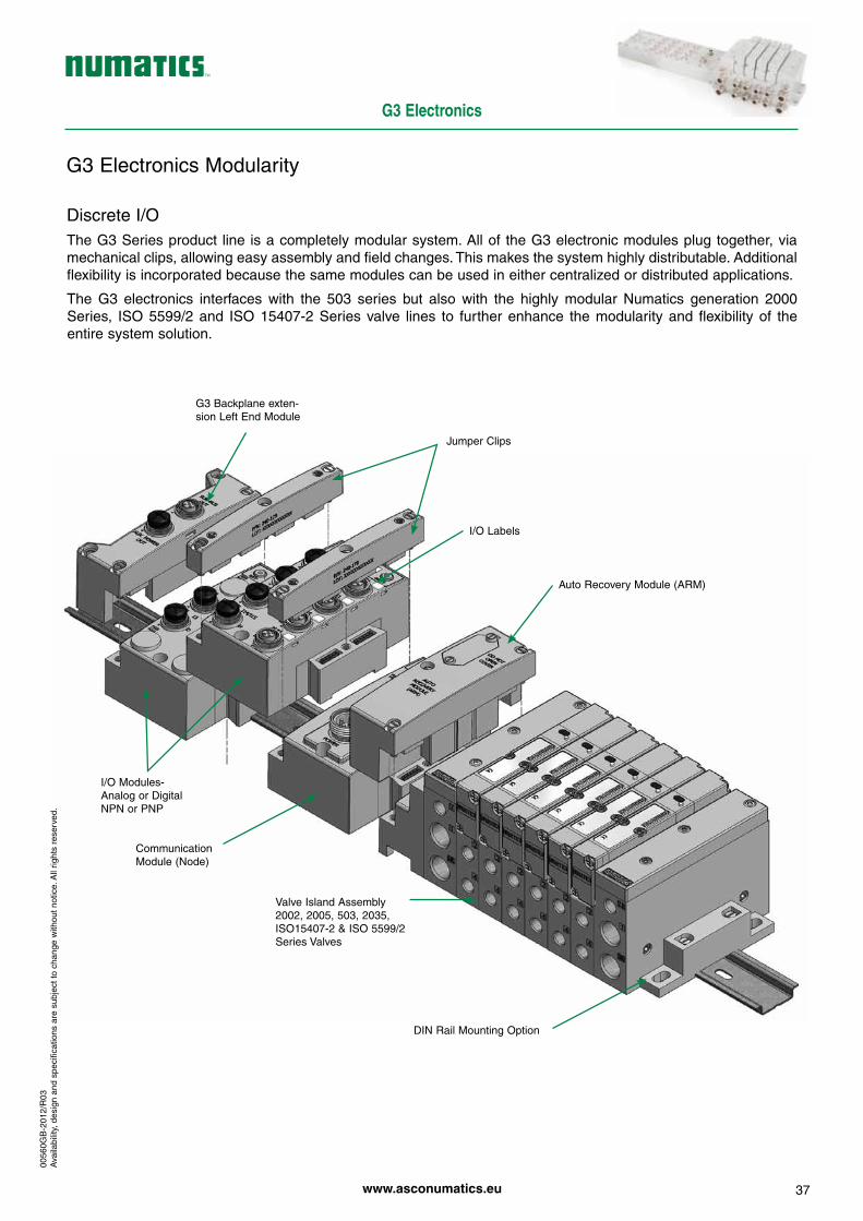
G3ElectronicsModularity
DiscreteI/OTheG3Seriesproduct line isacompletelymodularsystem.Allof theG3electronicmodulesplugtogether,viamechanicalclips,allowingeasyassemblyandfieldchanges.Thismakesthesystemhighlydistributable.Additionalflexibilityisincorporatedbecausethesamemodulescanbeusedineithercentralizedordistributedapplications.
The G3 electronics interfaces with the 503 series but also with the highly modular Numatics generation 2000Series, ISO5599/2and ISO15407-2Seriesvalve lines to furtherenhance themodularityand flexibilityof theentiresystemsolution.
ValveIslandAssembly2002,2005,503,2035,ISO15407-2&ISO5599/2SeriesValves
CommunicationModule(Node)
I/OModules-AnalogorDigitalNPNorPNP
DINRailMountingOption
AutoRecoveryModule(ARM)
I/OLabels
JumperClips
G3Backplaneexten-sionLeftEndModule
0056
0GB
-201
2/R
03A
vaila
bilit
y,d
esig
nan
dsp
ecifi
catio
nsa
res
ubje
ctto
cha
nge
with
outn
otic
e.A
llrig
hts
rese
rved
.

G3 Electronics
38
G3PlatformDistributionOptions
Easy, Cost Effective Solutions for Digital I/O and Valve Automation using G3 Electronics
MainFieldbusIsland
Backplane extension
Backplane extension Out
Backplane extension Out
Backplane extension In
Backplane extension
I/OOnly DistributedIslandwithI/O&Valves
DistributedIslandwithValves
24VDCPowerSupply
24VDCPowerSupply(optional
forInputmodules)
24VDCPowerSupply
Distribution Benefits
• Upto256Inputs/544Output(1200bits)capabilitywithonecommunicationnode!
• 32valvesolenoidpermanifoldupto16manifoldspercommunicationnode!
• Onenodesupports16I/Omodules-AnalogI/O,DigitalI/O(NPN&PNP)
• Uniquedistributionsystemallowssystemefficiencybyallowingthesamemodulestobeusedineithercentralizedordistributedapplications
G3 supported protocols :• DeviceNet™• EtherNet/IP™• PROFIBUSDP• PROFINET• POWERLINK
• ModbusTCP• CANopen®• DeviceNet™ w/DeviceLogix• EtherCAT®
G2-2 supported protocols :• InterbusS• ControlNet• FieldbusFoundation• AS-interface
0056
0GB
-201
2/R
04A
vaila
bilit
y,d
esig
nan
dsp
ecifi
catio
nsa
res
ubje
ctto
cha
nge
with
outn
otic
e.A
llrig
hts
rese
rved
.

G3 Electronics
39www.asconumatics.eu
G3PlatformDistributionOptions
TheG3platformisflexibletothepointthatthereareavirtuallyinfinitenumberofI/OdistributionoptionsusingthefewbasicG3modules.Thefollowingbasicrulesshouldbefollowedintheconfigurationofyourcontrolarchi-tecture.
ValveSide•Uptoatotalof32valvesolenoidscanbedrivenin amanifoldassemblyintegratedintotheMainFieldbus Island.Thiscanbeanynumberofsingleordouble solenoidvalveswithatotalnumberofsolenoidsnotto exceed32.
I/OSideDistribution•Atotalof16modulescanbeintegratedintothenetworkandcontrolledbythemainfieldbuscommunicationmodule(Node)
• Modules include analog and digital I/O modules providingaddressingcapacityforupto256Inputs/544Outputs(1200bits)pernode.
•Uniquedistributionsystemallowssystemefficiencybyallow-ingthesamemodulestobeusedineithercentralizedordis-tributedapplications
•DistributionoptionsincludeInputsonly,Outputsonly,I/Oonly,valveswithInputs,valveswithOutputsandvalveswithI/O
• Configurationcanincludeupto16ofthe followingmodules: -DigitalI/Omodules -Backplaneextensionvalvemodules -AnalogI/Omodules
Comm.Module
I/OSide
16 Modules can be supported on this side of the comm. module
MainfieldbusComm.Module
TypicalMainFieldbusIsland
Comm.Module
ValveSide
I/OSide
EtherNet/IPNetwork
EtherNet/IP
distributedisland
distributedisland
distributedisland
Exampleofplatformdistribution
EtherNet/IP EtherNet/IP
0056
0GB
-201
2/R
03A
vaila
bilit
y,d
esig
nan
dsp
ecifi
catio
nsa
res
ubje
ctto
cha
nge
with
outn
otic
e.A
llrig
hts
rese
rved
.
yesterday today

G3 Electronics
40
DeviceNet™
DeviceNet™ is an open bus fieldbus communicationsystem developed by Allen-Bradley based on ControllerArea Network (CAN) technology. The governing bodyfor DeviceNet™ is the Open DeviceNet™ VendorsAssociation(ODVA).TheODVAcontrolstheDeviceNet™specificationandoverseesproductconformancetesting.
Numatics’ G3 DeviceNet™ nodes have an integratedgraphicdisplayandarecapableofaddressingcombina-tionsofupto256inputs/544outputs.
TheyhavebeentestedandapprovedforconformancebytheODVA.
More informationaboutDeviceNet™and theODVAcanbeobtainedfromthefollowingWEBsite:www.odva.org
Technical DataELECTRICALDATA VOLTAGE CURRENT
Node Power at Max. Brightness 24 VDC +/- 10% 0.070 Amps
BUS Power 11-25 VDC 0.025 Amps
Valves & Discrete I/O 24 VDC +/- 10% 8 Amps Maximum
Power Connector Single key 4 pin 7/8" MINI type (male)
Communication Connector Single key 5 pin 7/8" MINI type (male)
LED's Module Status and Network Status OPERATINGDATA
Temperature Range (ambient) -23º to +50º C
Humidity 95% relative humidity, non-condensing
Vibration / Shock IEC 60068-2-27, IEC60068-2-6
Moisture Protection IP65, IP67 (with appropriate assembly and termination)
CONFIGURATIONDATAGraphic Display Display used for setting Node Address, Baud Rate, Fault / Idle Actions, DeviceNet QuickConnect and all other system settings.
ARM (Auto Recovery Module) Optional module that contains automatic recovery of system setting in the event of total or partial system failure.
Maximum Valve-Solenoid Outputs 32
Maximum Addressable I/O Points Various combinations of 256 inputs / 544 outputs (1200 bits)
NETWORKDATASupported Baud Rates 125K Baud, 250K Baud, 500K Baud, with Auto-Baud detection
Supported Connection Type Polled, Cyclic, Change of State (COS) and combination Message Capability
Bus Connector Single key 5 pin 7/8" MINI type (male)
Diagnostics Power, short, open load conditions and module health are monitored
Special Features Supports Auto-Device Replacement (ADR) and fail-safe device settings
WEIGHTDeviceNet Communication Module 252g / 8.9 oz.
DESCRIPTIONREPLACEMENTPARTNUMBER
DeviceNet communications module (node)
240-180
DeviceNet™
COMMMALE
Pin1=Shield Pin2=V+(24VDC) Pin3=V-(Ground) Pin4=CAN_H Pin5=CAN_L
POWER MALE Pin1=+24VDC(valves&out) Pin2=+24VDC(node&in) Pin3=0VDC(node&in) Pin4=0VDC(valves&out)
0056
0GB
-201
1/R
01A
vaila
bilit
y,d
esig
nan
dsp
ecifi
catio
nsa
res
ubje
ctto
cha
nge
with
outn
otic
e.A
llrig
hts
rese
rved
.

G3 Electronics
41www.asconumatics.eu
Themodulesoneithersideofthesystemmustbeprovidedwithterminatingresistors H
AccessoriesforDeviceNet™
(K)Cabletobeorderedseparately.
Accessory Description Order Code
G 5pinstraight7/8-16UNfemaleconnector 88161930
H 5pinstraight7/8-16UNmaleconnector 88161931
F T-connector7/8-16UN,5male/female/femalepins 88161932
L1 Terminatingresistorfemaleplug120ohms 88161933
L2 Terminatingresistormaleplug120ohms 88161934
J
4pinstraightfemalecableconnector7/8” 230-1003
4pinelbowfemalecableconnector7/8” 230-1001
4pinelbowfemalecableconnector7/8”with9,15mcable 230-950
DeviceNet™busconnectionthefrontpanelofthecommunicationmoduleforDeviceNet™isequippedwitha5pin7/8-16UNmalesocket(E).
Thebuscanbeconnectedinthetwofollowingways:• directlytothemodulewithaT-connector;• withastraightconnector,cable(max.length:3m)andaDeviceNetdistributorbox.Themodulesoneithersideofthesystemmustbeprovidedwithterminatingresistors(L1orL2).
■ Wiring with T-connector ■ Connection with DeviceNet™ distributor box (X)
44
K K
KE
G HF
L1L2
J
3m max.
44
4
K K
E
G
24VDCpowersupply
BUS
1=braun2=white3=blue4=black
0056
0GB
-201
1/R
02A
vaila
bilit
y,d
esig
nan
dsp
ecifi
catio
nsa
res
ubje
ctto
cha
nge
with
outn
otic
e.A
llrig
hts
rese
rved
.

G3 Electronics
42
EtherNet/IP™
Ethernet used throughout the world to network millionsofPC’shasnowevolvedintoaviableindustrialnetwork.Ethernet is an open architecture high-level communica-tion network that meets the demands of today’s indus-trial applications requiring high-speed (10/100 Mbit/s),high-throughputandflexibility. Variousapplication layersfor this protocol including EtherNet/IP™ and ModbusTCP. Additionally,Ethernet technologycan integrateanon-boardWebserver,whichcanmake thenode readilyaccessibletoanystandardWebbrowserforconfiguration,testingandevenretrievaloftechnicaldocumentation.
Numatics’G3Ethernetnodeshaveanintegratedgraphicdisplayandarecapableofaddressingcombinationsofupto256inputs/544outputs.
The G3 EtherNet/IP™ nodes have been tested andapprovedforconformancebytheODVA.
MoreinformationaboutEtherNet/IP™andtheODVAcanbeobtainedfromthefollowingWEBsite:www.odva.org
Technical DataELECTRICALDATA VOLTAGE CURRENTNode Power at Max. Brightness 24 VDC +/- 10% 91 mA
Valves & Discrete I/O 24 VDC +/- 10% 8 A maximum
Power Connector Single key 4 pin 7/8" MINI type (male)
Communication Connector Two D-coded 4 pin M12 type (female)
LED'sModule Status, Network Status and Activity/Link
OPERATINGDATATemperature Range (ambient) -23º to +50º C
Humidity 95% relative humidity, non-condensing
Vibration / Shock IEC 60068-2-27, IEC60068-2-6
Moisture Protection IP65, IP67 (with appropriate assembly and termination)
CONFIGURATIONDATAGraphic Display Display used for setting IP Address, Subnet mask, Fault / Idle Actions, DHCP / BootP and all other system settings.
ARM (Auto Recovery Module) Optional module that contains automatic recovery of system setting in the event of total or partial system failure
Maximum Valve-Solenoid Outputs 32
Maximum Addressable I/O Points Various combinations of 256 inputs / 544 outputs (1200 bits)
NETWORKDATASupported Baud Rates 10 Mbit / 100 Mbit
Bus Connector D-coded 4 pin M12 type (female)
Diagnostics Power, short, open load conditions and module health are monitored
Special Features Integrated web server and fail-safe device settings
WEIGHTEthernet Communication Module 255g.
DESCRIPTIONREPLACEMENTPARTNUMBER
EtherNet/IP™communications module (node)
240-181
Ethernet/IP™
COMMFEMALE
Pin1=TX+ Pin2=RX+ Pin3=TX- Pin4=RX-
POWER MALE Pin1=+24VDC(valves&out) Pin2=+24VDC(node&in) Pin3=0VDC(node&in) Pin4=0VDC(valves&out)
Modulwith2switch
0056
0GB
-201
2/R
01A
vaila
bilit
y,d
esig
nan
dsp
ecifi
catio
nsa
res
ubje
ctto
cha
nge
with
outn
otic
e.A
llrig
hts
rese
rved
.

G3 Electronics
43www.asconumatics.eu
AccessoriesforEtherNet/IP™
Accessory Description Order Code
M12Straight4PinMaleD-CodedtoMaleRJ45Cable-Shielded
5m QA0405MK0VA04000
10m QA0410MK0VA04000
M12Straight4PinMaleD-CodedFieldWireableConnectorPG9CableGland–ScrewTerminal
QA04F20000000000
4pinstraightfemalecableconnector7/8” 230-1003
4pinelbowfemalecableconnector7/8” 230-1001
4pinelbowfemalecableconnector7/8”with9,15mcable 230-950
Serverwebpage
1=braun2=white3=blue4=black
0056
0GB
-201
1/R
02A
vaila
bilit
y,d
esig
nan
dsp
ecifi
catio
nsa
res
ubje
ctto
cha
nge
with
outn
otic
e.A
llrig
hts
rese
rved
.

G3 Electronics
44
ModbusTCP
Ethernet used throughout the world to network millionsofPC’shasnowevolvedintoaviableindustrialnetwork.Ethernet is an open architecture high-level communica-tion network that meets the demands of today’s indus-trial applications requiring high-speed (10/100 Mbit/s),high-throughputandflexibility. Variousapplication layersfor this protocol including EtherNet/IP™ and ModbusTCP. Additionally,Ethernet technologycan integrateanon-boardWebserver,whichcanmake thenode readilyaccessibletoanystandardWebbrowserforconfiguration,testingandevenretrievaloftechnicaldocumentation.
Numatics’G3Ethernetnodeshaveanintegratedgraphicdisplayandarecapableofaddressingcombinationsofupto256inputs/544outputs.
The G3 Modbus TCP nodes have been tested andapprovedforconformancebytheODVA.
MoreinformationaboutModbusTCPandtheODVAcanbeobtainedfromthefollowingWEBsite:www.odva.org
Technical DataELECTRICALDATA VOLTAGE CURRENTNode Power at Max. Brightness 24 VDC +/- 10% 91 mA
Valves & Discrete I/O 24 VDC +/- 10% 8 A maximum
Power Connector Single key 4 pin 7/8" MINI type (male)
Communication Connector Two D-coded 4 pin M12 type (female)
LED'sModule Status, Network Status and Activity/Link
OPERATINGDATATemperature Range (ambient) -23º to +50º C
Humidity 95% relative humidity, non-condensing
Vibration / Shock IEC 60068-2-27, IEC60068-2-6
Moisture Protection IP65, IP67 (with appropriate assembly and termination)
CONFIGURATIONDATAGraphic Display Display used for setting IP Address, Subnet mask, Fault / Idle Actions, DHCP / BootP and all other system settings.
ARM (Auto Recovery Module) Optional module that contains automatic recovery of system setting in the event of total or partial system failure
Maximum Valve-Solenoid Outputs 32
Maximum Addressable I/O Points Various combinations of 256 inputs / 544 outputs (1200 bits)
NETWORKDATASupported Baud Rates 10 Mbit / 100 Mbit
Bus Connector D-coded 4 pin M12 type (female)
Diagnostics Power, short, open load conditions and module health are monitored
Special Features Integrated web server and fail-safe device settings
WEIGHTEthernet Communication Module 255g
DESCRIPTIONREPLACEMENTPARTNUMBER
Modbus TCPcommunications module (node)
240-292
Modbus TCP
COMMFEMALE
Pin1=TX+ Pin2=RX+ Pin3=TX- Pin4=RX-
POWER MALE Pin1=+24VDC(valves&out) Pin2=+24VDC(node&in) Pin3=0VDC(node&in) Pin4=0VDC(valves&out)
Modulwith2switch
0056
0GB
-201
2/R
01A
vaila
bilit
y,d
esig
nan
dsp
ecifi
catio
nsa
res
ubje
ctto
cha
nge
with
outn
otic
e.A
llrig
hts
rese
rved
.

G3 Electronics
45www.asconumatics.eu
AccessoriesforModbusTCP
Accessory Description Order Code
M12Straight4PinMaleD-CodedtoMaleRJ45Cable-Shielded
5m QA0405MK0VA04000
10m QA0410MK0VA04000
M12Straight4PinMaleD-CodedFieldWireableConnectorPG9CableGland–ScrewTerminal
QA04F20000000000
4pinstraightfemalecableconnector7/8” 230-1003
4pinelbowfemalecableconnector7/8” 230-1001
4pinelbowfemalecableconnector7/8”with9,15mcable 230-950
1=braun2=white3=blue4=black
0056
0GB
-201
2/R
01A
vaila
bilit
y,d
esig
nan
dsp
ecifi
catio
nsa
res
ubje
ctto
cha
nge
with
outn
otic
e.A
llrig
hts
rese
rved
.

G3 Electronics
46
PROFIBUSDP
PROFIBUS DP is a vendor-independent, open fieldbusprotocoldesignedforcommunicationbetweenautomationcontrolsystemsanddistributedI/Oatthedevicelevel.
Numatics’ G3 PROFIBUS DP nodes have an integratedgraphicdisplayandarecapableofaddressingcombina-tionsofupto256inputs/544outputs.
TheG3PROFIBUSDPnodeshavebeendesignedandtested toconform to thePROFIBUSstandardEN50170.Certificationhasbeendoneby thePROFIBUS InterfaceCenter (PIC) according to the guidelines determined bythePROFIBUSTradeOrganization(PTO).Thecertifica-tion process ensures interoperability for all PROFIBUSdevices.
More information regardingPROFIBUScanbeobtainedfromthefollowingWEBsite:www.profibus.com
Technical DataELECTRICALDATA VOLTAGE CURRENTNode Power at Max. Brightness 24 VDC +/- 10% 94 mA
Valves & Discrete I/O 24 VDC +/- 10% 8 A maximum
Power Connector Single key 5 pin 7/8” MINI type (male)
Communication Connector Single reverse key (B-Coded) 5 pin M12 type (1 male and 1 female)
LED's Module Status and Network Status
OPERATINGDATATemperature Range (ambient) -23º to +50º C
Humidity 95% relative humidity, non-condensing
Vibration / Shock IEC 60068-2-27, IEC60068-2-6
Moisture Protection IP65, IP67 (with appropriate assembly and termination)
CONFIGURATIONDATAGraphic Display Display used for setting Node Address, Baud Rate, Fault / Idle Actions, and all other system settings.
ARM (Auto Recovery Module) Optional module that contains automatic recovery of system setting in the event of total or partial system failure
Maximum Valve-Solenoid Outputs 32
Maximum Addressable I/O Points Various combinations of 256 inputs / 544 outputs (1200 bits)
NETWORK DATASupported Baud Rates Auto-Baud from 9.6k to 12M Baud
Bus Connector Single reverse key (B-Coded) 5 pin M12 type (1 male and 1 female)
Diagnostics Power, short, open load conditions and module health are monitored
Special Features Supports Class 2 PROFIBUS-DP master with auto-configuration and fail-safe device settings
WEIGHTPROFIBUS-DP Communication Module
227g
DESCRIPTIONREPLACEMENTPARTNUMBER
PROFIBUS DPcommunications module (node)
240-239
PROFIBUS DPcommunications module (node)Automotive industry
240-301
Profibus DPCOMM
MALE FEMALE
Pin1=+5VDC Pin2=DataLineA Pin3=Common0VDC Pin4=DataLineB Pin5=EarthGround
POWER
MALE
Pin1=0VDC(valves&outputs) Pin2=0VDC(node&inputs) Pin3=EarthGround Pin4=+24VDC(node&inputs) Pin5=+24VDC(valves&outputs)
0056
0GB
-201
1/R
01A
vaila
bilit
y,d
esig
nan
dsp
ecifi
catio
nsa
res
ubje
ctto
cha
nge
with
outn
otic
e.A
llrig
hts
rese
rved
.

G3 Electronics
47www.asconumatics.eu
PROFIBUSDPbusconnectionThefrontpanelofthecommunicationmoduleforProfibus-DPisequippedwith:-a5pinmale7/8”socketforpowersupply-a5pinmaleM12-Bsocketor5pinfemaleM12-Asocketforthebuscable(withaT-connectoronintegratedM12COM-IN/COM-OUTconnector)
Fieldbus connection
Themodulesoneithersideofthesystemmustbeprovidedwithterminatingresistors H
24VDCpowersupply
BUS
WiringwithT-connector
AccessoriesforPROFIBUSDP
(K)Cabletobeorderedseparately.
Accessory Description Order Code
F T-connectorM12-B,5female/male/malepins(Profibus12Mbmax) 88100712
G M12-Bconnector,5femalepins-forcabledia.6-8mm(Profibus12Mbmax) 88100713
L M12-Bconnector,5malepins-forcabledia.6-8mm(Profibus12Mbmax) 88100714
H TerminatingresistorM12-B-maleplug 88100716
J
5pinstraightfemalecableconnector7/8” MC05F90000000000
5pinelbowfemalecableconnector7/8” MD05F20000000000
5pinelbowfemalecableconnector7/8”with10mcable
maleview12345
MD0510MAG0000000
Dustcover-M12female 88157773
L
K
F
G
K
H
J
0056
0GB
-201
1/R
01A
vaila
bilit
y,d
esig
nan
dsp
ecifi
catio
nsa
res
ubje
ctto
cha
nge
with
outn
otic
e.A
llrig
hts
rese
rved
.

G3 Electronics
48
PROFINET®
PROFINET®istheinnovativeopenstandardforIndustrialEthernet, development by Siemens and the ProfibusUser Organization (PNO). PROFINET® complies to IEC61158 and IEC 61784 standards. PROFINET® productsarecertifiedbythePNOuserorganization,guaranteeingworldwidecompatibility.
Numatics’ G3 PROFINET® IO (PROFINET RT) nodeshave an integrated graphic display and are capable ofaddressingcombinationsofupto256inputs/544outputs.
PROFINETisbasedonEthernetandusesTCP/IPandITstandardsandcomplementsthemwithspecificprotocolsand mechanisms to achieve a good Real Time perfor-mance.
More information regarding PROFINET® canbe obtained from the following WEB site:www.profinet.com
Technical DataELECTRICAL DATA VOLTAGE CURRENTNode Power at Max. Brightness 24 VDC +/- 10%
Valves & Discrete I/O 24 VDC +/- 10% 8 A maximum
Power Connector Single key 5 pin 7/8” MINI type (male)
Communication Connector Two D-coded 4 pin M12 type (female)
LED'sModule Status, Network Status and Activity/Link
OPERATING DATATemperature Range (ambient) -23º to +50º C
Humidity 95% relative humidity, non-condensing
Vibration / Shock IEC 60068-2-27, IEC60068-2-6
Moisture Protection IP65, IP67 (with appropriate assembly and termination)
CONFIGURATION DATAGraphic Display Display used for setting IP Address, Subnet Mask, Fault / Idle Actions, and all other system settings.
ARM (Auto Recovery Module) Optional module that contains automatic recovery of system setting in the event of total or partial system failure.
Maximum Valve-Solenoid Outputs 32
Maximum Addressable I/O Points Various combinations of 256 inputs / 544 outputs (1200 bits)
NETWORK DATASupported Baud Rates 10 Mbit / 100 Mbit
Bus Connector Two D-coded 4 pin M12 type (2-Female)
Diagnostics Power, short, open load conditions and module health and configuration are monitored
Special Features Integrated web server, Integrated 2 port switch and fail-safe device settings
WEIGHTPROFINET Communication Module
Consult Factory
DESCRIPTIONREPLACEMENTPARTNUMBER
PROFINETcommunications module (node)
240-240
PROFINETCOMM
FEMALE
Pin1=TD+ Pin2=RD+ Pin3=TD- Pin4=RD-
POWER
MALE
Pin1=0VDC(valves&outputs) Pin2=0VDC(node&inputs) Pin3=EarthGround Pin4=+24VDC(node&inputs) Pin5=+24VDC(valves&outputs)
Modulwith2switch
0056
0GB
-201
1/R
02A
vaila
bilit
y,d
esig
nan
dsp
ecifi
catio
nsa
res
ubje
ctto
cha
nge
with
outn
otic
e.A
llrig
hts
rese
rved
.

G3 Electronics
49www.asconumatics.eu
AccessoriesforPROFINET
Accessory Description Order Code
M12Straight4PinMaleD-CodedtoMaleRJ45Cable-Shielded
5m QA0405MK0VA04000
10m QA0410MK0VA04000
M12Straight4PinMaleD-CodedFieldWireableConnectorPG9CableGland–ScrewTerminal
QA04F20000000000
5pinstraightfemalecableconnector7/8” MC05F90000000000
5pinelbowfemalecableconnector7/8” MD05F20000000000
5pinelbowfemalecableconnector7/8”with10mcableEurocolourcode
maleview12345
MD0510MAG0000000
Serverwebpage
0056
0GB
-201
1/R
01A
vaila
bilit
y,d
esig
nan
dsp
ecifi
catio
nsa
res
ubje
ctto
cha
nge
with
outn
otic
e.A
llrig
hts
rese
rved
.

G3 Electronics
50
POWERLINK
Ethernet POWERLINK is a open fieldbus protocoldesignedbyB&RforcommunicationbetweenautomationcontrolsystemsanddistributedI/Oatthedevicelevel.Numatics’ G3 Ethernet POWERLINK nodes have anintegratedgraphicdisplayandarecapableofaddressingcombinationsofupto512Inputs/Outputs.TheG3EthernetPOWERLINKnodeshavebeendesignedandtestedtoconformtotheEthernetPOWERLINKspeci-fications available at EPSG group (Ethernet PowerlinkStandardizationGroup).The certification process ensures interoperability for allEthernetPOWERLINKdevicesandcompatiblewithB&Rsystems.MoreinformationregardingEthernetPOWERLINKcanbeobtainedfromthefollowingWEBsite:www.ethernet-powerlink.org
Technical DataELECTRICALDATA VOLTAGE CURRENTNode Power at Max. Brightness 24 VDC +/- 10% 94 mA
Valves & Discrete I/O 24 VDC +/- 10% 8 A maximum
Power Connector Single key 5 pin 7/8” MINI type (male)
Communication Connector Two D-coded 4 pin M12 type (female)
LED's Module Status and Network Status
OPERATINGDATATemperature Range (ambient) -23º to +50º C
Humidity 95% relative humidity, non-condensing
Vibration / Shock IEC 60068-2-27, IEC60068-2-6
Moisture Protection IP65, IP67 (with appropriate assembly and termination)
CONFIGURATIONDATAGraphic Display Display used for setting Node Address, Baud Rate, Fault / Idle Actions, and all other system settings.
ARM (Auto Recovery Module) Optional module that contains automatic recovery of system setting in the event of total or partial system failure
Maximum Valve-Solenoid Outputs 32
Maximum Addressable I/O Points Various combinations of 256 inputs / 544 outputs (1200 bits)
NETWORK DATASupported Baud Rates
Bus Connector Single reverse key (B-Coded) 5 pin M12 type (1 male and 1 female)
Diagnostics Power, short, open load conditions and module health are monitored
Special Features
WEIGHTPOWERLINK Communication Module
227g
DESCRIPTIONREPLACEMENTPARTNUMBER
POWERLINKcommunications module (node)
240-309
POWERLINKCOMM
MALE FEMALE
Pin1=+5VDC Pin2=DataLineA Pin3=Common0VDC Pin4=DataLineB Pin5=EarthGround
POWER
MALE
Pin1=0VDC(valves&outputs) Pin2=0VDC(node&inputs) Pin3=EarthGround Pin4=+24VDC(node&inputs) Pin5=+24VDC(valves&outputs)
Modulwith2hub
0056
0GB
-201
1/R
02A
vaila
bilit
y,d
esig
nan
dsp
ecifi
catio
nsa
res
ubje
ctto
cha
nge
with
outn
otic
e.A
llrig
hts
rese
rved
.

G3 Electronics
51www.asconumatics.eu
AccessoriesforPOWERLINK
Accessory Description Order Code
M12Straight4PinMaleD-CodedtoMaleRJ45Cable-Shielded
5m QA0405MK0VA04000
10m QA0410MK0VA04000
M12Straight4PinMaleD-CodedFieldWireableConnectorPG9CableGland–ScrewTerminal
QA04F20000000000
5pinstraightfemalecableconnector7/8” MC05F90000000000
5pinelbowfemalecableconnector7/8” MD05F20000000000
5pinelbowfemalecableconnector7/8”with10mcableEurocolourcode
maleview12345
MD0510MAG0000000
Serverwebpage
0056
0GB
-201
1/R
01A
vaila
bilit
y,d
esig
nan
dsp
ecifi
catio
nsa
res
ubje
ctto
cha
nge
with
outn
otic
e.A
llrig
hts
rese
rved
.

G3 Electronics
52
CANopen®
CANopen®isanopenprotocolbasedonControllerAreaNetwork (CAN). It was designed for motion orientedmachine control networks but has migrated to variousindustrial applications. CAN in Automation (CIA) is theinternational users’ and manufacturers’ organization thatdevelopsandsupportsCAN-basedprotocols.Numatics’G3CANopen®nodeshavean integratedgraphicdisplayandarecapableofaddressingcombinationsofupto256inputs/544outputs.
Moreinformationregardingthisorganizationcanbefoundat:www.can-cia.org
Technical DataELECTRICAL DATA VOLTAGE CURRENTNode Power at Max. Brightness 24 VDC +/- 10% 70 mA
BUS Power 11-25 VDC 25 mA
Valves & Discrete I/O 24 VDC +/- 10% 8 A maximum
Power Connector Single key 4 pin 7/8” MINI type (male)
Communication Connector Single key 5 pin 7/8” MINI type (male)
LED's Module Status and Network Status
OPERATING DATATemperature Range (ambient) -23º to +50º C
Humidity 95% relative humidity, non-condensing
Vibration / Shock IEC 60068-2-27, IEC60068-2-6
Moisture Protection IP65, IP67 (with appropriate assembly and termination)
CONFIGURATION DATAGraphic Display Display used for setting Node Address, Baud Rate, Fault / Idle Actions, and all other system settings.
ARM (Auto Recovery Module) Optional module that contains automatic recovery of system setting in the event of total or partial system failure.
Maximum Valve-Solenoid Outputs 32
Maximum Addressable I/O Points Various combinations of 256 inputs / 544 outputs (1200 bits)
NETWORK DATASupported Baud Rates 125K Baud, 250K Baud, 500K Baud, 1M Baud
Bus Connector Single key 5 pin 7/8” MINI type (male)
Diagnostics Power, short, open load conditions and module health are monitored and fail-safe device settings
WEIGHTCANopen® Communication Module 252g
DESCRIPTIONREPLACEMENTPARTNUMBER
CANopen®
communications module (node)
240-291
CANopen®
COMMMALE
Pin1=Shield Pin2=V+(24VDC) Pin3=V-(Ground) Pin4=CAN_H Pin5=CAN_L
POWER MALE Pin1=+24VDC(valves&out) Pin2=+24VDC(node&in) Pin3=0VDC(node&in) Pin4=0VDC(valves&out)
0056
0GB
-201
1/R
01A
vaila
bilit
y,d
esig
nan
dsp
ecifi
catio
nsa
res
ubje
ctto
cha
nge
with
outn
otic
e.A
llrig
hts
rese
rved
.

G3 Electronics
53www.asconumatics.eu
CANopen®busconnectionThefrontpanelofthecommunicationmoduleforCANopen®isequippedwith:-a4pinmale7/8”socketforpowersupply
-a5pinmale7/8”socketforthebuscable E
Thebuscanbeconnectedinthetwofollowingways:• directlytothemodulewithaT-connector,• withastraightconnector,cable(max.length:3m)andaDeviceNetdistributorbox.Themodulesoneithersideofthesystemmustbeprovidedwithterminatingresistors(L1orL2).
24VDCpowersupply
BUS
AccessoriesforCANopen®
Themodulesoneithersideofthesystemmustbeprovidedwithterminatingresistors H
(K)Cabletobeorderedseparately.
Accessory Description Order Code
G 5pinstraight7/8-16UNfemaleconnector 88161930
H 5pinstraight7/8-16UNmaleconnector 88161931
F T-connector7/8-16UN,5male/female/femalepins 88161932
L1 Terminatingresistorfemaleplug120ohms 88161933
L2 Terminatingresistormaleplug120ohms 88161934
J
4pinstraightfemalecableconnector7/8” 230-1003
4pinelbowfemalecableconnector7/8” 230-1001
4pinelbowfemalecableconnector7/8”with9,15mcable 230-950
44
K K
KE
G HF
L1L2
J
■ Wiring with T-connector ■ Connection with distributor box
3m max.
44
4
K K
E
G
1=braun2=white3=blue4=black
0056
0GB
-201
1/R
02A
vaila
bilit
y,d
esig
nan
dsp
ecifi
catio
nsa
res
ubje
ctto
cha
nge
with
outn
otic
e.A
llrig
hts
rese
rved
.

G3 Electronics
54
DeviceLogix
DeviceLogix isaRockwellAutomation technology thatallowsaDeviceNet™nodetobeprogrammedtoexecuteasequenceinde-pendentlyfromthecontrolforthemainPLC/IPC.ADeviceLogixenabled DeviceNet™ node can be used in conjunction with astandard DeviceNet™ network, providing simple distributedcontrolfunctionality.Additionallyitcanalsobeusedinastand-aloneapplication,withoutanetworkconnectionorPLC/IPC, tosequencepneumaticvalvesandcontrol I/O.Numaticshasinte-grated this licensed technology into itsDeviceNet™compatiblevalveislandseries,whichcombinethefunctionalityofamodularpneumaticvalvesystemwithintegratedI/O.
Programming of the DeviceLogix enabled node is done usingthe industry standard DeviceNet™ commissioning softwaretool RSNetWorx for DeviceNet from Rockwell Automation. Theprogramming software features an easily understandable graphicsenvironmentwheretheuserscansimply“draganddrop”logicfunc-tionblocks(i.e.AND,NAND,OR,NOR,XOR,XNOR,RSLATCHES,COUNTERS andTIMERS) onto a page and interconnect them todeveloptherequiredsequence,orladderlogicprogrammingcanbeusedtodevelopasequence.TheprogrammedsequenceisdownloadedtothenodeviastandardDeviceNetcom-municationconnection,thusmultiplenodescanbeprogrammedonthesamenetwork.
Technical DataELECTRICAL DATA VOLTAGE CURRENT
Node Power at Max. Brightness 24 VDC +/- 10% 70 mA
BUS Power 11-25 VDC 25 mA
Valves & Discrete I/O 24 VDC +/- 10% 8 A maximum
Power Connector Single key 4 pin 7/8” MINI type (male)
Communication Connector Single key 5 pin 7/8” MINI type (male)
LED's Module Status and Network Status
OPERATING DATATemperature Range (ambient) -23º to +50º C
Humidity 95% relative humidity, non-condensing
Vibration / Shock IEC 60068-2-27, IEC60068-2-6
Moisture Protection IP65, IP67 (with appropriate assembly and termination)
CONFIGURATION DATACommunication Module Display used for setting Node Address, Baud Rate, Fault / Idle Actions, and all other system settings.
ARM(Auto Recovery Module) Optional module that contains automatic recovery of system setting in the event of total or partial system failure includ-ing embedded DeviceLogix logic instructions.
Maximum Valve-Solenoid Outputs 32
NETWORK DATASupported Baud Rates 125K Baud, 250K Baud, 500K Baud, with Auto-Baud detection
Supported Connection Type Polled, Cyclic, Change of State (COS) and combination Message Capability
Bus Connector Single key 5 pin 7/8” MINI type (male)
Diagnostics Power, short, open load conditions and module health are monitored and fail-safe device settings
Special Features Supports function block diagram and ladder logic programming
WEIGHT
DeviceLogix Communication Module
252g
DESCRIPTIONREPLACEMENTPARTNUMBER
DeviceLogixcommunications module (node)
240-293
0056
0GB
-201
1/R
01A
vaila
bilit
y,d
esig
nan
dsp
ecifi
catio
nsa
res
ubje
ctto
cha
nge
with
outn
otic
e.A
llrig
hts
rese
rved
.

G3 Electronics
55www.asconumatics.eu
Themodulesoneithersideofthesystemmustbeprovidedwithterminatingresistors L
BUS
AccessoriesforDeviceLogix
(K)Cabletobeorderedseparately.
Accessory Description Order Code
G 5pinstraight7/8-16UNfemaleconnector 88161930
H 5pinstraight7/8-16UNmaleconnector 88161931
F T-connector7/8-16UN,5male/female/femalepins 88161932
L1 Terminatingresistorfemaleplug120ohms 88161933
L2 Terminatingresistormaleplug120ohms 88161934
J
4pinstraightfemalecableconnector7/8” 230-1003
4pinelbowfemalecableconnector7/8” 230-1001
4pinelbowfemalecableconnector7/8”with9,15mcable 230-950
DeviceLogixbusconnectionThefrontpanelofthecommunicationmoduleforDeviceLogixisequippedwitha5pin7/8-16UNmalesocketforthebuscable.
Thebuscanbeconnectedinthetwofollowingways:• directlytothemodulewithaT-connector;• withastraightconnector,cable(max.length:3m)anddistributorbox.Themodulesoneithersideofthesystemmustbeprovidedwithterminatingresistors(L1orL2).
■ Wiring with T-connector ■ Connection with distributor box
44
K K
KE
G HF
L1L2
J
3m max.
44
4
K K
E
G
24VDCpowersupply
1=braun2=white3=blue4=black
0056
0GB
-201
1/R
02A
vaila
bilit
y,d
esig
nan
dsp
ecifi
catio
nsa
res
ubje
ctto
cha
nge
with
outn
otic
e.A
llrig
hts
rese
rved
.