g2v2 application guidelines - odynesupport.comodynesupport.com/odyne/odscontent/manuals/odyne... ·...
TRANSCRIPT
G2V2 Application Guidelines AG0002-2.0
Proprietary & Confidential Issued By: Todd McAndrew Page 1 of 26 Version: 2.0
Date: 9/5/14
G2V2 Application Guidelines
PROPRIETARY AND CONFIDENTIAL This document contains information that is proprietary to Odyne Systems LLC.
Recipients of this document shall not duplicate, use, or disclose information contained herein, in whole or in part, for other than Odyne Systems LLC
purposes, without the express consent of Odyne Systems LLC.

G2V2 Application Guidelines AG0002-2.0
Proprietary & Confidential Issued By: Todd McAndrew Page 2 of 26 Version: 2.0
Date: 9/5/14
Table of Contents Scope ..........................................................................................................................................3 Acronyms & Abbreviations ..........................................................................................................3 SECTION 1: SALES .......................................................................................................................4 1.0 SALES ...............................................................................................................................5 1.1. Chassis Requirements .............................................................................................5 1.2. Application Requirements .......................................................................................6 1.3. System Specifications ..............................................................................................7 SECTION 2: ENGINEERING ........................................................................................................10 2.0 DESIGN & ENGINEERING .................................................................................................11 2.1. System Specifications ............................................................................................11 2.2. System Options .....................................................................................................13 2.3 System Dimensions and Clearances .......................................................................14 2.4 FSM Integration Information .................................................................................19 2.5 Hydraulic Application ............................................................................................20 2.6 Pneumatic Application ..........................................................................................21 2.7 Electrical Interface ................................................................................................21 3.0 APPENDIX .......................................................................................................................23 4.0 REVISION LOG .................................................................................................................26

G2V2 Application Guidelines AG0002-2.0
Proprietary & Confidential Issued By: Todd McAndrew Page 3 of 26 Version: 2.0
Date: 9/5/14
Scope This document was created to provide body builders with appropriate information and guidelines useful in the planning and installation processes. This information can provide assistance when specifying a chassis thereby minimizing subsequent chassis modifications during the installation of the hybrid system. Additionally, body builders may use this document to identify product and assembly modifications which are required to integrate and activate the Odyne hybrid system. The Odyne system has limited flexibility in the installation, component location, and chassis configuration so a "standard" hybrid system, chassis layout, and installation process has been established to minimize the overall cost of the hybrid system. It is understood that this standard layout may not work in all applications and minor layout deviations will be reviewed by Odyne on a case by case basis. Odyne Engineering will determine the feasibility of the requested changes and identify the additional engineering development effort required. All modifications require written approval and will be charged as additional time and material. Odyne does not authorize the modification of any system components, bracketry or wiring without written approval. Failure to follow this requirement will void the warranty. Odyne is only responsible for the Hybrid System and not responsible for the OEM chassis, body, or other associated equipment added to the chassis. In the interest of continuing product development, Odyne reserves the right to change specifications or products at any time without prior notice. It is the responsibility of the user to ensure that they are working with the latest documentation, which is available through Odyne. If additional information or reference materials are required, please contact Odyne. System Highlights:
- Has a base system with optional equipment - Used during driving and stationary modes of operation - Configurable to optimize efficiency during driving & ePTO application duty cycles - A plug-in hybrid system, which has the ability to be charged using grid power - Integrated with the chassis and the application - Integrated fault management to minimize jobsite downtime
Target market applications: Bucket/Lift, Digger Derrick, Compressor, Crane, Other Utility Acronyms & Abbreviations RESS – Rechargeable Energy Storage System GPS – Global Positioning Satellite CAN – Common Area Network BTU – British Thermal Units HCU – Hybrid Control Unit RPM – Revolutions per minute RDS – Rugged Duty Series PDM – Power Distribution Module CA – Cab-to-Axle EVSE – Electric Vehicle Supply Equipment A/C – Air Conditioning ECM – Engine Control Unit ePTO – Electric Power Take Off FSM – Final Stage Manufacturer PTO – Power Take-Off OEM – Original Equipment Manufacturer GVWR – Gross Vehicle Weight Rating HCG – Horizontal Center of Gravity

G2V2 Application Guidelines AG0002-2.0
Proprietary & Confidential Issued By: Todd McAndrew Page 4 of 26 Version: 2.0
Date: 9/5/14
SECTION 1: SALES
G2V2 Application Guidelines AG0002-2.0
Proprietary & Confidential Issued By: Todd McAndrew Page 5 of 26 Version: 2.0
Date: 9/5/14
1. SALES
1.1. Chassis Requirements
Makes/Models • International DuraStar 4300/4400 & WorkStar 7300/7400/7500/7600 • Ford F-750 • Freightliner M2 106, 108SD & 114SD • Kenworth T370 • Freightliner Custom Chassis MT-55 • Other types must be approved by Odyne.
Note: See Appendix for a list of recommended chassis codes. Engine • Diesel applications • International MaxxForce, Cummins and Detroit Diesel • Other types must be approved by Odyne.
Transmission • Allison 2200/2500RDS, 3000/3500RDS and 4000/4500RDS, with spare input/output option for
body builders. • CANNOT be used with a manual transmission. • PTO opening must be on the streetside of the transmission. • No towing restrictions. • Other types must be approved by Odyne.
Drivetrain • 4x2 & 6x4 applications • Other types must be approved by Odyne.
Exhaust • Mounted under the cab, on the curbside, with vertical tailpipe configuration. • Horizontal configuration can be used depending on CA length and tailpipe location. Consult
Odyne for assistance. • Other configurations must be approved by Odyne.
Fuel Tank • Mounted to the outside of the frame, under the cab, curbside or street side. • If not equipped, an auxiliary fuel port is required for Odyne auxiliary heater. • Other configurations must be approved by Odyne.
Chassis Batteries & Alternator • Batteries mounted to the outside of the frame, under the cab, streetside
o Clean CA is required o Battery boxes located behind the cab require a temporary mounted configuration.
G2V2 Application Guidelines AG0002-2.0
Proprietary & Confidential Issued By: Todd McAndrew Page 6 of 26 Version: 2.0
Date: 9/5/14
o Chassis batteries located behind the cab without a temporary mount option will require relocation.
• Three battery configurations are recommended if utilizing a 12V inverter. • A larger alternator is recommended (consult chassis manufacturer) if utilizing 12V exportable
power inverter. • Other configurations must be approved by Odyne.
Cab • Bucket or bench seats can be used for conventional cab chassis. • Other configurations must be approved by Odyne.
CAN Communication • J1939 protocol to communicate with the ECM/chassis (Data Link, OBD II) • Other protocols must be approved by Odyne
Brakes • Air brakes • Air tanks must be located to avoid interference with hybrid components. • Other configurations must be approved by Odyne
o Hydraulic brakes can be utilized on Freightliner Custom Chassis MT-55 strip chassis.
Axles • Hybrid system weight should be considered when determining axle ratings.
Miscellaneous Features/Options • OEM or third party start/stop feature is not required; Odyne controls the start/stop
functionality. • OEM or third party operator switches (remote I/O) are not required. Odyne provides operator
switches. • OEM auto neutral feature is not required, Odyne controls the PTO. • OEM PTO feature is not required; Odyne provides the PTO functionality. • Locate the ECM/RPM control harness inside the engine area at firewall on driver’s side.
Chassis Modifications • Air brake system: relocate air dryer • Chassis batteries: sometimes three batteries are not available or they need to be relocated • Fuel tank: minor adjustment to location (not common) • DEF/Urea system: minor adjustment to controller location (if necessary)
1.2. Application Requirements
Approved Applications • Hydraulic
o Aerial Bucket o Digger Derrick § Approved in most cases. Odyne requires hydraulic power information to ensure
feasibility.
G2V2 Application Guidelines AG0002-2.0
Proprietary & Confidential Issued By: Todd McAndrew Page 7 of 26 Version: 2.0
Date: 9/5/14
• Pneumatic (Air Compressor) • Underground Utility (Walk-In Van) • Other applications must be approved by Odyne.
Hydraulic Application • Odyne requires a variable displacement pump, which can vary the flow/speed of the equipment
instead of adjusting the engine RPM. The pump must have load sense and pressure compensation features (bypass solenoid) to avoid damage to the hydraulic system while driving.
• The FSM must specify required operating speed(s), conditions, performance, pump flange and shaft configuration.
o NOTE: Odyne requires the use of a splined pump shaft. • Fiber optics is often required in the boom for use as a demand signal when using an insulated
aerial device.
Pneumatic Application • The compressor must have a clutch, provided by the compressor system manufacturer, to avoid
damage to the pneumatic system while driving. • An air reservoir (20-30 gal) is required for use as an on-demand source for activating the hybrid
system • This application requires additional sensors and actuator, typically utilized by a compressor
supplier. • Vanair is the recommended compressor supplier (Reference Under Deck Series, Compressor
Package Part # 050002-004 UDSM 125/185 with Hybrid Option Part # 032786).
1.3. System Specifications
Base System Equipment• Traction motor • Traction inverter • PTO and drive shaft • Battery packs (Qty. 2) • Hybrid cooling system • HCU • DC/DC converter • RESS charger
• PDM • Operator display • Operator switches • Telematics • Hood switch • EVSE charge port • Brackets • Couplers
Optional Equipment* • Air conditioner • Hydronic heater • 6kW pure sine wave exportable power inverter *Note: All optional components come standard if purchased under EPRI program.
G2V2 Application Guidelines AG0002-2.0
Proprietary & Confidential Issued By: Todd McAndrew Page 8 of 26 Version: 2.0
Date: 9/5/14
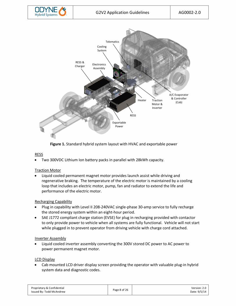
Figure 1. Standard hybrid system layout with HVAC and exportable power
RESS • Two 300VDC Lithium Ion battery packs in parallel with 28kWh capacity. Traction Motor • Liquid cooled permanent magnet motor provides launch assist while driving and
regenerative braking. The temperature of the electric motor is maintained by a cooling loop that includes an electric motor, pump, fan and radiator to extend the life and performance of the electric motor.
Recharging Capability • Plug in capability with Level II 208-240VAC single-phase 30-amp service to fully recharge
the stored energy system within an eight-hour period. • SAE J1772 compliant charge station (EVSE) for plug in recharging provided with contactor
to only provide power to vehicle when all systems are fully functional. Vehicle will not start while plugged in to prevent operator from driving vehicle with charge cord attached.
Inverter Assembly • Liquid cooled inverter assembly converting the 300V stored DC power to AC power to
power permanent magnet motor. LCD Display • Cab mounted LCD driver display screen providing the operator with valuable plug-in hybrid
system data and diagnostic codes.
RESS & Charger
Cooling System
RESS
A/C Evaporator & Controller
(Cab)
Electronics Assembly
Exportable Power
Traction Motor & Inverter
Telematics
Heater
G2V2 Application Guidelines AG0002-2.0
Proprietary & Confidential Issued By: Todd McAndrew Page 9 of 26 Version: 2.0
Date: 9/5/14
Auxiliary Heating and Air Conditioning System • Auxiliary cab heating and air conditioning system for use during all electric ePTO mode
while the engine is not running. Exportable Power • Odyne provides and installs a frame-mounted inverter assembly capable of providing 6kW
of pure sine 120/240VAC wave power. Inverter is powered from the 300VDC battery system. o A pigtail is provided for FSM integration. o A distribution panel/breaker box is recommended (FSM provided). o Electrical outlets and wiring are to be provided by the FSM.
• Exportable power can be activated while driving or during ePTO mode. o NOTE: If exportable power is required during plug-in charging, 12V outlets or a 12V
inverter should be considered (FSM provided). • If less than 2kW of power is required, Odyne recommends a 12VDC inverter (FSM
provided). o FSM must ensure chassis alternator and battery system are sized to accommodate the
12VDC inverter.

G2V2 Application Guidelines AG0002-2.0
Proprietary & Confidential Issued By: Todd McAndrew Page 10 of 26 Version: 2.0
Date: 9/5/14
SECTION 2: ENGINEERING
G2V2 Application Guidelines AG0002-2.0
Proprietary & Confidential Issued By: Todd McAndrew Page 11 of 26 Version: 2.0
Date: 9/5/14
2. ENGINEERING
2.1. System Specifications
Weight • Based on standard configuration, all options
System Weight = 1,900 lbs. • Consult Odyne for assistance
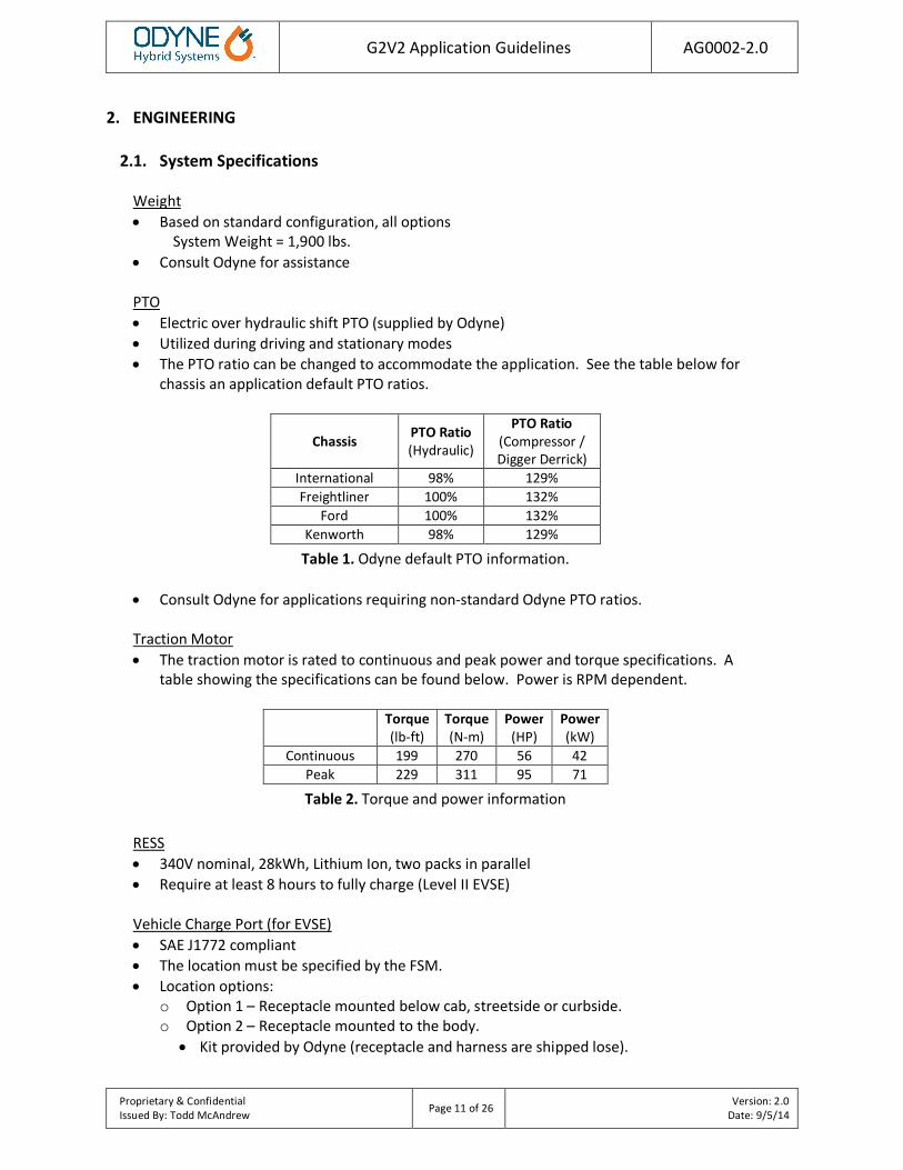
PTO • Electric over hydraulic shift PTO (supplied by Odyne) • Utilized during driving and stationary modes • The PTO ratio can be changed to accommodate the application. See the table below for
chassis an application default PTO ratios.
Chassis PTO Ratio (Hydraulic)
PTO Ratio (Compressor / Digger Derrick)
International 98% 129% Freightliner 100% 132%
Ford 100% 132% Kenworth 98% 129%
Table 1. Odyne default PTO information.
• Consult Odyne for applications requiring non-standard Odyne PTO ratios.
Traction Motor • The traction motor is rated to continuous and peak power and torque specifications. A
table showing the specifications can be found below. Power is RPM dependent.
Torque (lb-ft)
Torque (N-m)
Power (HP)
Power (kW)
Continuous 199 270 56 42 Peak 229 311 95 71
Table 2. Torque and power information
RESS • 340V nominal, 28kWh, Lithium Ion, two packs in parallel • Require at least 8 hours to fully charge (Level II EVSE)
Vehicle Charge Port (for EVSE) • SAE J1772 compliant • The location must be specified by the FSM. • Location options:
o Option 1 – Receptacle mounted below cab, streetside or curbside. o Option 2 – Receptacle mounted to the body.
• Kit provided by Odyne (receptacle and harness are shipped lose).

G2V2 Application Guidelines AG0002-2.0
Proprietary & Confidential Issued By: Todd McAndrew Page 12 of 26 Version: 2.0
Date: 9/5/14
• FSM is responsible for the location and installation; ensure it has proper orientation and clearance (See receptacle cutout below for size and orientation.).
J1772 Receptacle Cutout
Operator Display • Used to display important information and faults, independent of OEM chassis display. • Size: 3.00” long x 3.00” wide x 0.83” deep
Operator Display
Operator Switches • Used to control the various functions of the system, independent of OEM chassis switches.
o ePTO o Launch/Regen Disable o A/C (if equipped) o Heat (if equipped) o Exportable Power (if equipped) o Air Compressor (if equipped)
• Size: 4.53” long x 2.40” high x 1.44” deep • Located on the center dash or overhead console (chassis dependent)
Operator Switch Pack

G2V2 Application Guidelines AG0002-2.0
Proprietary & Confidential Issued By: Todd McAndrew Page 13 of 26 Version: 2.0
Date: 9/5/14
DC/DC Converter • Provides power from RESS to 12V chassis batteries during ePTO in lieu of the chassis
alternator. • Capable of 2.2kW (13.7V / 160A) continuous • FSM must consider engine off worksite loads.
EVSE Requirements • SAE J1772 compliant • Level II: 208-240VAC, 30A, single phase • Level I: 110-120VAC, 15A • Contact EVSE manufacturer for installation information. • Consult Odyne for recommendations.
2.2. System Options
Exportable Power • 6,000W (120VAC, 40A or 240VAC, 20A) • A 25 ft. pigtail harness is provided for FSM integration (Figure 2). • Distribution panel/breaker box is recommended for FSM integration • Provides power during ePTO mode and driving modes only.
o Note: Does not operate during plug-in charging. • Consult Odyne for assistance.
Signal Wire Gauge Wire Color N1 10 White L1 10 Black N2 10 Black/White L2 10 Red
GND 10 Green
Figure 2. FSM exportable power harness
Auxiliary Heat • 17,100BTU/hr heating system to provide heat inside the cab • Integrated into the engine glycol cooling system.

G2V2 Application Guidelines AG0002-2.0
Proprietary & Confidential Issued By: Todd McAndrew Page 14 of 26 Version: 2.0
Date: 9/5/14
• Uses the existing dash climate controls. • Tied into the existing chassis fuel tank. • Designed to maintain temperature during ePTO mode. • Consult Odyne for assistance. Auxiliary Air Conditioning • 15,000BTU/hr A/C system provides cooling inside the cab. • Independent from cab A/C system. • The evaporator/blower assembly mounts inside a standard cab between the seats or
underneath the bench seat in extended and crew cabs. • Designed to maintain temperature during ePTO mode. • Consult Odyne for assistance. Telematics System • Used to track vehicle location via GPS and monitor important vehicle/hybrid parameters. • Telematics controller is located below the cab or back of the cab (chassis dependent). • Telematics antenna must be relocated to a bracket by the FSM near the roof level.
Antenna must have a clear line of sight. o Antenna size: 4” x 4” x 3” high o Antenna cable length: 18 ft.
• Consult Odyne for assistance.
2.3 System Dimensions and Clearances
Standard Configuration
Figure 3. International 4300 4 x 2

G2V2 Application Guidelines AG0002-2.0
Proprietary & Confidential Issued By: Todd McAndrew Page 15 of 26 Version: 2.0
Date: 9/5/14
The example layout in Figure 3 is for reference only. It is used to show standard locations. Odyne will provide layout drawings/models for each chassis.
Chassis Dimensions • Minimum CA = 108”; CT = 136” • CA lengths less than 108” may be considered on a case by case basis. • Consult Odyne for assistance.
RESS • Standard battery pack assembly location is 32" from the center of the rear axle; battery
pack assembly will be located a minimum of 2" forward of the spring shackle. o Battery packs may move forward to avoid interference with cross member
hardware (Figures 4 and 5). NOTE: Due to frequent interference with cross members on Freightliner M2 106 chassis, the battery packs are commonly located 4-10” from the spring shackle. Consult Odyne for assistance with actual location.
• RESS assemblies will not extend above the top of the frame rails. • Areas shown in green below (Figures 4 and 5) represent installation clearance required for
hybrid wiring harnesses and cooling hoses. • FSM must provide a minimum of 1” body clearance around RESS bracket assembly.
o Battery packs require at least 1” of clearance above the brackets for removal.
Figure 4. Street Side RESS (Non-standard location)
G2V2 Application Guidelines AG0002-2.0
Proprietary & Confidential Issued By: Todd McAndrew Page 16 of 26 Version: 2.0
Date: 9/5/14
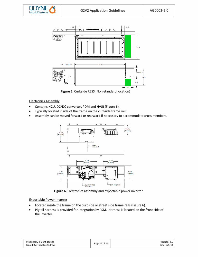
Figure 5. Curbside RESS (Non-standard location)
Electronics Assembly • Contains HCU, DC/DC converter, PDM and HVJB (Figure 6). • Typically located inside of the frame on the curbside frame rail. • Assembly can be moved forward or rearward if necessary to accommodate cross members.
Figure 6. Electronics assembly and exportable power inverter
Exportable Power Inverter • Located inside the frame on the curbside or street side frame rails (Figure 6). • Pigtail harness is provided for integration by FSM. Harness is located on the front side of
the inverter.
G2V2 Application Guidelines AG0002-2.0
Proprietary & Confidential Issued By: Todd McAndrew Page 17 of 26 Version: 2.0
Date: 9/5/14
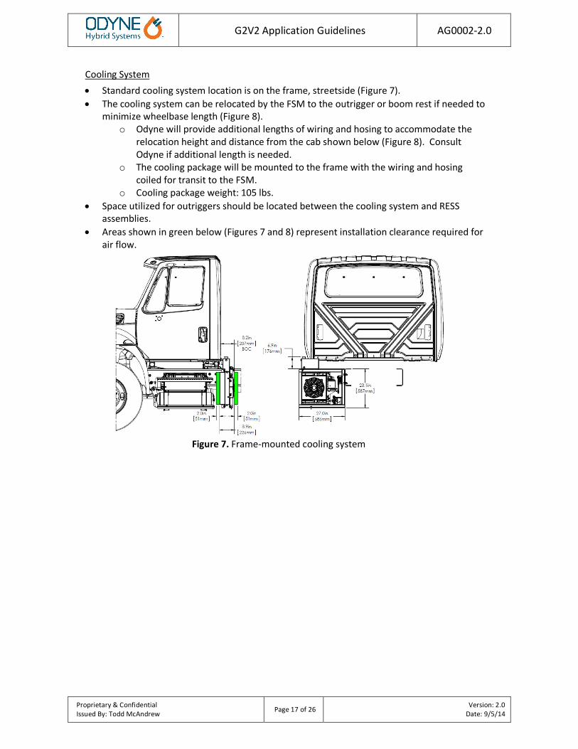
Cooling System • Standard cooling system location is on the frame, streetside (Figure 7). • The cooling system can be relocated by the FSM to the outrigger or boom rest if needed to
minimize wheelbase length (Figure 8). o Odyne will provide additional lengths of wiring and hosing to accommodate the
relocation height and distance from the cab shown below (Figure 8). Consult Odyne if additional length is needed.
o The cooling package will be mounted to the frame with the wiring and hosing coiled for transit to the FSM.
o Cooling package weight: 105 lbs. • Space utilized for outriggers should be located between the cooling system and RESS
assemblies. • Areas shown in green below (Figures 7 and 8) represent installation clearance required for
air flow.
Figure 7. Frame-mounted cooling system
G2V2 Application Guidelines AG0002-2.0
Proprietary & Confidential Issued By: Todd McAndrew Page 18 of 26 Version: 2.0
Date: 9/5/14
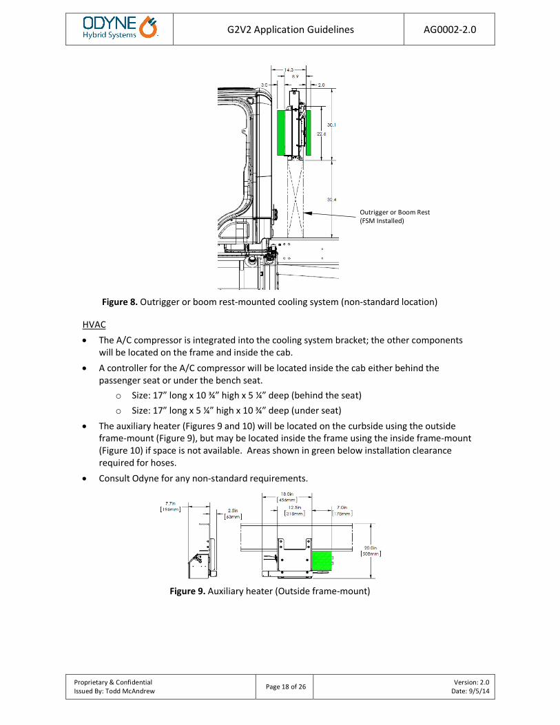
Figure 8. Outrigger or boom rest-mounted cooling system (non-standard location)
HVAC • The A/C compressor is integrated into the cooling system bracket; the other components
will be located on the frame and inside the cab. • A controller for the A/C compressor will be located inside the cab either behind the
passenger seat or under the bench seat. o Size: 17” long x 10 ¾” high x 5 ¼” deep (behind the seat) o Size: 17” long x 5 ¼” high x 10 ¾” deep (under seat)
• The auxiliary heater (Figures 9 and 10) will be located on the curbside using the outside frame-mount (Figure 9), but may be located inside the frame using the inside frame-mount (Figure 10) if space is not available. Areas shown in green below installation clearance required for hoses.
• Consult Odyne for any non-standard requirements.
Figure 9. Auxiliary heater (Outside frame-mount)
Outrigger or Boom Rest (FSM Installed)

G2V2 Application Guidelines AG0002-2.0
Proprietary & Confidential Issued By: Todd McAndrew Page 19 of 26 Version: 2.0
Date: 9/5/14
Figure 10. Auxiliary heater (Inside frame-mount)
Miscellaneous • Items not shown in above configuration:
o Operator Display – mounted inside cab o A/C evaporator and controller – mounted inside cab o Telematics – typically mounted under cab, streetside o Wire harness (low & high voltage) o Plumbing for cooling loop
2.4 FSM Integration Information
Traction Motor and PTO • The traction motor will be set to operate at the same speed(s) as the hydraulic pump/air
compressor in ePTO mode, as specified by the FSM. • The motor is continuously coupled to the transmission via the PTO while driving (so it will
be at the same RPM as the engine). • The PTO will be disengaged if/when the maximum RPM rating has been reached to prevent
damage (2,600RPM). • Other configurations must be approved by Odyne.
Body and Equipment • The body must account for the location of the vehicle charge port (if applicable). • The body must account for the RESS assemblies, cooling system, A/C and heater assemblies
to allow proper clearance in the body and sub-frame • Body compartments may wrap around RESS assemblies and do not require clearance to
slide in/out. Ensure at least 1” of clearance around RESS bracket assemblies. • The equipment must account for the motor/inverter and electronics assemblies during the
layout of any additional equipment, hose or wiring. • Consult Odyne for assistance. Miscellaneous • The optional HVAC features will only operate while in ePTO mode. • Odyne splices into the ignition circuit to shut down the power to the ECM and TCU. The
FSM must ensure the proper ignition power is used. • It is important to limit the quantity of loads on the 12V chassis batteries, if not; the drain
on the chassis batteries may prevent the engine from starting and/or cause damage. • If an Emergency shutdown button is required to stop hydraulic or pneumatic operation
then a circuit should be added to disable (turn off) the demand request and the pump bypass or clutch control; not provided by Odyne.

G2V2 Application Guidelines AG0002-2.0
Proprietary & Confidential Issued By: Todd McAndrew Page 20 of 26 Version: 2.0
Date: 9/5/14
• Consult Odyne for assistance.
ECM / RPM control • Custom programming to the chassis ECM is needed to control engine speeds for operating
the truck mounted equipment, it must match the hybrid system motor speeds. o NOTE: A remote engine PTO programming port is required. This port must be
located under the hood near the firewall. • RPM during ePTO operation is configurable in 25 RPM increments. • Three speeds are utilized: idle bump up, low and high • In ePTO mode the engine and motor will only operate in low or high depending on the
application • If the hybrid system is disabled then the engine will use all three speeds and operate as a
demand throttle with 2 speeds (ramp up from idle bump up to either low or high as needed) depending on the application.
• Other configurations must be approved by Odyne.
** It is important to note that if the chassis goes in for service to a chassis dealer and needs to have the ECM reprogrammed or replaced, the dealer needs to save Odyne's custom programming and add it to the new or updated ECM. Failure to do so may result in the vehicle not operating properly in hybrid mode. **
2.5 Hydraulic Application
Pump Selection • The FSM must specify required operating speed(s), conditions, performance, pump flange
and shaft configuration. A bell housing/pump mount and couplers are added to the output of the motor to accommodate a variety of pump mounting requirements.
o NOTE: Odyne requires a splined pump shaft, sized to accommodate the hydraulic load.
• The pump must have load sense and pressure compensation features (bypass solenoid) to avoid damage to the hydraulic system while driving. o Eaton P/N: X630AA00459A (Recommended if using Eaton pump listed below.)
• Eaton is the recommended pump manufacturer o 420 Series, Model Code
• The pump must have a maximum RPM rated greater than or equal the maximum RPM rating on the PTO to prevent damage (2600RPM).
• If a tandem pump is required it should be properly supported.
Integration • The demand signal must be tied into all the controls to indicate when a function is being
requested, typically directly controlled by the operator. • Default set speeds: idle bump up = 750 (engine), low = 800 (engine & motor), high = 1200 • Odyne recommends a hydraulic pump speed of at least 800 rpm. • Consult Odyne for assistance with selection and installation.

G2V2 Application Guidelines AG0002-2.0
Proprietary & Confidential Issued By: Todd McAndrew Page 21 of 26 Version: 2.0
Date: 9/5/14
Setup and Operation • In the initial setup of the hydraulic system it is recommended that the hybrid system be
disabled until the hydraulic system has been tested.
2.6 Pneumatic Application
System Configuration and Operation • A switch on the Odyne operator switch pack is provided to enable the operation of the air
compressor. • This application does not require the bell housing. Odyne provides a companion flange on
the backside of the traction motor for a drive shaft connection to the clutch. Please ensure the shaft angle does not exceed supplier guidelines.
• The demand signal must be tied into the compressor system to indicate when air is being requested, typically indirectly controlled by the operator. o An air reservoir (20-30 gallons) with a pressure switch is required for use as a demand
signal to activate the hybrid system.
2.7 Electrical Interface
FSM connector • Odyne provides an FSM connector (Figure 11) for interfacing with the Odyne system that is
located inside the street side frame rail, back of cab. A list of signals and corresponding pin numbers can be found below (Table 3).
Table 3. FSM connector, J26
Pin Signal Min Max Units Notes 1 5V Sensor V+ 4.9 5.1 V 5V Power, 100mA Max 2 5V Sensor Ground 0 0.1 A Sensor Isolated GND 3 Pneumatic Compressor Temperature 0 33.65K Ω *Thermistor Input
4 Hydraulic Pressure Sensor / Pneumatic Receiver 0 5.1 V Sensor Input
5 Pneumatic Reservoir Pressure Sensor 0 5.1 V Sensor Input 6 Hydraulic / Pneumatic Flow Sensor 0 5.1 V Sensor Input 7 Pneumatic Fan Relay 0 1 A Low Side Output 8 Chassis Ground 0 20 A Vbat Ground 9 High Speed Request 0 16 V **Toggle Input
10 N/C N/C N/C N/C N/C 11 Hydraulic Pressure Demand Request 0 16 V **Toggle Input 12 N/C N/C N/C N/C N/C 13 Auxiliary Coil Driver 0 0.75 A Low Side Output 14 N/C N/C N/C N/C N/C 15 N/C N/C N/C N/C N/C 16 N/C N/C N/C N/C N/C 17 N/C N/C N/C N/C N/C 18 FSM ePTO Contact 9 16 V Switched Vbat Power
19 Hydraulic Enable Solenoid / Pneumatic Clutch 9 16 V High Side Output, 5A
Max

G2V2 Application Guidelines AG0002-2.0
Proprietary & Confidential Issued By: Todd McAndrew Page 22 of 26 Version: 2.0
Date: 9/5/14
*Thermistor Characteristics 3KΩ @ 25°C, 100.95KΩ @ -40°C, 55.8Ω @ 150°C **All Toggle inputs are analog inputs used for digital (on/off) signal. It is recommended that low level inputs remain at a voltage level <0.8V. Voltages higher than 6V will result in a positive input reading. No damage will occur for input voltages up to 16V. Pins that are typically utilized by the FSM are in bold.
Figure 11. Deutsch HDP26-24-19SN
(Mating connector required from Final Stage Manufacturer: Deutsch HDP24-24-19PN)
G2V2 Application Guidelines AG0002-2.0
Proprietary & Confidential Issued By: Todd McAndrew Page 23 of 26 Version: 2.0
Date: 9/5/14
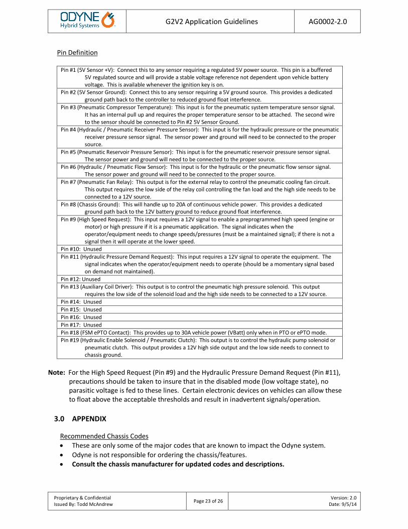
Pin Definition
Pin #1 (5V Sensor +V): Connect this to any sensor requiring a regulated 5V power source. This pin is a buffered 5V regulated source and will provide a stable voltage reference not dependent upon vehicle battery voltage. This is available whenever the ignition key is on.
Pin #2 (5V Sensor Ground): Connect this to any sensor requiring a 5V ground source. This provides a dedicated ground path back to the controller to reduced ground float interference.
Pin #3 (Pneumatic Compressor Temperature): This input is for the pneumatic system temperature sensor signal. It has an internal pull up and requires the proper temperature sensor to be attached. The second wire to the sensor should be connected to Pin #2 5V Sensor Ground.
Pin #4 (Hydraulic / Pneumatic Receiver Pressure Sensor): This input is for the hydraulic pressure or the pneumatic receiver pressure sensor signal. The sensor power and ground will need to be connected to the proper source.
Pin #5 (Pneumatic Reservoir Pressure Sensor): This input is for the pneumatic reservoir pressure sensor signal. The sensor power and ground will need to be connected to the proper source.
Pin #6 (Hydraulic / Pneumatic Flow Sensor): This input is for the hydraulic or the pneumatic flow sensor signal. The sensor power and ground will need to be connected to the proper source.
Pin #7 (Pneumatic Fan Relay): This output is for the external relay to control the pneumatic cooling fan circuit. This output requires the low side of the relay coil controlling the fan load and the high side needs to be connected to a 12V source.
Pin #8 (Chassis Ground): This will handle up to 20A of continuous vehicle power. This provides a dedicated ground path back to the 12V battery ground to reduce ground float interference.
Pin #9 (High Speed Request): This input requires a 12V signal to enable a preprogrammed high speed (engine or motor) or high pressure if it is a pneumatic application. The signal indicates when the operator/equipment needs to change speeds/pressures (must be a maintained signal); if there is not a signal then it will operate at the lower speed.
Pin #10: Unused Pin #11 (Hydraulic Pressure Demand Request): This input requires a 12V signal to operate the equipment. The
signal indicates when the operator/equipment needs to operate (should be a momentary signal based on demand not maintained).
Pin #12: Unused Pin #13 (Auxiliary Coil Driver): This output is to control the pneumatic high pressure solenoid. This output
requires the low side of the solenoid load and the high side needs to be connected to a 12V source. Pin #14: Unused Pin #15: Unused Pin #16: Unused Pin #17: Unused Pin #18 (FSM ePTO Contact): This provides up to 30A vehicle power (VBatt) only when in PTO or ePTO mode. Pin #19 (Hydraulic Enable Solenoid / Pneumatic Clutch): This output is to control the hydraulic pump solenoid or
pneumatic clutch. This output provides a 12V high side output and the low side needs to connect to chassis ground.
Note: For the High Speed Request (Pin #9) and the Hydraulic Pressure Demand Request (Pin #11),
precautions should be taken to insure that in the disabled mode (low voltage state), no parasitic voltage is fed to these lines. Certain electronic devices on vehicles can allow these to float above the acceptable thresholds and result in inadvertent signals/operation.
3.0 APPENDIX
Recommended Chassis Codes • These are only some of the major codes that are known to impact the Odyne system. • Odyne is not responsible for ordering the chassis/features. • Consult the chassis manufacturer for updated codes and descriptions.

G2V2 Application Guidelines AG0002-2.0
Proprietary & Confidential Issued By: Todd McAndrew Page 24 of 26 Version: 2.0
Date: 9/5/14
International DuraStar 4300/4400
Standard Cab Extended Cab Crew Cab
Transmission Allison 3000/3500 RDS
Allison Spare Input/Output (13WUC)
Engine Remote Engine Control (12VZA)
Exhaust Vertical Tailpipe (7BHT) Vertical Tailpipe (7BEJ) Vertical Tailpipe (7BHU)
Battery Box LH Side Under Cab
Fuel Tank 50 Gal RH Side Under Cab (15SNY;15SNZ)
Air Dryer Forward of Front Wheel (4VGA) Wheelbase &
Frame CA: 102”+ (Vertical Exhaust)
International WorkStar 7300/7400/7500
Standard Cab Extended Cab Crew Cab
Transmission Allison 3000/3500 RDS
Allison Spare Input/Output (13WUC) Engine Remote Engine Control (12VZA)
Exhaust Vertical Tailpipe (7BHT;7BEJ)
Vertical Tailpipe (7BEJ)
Vertical Tailpipe (7BHU)
Battery Box LH Side Under Cab; RH Side Under Cab (8WGG)
Fuel Tank 50 Gal RH Side Under Cab (15SNY;15SNZ)
Air Tank 4VDX (Required with LH fuel tank and 8WGG) Wheelbase &
Frame CA: 108”+ (Vertical Exhaust)
Ford F-750
Regular Cab Super Cab Crew Cab Transmission Allison 3000/3500 RDS
Allison Programming I/O RDS (94B) Exhaust RH Under Cab DPF & SCR; RH Vertical Outlet (91D)
Battery Box Temporary Mounted (63G) Fuel Tank 50 Gal LH rail under cab (982) DEF Tank 5 Gal LH rail under cab (86K)
Wheelbase & Frame CA: 108”+ (Vertical Exhaust)

G2V2 Application Guidelines AG0002-2.0
Proprietary & Confidential Issued By: Todd McAndrew Page 25 of 26 Version: 2.0
Date: 9/5/14
Kenworth T370
Standard Cab Extended Cab Crew Cab
Transmission Allison 3000/3500 RDS N/A N/A
Allison Auto neutral N/A N/A
Exhaust R/H Vertical R/H Under Cab DPF/SCR N/A N/A
Battery Box In Cab or Temp Frame Mount N/A N/A
Fuel Tank Rectangular L/H Under Cab N/A N/A DEF Tank Small L/H Under Cab N/A N/A
Wheelbase & Frame CA: 108”+ (Vertical Exhaust)
Freightliner M2
Day Cab Extended Cab Crew Cab
Transmission Allison 3000/3500 RDS
Allison Allison Package 223 (or equivalent)
Exhaust RH Side Vertical (016-1C2) RH Side Vertical (016-1DE)
Battery Box LH Side Under Cab (282-001) – Two Battery (All Three-Battery Boxes Require Relocation)
Fuel Tank 50 Gal LH Side Under Cab (204-215) Auxiliary Fuel Supply and Return Ports (20E-004)
DEF Tank 6 Gal LH Rail Under Cab (43X-002) 6 Gal LH Rail Under Cab (43X-005)
Air Tank
Clear Frame Rail From BOC to FT RR Susp Brkt, RH Rail Outboard (607-018)
Steel Air Brake Reservoirs, No Triple or Torpedo Tanks (460-090)
Air Dryer Air Dryer Mounted Under Hood (479-012) Instrumentation &
Controls Engine Remote Interface Connector in Engine Compartment (163-004)
Wheelbase & Frame CA: 110.45”+ (Vertical Exhaust & Under Hood Air Dryer)

G2V2 Application Guidelines AG0002-2.0
Proprietary & Confidential Issued By: Todd McAndrew Page 26 of 26 Version: 2.0
Date: 9/5/14
4.0 REVISION LOG
• The information in the description column must clearly identify the major changes to each revision.
Date Description Revision Level
Revised By
2/3/2014 Initial document release 1.0 TAM 9/5/2014 RESS bracket, cooling package height and other
system updates 2.0 TAM