g1000 simulator tutorial - moaastpetearea.com grid tutorial g1000 flight plan...1 g1000 simulator...
TRANSCRIPT

1
G1000 SIMULATOR TUTORIAL
FOR
MISSION OBSERVERS
AND
CO-PILOTS
FOR A
PARALLEL GRID SEARCH
MIAMI 4D
USING
CROSS TRACK FLIGHT PLAN METHOD
South of Lakeland Airport Florida (KLAL)
Start Southwest Corner
East-West Tracks

2
The simulated aircraft can be anywhere, and is shown at Marco IslandAirport (MKY), FL.
Move the simulated aircraft to Lakeland Airport (KLAL), FL. Press the ENTER key twice toget the DEMO MODE page. If necessary, use the outer FMS knob to highlight WAYPOINT.

3
GENERATE WAYPOINTS P1, P2, P3, & P4:P1 = N 27 deg 45.0 min W 082 deg 07.5 minP2 = N 27 deg 45.0 min W 082 deg 00.0 minP3 = N 27 deg 52.5 min W 082 deg 00.0 minP4 = N 27 deg 52.5 min W 082 deg 07.5 min
NOTE:
When entering waypoints into the REFERENCE WAYPOINT field, first turn theinner FMS knob one click clockwise before turning this knob counter clockwise.If the inner FMS knob is first turned counter clockwise it will produce a dropdown menu that you will need to clear this menu by pressing the CLR key.
Use the outer FMS knob to move to the WPT pages. Then use the inner FMS knob tomove to WPT page 5 (WPT – USER WPT INFORMATION).

4
Press the NEW soft key to enter a new USER waypoint.
Using the inner and the outer FMS knobs enter G1 as a USER waypoint. This waypoint isthe Commence Search Point and the Southwest corner of Miami Grid 4D.

5
Press the ENTER key to accept G1 as a new USER waypoint.
Turn the Outer Knob one click counter-clockwise to highlight the Lat-Long field.

6
Turn the Inner FMS Knob one click clockwise to highlight only the “N’.
Use the Inner and the Outer FMS Knobs to set the Latitude to 27 deg 45.0 min and theLongitude to 082 deg 07.5 min.

7
Press the ENTER key to accept the Latitude and Longitude settings for G1
Press the NEW soft key to enter a new USER waypoint.

8
Using the inner and the outer FMS knobs enter G2 as a USER waypoint. This waypoint isthe Southeast corner of Miami Grid 4D.
Press the ENTER key to accept G2 as a new USER waypoint.

9
Turn the Outer Knob one click counter-clockwise to highlight the Lat-Long field.
Use the Inner and the Outer FMS Knobs to set the Latitude to 27 deg 45.0 min and theLongitude to 082 deg 00.0 min.

10
Press the ENTER key to accept the Latitude and Longitude settings for G2
Press the NEW soft key to enter a new USER waypoint.

11
Using the inner and the outer FMS knobs enter G3 as a USER waypoint. This waypoint isthe Northeast corner of Miami Grid 4D.
Press the ENTER key to accept G3 as a new USER waypoint.

12
Turn the Outer Knob one click counter-clockwise to highlight the Lat-Long field.
Turn the Inner FMS Knob one click clockwise to highlight only the “N’.

13
Use the Inner and the Outer FMS Knobs to set the Latitude to 27 deg 52.5 min and theLongitude to 082 deg 00.0 min.
Press the ENTER key to accept the Latitude and Longitude settings for G3

14
Press the NEW soft key to enter a new USER waypoint.
Using the inner and the outer FMS knobs enter G4 as a USER waypoint. This waypoint isthe Northwest corner of Miami Grid 4D.
15
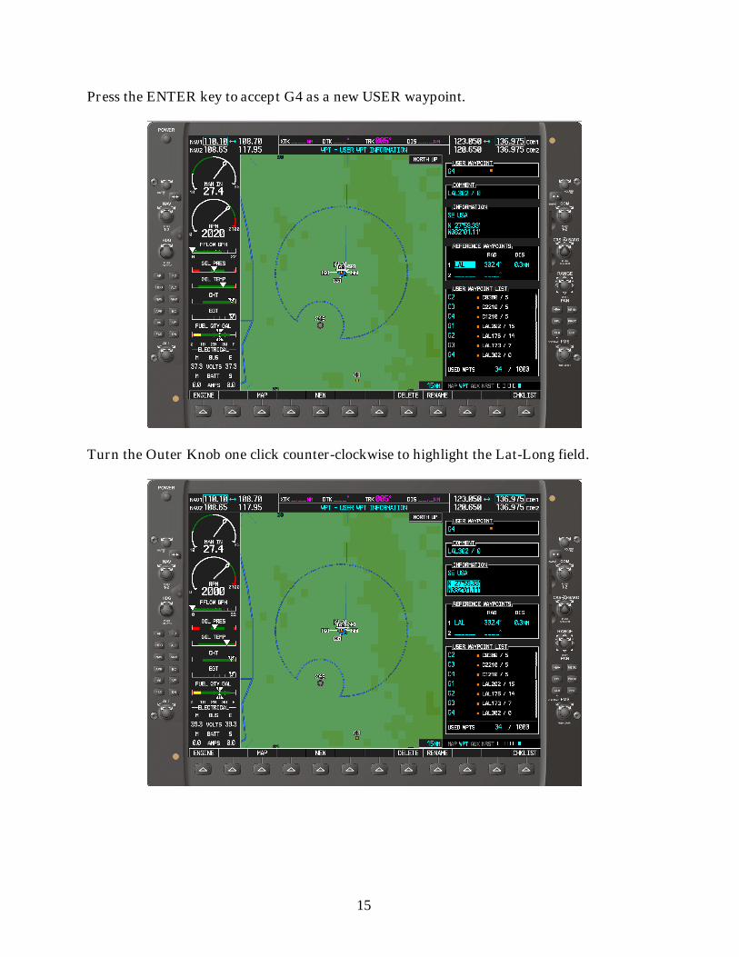
Press the ENTER key to accept G4 as a new USER waypoint.
Turn the Outer Knob one click counter-clockwise to highlight the Lat-Long field.

16
Turn the Inner FMS Knob one click clockwise to highlight only the “N’.
Use the Inner and the Outer FMS Knobs to set the Latitude to 27 deg 52.5 min and theLongitude to 082 deg 07.5 min.

17
Press the ENTER key to accept the Latitude and Longitude settings for G4

18
Press in the inner FMS knob to remove the cursor. Then turn the outer FMS knobcounter clockwise to return to the MAP page. For the real airplane press the CLR keyuntil MAP home page appears.
Click on the range knob to increase the range to 30 nm to see if the layout of the newlygenerated USER waypoints looks correct. You will not see waypoints 1 and 2 on yourcomputer. These are waypoints the author added at an earlier time.
NOW WE NEED TO BUILD THE FLIGHT PLAN:
G2 > G3 > G4 > G1 > G2
NOTE:
When entering waypoints into the flight plan first turn the inner FMS knob oneclick clockwise before turning counter clockwise. If the inner FMS knob is firstturned counter clockwise it will produce a drop down menu that you will need topress the CLR key to get rid of this menu.

19
Press the FPL key to bring up the flight plan page:
Press the inner FMS knob to bring up the cursor.
20
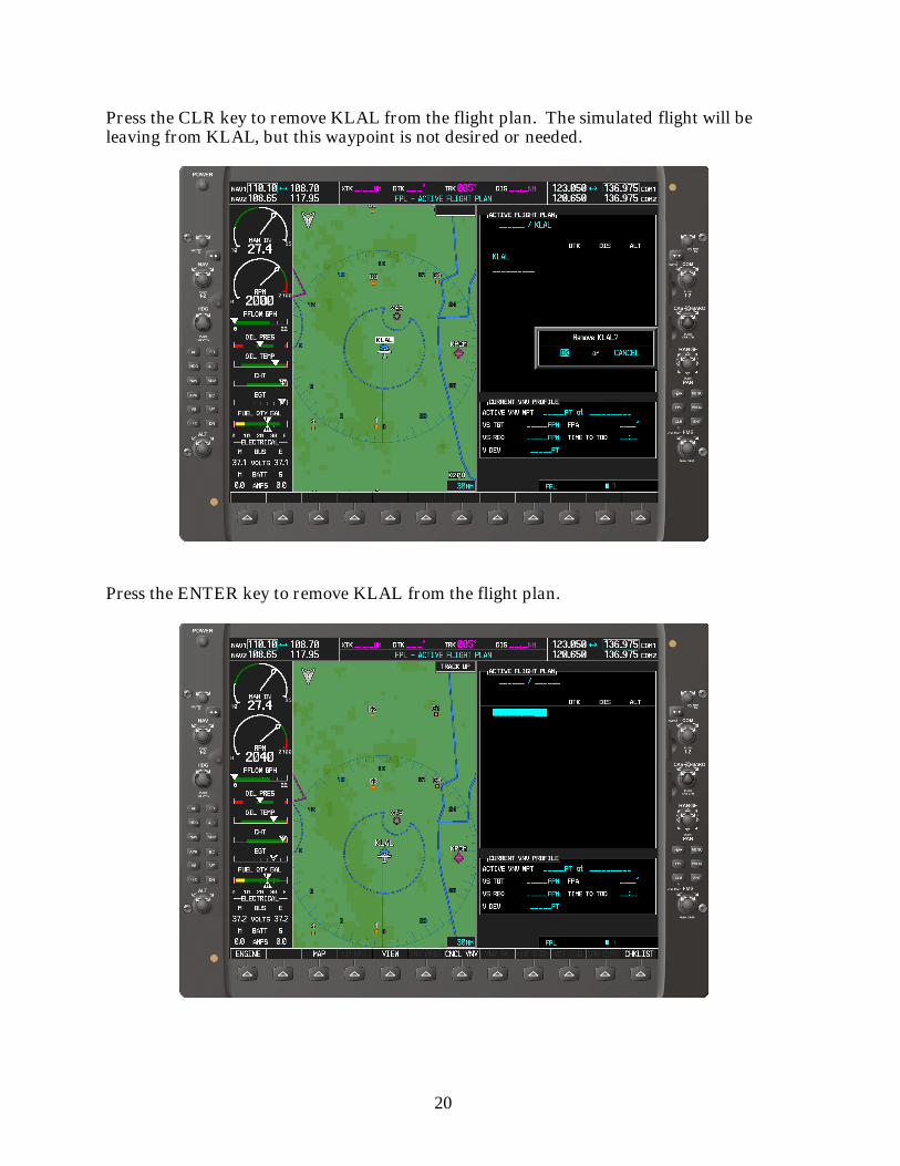
Press the CLR key to remove KLAL from the flight plan. The simulated flight will beleaving from KLAL, but this waypoint is not desired or needed.
Press the ENTER key to remove KLAL from the flight plan.
21
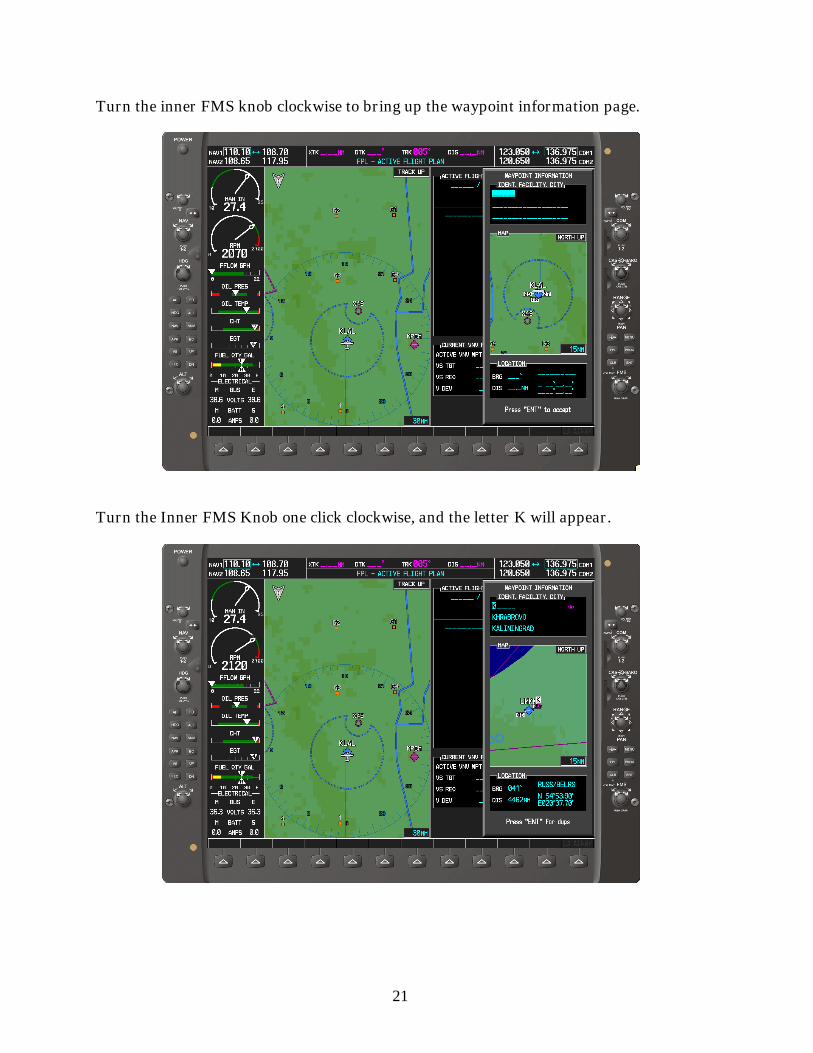
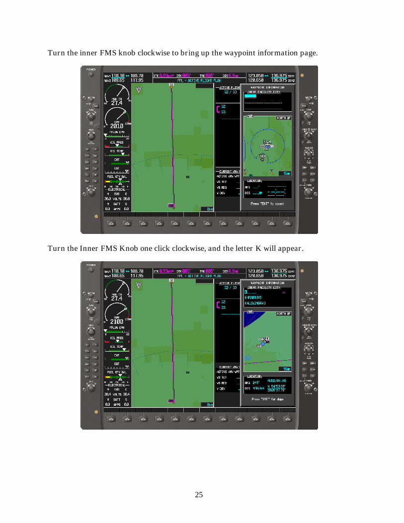
Turn the inner FMS knob clockwise to bring up the waypoint information page.
Turn the Inner FMS Knob one click clockwise, and the letter K will appear.
22
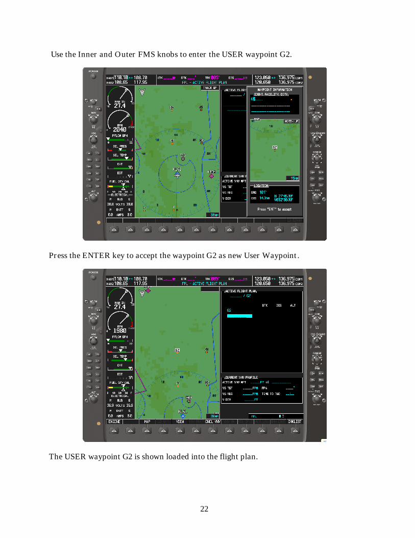
Use the Inner and Outer FMS knobs to enter the USER waypoint G2.
Press the ENTER key to accept the waypoint G2 as new User Waypoint.
The USER waypoint G2 is shown loaded into the flight plan.

23
Turn the inner FMS knob clockwise to bring up the waypoint information page.
Turn the Inner FMS Knob one click clockwise, and the letter K will appear.

24
Use the Inner and Outer FMS knobs to enter the USER waypoint G3.
Press the ENTER key to accept the waypoint G3 as new User Waypoint.
The USER waypoint G3 is shown loaded into the flight plan.
25
Turn the inner FMS knob clockwise to bring up the waypoint information page.
Turn the Inner FMS Knob one click clockwise, and the letter K will appear.

26
Use the Inner and Outer FMS knobs to enter the USER waypoint G4.
Press the ENTER key to accept the waypoint G4 as new User Waypoint.
The USER waypoint G4 is shown loaded into the flight plan.

27
Turn the inner FMS knob clockwise to bring up the waypoint information page.
Turn the Inner FMS Knob one click clockwise, and the letter K will appear.

28
Use the Inner and Outer FMS knobs to enter the USER waypoint G1.
Press the ENTER key to accept the waypoint G1 as new User Waypoint.
The USER waypoint G1 is shown loaded into the flight plan.

29
Turn the inner FMS knob clockwise to bring up the waypoint information page.
Turn the Inner FMS Knob one click clockwise, and the letter K will appear.

30
Use the Inner and Outer FMS knobs to enter the USER waypoint G2.
Press the ENTER key to accept the waypoint G2 as new User Waypoint.
The second USER waypoint G2 is shown loaded into the flight plan.

31
Use the Outer FMS Knob to high light the G1 waypoint.
Press the DIRECT-TO key.

32
Press the ENTER Key to accept G1 as the direct-to waypoint.
Press the ENTER Key again to load G1 as the direct-to waypoint.
33
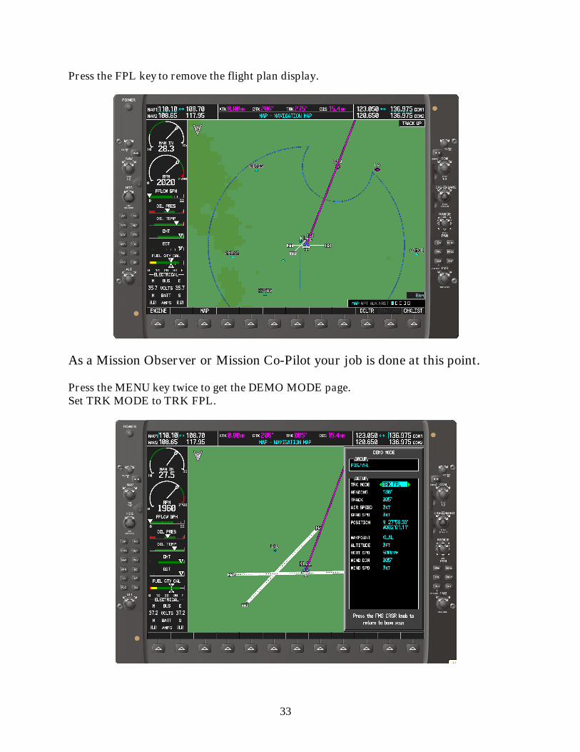
Press the FPL key to remove the flight plan display.
As a Mission Observer or Mission Co-Pilot your job is done at this point.
Press the MENU key twice to get the DEMO MODE page.Set TRK MODE to TRK FPL.

34
Move the cursor down to AIR SPEED using the Outer FMS Knob.
Using the Inner FMS knob change the AIR SPEED to 100 KT.
35
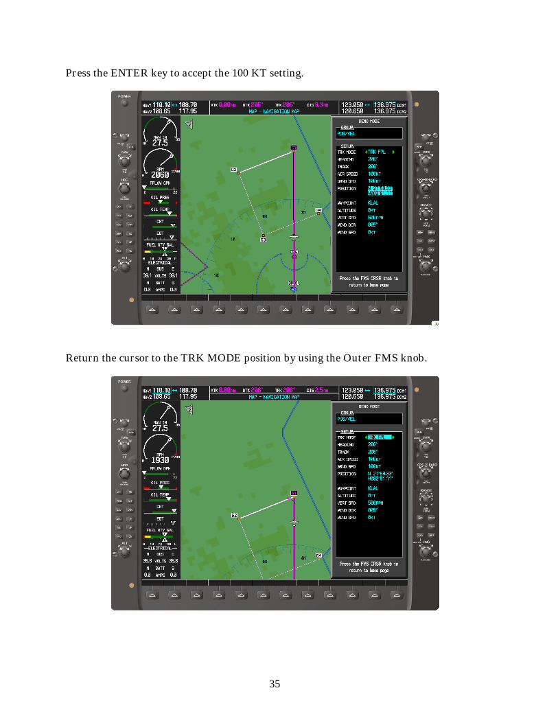
Press the ENTER key to accept the 100 KT setting.
Return the cursor to the TRK MODE position by using the Outer FMS knob.
36
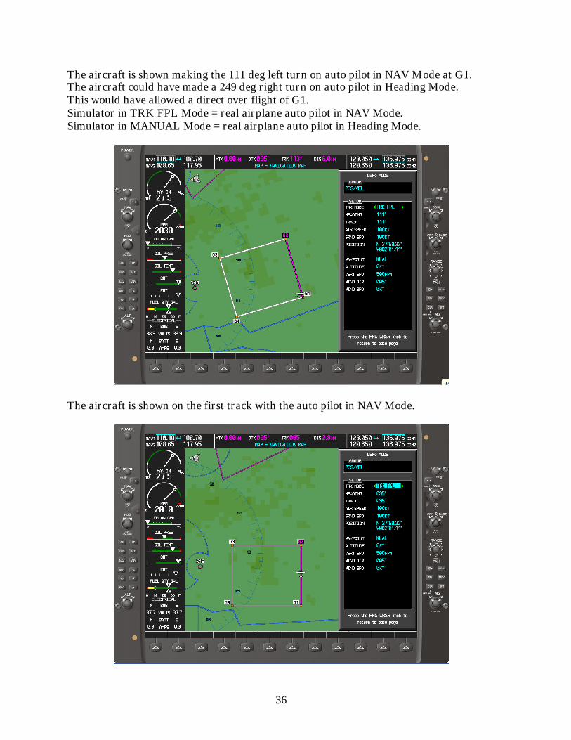
The aircraft is shown making the 111 deg left turn on auto pilot in NAV Mode at G1.The aircraft could have made a 249 deg right turn on auto pilot in Heading Mode.This would have allowed a direct over flight of G1.Simulator in TRK FPL Mode = real airplane auto pilot in NAV Mode.Simulator in MANUAL Mode = real airplane auto pilot in Heading Mode.
The aircraft is shown on the first track with the auto pilot in NAV Mode.

37
Change TRK MODE to Manual by turning Inner FMS knob counter-clockwise.This is equivalent to putting the real aircraft’s auto pilot in Heading Mode.Then move the cursor down to HEADING using the Outer FMS knob.
Set the HEADING to 275 deg. If the turn is early, reset the HEADING to 295 deg and iflate to 255 deg. Correct to 275 deg when the desired cross track error of 1 nm is reached.

38
Target Values:
The 1st search leg: XTK = 0.0 nm; DTK = 95 deg; TRK = 95 deg
The 2nd search leg: XTK = 1.0 nm; DTK = 95 deg; TRK = 275 deg
The 3rd search leg: XTK = 2.0 nm; DTK = 95 deg; TRK = 95 deg
The 4th search leg: XTK = 3.0 nm; DTK = 95 deg; TRK = 275 deg
The additional 5 deg, (90 + 5) and (270 + 5), is the magnetic variation inMiami Grid 4D.
MARK A TARGET
Press the RANGE-PAN knob when the aircraft flies over the target. Thiswill put a white cross on the MFD. Do not toggle the RANGE-PAN knobafter marking. This will change the marked location. Write down theLatitude and Longitude of the marked location. It is displayed upper leftcorner of the MFD.
If you want to name the marked target, press the ENTER key to go direct tothe USER WAYPOINT page. Using Inner and Outer FMS knobs to namethe marked target and press the ENTER key.

39
Press the PAN-RANGE knob over the target, and then press the ENTERkey go direct to the USER WAYPOINT page.
Name the marked target using the Inner and Outer FMS knob.
Press the ENTER key to save the location of MARK.

40
Press the FMS knob and then hold the CLR key to return to the MAP page.The holding of the CLR key does not work on the G1000 Trainer. Use theOuter FMS knob.