g. pulla reddy engineering college (autonomous): …
TRANSCRIPT

G. PULLA REDDY ENGINEERING COLLEGE (AUTONOMOUS): KURNOOLDEPARTMENT OF ELECTRICAL & ELECTRONICS ENGINEERING
B.TECH EEE IV SEMESTERELECTRICAL MACHINES – I (EMC-I(P)) LABORATORY
TITLE: OCC OF DC SHUNT GENERATOR GPRECD/EEE/EXPT-EMC-I(P)-1SCHEME-17 DATE: 01-07-2018
Objective:To obtain the open circuit characteristics of the given DC shunt generator at its
rated speed and determine the Critical resistance and Critical speed.
Apparatus: DC Motor Generator Set, Rheostat, Voltmeters, Ammeters, Tachometer, Required number of connecting wires
Name plate details:
Fuse ratings:
Theory: The O.C.C is a curve showing the relationship between the no load emf generated and theshunt field current (Eo and If ). Even when the field current is zero there is some residualmagnetism present in the poles. Hence there is a small voltage generated even at zero fieldcurrent, which is called the residual voltage. As the field current is increased, Eo alsoincreases and the curve traced is almost a straight line. As I f is further increased the polesstart getting saturated, the straight line relation no longer holds good and the curve bendsand becomes almost horizontal.In a D.C. generator, for any given speed, the induced emf in the armature is directlyproportional to the flux per pole.Eg =(ΦZNP)/60A VoltsWhere Ф is the flux per pole in webers,Z is the no. of conductors in the armature,N is the speed of the shaft in rpm,P is the no. of poles andA is the no. of parallel paths.A = 2 (wave)A = P (lap)Critical resistance:It is that value of resistance in the field circuit at which the generator will just excite (orvoltage build up begins). If the resistance is higher, the machine will fail to build upvoltage. It is given by the slope of the tangent drawn to the linear portion of themagnetization curve from the origin.
Page 1 of 5
Prepared by: Approved by: Revision No. 0 Dr.V.Anantha Lakshmi Dr.T.Bramhananda Reddy Associate Professor HOD, EEE Dept

G. PULLA REDDY ENGINEERING COLLEGE (AUTONOMOUS): KURNOOLDEPARTMENT OF ELECTRICAL & ELECTRONICS ENGINEERING
B.TECH EEE IV SEMESTERELECTRICAL MACHINES – I (EMC-I(P)) LABORATORY
TITLE: OCC OF DC SHUNT GENERATOR GPRECD/EEE/EXPT-EMC-I(P)-1SCHEME-17 DATE: 01-07-2018
Conditions for voltage build up in a d.c shunt generator1. There should be some residual magnetism in the poles.2. For the given direction of rotation, the shunt field coils should be properly connected. The coils should be so connected that the flux generated by the field current aids the residual flux.3. When excited at no load, the shunt field circuit resistance should be less than the critical resistance.
Critical speed:
It is that value of speed at which the given shunt field resistance represents the critical resistance.
Procedure:
1. Connections are made as per the circuit diagram.2. Motor field rheostat is kept in minimum position.3. Generator field rheostat is kept in maximum position.4. D.C. Generator is driven at its rated speed with the help of prime mover (DC
shunt motor).5. Gradually the field rheostat of generator is varied in steps to get field current in
steps and armature terminal voltage is measured in each step.6. Step 5 is repeated till 120% of rated voltage is obtained.7. Then, the field current of generator is decreased and the armature terminal
voltage is noted in each step.8. The O.C.C curve is plotted
Observations:
If (A) Vf (V) Eg(V)Forward Reverse Average Forward Reverse Average Forward Reverse Average
Page 2 of 5
Prepared by: Approved by: Revision No. 0 Dr.V.Anantha Lakshmi Dr.T.Bramhananda Reddy Associate Professor HOD, EEE Dept

G. PULLA REDDY ENGINEERING COLLEGE (AUTONOMOUS): KURNOOLDEPARTMENT OF ELECTRICAL & ELECTRONICS ENGINEERING
B.TECH EEE IV SEMESTERELECTRICAL MACHINES – I (EMC-I(P)) LABORATORY
TITLE: OCC OF DC SHUNT GENERATOR GPRECD/EEE/EXPT-EMC-I(P)-1SCHEME-17 DATE: 01-07-2018
GRAPHS:
Critical Speed NC =(BC/AC)*NS
Critical Resistance=AB/BX
RESULT:
REMARKS IF ANY:
Page 3 of 5
Prepared by: Approved by: Revision No. 0 Dr.V.Anantha Lakshmi Dr.T.Bramhananda Reddy Associate Professor HOD, EEE Dept
X
Eg
Air gap Line OCC
Vf
A
B
If
C

G. PULLA REDDY ENGINEERING COLLEGE (AUTONOMOUS): KURNOOLDEPARTMENT OF ELECTRICAL & ELECTRONICS ENGINEERING
B.TECH EEE IV SEMESTERELECTRICAL MACHINES – I (EMC-I(P)) LABORATORY
TITLE: OCC OF DC SHUNT GENERATOR GPRECD/EEE/EXPT-EMC-I(P)-1SCHEME-17 DATE: 01-07-2018
Circuit Diagram:
Page 4 of 5
Prepared by: Approved by: Revision No. 0 Dr.V.Anantha Lakshmi Dr.T.Bramhananda Reddy Associate Professor HOD, EEE Dept

G. PULLA REDDY ENGINEERING COLLEGE (AUTONOMOUS): KURNOOLDEPARTMENT OF ELECTRICAL & ELECTRONICS ENGINEERING
B.TECH EEE IV SEMESTERELECTRICAL MACHINES – I (EMC-I(P)) LABORATORY
TITLE: OCC OF DC SHUNT GENERATOR GPRECD/EEE/EXPT-EMC-I(P)-1SCHEME-17 DATE: 01-07-2018
Viva Questions:
1. What is the need for starter in a d.c motor?2. How does a 3-point starter function?3. Why is Rheostat of dc motor kept in minimum position at starting?4. Why is Rheostat of generator kept in maximum position at start up?5. What is residual voltage? How is it measured?6. What is critical resistance? How can it be determined?7. What are the conditions necessary for voltage build up in a d.c shunt generator?8. What is critical speed?9. Explain the shape of OCC.
Page 5 of 5
Prepared by: Approved by: Revision No. 0 Dr.V.Anantha Lakshmi Dr.T.Bramhananda Reddy Associate Professor HOD, EEE Dept

G. PULLA REDDY ENGINEERING COLLEGE (AUTONOMOUS): KURNOOLDEPARTMENT OF ELECTRICAL & ELECTRONICS ENGINEERING
B.TECH EEE IV SEMESTERELECTRICAL MACHINES-I (EMC-I(P)) LABORATORY
TITLE: LOAD TEST ON DC SHUNT GPRECD/EEE/EXPT-EMC-I(P)-2GENERATOR SCHEME-17DATE: 01-07-2018
Objective:To conduct load test on DC shunt generator and to draw the external and internal
characteristics of DC shunt generator.
Apparatus:
DC Motor-Generator Set, Voltmeters, Ammeters, Tachometer, Rheostat, Required numberof connecting wires Name plate details:
Fuse ratings:
Theory:
Load characteristics of the machine can be broadly classified into:-1) External characteristics2) Internal CharacteristicsExternal Characteristics(V vs IL)It is a curve showing the variation in terminal voltage of the generator as the load on thegenerator is increased. The characteristics are as shown in the figure. At no load, theterminal voltage of the generator is at its rated value. As the load current is increased theterminal voltage drops. The drop in terminal voltage is due to the following reasons:-1. For a generator V = Eg − IaRa, as the load current increases, Ia increases, IaRa dropincreases, thus decreasing the terminal voltage V.2. As the load current increases, Ia increases, armature reaction effect also increases. Dueto demagnetizing effect of armature reaction, the induced emf Eg decreases, therebydecreasing V.3. Due to reasons (1) and (2), the terminal voltage decreases, which in turn reduces thefield current Ish, thereby decreasing Eg causing further decrease in V.
Page 1 of 5
Prepared by: Approved by: Revision No: 0Dr.V.Anantha Lakshmi Dr.T.Bramhananda Reddy Associate Professor HOD, EEE Dept

G. PULLA REDDY ENGINEERING COLLEGE (AUTONOMOUS): KURNOOLDEPARTMENT OF ELECTRICAL & ELECTRONICS ENGINEERING
B.TECH EEE IV SEMESTERELECTRICAL MACHINES-I (EMC-I(P)) LABORATORY
TITLE: LOAD TEST ON DC SHUNT GPRECD/EEE/EXPT-EMC-I(P)-2GENERATOR SCHEME-17DATE: 01-07-2018
Internal Characteristics [Eg vs Ia]It is a plot of the internally generated emf (Eg) and armature current (Ia). It is a curve similar to the external characteristics and lies above it.
Formulae used:Eg = V + IaRa
& Ia = IL + Ish
Procedure:
1. Circuit is connected as shown in the circuit diagram.2. After connecting the circuit, the motor field rheostat is kept at minimum position
and generator field rheostat is kept at maximum position.3. The generator is driven at its rated speed with the help of prime mover (DC motor).4. The generator field excitation is adjusted to get the rated no-load voltage on open
circuit.5. A resistive load is connected as shown in figur.6. The generator is loaded gradually upto full load.7. The field current of the generator is kept constant by adjusting the generator
rheostat.8. The speed of the motor is checked for different loads and it is kept constant by
adjusting the motor rheostat.9. The terminal voltage, load current and shunt field current are noted for various
loads.
Page 2 of 5
Prepared by: Approved by: Revision No: 0Dr.V.Anantha Lakshmi Dr.T.Bramhananda Reddy Associate Professor HOD, EEE Dept

G. PULLA REDDY ENGINEERING COLLEGE (AUTONOMOUS): KURNOOLDEPARTMENT OF ELECTRICAL & ELECTRONICS ENGINEERING
B.TECH EEE IV SEMESTERELECTRICAL MACHINES-I (EMC-I(P)) LABORATORY
TITLE: LOAD TEST ON DC SHUNT GPRECD/EEE/EXPT-EMC-I(P)-2GENERATOR SCHEME-17DATE: 01-07-2018
Observations:
If (A) IL (A) Ia (A)= IL+ If V (v) Eg= V +Ia (Ra+Rse)
Sample Calculations:
Terminal Voltage (V) = . . . . . . . . . VLoad Current (IL) = . . . . . . . . .AShunt Field Current (Ish) = . . . . . . . . .AArmature Current (Ia) = IL + Ish = . . . . . . . . .AGenerated emf (Eg) = V + Ia(Ra+Rse) = . . . . . . . . .Graphs:
Result:
Remarks if any:
Page 3 of 5
Prepared by: Approved by: Revision No: 0Dr.V.Anantha Lakshmi Dr.T.Bramhananda Reddy Associate Professor HOD, EEE Dept
Eo
Eg Vs I
a
V Vs IL
Load Current IL or
Armature Current Ia
Eg &V
Volts

G. PULLA REDDY ENGINEERING COLLEGE (AUTONOMOUS): KURNOOLDEPARTMENT OF ELECTRICAL & ELECTRONICS ENGINEERING
B.TECH EEE IV SEMESTERELECTRICAL MACHINES-I (EMC-I(P)) LABORATORY
TITLE: LOAD TEST ON DC SHUNT GPRECD/EEE/EXPT-EMC-I(P)-2GENERATOR SCHEME-17DATE: 01-07-2018
Circuit diagram:
Page 4 of 5
Prepared by: Approved by: Revision No: 0Dr.V.Anantha Lakshmi Dr.T.Bramhananda Reddy Associate Professor HOD, EEE Dept
A
I
f
AA
A
YY
+
_
_ ++
_
DPST
L LL F A
230V DC Supply
LOA
d
+ _
Z
I
L
AA
V
A
AAAA
ZZ
A
_
350Ω1.1A
350Ω1.1A
NVRC
OLRC
Z
ZZ

G. PULLA REDDY ENGINEERING COLLEGE (AUTONOMOUS): KURNOOLDEPARTMENT OF ELECTRICAL & ELECTRONICS ENGINEERING
B.TECH EEE IV SEMESTERELECTRICAL MACHINES-I (EMC-I(P)) LABORATORY
TITLE: LOAD TEST ON DC SHUNT GPRECD/EEE/EXPT-EMC-I(P)-2GENERATOR SCHEME-17DATE: 01-07-2018
Viva Questions:
1. What is the need for starter with a d.c motor?
2. How does a 3-point starter function?
3. Why is Rh1 kept in minimum position at starting?
4. Why is Rh2 kept in maximum position at starting?
5. Why does the terminal voltage of a generator decrease with increase in load?
6. How are the meter ratings selected for this experiment?
7. What are the different losses in a d.c generator?
8. What is the condition for maximum efficiency in a d.c machine?
9. What is armature reaction? How does it effect the functioning of the machine?
Page 5 of 5
Prepared by: Approved by: Revision No: 0Dr.V.Anantha Lakshmi Dr.T.Bramhananda Reddy Associate Professor HOD, EEE Dept

G. PULLA REDDY ENGINEERING COLLEGE (AUTONOMOUS): KURNOOLDEPARTMENT OF ELECTRICAL & ELECTRONICS ENGINEERING
B.TECH EEE IV SEMESTERELECTRICAL MACHINES-I (EMC-I(P)) LABORATORY
TITLE: BRAKE TEST ON DC GPRECD/EEE/EXPT-EMC-I(P)-3 COMPOUND MOTOR DATE: 01-07-2018 SCHEME-17
Objective:To conduct brake test on DC compound motor for long shunt cumulative &
differential connections and to draw the performance characteristics.
Apparatus: DC Compound Motor, Voltmeter, Ammeter, Tachometer, Required number of connecting wires Name plate details:
Fuse ratings:
Theory:
This is a direct method of testing a dc compound motor as a cumulative and as aDifferential compound motor. In this method, a rope is wound round the pulley and itstwo ends attached to two spring balances S1 and S2.The tensions on the rope T1 and T2can be adjusted with the help of swivels. The force acting tangentially on the pulley isequal to the difference between the readings of the two spring balances. Power developedin the motor at the shaft = Pout = T ×ω watts where ω= (2N)/ 60 (N is speed in r.p.m) ; Tshaft = F× r Newton-metre= (T1~T2) Kg × 9.8× r = Motor output Pout = Tshaft× ω = (2ΠNTshaft)/ 60(R is radius of the pulley in meter and 1kg wt = 9.8 Newton)Total power input to the motor Pin=Power input to the fieldPin = Vf If + Va Ia
% Efficiency = (Pout / Pin)x 100In a separately excited cumulatively compound motor Φsh is constant. Hence, Φse
increases with increase in the load or armature current. Thus, the speed drops at a fasterrate in a cumulative compound motor than in a shunt motor.
Ta=KΦIa.Where Φ = Φsh + Φse; Φsh is constant. Φse increases with increase in Ia. Hence Ta
Page 1 of 7
Prepared by: Approved by Revision No : 0Dr.V.Anantha Lakshmi Dr.T.Bramhananda Reddy Associate Professor HOD, EEE Dept

G. PULLA REDDY ENGINEERING COLLEGE (AUTONOMOUS): KURNOOLDEPARTMENT OF ELECTRICAL & ELECTRONICS ENGINEERING
B.TECH EEE IV SEMESTERELECTRICAL MACHINES-I (EMC-I(P)) LABORATORY
TITLE: BRAKE TEST ON DC GPRECD/EEE/EXPT-EMC-I(P)-3 COMPOUND MOTOR DATE: 01-07-2018 SCHEME-17
increases.
If Φsh is stronger than Φse, the Ta~ Ia characteristic and Speed~Torque characteristicapproaches to the shunt motor characteristics. If Φse is stronger than Φsh, abovecharacteristics approaches to the series motor characteristics.
In a Differential Compound motor, the series flux opposes the shunt flux. With increasein Ia, the net flux in the air gap deceases. Thus, the motor speed increases slightly withload.
Hence, it can be designed to give a constant speed under all load conditions.Formulae used:
Procedure:
1) Circuit is connected as per the circuit diagram.2) The field rheostat of motor is kept at minimum position.3) Machine is started at no load initially, speed is adjusted with the help of
its rheostat at the rated speed and meter readings are noted.4) By increasing load on the brake drum and by tightening the belt the
corresponding meter readings are noted.5) The same procedure is followed for differential compound motor also.
Observations:
Cumulative Compound Motor:
Voltage(V) IL (A) Speed (N) (RPM)
BalanceTorqueT=(T1~ T2)rg
O/p=2πNT 60
I/P=V IL
η=o/p / i/p
T1 T2
Page 2 of 7
Prepared by: Approved by Revision No : 0Dr.V.Anantha Lakshmi Dr.T.Bramhananda Reddy Associate Professor HOD, EEE Dept

G. PULLA REDDY ENGINEERING COLLEGE (AUTONOMOUS): KURNOOLDEPARTMENT OF ELECTRICAL & ELECTRONICS ENGINEERING
B.TECH EEE IV SEMESTERELECTRICAL MACHINES-I (EMC-I(P)) LABORATORY
TITLE: BRAKE TEST ON DC GPRECD/EEE/EXPT-EMC-I(P)-3 COMPOUND MOTOR DATE: 01-07-2018 SCHEME-17
Differential Compound Motor:Voltage(V) IL (A) Speed
(N) (RPM)
BalanceTorqueT=(T1~T2)rg
O/p=2πNT 60
I/P=V IL
%η=[O/p / I/p]*100
T1 T2
Sample Calculations:Cumulative compounding:Input Voltage (V)= VInput current = IL= AN= rpmT1 = kg; T2 = kg.T=(T1-T2)rg = NmOutput = O/p= (2πNT)/60Input = VIL= %Efficiency = %η=[(O/p) / (I/p)]*100
Differential Compounding:Input Voltage (V)= VInput current = IL= AN= rpmT1 = kg; T2 = kg.T=(T1-T2)rg = NmOutput = O/p= (2πNT)/60
Page 3 of 7
Prepared by: Approved by Revision No : 0Dr.V.Anantha Lakshmi Dr.T.Bramhananda Reddy Associate Professor HOD, EEE Dept

G. PULLA REDDY ENGINEERING COLLEGE (AUTONOMOUS): KURNOOLDEPARTMENT OF ELECTRICAL & ELECTRONICS ENGINEERING
B.TECH EEE IV SEMESTERELECTRICAL MACHINES-I (EMC-I(P)) LABORATORY
TITLE: BRAKE TEST ON DC GPRECD/EEE/EXPT-EMC-I(P)-3 COMPOUND MOTOR DATE: 01-07-2018 SCHEME-17
Input = VIL= %Efficiency = %η = [(O/p) / (I/p)]*100
Graphs:
Result:
Remarks if any:
Page 4 of 7
Prepared by: Approved by Revision No : 0Dr.V.Anantha Lakshmi Dr.T.Bramhananda Reddy Associate Professor HOD, EEE Dept

G. PULLA REDDY ENGINEERING COLLEGE (AUTONOMOUS): KURNOOLDEPARTMENT OF ELECTRICAL & ELECTRONICS ENGINEERING
B.TECH EEE IV SEMESTERELECTRICAL MACHINES-I (EMC-I(P)) LABORATORY
TITLE: BRAKE TEST ON DC GPRECD/EEE/EXPT-EMC-I(P)-3 COMPOUND MOTOR DATE: 01-07-2018 SCHEME-17
Circuit Diagram:
Cumulative Compound Motor:
Page 5 of 7
Prepared by: Approved by Revision No : 0Dr.V.Anantha Lakshmi Dr.T.Bramhananda Reddy Associate Professor HOD, EEE Dept
L LL F AYYY_+
_
+
_
+
230V DC Supply
DPST V
A
ZZ
ZAA
A
T1
Brake Drum
T2

G. PULLA REDDY ENGINEERING COLLEGE (AUTONOMOUS): KURNOOLDEPARTMENT OF ELECTRICAL & ELECTRONICS ENGINEERING
B.TECH EEE IV SEMESTERELECTRICAL MACHINES-I (EMC-I(P)) LABORATORY
TITLE: BRAKE TEST ON DC GPRECD/EEE/EXPT-EMC-I(P)-3 COMPOUND MOTOR DATE: 01-07-2018 SCHEME-17
Differential Compound Motor:
Page 6 of 7
Prepared by: Approved by Revision No : 0Dr.V.Anantha Lakshmi Dr.T.Bramhananda Reddy Associate Professor HOD, EEE Dept
L LL F A Y YY_+
_
+
_
+
230V DC Supply
DPST V
A
ZZ
ZAA
A
T1
Brake Drum
T2
G. PULLA REDDY ENGINEERING COLLEGE (AUTONOMOUS): KURNOOLDEPARTMENT OF ELECTRICAL & ELECTRONICS ENGINEERING
B.TECH EEE IV SEMESTERELECTRICAL MACHINES-I (EMC-I(P)) LABORATORY
TITLE: BRAKE TEST ON DC GPRECD/EEE/EXPT-EMC-I(P)-3 COMPOUND MOTOR DATE: 01-07-2018 SCHEME-17
Viva Questions:
1. On what principle does DC motor operates?
2. What are the applications of DC Compound motors?
3. What is the typical brush drop in DC motors?
4. Draw different characteristic curves of DC compound motors?
5. Explain cumulative compound machine.
6. Write the corresponding equations of Short shunt and long shunt compound
Motors.
Page 7 of 7
Prepared by: Approved by Revision No : 0Dr.V.Anantha Lakshmi Dr.T.Bramhananda Reddy Associate Professor HOD, EEE Dept

G.PULLA REDDY ENGINEERING COLLEGE (AUTONOMOUS): KURNOOLDEPARTMENT OF ELECTRICAL & ELECTRONICS ENGINEERING
B.TECH EEE IV SEMESTERELECTRICAL MACHINES-I (EMC-I(P)) LABORATORY
TITLE : SWINBURNE’S TEST GPRECD/EEE/EXPT-EMC1-4 SCHEME-17 DATE: 01-07-2018
Objective:To conduct Swinburne’s test on DC shunt machine and to predetermine its efficiency both as a Generator and Motor.
Apparatus:
DC Shunt Motor, Voltmeter, Ammeters, SPST Switch, Tachometer, Required number of connecting wires
Name plate details:
Fuse rating:
Formulae used: No Load armature current = Iao
No Load input = VILo Watts No Load armature Cu loss = Iao
2 Ra
Shunt field losss = VIf
Constant losses of machine, Pc= VILo - Iao2 Ra -VIf
Where Ia = Armature current (at any load) Ra = Armature resistance
As Motor: Load current = IL amps Field current = If amps Armature cu loss= Ia
2 Ra watts
Ia = IL - If
Total losses, PL=PC+ armature ‘cu’ loss + Shunt field losss Input power = V IL watts,
Page 1 of 7
Prepared by: Approved by: Revision No: 0Dr.V.Anantha Lakshmi Dr. T.Bramhananda Reddy Associate Professor HOD, EEE Dept
G.PULLA REDDY ENGINEERING COLLEGE (AUTONOMOUS): KURNOOLDEPARTMENT OF ELECTRICAL & ELECTRONICS ENGINEERING
B.TECH EEE IV SEMESTERELECTRICAL MACHINES-I (EMC-I(P)) LABORATORY
TITLE : SWINBURNE’S TEST GPRECD/EEE/EXPT-EMC1-4 SCHEME-17 DATE: 01-07-2018
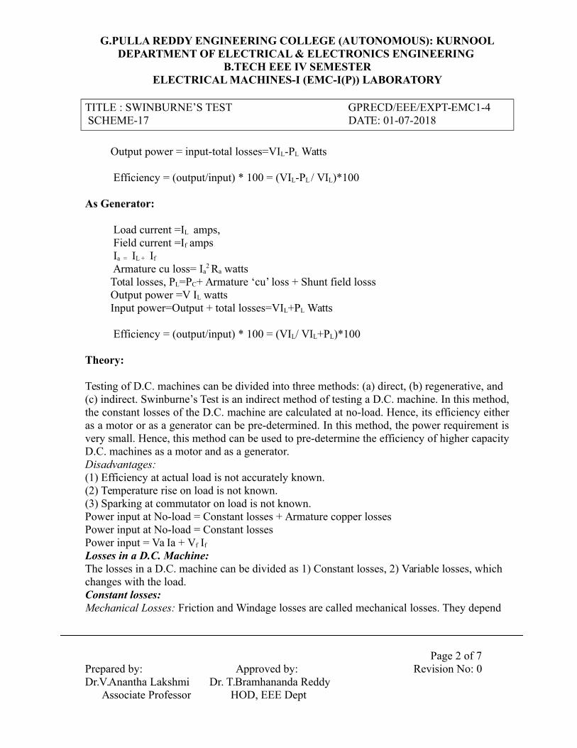
Output power = input-total losses=VIL-PL Watts
Efficiency = (output/input) * 100 = (VIL-PL / VIL)*100
As Generator: Load current =IL amps, Field current =If amps Ia = IL + If
Armature cu loss= Ia2 Ra watts
Total losses, PL=PC+ Armature ‘cu’ loss + Shunt field losss Output power =V IL watts Input power=Output + total losses=VIL+PL Watts
Efficiency = (output/input) * 100 = (VIL/ VIL+PL)*100
Theory:
Testing of D.C. machines can be divided into three methods: (a) direct, (b) regenerative, and(c) indirect. Swinburne’s Test is an indirect method of testing a D.C. machine. In this method,the constant losses of the D.C. machine are calculated at no-load. Hence, its efficiency eitheras a motor or as a generator can be pre-determined. In this method, the power requirement isvery small. Hence, this method can be used to pre-determine the efficiency of higher capacityD.C. machines as a motor and as a generator.Disadvantages:(1) Efficiency at actual load is not accurately known.(2) Temperature rise on load is not known.(3) Sparking at commutator on load is not known.Power input at No-load = Constant losses + Armature copper lossesPower input at No-load = Constant lossesPower input = Va Ia + Vf If
Losses in a D.C. Machine:The losses in a D.C. machine can be divided as 1) Constant losses, 2) Variable losses, whichchanges with the load.Constant losses:Mechanical Losses: Friction and Windage losses are called mechanical losses. They depend
Page 2 of 7
Prepared by: Approved by: Revision No: 0Dr.V.Anantha Lakshmi Dr. T.Bramhananda Reddy Associate Professor HOD, EEE Dept

G.PULLA REDDY ENGINEERING COLLEGE (AUTONOMOUS): KURNOOLDEPARTMENT OF ELECTRICAL & ELECTRONICS ENGINEERING
B.TECH EEE IV SEMESTERELECTRICAL MACHINES-I (EMC-I(P)) LABORATORY
TITLE : SWINBURNE’S TEST GPRECD/EEE/EXPT-EMC1-4 SCHEME-17 DATE: 01-07-2018
upon the speed. A D.C. shunt machine is basically a constant speed machine both as agenerator and as a motor. Thus, the mechanical losses are constant.Iron Losses: For a D.C. shunt machine, the field current hence the flux. Hence, hysteresis andeddy current losses (which are also called as iron losses) remain constant.Field Copper Losses: Under normal operating conditions of a D.C. shunt machine, the fieldcurrent remains constant. Thus, power received by the field circuit (which is consumed asfield copper losses) is constant.Constant losses in a D.C. shunt machine = Mechanical losses + IronLosses + Field copperlosses
Variable Losses:The power lost in the armature circuit of s D.C. machine increases with the increase in load.Thus, the armature copper losses are called as variable losses.
Procedure:1. Connections are made as per the circuit diagram.2. Motor field rheostat is kept in minimum position.3. The SPST switch is kept in closed position on no load.4. Supply is given & motor is started with the help of four-point starter.5. The field rheostat is adjusted till the rated speed is achieved.6. Switch was opened and currents IL, IF & Voltmeter reading are noted.
Observations:
Motor:
V IL (A) IF(A) Ia = IL - If PL
Input(VIL)
Output(VIL- PL)
%Efficiency=(Output/input)*100
Generator:
Page 3 of 7
Prepared by: Approved by: Revision No: 0Dr.V.Anantha Lakshmi Dr. T.Bramhananda Reddy Associate Professor HOD, EEE Dept

G.PULLA REDDY ENGINEERING COLLEGE (AUTONOMOUS): KURNOOLDEPARTMENT OF ELECTRICAL & ELECTRONICS ENGINEERING
B.TECH EEE IV SEMESTERELECTRICAL MACHINES-I (EMC-I(P)) LABORATORY
TITLE : SWINBURNE’S TEST GPRECD/EEE/EXPT-EMC1-4 SCHEME-17 DATE: 01-07-2018
V IL (A) IF (A)Ia = IL+
IFPL Output
(VIL)
Input(VIL+ PL)
%Efficiency=(Output/input)*100
Sample Calculations:Armature copper loss = watts
Field copper loss = watts
Mechanical loss + iron losses =armature input – armature copper loss
Total constant losses = Mechanical loss + iron loss + field copper loss= watts
Efficiency as a motor:
Let us assume that the current drawn by the armature =
Input to the motor = input to the armature + input to the field = watts
Total losses = constant losses + armature copper losses = watts
Output = Input – total losses = watts
Efficiency, ηm = output/input = %
Efficiency as a generator:
Let us assume that the current delivered by the armature =
Output = watts
Total losses = constant losses + armature copper losses = watts
Efficiency, ηg = output/input = %
Page 4 of 7
Prepared by: Approved by: Revision No: 0Dr.V.Anantha Lakshmi Dr. T.Bramhananda Reddy Associate Professor HOD, EEE Dept
G.PULLA REDDY ENGINEERING COLLEGE (AUTONOMOUS): KURNOOLDEPARTMENT OF ELECTRICAL & ELECTRONICS ENGINEERING
B.TECH EEE IV SEMESTERELECTRICAL MACHINES-I (EMC-I(P)) LABORATORY
TITLE : SWINBURNE’S TEST GPRECD/EEE/EXPT-EMC1-4 SCHEME-17 DATE: 01-07-2018
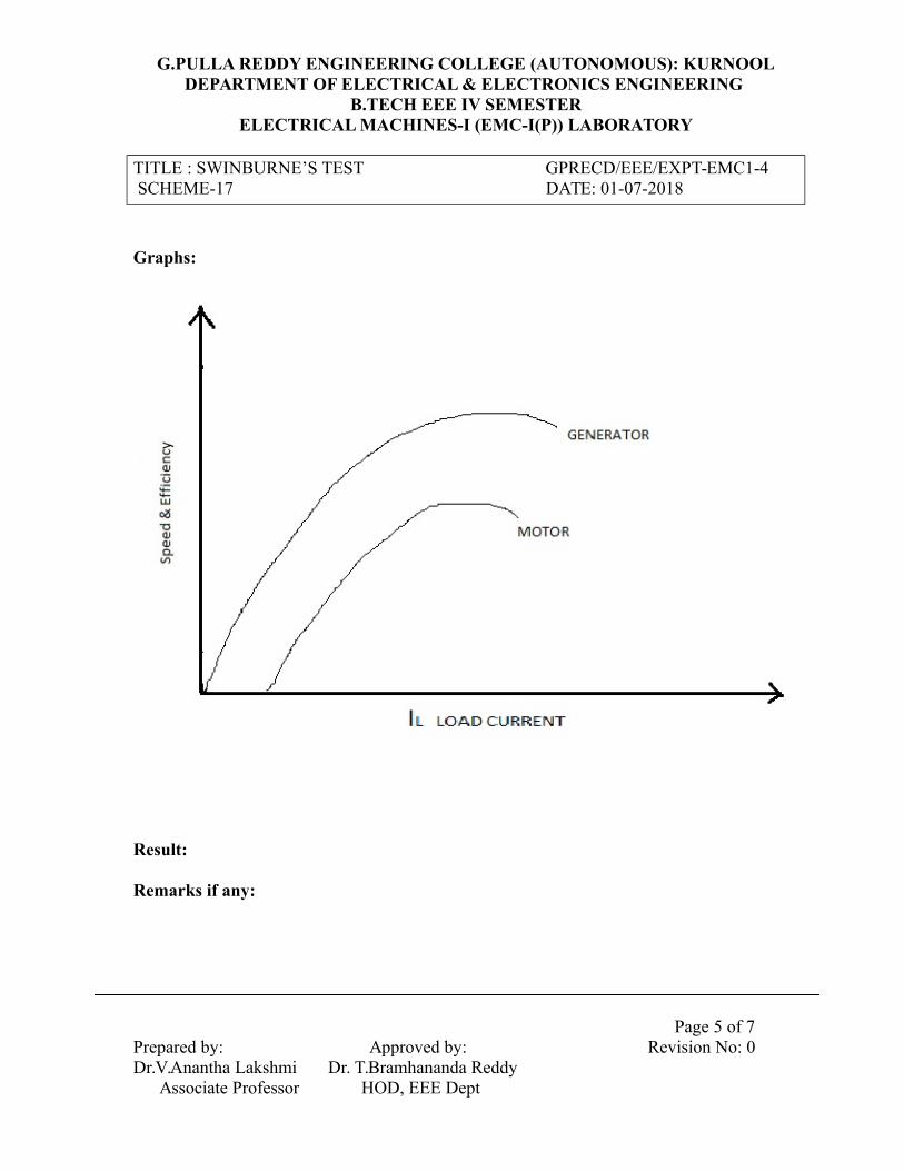
Graphs:
Result:
Remarks if any:
Page 5 of 7
Prepared by: Approved by: Revision No: 0Dr.V.Anantha Lakshmi Dr. T.Bramhananda Reddy Associate Professor HOD, EEE Dept
G.PULLA REDDY ENGINEERING COLLEGE (AUTONOMOUS): KURNOOLDEPARTMENT OF ELECTRICAL & ELECTRONICS ENGINEERING
B.TECH EEE IV SEMESTERELECTRICAL MACHINES-I (EMC-I(P)) LABORATORY
TITLE : SWINBURNE’S TEST GPRECD/EEE/EXPT-EMC1-4 SCHEME-17 DATE: 01-07-2018
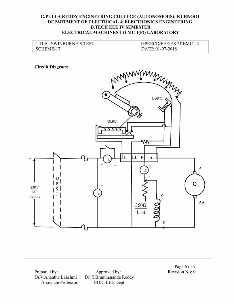
Circuit Diagram:
Page 6 of 7
Prepared by: Approved by: Revision No: 0Dr.V.Anantha Lakshmi Dr. T.Bramhananda Reddy Associate Professor HOD, EEE Dept
DPST
230V DC Supply V
L LL F AA
A
Z
ZZ
A
AA
+ _
+
_
+
_
A1.1
350
+
_
G.PULLA REDDY ENGINEERING COLLEGE (AUTONOMOUS): KURNOOLDEPARTMENT OF ELECTRICAL & ELECTRONICS ENGINEERING
B.TECH EEE IV SEMESTERELECTRICAL MACHINES-I (EMC-I(P)) LABORATORY
TITLE : SWINBURNE’S TEST GPRECD/EEE/EXPT-EMC1-4 SCHEME-17 DATE: 01-07-2018
Viva Questions:
1. What is the purpose of Swinburne’s test?
2. What are the constant losses in a DC machine?
3. What are the assumptions made in Swinburne’s test?
4. Why is the indirect method preferred to the direct loading test?
5. The efficiency of DC machine is generally higher when it works as a generator than
when it works as a motor. Is this statement true or false? Justify your answer with proper
reasons.
Page 7 of 7
Prepared by: Approved by: Revision No: 0Dr.V.Anantha Lakshmi Dr. T.Bramhananda Reddy Associate Professor HOD, EEE Dept

G.PULLA REDDY ENGINEERING COLLEGE (AUTONOMOUS): KURNOOLDEPARTMENT OF ELECTRICAL & ELECTRONICS ENGINEERING
B.TECH EEE IV SEMESTERELECTRICAL MACHINES-I (EMC-I(P)) LABORATORY
TITLE: 4-POINT STARTER GPRECD/EEE/EXPT-EMC1SCHEME-13 DATE: 01-07-2016
4-Point Starter
Page 1 of 1
Prepared by: Approved by: Revision No : 1Sri. C. Harinatha Reddy Dr.T.Bramhananda Reddy HOD, EEE Dept
L LL F A

G.PULLA REDDY ENGINEERING COLLEGE (AUTONOMOUS): KURNOOLDEPARTMENT OF ELECTRICAL & ELECTRONICS ENGINEERING
B.TECH EEE IV SEMESTERELECTRICAL MACHINES-I (EMC-I(P)) LABORATORY
TITLE: BRAKE TEST ON GPRECD/EEE/EXPT-EMC1- 5 DC SHUNT MOTOR DATE: 01-07-2018SCHEME-17
Objective:To conduct brake test on D.C.Shunt Motor and to draw the performance characteristics.
Apparatus: DC Shunt Motor, Voltmeter, Ammeter, Tachometer, Required number of connecting wires
Name plate details:
Fuse ratings:
Theory:This is a direct method of testing a dc machine. It is a simple method of measuring motoroutput, speed and efficiency etc., at different load conditions. A rope is wound round thepulley and its two ends are attached to two spring balances S1 and S2.The tensionsprovided by the spring balances S1 and S2 are T1 and T2. The tension of the rope can beadjusted with the help of swivels. The force acting tangentially on the pulley is equal tothe difference between the readings of the two spring balances in Kg - force.The induced voltage Eb = V - Ia Ra and Eb = KΦN, Thus, KΦ =Eb/ N
Where V = applied voltage, Ia = armature current, Ra = armature resistance.Total power input to the motor Pin = field circuit power + Armature power = VfIf + VaIaIf ‘r’ is the radius of the pulley, then torque at the pulley is given byTshaft = 9.81(T1~ T2) rMotor output power Pout = Tshaft * ω = (Tshaft x 2ΠN)/60%Efficiency = (Output power/Input power)x100A dc shunt motor rotates due to the torque developed in the armature when the armatureand field terminals are connected to the dc supply. The direction of rotation can beexplained with help of Fleming’s left hand principle. A counter emf or back emf (Eb) isinduced in the armature conductors while the armature (rotor) rotating in the magneticfield. The direction of the induced emf can be explained with the help of Fleming’s righthand principle and Lenz’s law. The direction this induced emf is such that it opposes theapplied voltage (V). This induced emf is also called as back emf Eb.
The equation of the motor is V = Eb + IaRa
Page 1 of 6Prepared by: Approved by: Revision No : 0Dr.V.Anantha Lakshmi Dr.T.Bramhananda Reddy Associate Professor HOD, EEE Dept

G.PULLA REDDY ENGINEERING COLLEGE (AUTONOMOUS): KURNOOLDEPARTMENT OF ELECTRICAL & ELECTRONICS ENGINEERING
B.TECH EEE IV SEMESTERELECTRICAL MACHINES-I (EMC-I(P)) LABORATORY
TITLE: BRAKE TEST ON GPRECD/EEE/EXPT-EMC1- 5 DC SHUNT MOTOR DATE: 01-07-2018SCHEME-17
The value of ‘Eb’ is zero while starting the motor. Hence, the voltage across the armaturehas to be increased gradually.
The power developed in the rotor (armature) =EbIa = Tω where Eb=( ΦZNP)/60A and Ia = (V-Eb)/ Ra ; Where ω=2N/60 is the angular velocity ofthe pulley, in rad/sec. In a dc motor T α ΦIa,; Where Φ= Flux produced by the shunt fieldper pole ; Ia= Armature currentThe torque developed in the motor is opposed by the torques due to(a) Friction and windage(b) Eddy currents and hysteresis and(c) Mechanical load connected at the shaft.The motor runs at a stable speed when the developed torque and resisting torques balanceeach other.Let a small load be increased, and then the resisting torque increases and motor speedfalls. Theback emf reduces due to the fall in the speed. Hence, the armature current
increases. (Ia =V EbRa. If Φ is assumed constant, (i.e., neglecting the armaturereaction) the torque developed by the motor increases and a new stable speed is reachedat which the developed torque equals the resisting torque.
Armature current ~ Speed characteristics:The armature current Ia increases with increase in the load at the shaft. Hence IaRa dropincreases and counter emf (Eb) decreases.Eb = V- IaRa,Where Ra is armature resistance and Eb α ΦN.If Φ is constant in the shunt motor, by neglecting the armature reaction; the speed falls asEb falls. In a dc motor Ra is very small, hence IaRa is a small value and fall in Eb withincrease in load is small. Thus, the speed falls slightly as Ia increases.Armature current ~ Torque characteristics:If Φ is constant, developed torque increases with increase in Ia. T = KΦIa In actualcondition, Φ slightly falls with increase in Ia due to the effect of armature reaction.Armature current ~ induced emf (back emf):Induced emf (back emf Eb) falls slightly with increase in Ia as per the equationEb = V - IaRa
Torque ~ Speed:
Page 2 of 6Prepared by: Approved by: Revision No : 0Dr.V.Anantha Lakshmi Dr.T.Bramhananda Reddy Associate Professor HOD, EEE Dept

G.PULLA REDDY ENGINEERING COLLEGE (AUTONOMOUS): KURNOOLDEPARTMENT OF ELECTRICAL & ELECTRONICS ENGINEERING
B.TECH EEE IV SEMESTERELECTRICAL MACHINES-I (EMC-I(P)) LABORATORY
TITLE: BRAKE TEST ON GPRECD/EEE/EXPT-EMC1- 5 DC SHUNT MOTOR DATE: 01-07-2018SCHEME-17
With increase in load, Ia and Ta increase since the shunt field Φ is constant. The fall in speed is very small as the IaRa drop is very small compared to V. In a dc shunt motor N α Eb/ Output ~ Efficiency:The graph between Output ~ Efficiency indicates that max torque occurs when armature copper losses is equal to the constant losses. (Sum of field copper losses, mechanical losses and Iron losses).
Procedure:
1) Circuit is connected as per the circuit diagram.2) The motor Rheostat is kept at minimum position.3) Ensure that initially there is no load on the motor.4) Machine is started using the four-point starter and the speed of the motor
is adjusted to rated value by varying the field rheostat.5) Load the motor by tightening the belt on the pulley and record the
readings of all the meters, speed and the readings of both the springbalances.
6) Repeat step 5 by increasing the load on the motor in steps, till the ratedcurrent of the motor is obtained.
7) Remove the load gradually and then stop the motor by switching off thesupply.
Observations:
Voltage(V)
IL
(A)
Speed(N)
(RPM)
Balance Torque
T=(F1~F2) rg
O/p=2πNT 60
I/P=V IL
% η=[(O/p) /
(I/p)]*100F1 F2
r = radius of brake drum g = acceleration due to gravity
Graphs:
Page 3 of 6Prepared by: Approved by: Revision No : 0Dr.V.Anantha Lakshmi Dr.T.Bramhananda Reddy Associate Professor HOD, EEE Dept

G.PULLA REDDY ENGINEERING COLLEGE (AUTONOMOUS): KURNOOLDEPARTMENT OF ELECTRICAL & ELECTRONICS ENGINEERING
B.TECH EEE IV SEMESTERELECTRICAL MACHINES-I (EMC-I(P)) LABORATORY
TITLE: BRAKE TEST ON GPRECD/EEE/EXPT-EMC1- 5 DC SHUNT MOTOR DATE: 01-07-2018SCHEME-17
Result:
Remarks if any:
Page 4 of 6Prepared by: Approved by: Revision No : 0Dr.V.Anantha Lakshmi Dr.T.Bramhananda Reddy Associate Professor HOD, EEE Dept

G.PULLA REDDY ENGINEERING COLLEGE (AUTONOMOUS): KURNOOLDEPARTMENT OF ELECTRICAL & ELECTRONICS ENGINEERING
B.TECH EEE IV SEMESTERELECTRICAL MACHINES-I (EMC-I(P)) LABORATORY
TITLE: BRAKE TEST ON GPRECD/EEE/EXPT-EMC1- 5 DC SHUNT MOTOR DATE: 01-07-2018SCHEME-17
Circuit Diagram:
Page 5 of 6Prepared by: Approved by: Revision No : 0Dr.V.Anantha Lakshmi Dr.T.Bramhananda Reddy Associate Professor HOD, EEE Dept
_
+T
1
Brake Drum
T2
DPST
230V DC Supply
350Ω 1.1A
Z
ZZ
AA
A
+ _
+
_
V
L LL F A AA

G.PULLA REDDY ENGINEERING COLLEGE (AUTONOMOUS): KURNOOLDEPARTMENT OF ELECTRICAL & ELECTRONICS ENGINEERING
B.TECH EEE IV SEMESTERELECTRICAL MACHINES-I (EMC-I(P)) LABORATORY
TITLE: BRAKE TEST ON GPRECD/EEE/EXPT-EMC1- 5 DC SHUNT MOTOR DATE: 01-07-2018SCHEME-17
Viva Questions:
1. Why should the field rheostat be kept in the position of minimum resistance?
2. What is the loading arrangement used in a dc motor?
3. How can the direction of rotation of a DC shunt motor be reversed?
4. What are the mechanical and electrical characteristics of a DC shunt motor?
5. What are the applications of a DC shunt motor?
Page 6 of 6Prepared by: Approved by: Revision No : 0Dr.V.Anantha Lakshmi Dr.T.Bramhananda Reddy Associate Professor HOD, EEE Dept

G.PULLA REDDY ENGINEERING COLLEGE (AUTONOMOUS): KURNOOLDEPARTMENT OF ELECTRICAL & ELECTRONICS ENGINEERING
B.TECH EEE IV SEMESTERELECTRICAL MACHINES-I (EMC-I(P)) LABORATORY
TITLE: HOPKINSON’S TEST GPRECD/EEE/EXPT-EMC1-6 SCHEME-17 DATE: 01-07-2018
Objective:To conduct Hopkinson’s test on two identical DC machines and determine
efficiencies of two machines.
Apparatus:
Name plate details:
Theory:
To find efficiency of a dc shunt machine, the best method is to directly load it andmeasure its output and input. For large rating machines the direct load test method isdifficult to conduct due to a) It is costly to obtain a suitable load and b) The amount ofenergy to be spent for testing is too large. For, these reasons, electrical engineers useindirect methods like Swinburne’s test, Separation of losses, and the Retardation test etc,are used to determine the efficiency. These tests are simple to carry out but they offer noinformation about how the machine performs under actual load conditions. Also, becauseof assumptions the results obtained are not so accurate.
Hopkinson’s test (also called Regenerative or Back-to-Back test) offers theadvantages of load test without its disadvantages. By this method, full-load test can becarried out on two identical shunt machines without wasting theirs outputs. The twomachines are mechanically coupled and are so adjusted that one of them runs as a motorand the other as a generator. The mechanical output of the motor drives the generator. Thegenerator emf value is brought to the bus bar voltage and then paralleled it to bus bars.The electrical output of the generator is used in supplying the greater part of input to themotor. If there were no losses in the machines, then they would have run without anyexternal power supply. But due to losses, generator output is not sufficient to drive themotor and vice versa. Thus, these losses in the machines are supplied electrically fromthe supply mains.
Procedure:
1. Circuit is connected as shown in the circuit diagram.2. The motor field rheostat is kept at minimum position and generator field rheostat
is kept at maximum position.3. Motor is started with the help of starter at no load.
Page 1 of 5Prepared by: Approved by: Revision No:0Dr.V.Anantha Lakshmi Dr.T.Bramhananda Reddy Associate Professor HOD, EEE Dept
G.PULLA REDDY ENGINEERING COLLEGE (AUTONOMOUS): KURNOOLDEPARTMENT OF ELECTRICAL & ELECTRONICS ENGINEERING
B.TECH EEE IV SEMESTERELECTRICAL MACHINES-I (EMC-I(P)) LABORATORY
TITLE: HOPKINSON’S TEST GPRECD/EEE/EXPT-EMC1-6 SCHEME-17 DATE: 01-07-2018
4. The motor is to be made to run at rated speed by adjusting the motor field rheostatvalue.
5. The generator field resistance is varied so that voltmeter reads zero volts acrossthe SPST switch, at that moment SPST switch is closed.
6. The generator field resistance is varied in steps and corresponding readings arenoted.
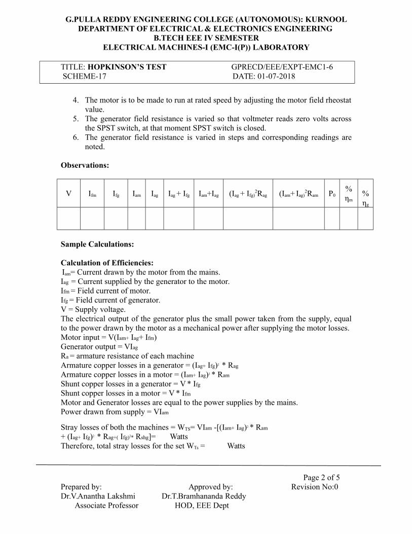
Observations:
V Ifm Ifg Iam Iag Iag + Ifg Iam+Iag (Iag + Ifg)2Rag (Iam+ Iag)
2Ram P0%ηm
%ηg
Sample Calculations:
Calculation of Efficiencies: Iam= Current drawn by the motor from the mains.Iag = Current supplied by the generator to the motor.Ifm = Field current of motor.Ifg = Field current of generator.V = Supply voltage.The electrical output of the generator plus the small power taken from the supply, equalto the power drawn by the motor as a mechanical power after supplying the motor losses.Motor input = V(Iam+ Iag+ Ifm)Generator output = VIag
Ra = armature resistance of each machineArmature copper losses in a generator = (Iag+ Ifg)2 * Rag
Armature copper losses in a motor = (Iam+ Iag)2 * Ram
Shunt copper losses in a generator = V * Ifg
Shunt copper losses in a motor = V * Ifm
Motor and Generator losses are equal to the power supplies by the mains.Power drawn from supply = VIam
Stray losses of both the machines = WTS= VIam -[(Iam+ Iag)2 * Ram
+ (Iag+ Ifg)2 * Rag+( Ifg)2* Rshg]= WattsTherefore, total stray losses for the set WTs = Watts
Page 2 of 5Prepared by: Approved by: Revision No:0Dr.V.Anantha Lakshmi Dr.T.Bramhananda Reddy Associate Professor HOD, EEE Dept

G.PULLA REDDY ENGINEERING COLLEGE (AUTONOMOUS): KURNOOLDEPARTMENT OF ELECTRICAL & ELECTRONICS ENGINEERING
B.TECH EEE IV SEMESTERELECTRICAL MACHINES-I (EMC-I(P)) LABORATORY
TITLE: HOPKINSON’S TEST GPRECD/EEE/EXPT-EMC1-6 SCHEME-17 DATE: 01-07-2018
The stray losses are approximately equal in two machines.Stray losses per machine = Ws = WTS / 2For Generator:Total losses Wg = (Iag+ Ifg)2 * Rag +Ifg V + Ws
Output = VIag
Therefore % efficiency (ηg) = (VIag / (VIag + Wg) )*100.For Motor:Total losses = Wm = (Iam+ Iag)2 * Ram + V * Ifm +Ws
Input Pin = V(Iam+ Iag+ Ifm)Output Po = Pin - Wm
Therefore % efficiency(ηm) = (Po / Pin )*100Graphs:
Result:
Remarks if any:
Page 3 of 5Prepared by: Approved by: Revision No:0Dr.V.Anantha Lakshmi Dr.T.Bramhananda Reddy Associate Professor HOD, EEE Dept

G.PULLA REDDY ENGINEERING COLLEGE (AUTONOMOUS): KURNOOLDEPARTMENT OF ELECTRICAL & ELECTRONICS ENGINEERING
B.TECH EEE IV SEMESTERELECTRICAL MACHINES-I (EMC-I(P)) LABORATORY
TITLE: HOPKINSON’S TEST GPRECD/EEE/EXPT-EMC1-6 SCHEME-17 DATE: 01-07-2018
Circuit Diagram:
Page 4 of 5Prepared by: Approved by: Revision No:0Dr.V.Anantha Lakshmi Dr.T.Bramhananda Reddy Associate Professor HOD, EEE Dept
ZZ
Z
ZZ
Z
_
+
A
+
_
AAAA
A
_ +
_+
Ifm
230V DC Supply
+
_
V
L LL F A
_+A
A
V
A Ifg
A
Iag
+
_
DPST
Iam
350Ω1.1A
350Ω1.1A

G.PULLA REDDY ENGINEERING COLLEGE (AUTONOMOUS): KURNOOLDEPARTMENT OF ELECTRICAL & ELECTRONICS ENGINEERING
B.TECH EEE IV SEMESTERELECTRICAL MACHINES-I (EMC-I(P)) LABORATORY
TITLE: HOPKINSON’S TEST GPRECD/EEE/EXPT-EMC1-6 SCHEME-17 DATE: 01-07-2018
Viva Questions:
1. What is the need of conducting Hopkinson’s test?
2. Why this test is known as regenerative test?
3. What is the purpose of voltmeter connection across the SPST switch?
4. The efficiency is more for dc machine as a generator when compared to that of a
motor operation. Explain why?
5. What is the significance of Back emf in Dc motors?
Page 5 of 5Prepared by: Approved by: Revision No:0Dr.V.Anantha Lakshmi Dr.T.Bramhananda Reddy Associate Professor HOD, EEE Dept

G.PULLA REDDY ENGINEERING COLLEGE (AUTONOMOUS): KURNOOLDEPARTMENT OF ELECTRICAL & ELECTRONICS ENGINEERING
B.TECH EEE IV SEMESTERELECTRICAL MACHINES-I (EMC-I(P)) LABORATORY
TITLE: FIELD’S TEST ON TWO IDENTICAL GPRECD/EEE/EXPT-EMC1-7 DC SERIES MACHINES DATE: 01-07-2018SCHEME-17
Objective: To conduct Field’s test on two identical DC series machines and to calculate the
efficiency of a given DC series machine.
Apparatus:DC series Motor-Generator Set, Voltmeters, Ammeters, Tachometer, Resistive Load,
Required number of connecting wires Name plate details:
Theory:
In a series motor, the field winding is connected in series with the armature winding. Thusthe same current flows through the field and armature windings.Electrical characteristics(T vs Ia) :- It shows the variation of torque with the armature current. We have T α ΦIa where Φ is theflux/pole α Ia (as Φ α Ia up to the point of magnetic saturation)Thus T α I2
a
However after magnetic saturation Φ remains almost constant, Hence T α Ia. Thus the curveis a parabola up to magnetic saturation and shows a linear variation after the point.Mechanical Characteristics: (N vs T):- It shows the variation of speed with torque.We have Nα Eb/ Φ as Eb is almost constant where Eb is back emfIn a series motor Φ α Ia and therefore N α 1/ IaThat is, as Ia increases, Speed decreases.The same pattern is followed in the N-T characteristics. The curve traced is a rectangularhyperbola.A series motor should never be started at no load. At no load, Ia is very small, hence thespeed of the motor becomes dangerously high(as N α1/ Ia).
Page 1 of 5
Prepared by: Approved by: Revision No : 0Dr.V.Anantha Lakshmi Dr.T. Bramhananda Reddy Associate Professor HOD, EEE Dept

G.PULLA REDDY ENGINEERING COLLEGE (AUTONOMOUS): KURNOOLDEPARTMENT OF ELECTRICAL & ELECTRONICS ENGINEERING
B.TECH EEE IV SEMESTERELECTRICAL MACHINES-I (EMC-I(P)) LABORATORY
TITLE: FIELD’S TEST ON TWO IDENTICAL GPRECD/EEE/EXPT-EMC1-7 DC SERIES MACHINES DATE: 01-07-2018SCHEME-17
Formulae used:
Total input = VI1
Total output = V4I2
Total Losses = input – output
Armature copper losses = ( Ram+Rsem+Rseg)I12 +I2
2 Rag
Stray losses of each machine=(Total losses-Armature copper losses)/2
Motor efficiency = [V1I1-I12 (Ra+Rse)-Stray losses] / V1I1
Generator efficiency = V4I2 / [V4I2 + I22Ra+ I1
2Rseg + stray losses]
Ram = Motor Armature resistanceRsem = Motor series field winding resistanceRseg = Generator series field winding resistanceRag = Generator Armature resistance
Procedure:
1. The mechanical coupled machines are connected as shown in the circuit diagram.2. Before switching on the supply, sufficient load on generator is ensured.3. Supply is given and the machine set is started gradually using a 3 –point starter.4. The supply voltage is adjusted such that load on generator is maximum for which the
speed of set is with in permissible limit and voltage across motor terminals is its ratedvalue.
5. Ammeter and voltmeter readings are taken and efficiency is calculated.
Page 2 of 5
Prepared by: Approved by: Revision No : 0Dr.V.Anantha Lakshmi Dr.T. Bramhananda Reddy Associate Professor HOD, EEE Dept

G.PULLA REDDY ENGINEERING COLLEGE (AUTONOMOUS): KURNOOLDEPARTMENT OF ELECTRICAL & ELECTRONICS ENGINEERING
B.TECH EEE IV SEMESTERELECTRICAL MACHINES-I (EMC-I(P)) LABORATORY
TITLE: FIELD’S TEST ON TWO IDENTICAL GPRECD/EEE/EXPT-EMC1-7 DC SERIES MACHINES DATE: 01-07-2018SCHEME-17
Observations:
V (V) V1 (V) V3 (V) V4 (V) I1 (A) I2 (A)Speed(rpm)
Sample Calculations:
Total input = VI1 Watts
Total output = V4I2 Watts
Total Losses = input – output Watts
Armature copper losses = ( Ram+Rsem+Rseg)I12 +I2
2 Rag Watts
Stray losses of each machine = (Total losses-Armature copper losses)/2 Watts
Motor efficiency = ([V1I1-I12 (Ra+Rse)-Stray losses] / V1I1)x 100 =
Generator efficiency = (V4I2 / [V4I2 + I22Ra+ I1
2Rseg +stray losses])x 100 =
Result:
Remarks if any:
Page 3 of 5
Prepared by: Approved by: Revision No : 0Dr.V.Anantha Lakshmi Dr.T. Bramhananda Reddy Associate Professor HOD, EEE Dept

G.PULLA REDDY ENGINEERING COLLEGE (AUTONOMOUS): KURNOOLDEPARTMENT OF ELECTRICAL & ELECTRONICS ENGINEERING
B.TECH EEE IV SEMESTERELECTRICAL MACHINES-I (EMC-I(P)) LABORATORY
TITLE: FIELD’S TEST ON TWO IDENTICAL GPRECD/EEE/EXPT-EMC1-7 DC SERIES MACHINES DATE: 01-07-2018SCHEME-17
Circuit Diagram:
Page 4 of 5
Prepared by: Approved by: Revision No : 0Dr.V.Anantha Lakshmi Dr.T. Bramhananda Reddy Associate Professor HOD, EEE Dept
V4
I2
I1
V3
VV1

G.PULLA REDDY ENGINEERING COLLEGE (AUTONOMOUS): KURNOOLDEPARTMENT OF ELECTRICAL & ELECTRONICS ENGINEERING
B.TECH EEE IV SEMESTERELECTRICAL MACHINES-I (EMC-I(P)) LABORATORY
TITLE: FIELD’S TEST ON TWO IDENTICAL GPRECD/EEE/EXPT-EMC1-7 DC SERIES MACHINES DATE: 01-07-2018SCHEME-17
Viva Questions:
1. Why a DC series motor/generator should never be stared without load?
2. Why a DC series motor has a high starting torque?
3. Compare the resistances of the field windings of DC shunt and series motor?
4. What are the applications of DC series motor and generators?
5. Comment on the Speed – Torque characteristics of a DC series motor.
6. How does the torque vary with the armature current in a DC series motor?
7. What is the precaution to be taken when working with a d.c series motor?
8. What is the need for starter with a d.c motor?
9. How does a 2-point starter function?
10. Explain the shape of the electrical and mechanical characteristics.
11. What is the condition for maximum efficiency in a d.c motor?
12. What are the different losses occurring in a d.c machine?
13. How are the meter ratings selected for this experiment?
Page 5 of 5
Prepared by: Approved by: Revision No : 0Dr.V.Anantha Lakshmi Dr.T. Bramhananda Reddy Associate Professor HOD, EEE Dept

G.PULLA REDDY ENGINEERING COLLEGE (AUTONOMOUS): KURNOOLDEPARTMENT OF ELECTRICAL & ELECTRONICS ENGINEERING
B.TECH EEE IV SEMESTERELECTRICAL MACHINES-I (EMC-I(P)) LABORATORY
TITLE: SPEED CONTROL OF GPRECD/EEE/EXPT-EMC1 - 8 DC SHUNT MOTOR DATE: 01-07-2018 SCHEME-17
Objective:To conduct an experiment on DC shunt motor for its speed control using
(i) Flux control method (ii) Armature control method.
Apparatus:
DC Shunt Motor, Voltmeters, Ammeters, Tachometer, Required number of connecting wires
Name plate details:
Fuse ratings:
Theory: Any D.C. motor can be made to have smooth and effective control of speed over awide range. The shunt motor runs at a speed defined by the expressions.
Where N is the speed, V is applied voltage, Ia is the armature current, and Ra is thearmature resistance and Φ is the field flux.Speed control methods of shunt motor:1. Applied voltage control.2. Armature rheostat control.3. Field flux control.Applied voltage control:In the past, Ward-Leonard method is used for Voltage control method. At present,
Page 1 of 6
Prepared by: Approved by: Revision No : 0Dr.V.Anantha Lakshmi Dr. T.Bramhananda Reddy Associate Professor HOD, EEE Dept

G.PULLA REDDY ENGINEERING COLLEGE (AUTONOMOUS): KURNOOLDEPARTMENT OF ELECTRICAL & ELECTRONICS ENGINEERING
B.TECH EEE IV SEMESTERELECTRICAL MACHINES-I (EMC-I(P)) LABORATORY
TITLE: SPEED CONTROL OF GPRECD/EEE/EXPT-EMC1 - 8 DC SHUNT MOTOR DATE: 01-07-2018 SCHEME-17
variable voltage is achieved by SCR controlled AC to DC converter unit is used to controlthe speed of a motor. In this method, speed control is possible from rated speed tolow speeds.Armature rheostat control:Speed control is achieved by adding an external resistance in the armature circuit. Thismethod is used where a fixed voltage is available. In this method, a high current ratingrheostat is required.Disadvantages:(a) Large amount of power is lost as heat in the rheostat. Hence, the efficiency is low.(b) Speed above the rated speed is not possible. The motor can be run from its rated speedto low speeds.Field flux control:Speed control by adjusting the air gap flux is achieved by means of adjusting the fieldcurrent i.e., by adding an external resistance in the field circuit. The disadvantage of thismethod is that at low field flux, the armature current will be high for the same load. Thismethod is used to run the motor above its rated speed only.
Page 2 of 6
Prepared by: Approved by: Revision No : 0Dr.V.Anantha Lakshmi Dr. T.Bramhananda Reddy Associate Professor HOD, EEE Dept

G.PULLA REDDY ENGINEERING COLLEGE (AUTONOMOUS): KURNOOLDEPARTMENT OF ELECTRICAL & ELECTRONICS ENGINEERING
B.TECH EEE IV SEMESTERELECTRICAL MACHINES-I (EMC-I(P)) LABORATORY
TITLE: SPEED CONTROL OF GPRECD/EEE/EXPT-EMC1 - 8 DC SHUNT MOTOR DATE: 01-07-2018 SCHEME-17
Procedure:
1. Connections are made as per the circuit diagram.2. Motor field rheostat is kept in minimum position.3. Armature rheostat is kept in maximum position.4. The DC supply is switched on and the motor is started with the help of starter.5. The speed of the motor is measured with the help of the tachometer and the
voltage across the armature and the field current is noted.6. The speed is changed by varying the rheostat in the armature circuit. During this
period, the field current is constant.7. The above process is repeated for different field currents.8. The voltage across the armature, the field current and the speed are noted down.9. The field current is varied and correspondingly the speed is noticed keeping the
armature voltage constant.10. The above step is repeated for different armature voltages.
Observations:
Flux control method:
Sno Back emf(Eb) Field current (If) Speed (N)
Armature control method:
Sno V volts
Armature current (Ia)
Field current (If)
Eb=V- Ia Ra Speed (N)
Page 3 of 6
Prepared by: Approved by: Revision No : 0Dr.V.Anantha Lakshmi Dr. T.Bramhananda Reddy Associate Professor HOD, EEE Dept

G.PULLA REDDY ENGINEERING COLLEGE (AUTONOMOUS): KURNOOLDEPARTMENT OF ELECTRICAL & ELECTRONICS ENGINEERING
B.TECH EEE IV SEMESTERELECTRICAL MACHINES-I (EMC-I(P)) LABORATORY
TITLE: SPEED CONTROL OF GPRECD/EEE/EXPT-EMC1 - 8 DC SHUNT MOTOR DATE: 01-07-2018 SCHEME-17
Graphs:
Result:
Remarks if any:
Page 4 of 6
Prepared by: Approved by: Revision No : 0Dr.V.Anantha Lakshmi Dr. T.Bramhananda Reddy Associate Professor HOD, EEE Dept

G.PULLA REDDY ENGINEERING COLLEGE (AUTONOMOUS): KURNOOLDEPARTMENT OF ELECTRICAL & ELECTRONICS ENGINEERING
B.TECH EEE IV SEMESTERELECTRICAL MACHINES-I (EMC-I(P)) LABORATORY
TITLE: SPEED CONTROL OF GPRECD/EEE/EXPT-EMC1 - 8 DC SHUNT MOTOR DATE: 01-07-2018 SCHEME-17
Circuit diagram:
Page 5 of 6
Prepared by: Approved by: Revision No : 0Dr.V.Anantha Lakshmi Dr. T.Bramhananda Reddy Associate Professor HOD, EEE Dept
+
AA_
_
230V DC Supply
+
_
DPST
Z
ZZ
L LL A F
V
A
A
++
_ A

G.PULLA REDDY ENGINEERING COLLEGE (AUTONOMOUS): KURNOOLDEPARTMENT OF ELECTRICAL & ELECTRONICS ENGINEERING
B.TECH EEE IV SEMESTERELECTRICAL MACHINES-I (EMC-I(P)) LABORATORY
TITLE: SPEED CONTROL OF GPRECD/EEE/EXPT-EMC1 - 8 DC SHUNT MOTOR DATE: 01-07-2018 SCHEME-17
Viva Questions:
1. How does the speed of a DC shunt motor vary with armature voltage and field current?
2. Compare the resistance of the armature and field winding.
3. What is the importance of speed control of DC motor in industrial applications?
4. Which is of the two methods of speed control is better and why?
5. Why is the speed of DC shunt motor practically constant under normal load condition?
6. What are the factors affecting the speed of a DC shunt motor?
Page 6 of 6
Prepared by: Approved by: Revision No : 0Dr.V.Anantha Lakshmi Dr. T.Bramhananda Reddy Associate Professor HOD, EEE Dept

G. PULLA REDDY ENGINEERING COLLEGE (AUTONOMOUS): KURNOOLDEPARTMENT OF ELECTRICAL & ELECTRONICS ENGINEERING
B.TECH EEE IV SEMESTERELECTRICAL MACHINES-I (EMC-I(P)) LABORATORY
TITLE: SEPARATION OF LOSSES OF GPRECD/EEE/EXPT-EMC1 -9 DC MACHINE DATE: 01-07-2018 SCHEME-17
Objective:To separate the constant losses of a DC machine into eddy current, hysteresis
losses, windage and Frictional Losses
Apparatus:
DC Shunt Motor, Voltmeter, Ammeters, Tachometer, Required number of connecting wires Name plate details:
Theory:
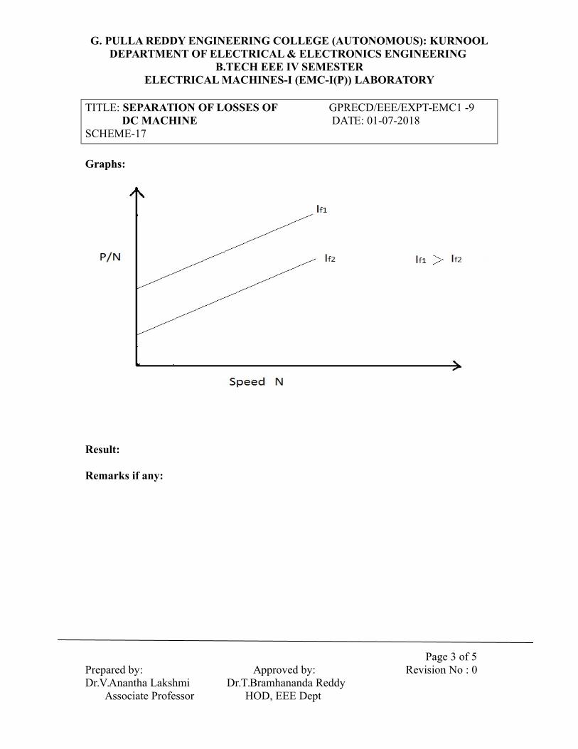
At a given excitation, friction losses and hysterisis are proportional to speed. Windage losses and eddy current losses on the other hand are both proportional to square of speed. Hence, for a given excitation (field current) we have,Friction losses = AN Watts, Windage losses = BN2 WattsHysterisis losses = CN Watts, Eddy current losses = DN2 Watts; Where N = speed.For a motor on no load, power input to the armature is the sum of the armature copper losses and the above losses.In the circuit diagram, power input to the armature = V.Ia watts.Armature copper losses = Ia2.Ra wattsV.Ia – Ia2.Ra = (A + C)N + (B + D)N2
W/N = (A+C) + (B+D)N.The graph between W/N & N is a straight line, from which (A+C) and (B+D) can be found. In order to find A, B, C and D separately, let the field current be changed to a reduced value IIf, and kept constant at that value.
Page 1 of 5
Prepared by: Approved by: Revision No : 0 Dr.V.Anantha Lakshmi Dr.T.Bramhananda Reddy Associate Professor HOD, EEE Dept

G. PULLA REDDY ENGINEERING COLLEGE (AUTONOMOUS): KURNOOLDEPARTMENT OF ELECTRICAL & ELECTRONICS ENGINEERING
B.TECH EEE IV SEMESTERELECTRICAL MACHINES-I (EMC-I(P)) LABORATORY
TITLE: SEPARATION OF LOSSES OF GPRECD/EEE/EXPT-EMC1 -9 DC MACHINE DATE: 01-07-2018 SCHEME-17
If, voltage is applied to the armature as before, we now have W/N = (A+CI) N + (B+D’) N2 (at the reduced excitation, function and windage losses are still are AN and BN2, buthysterisis losses become CIN and eddy current losses become DI N2). We can now obtain(A+C) and (B+D) as before.Now, C/CI = (flux at normal excitation/flux at reduced excitation), andD/DI = (flux at normal excitation/flux at reduced excitation)So, if we determine the ratio (flux at normal excitation/flux at reduced excitation) we can findA, B, C, D, CI, & DI.
Procedure:
1. The circuit is connected as shown in the figure.2. The armature circuit rheostat is kept in maximum position before switching on the
supply.3. Motor is started with the help of a starter by keeping field rheostat in minimum
position.4. Field Rheostat is adjusted to get the field current If to its normal value or values at
which losses are desired.5. By varying armature rheostat, values of current, speed and voltage are noted.6. Field current is kept constant while varying the armature rheostat.7. Field rheostat is gradually decreased and is adjusted to another constant value of
field current and above steps are repeated.8. Graphs are plotted and losses are calculated.
Observations:
If (A) IL (A) IA (A)= IL- If V (v) P=V IL Speed(N) (rpm)
P/N
Page 2 of 5
Prepared by: Approved by: Revision No : 0 Dr.V.Anantha Lakshmi Dr.T.Bramhananda Reddy Associate Professor HOD, EEE Dept
G. PULLA REDDY ENGINEERING COLLEGE (AUTONOMOUS): KURNOOLDEPARTMENT OF ELECTRICAL & ELECTRONICS ENGINEERING
B.TECH EEE IV SEMESTERELECTRICAL MACHINES-I (EMC-I(P)) LABORATORY
TITLE: SEPARATION OF LOSSES OF GPRECD/EEE/EXPT-EMC1 -9 DC MACHINE DATE: 01-07-2018 SCHEME-17
Graphs:
Result:
Remarks if any:
Page 3 of 5
Prepared by: Approved by: Revision No : 0 Dr.V.Anantha Lakshmi Dr.T.Bramhananda Reddy Associate Professor HOD, EEE Dept
G. PULLA REDDY ENGINEERING COLLEGE (AUTONOMOUS): KURNOOLDEPARTMENT OF ELECTRICAL & ELECTRONICS ENGINEERING
B.TECH EEE IV SEMESTERELECTRICAL MACHINES-I (EMC-I(P)) LABORATORY
TITLE: SEPARATION OF LOSSES OF GPRECD/EEE/EXPT-EMC1 -9 DC MACHINE DATE: 01-07-2018 SCHEME-17
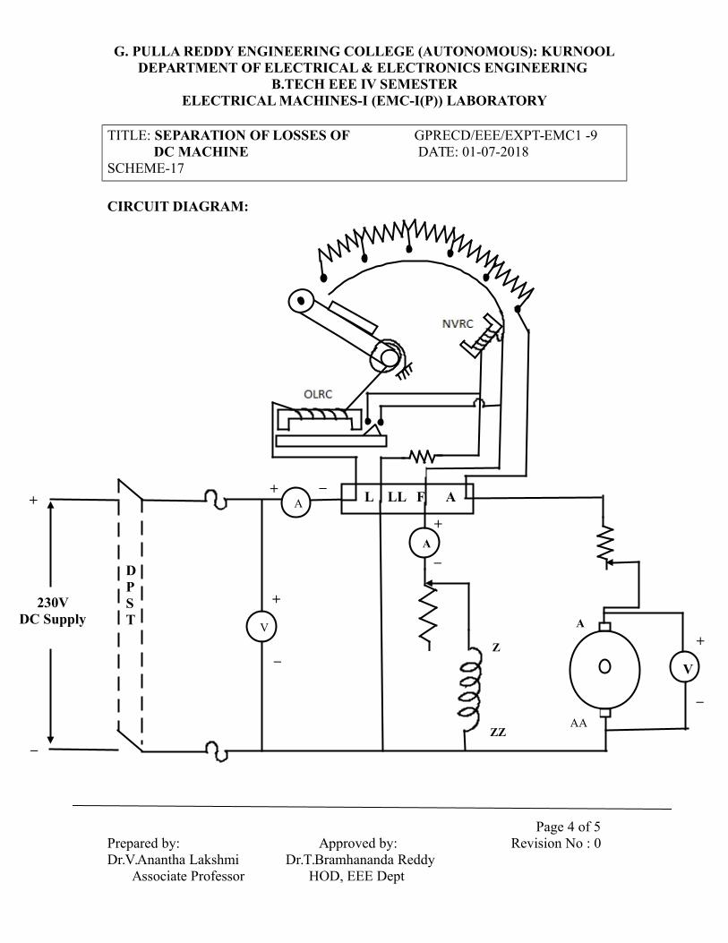
CIRCUIT DIAGRAM:
Page 4 of 5
Prepared by: Approved by: Revision No : 0 Dr.V.Anantha Lakshmi Dr.T.Bramhananda Reddy Associate Professor HOD, EEE Dept
+
_
230VDC Supply
+
_
DPST
_+
V
+
_Z
ZZ
A
AA
V
L LL F AA
A
+
_

G. PULLA REDDY ENGINEERING COLLEGE (AUTONOMOUS): KURNOOLDEPARTMENT OF ELECTRICAL & ELECTRONICS ENGINEERING
B.TECH EEE IV SEMESTERELECTRICAL MACHINES-I (EMC-I(P)) LABORATORY
TITLE: SEPARATION OF LOSSES OF GPRECD/EEE/EXPT-EMC1 -9 DC MACHINE DATE: 01-07-2018 SCHEME-17
Viva Questions:
1. What do you mean by core loss in dc machine?
2. What are the parameters that influence the core losses of a dc machine?
3. Why do we call core loss as constant losses?
4. Explain why copper losses are called as variable losses?
5. What is the condition for maximum efficiency in dc machines?
Page 5 of 5
Prepared by: Approved by: Revision No : 0 Dr.V.Anantha Lakshmi Dr.T.Bramhananda Reddy Associate Professor HOD, EEE Dept

G.PULLA REDDY ENGINEERING COLLEGE (AUTONOMOUS): KURNOOLDEPARTMENT OF ELECTRICAL & ELECTRONICS ENGINEERING
B.TECH EEE IV SEMESTERELECTRICAL MACHINES-I (EMC-I(P)) LABORATORY
TITLE: LOAD TEST ON GPRECD/EEE/EXPT-EMC1 -10 DC COMPOUND GENERATOR DATE: 01-07-2018 SCHEME-17
Objective:To conduct load test on DC compound generator and to draw the external and
internal characteristics of DC compound generator.
Apparatus:
DC Compound Motor-Generator Set, Voltmeters, Ammeters, Tachometer, Resistive Load,Required number of connecting wires
Name plate details:
Fuse ratings:
Theory:
A Compound generator consists of a series field winding and a shunt Field winding. It isfurther categorized into (a) cumulatively compound generator (b) DifferentiallyCompounded generator.Cumulatively Compound generator: In this generator, the flux produced by both fieldWindings adds up together. Hence, the net flux will be increased as the load on theGenerator increases. The emf generated and hence, the terminal voltage increases withload till the series field is saturated. The terminal voltage decreases further Increase in theload current due to the armature reaction. Thus, the cumulatively Compounded Generatoris categorized as (a) Flat- Compounded (b) Over Compounded and (c) UnderCompounded based on the emf generated from No load to rated-load.Differentially Compounded Generator: In this generator, the flux produced by both Fieldwindings opposes each other. Hence, the net flux in the air gap decreases and thegenerated emf decreases with the increase in the load.The graph between VL and IL is the External characteristic of the motor.The graph between E and Ia is the Internal characteristic of the motor.
Page 1 of 7
Prepared by: Approved by: Revision No: 0 Dr.V.Anantha Lakshmi Dr.T.Bramhananda Reddy Associate Professor HOD,EEE Dept

G.PULLA REDDY ENGINEERING COLLEGE (AUTONOMOUS): KURNOOLDEPARTMENT OF ELECTRICAL & ELECTRONICS ENGINEERING
B.TECH EEE IV SEMESTERELECTRICAL MACHINES-I (EMC-I(P)) LABORATORY
TITLE: LOAD TEST ON GPRECD/EEE/EXPT-EMC1 -10 DC COMPOUND GENERATOR DATE: 01-07-2018 SCHEME-17
Procedure:
1. Connections are made as per the circuit diagram.2. After connecting the circuit, the motor field rheostat is kept at minimum position
and generator field rheostat is kept at maximum position.3. The generator is driven at its rated speed with the help of prime mover (DC motor).4. The generator field excitation is adjusted to get the rated terminal voltage on open
circuit.5. A resistive load is connected as shown in figure through a 2-pole switch fuse and the
generator is loaded gradually upto full load.6. The field current of the generator is kept constant by adjusting the generator
rheostat.7. The speed of the motor is checked for different loads and it is kept constant by
adjusting the motor rheostat.8. The terminal voltage and shunt field current are noted for various loads.
Observations:
Cumulative Compound Generator:If(A) IL(A) Ia = IL+ If Vt (v) Eg= Vt +Ia (Ra+Rse)
Differential Compound Generator:If (A) IL (A) Ia = IL+ If Vt (v) Eg= Vt +Ia (Ra+Rse)
Sample Calculations:
Page 2 of 7
Prepared by: Approved by: Revision No: 0 Dr.V.Anantha Lakshmi Dr.T.Bramhananda Reddy Associate Professor HOD,EEE Dept

G.PULLA REDDY ENGINEERING COLLEGE (AUTONOMOUS): KURNOOLDEPARTMENT OF ELECTRICAL & ELECTRONICS ENGINEERING
B.TECH EEE IV SEMESTERELECTRICAL MACHINES-I (EMC-I(P)) LABORATORY
TITLE: LOAD TEST ON GPRECD/EEE/EXPT-EMC1 -10 DC COMPOUND GENERATOR DATE: 01-07-2018 SCHEME-17
For Cumulative Compound:Armature Resistance (Ra) = ΩSeries field Resistance (Rse) = ΩField Current (If) = ALoad current (IL) = AArmature current (Ia) = IL+ If ATerminal Voltage (Vt)= VGenerated Voltage (Eg) = Vt +Ia (Ra+Rse)V
For Differential Compound: Armature Resistance (Ra) = ΩSeries field Resistance (Rse) = ΩField Current (If) = ALoad current (IL) = AArmature current (Ia) = IL+ If ATerminal Voltage (Vt)= VGenerated Voltage (Eg) = Vt +Ia (Ra+Rse)V
Page 3 of 7
Prepared by: Approved by: Revision No: 0 Dr.V.Anantha Lakshmi Dr.T.Bramhananda Reddy Associate Professor HOD,EEE Dept

G.PULLA REDDY ENGINEERING COLLEGE (AUTONOMOUS): KURNOOLDEPARTMENT OF ELECTRICAL & ELECTRONICS ENGINEERING
B.TECH EEE IV SEMESTERELECTRICAL MACHINES-I (EMC-I(P)) LABORATORY
TITLE: LOAD TEST ON GPRECD/EEE/EXPT-EMC1 -10 DC COMPOUND GENERATOR DATE: 01-07-2018 SCHEME-17
Graphs:
Result:
Remarks if any:
Page 4 of 7
Prepared by: Approved by: Revision No: 0 Dr.V.Anantha Lakshmi Dr.T.Bramhananda Reddy Associate Professor HOD,EEE Dept

G.PULLA REDDY ENGINEERING COLLEGE (AUTONOMOUS): KURNOOLDEPARTMENT OF ELECTRICAL & ELECTRONICS ENGINEERING
B.TECH EEE IV SEMESTERELECTRICAL MACHINES-I (EMC-I(P)) LABORATORY
TITLE: LOAD TEST ON GPRECD/EEE/EXPT-EMC1 -10 DC COMPOUND GENERATOR DATE: 01-07-2018 SCHEME-17
CIRCUIT DIAGRAM:
DC Cumulative Compound Generator
Page 5 of 7
Prepared by: Approved by: Revision No: 0 Dr.V.Anantha Lakshmi Dr.T.Bramhananda Reddy Associate Professor HOD,EEE Dept
If
AA
YA A
+
_
V
_+
+
_
DPST
Z
L LL F A
230V DC Supply
LOAD
+ _
Z
IL
A
ZZ
ZZAA
AYY
350Ω1.1A
350Ω1.1A

G.PULLA REDDY ENGINEERING COLLEGE (AUTONOMOUS): KURNOOLDEPARTMENT OF ELECTRICAL & ELECTRONICS ENGINEERING
B.TECH EEE IV SEMESTERELECTRICAL MACHINES-I (EMC-I(P)) LABORATORY
TITLE: LOAD TEST ON GPRECD/EEE/EXPT-EMC1 -10 DC COMPOUND GENERATOR DATE: 01-07-2018 SCHEME-17
DC Differential Compound Generator
Page 6 of 7
Prepared by: Approved by: Revision No: 0 Dr.V.Anantha Lakshmi Dr.T.Bramhananda Reddy Associate Professor HOD,EEE Dept
If
AA
YYA A
+
_
V
_+
+
_
DPST
Z
L LL F A
230V DC Supply
LOAD
+ _
Z
IL
A
ZZ
ZZAAAA
AY
350Ω1.1A
350Ω1.1A

G.PULLA REDDY ENGINEERING COLLEGE (AUTONOMOUS): KURNOOLDEPARTMENT OF ELECTRICAL & ELECTRONICS ENGINEERING
B.TECH EEE IV SEMESTERELECTRICAL MACHINES-I (EMC-I(P)) LABORATORY
TITLE: LOAD TEST ON GPRECD/EEE/EXPT-EMC1 -10 DC COMPOUND GENERATOR DATE: 01-07-2018 SCHEME-17
Viva Questions:
1. What happens to induced emf when the compound machine is operated as
cumulative compounding when the load is increased?
2. Which winding in compound generator is having large area of cross section of the
copper and Why?
3. Explain why the commutator is used in dc machines?
4. What is the difference between the 3-point and 4-point starter?
5. What is armature reaction in dc machines?
6. How do you compensate the armature reaction in dc machines?
7. Why do we take the field rheostat in minimum position in the case of motor
operation and it is in maximum position in the case of generator action?
Page 7 of 7
Prepared by: Approved by: Revision No: 0 Dr.V.Anantha Lakshmi Dr.T.Bramhananda Reddy Associate Professor HOD,EEE Dept
G.PULLA REDDY ENGINEERING COLLEGE (AUTONOMOUS): KURNOOLDEPARTMENT OF ELECTRICAL & ELECTRONICS ENGINEERING
B.TECH EEE IV SEMESTERELECTRICAL MACHINES-I (EMC-I(P)) LABORATORY
TITLE: OC, SC TESTS ON GPRECD/EEE/EXPT-EMC1 -11 1- TRANSFORMER SCHEME-17 DATE: 01-07-2018
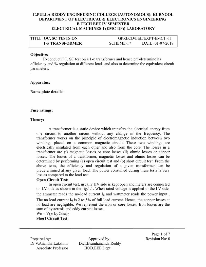
Objective:To conduct OC, SC test on a 1-φ transformer and hence pre-determine its
efficiency and % regulation at different loads and also to determine the equivalent circuit parameters..
Apparatus:
Name plate details:
Fuse ratings:
Theory:
A transformer is a static device which transfers the electrical energy fromone circuit to another circuit without any change in the frequency. Thetransformer works on the principle of electromagnetic induction between twowindings placed on a common magnetic circuit. These two windings areelectrically insulated from each other and also from the core. The losses in atransformer are (i) magnetic losses or core losses (ii) ohmic losses or copperlosses. The losses of a transformer, magnetic losses and ohmic losses can bedetermined by performing (a) open circuit test and (b) short circuit test. From theabove tests, the efficiency and regulation of a given transformer can bepredetermined at any given load. The power consumed during these tests is veryless as compared to the load test.Open Circuit Test:
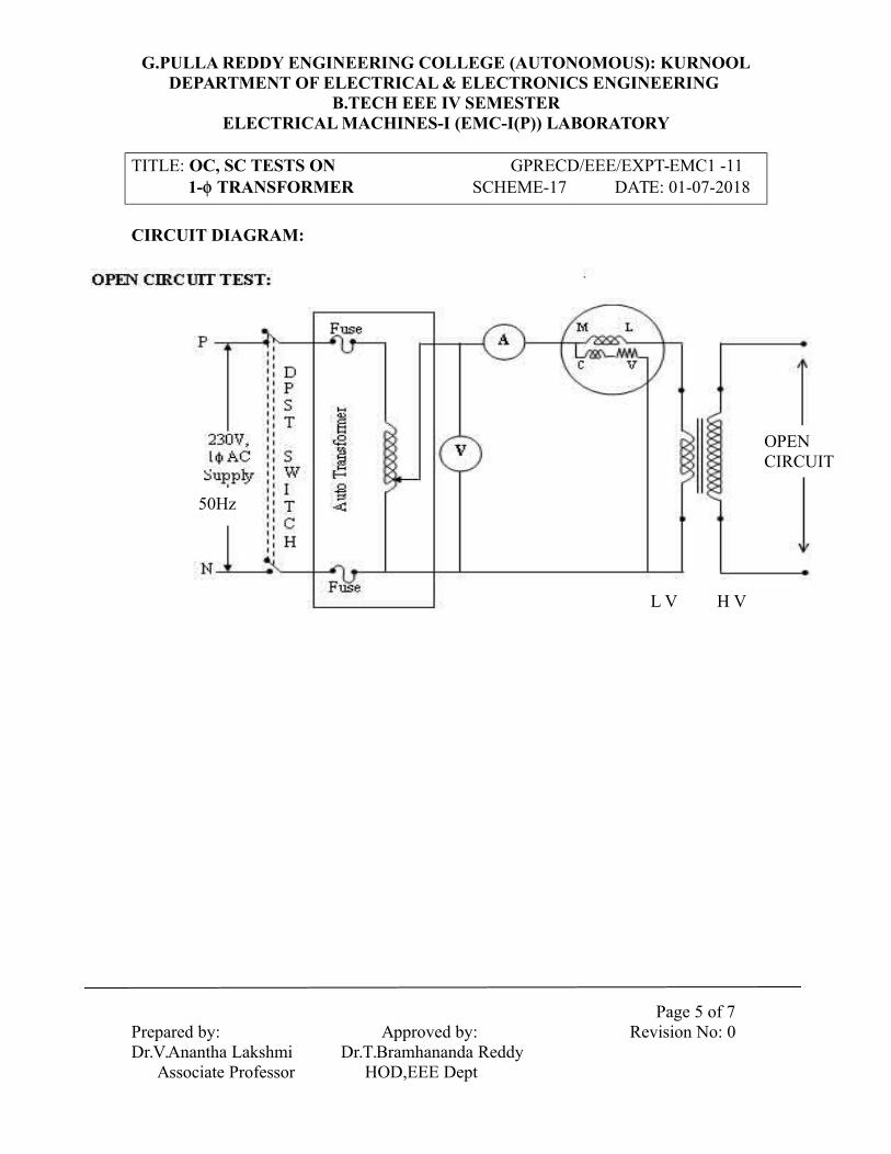
In open circuit test, usually HV side is kept open and meters are connectedon LV side as shown in the fig.1.1. When rated voltage is applied to the LV side,the ammeter reads the no-load current Io and wattmeter reads the power input .
The no load current I0 is 2 to 5% of full load current. Hence, the copper losses atno-load are negligible. We represent the iron or core losses. Iron losses are thesum of hysteresis and eddy current losses.Wo = VLV IO Cosф0Short Circuit Test:
Page 1 of 7
Prepared by: Approved by: Revision No: 0 Dr.V.Anantha Lakshmi Dr.T.Bramhananda Reddy Associate Professor HOD,EEE Dept

G.PULLA REDDY ENGINEERING COLLEGE (AUTONOMOUS): KURNOOLDEPARTMENT OF ELECTRICAL & ELECTRONICS ENGINEERING
B.TECH EEE IV SEMESTERELECTRICAL MACHINES-I (EMC-I(P)) LABORATORY
TITLE: OC, SC TESTS ON GPRECD/EEE/EXPT-EMC1 -11 1- TRANSFORMER SCHEME-17 DATE: 01-07-2018
This test is performed to determine the equivalent resistance and leakagereactance of the transformer and copper losses at full – load condition. In this testusually LV side is shorted and meters are connected on HV side. A variable lowvoltage is applied to the HV winding with the help of an auto-transformer. Thisvoltage is varied till the rated current flows in the HV side or LV side. The voltageapplied is 5 to 10 percent of rated voltage, while the rated current flows in thewindings. The wattmeter indicates the full load copper losses and core losses atVSC But the iron, losses at this low voltage are negligible as compared to the ironlosses at the rated voltage
Procedure:
O.C.TEST:1) Connect the circuit as per the circuit diagram.2) Rated voltage is applied to circuit on Low Voltage side
with the help of Auto Transformer with High Voltage side open.
3) All Meter readings are taken.S.C. TEST:
1) Connect the circuit as per the circuit diagram.2) Rated current is applied to circuit on High Voltage side
with the help of Booster Transformer with Low Voltage side short-circuited.
3) All meter readings are taken.
Observations:
O.C. Test:S.No Input Voltage (V0) No load current (I0) Power (o/p) Wo
S.C.TEST:
S.No Voltage (VSC) Rated current (ISC) Power (o/p) Wsc
Page 2 of 7
Prepared by: Approved by: Revision No: 0 Dr.V.Anantha Lakshmi Dr.T.Bramhananda Reddy Associate Professor HOD,EEE Dept

G.PULLA REDDY ENGINEERING COLLEGE (AUTONOMOUS): KURNOOLDEPARTMENT OF ELECTRICAL & ELECTRONICS ENGINEERING
B.TECH EEE IV SEMESTERELECTRICAL MACHINES-I (EMC-I(P)) LABORATORY
TITLE: OC, SC TESTS ON GPRECD/EEE/EXPT-EMC1 -11 1- TRANSFORMER SCHEME-17 DATE: 01-07-2018
Efficiency Table:Cos Φ 0.3 0.4 0.6 0.8 1Load
Regulation Table:Cos Φ 0.3 0.4 0.6 0.8 1Load Lead Lag Lead Lag Lead Lag Lead Lag Lead Lag
GRAPHS:
SAMPLE CALCULATIONS:
Calculation of Ro and Xo of equivalent circuit fromO.C test V0 = V, I0 = A , W0 = WattsIron losses = W0 = V0 I0 cosф0Cos ф0 = W0 /V0I0Cos ф0 =, sin ф0 =
Im = I0Sin ф0, Iw = I0Cos ф0
LV SIDE: R0 = V0 / Iw , X0= V0 / Im ,
Page 3 of 7
Prepared by: Approved by: Revision No: 0 Dr.V.Anantha Lakshmi Dr.T.Bramhananda Reddy Associate Professor HOD,EEE Dept

G.PULLA REDDY ENGINEERING COLLEGE (AUTONOMOUS): KURNOOLDEPARTMENT OF ELECTRICAL & ELECTRONICS ENGINEERING
B.TECH EEE IV SEMESTERELECTRICAL MACHINES-I (EMC-I(P)) LABORATORY
TITLE: OC, SC TESTS ON GPRECD/EEE/EXPT-EMC1 -11 1- TRANSFORMER SCHEME-17 DATE: 01-07-2018
HV Side: HV side R0 = : LV side R0 x K² = ; HV side X0 = : LV side X0 x K² =Where K = Turns ratio
SC TEST:Calculation of R01 and X01 for equivalent circuitIsc = A , VSC = V , Wsc = WattsFull load copper losses or variable losses = Wsc = I²sc R02
R02 = Wsc / I2
sc, Z02 = Vsc/Isc, X02 = √(Z202 –R2
02)
R01 = R02 x K2 = Req, X01 = X02 x K2 = Xeq, I’2 = I2 /K, V’2 = V2 x K
Calculation of percent regulation from SC test (%Voltage Regulation)
At full load current, I2 = A, V2 = V, p.f = CosΦ= 0. 8 lag Percent regulation (%V.R) = (I2 R02CosΦ ± I2X02SinΦ)/ V2 (Note: + for lagging and – for leading power factors)
Efficiency Calculation from O.C and S.C tests
%ŋ = (XV2I2CosΦ)/( XV2I2CosΦ+Iron losses (W0 ) + Copper losses at load X (X2Wsc))
At full load 0.8 power factor where X = load (varies from 0 to 1)
RESULT:REMARKS IF ANY:
Page 4 of 7
Prepared by: Approved by: Revision No: 0 Dr.V.Anantha Lakshmi Dr.T.Bramhananda Reddy Associate Professor HOD,EEE Dept
G.PULLA REDDY ENGINEERING COLLEGE (AUTONOMOUS): KURNOOLDEPARTMENT OF ELECTRICAL & ELECTRONICS ENGINEERING
B.TECH EEE IV SEMESTERELECTRICAL MACHINES-I (EMC-I(P)) LABORATORY
TITLE: OC, SC TESTS ON GPRECD/EEE/EXPT-EMC1 -11 1- TRANSFORMER SCHEME-17 DATE: 01-07-2018
CIRCUIT DIAGRAM:
Page 5 of 7
Prepared by: Approved by: Revision No: 0 Dr.V.Anantha Lakshmi Dr.T.Bramhananda Reddy Associate Professor HOD,EEE Dept
OPEN CIRCUIT
H VL V
50Hz
H V
OPEN CIRCUIT

G.PULLA REDDY ENGINEERING COLLEGE (AUTONOMOUS): KURNOOLDEPARTMENT OF ELECTRICAL & ELECTRONICS ENGINEERING
B.TECH EEE IV SEMESTERELECTRICAL MACHINES-I (EMC-I(P)) LABORATORY
TITLE: OC, SC TESTS ON GPRECD/EEE/EXPT-EMC1 -11 1- TRANSFORMER SCHEME-17 DATE: 01-07-2018
CIRCUIT DIAGRAM:
SHORT CIRCUIT TEST:
Page 6 of 7
Prepared by: Approved by: Revision No: 0 Dr.V.Anantha Lakshmi Dr.T.Bramhananda Reddy Associate Professor HOD,EEE Dept

G.PULLA REDDY ENGINEERING COLLEGE (AUTONOMOUS): KURNOOLDEPARTMENT OF ELECTRICAL & ELECTRONICS ENGINEERING
B.TECH EEE IV SEMESTERELECTRICAL MACHINES-I (EMC-I(P)) LABORATORY
TITLE: OC, SC TESTS ON GPRECD/EEE/EXPT-EMC1 -11 1- TRANSFORMER SCHEME-17 DATE: 01-07-2018
Viva Questions:
1. In OC test power supply is connected to low voltage side but in SC test
power supply is connected to high voltage side of the transformer.
Why?2. How we will find (or) Identify the L.V winding and H.V winding of the
transformer just by observing the outer part of the transformer.[Here
we don’t know number of turns]3. Why R1, X1 and R0,Xm in equivalent circuit of transformer are called
as linear parameters and non linear parameters?4. Why we are connecting R1, X1 and R0,Xm in respective positions?
Can’t we interchange?5. Why we are conducting OC test at rated voltage and SC test at rated
current? What will happen if we conduct tests other than that rated
voltages.6. What is magnetic inrush current in transformer?
Page 7 of 7
Prepared by: Approved by: Revision No: 0 Dr.V.Anantha Lakshmi Dr.T.Bramhananda Reddy Associate Professor HOD,EEE Dept

G.PULLA REDDY ENGINEERING COLLEGE (AUTONOMOUS): KURNOOLDEPARTMENT OF ELECTRICAL & ELECTRONICS ENGINEERING
B.TECH EEE IV SEMESTERELECTRICAL MACHINES-I (EMC-I(P)) LABORATORY
TITLE: SUMPNER’S (OR) BACK TO GPRECD/EEE/EXPT-EMC1 -12 BACK TEST ON TWO IDENTICAL SCHEME-17 DATE: 01-07-2018 1- TRANSFORMERS
Objective:To perform Sumpner’s test on two identical single phase transformers and find the
efficiency and percentage regulation under load conditions.Apparatus:
Name plate details:
Fuse ratings:
Theory:
The efficiency of a transformer can be predetermined by conducting O/\.C andS.C. tests. But the rise in temperature and its effect on parameters can be foundonly by conducting the actual load test. It is difficult to conduct the actual loadtest for large transformers. Instead Sumpner’s test is helpful in determining theefficiency, regulation and also effect of rise in temperature on transformerparameters can be obtained with small amount of power consumption. InSumpner's test, the two primary windings of the identical transformers areconnected in parallel across the supply and the two secondary’s are connected inseries with their polarities in opposition. One wattmeter (L.P.F. type), onevoltmeter and one ammeter are connected at primary side. One wattmeter (U.P.F:type), one voltmeter and one ammeter are connected at secondary side. Ifprimaries are energized then the voltage across the two secondary windings willbe zero since both the transformers are identical transformers. The power input tothe transformers at no-load is indicated by the wattmeter on the primary side. Thispower is, equal-to the iron losses of the two transformers. An auto-transformer isconnected in series with the two secondary windings. A small voltage is injectedin the secondary circuit from a separate ac source. It will circulate a current in thesecondary side since the secondaries are in opposition, the secondary current willcause primary current in opposite directions so that the reading of wattmeter onprimary is not affected and it will indicate the iron losses of the two transformers.
Page 1 of 6
Prepared by: Approved by: Revision No: 0 Dr.V.Anantha Lakshmi Dr.T.Bramhananda Reddy Associate Professor HOD,EEE Dept

G.PULLA REDDY ENGINEERING COLLEGE (AUTONOMOUS): KURNOOLDEPARTMENT OF ELECTRICAL & ELECTRONICS ENGINEERING
B.TECH EEE IV SEMESTERELECTRICAL MACHINES-I (EMC-I(P)) LABORATORY
TITLE: SUMPNER’S (OR) BACK TO GPRECD/EEE/EXPT-EMC1 -12 BACK TEST ON TWO IDENTICAL SCHEME-17 DATE: 01-07-2018 1- TRANSFORMERS
The auto-transformer is adjusted till the full load current flows in the secondaryside of the transformer. At full load current the wattmeter on the secondary sideindicates the full load copper losses of the two transformers.
Procedure:
1. The circuit is connected as shown in the circuit diagram2. Both the transformers are energized at rated voltages and frequencies.3. With secondaries open, the readings of voltmeter, ammeter and
wattmeter are noted which give the core losses of both the transformers.
4. The secondaries of both the transformer are connected in phase opposition and checked the voltmeter reading across secondaries and if V=0 , close SPST switch.
5. Low voltage is injected in the secondary circuit by means of voltage regulation from the source connected.
6. Injected voltage is adjusted till rated current flows through the series secondaries of the transformers.
7. All the readings are noted.Observations:
V1 I1 W1 V2 I2 W2
Load Total losses Efficiencycos=0.5 cos=0.8
Graphs:
Page 2 of 6
Prepared by: Approved by: Revision No: 0 Dr.V.Anantha Lakshmi Dr.T.Bramhananda Reddy Associate Professor HOD,EEE Dept

G.PULLA REDDY ENGINEERING COLLEGE (AUTONOMOUS): KURNOOLDEPARTMENT OF ELECTRICAL & ELECTRONICS ENGINEERING
B.TECH EEE IV SEMESTERELECTRICAL MACHINES-I (EMC-I(P)) LABORATORY
TITLE: SUMPNER’S (OR) BACK TO GPRECD/EEE/EXPT-EMC1 -12 BACK TEST ON TWO IDENTICAL SCHEME-17 DATE: 01-07-2018 1- TRANSFORMERS
SAMPLE CALCULATIONS:
Page 3 of 6
Prepared by: Approved by: Revision No: 0 Dr.V.Anantha Lakshmi Dr.T.Bramhananda Reddy Associate Professor HOD,EEE Dept

G.PULLA REDDY ENGINEERING COLLEGE (AUTONOMOUS): KURNOOLDEPARTMENT OF ELECTRICAL & ELECTRONICS ENGINEERING
B.TECH EEE IV SEMESTERELECTRICAL MACHINES-I (EMC-I(P)) LABORATORY
TITLE: SUMPNER’S (OR) BACK TO GPRECD/EEE/EXPT-EMC1 -12 BACK TEST ON TWO IDENTICAL SCHEME-17 DATE: 01-07-2018 1- TRANSFORMERS
Formulas for Calculations:
Core loss for each transformer = W1 / 2 = W
Full load copper loss for each transformer = W2 / 2 = W
%ŋ = (XV2I2CosΦ)/( XV2I2CosΦ+Iron losses (W0)+Copper losses at load X
(X2Wsc))
At full load 0.8 power factor where X = load ratio (varies from 0 to 1),
where V2 = Secondary rated voltage, I2 = full load current
Calculation of percent regulation (%Voltage Regulation)
At full load current, I2 = A, V2 = V, p.f = CosΦ= 0. 8 lag
Percent regulation (%V.R) = (I2 R02CosΦ ± I2X02SinΦ)/ V2
(Note: + for lagging and – for leading power factors)
Result:
Page 4 of 6
Prepared by: Approved by: Revision No: 0 Dr.V.Anantha Lakshmi Dr.T.Bramhananda Reddy Associate Professor HOD,EEE Dept

CIRCUIT DIAGRAM:
Viva Questions:
1. What is the main purpose of Sumpner’s test? Explain in detail?2. Why we are using (0-2A), (0-10A) Ammeter especially and why we are
using LPF and UPF wattmeter’s respected places in circuit diagram?
Can’t we interchange?3. What is the basic use of SPST switch in circuit diagram?

4. Zero and maximum voltage rs at what power factor angles? Give the
examples?5. Maximum efficiency occurs at what load? And why it is so?

G.PULLA REDDY ENGINEERING COLLEGE (AUTONOMOUS): KURNOOLDEPARTMENT OF ELECTRICAL & ELECTRONICS ENGINEERING
B.TECH EEE IV SEMESTERELECTRICAL MACHINES-I (EMC-I(P)) LABORATORY
TITLE: SCOTT CONNECTION OF GPRECD/EEE/EXPT-EMC1 -13 TRANSFORMERS SCHEME-17 DATE: 01-07-2018
Objective:To make Scott connection of transformers and to draw characteristics at balanced
and unbalanced loads.
Apparatus:
Name plate details:
Fuse ratings:
Theory:
Scott connection is one by which 3-phase to 2-phase transformation isaccomplished with the help of two identical Transformers having same current rating.One Transformer has a center tap on primary side and it is known as Maintransformer. It forms the horizontal member of the connection. Another Transformerhas 0.866tap on primary side and known as Teaser transformer. The 50% tap point onprimary side of the main Transformer is joined to 86.6% tap on primary of the teaserTransformer. Obviously full rating of the Transformer is not at all used. Refer to thefig. The main Transformer primary winding center tap point D is connected to oneend of the primary of the teaser on secondary side, both the main & teaserTransformer turns are used (not only 86.6%).Hence the voltage per turn will be equalfor both Transformer. Since point D is located midway on AB, VCD leads VAB by 900
i.e, voltages across primary are 900 apart also. Position of Neutral point N on primaryside: Remember point D is not the neutral on primary, since its voltages w.r.t R, Y, Bare not equal to VL/√3 i.e, the neutral point is that one which gives equal voltage withR, Y, B. The neutral point is one third the way down the teaser T/F winding from C toD Or point N divides the teaser primary winding in the ratio of 1:2. Hence the neutralmust be At 86.6/3=28.8% from DThe secondaries of the two transformers gives two phase supply with 900 phase difference. The following figure gives further information about Scott connection.
Page 1 of 8
Prepared by: Approved by: Revision No: 0 Dr.V.Anantha Lakshmi Dr.T.Bramhananda Reddy Associate Professor HOD,EEE Dept
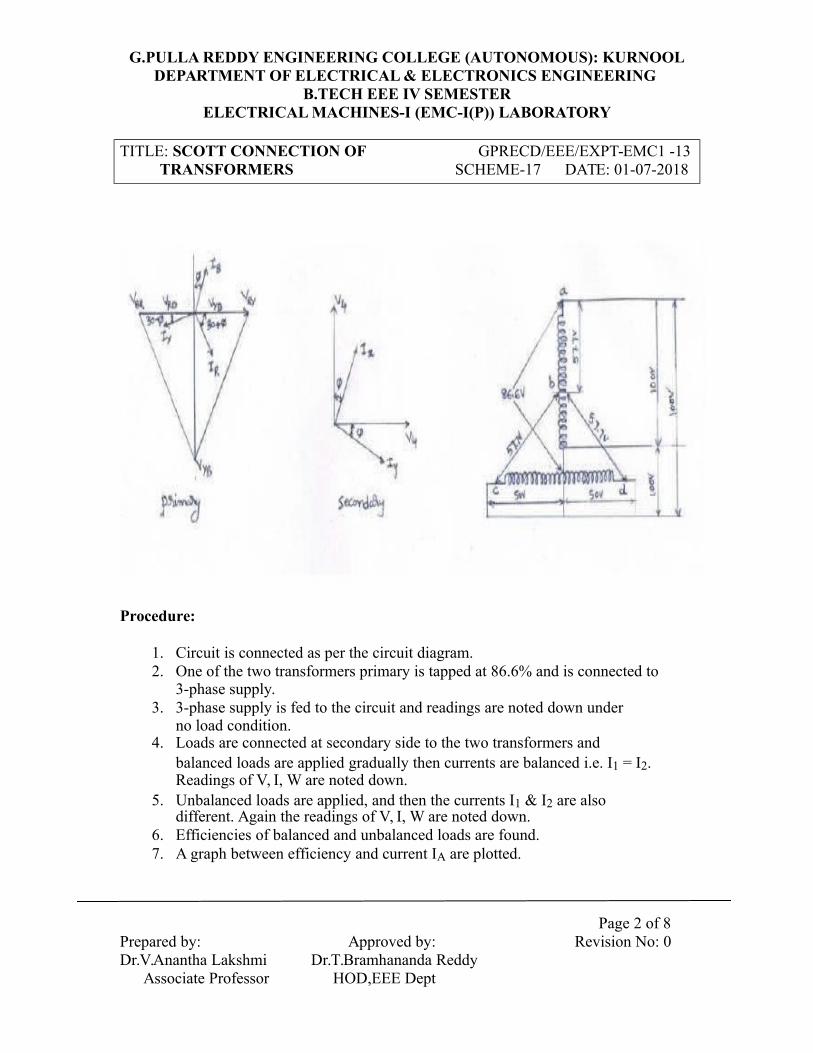
G.PULLA REDDY ENGINEERING COLLEGE (AUTONOMOUS): KURNOOLDEPARTMENT OF ELECTRICAL & ELECTRONICS ENGINEERING
B.TECH EEE IV SEMESTERELECTRICAL MACHINES-I (EMC-I(P)) LABORATORY
TITLE: SCOTT CONNECTION OF GPRECD/EEE/EXPT-EMC1 -13 TRANSFORMERS SCHEME-17 DATE: 01-07-2018
Procedure:
1. Circuit is connected as per the circuit diagram.2. One of the two transformers primary is tapped at 86.6% and is connected to
3-phase supply.3. 3-phase supply is fed to the circuit and readings are noted down under
no load condition.4. Loads are connected at secondary side to the two transformers and
balanced loads are applied gradually then currents are balanced i.e. I1 = I2. Readings of V, I, W are noted down.
5. Unbalanced loads are applied, and then the currents I1 & I2 are also different. Again the readings of V, I, W are noted down.
6. Efficiencies of balanced and unbalanced loads are found.7. A graph between efficiency and current IA are plotted.
Page 2 of 8
Prepared by: Approved by: Revision No: 0 Dr.V.Anantha Lakshmi Dr.T.Bramhananda Reddy Associate Professor HOD,EEE Dept

G.PULLA REDDY ENGINEERING COLLEGE (AUTONOMOUS): KURNOOLDEPARTMENT OF ELECTRICAL & ELECTRONICS ENGINEERING
B.TECH EEE IV SEMESTERELECTRICAL MACHINES-I (EMC-I(P)) LABORATORY
TITLE: SCOTT CONNECTION OF GPRECD/EEE/EXPT-EMC1 -13 TRANSFORMERS SCHEME-17 DATE: 01-07-2018
Observations:
Voltage(V) I/P Power(W1+W2)
IA IB IC V1 I1 V2 I2% η = (V1I1+V2I2)/InputPower (W)
W1 W2 WBalanced LoadsUnbalancedLoads
Page 3 of 8
Prepared by: Approved by: Revision No: 0 Dr.V.Anantha Lakshmi Dr.T.Bramhananda Reddy Associate Professor HOD,EEE Dept
G.PULLA REDDY ENGINEERING COLLEGE (AUTONOMOUS): KURNOOLDEPARTMENT OF ELECTRICAL & ELECTRONICS ENGINEERING
B.TECH EEE IV SEMESTERELECTRICAL MACHINES-I (EMC-I(P)) LABORATORY
TITLE: SCOTT CONNECTION OF GPRECD/EEE/EXPT-EMC1 -13 TRANSFORMERS SCHEME-17 DATE: 01-07-2018
Page 4 of 8
Prepared by: Approved by: Revision No: 0 Dr.V.Anantha Lakshmi Dr.T.Bramhananda Reddy Associate Professor HOD,EEE Dept

Graphs:
SAMPLE CALCULATIONS:
Input Power = W1+W2 = Watts; Output Power = V1I1+V2I2 = Watts Efficiency (η) = (Out Power / Input Power) X 100

Result:
Remarks if any:
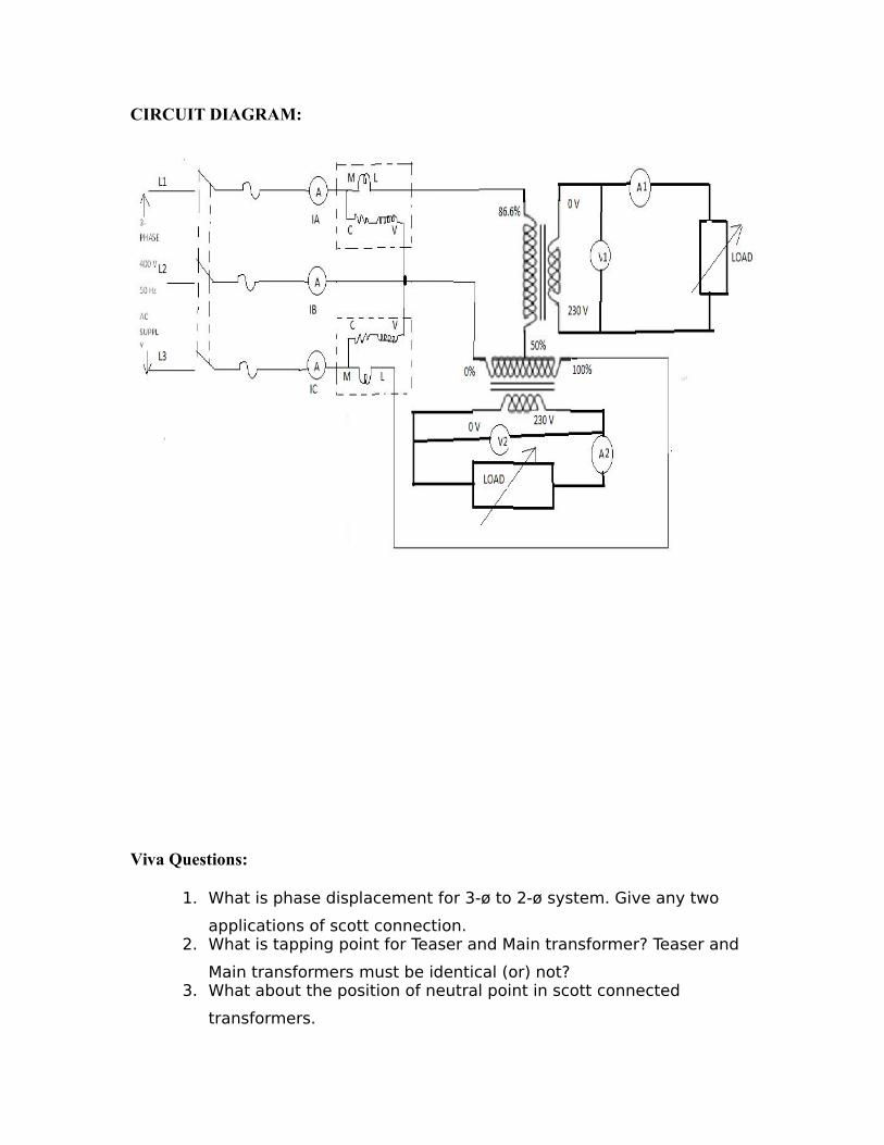
CIRCUIT DIAGRAM:
Viva Questions:
1. What is phase displacement for 3-ø to 2-ø system. Give any two
applications of scott connection.2. What is tapping point for Teaser and Main transformer? Teaser and
Main transformers must be identical (or) not?3. What about the position of neutral point in scott connected
transformers.

4. What about KVA rating of scott- connected transformers?5. Derive the conversion of 3-ø to 2-ø by the vector diagram?

G.PULLA REDDY ENGINEERING COLLEGE (AUTONOMOUS): KURNOOLDEPARTMENT OF ELECTRICAL & ELECTRONICS ENGINEERING
B.TECH EEE IV SEMESTERELECTRICAL MACHINES-I (EMC-I(P)) LABORATORY
TITLE: SEPARATION OF CORE GPRECD/EEE/EXPT-EMC1 -14 LOSSES OF A 1- TRANSFORMER SCHEME-17 DATE: 01-07-2018
Objective:To separate the iron losses of a single-phase transformer i.e. hysteresis and eddy
current losses.Apparatus:
Name plate details:
Fuse ratings:
Theory:
There are mainly two types of losses in a transformer. i.e. Core loss (Ironlosses)and Ohmic (Copper) losses. Core loss mainly depends on frequency andmaximum flux density when the volume and thickness of core laminations aregiven.Hysteresis and eddy current losses are called iron losses and takes place in thecore of the transformer. i.e. Pc = Ph + Pe. Also it is known that Ph = KhfBxm andPe = Kef
2B2m
Kh is proportionality constant that de[ends upon the volume and quality of the material. Ke is proportionality constant that depends upon the volume, resistivity of the core materials, thickness of the laminations and the units employed.Eddy current loses also depends on the frequency f is given by We = KB2 max f2 t2 = Bf2
Where Bmax = Maximum flux density in the core weber/m2
f = Frequency (cycles / seconds) in HzThe iron losses will be expressed by
PC = Ph + Pe = KhfBxm + Kef2B2
m =Af + Bf2
Pc/f = A + BfThis is a equation of straight line y=mx+c, when y=Pc/f, C=A and M=B Eddy current & hysteresis losses can be separated when A&B are foundThe variable frequency supply is obtained from an alternator when frequency can be varied.
Page 1 of 5
Prepared by: Approved by: Revision No: 0 Dr.V.Anantha Lakshmi Dr.T.Bramhananda Reddy Associate Professor HOD,EEE Dept

G.PULLA REDDY ENGINEERING COLLEGE (AUTONOMOUS): KURNOOLDEPARTMENT OF ELECTRICAL & ELECTRONICS ENGINEERING
B.TECH EEE IV SEMESTERELECTRICAL MACHINES-I (EMC-I(P)) LABORATORY
TITLE: SEPARATION OF CORE GPRECD/EEE/EXPT-EMC1 -14 LOSSES OF A 1- TRANSFORMER SCHEME-17 DATE: 01-07-2018
Procedure:
1. Connections are made as per the circuit diagram.2. Supply is given to the transformer from the alternator.3. The field rheostat of the alternator is varied till the rated voltage of the
transformer is obtained.4. Frequency is varied by running the alternator at different speeds.5. To make the transformer induction constant the voltage should be
proportional to the variable frequency.6. Hence, by maintaining V/f constant, the readings of the voltmeter,
ammeter, wattmeter and speed of the alternator are taken.Observations:
Speed (N) Voltage Current I Power W Frequency V/f W/frpm V volts Amp Watts f= pN/120
Graphs:
Page 2 of 5
Prepared by: Approved by: Revision No: 0 Dr.V.Anantha Lakshmi Dr.T.Bramhananda Reddy Associate Professor HOD,EEE Dept

G.PULLA REDDY ENGINEERING COLLEGE (AUTONOMOUS): KURNOOLDEPARTMENT OF ELECTRICAL & ELECTRONICS ENGINEERING
B.TECH EEE IV SEMESTERELECTRICAL MACHINES-I (EMC-I(P)) LABORATORY
TITLE: SEPARATION OF CORE GPRECD/EEE/EXPT-EMC1 -14 LOSSES OF A 1- TRANSFORMER SCHEME-17 DATE: 01-07-2018
SAMPLE CALCULATIONS:
From the graphK1 =A = C=K2=m= B= y/x = slope of the line=
Therefore Ph= Af; Pe = Bf2
For a frequency of 50 Hz then Ph = ; Pe =
Result:
Remarks if any:
Page 3 of 5
Prepared by: Approved by: Revision No: 0 Dr.V.Anantha Lakshmi Dr.T.Bramhananda Reddy Associate Professor HOD,EEE Dept

CIRCUIT DIAGRAM:
Viva Questions:
1. What are the conditions to perform the test separation of losses.
Why?2. If the thickness of laminations is reduced in a transformer what will
be effect on core loss?3. Transformer designed to operate at 50Hz is operated at rated
voltage and 60Hz. How it will change core loss of transformer?

4. What will happen in core loss if a part of transformer core is
replaced by a wood?5. What are the assumptions made for ideal transformer?

G.PULLA REDDY ENGINEERING COLLEGE (AUTONOMOUS): KURNOOLDEPARTMENT OF ELECTRICAL & ELECTRONICS ENGINEERING
B.TECH EEE IV SEMESTERELECTRICAL MACHINES-I (EMC-I(P)) LABORATORY
TITLE: LOAD TEST ON GPRECD/EEE/EXPT-EMC1 -15 1- TRANSFORMER SCHEME-17 DATE: 01-07-2018
Objective:To determine the efficiency and regulation of a single phase transformer by
conducting load test.
Apparatus:
Name plate details:
Fuse ratings:
Theory:
Load Test: A transformer is a static device which transfers the electrical energy from onecircuit to another circuit without any change in the frequency. The transformer works onthe principle of electromagnetic induction between two windings placed on a commonmagnetic circuit. These two windings are electrically insulated from each other and alsofrom the core. The efficiency of the transformer can be determined in different ways i.e.by using O.C and S.C. Tests (indirect method) and also Sumpners test. Direct loading(Load Test) can also be conducted on Transformer. This load test is performed todetermine the efficiency and regulation of a transformer at different load conditions.Usually, this test is performed for low, power, rating of transformers. This test givesaccurate results as compared to the above tests. In this test, measurements are taken on
HV side and LV side at different load conditions. WLV indicates the input power at LV
side and V2xI2 indicates the output power connected on secondary side (HV). The powerconsumed during this test is very large as compared to the OC and SC tests and is a majordisadvantage for this test.Procedure:
LOAD TEST:1) Connect the circuit as shown in the circuit diagram.2) Rated voltage is applied to the transformer.3) All the readings of voltmeters, ammeters & wattmeter’s are
noted.
Page 1 of 4
Prepared by: Approved by: Revision No: 0 Dr.V.Anantha Lakshmi Dr.T.Bramhananda Reddy Associate Professor HOD,EEE Dept

G.PULLA REDDY ENGINEERING COLLEGE (AUTONOMOUS): KURNOOLDEPARTMENT OF ELECTRICAL & ELECTRONICS ENGINEERING
B.TECH EEE IV SEMESTERELECTRICAL MACHINES-I (EMC-I(P)) LABORATORY
TITLE: LOAD TEST ON GPRECD/EEE/EXPT-EMC1 -15 1- TRANSFORMER SCHEME-17 DATE: 01-07-2018
4) Load is increased in steps by maintaining V1 constant,till the secondary rated current is obtained.
Observations:
LOAD TEST:
V1 V2 I1 I2 Input Power(WLV) Output Power(V2I2) %= % Regulation =V V A A Watts (W) Watts(W) V2I2/ WLV (V20-V2) / V20
V20= No load terminal voltage of secondary of the transformer.
Graphs:
SAMPLE CALCULATIONS:
Input Power (WLV) = Watts ; Output power (V2I2) = Watts% Efficiency (η) = (Output Power/Input Power) X 100
Result:
Remarks if any
Page 2 of 4
Prepared by: Approved by: Revision No: 0 Dr.V.Anantha Lakshmi Dr.T.Bramhananda Reddy Associate Professor HOD,EEE Dept

CIRCUIT DIAGRAM:
Viva Questions:
1. Why the core of a transformer is assembled with laminated sheets?
2. What materials are used for construction of core?
3. At what condition the maximum efficiency of a transformer occurs?
4. Calculate the efficiency of the transformer set under test for 0.85 p.f with (i) full
load (ii) half full load (iii) one fourth full load?

5. State the losses occurring in a transformer at no load nd on load and on what
factors these depend?
6. Why iron losses are not considered in short circuit calculation?

Electrical Machines-I Lab (Scheme-2017
List of experiments
1. Open circuit characteristic (OCC) of DC shunt generator.
2. Brake test on DC compound motor
3. a) Swinburne’s test on DC shunt Machine.
b) Speed control of DC shunt motor.
4. Hopkinson’s test.
5. Field’s test.
6. a) OC, SC Test on 1-phase transformer.
b) Load test on single phase transformer.
7. Scott connection (3phase to 2phase conversion) of Transformer.
8. Separation of losses in a single phase transformer.
Extra Five experiments:
1. Load test on DC shunt generator.
2. Brake test on DC shunt motor.
3. Separations of losses of DC shunt motor.
4. Load test on DC compound generator.
5. Sumpner’s test on two identical single phase transformers.

G.PULLA REDDY ENGINEERING COLLEGE (AUTONOMOUS): KURNOOLDEPARTMENT OF ELECTRICAL & ELECTRONICS ENGINEERING
B.TECH EEE – IVSEMESTERELECTRICAL MACHINES-I (EMC-I(P)) LABORATORY
TITLE: SUMPNER’S (OR) BACK TO BACK TEST ON TWO IDENTICAL GPRECD/EEE/EMCP-II-EXPT-121- TRANSFORMERS DATE : 01-07-2018
SCHEME-17
Prepared by:Dr.V.Anantha Lakshmi
Associate Professor
Approved by:Dr.T.Bramhananda Reddy
HOD, EEE Dept
Page 5 of 6Revision No. 0

G.PULLA REDDY ENGINEERING COLLEGE (AUTONOMOUS): KURNOOLDEPARTMENT OF ELECTRICAL & ELECTRONICS ENGINEERING
B.TECH EEE – IV SEMESTERELECTRICAL MACHINES-I (EMC-I(P)) LABORATORY
TITLE: SCOTT CONNECTION OFTRANSFORMERS GPRECD/EEE/EMCP-II- EXPT-13SCHEME-17 DATE: 01-07-2018
CIRCUIT DIAGRAM:
Page 5 of 6Prepared by: Approved by: Revision No. 0Dr.V.Anantha Lakshmi Dr.T.Bramhananda Reddy
Associate Professor HOD, EEE Dept
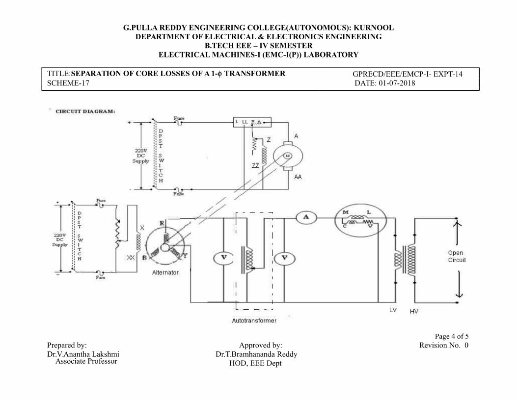
G.PULLA REDDY ENGINEERING COLLEGE(AUTONOMOUS): KURNOOLDEPARTMENT OF ELECTRICAL & ELECTRONICS ENGINEERING
B.TECH EEE – IV SEMESTERELECTRICAL MACHINES-I (EMC-I(P)) LABORATORY
TITLE:SEPARATION OF CORE LOSSES OF A 1- TRANSFORMER GPRECD/EEE/EMCP-I- EXPT-14SCHEME-17 DATE: 01-07-2018
Prepared by:Dr.V.Anantha Lakshmi
Associate Professor
Approved by:Dr.T.Bramhananda Reddy
HOD, EEE Dept
Page 4 of 5Revision No. 0