© g. lufft mess- und regeltechnik gmbh, fellbach,...
TRANSCRIPT


© G. Lufft Mess- und Regeltechnik GmbH, Fellbach, Germany. We reserve the right to make technical changes at any time without notice.
48.7230-WSX-E
Document version V27 (01/2015)

Operating Manual Smart Weather Sensor
G. Lufft Mess- und Regeltechnik GmbH, Fellbach, Germany 3
Contents
1 Please Read Before Use ............................................................................................................................................. 5 1.1 Symbols Used ..................................................................................................................................................... 5 1.2 Safety Instructions ............................................................................................................................................... 5 1.3 Designated Use ................................................................................................................................................... 5 1.4 Incorrect Use ....................................................................................................................................................... 5 1.5 Guarantee ............................................................................................................................................................ 5 1.6 Brand Names ....................................................................................................................................................... 5
2 Scope of Delivery ........................................................................................................................................................ 6
3 Order Numbers ............................................................................................................................................................ 7 3.1 Accessories ......................................................................................................................................................... 9 3.2 Spare Parts .......................................................................................................................................................... 9 3.3 Additional Documents and Software .................................................................................................................... 9
4 Equipment Description ............................................................................................................................................. 10 4.1 Air Temperature and Humidity ........................................................................................................................... 10 4.2 Air Pressure ....................................................................................................................................................... 10 4.3 Precipitation ....................................................................................................................................................... 11 4.4 Wet Bulb Temperature....................................................................................................................................... 11 4.5 Specific Enthalpy ............................................................................................................................................... 11 4.6 Air Density ......................................................................................................................................................... 11 4.7 Wind .................................................................................................................................................................. 11 4.8 Compass ........................................................................................................................................................... 11 4.9 Heating .............................................................................................................................................................. 11 4.10 Global Radiation ................................................................................................................................................ 11 4.11 Leaf Wetness ..................................................................................................................................................... 11 4.12 External Temperature Sensor ............................................................................................................................ 11 4.13 External Rain Gauge ......................................................................................................................................... 11 4.14 Sensor Technology (example: WS600-UMB) .................................................................................................... 12
5 Generation of Measurements ................................................................................................................................... 13 5.1 Current Measurement (act) ................................................................................................................................ 13 5.2 Minimum and Maximum Values (min and max) ................................................................................................. 13 5.3 Average Value (avg) .......................................................................................................................................... 13 5.4 Vectorial Average Value (vct) ............................................................................................................................ 13
6 Measurement Output ................................................................................................................................................ 14 6.1 Air and Dewpoint Temperature .......................................................................................................................... 14 6.2 Wind Chill Temperature ..................................................................................................................................... 14 6.3 Humidity ............................................................................................................................................................. 14 6.4 Air Pressure ....................................................................................................................................................... 14 6.5 Wet Bulb Temperature....................................................................................................................................... 15 6.6 Specific Enthalpy ............................................................................................................................................... 15 6.7 Air Density ......................................................................................................................................................... 15 6.8 Wind Speed ....................................................................................................................................................... 16 6.9 Wind Direction ................................................................................................................................................... 16 6.10 Wind Measurement Quality ............................................................................................................................... 17 6.11 Compass ........................................................................................................................................................... 17 6.12 Precipitation Quantity - Absolute ....................................................................................................................... 18 6.13 Precipitation Quantity - Differential .................................................................................................................... 18 6.14 Precipitation Intensity......................................................................................................................................... 18 6.15 Precipitation Type .............................................................................................................................................. 19 6.16 Heating Temperature ......................................................................................................................................... 19 6.17 Global Radiation ................................................................................................................................................ 19 6.18 Leaf Wetness ..................................................................................................................................................... 20 6.19 Service Messages ............................................................................................................................................. 20

Operating Manual Smart Weather Sensor
4 G. Lufft Mess- und Regeltechnik GmbH, Fellbach, Germany
7 Installation ................................................................................................................................................................ 21 7.1 Fastening .......................................................................................................................................................... 21 7.2 North Alignment ................................................................................................................................................ 22 7.3 Selecting the Installation Location..................................................................................................................... 23
8 Connections .............................................................................................................................................................. 25 8.1 Supply Voltage .................................................................................................................................................. 25 8.2 RS485 Interface ................................................................................................................................................ 26 8.3 Connection to ISOCON-UMB (8160.UISO) ...................................................................................................... 27 8.4 Use of Surge Protection (8379.USP) ................................................................................................................ 27 8.5 Connection of the Leaf Wetness Sensor ........................................................................................................... 27 8.6 Connection of External Temperature and Precipitation Sensors ...................................................................... 27
9 Commissioning ........................................................................................................................................................ 28
10 Configuration and Test ............................................................................................................................................ 29 10.1 Factory Settings ................................................................................................................................................ 29 10.2 Configuration with the UMB-Config-Tool ........................................................................................................... 29 10.3 Function Test with UMB-Config-Tool ................................................................................................................ 35 10.4 Operating Modes of the Smart Weather Sensor ............................................................................................... 36 10.5 Operating Modes for Equipment Heating .......................................................................................................... 38
11 Firmware Update ...................................................................................................................................................... 40
12 Maintenance .............................................................................................................................................................. 40 12.1 Maintenance of the Rain Gauge ....................................................................................................................... 41
13 Technical Data .......................................................................................................................................................... 42 13.1 Measuring Range / Accuracy ............................................................................................................................ 44 13.2 Drawings ........................................................................................................................................................... 47
14 EC Certificate of Conformity ................................................................................................................................... 58
15 Fault Description ...................................................................................................................................................... 59
16 Disposal .................................................................................................................................................................... 60 16.1 Within the EC .................................................................................................................................................... 60 16.2 Outside the EC ................................................................................................................................................. 60
17 Repair / Corrective Maintenance ............................................................................................................................. 60 17.1 Technical Support ............................................................................................................................................. 60
18 External Sensors ...................................................................................................................................................... 61 18.1 Leaf Wetness Sensor WLW100 ........................................................................................................................ 61 18.2 External Temperature and Precipitation Sensors ............................................................................................. 63
19 Appendix ................................................................................................................................................................... 65 19.1 Channel List Summary ...................................................................................................................................... 65 19.2 Channel List Summary per TLS2002 FG3 ........................................................................................................ 67 19.3 Communication in Binary Protocol .................................................................................................................... 68 19.4 Communication in ASCII Protocol ..................................................................................................................... 71 19.5 Communication in Terminal Mode .................................................................................................................... 74 19.6 Communication in SDI-12 Mode ....................................................................................................................... 77 19.7 Communication in Modbus Mode.................................................................................................................... 118 19.8 Communication: XDR Protocol ....................................................................................................................... 127
20 List of Figures ......................................................................................................................................................... 139
21 Index ........................................................................................................................................................................ 140

Operating Manual Smart Weather Sensor
G. Lufft Mess- und Regeltechnik GmbH, Fellbach, Germany 5
1 Please Read Before Use
This manual is valid for devices of the Lufft WS family with device version 31 or higher(7/2012).Some functions or features specified in this manual may not be available or may not be valid with older device versions. The device version is indicated as the last number of the serial number, e.g.: the device with SN: 063.1010.0701.021has the device version 21.
If you are using an older device of the WS family, please refer to the manual for device versions prior to 30 (www.lufft.com/en/support/downloads).
1.1 Symbols Used
Important information concerning potential hazards to the user
Important information concerning the correct operation of the equipment
1.2 Safety Instructions
Installation and commissioning must be carried out by suitably qualified specialist personnel only.
Never take measurements on or touch live electrical parts.
Pay attention to the technical data and storage and operating conditions.
1.3 Designated Use
The equipment must only be operated within the range of the specified technical data.
The equipment must only be used under the conditions and for the purposes for which it was designed.
The safety and operation of the equipment can no longer be guaranteed if it is modified or adapted.
1.4 Incorrect Use
If the equipment is installed incorrectly
It may not function.
It may be permanently damaged.
Danger of injury may exist if the equipment is allowed to fall.
If the equipment is not connected correctly
It may not function.
It may be permanently damaged.
The possibility of an electrical shock may exist.
1.5 Guarantee
The guarantee period is 12 months from the date of delivery. The guarantee is forfeited if the designated use is violated.
1.6 Brand Names
All brand names referred to are subject without limitation to the valid trademark and ownership rights of the respective owner.

Operating Manual Smart Weather Sensor
6 G. Lufft Mess- und Regeltechnik GmbH, Fellbach, Germany
2 Scope of Delivery
Equipment
WS200-UMB WS300-UMB WS400-UMB WS500-UMB WS600-UMB
WS301-UMB WS501-UMB WS401-UMB WS601-UMB WS700-UMB
WS310-UMB WS510-UMB
Connection cable 10m
Operating manual

Operating Manual Smart Weather Sensor
G. Lufft Mess- und Regeltechnik GmbH, Fellbach, Germany 7
3 Order Numbers
WS200-UMB 8371.U01
Wind Direction
Wind Speed
Compass
WS300-UMB 8372.U01
Air Temperature
Relative Humidity
Air Pressure
WS301-UMB 8374.U01
WS302-UMB 8374.U10
WS303-UMB 8374.U11
WS304-UMB 8374.U12
WS310-UMB 8374.U13
Air Temperature
Relative Humidity
Air Pressure
Global Radiation
WS400-UMB 8369.U01 (Europe, USA, Canada)
Precipitation Radar 8369.U02 (UK)
Air Temperature
Relative Humidity
Air Pressure
WS401-UMB 8377.U01
Precipitation Rain Gauge
Air Temperature
Relative Humidity
Air Pressure
WS500-UMB 8373.U01
Wind Direction
Wind Speed
Air Temperature
Relative Humidity
Air Pressure
Compass

Operating Manual Smart Weather Sensor
8 G. Lufft Mess- und Regeltechnik GmbH, Fellbach, Germany
WS501-UMB 8375.U01
WS502-UMB 8375.U10
WS503-UMB 8375.U11
WS504-UMB 8375.U12
WS510-UMB 8375.U13
Wind Direction
Wind Speed
Air Temperature
Relative Humidity
Air Pressure
Compass
Global Radiation
WS600-UMB 8370.U01 (Europe, USA, Canada)
Precipitation Radar 8370.U02 (UK)
Wind Direction
Wind Speed
Air Temperature
Relative Humidity
Air Pressure
Compass
WS601-UMB 8376.U01
Precipitation Rain Gauge
Wind Direction
Wind Speed
Air Temperature
Relative Humidity
Air Pressure
Compass
WS700-UMB 8380.U01 (Europe, USA, Canada)
Precipitation Radar
Wind Direction
Wind Speed
Air Temperature
Relative Humidity
Air Pressure
Compass
Global Radiation

Operating Manual Smart Weather Sensor
G. Lufft Mess- und Regeltechnik GmbH, Fellbach, Germany 9
3.1 Accessories
Power supply unit 24V/100VA 8366.USV1
ISOCON-UMB 8160.UISO
Surge protection 8379.USP
Leaf Wetness Sensor WLW100 (WS401-UMB, WS601-UMB only)
8358.10
External Rain Gauge WTB100 8353.10
External Temperature Sensors
Temperature Sensor WT1 8160.WT1
Passive Road Surface Temperature Sensor WST1 8160.WST1
3.2 Spare Parts
Connection cable 10m On enquiry
3.3 Additional Documents and Software
You can download the following documents and software via the Internet at www.lufft.com.
Operating Manual This document
UMB-Config-Tool Windows® software for testing, firmware updates and
configuration of UMB devices
UMB Protocol Communications protocol for UMB devices
Firmware The current device firmware

Operating Manual Smart Weather Sensor
10 G. Lufft Mess- und Regeltechnik GmbH, Fellbach, Germany
4 Equipment Description
The WS family is a range of low cost smart combination of weather sensors for the acquisition of a variety of measurement variables, as used for example for environmental data logging in road traffic management systems. Depending on the model, each device has a different combination of sensors for the various measurement variables.
WS
200-
UM
B
WS
300-
UM
B
WS
301-
UM
B**
WS
400-
UM
B
WS
401-
UM
B
WS
500-
UM
B
WS
501-
UM
B**
*
WS
600-
UM
B
WS
601-
UM
B
WS
700-
UM
B
Air temperature ● ● ● ● ● ● ● ● ●
Humidity ● ● ● ● ● ● ● ● ●
Air pressure ● ● ● ● ● ● ● ● ●
Precipitation ● ●* ● ●* ●
Wind direction ● ● ● ● ● ●
Wind speed ● ● ● ● ● ●
Compass ● ● ● ● ● ●
Global Radiation ● ● ●
Leaf Wetness (ext) ● ●
Temperature (ext) ● ● ● ● ● ● ● ● ● ●
Rain Gauge (ext) ● ● ● ● ●
Power Save 2 ● ● ● ● ● ● ● *) WS401-UMB and WS601-UMB use a rain gauge for precipitation measurement
**) is also valid for WS302-UMB, WS303-UMB, WS304-UMB, WS310-UMB
***) is also valid for WS502-UMB, WS503-UMB, WS504-UMB, WS510-UMB
Sensors marked (ext) in the table are additional accessories and not included with the device. The table shows which external sensors can be connected to the different models.
Note: The external temperature sensor and the external rain gauge use the same input, so only one of them can be connected simultaneously.
Attention: Please note that, due to the approval of the radar sensor used, there are different country options on equipment which includes precipitation measurement by radar technology.
The equipment is connected by way of an 8 pole screw connector and associated connection cable (length 10m).
The measured values are requested over the RS485 interface in accordance with UMB protocol.
During commissioning, configuration and measurement polling takes place using the UMB-Config-Tool (Windows
® PC software).
4.1 Air Temperature and Humidity
Temperature is measured by way of a highly accurate NTC-resistor while humidity is measured using a capacitive humidity sensor. In order to keep the effects of external influences (e.g. solar radiation) as low as possible, these sensors are located in a ventilated housing with radiation protection. In contrast to conventional non-ventilated sensors, this allows significantly more accurate measurement during high radiation conditions.
Additional variables such as dewpoint, absolute humidity and mixing ratio are calculated from air temperature and relative humidity, taking account of air pressure.
4.2 Air Pressure
Absolute air pressure is measured by way of a built-in sensor (MEMS). The relative air pressure referenced to sea level is calculated using the barometric formula with the aid of the local altitude, which is user-configurable on the equipment.

Operating Manual Smart Weather Sensor
G. Lufft Mess- und Regeltechnik GmbH, Fellbach, Germany 11
4.3 Precipitation
Tried and tested radar technology from the R2S-UMB sensor is used to measure precipitation. The precipitation sensor works with a 24GHz Doppler radar, which measures the drop speed and calculates precipitation quantity and type by correlating drop size and speed. WS401-UMB and WS601-UMB are using an unheated rain gauge for precipitation measurement. This version can be recommended for low power application etc.
4.4 Wet Bulb Temperature
The wet bulb temperature is the temperature of a moist or icy surface exposed to air flow.
4.5 Specific Enthalpy
Parameter of state of the humid air, composed of the specific enthalpies (heat capacity) of the components of the mixture and related to the mass fraction of the dry air (at 0°C).
4.6 Air Density
The air density indicates how much mass in a given volume of air is contained and it is calculated from the measured values of air temperature, humidity and air pressure.
4.7 Wind
The wind meter uses 4 ultrasonic sensors which take cyclical measurements in all directions. The resulting wind speed and direction are calculated from the measured run-time sound differential. The sensor delivers a quality output signal indicating how many good readings were taken during the measurement interval.
4.8 Compass
The integrated electronic compass can be used to check the north – south adjustment of the sensor housing for wind direction measurement. It is also used to calculate the compass corrected wind direction.
4.9 Heating
The precipitation sensor and wind meter are heated for operation in winter.
4.10 Global Radiation
The global radiation is measured by a pyranometer mounted in the top cover of the Smart Weather Sensor.
4.11 Leaf Wetness
WS401-UMB and WS601-UMB can be equipped with an external sensor for leaf wetness evaluation.
4.12 External Temperature Sensor
Optionally all models may be equipped with an external NTC temperature sensor for the acquisition from additional measurement points. The type of NTC is the same as used for the internal air temperature sensor.
External temperature sensor and external rain gauge can not be connected at the same time.
4.13 External Rain Gauge
Models without integrated precipitation acquisition can be equipped with an external rain gauge.
External rain gauge and external temperature sensor can not be connected at the same time.

Operating Manual Smart Weather Sensor
12 G. Lufft Mess- und Regeltechnik GmbH, Fellbach, Germany
Figure 1: Sensor Technology
4.14 Sensor Technology (example: WS600-UMB)
Precipitation sensor
(heated)
Wind meter
(heated)
Air temperature and relative humidity with fan on underside of device
Connector
Mounting bracket with springs and self-locking nuts
Air pressure sensor in device
Notch for attaching connection cable

Operating Manual Smart Weather Sensor
G. Lufft Mess- und Regeltechnik GmbH, Fellbach, Germany 13
5 Generation of Measurements
5.1 Current Measurement (act)
In accordance with the specified sampling rate, the value of the last measurement is transmitted when the current measurement value is requested. Each measurement is stored in a circular buffer for the subsequent calculation of minimum, maximum and average values.
5.2 Minimum and Maximum Values (min and max)
When requesting the minimum and maximum values, the corresponding value is calculated - via the circular buffer at the interval (1 – 10 minutes) specified in the configuration - and transmitted.
Note: In the case of wind direction, the minimum / maximum value indicates the direction at which the minimum / maximum wind speed was measured.
5.3 Average Value (avg)
When requesting the average value, this is calculated - via the circular buffer at the interval (1 – 10 minutes) specified in the configuration - and transmitted. In this way moving averages can also be calculated.
For some values the standard deviation is calculated for the same interval. The calculation of standard deviation will only be activated after the related UMB channel has been requested for the first time.
5.4 Vectorial Average Value (vct)
In the specific case of wind measurement, measurements are calculated vectorially. To this end, the average values of the vectors are generated internally. Hence the value (wind speed) and angle (wind direction) of the vector are calculated.
Note: On delivery, the interval for the calculation of minimum, maximum and average values is set at 10 minutes. If necessary, this can be adjusted to the particular requirements (1 – 10 minutes) with the aid of the UMB-Config-Tool (see page 29).
Note: The evaluation of the standard deviation values is deactivated after power on of the device. The function will be activated with the first request to any of the standard deviation channels.
To get standard deviation values of the first integration period after power on a dummy request to any one of the standard deviation channels should be inserted.
Operating Manual Smart Weather Sensor
14 G. Lufft Mess- und Regeltechnik GmbH, Fellbach, Germany
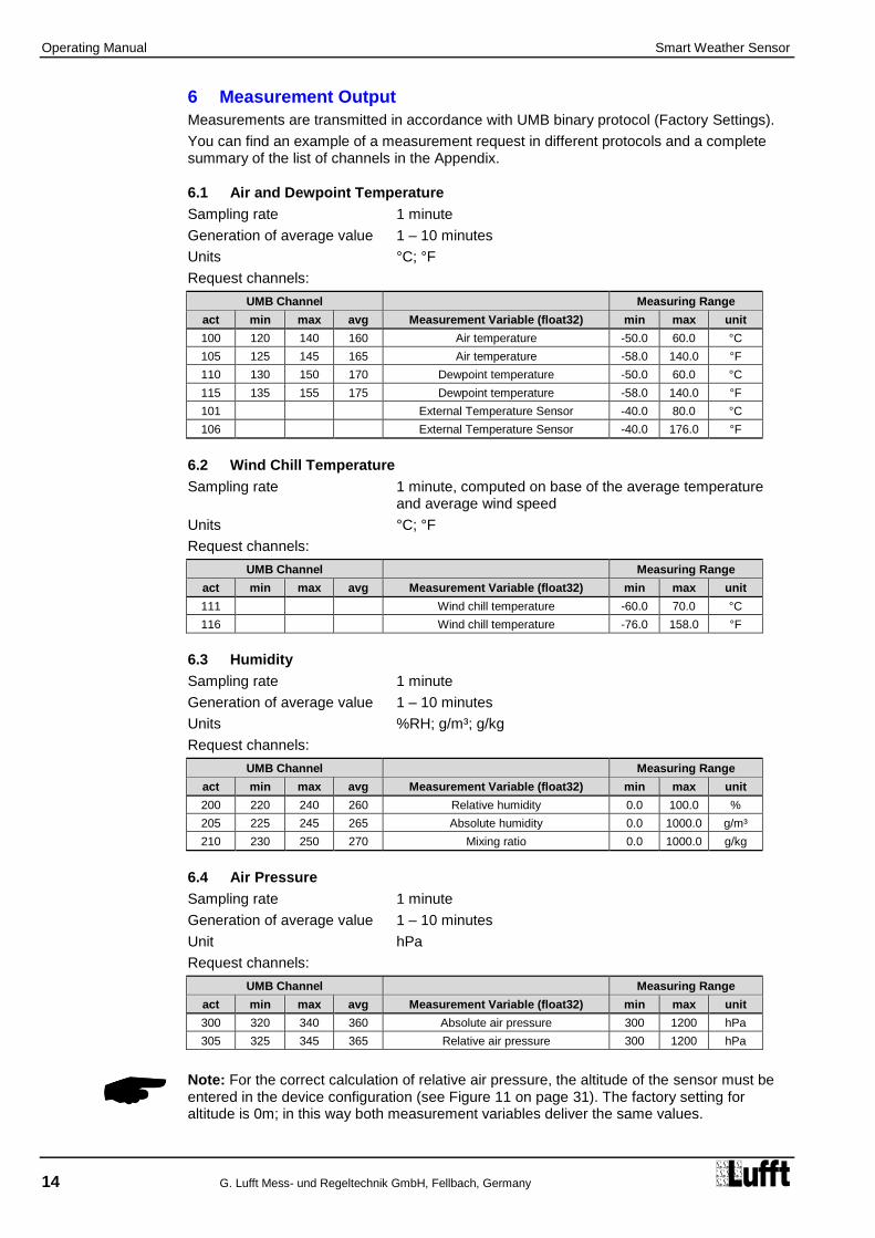
6 Measurement Output
Measurements are transmitted in accordance with UMB binary protocol (Factory Settings).
You can find an example of a measurement request in different protocols and a complete summary of the list of channels in the Appendix.
6.1 Air and Dewpoint Temperature
Sampling rate 1 minute
Generation of average value 1 – 10 minutes
Units °C; °F
Request channels:
UMB Channel Measuring Range
act min max avg Measurement Variable (float32) min max unit
100 120 140 160 Air temperature -50.0 60.0 °C
105 125 145 165 Air temperature -58.0 140.0 °F
110 130 150 170 Dewpoint temperature -50.0 60.0 °C
115 135 155 175 Dewpoint temperature -58.0 140.0 °F
101 External Temperature Sensor -40.0 80.0 °C
106 External Temperature Sensor -40.0 176.0 °F
6.2 Wind Chill Temperature
Sampling rate 1 minute, computed on base of the average temperature and average wind speed
Units °C; °F
Request channels:
UMB Channel Measuring Range
act min max avg Measurement Variable (float32) min max unit
111 Wind chill temperature -60.0 70.0 °C
116 Wind chill temperature -76.0 158.0 °F
6.3 Humidity
Sampling rate 1 minute
Generation of average value 1 – 10 minutes
Units %RH; g/m³; g/kg
Request channels:
UMB Channel Measuring Range
act min max avg Measurement Variable (float32) min max unit
200 220 240 260 Relative humidity 0.0 100.0 %
205 225 245 265 Absolute humidity 0.0 1000.0 g/m³
210 230 250 270 Mixing ratio 0.0 1000.0 g/kg
6.4 Air Pressure
Sampling rate 1 minute
Generation of average value 1 – 10 minutes
Unit hPa
Request channels:
UMB Channel Measuring Range
act min max avg Measurement Variable (float32) min max unit
300 320 340 360 Absolute air pressure 300 1200 hPa
305 325 345 365 Relative air pressure 300 1200 hPa
Note: For the correct calculation of relative air pressure, the altitude of the sensor must be entered in the device configuration (see Figure 11 on page 31). The factory setting for altitude is 0m; in this way both measurement variables deliver the same values.

Operating Manual Smart Weather Sensor
G. Lufft Mess- und Regeltechnik GmbH, Fellbach, Germany 15
6.5 Wet Bulb Temperature
Sampling rate 1 minute
Units °C; °F
Request channels:
UMB Channel Measuring Range
act Measurement Variable (float32) min max unit
114 Wet Bulb Temperature -50.0 60.0 °C
119 Wet Bulb Temperature -58.0 140.0 °F
6.6 Specific Enthalpy
Sampling rate 1 minute
Unit kJ/kg
Request channels:
UMB Channel Measuring Range
act Measurement Variable (float32) min max unit
215 Specific Enthalpy -100.0 1000.0 kJ/kg
6.7 Air Density
Sampling rate 1 minute
Unit kg/m³
Request channels:
UMB Channel Measuring Range
act Measurement Variable (float32) min max unit
310 Air Density 0.0 3.0 kg/m³

Operating Manual Smart Weather Sensor
16 G. Lufft Mess- und Regeltechnik GmbH, Fellbach, Germany
6.8 Wind Speed
Sampling rate 10 seconds
Generation of average value 1 – 10 minutes
Generation of maximum value 1 – 10 minutes based on the internal second measurements
Units m/s; km/h; mph; kts
Response threshold 0.3 m/s
Request channels:
UMB Channel Measuring Range
act min max avg vct Measurement Variable (float32) min max unit
400 420 440 460 480 Wind Speed 0 75.0 m/s
405 425 445 465 485 Wind Speed 0 270.0 km/h
410 430 450 470 490 Wind Speed 0 167.8 mph
415 435 455 475 495 Wind Speed 0 145.8 kts
401 Wind Speed Fast 0 75.0 m/s
406 Wind Speed Fast 0 270.0 km/h
411 Wind Speed Fast 0 167.8 mph
416 Wind Speed Fast 0 145.8 kts
403 Wind Speed Standard Deviation * 0 75.0 m/s
413 Wind Speed Standard Deviation * 0 167.8 mph
Note: The second measurements are averaged over 10 seconds for the output of the current (act) measurement. The 'fast' channels deliver every second a value.
6.9 Wind Direction
Sampling rate 10 seconds
Generation of average value 1 – 10 minutes
Generation of maximum value 1 – 10 minutes based on the internal second measurements
Unit °
Response threshold 0.3 m/s
Request channels:
UMB Channel Measuring Range
act min max avg vct Measurement Variable (float32) min max unit
500 520 540 580 Wind Direction 0 359.9 °
501 Wind Direction Fast 0 359.9 °
502 Wind Direction Corrected 0 359.9 °
503 Wind Dir. Standard Deviation * 0 359.0 °
Note: The second measurements are averaged over 10 seconds for the output of the current (act) measurement. The 'fast' channels deliver every second a value.
The minimum / maximum wind direction indicates the direction at which the minimum / maximum wind speed was measured.
The corrected wind direction is calculated from the wind direction measured by the wind sensor and the heading measured by the compass.
Optionally the compass correction of the wind direction can be activated for all wind direction values. (Settings by UMB Config Tool)
Note: The correction function is designed for correction of the wind direction of a statically mounted sensor. If the alignment of the sensor changes during the measurement (i.e. if the sensor is mounted on a rotating platform or similar) the correction function will not in all cases work properly, especially not for the vector average.
It is of course possible to use the correction function for mobile measurement units, where the alignment is changed between measurement periods.
*) Note: The evaluation of the standard deviation values will be activated after the first request of a standard deviation channel. Please see p. 11.

Operating Manual Smart Weather Sensor
G. Lufft Mess- und Regeltechnik GmbH, Fellbach, Germany 17
6.10 Wind Measurement Quality
Sampling rate 10 seconds
Unit %
Request channels:
UMB Channel Measuring Range
act min max avg vct Measurement Variable (float32) min max unit
805 Wind Value Quality 0 100 %
806 Wind Value Quality (fast) 0 100 %
Note: The value is updated every 10 seconds and transmits the minimum wind measurement quality for the last 10 seconds interval.
The “fast” value indicates the measurement quality of the one second measurement value.
This value allows the user to assess how well the measurement system is functioning in the respective ambient conditions. In normal circumstances the value is 90 - 100%. Values up to 50% do not represent a general problem. If the value falls towards zero the measuring system is reaching its limits.
If during critical ambient conditions the system is no longer able to conduct reliable measurements, error value 55h (85d) is transmitted (device unable to execute valid measurement due to ambient conditions).
6.11 Compass
(only device version 030 or higher)
Sampling rate: 5 min
Unit °
Request channels:
UMB Channel Measuring Range
act min max avg vct Measurement Variable (float) min max unit
510 Compass Heading 0 359 °
Note: Reliable operation of the compass is only possible, if the sensor has been mounted according to the instructions in this manual, i.e. on top of the pole. Should the sensor be mounted on a traverse, the distribution of iron masses will be different from the situation during factory calibration. This may lead to additional deviation of the bearing. This also applies to lightning rods mounted at the pole top!
Dependent on the location of the installation the local declination of the earth magnetic field has to be considered. The declination value is entered using the UMB-Config-Tool (see page 31). The declination for the installation location can be found in the Internet, e.g. at
http://www-app3.gfz-potsdam.de/Declinationcalc/declinationcalc.html
http://www.ngdc.noaa.gov/geomagmodels/Declination.jsp
Note: When the fan is not rotating the compass measurement value will be influenced by the magnetic field of the fan. Normally the compass measurement will be performed with the fan rotating to compensate this influence. If, starting from device version 037, the fan will not be switched on in case of low operating voltage (less than 12V) deviations of the compass measurement value must be accepted.
Note: When the device is operated in Power Saving Mode 1 or 2 the compass measurement is performed only once after power on. Later changes of the orientation of the device will not be recognized.

Operating Manual Smart Weather Sensor
18 G. Lufft Mess- und Regeltechnik GmbH, Fellbach, Germany
6.12 Precipitation Quantity - Absolute
Sampling rate Event-dependent on reaching the response threshold
Response threshold 0.01mm (Radar)
Response threshold 0.2 / 0.5 mm (Rain Gauge)
Units l/m²; mm; in; mil
Request channels:
UMB Channel Measurement Variable (float32) Unit
600 Precipitation Quantity - Absolute l/m²
620 Precipitation Quantity - Absolute mm
640 Precipitation Quantity - Absolute in
660 Precipitation Quantity - Absolute mil
Note: This measurement indicates the accumulated precipitation quantity since the last device reboot. The measurement is retained for the duration of a short power failure. To reset this value, use the corresponding function in the UMB-Config-Tool (see page 34) or disconnect the device from the power supply for at least one hour.
6.13 Precipitation Quantity - Differential
Sampling rate Event-dependent on reaching the response threshold
Response threshold 0.01mm (Radar)
Response threshold 0.2 / 0.5 mm (Rain Gauge)
Units l/m²; mm; in; mil
Request channels:
UMB Chanel Measurement Variable (float32) Unit
605 Precipitation Quantity - Differential l/m²
625 Precipitation Quantity - Differential mm
645 Precipitation Quantity - Differential in
665 Precipitation Quantity - Differential mil
Note: Each request from a differential channel sets the accumulated quantity back to zero. If the response from the device is lost due to a transmission error (e.g. poor GPRS connection), the quantity accumulated to date is also lost. The quantity accumulated to date is also reset each time the equipment is rebooted.
6.14 Precipitation Intensity
Sampling rate 1 minute
Response threshold 0.6 mm/h
Units l/m²/h; mm/h; in/h; mil/h
Request channels:
UMB Channel Measurement Variable (float32) Range Unit
800 Precipitation Intensity 0 … 200.0 l/m²/h
820 Precipitation Intensity 0 … 200.0 mm/h
840 Precipitation Intensity 0 … 7.874 in/h
860 Precipitation Intensity 0 … 7874 mil/h
Note: The device versions with radar technology (WS400-UMB, WS600-UMB) calculate the precipitation intensity is always on the basis of the precipitation of the previous minute.
The lower resolution of the rain gauge would lead to high fluctuation of the intensity values, so the rain gauge versions (WS401-UMB and WS601-UMB), as well as the external rain gauge, use the accumulated precipitation of the last 60 minutes prior to the current measurement for intensity calculation.

Operating Manual Smart Weather Sensor
G. Lufft Mess- und Regeltechnik GmbH, Fellbach, Germany 19
6.15 Precipitation Type
Sampling rate Event-dependent on reaching the response threshold
Response threshold 0.002mm (Radar)
Response threshold 0.2 / 0.5 mm (Rain Gauge)
Follow-up time 2 minutes
Request channels:
UMB Channel Measurement Variable (uint8) Coding
700 Precipitation Type
0 = No precipitation
60 = Liquid precipitation, e.g. rain
70 = Solid precipitation, e.g. snow
40 = unspecified precipitation (WS401-UMB, WS601-UMB, external
rain gauge)
Note: A detected precipitation type remains valid for 2 minutes after the end of the precipitation event. In order to record precipitation types which only occur for a short period (e.g. short-term rain), the request interval should be 1 minute or shorter.
Ice, hail and sleet are transmitted as rain (60).
The versions WS401-UMB and WS601-UMB as well as the external rain gauge do not include detection of precipitation type, so in this case only type 40 (unspecified precipitation) is indicated. Due to the function of the rain gauge only liquid or molten precipitation can be recognized.
6.16 Heating Temperature
Sampling Rate 1 Minute
Units °C; °F
Request Channels:
UMB Channel Measuring Range
act min max avg Measurement Variable (float32) min max Unit
112 Heating Temperature Wind Sensor -50.0 150.0 °C
113 Heating Temperature Precipitation Sensor -50.0 150.0 °C
117 Heating Temperature Wind Sensor -58.0 302.0 °F
118 Heating Temperature Precipitation Sensor -58.0 302.0 °F
6.17 Global Radiation
Sampling Rate 10 seconds
Generation of average values 1 – 10 minutes *)
Unit W/m²
Request Channels:
UMB Channel Measuring Range
act min max avg Measurement Variable (float32) min max unit
900 920 940 960 Global Radiation 0.0 1400.0 W/m²
*) Note: The average, maximum and minimum values are evaluated from the 1 minute averages of the 10 second spot value.
When operated in Power Saving Mode 1 (see page 36) the WS700-UMB will measure the global radiation only once per minute.
Operating Manual Smart Weather Sensor
20 G. Lufft Mess- und Regeltechnik GmbH, Fellbach, Germany
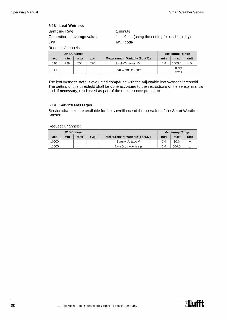
6.18 Leaf Wetness
Sampling Rate 1 minute
Generation of average values 1 – 10min (using the setting for rel. humidity)
Unit mV / code
Request Channels:
UMB Channel Measuring Range
act min max avg Measurement Variable (float32) min max unit
710 730 750 770 Leaf Wetness mV 0.0 1500.0 mV
711 Leaf Wetness State 0 = dry
1 = wet
The leaf wetness state is evaluated comparing with the adjustable leaf wetness threshold. The setting of this threshold shall be done according to the instructions of the sensor manual and, if necessary, readjusted as part of the maintenance procedure.
6.19 Service Messages
Service channels are available for the surveillance of the operation of the Smart Weather Sensor.
Request Channels:
UMB Channel Measuring Range
act min max avg Measurement Variable (float32) min max unit
10000 Supply Voltage V 0.0 50.0 V
11000 Rain Drop Volume µ 0.0 500.0 µl

Operating Manual Smart Weather Sensor
G. Lufft Mess- und Regeltechnik GmbH, Fellbach, Germany 21
Figure 2: Fastening to the Mast
7 Installation
The sensor bracket is designed to be installed on the top of a mast with a diameter of 60 – 76mm.
The following tools are required for the installation:
Open-end or ring spanner (SW13)
Compass for aligning the wind meter to the North
7.1 Fastening
Loosen nuts
Push the sensor onto the top of the mast from above
Tighten the nuts evenly until contact is made with the springs but the sensor can still be moved easily
Align the sensor to the North (for wind meters)
Tighten both nuts with 3 revolutions
Mast tube
Mounting bracket
Springs
Nuts with washers

Operating Manual Smart Weather Sensor
22 G. Lufft Mess- und Regeltechnik GmbH, Fellbach, Germany
Figure 3: North Markings
Figure 4: Alignment to North
7.2 North Alignment
In order for the wind direction to display correctly, the sensor must be aligned to the North. The sensor has a number of directional arrows for this purpose.
Procedure:
If the sensor is already installed, first loosen both nuts evenly until you can turn the sensor easily
Using the compass, identify the North and fix a point of reference on the horizon
Position the sensor in such a way that the South and North wind sensors are in alignment with the fixed point of reference in the North
Tighten both nuts with 3 revolutions
poor good
Note: As the magnetic North Pole indicated by the compass differs from the Geographic North Pole, account must be taken of the declination (variation) at the location when aligning the sensor.
Depending on the location, the variation can be more than 15° (in North America for example). In Central Europe the variation can be largely ignored at present (< 3°). You can find further helpful information on this subject on the Internet.
Point of reference in the North

Operating Manual Smart Weather Sensor
G. Lufft Mess- und Regeltechnik GmbH, Fellbach, Germany 23
7.3 Selecting the Installation Location
In order to guarantee long service life and correct equipment operation, please pay attention to the following points when selecting the installation location.
7.3.1 General Instructions
Stable subsurface for installing the mast
Free access to the equipment for maintenance works
Reliable power supply for permanent operation
Good network coverage when transmitting over a mobile communications network
Note: The computed measurements specifically apply to the equipment location only. No conclusions can be drawn with regard to the wider environment or a complete road section.
ATTENTION:
Only approved and tested appliances (conductors, risers etc.) should be used to install the device on the mast.
All relevant regulations for working at this height must be observed.
The mast must be sized and anchored appropriately.
The mast must be earthed in accordance with regulations.
The corresponding safety regulations for working at road side and in the vicinity of the road carriageway must be observed.
If the equipment is installed incorrectly
It may not function.
It may be permanently damaged.
Danger of injury may exist if the equipment is allowed to fall.
7.3.2 Sensors with Wind Measurement / Compass
Installation at the top of the mast
Installation height at least 2m above the ground
Free field around the sensor
Note: Buildings, bridges, embankments and trees may corrupt the wind measurement. Equally, passing traffic may cause gusts which may influence the wind measurement.
Note: for accurate compass readings, an aluminium mast is recommended.
7.3.3 Sensors with Radar Precipitation Measurement
Installation on the top of the mast
Installation height at least 4.5m above the ground
Distance to road carriageway at least 10m
Distance from moving objects (e.g. trees, bushes and even bridges) at least 10m at the height of the sensor
Note: Falling or moving objects, e.g. falling leaves or leaves blowing in the wind, may cause false measurements and/or precipitation types.
Note: Strong wind can influence the accuracy of the precipitation measurement.
Note: When selecting the installation location please take care to position the device at a suitable distance from other systems incorporating a 24GHz radar sensor, such as traffic counting devices on overhead gantry signs. Otherwise cross effects and system malfunctions may occur. In the final analysis, the distance to other measuring systems also depends on their range of coverage and signal strength.

Operating Manual Smart Weather Sensor
24 G. Lufft Mess- und Regeltechnik GmbH, Fellbach, Germany
Figure 5: Installation Sketch
7.3.4 Sensors with Rain Gauge
Installation on the top of the mast or on crossbar with distance to the mast
Mast or crossbar mounting shall be exactly perpendicular, otherwise the precision of the rain gauge may be influenced.
Note: The location should be selected so that pollution of the rain gauge funnel by falling leaves etc. can be avoided as far as possible.
7.3.5 Sensors with Global Radiation Measurement
Installation on top of the pole
Shadow free location, if possible 360° free view to the horizon at the height of the pyranometer
Distance to shadow casting objects (trees, buildings) at least 10 times of the object height relative to the sensor.
7.3.6 Installation Sketch
Example WS600-UMB:
Road carriageway
min. 5 m
min. 4.5 m
WS600-UMB
Mast
min. 5 m
Tree, bush etc.

Operating Manual Smart Weather Sensor
G. Lufft Mess- und Regeltechnik GmbH, Fellbach, Germany 25
Figure 6: Connections
8 Connections
There is an 8 pole screw connector on the underside of the equipment. This serves to connect the supply voltage and interfaces by way of the supplied connection cable.
Equipment connector:
View on sensor connection
Pin assignment:
1 White Supply voltage ground 2 Brown Positive supply voltage 3 Green RS485_A (+) or SDI-12 GND 4 Yellow RS485_B (-) or SDI-12 Data Line 5 Grey External Sensor a 6 Pink External Sensor b 7 Blue Heating voltage ground 8 Red Positive heating voltage
The cable marking is in accordance with DIN 47100.
Note: The yellow protective cap must be removed before plugging in the equipment.
If the equipment is not connected correctly
- It may not function
- It may be permanently damaged
- The possibility of an electrical shock may exist
The supply voltage and the heating voltage are protected against polarity reversal.
Note: When operating the Smart Weather Sensor in SDI12 mode, line 3 (green) shall be connected only if the SDI12 logger is DC-isolated from the supply voltage of the device. If signal ground (SDI-12-GND) of the data logger and power supply ground are identical, only the SDI12-Data-Line (line 4, yellow) may be connected.
8.1 Supply Voltage
The supply voltage for the Smart Weather Sensor is 12 - 24V DC. The power supply unit used must be approved for operation with equipment of protection class III (SELV).
Starting with device version 037 the Smart Weather Sensor has an extended supply voltage range of 4 … 32V DC. Operation with a supply voltage of 24V is recommended. Limitations apply in case of supply voltages lower than 12V (see below).
8.1.1 Limitations in 12V mode
If the heating is operated on 12V DC, account must be taken of the functional restrictions in winter operation.
Note: A heating voltage of 24V DC is recommended to guarantee full heating duty.

Operating Manual Smart Weather Sensor
26 G. Lufft Mess- und Regeltechnik GmbH, Fellbach, Germany
8.1.2 Limitations in Case of Operation with Supply Voltage Below 12V
When operating a Smart Weather Sensor (device version >= 037) with supply voltages lower than 12V DC, the fan will be not switched on, independent of the fan operating mode. This may influence the accuracy of temperature and humidity measurement in case of solar radiation.
Additionally deviations of the compass measurement values have to be accepted.
When operating the Smart Weather Sensor in Power Save Modes with supply voltages below 12V the minimal supply voltage depends on the length of the connection cable.
The minimal permitted supply voltage (UBmin)can be approximately evaluated from the equation:
UBmin = 4V + 0.3V (cable length / m)
The minimal supply voltage for a 10m cable is then UBmin = 6V. The influence of the cable length on minimal supply voltage can be reduced by using of a cable with larger wire cross section.
8.2 RS485 Interface
The equipment has an electrically isolated, half-duplex, 2 wire RS485 interface for configuration, measurement polling and the firmware update.
See page 42 for technical details.

Operating Manual Smart Weather Sensor
G. Lufft Mess- und Regeltechnik GmbH, Fellbach, Germany 27
Figure 7: Connection to ISOCON-UMB
8.3 Connection to ISOCON-UMB (8160.UISO)
Warning: The heating voltage (red = positive heating voltage; blue = heating voltage ground) is not connected to the ISOCON-UMB but wired direct to the power supply unit.
During installation please also refer to the operating manual for the ISOCON-UMB.
8.4 Use of Surge Protection (8379.USP)
When using surge protection (Order No.: 8379.USP), please pay attention to the connection example in the surge protection operating instructions.
8.5 Connection of the Leaf Wetness Sensor
The sensor versions WS401-UMB and WS601-UMB (precipitation measurement by rain gauge) can be equipped with an optional external leaf wetness sensor.
The connection terminals for the leaf wetness sensor are located inside the rain gauge module. The sensor connection cable is put through the cable bushing in the wall of the rain gauge module and connected to the terminals (see Chap. 18.1).
Terminal assignment for Leaf Wetness Sensor WLW100:
1 blank (shield) Ground
2 red Signal Voltage
3 white Sensor Supply Voltage 5V
8.6 Connection of External Temperature and Precipitation Sensors
External sensors are to be connected to pins 5 and 6 of the plug connector, i.e. to the gray and pink wires of the cable delivered with the Smart Weather Sensor.
The temperature sensors as well as the external rain gauge are unipolar, so any connection sequence can be chosen.
The type of external sensor has to be set using the UMB Config Tool.
For details please refer to Chapter18.
Brown: Positive voltage supply +24V
Green: RS485 Interface A
White: Supply voltage ground GND2
Yellow: RS485 Interface B

Operating Manual Smart Weather Sensor
28 G. Lufft Mess- und Regeltechnik GmbH, Fellbach, Germany
9 Commissioning
After the equipment has been installed and connected correctly, the sensor begins autonomously to take measurements. A Windows
® PC with serial interface, UMB-Config-
Tool software and interface cable (SUB-D 9 pole; jack - socket; 1:1) are required for configuration and test purposes.
Attention must be paid to the following points:
Check for correct equipment operation on site by carrying out a measurement request with the aid of the UMB-Config-Tool (see page 35).
Configure the local altitude in order to ensure the correct calculation of relative air pressure (see page 31).
The device must be aligned to the North in order to ensure correct wind measurement (see page 22), or the automatic compass correction must be activated (see page 31).
In order to get correct compass headings the local declination must be configured (see page 17and 31).
If several Smart Weather Sensors are operated on a UMB network, a unique device ID must be assigned to each device (see page 30).
There is no protective cover to remove on the sensor itself.

Operating Manual Smart Weather Sensor
G. Lufft Mess- und Regeltechnik GmbH, Fellbach, Germany 29
Figure 8: Sensor Selection
10 Configuration and Test
Lufft provides Windows® PC software (UMB-Config-Tool) for configuration purposes. The
sensor can also be tested and the firmware updated with the aid of this software.
10.1 Factory Settings
The Smart Weather Sensor is delivered with the following settings:
Class ID: 7 (cannot be modified)
Device ID: 1 (gives address 7001h = 28673d)
Baud rate: 19200
RS485 protocol: Binary
Calculation interval: 10 measurements
Local altitude: 0 m
Note: The device ID must be changed if several Smart Weather Sensors are operated on a UMB network, as each device requires a unique ID. It makes sense to start from ID 1 and continue in ascending order.
10.2 Configuration with the UMB-Config-Tool
The operation of the UMB-Config-Tool is described in detail in the operating instructions for the Windows
® PC software. For this reason only the menus and functions specific to the
Smart Weather Sensor are described here.
10.2.1 Sensor Selection
The Smart Weather Sensor is shown here with sensor selection WSx-UMB (Class ID 7).
Note: You do require the current version of the UMB-Config-Tool to configure the Smart Weather Sensor.
Note: All other devices which are used in the polling process, e.g. modems, LCOM etc., must be disconnected from the UMB network during configuration.

Operating Manual Smart Weather Sensor
30 G. Lufft Mess- und Regeltechnik GmbH, Fellbach, Germany
Figure 9: General Settings
Figure 10: Temperature, Humidity and Fan Settings
10.2.2 Configuration
After a configuration has been loaded, all relevant settings and values can be adjusted. Depending on the device type, only the settings pertinent to the respective available sensors are relevant.
10.2.3 General Settings
ID: Device ID (factory setting 1; assign device IDs to additional devices in ascending order).
Description: In order to differentiate the devices you can enter a description here, e.g. the location.
Linespeed: Transmission speed of the RS485 interface (factory setting 19200; DO NOT CHANGE for operation with ISOCON-UMB).
Protocol: Communications protocol of the sensor (UMB-Binary, UMB-ASCII, SDI-12, Modbus-RTU, Modbus-ASCII, Terminal-Mode).
Timeout: In the event of a temporary changeover of the communications protocol, the system switches back to the configured protocol after this time (in minutes)
Important note: If the baud rate is changed, after saving the configuration on the sensor, the sensor communicates at the new baud rate. When operating the sensor in a UMB network with ISOCON-UMB, this baud rate must not be changed; otherwise the sensor is no longer addressable and can no longer be configured.
10.2.4 Temperature, Humidity and Fan Settings
Offset: Absolute offset on the measurement in the unit of the accompanying channel (for on-site calibration).
Interval: Time in minutes for the minimum, maximum and average value calculation interval.
Fan: to reduce electrical power consumption, the fan can be switched off. Note: if the fan is switched off, all heaters will also be switched off! With the fan switched off deviations in temperature and humidity measurement can occur by solar radiation!
Note: In order to calculate dew point, absolute humidity and mixing ratio, the temperature and humidity measurement always requires the same interval. For this reason different intervals cannot be set.

Operating Manual Smart Weather Sensor
G. Lufft Mess- und Regeltechnik GmbH, Fellbach, Germany 31
Figure 11: Pressure Settings
Figure 12: Wind Settings
10.2.5 Pressure,
Offset: Absolute offset on the measurement in the unit of the accompanying channel.
Interval: Time in minutes for the minimum, maximum and average value calculation interval.
Altitude: Enter the local altitude in meters here for the correct calculation of relative air pressure (referenced to sea level).
10.2.6 Wind and Compass Settings
Offset: Absolute offset on the measurement in the unit of the accompanying channel.
Interval: Time in minutes for the minimum, maximum and average value calculation interval.
Windspeed min: Approach velocity onto the wind meter with effect from which a measurement is transmitted, in the unit of the accompanying channel.
Heater mode: The device can be configured for heating in different operating modes. Configure as ‘automatic’ in normal operating mode. You can find a precise description of the operating modes on page 38.
Local declination: Dependent on the location of the installation; the local declination of the earth magnetic field has to be considered.
Enable Compass for wind-direction correction: With activated compass correction all wind direction values will be corrected according to the alignment of the sensor, as evaluated by the compass.
Note: The offset is not used for the wind meter at present because on-site calibration is not possible in this case.

Operating Manual Smart Weather Sensor
32 G. Lufft Mess- und Regeltechnik GmbH, Fellbach, Germany
Figure 13: Precipitation Sensor Settings (Radar)
Figure 14: Precipitation Sensor Settings (Rain Gauge)
10.2.7 Precipitation Sensor Settings (Radar)
Heater mode: The device can be configured for heating in different operating modes. Configure as ‘automatic’ in normal operating mode. You can find a precise description of the operating modes on page 38.
Followup time precipitation type: for this time (in seconds) the detected precipitation type is shown; to cover all events, this time must be adjusted to the poll rate.
Note: All other parameters, especially those in the ‘Rainfall calibration data’ tab‚ may only be changed after consultation with the manufacturer, as they have a major influence on the functioning and accuracy of the sensor.
10.2.8 Precipitation Sensor Settings (Rain Gauge)
The rain gauge module can be operated with resolutions 0.2mm or 0.5mm. The setting of the resolution is to be done in two steps:
Mechanical setting
Configuration setting
The mechanical setting works by modifying the effective area of the funnel. The sensor is delivered with a reduction ring, which can be mounted on the funnel to reduce the area.
Funnel with reduction ring resolution 0.5mm
Funnel without reduction ring resolution 0.2mm
Then the resolution is set in the sensor configuration using the UMB Config Tool.
Caution: If mechanical setting and configuration setting do not conform, the sensor will deliver wrong precipitation values!

Operating Manual Smart Weather Sensor
G. Lufft Mess- und Regeltechnik GmbH, Fellbach, Germany 33
Figure 15: Energy Management Settings
10.2.9 Energy Management
By setting the operating and heating mode, the energy consumption of the device can be adapted to the circumstances of the installation.
The different settings are described in the following chapters:
operating modes of Smart Weather Sensor from page 36
operating modes of the heating from page 38

Operating Manual Smart Weather Sensor
34 G. Lufft Mess- und Regeltechnik GmbH, Fellbach, Germany
Figure 16: Reset Precipitation Quantity
10.2.10 Reset Precipitation Quantity
To reset the accumulated absolute precipitation quantity the UMB-Config-Tool offers the following function:
Options WSx-UMB reset rain
Confirm the reset with ‘Yes’
Note: The precipitation quantities are reset in ALL Smart Weather Sensors on the respective UMB network. The devices reboots after this function has been used.

Operating Manual Smart Weather Sensor
G. Lufft Mess- und Regeltechnik GmbH, Fellbach, Germany 35
Figure 17 Measurement Polling Channels
Figure 18 Example of Measurement Polling
10.3 Function Test with UMB-Config-Tool
The functions of the Smart Weather Sensor can be tested with the UMB-Config-Tool by polling various channels.
Note: All other devices which are used in the polling process, e.g. modems, LCOM etc., must be disconnected from the UMB network during configuration.
10.3.1 Channels for Measurement Polling
You can select the channel for measurement polling by the UMB-Config-Tool by clicking on the respective channel.
10.3.2 Example of Measurement Polling
Note: The UMB Config Tool is provided for test and configuration purposes only. It is not suitable for the permanent acquisition of measurement data. We recommend the use of professional software solutions for this purpose, e.g. Lufft SmartView3.

Operating Manual Smart Weather Sensor
36 G. Lufft Mess- und Regeltechnik GmbH, Fellbach, Germany
10.4 Operating Modes of the Smart Weather Sensor
The power consumption of the Smart Weather Sensor can be adjusted to the properties of the individual installation by setting the operation mode.
The operation of the power save modes however has certain constraints. These have to be considered when designing the installation.
In normal operation, where all specified properties of the Smart Weather Sensor are fully available, the power consumption is mostly determined by heating and fan operation.
10.4.1 Power Saving Mode 1
Following measures are active in power saving mode 1:
The ventilation of the temperature / humidity unit is switched off
All heaters are switched off
The radar rain sensor (WS700-UMB, WS600-UMB, WS400-UMB) is not working continuously. The sensor is activated once per minute for one second, if precipitation is detected, it remains turned on until the end of the event, otherwise it is deactivated after this one second again.
Compass measurement is only performed once after power up. The fan, which is otherwise deactivated, will be switched on shortly for the time of this measurement.
The WS700-UMB increases the measuring cycle time for global radiation from 10 seconds to 1 minute.
Note: This setting has the following restrictions:
With the fan switched off deviations in temperature and humidity measurement can occur by solar radiation.
Only limited winter operation is possible in this operating mode because any icing might prevent the correct operation of the rain sensor or wind meter.
The rain detection may be delayed up to 2 minutes. Short events are possibly not detected. Thus, deviations in the accuracy of the precipitation quantity are possible.
Compared with normal operation the power consumption of a WS600-UMB can be reduced to 10% even neglecting the heating. (during precipitation events the consumption is slightly higher, due to the rain sensor then permanently switched on, about 20% compared to normal operation).

Operating Manual Smart Weather Sensor
G. Lufft Mess- und Regeltechnik GmbH, Fellbach, Germany 37
10.4.2 Power Saving Mode 2
Power saving mode 2 permits another relevant reduction of the power consumption, but adds on the other hand more severe restrictions.
In this operation mode the device will be almost completely switched off and will wake up only by the data request for one measurement cycle. During measurement and data transmission the device will be switched on for about 10 – 15 sec. The total consumption will be mostly determined by the data request interval.
Note: This operating mode has the following restrictions:
All restrictions of power saving mode 1
Power saving mode 2 is not available for devices with radar rain sensor (WS700-UMB, WS600-UMB, WS400-UMB). We recommend devices with tipping bucket rain gauge for low power applications.
The calculation of average, minimum and maximum as well as precipitation intensity are not available. Only instantaneous values will be transmitted.
Compass measurement is only performed once after power up. The fan, which is otherwise deactivated, will be switched on shortly for the time of this measurement.
Communication protocol Modbus is not available
When using the UMB protocol a certain request sequence and timing is required (s. Chap. 19.3.7). The interval length must be at least 15sec to make sure that the measurement and transmission cycle can be completed. Shorter interval could cause the device to stay in transmission state without starting a new measurement.
The joint operation with other sensors in an UMB network is possible, but it has to be considered that each telegram (even when addressed to another device) will cause the Smart Weather Sensor to wake up for at least several seconds, thus increasing the total power consumption. The minimum interval length must be hold up under consideration of the telegrams with other addresses. Mixed operation of devices in power saving mode 2 with devices in normal operation and fast request rates within the same UMB network is not possible.

Operating Manual Smart Weather Sensor
38 G. Lufft Mess- und Regeltechnik GmbH, Fellbach, Germany
Figure 19: Operating Modes for Equipment Heating
10.5 Operating Modes for Equipment Heating
Heating is configured to ‘Automatic’ when the product is delivered. This is the recommended operating mode for heating the sensor.
You can set the following operating modes:
Heater Mode
WS200-UMB
WS400-UMB
WS500-UMB
WS501-UMB *)
WS600-UMB **)
WS601-UMB
Automatic ● ● ● ● ● ●
Off ● ● ● ● ● ●
Mode 1 ● ● ● ● ●
Eco-Mode 1 ● ● *) is also valid for WS502-UMB, WS503-UMB, WS504-UMB, WS510-UMB
**) is also valid for WS700-UMB
Note: Model WS30x-UMB and WS401-UMB are not heated.
The rain sensor and wind meter settings must be adjusted in the respective configuration mask. The examples show the wind meter setting.
10.5.1 Automatic
In this operating mode, the sensor is maintained constantly at the control temperature, generally in order to prevent the effects of snow and ice.
Setpoint Temp.: The heating controls at this temperature (in °C)
The settings for the other values are not relevant.
10.5.2 Off
In the ‘Off’ operating mode heating is completely disabled. Winter operation is not possible in this operating mode because any icing might prevent the correct operation of the rain sensor or wind meter.
The value settings are not relevant.
10.5.3 Mode 1
In ‘Mode 1’ operating mode heating is only enabled when the outside temperature falls below the HeatingMode1 temperature (in °C). In this mode power consumption can be reduced in frost-free situations with no great restriction on winter operation.
Setpoint Temp.: The heating controls at this temperature (in °C)
Heating mode1 Temp.: Threshold temperature (in °C) with effect from which air temperature heating is enabled
The ‘Eco Mode1 follow-up time’ setting is not relevant.

Operating Manual Smart Weather Sensor
G. Lufft Mess- und Regeltechnik GmbH, Fellbach, Germany 39
10.5.4 Eco-Mode 1
Eco Mode1 is an advanced energy saving mode.
Heating is only switched on when the following conditions are met:
The outside temperature is below the threshold temperature and precipitation was detected. Heating then runs at the control temperature for 30 minutes (after the last precipitation event).
When the outside temperature lies constantly below the threshold temperature and there was no heating for more than 20h, heating is switched on for 30 minutes as a precautionary measure in order to thaw any icing.
However, the precautionary 20h-heating only runs if the outside temperature was measured at below the threshold temperature for the entire period and conditions were constantly bright for at least 3 hours.
Setpoint Temp.: The heating controls at this temperature (in °C)
Heating mode1 Temp.: Threshold temperature (in °C) with effect from which heating is enabled
Eco mode1 follow-up time: Follow-up time (in minutes)
Examples:
Outside temperature constantly below 5°C; no precipitation for more than 24h
Outside temperature constantly below 5°C; with precipitation

Operating Manual Smart Weather Sensor
40 G. Lufft Mess- und Regeltechnik GmbH, Fellbach, Germany
11 Firmware Update
To keep the sensor in accordance with the latest state-of-the-art, it is possible to carry out a firmware update on site with no need to remove the sensor and return it to the manufacturer.
The firmware update is carried out with the aid of the UMB-Config-Tool.
The description of the firmware update can be found in the instructions for the UMB-Config-Tool. Please download the latest firmware and UMB-Config-Tool from our website www.lufft.com and install it on a Windows
® PC. You can find the instructions here:
Note: When a firmware update takes place, under certain circumstances the absolute precipitation quantities are reset (channel 600 – 660).
There is one firmware for the entire product family which supports all models (WSx_Release_Vxx.mot).
Important Note: please read the included text file in WSx_Release_Vxx.zip; it contains important information about the update!
12 Maintenance
In principle the equipment is maintenance-free.
However, it is recommended to carry out a functional test on an annual basis. When doing so, pay attention to the following points:
Visual inspection of the equipment for soiling
Check the sensors by carrying out a measurement request
Check the operation of the fan (not on WS200-UMB)
In addition, an annual calibration check by the manufacturer is recommended for the humidity sensor (not on WS200-UMB). It is not possible to remove or replace the humidity sensor. The complete Smart Weather Sensor must be sent to the manufacturer for testing.
Cleaning of the glass dome at regular intervals is suggested for devices with global radiation measurement. The length of the interval should be adapted to the local degree of pollution.
Devices with precipitation measurement by rain gauge (WS401-UMB, WS601-UMB): The rain gauge funnel needs to be cleaned at regular intervals (see below). The length of the interval should be adapted to the local degree of pollution.
Devices with leaf wetness sensor: Cleaning of the leaf wetness sensor at regular intervals is suggested. The length of the interval should be adapted to the local degree of pollution. A check and, if necessary, adjustment of the “Wet” threshold is recommended to include into the maintenance procedure.

Operating Manual Smart Weather Sensor
G. Lufft Mess- und Regeltechnik GmbH, Fellbach, Germany 41
Figure 20: WS601-UMB with removed funnel
12.1 Maintenance of the Rain Gauge
The function of the rain gauge will be significantly influenced by pollution of the funnel or the tipping bucket mechanism. Regular check and, if necessary, cleaning is required. The maintenance interval depends very much on local conditions and also on seasons (leaves, pollen, etc.) and therefore cannot be exactly defined here (it may be in the range of weeks).
Only clean when obviously polluted
Avoid moving the tipping mechanism (otherwise wrong counts will occur)
Use water, soft cloth and / or a soft brush for cleaning
Unlock funnel by turning it to the left and lift it off
Clean funnel, specially the sieve slots
Check the inside of the rain gauge module for pollution, especially for spider webs and insects, if necessary, clean it
Check tipping bucket for pollution, if necessary wash carefully with clean water. Caution: each movement of the bucket generates a counting pulse and thus may cause faulty precipitation amounts
Check water drain, clean if necessary
Put funnel back in place and lock it by turning it to the right

Operating Manual Smart Weather Sensor
42 G. Lufft Mess- und Regeltechnik GmbH, Fellbach, Germany
13 Technical Data
Power supply: 24VDC +/- 10% 12VDC with restrictions (see page 25)
Device version >= 037: 4 ... 32V DC
Limitations apply in case of supply voltage
less than 12V (see p. 25 f.)
Current consumption – sensor; values for devices prior to version 037 in brackets:
Mode1 Standard Power Saving Mode 1 Power Saving Mode 2
Supply 24VDC2 12VDC 24VDC 12VDC 24VDC 12VDC
WS200-UMB 16 mA 25 mA 15 mA 24 mA 1 (4) mA 2 mA WS300-UMB 135 mA 70 mA 7 mA 7 mA 1 (4) mA 2 mA WS301-UMB WS302-UMB WS303-UMB WS304-UMB WS310-UMB
135 mA 70 mA 8 mA 8 mA 1 (4) mA 2 mA
WS400-UMB 160 mA 110 mA 7 mA 7 mA -- -- WS401-UMB 130 mA 65 mA 6 mA 6 mA 1 (4) mA 2 mA WS500-UMB 140 mA 85 mA 16 mA 25 mA 1 (4) mA 2 mA WS501-UMB WS502-UMB WS503-UMB WS504-UMB WS510-UMB
145 mA 85 mA 16 mA 25 mA 1 (4) mA 2 mA
WS600-UMB WS700-UMB
160 mA 130 mA 16 mA 25 mA -- --
WS601-UMB 140 mA 85 mA 15 mA 24 mA 1 (4) mA 2 mA
Current consumption and power input - heating:
WS200-UMB 833 mA / 20VA at 24VDC WS400-UMB 833 mA / 20VA at 24VDC WS500-UMB, WS501-UMB, WS502-UMB WS503-UMB, WS504-UMB, WS510-UMB
833 mA / 20VA at 24VDC
WS600-UMB, WS700-UMB 1,7 A / 40VA at 24VDC WS601-UMB 833mA / 20VA at 24VDC
Dimensions including mounting bracket:
WS200-UMB Ø 150mm, height 194mm WS300-UMB Ø 150mm, height 223mm WS301-UMB Ø 150mm, height 268mm WS302-UMB Ø 150mm, height 253mm WS303-UMB Ø 150mm, height 328mm WS304-UMB Ø 150mm, height 313mm WS310-UMB Ø 150mm, height 311mm WS400-UMB Ø 150mm, height 279mm WS401-UMB Ø 164mm, height 380mm WS500-UMB Ø 150mm, height 287mm WS501-UMB Ø 150mm, height 332mm WS502-UMB Ø 150mm, height 377mm WS503-UMB Ø 150mm, height 392mm WS504-UMB Ø 150mm, height 317mm WS510-UMB Ø 150mm, height 376mm WS600-UMB Ø 150mm, height 343mm WS601-UMB Ø 164mm, height 445mm WS700-UMB Ø 150mm, height 344mm
1 Description of operating modes, see page 35
2Factory default, recommended setting

Operating Manual Smart Weather Sensor
G. Lufft Mess- und Regeltechnik GmbH, Fellbach, Germany 43
Weight including mounting bracket, excluding connection cable:
WS200-UMB ca. 0.8 kg WS300-UMB ca. 1.0 kg WS400-UMB, WS301-UMB, WS302-UMB, WS303-UMB, WS304-UMB, WS310-UMB
ca. 1.3 kg
WS401-UMB ca. 1.5 kg WS500-UMB ca. 1.2 kg WS600-UMB, WS501-UMB, WS502-UMB, WS503-UMB, WS504-UMB, WS700-UMB WS510-UMB
ca. 1.5 kg
WS601-UMB ca. 1.7 kg
Fastening: Stainless steel mast bracket for Ø 60 - 76mm
Protection class: III (SELV)
Protection type: IP66
Storage Conditions
Permissible storage temperature: -50°C ... +70°C Permissible relative humidity: 0 ... 100% RH
Operating Conditions
Permissible operating temperature: -50°C ... +60°C Permissible relative humidity: 0 ... 100% RH Permissible altitude above sea level: N/A
RS485 interface, 2 wire, half-duplex
Data bits: 8 (SDI-12 mode: 7) Stop bit: 1 Parity: No (SDI-12 mode: even, Modbus mode none or even) Tri-state: 2 bits after stop bit edge Adjustable baud rates: 1200, 2400, 4800, 9600, 14400, 19200
3, 28800, 57600
(In SDI-12 mode, the interface is changed to meet the requirements of the standard.)
Housing: Plastic (PC)
3Factory setting; baud rate for operation with ISOCON-UMB and firmware update.

Operating Manual Smart Weather Sensor
44 G. Lufft Mess- und Regeltechnik GmbH, Fellbach, Germany
13.1 Measuring Range / Accuracy
13.1.1 Air temperature
Measurement process: NTC Measuring range: -50°C ... +60°C Resolution: 0.1°C (-20°C...+50°C), otherwise 0.2°C Sensor accuracy: +/- 0.2°C (-20°C ... +50°C), otherwise +/-0.5°C (>-30°C) Sampling rate: 1 minute Units: °C; °F
13.1.2 Humidity
Measurement process: Capacitive Measuring range: 0 ... 100% RH Resolution: 0.1% RH Accuracy: +/- 2% RH Sampling rate: 1 minute Units: % RH; g/m³; g/kg
13.1.3 Dewpoint Temperature
Measurement process: Passive, calculated from temperature and humidity Measuring range: -50°C ... +60°C Resolution: 0.1°C Accuracy: Computed +/- 0.7°C Units: °C; °F
13.1.4 Air Pressure
Measurement process: MEMS sensor - capacitive Measuring range: 300 ... 1200hPa Resolution: 0.1hPa Accuracy: +/- 0.5hPa (0 … +40°C) Sampling rate: 1 minute Unit: hPa
13.1.5 Wind Speed
Measurement process: Ultrasonic Measuring range: 0 … 75m/s (WS601-UMB: 0 … 30m/s) Resolution: 0.1m/s Accuracy: ±0.3 m/s or ±3% (0...35 m/s) ±5% (>35m/s) RMS Response threshold: 0.3 m/s Sampling rate: 10 seconds / 1 second with restrictions Units: m/s; km/h; mph; kts
13.1.6 Wind Direction
Measurement process: Ultrasonic Measuring range: 0 – 359.9° Resolution: 0.1° Accuracy: < 3° (> 1m/s) RMSE Response threshold: 0.3 m/s Sampling rate: 10 seconds / 1 second with restrictions

Operating Manual Smart Weather Sensor
G. Lufft Mess- und Regeltechnik GmbH, Fellbach, Germany 45
13.1.7 Precipitation
13.1.7.1 WS400-UMB / WS600-UMB
Measurement process: Radar sensor Measuring range (drop size): 0.3 mm ... 5.0 mm Liquid precipitation resolution: 0.01 mm Precipitation types: Rain, snow Repeatability: Typically > 90% Response threshold: 0.002 mm Sampling rate: Event-dependent on reaching response threshold Precipitation intensity: 0 … 200 mm/h; Sampling rate 1 minute
13.1.7.2 WS401-UMB / WS601-UMB
Measurement process: Rain Gauge Liquid precipitation resolution: 0.2 mm / 0.5mm (adjustable by reduction ring) Precipitation types: Rain Accuracy: 2% Sampling rate: 1 minute
13.1.8 Compass
Measurement process: Integrated electronic compass Measurement range: 0 ... 359° Resolution: 1.0° Accuracy: +/- 10° Sampling rate: 5 minutes
13.1.9 Global Radiation
Measurement Process Thermopile pyranometer Measurement Range 0.0 ... 1400.0 W/m² Resolution < 1W/m² Sampling Rate 10 seconds
13.1.9.1 WS301-UMB / WS501-UMB
Response time (95%) 18s Non-stability(change/year) <1% Non-linearity (0 to 1000 W/m²) <1% Directional error (at 80° with 1000 W/m²) <20 W/m² Temperature dependence of sensitivity <5% (-10 to +40°C) Tilt error (at 1000 W/m²) <1% Spectral range (50% points) 300 ... 2800nm
13.1.9.2 WS302-UMB / WS502-UMB / WS700-UMB
Response time (95%) <1s Spectral range (50% points) 300 ... 1100nm
13.1.9.3 WS310-UMB / WS510-UMB
Response time (95%) 5s Non-stability(change/year) <0.5% Non-linearity (0 to 1000 W/m²) <0.2% Directional error (at 80° with 1000 W/m²) <10 W/m² Temperature dependence of sensitivity <1% (-10 to +40°C) Tilt error (at 1000 W/m²) <0.2% Spectral range (50% points) 285 ... 2800nm

Operating Manual Smart Weather Sensor
46 G. Lufft Mess- und Regeltechnik GmbH, Fellbach, Germany
13.1.10 Leaf Wetness WLW100
Measurement process: capacitive Measuring range: 0 ... 1500 mV Sampling rate: 1 minute
13.1.11 External Temperature SensorWT1 / WST1
Measurement process: NTC Measuring range: -40°C ... +80°C Resolution: 0.25°C Sensor accuracy: +/- 1°C (WST1: +/-0.3°C between -10°C ...+10°C) Sampling rate: 1 minute Units: °C; °F
13.1.12 External Rain GaugeWTB100
Measurement process: Rain Gauge with bounce-free reed contact (normally closed) Liquid precipitation resolution: 0.2 mm / 0.5mm (adjustable by reduction ring) Precipitation types: Rain Accuracy: 2% Sampling rate: 1 minute
In principle, all rain sensors with bounce-free reed contact (normally open or normally closed) and with a resolution of 0.1 mm, 0.2 mm, 0.5 mm or 1.0 mm can be used.

Operating Manual Smart Weather Sensor
G. Lufft Mess- und Regeltechnik GmbH, Fellbach, Germany 47
Figure 21: WS200-UMB
Figure 22: WS300-UMB
13.2 Drawings

Operating Manual Smart Weather Sensor
48 G. Lufft Mess- und Regeltechnik GmbH, Fellbach, Germany
Figure 23: WS301-UMB
WS302-UMB, WS303-UMB und WS304-UMB are similar.

Operating Manual Smart Weather Sensor
G. Lufft Mess- und Regeltechnik GmbH, Fellbach, Germany 49
Figure 24: WS310-UMB
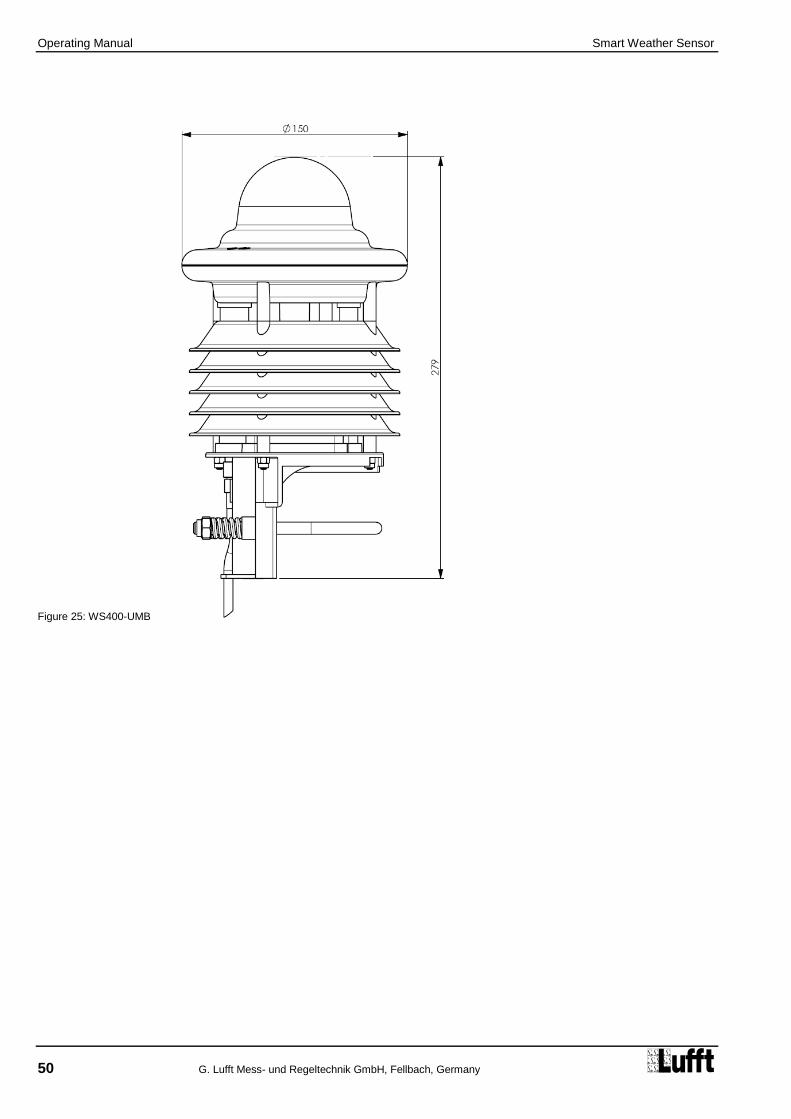
Operating Manual Smart Weather Sensor
50 G. Lufft Mess- und Regeltechnik GmbH, Fellbach, Germany
Figure 25: WS400-UMB

Operating Manual Smart Weather Sensor
G. Lufft Mess- und Regeltechnik GmbH, Fellbach, Germany 51
Figure 26: WS401-UMB

Operating Manual Smart Weather Sensor
52 G. Lufft Mess- und Regeltechnik GmbH, Fellbach, Germany
Figure 27: WS500-UMB

Operating Manual Smart Weather Sensor
G. Lufft Mess- und Regeltechnik GmbH, Fellbach, Germany 53
Figure 28: WS501-UMB
WS502-UMB, WS503-UMB und WS504-UMB are similar.

Operating Manual Smart Weather Sensor
54 G. Lufft Mess- und Regeltechnik GmbH, Fellbach, Germany
Figure 29: WS510-UMB

Operating Manual Smart Weather Sensor
G. Lufft Mess- und Regeltechnik GmbH, Fellbach, Germany 55
Figure 30: WS600-UMB

Operating Manual Smart Weather Sensor
56 G. Lufft Mess- und Regeltechnik GmbH, Fellbach, Germany
Figure 31: WS601-UMB

Operating Manual Smart Weather Sensor
G. Lufft Mess- und Regeltechnik GmbH, Fellbach, Germany 57
Figure 32: WS700-UMB

Operating Manual Smart Weather Sensor
58 G. Lufft Mess- und Regeltechnik GmbH, Fellbach, Germany
14 EC Certificate of Conformity
Product: Smart Weather Sensor
Type: WS200-UMB (Order No.: 8371.U01) WS300-UMB (Order No.: 8372.U01) WS301-UMB (Order No.: 8374.U01) WS302-UMB (Order No.: 8374.U10) WS303-UMB (Order No.: 8374.U11) WS304-UMB (Order No.: 8374.U12) WS310-UMB (Order No.: 8374.U13) WS400-UMB (Order No.: 8369.U01 / 8369.U02) WS401-UMB (Order No.: 8377.U01) WS500-UMB (Order No.: 8373.U01) WS501-UMB (Order No.: 8375.U01) WS502-UMB (Order No.: 8375.U10) WS503-UMB (Order No.: 8375.U11) WS504-UMB (Order No.: 8375.U12) WS510-UMB (Order No.: 8375.U13) WS600-UMB (Order No.: 8370.U01 / 8370.U02) WS601-UMB (Order No.: 8376.U01) WS700-UMB (Order No.: 8380.U01)
We herewith certify that the above mentioned equipment complies in design and construction with the Directives of the European Union and specifically the EMC Directive in accordance with 2004/108/EC and the RoHS Directive 2011/65/EU.
The above mentioned equipment conforms to the following specific EMC Standards:
EN 61000-6-2:2005Part 6-2: Generic Standards - Immunity for Industrial Environments
EN 61000-4-2 (2009-12) ESD
EN 61000-4-3 (2011-04) Radiated electromagnetic field
EN 61000-4-4 (2011-10) Burst
EN 61000-4-5 (2007-06) Surge
EN 61000-4-6 (2009-12) Conducted disturbances, induced by radio- frequency fields
EN 61000-4-8 (2010-11) Power frequency magnetic field immunity
EN 61000-4-16 (2011-09) conducted, common mode disturbances
EN 61000-4-29 (2001-10) Short interruptions and voltage variations on d.c. input
EN 61000-6-3:2007Part 6-4: Generic Standards - Emission Standard for Industrial Environments
EN 55011:2009 + A1:2010 (2011-04) Line-conducted disturbances
IEC / CISPR 11:2009 and changes 1:2010 Class B
prEN 50147-3:2000 Radiated emission
Fellbach, 20.09.2013 Axel Schmitz-Hübsch

Operating Manual Smart Weather Sensor
G. Lufft Mess- und Regeltechnik GmbH, Fellbach, Germany 59
15 Fault Description
Error description Cause - Remedy
Device does not allow polling / does not respond
- Check power supply
- Check interface connection
- Incorrect device ID check ID; devices are delivered with ID 1.
The device measures precipitation but it is not raining
Check that the sensor was installed correctly in accordance with the instructions.
The measured temperature appears too high / measured humidity appears too low
Check the operation of the fan on the underside of the device.
Wind direction values are incorrect Device is not correctly aligned check that the device is aligned to the North.
Device transmits error value 24h (36d)
A channel is being polled that is not available on this device type; e.g. Channel 200 = humidity is being polled on a WS200-UMB.
Device transmits error value 28h (40d)
The device is in the initialization phase following startup the device delivers measurements after approx. 10 seconds.
Device transmits error value 50h (80d)
The device is being operated above the limit of the specified measuring range.
Device transmits error value 51h (81d)
The device is being operated below the limit of the specified measuring range.
Device transmits error value 55h (85d) during wind measurement
The device is unable to execute a valid measurement due to the ambient conditions.
This may be due to the following reasons:
- The device is being operated well above the limit of the specified measuring range
- Very strong horizontal rain or snow
- The wind meter sensors are very dirty clean sensor
- The wind meter sensors are iced over check heating mode in the configuration and check heating function / connection
- There are foreign objects within the measuring section of the wind meter
- One of the wind meter’s sensors is faulty return device to manufacturer for repair
The quality of the wind measurement is not always100%
In normal operation the device should always transmit 90 – 100%. Values up to 50% do not represent a general problem.
When the error value 55h (85d) is transmitted this value is 0%.
If the device permanently transmits values below 50% this may mean that there is a fault.
Device transmits an error value not listed here
This may be due to a number of reasons contact the manufacturer’s technical support department.

Operating Manual Smart Weather Sensor
60 G. Lufft Mess- und Regeltechnik GmbH, Fellbach, Germany
16 Disposal
16.1 Within the EC
The device shall be disposed of in accordance with European Directives 2002/96/EC and 2003/108/EC (waste electrical and electronic equipment).
16.2 Outside the EC
Please comply with the applicable regulations for the proper disposal of waste electrical and electronic equipment in your respective country.
17 Repair / Corrective Maintenance
Please arrange for any faulty equipment to be checked and, if necessary, repaired by the manufacturer exclusively. Do not open the equipment and do not under any circumstances attempt to carry out your own repairs.
In matters of guarantee or repair please contact:
G. Lufft Mess- und Regeltechnik GmbH
Gutenbergstraße 20 70736 Fellbach
P.O. Box 4252 70719 Fellbach
Germany
Phone: +49 711 51822-0 Hotline: +49 711 51822-52 Fax: +49 711 51822-41
E-mail: [email protected]
or your local distributor.
17.1 Technical Support
Our Hotline is available for technical questions via the following e-mail address:
You can also consult frequently asked questions at http://www.lufft.com/ (menu header: SUPPORT / FAQs).

Operating Manual Smart Weather Sensor
G. Lufft Mess- und Regeltechnik GmbH, Fellbach, Germany 61
Figure 33: Connection of the Leaf Wetness Sensor
18 External Sensors
18.1 Leaf Wetness Sensor WLW100
18.1.1 Connection of the Leaf Wetness Sensor
The optional leaf wetness sensor is connected inside the rain gauge module. The cable should not be shortened and be connected with the cable shoes as delivered to avoid contact corrosion.
Unlock funnel by turning it left and lift it off
Insert cable (A)
Connect wires with cable shoes (B) Blank 1 Red 2 White 3
Check that the tipping bucket is free to move; if necessary pull the cable back to the appropriate length
Put funnel back in place and lock it by turning it to the right

Operating Manual Smart Weather Sensor
62 G. Lufft Mess- und Regeltechnik GmbH, Fellbach, Germany
Figure 34: Setting the Leaf Wetness Threshold
18.1.2 Setting the Leaf Wetness Threshold
The leaf wetness sensor will, depending on the degree of wetness on the surface of the sensor leaf, output a voltage between ca. 500mV and 1200mV (UMB-Channel 710). The state wet / dry (UMB- Channel 711) is evaluated from this voltage using an adjustable threshold.
The threshold is pre-set to 580mV (factory setting). It should be checked after installation and, if necessary, adjusted.
Use the UMB Config Tool to measure channel 710 and collect values of the dry sensor for about 10min (see chapter 10.3 Function Test with UMB Config Tool).
The dry leaf value measured should be constant over the measurement interval. We recommend to set the threshold about 20mV higher than the dry leaf voltage:
Example: measured (dry leaf): 577mV threshold setting597mV
The threshold value thus evaluated is set into the configuration using the UMB Config Tool.
Note: We recommend to check the threshold during maintenance and to adjust it if necessary. For the dry leaf measurement the sensor should be cleaned with clear water and carefully dried.

Operating Manual Smart Weather Sensor
G. Lufft Mess- und Regeltechnik GmbH, Fellbach, Germany 63
Figure 35: Setting type of external sensor
18.2 External Temperature and Precipitation Sensors
18.2.1 Connection of Temperature and Precipitation Sensors
Additional external sensor can cover the requirements of special measurement requirements or extend the functionality of Smart Weather Sensors.
Currently the accessory list includes external temperature sensors and the precipitation detection by tipping bucket rain gauge.
One input is available for this extension, so alternatively one temperature sensor or one precipitation sensor may be used.
The connection uses the standard connector plug of the Smart Weather Sensor, so normally the external device will be connected at the end of the cable included with the delivery, in the control cabinet. As this cable is part of the measuring line care shall be taken when designing the cabling to avoid parasitic coupling etc. The cable should be as short as possible. In special cases, e.g. when the external sensor is mounted near to the Smart Weather Sensor while the control cabinet is distant, the installation of an additional distribution box should be considered.
The external sensor is connected to pins 5 and 6 of the connector plug, i.e. the grey and pink wires of the standard cable.
All currently available sensors are unipolar, so the connection sequence is not relevant.
The Smart Weather Sensor must be configured for the selected type of external sensor (temperature or precipitation) to enable the correct evaluation of the measurement data. The selection of the sensor type is done through the UMB Config Tool.
If the data from the channels of the sensor type currently not selected are requested, the device will respond with “invalid channel”.

Operating Manual Smart Weather Sensor
64 G. Lufft Mess- und Regeltechnik GmbH, Fellbach, Germany
Figure 36: Example WS501-UMB and WTB100
18.2.2 External Temperature Sensor
All models of the WS family can be used with an external temperature sensor.
For different application various types of NTC sensor are in supply:
WT1 for temperature acquisition of devices and surfaces
WST1 for mounting in the road surface (road surface temperature)
Mounting / installation of the temperature sensors is shown in the sensor manual.
18.2.3 External Rain Gauge
All models of the WS family without integrated precipitation detection can be used with an external rain gauge. Models WS400-UMB, WS600-UMB, WS401-UMB, WS601-UMB, WS700-UMB with R2S sensor resp. integrated tipping bucket cannot be equipped with an external rain gauge.
The measurement values of the external rain gauge are on the same channels as the data of the internal precipitation sensors of WS400-UMB, WS600-UMB, WS401-UMB, WS601-UMB and WS700-UMB.
The external rain gauge WTB100 uses the same technology as the integrated rain gauge of models WS401-UMB and WS601-UMB.
The resolution of the rain gauge WTB100 can be modified by the reduction ring delivered with the sensor from 0.2mm to 0.5mm.
In principle, all rain sensors with bounce-free reed contact (normally open or normally closed) and with a resolution of 0.1 mm, 0.2 mm, 0.5 mm or 1.0 mm can be used.
Note: To get the correct amount of rain this “mechanical” selection must be also be set in Smart Weather Sensors configuration.
The setting is done with the UMB Config Tool by the same procedure as with WS401-UMB and WS601-UMB (s. Chap.10.2.8).
The WS601/401-UMB’s advices for installation (Chap.7.3.4) and maintenance (Chap.12.1) are as well valid for the external rain gauge.
Example with WS501-UMB and WTB100 without reduction ring:

Operating Manual Smart Weather Sensor
G. Lufft Mess- und Regeltechnik GmbH, Fellbach, Germany 65
19 Appendix
19.1 Channel List Summary
The channel assignment applies to online data requests in binary and ASCII protocol.
UMB Channel Measuring Range
act min max avg special Measurement Variable
(float32) min max unit
Temperatures
100 120 140 160 temperature -50.0 60.0 °C
105 125 145 165 temperature -58.0 140.0 °F
101 external temperature -40.0 80.0 °C
106 external temperature -40.0 176.0 °F
110 130 150 170 dewpoint -50.0 60.0 °C
115 135 155 175 dewpoint -58.0 140.0 °F
111 wind chill temperature -60.0 70.0 °C
116 wind chill temperature -76.0 158.0 °F
114 wet bulb temperature -50.0 60.0 °C
119 wet bulb temperature -58.0 140.0 °F
112 wind heater temp. -50.0 150.0 °C
113 R2S heater temp. -50.0 150.0 °C
117 wind heater temp. -58.0 302.0 °F
118 R2S heater temp. -58.0 302.0 °F
Humidity
200 220 240 260 relative humidity 0.0 100.0 %
205 225 245 265 absolute humidity 0.0 1000.0 g/m³
210 230 250 270 mixing ratio 0.0 1000.0 g/kg
Enthalpy
215 specific enthalpy -100.0 1000.0 kJ/kg
Pressure
300 320 340 360 abs. air pressure 300 1200 hPa
305 325 345 365 rel. air pressure 300 1200 hPa
Air Density
310 air density 0.0 3.0 kg/m³
Wind
vect. avg
400 420 440 460 480 wind speed 0 75.0 m/s
405 425 445 465 485 wind speed 0 270.0 km/h
410 430 450 470 490 wind speed 0 167.8 mph
415 435 455 475 495 wind speed 0 145.8 kts
401 wind speed fast 0 75.0 m/s
406 wind speed fast 0 270.0 km/h
411 wind speed fast 0 167.8 mph
416 wind speed fast 0 145.8 kts
403 wind speed standard deviation 0 75.0 m/s
413 wind speed standard deviation 0 167.8 mph
500 520 540 580 wind direction 0 359.9 °
501 wind direction fast 0 359.9 °
502 wind direction corr. 0 359,9 °
503 wind direction standard deviation 0 359.0 °
805 wind value quality 0 100.0 %
806 wind value quality (fast) 0 100.0 %
Compass
510 compass heading 0 359 °

Operating Manual Smart Weather Sensor
66 G. Lufft Mess- und Regeltechnik GmbH, Fellbach, Germany
Precipitation Quantity Range Unit
600 float32 Precipitation Quantity - Absolute 0 … 100000 liters/m²
620 float32 Precipitation Quantity - Absolute 0 … 100000 mm
640 float32 Precipitation Quantity - Absolute 0 … 3937 inches
660 float32 Precipitation Quantity - Absolute 0 … 3937008 mil
605 float32 Precipitation Quantity - Differential 0 … 100000 liters/m²
625 float32 Precipitation Quantity - Differential 0 … 100000 mm
645 float32 Precipitation Quantity - Differential 0 … 3937 inches
665 float32 Precipitation Quantity - Differential 0 … 3937008 mil
Precipitation Type
700 uint7 Precipitation Type
0 = No precipitation
40 = unspecified precipitation 60 = Liquid precipitation, e.g. rain 70 = Solid precipitation, e.g. snow
Precipitation Intensity Range unit
800 float32 Precipitation Intensity 0 … 200.0 l/m²/h
820 float32 Precipitation Intensity 0 … 200.0 mm/h
840 float32 Precipitation Intensity 0 … 7.874 in/h
860 float32 Precipitation Intensity 0 … 7874 mil/h
act min max avg special Measurement Variable
(float32) min max unit
Global Radiation
900 920 940 960 Global Radiation 0 1400 W/m²
Leaf Wetness
710 730 750 770 Leaf Wetness mV 0.0 1500.0 mV
711 Leaf Wetness State 0 = dry 1 = wet
Service Channels
10000 Supply Voltage V 0.0 50.0 V
11000 Rain Drop Volume µl 0.0 500.0 µl
Note: The channels which are actually available are dependent on the WSxxx-UMB type in use.

Operating Manual Smart Weather Sensor
G. Lufft Mess- und Regeltechnik GmbH, Fellbach, Germany 67
19.2 Channel List Summary per TLS2002 FG3
The following channels are available specifically for data requests for further processing in TLS format. These channels are only available in the UMB-Binary protocol.
DE Type
UMB Channel
Meaning Format Range Resolution Coding
48 1048 Result message Air Temperature LT
16 bit -30 ... +60°C
0.1°C 60.0 = 600d = 0258h 0.0 = 0d = 0000h -0.1 = -1d = FFFFh -30.0 = -300d = FED4h
53 1053 Result message Precipitation Intensity NI
16 bit 0 ... 200 mm/h
0.1 mm/h 0.0 = 0d = 0000h 200.0 = 2000d = 07D0h
54 1054 Result message Air Pressure LD
16 bit 800...1200 hPa
1 hPa 800 = 800d = 0320h 1200 = 1200d = 04B0h
55 1055 Result message Relative Humidity RLF
8 bit 10% ... 100%
1% RH 10% = 10d = 0Ah 100% = 100d = 64h
56 1056 Result message Wind Direction WR
16 bit 0 ... 359° 1° 0° (N) = 0d = 0000h 90° (O) = 90d = 005Ah 180° (S) = 180d = 00B4h 270° (W) = 270d = 010Eh FFFFh = not definable
57 1057 Result message Wind Speed. (average) WGM
16 bit 0.0 ... 60.0 m/s
0.1 m/s 0.0 = 0d = 0000h 60.0 = 600d = 0258h
64 1064 Result message Wind Speed (peak) WGS
16 bit 0.0 ... 60.0 m/s
0.1 m/s 0.0 = 0d = 0000h 60.0 = 600d = 0258h
66 1066 Result message Dewpoint Temperature TPT
16 bit -30 ... +60°C
0.1°C 60.0 = 600d = 0258h 0.0 = 0d = 0000h -0.1 = -1d = FFFFh -30.0 = -300d = FED4h
71 1071 Result message Precipitation Type NS
8 bit 0 = No precipitation 40 = unspecified precipitation 60 = Liquid precipitation, e.g. rain 70 = Solid precipitation, e.g. snow
Note: The channels which are actually available are dependent on the WSxxx-UMB type in use.
The previous channels 1153 and 1253 are no longer supported. Channels 840 and 860 can be used in their place.

Operating Manual Smart Weather Sensor
68 G. Lufft Mess- und Regeltechnik GmbH, Fellbach, Germany
19.3 Communication in Binary Protocol
Only one example of an online data request is described in this operating manual. Please refer to the current version of the UMB Protocol for all commands and the exact mode of operation of the protocol (available for download at www.lufft.com).
Note: Communication with the sensor takes place in accordance with the master-slave principle, i.e. there may only be ONE requesting unit on a network.
19.3.1 Framing
The data frame is constructed as follows:
SOH Control character for the start of a frame (01h); 1 byte
<ver> Header version number, e.g.: V 1.0 <ver> = 10h = 16d; 1 byte
<to> Receiver address; 2 bytes
<from> Sender address; 2 bytes
<len> Number of data bytes between STX and ETX; 1 byte
STX Control character for the start of payload transmission (02h); 1 byte
<cmd> Command; 1 byte
<verc> Version number of the command; 1 byte
<payload> Data bytes; 0 – 210 bytes
ETX Control character for the end of payload transmission (03h); 1 byte
<cs> Check sum, 16 bit CRC; 2 bytes
EOT Control character for the end of the frame (04h); 1 byte
Control characters: SOH (01h), STX (02h), ETX (03h), EOT (04h).
19.3.2 Addressing with Class and Device ID
Addressing takes place by way of a 16 bit address. This breaks down into a Class ID and a Device ID.
Address (2 bytes = 16 bit)
Bits 15 – 12 (upper 4 bits) Bits 11 – 8 (middle 4 bits)
Bits 7 – 0 (lower 8 bits)
Class ID (0 to 15) Reserve Device ID (0 – 255)
0 Broadcast 0 Broadcast
7 Smart Weather Sensor
(WS200-UMB – WS600-UMB) 1 - 255 Available
15 Master or control devices
ID = 0 is provided as broadcast for classes and devices. Thus it is possible to transmit a broadcast on a specific class. However this only makes sense if there is only one device of this class on the bus; or in the case of a command, e.g. reset.
1 2 3 - 4 5 - 6 7 8 9 10 11 ... (8 + len)
optional 9 + len
10 + len 11 + len
12 + len
SOH <ver> <to> <from> <len> STX <cmd> <verc> <payload> ETX <cs> EOT

Operating Manual Smart Weather Sensor
G. Lufft Mess- und Regeltechnik GmbH, Fellbach, Germany 69
19.3.3 Examples for Creating Addresses
If, for example, you want to address WS400-UMB with the device ID 001, this takes place as follows:
The class ID for the Smart Weather Sensor is 7d = 7h; the device ID is e.g. 001d = 001h
Putting the class and device IDs together gives the address 7001h (28673d).
19.3.4 Example of a Binary Protocol Request
If, for example, a Smart Weather Sensor with the device ID 001 is to be polled from a PC for the current temperature, this takes place as follows:
Sensor:
The class ID for the Smart Weather Sensors 7 = 7h;
The device ID is 001 = 001h
Putting the class and device IDs together gives a target address of 7001h.
PC:
The class ID for the PC (master unit) is 15 = Fh; the PC ID is e.g. 001d = 01h.
Putting the class and device IDs together gives a sender address of F001h.
The length <len> for the online data request command is 4d = 04h;
The command for the online data request is 23h;
The version number of the command is 1.0 = 10h.
The channel number is in <payload>; as can be seen from the channel list (page 65), the current temperature in °C in the channel is 100d = 0064h.
The calculated CRC is D961h.
The request to the device:
SOH <ver> <to> <from> <len> STX <cmd> <verc> <channel> ETX <cs> EOT
1 2 3 4 5 6 7 8 9 10 11 12 13 14 15 16
01h 10h 01h 70h 01h F0h 04h 02h 23h 10h 64h 00h 03h 61h D9h 04h
The response from the device:
SOH <ver> <to> <from> <len> STX <cmd> <verc> <status> <channel> <typ>
1 2 3 4 5 6 7 8 9 10 11 12 13 14
01h 10h 01h F0h 01h 70h 0Ah 02h 23h 10h 00h 64h 00h 16h
<value> ETX <cs> EOT
15 16 17 18 19 20 21 22
00h 00h B4h 41h 03h C6h 22h 04h
Interpretation of the response:
<status> = 00h device o.k. (≠ 00h signifies error code; see page 70)
<typ> = Data type of the following value; 16h = float (4 bytes, IEEE format)
<value> = 41B40000h as a float value corresponds to 22.5
The temperature is therefore 22.5°C.
The correct data transmission can be checked with the aid of the check sum (22C6h).
Note: Little Endian (Intel, low byte first) applies when transmitting word and float variables of addresses or the CRC, for example. This means first the LowByte and then the HighByte.

Operating Manual Smart Weather Sensor
70 G. Lufft Mess- und Regeltechnik GmbH, Fellbach, Germany
19.3.5 Status and Error Codes in Binary Protocol
If a measurement request delivers the <status> 00h, the sensor is working correctly. You can find a complete list of additional codes in the description of the UMB protocol.
Extract from list:
<status> Description
00h (0d) Command successful; no error; all o.k.
10h (16d) Unknown command; not supported by this device
11h (17d) Invalid parameter
24h (36d) Invalid channel
28h (40d) Device not ready; e.g. initialization / calibration running
50h (80d) Measurement variable (+offset) is outside the set display range
51h (81d)
52h (82d) Measurement value (physical) is outside the measuring range (e.g. ADC over range)
53h (83d)
54h (84d) Error in measurement data or no valid data available
55h ( 85d) Device / sensor is unable to execute valid measurement due to ambient conditions
19.3.6 CRC Calculation
CRC is calculated according to the following rules:
Norm: CRC-CCITT
Polynomial: 1021h = x16
+ x12
+ x5 + 1 (LSB first mode)
Start value: FFFFh
You can find further information in the description of a CRC calculation in UMB Protocol.
19.3.7 Data Request in Power Saving Mode 2
When in power saving mode2 the processor of the Smart Weather Sensor will be usually in sleep state. For the acquisition of measurement data a certain command sequence and a certain timing is required:
„Wake Up“ bei sending a <Break>, any character or any telegram (a telegram will not be properly detected and get no response, because the UART is just starting)
1000msec pause for the processor start up
Activation of the measurement cycle by (any) valid telegram addressed to this device
2000msec pause for the execution of the measurement sequence
Request of the measurement results
Example of a Request Sequence:
Command Data Request (0x23), Channel 100
No response
Wait 1 sec
Command Data Request (0x23), Channel 100
Discard data
Wait 2 sec
CommandMultiData Request (0x2F), Ch. 100, 200, 300, 620, 605, 700
Store data

Operating Instructions Smart Weather Sensor
G. Lufft Mess- und Regeltechnik GmbH, Fellbach, Germany 71
19.4 Communication in ASCII Protocol
Text-based communication with devices is possible using ASCII protocol.
To do this, in the device configuration, interface settings, the protocol mode must be set to ASCII (see page 30).
ASCII protocol is network-compatible and serves exclusively for online data requests. The device will not respond to incomprehensible ASCII commands.
Note: The use of binary protocol is recommended for lengthy transmission routes (e.g. network, GPRS/UMTS), as ASCII protocol is unable to detect transmission errors (not CRC-secured).
Note: TLS channels are not available in ASCII protocol.
19.4.1 Structure
An ASCII command is introduced by the ‘&’ character and completed by the CR (0Dh) sign. There is a space character (20h) between the individual blocks in each case; this is represented by an underscore character ‘_’. Characters that represent an ASCII value are in ordinary inverted commas.
19.4.2 Summary of ASCII Commands
Command Function BC AZ
M Online data request l
X Switches to binary protocol k
R Triggers software reset k
D Software reset with delay k
I Device information k
These operating instructions describe the online data request only. You can find the description of the other commands in the UMB protocol.
19.4.3 Online Data Request (M)
Description: By way of this command, a measurement value is requested from a specific channel.
Request: ‘&’_<ID>5_‘M’_<channel>
5 CR
Response: ‘$’_<ID>5_‘M’_<channel>
5_<value>
5 CR
<ID>5 Device address (5 decimal places with leading zeros)
<channel>5 Indicates the channel number (5 decimal places with leading zeros)
<value>5 Measurement value (5 decimal places with leading zeros); a measurement
value standardized to 0 – 65520d. Various error codes are defined from 65521d – 65535d.
Example:
Request: &_28673_M_00100
By way of this request, channel 100 of the device with address 28673 is interrogated (Smart Weather Sensor with device ID 001).
Response: $_28673_M_00100_34785
This channel outputs a temperature from –50 to +60°C, which is calculated as follows:
0d corresponds to -50°C
65520d corresponds to +60°C
36789d corresponds to [+60°C – (-50°C)] / 65520 * 34785 +(-50°C) = 8.4°C
Note: TLS channels are not available in ASCII protocol.

Operating Manual Smart Weather Sensor
72 G. Lufft Mess- und Regeltechnik GmbH, Fellbach, Germany
19.4.4 Standardization of Measurement Values in ASCII Protocol
The standardization of measurement values from 0d – 65520d corresponds to the measuring range of the respective measurement variable.
Measurement Variable Measuring Range
Min Max Unit
Temperature
Temperature
Dew point
Wet Bulb Temperature
-50.0 60.0 °C
-58.0 140.0 °F
External Temperature -40.0 80.0 °C
-40.0 176.0 °F
Wind chill temperature -60.0 70.0 °C
-76.0 158.0 °F
Humidity
Relative humidity 0.0 100.0 %
Absolute humidity
Mixing ratio 0.0 1000.0
g/m³
g/kg
Specific Enthalpy -100.0 1000.0 kJ/kg
Pressure
Relative air pressure
Absolute air pressure 300.0 1200.0 hPa
Air Density
air density 0.0 3.0 kg/m³
Wind
Wind speed
0.0 75.0 m/s
0.0 270.0 km/h
0.0 167.8 mph
0.0 145.8 kts
Wind direction 0.0 359.9 °
wind value quality 0.0 100.0 %
Rain
Quantity
0.0 6552.0 litres / m²
0.0 6552.0 mm
0.0 257.9 inches
0.0 257952.7 mil
Quantity since last request
0.0 655.2 litres / m²
0.0 655.2 mm
0.0 25.79 inches
0.0 25795.2 mil
Precipitation type
0 = No precipitation
40 = Precipitation 60 = Liquid precipitation, e.g. rain 70 = Solid precipitation, e.g. snow
Precipitation intensity
0.0 200.0 l/m²/h
0.0 200.0 mm/h
0.0 7.874 in/h
0.0 7874 mil/h
Global Radiation
Global Radiation 0.0 1400.0 W/m²
Leaf Wetness
Leaf Wetness mV 0.0 1500.0 mV
Leaf Wetness State 0 = dry 1 = wet

Operating Instructions Smart Weather Sensor
G. Lufft Mess- und Regeltechnik GmbH, Fellbach, Germany 73
19.4.5 Error Codes in the ASCII Protocol
Various error codes are defined from 65521d – 65535d in addition to the standardisation for the transmission of measurement values.
<code> Description
65521d Invalid Channel
65523d Value Overflow
65524d Value Underflow
65525d Error in measurement data or no valid data available
65526d Device / sensor is unable to execute valid measurement due to ambient conditions
65534d Invalid Calibration
65535d Unknown Error

Operating Manual Smart Weather Sensor
74 G. Lufft Mess- und Regeltechnik GmbH, Fellbach, Germany
19.5 Communication in Terminal Mode
It is possible to communicate with a device in a very simple text-based manner using the terminal mode.
To do this, in the device configuration, interface settings, the protocol mode must be set to terminal (see page 30).
Note: In the case of communication in the terminal mode, only one single unit may be connected to the interface, as this protocol is NOT network-compatible. It is used for very simple measurement value requests.
Note: The use of binary protocol is recommended for lengthy transmission routes (e.g. network, GPRS/UMTS), as it is not possible to detect transmission errors in terminal mode (not CRC-secured).
Note: In the terminal mode, measurement values are not available in all units. Furthermore, status and error messages are not transmitted.
19.5.1 Structure
A terminal consists of an ASCII character and a numeric character. The command is completed with the <CR> sign. There is no echo on entry.
The individual values in the response are separated by a semi-colon (;). The response is completed with <CR><LF>.
An invalid terminal command is acknowledged with ‘FAILED’. Control commands are acknowledged with ‘OK’.
The command to which the response relates is given at the beginning of each response.
Note: No response times are specified in the terminal mode.

Operating Instructions Smart Weather Sensor
G. Lufft Mess- und Regeltechnik GmbH, Fellbach, Germany 75
19.5.2 Terminal Commands
The terminal commands transmit the following values or have the following functions:
E0<CR> Temperature in °C Ta C (Channel 100)
Dew point temperature in °C Tp C (Channel 110) Wind chill temperature in °C Tw C (Channel 111) Relative humidity in % Hr P (Channel 200) Relative air pressure in hPa Pa H (Channel 305) Wind speed in m/s Sa M (Channel 400) Wind direction in ° Da D (Channel 500) Precipitation quantity in mm Ra M (Channel 620) Precipitation type Rt N (Channel 700) Precipitation intensity in mm/h Ri M (Channel 820)
E1<CR> Temperature in °F Ta F (Channel 105)
Dew point temperature in °F Tp F (Channel 115) Wind chill temperature in °F Tw F (Channel 116) Relative humidity in % Hr P (Channel 200) Relative air pressure in hPa Pa H (Channel 305) Wind speed in mph Sa S (Channel 410) Wind direction in ° Da D (Channel 500) Precipitation quantity in inches Ra I (Channel 640) Precipitation type Rt N (Channel 700) Precipitation intensity in inches/h Ri I (Channel 840)
E2<CR> Act. wind speed in m/s Sa M (Channel 400)
Min. wind speed in m/s Sn M (Channel 420) Max. wind speed in m/s Sx M (Channel 440) Avg. wind speed in m/s Sg M (Channel 460) Vct. wind speed in m/s Sv M (Channel 480) Act. wind direction in ° Da D (Channel 500) Min. wind direction in ° Dn D (Channel 520) Max. wind direction in ° Dx D (Channel 540) Vct. wind direction in ° Dv D (Channel 580)
E3<CR> Act. wind speed in mph Sa S (Channel 410)
Min. wind speed in mph Sn S (Channel 430) Max. wind speed in mph Sx S (Channel 450) Avg. wind speed in mph Sg S (Channel 470) Vct. wind speed in mph Sv S (Channel 490) Act. wind direction in ° Da D (Channel 500) Min. wind direction in ° Dn D (Channel 520) Max. wind direction in ° Dx D (Channel 540) Vectorial wind direction in ° Dv D (Channel 580)
E4<CR> Act. Compass heading in ° Ca D (Channel 510)
Act. Global Radiation in W/m² Ga W (Channel 900) Min. Global Radiation in W/m² Gn W (Channel 920) Max. Global Radiation in W/m² Gx W (Channel 940) Avg. Global Radiation in W/m² Gg W (Channel 960) Act. Specific Enthalpy in KJ/Kg Ea J (Channel 215) Act. Wet Bulb Temperature in °C Ba C (Channel 114) Act. Wet Bulb Temperature in °F Ba F (Channel 119) Act. Air Density in kg/m³ Ad G (Channel 310)
E5<CR> act. Leaf Wetness mV La X (Channel 710)
act. Leaf Wetness State Lb X (Channel 711) external temperature (act) °C Te C (Channel 101) external temperature (act) °F Te F (Channel 106) Reserve Xx X Reserve Xx X Reserve Xx X Reserve Xx X Reserve Xx X
Mx<CR> Displays the same values as Ex<CR>, but without additional information such as the
measurement variable and unit
I0<CR> Serial number; date of manufacture; project number; parts list version;
SPLAN version; hardware version; firmware version; E2 version; device version
I1<CR> Outputs the device description

Operating Manual Smart Weather Sensor
76 G. Lufft Mess- und Regeltechnik GmbH, Fellbach, Germany
R0<CR> Executes a device reset
R1<CR> Resets the accumulated rain quantity and executes a device reset
X0<CR> Temporarily switches to UMB binary protocol
Examples:
E0<CR> E0;Ta+024.9C;Tp+012.2C;Tw+026.8C;Hr+045.0P;Pa+0980.6H; Sa+005.1M;Da+156.6D;Ra+00042.24M;Rt+060N;Ri+002.6M;
M0<CR> M0;+024.9;+012.2;+026.8;+045.0;+0980.6; +005.1;+156.6;+00042.24;+060;+002.6;
E2<CR> E2;Sa+005.1M;Sn+001.1M;Sx+007.1M;Sg+005.1M;Sv+005.0M; Da+156.6D;Dn+166.6D;Dx+176.6D;Dv+156.6D;
M2<CR> M2;+005.1;+001.1;+007.1;+005.1;+005.0; +156.6;+166.6;+176.6;+156.6;
I0<CR> I0;001;0109;0701;004;005;001;016;011;00002;<CR><LF>
R0<CR> R0;OK;<CR><LF>

Operating Instructions Smart Weather Sensor
G. Lufft Mess- und Regeltechnik GmbH, Fellbach, Germany 77
Figure 37: Sensor Configuration SDI-12
Figure 38: Sensor Configuration SDI-12 Units
19.6 Communication in SDI-12 Mode
The communication in the SDI-12 mode of the Smart Weather Sensor is conforming to the standard defined in ‚SDI-12 A Serial-Digital Interface Standard for Microprocessor-Based Sensors Version 1.3 January 12, 2009‘ . The device may be operated in bus mode together with other SDI-12 sensors, connected to one SDI master (logger).
19.6.1 Preconditions for SDI-12 Operation
As the interface settings defined in the SDI-12 standard are significantly different from the UMB default settings the related parameters have to be set properly by the UMB Config Tool (latest version!).
The protocol mode of the device has to be set to “SDI-12”. This will automatically set the baud rate to 1200.
Measurement data can be transmitted alternatively in metric or US units. The selection is done by the UMB Config Tool.
Metric units US units
Note: Please observe notes on page 25 when connecting a SDI12 data logger!

Operating Manual Smart Weather Sensor
78 G. Lufft Mess- und Regeltechnik GmbH, Fellbach, Germany
When operating the device in SDI-12 mode it is basically no more possible to access the device with the UMB Config Tool, due to the different interface parameter settings. To enable configuration access nevertheless the interface is operated in standard UMB mode (19200 8N1) for the first 5 seconds(*) after reset / power on. During this time the UMB device ID, if unequal 1, is set to 200, so access will be possible even if the device ID is unknown. If a valid UMB telegram is received within this 5 sec, the device will stay in UMB mode for the configured time out (several minutes) so that the configuration can be modified.
Connect the PC to the Smart Weather Sensor through an RS-485 converter
Start the UMB Config Tool and create a WSxxx-UMB with the address (1 or 200) of the actual device and activate at least one sensor. Start the measurement (will report connection error at first)
Reset the device (Power off / on)
When measurement values are received the measurement can be terminated, the interface is now open for configuration.
(*) Remark: The 5 seconds UMB communication are available from program start. Under consideration of the operating system start, where no communication is possible, the device will be ready for SDI12 requests after 7.0 – 7.5 seconds.
This timing only applies in case of cold start after power on or reset. This phase will not occur after “wake up” in Power Saving Mode 2. In this case the device will respond within the time defined by the SDI12 standard.

Operating Instructions Smart Weather Sensor
G. Lufft Mess- und Regeltechnik GmbH, Fellbach, Germany 79
19.6.2 Command Set
For details of the SDI-12 protocol please refer to the above mentioned standard document.
Following commands are available for devices of the WS family:
Note: The examples in the following sections use italics to print the requests from the logger
(0V!)
Command Function
?! Address search (Wildcard request, one device only on bus!)
a! Request device active?
aI! Request device identification
aAb! Address change to b ( 0 … 9, A …Z, a … z)
aM! Measurement basic minimal data set
aM1! Measurement temperatures
aM2! Measurement humidity
aM3! Measurement air pressure
aM4! Measurement wind
aM5! Measurement compass
aM6! Measurement precipitation
aM7! Measurement global radiation
aM8! Measurement external temperature
aMC! Measurement, basic minimal data set, transmit values with CRC
aMC1! ... aMC8!
Measurement (assignment of values as for aMn! commands), transmit values with CRC
aC! Concurrent measurement, full basic data set
aC1! ... aC8!
Concurrent measurement, assignment of values as for aMn! commands, partly extended data sets
aCC! Concurrent measurement, transmit values with CRC
aCC1! ... aCC8!
Concurrent measurement, assignment of values as for aMn! commands, partly extended data sets, transmit values with CRC
aD0! Data request buffer 0
aD1! Data request buffer 1
aD2! Data request buffer 2
aD3! Data request buffer 3
aD4! Data request buffer 4
aR0! Data request from continuous measurement, data set 0
aR1! Data request from continuous measurement, data set 1
aR2! Data request from continuous measurement, data set 2
aR3! Data request from continuous measurement, data set 3
aR4! Data request from continuous measurement, data set 4
aRC0! Data request from continuous measurement, data set 0 with CRC
aRC1! Data request from continuous measurement, data set 1 with CRC
aRC2! Data request from continuous measurement, data set 2 with CRC
aRC3! Data request from continuous measurement, data set 3 with CRC
aRC4! Data request from continuous measurement, data set 4 with CRC
aV! Command verification: Evaluate sensor status and heating temperatures, data request with aD0!, aD1!
aXU<m/u>! Change the unit system for SDI data
aXH+nnnn! Set local altitude of the device for calculation of rel. air pressure

Operating Manual Smart Weather Sensor
80 G. Lufft Mess- und Regeltechnik GmbH, Fellbach, Germany
Command Function
aXD+nnn.n! Set local compass deviation
aXL<n/s/w>! Set power saving mode
aXMn! Set the heating mode of the device
aXA<t/p/w>+nn! Integration time for average and min/max evaluation
aXC! Clear the abs. precipitation amount ( includes a device reset)
aXR! Device reset
The composition of the minimal and the full basic data set depends on the variant (WS200-UMB ... WS700-UMB) of the device in question (see below). The same applies to the availability of the additional measurement commands (aM1!, aC1! etc.)
Due the applied measurement processes the devices of the WS family will, different from other sensors described in the SDI-12 document, in normal operation mode always measure continuously. This causes some special properties while in this mode:
The device does not need a “Wakeup” and does not have a sleep mode. So the reactions to “Break” signals and any related timings are inapplicable. “Break” will be ignored by WS devices.
Data requested with M- or C- commands are always available immediately. The device will always respond with a000n resp. a000nn. This means the device will not
send any service request and will ignore measurement abort signals. The logger should request the data immediately.
M- and C- command only differ in the number of values made available in the buffers (in both cases the maximum permitted by the standards of 9 resp. 20).
We recommend to use the commands for continuous measurement (R-commands) to request the data.
When in power saving mode 2 the device will wake up by a „Break“ signal. Other functions of the „Break“ signal are not implemented.
When in power saving mode 2 the device responds to M or C commands with a002n resp. a002nn and holds the data available within 2 seconds. It will not send a
service request, signals to abort the measurement are ignored.
For the reduced data set in power saving mode 2 a unified data buffer structure for all device models has been defined. Depending on the individual model unused channels will be set to the “invalid” marker 999.9.

Operating Instructions Smart Weather Sensor
G. Lufft Mess- und Regeltechnik GmbH, Fellbach, Germany 81
19.6.3 Address Configuration
UMB Device-ID and SDI-12 Address are connected, but the different address ranges and the fact, that UMB ID’s are integer numbers, while SDI-12 addresses are ASCII characters, have to be considered.
The SDI-12 address is built from the UMB device ID as follows:
UMB Device ID 1 (default) corresponds to SDI-12 Address ‘0’ (SDI-12 default).
Changing the SDI12 address by SDI12 setting command also modifies the UMB device ID accordingly.
Valid Address Ranges:
UMB (dec) SDI-12 (ASCII)
1 to 10 ‘0’ to ‘9’
18 to 43 ‘A’ to ‘Z’
50 to 75 ‘a’ to ‘z’
19.6.4 Data Messages
In the interest of simplified evaluation the assignment of measurement values to data buffers ‘0’ ... ‘9’ has been defined unified for all measurement commands. For this reason the responses to C-requests have been restricted to 35 characters, not using the 75 characters permitted for these requests
Currently buffers ‘0’ to ‘4’ are in use.
As with M-requests max. 9 values may be transmitted; the base data set of 9 values has been assigned to buffers ‘0’ and ‘1’. Buffers ‘2’ to ‘4’ contain further measurement values. This definition guaranties the compatibility to loggers designed according to older versions of the SDI-12 standard.
The buffer assignment depends on the device variant (WS200-UMB ... WS700-UMB).
The complete set of measurement values, as defined for the UMB protocol has been made available also in the SDI-12 environment. They can be accessed using the additional M and C commands (aM1! ... aM8!, aMC1! ... aMC8!, aC1! ... aC8!, aCC1! ... aCC8!) (see below).
If the measurement value is not available for some reason, e.g. sensor failure, this is indicated by a value of +999.0. or -999.9 The logger can then evaluate the reason of failure by a aV! Verification request. The following tables show the measurement values in the sequence they are arranged in the telegram (see example).
Depending on the configuration of the device the values will be transmitted in metric or US units.
Note: The configured system of units is not indicated in the data messages. The logger may request this setting with the I-command and adjust the evaluation of the data messages accordingly
Example: M Request from a WS600-UMB
0M!
00009<CR><LF> 9 measurement values are available
0D0!
0+13.5+85.7+1017.0+2.5+3.7<CR><LF>
Air temperature 13.5°C, rel. humidity 85.7%, rel. air pressure 1017hPa avg. wind speed 2.5m/s, max wind speed 3.7m/s.
0D1!
0+43.7+9.8+60+4.4<CR><LF>
Wind direction 43.7° wet bulb temperature 9.8°C, type of precipitation 60 (rain), precipitation intensity 4.4mm/h

Operating Manual Smart Weather Sensor
82 G. Lufft Mess- und Regeltechnik GmbH, Fellbach, Germany
Example: C Request from a WS600-UMB
0M!
000020<CR><LF> 20 measurement values are available
0D0!
0+13.5+85.7+1017+2.5+3.7<CR><LF>
air temperature 13.5°C, rel. humidity 85.7%, rel. air pressure 1017hPa avg. wind speed 2.5m/s, max wind speed 3.7m/s.
0D1!
0+43.7+9.8+60+4.4<CR><LF>
wind direction 43.7° wet bulb temperature 9.8°C, type of precipitation 60 (rain), precipitation intensity 4.4mm/h
0D2! 0+11.2+10.3+1.10<CR><LF>
dewpoint 11.2°C, wind chill temperature 10,3°C diff. precipitation 1.10mm
0D3! 0+3.2+0.0+3.5+100.0<CR><LF>
act. wind speed 3,2m/s, min. wind speed 0.0 m/s vect. avg. wind speed 3.5m/s, quality of wind values 100%
0D4! 0+43.7+41.3+45.7+29.3<CR><LF>
act. wind direction 43,7°, min. wind direction 41,3°, max. wind direction 45,7°, specific enthalpy29,3kJ/kg
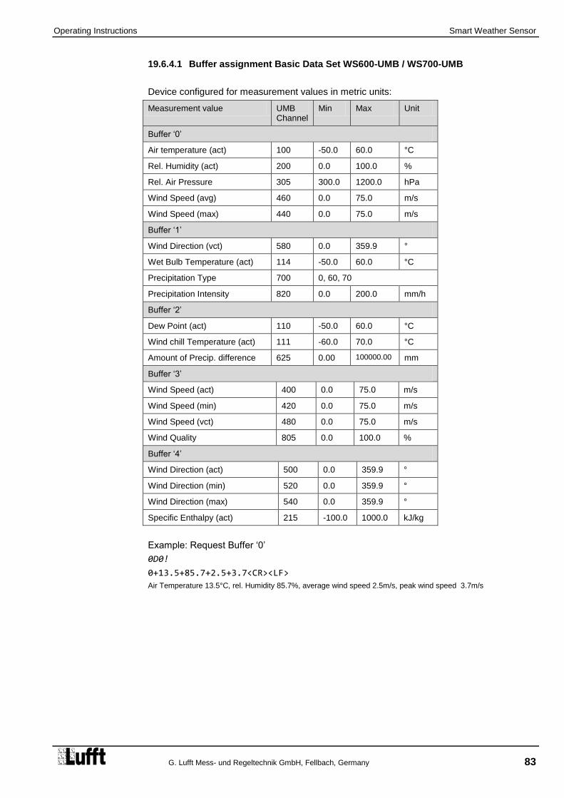
Operating Instructions Smart Weather Sensor
G. Lufft Mess- und Regeltechnik GmbH, Fellbach, Germany 83
19.6.4.1 Buffer assignment Basic Data Set WS600-UMB / WS700-UMB
Device configured for measurement values in metric units:
Measurement value UMB Channel
Min Max Unit
Buffer ‘0’
Air temperature (act) 100 -50.0 60.0 °C
Rel. Humidity (act) 200 0.0 100.0 %
Rel. Air Pressure 305 300.0 1200.0 hPa
Wind Speed (avg) 460 0.0 75.0 m/s
Wind Speed (max) 440 0.0 75.0 m/s
Buffer ‘1’
Wind Direction (vct) 580 0.0 359.9 °
Wet Bulb Temperature (act) 114 -50.0 60.0 °C
Precipitation Type 700 0, 60, 70
Precipitation Intensity 820 0.0 200.0 mm/h
Buffer ‘2’
Dew Point (act) 110 -50.0 60.0 °C
Wind chill Temperature (act) 111 -60.0 70.0 °C
Amount of Precip. difference 625 0.00 100000.00 mm
Buffer ‘3’
Wind Speed (act) 400 0.0 75.0 m/s
Wind Speed (min) 420 0.0 75.0 m/s
Wind Speed (vct) 480 0.0 75.0 m/s
Wind Quality 805 0.0 100.0 %
Buffer ‘4’
Wind Direction (act) 500 0.0 359.9 °
Wind Direction (min) 520 0.0 359.9 °
Wind Direction (max) 540 0.0 359.9 °
Specific Enthalpy (act) 215 -100.0 1000.0 kJ/kg
Example: Request Buffer ‘0’
0D0!
0+13.5+85.7+2.5+3.7<CR><LF>
Air Temperature 13.5°C, rel. Humidity 85.7%, average wind speed 2.5m/s, peak wind speed 3.7m/s

Operating Manual Smart Weather Sensor
84 G. Lufft Mess- und Regeltechnik GmbH, Fellbach, Germany
Device configured for measurement values in US units:
Measurement Value UMB Channel
Min Max Unit
Buffer ‘0’
Air Temperature (act) 105 -58.0 140.0 °F
Rel. Humidity (act) 200 0.0 100.0 %
Rel. Air Pressure 305 300.0 1200.0 hPa
Wind Speed (avg) 470 0.0 167.8 mph
Wind Speed (max) 450 0.0 167.8 mph
Buffer ‘1’
Wind Direction (vct) 580 0.0 359.9 °
Wet Bulb Temperature (act) 119 -58.0 140.0 °F
Precipitation Type 700 0, 60, 70
Precipitation Intensity 840 0.000 7.874 in/h
Buffer ‘2’
Dew Point (act) 115 -58.0 140.0 °F
Wind chill Temperature (act) 116 -76.0 158.0 °F
Amount of Precip. difference 645 0.0000 3937.0000 in
Buffer ‘3’
Wind Speed (act) 410 0.0 167.8 mph
Wind Speed (min) 430 0.0 167.8 mph
Wind Speed (vct) 490 0.0 167.8 mph
Wind Quality 805 0.0 100.0 %
Buffer ‘4’
Wind Direction(act) 500 0.0 359.9 °
Wind Direction (min) 520 0.0 359.9 °
Wind Direction (max) 540 0.0 359.9 °
Specific Enthalpy (act) 215 -100.0 1000.0 kJ/kg

Operating Instructions Smart Weather Sensor
G. Lufft Mess- und Regeltechnik GmbH, Fellbach, Germany 85
19.6.4.2 Buffer Assignment Basic Data Set WS500-UMB
Device configured for measurement values in metric units:
Measurement value UMB Channel
Min Max Unit
Buffer ‘0’
Air temperature (act) 100 -50.0 60.0 °C
Rel. Humidity (act) 200 0.0 100.0 %
Rel. Air Pressure 305 300.0 1200.0 hPa
Wind Speed (avg) 460 0.0 75.0 m/s
Wind Speed (max) 440 0.0 75.0 m/s
Buffer ‘1’
Wind Direction (vct) 580 0.0 359.9 °
Wet Bulb Temperature (act) 114 0.0 359.9 °C
Dew Point (act) 110 -50.0 60.0 °C
Wind chill Temperature (act) 111 -60.0 70.0 °C
Buffer ‘2’
Wind Speed (act) 400 0.0 75.0 m/s
Wind Speed (min) 420 0.0 75.0 m/s
Wind Speed (vct) 480 0.0 75.0 m/s
Wind Quality 805 0.0 100.0 %
Buffer ‘3’
Wind Direction (act) 500 0.0 359.9 °
Wind Direction (min) 520 0.0 359.9 °
Wind Direction (max) 540 0.0 359.9 °
Specific Enthalpy (act) 215 -100.0 1000.0 kJ/kg
Example: Request Buffer ‘0’
0D0!
0+13.5+85.7+2.5+3.7<CR><LF>
Air Temperature 13.5°C, rel. Humidity 85.7%, average wind speed 2.5m/s, peak wind speed 3.7m/s

Operating Manual Smart Weather Sensor
86 G. Lufft Mess- und Regeltechnik GmbH, Fellbach, Germany
Device configured for measurement values in US units:
Measurement Value UMB Channel
Min Max Unit
Buffer ‘0’
Air Temperature (act) 105 -58.0 140.0 °F
Rel. Humidity (act) 200 0.0 100.0 %
Rel. Air Pressure 305 300.0 1200.0 hPa
Wind Speed (avg) 470 0.0 167.8 mph
Wind Speed (max) 450 0.0 167.8 mph
Buffer ‘1’
Wind Direction (vct) 580 0.0 359.9 °
Wet Bulb Temperature (act) 119 -58.0 140.0 °F
Dew Point (act) 115 -58.0 140.0 °F
Wind chill Temperature (act) 116 -76.0 158.0 °F
Buffer ‘2’
Wind Speed (act) 410 0.0 167.8 mph
Wind Speed (min) 430 0.0 167.8 mph
Wind Speed (vct) 490 0.0 167.8 mph
Wind Quality 805 0.0 100.0 %
Buffer ‘3’
Wind Direction(act) 500 0.0 359.9 °
Wind Direction (min) 520 0.0 359.9 °
Wind Direction (max) 540 0.0 359.9 °
Specific Enthalpy (act) 215 -100.0 1000.0 kJ/kg

Operating Instructions Smart Weather Sensor
G. Lufft Mess- und Regeltechnik GmbH, Fellbach, Germany 87
19.6.4.3 Buffer Assignment Basic Data Set WS400-UMB
Device configured for measurement in metric units:
Measurement Value UMB Channel
Min Max Unit
Buffer ‘0’
Air Temperature (act) 100 -50.0 60.0 °C
Rel. Humidity (act) 200 0.0 100,0 %
Dew Point (act) 110 -50.0 60.0 °C
Abs. Air Pressure(act) 300 300.0 1200.0 hPa
Rel. Air Pressure (act) 305 300.0 1200.0 hPa
Buffer ‘1’
Precipitation Type 700 0, 60, 70
Precipitation Intensity 820 0.0 200.0 mm/h
Amount of Precip. Difference 625 0.00 100000.00 mm
Amount of Precip. Absolute 620 0.0 100000.0 mm
Buffer ‘2’
Air Temperature (min) 120 -50.0 60.0 °C
Air Temperature (max) 140 -50.0 60.0 °C
Air Temperature (avg) 160 -50.0 60.0 °C
Rel. Humidity (min) 220 0.0 100.0 %
Rel. Humidity (max) 240 0.0 100.0 %
Buffer ‘3’
Rel. Humidity (avg) 260 0.0 100.0 %
Rel. Air Pressure(min) 325 300.0 1200.0 hPa
Rel. Rel. Humidity (max) 345 300.0 1200.0 hPa
Rel. Rel. Humidity (avg) 365 300.0 1200.0 hPa
Wet Bulb Temperature (act) 114 -50.0 60.0 °C
Specific Enthalpy (act) 215 -100.0 1000.0 kJ/kg
Example: Request Buffer ‘0’
0D0!
0+13.5+85.7+11.2+1017.0+1001.0
Air temperature 13.5°C, rel. humidity 85.7%, dew point 11.2°C, rel. air pressure 1017.0hPa, abs. pressure 1001.0hPa

Operating Manual Smart Weather Sensor
88 G. Lufft Mess- und Regeltechnik GmbH, Fellbach, Germany
Device configured for measurement in US units:
Measurement Value UMB Channel
Min Max Unit
Buffer ‘0’
Air Temperature (act) 105 -58.0 140.0 °F
Rel. Humidity (act) 200 0.0 100.0 %
Dew Point (act) 115 -58.0 14.0 °F
Abs. Air Pressure(act) 300 300.0 1200.0 hPa
Rel. Air Pressure (act) 305 300.0 1200.0 hPa
Buffer ‘1’
Precipitation Type 700 0, 60, 70
Precipitation Intensity 840 0.000 7.874 in/h
Amount of Precip. Difference 645 0.0000 3937.0000 in
Amount of Precip. Absolute 640 0.000 3937.000 in
Buffer ‘2’
Air Temperature (min) 125 -58.0 140.0 °F
Air Temperature (max) 145 -58.0 140.0 °F
Air Temperature (avg) 165 -58.0 140.0 °F
Rel. Humidity (min) 220 0.0 100.0 %
Rel. Humidity (max) 240 0.0 100.0 %
Buffer ‘3’
Rel. Humidity (avg) 260 0.0 100.0 %
Rel. Air Pressure(min) 325 300.0 1200.0 hPa
Rel. Rel. Humidity (max) 345 300.0 1200.0 hPa
Rel. Rel. Humidity (avg) 365 300.0 1200.0 hPa
Wet Bulb Temperature (act) 119 -58.0 140.0 °F
Specific Enthalpy 215 -100.0 1000.0 kJ/kg

Operating Instructions Smart Weather Sensor
G. Lufft Mess- und Regeltechnik GmbH, Fellbach, Germany 89
19.6.4.4 Buffer Assignment Basic Data Set WS300-UMB
Device configured for measurement in metric units:
Measurement Value UMB Channel
Min Max Unit
Buffer ‘0’
Air Temperature (act) 100 -50.0 60.0 °C
Rel. Humidity (act) 200 0.0 100.0 %
Dew Point (act) 110 -50.0 60.0 °C
Abs. Air Pressure(act) 300 300.0 1200.0 hPa
Rel. Air Pressure (act) 305 300.0 1200.0 hPa
Buffer ‘1’
Air Temperature (min) 120 -50.0 60.0 °C
Air Temperature (max) 140 -50.0 60.0 °C
Air Temperature (avg) 160 -50.0 60.0 °C
Rel. Humidity (avg) 260 0.0 100.0 %
Buffer ‘2’
Rel. Humidity (min) 220 0.0 100,0 %
Rel. Humidity (max) 240 0.0 100,0 %
Rel. Air Pressure (min) 325 300.0 1200.0 hPa
Rel. Air Pressure (max) 345 300.0 1200.0 hPa
Rel. Air Pressure (avg) 365 300.0 1200.0 hPa
Buffer ‘3’
Abs. Humidity (min) 225 0.0 1000.0 g/m³
Abs. Humidity (max) 245 0.0 1000.0 g/m³
Abs. Humidity (avg) 265 0.0 1000.0 g/m³
Buffer ‘4’
Wet Bulb Temperature (act) 114 -50.0 60.0 °C
Specific Enthalpy (act) 215 -100.0 1000.0 kJ/kg
Example: Request buffer ‘0’
0D0!
0+13.5+85.7+11.2+1017.0+1001.0
Air temperature 13.5°C, rel. humidity 85.7%, dew point 11.2°C, rel. air pressure 1017.0hPa, abs. pressure 1001.0hPa

Operating Manual Smart Weather Sensor
90 G. Lufft Mess- und Regeltechnik GmbH, Fellbach, Germany
Device configured for measurement in US units:
Measurement Value UMB Channel
Min Max Unit
Buffer ‘0’
Air Temperature (act) 105 -58.0 140.0 °F
Rel. Humidity (act) 200 0.0 100.0 %
Dew Point (act) 115 -58.0 140.0 °F
Abs. Air Pressure(act) 300 300.0 1200.0 hPa
Rel. Air Pressure (act) 305 300.0 1200.0 hPa
Buffer ‘1’
Air Temperature (min) 125 -58.0 140.0 °F
Air Temperature (max) 145 -58.0 140.0 °F
Air Temperature (avg) 165 -58.0 140.0 °F
Rel. Humidity (avg) 260 0.0 100.0 %
Buffer ‘2’
Rel. Humidity (min) 220 0.0 100,0 %
Rel. Humidity (max) 240 0.0 100,0 %
Rel. Air Pressure (min) 325 300.0 1200.0 hPa
Rel. Air Pressure (max) 345 300.0 1200.0 hPa
Rel. Air Pressure (avg) 365 300.0 1200.0 hPa
Buffer ‘3’
Abs. Humidity (min) 225 0.0 1000.0 g/m³
Abs. Humidity (max) 245 0.0 1000.0 g/m³
Abs. Humidity (avg) 265 0.0 1000.0 g/m³
Buffer ‘4’
Wet Bulb Temperature (act) 119 -58.0 140.0 °F
Specific Enthalpy (act) 215 -100.0 1000.0 kJ/kg

Operating Instructions Smart Weather Sensor
G. Lufft Mess- und Regeltechnik GmbH, Fellbach, Germany 91
19.6.4.5 Buffer Assignment Basic Data Set WS200-UMB
Device configured for measurement values in metric units:
Measurement Value UMB Channel
Min Max Unit
Buffer ‘0’
Wind Speed (avg) 460 0.0 75.0 m/s
Wind Speed (max) 440 0.0 75.0 m/s
Wind Direction (vct) 580 0.0 359.9 °
Wind Direction (act) 500 0.0 359.9 °
Compass Heading(act) 510 0.0 359.0 °
Buffer ‘1’
Wind Speed (act) 400 0.0 75.0 m/s
Wind Speed (min) 420 0.0 75.0 m/s
Wind Speed (vct) 480 0.0 75.0 m/s
Wind Quality 805 0.0 100.0 %
Buffer ‘2’
Wind Direction (min) 520 0.0 359.9 °
Wind Direction (max) 540 0.0 359.9 °
Wind Direction corr. (act) 502 0.0 359.9 °
Example: Request Buffer ‘0’
0D0!
0+2.5+3.7+45.5+37.8+10.3<CR><LF>
Avg. wind speed 2.5m/s, peak wind speed 3.7m/s, avg wind direction (vect.) 45.5°, wind direction (act.) 37.8°, compass heading 10.3°

Operating Manual Smart Weather Sensor
92 G. Lufft Mess- und Regeltechnik GmbH, Fellbach, Germany
Device configured for measurement values in US units:
Measurement Value UMB Channel
Min Max Unit
Buffer ‘0’
Wind Speed (avg) 470 0.0 167.8 mph
Wind Speed (max) 450 0.0 167.8 mph
Wind Direction (vct) 580 0.0 359.9 °
Wind Direction (act) 500 0.0 359.9 °
Compass Heading(act) 510 0.0 359.0 °
Buffer ‘1’
Wind Speed (act) 410 0.0 167.8 mph
Wind Speed (min) 430 0.0 167.8 mph
Wind Speed (vct) 490 0.0 167.8 mph
Wind Quality 805 0.0 100.0 %
Buffer ‘2’
Wind Direction (min) 520 0.0 359.9 °
Wind Direction (max) 540 0.0 359.9 °
Wind Direction corr. (act) 502 0.0 359.9 °

Operating Instructions Smart Weather Sensor
G. Lufft Mess- und Regeltechnik GmbH, Fellbach, Germany 93
19.6.4.6 Buffer Assignment Basic Data Set WS501-UMB, WS502-UMB, WS503-UMB, WS504-UMB, WS510-UMB
Device configured for measurement values in metric units:
Measurement value UMB Channel
Min Max Unit
Buffer ‘0’
Air temperature (act) 100 -50.0 60.0 °C
Rel. Humidity (act) 200 0.0 100.0 %
Rel. Air Pressure 305 300.0 1200.0 hPa
Wind Speed (avg) 460 0.0 75.0 m/s
Wind Speed (max) 440 0.0 75.0 m/s
Buffer ‘1’
Wind Direction (vct) 580 0.0 359.9 °
Global Radiation (act) 900 0.0 1400.0 W/m²
Dew Point (act) 110 -50.0 60.0 °C
Wind Chill Temperature (act) 111 -60.0 70.0 °C
Buffer ‘2’
Wind Speed (act) 400 0.0 75.0 m/s
Wind Speed (min) 420 0.0 75.0 m/s
Wind Speed (vct) 480 0.0 75.0 m/s
Wind Quality 805 0.0 100.0 %
Buffer ‘3’
Wind Direction (act) 500 0.0 359.9 °
Wet Bulb Temperature (act) 114 -50.0 60.0 °C
Specific Enthalpy (act) 215 -100.0 1000.0 kJ/kg
Buffer ‘4’
Global Radiation (min) 920 0.0 1400.0 W/m²
Global Radiation (max) 940 0.0 1400.0 W/m²
Global Radiation (avg) 960 0.0 1400.0 W/m²
Example: Request Buffer ‘0’
0D0!
0+13.5+85.7+2.5+3.7<CR><LF>
Air Temperature 13.5°C, rel. Humidity 85.7%, average wind speed 2.5m/s, peak wind speed 3.7m/s

Operating Manual Smart Weather Sensor
94 G. Lufft Mess- und Regeltechnik GmbH, Fellbach, Germany
Device configured for measurement values in US units:
Measurement Value UMB Channel
Min Max Unit
Buffer ‘0’
Air Temperature (act) 105 -58.0 140.0 °F
Rel. Humidity (act) 200 0.0 100.0 %
Rel. Air Pressure 305 300.0 1200.0 hPa
Wind Speed (avg) 470 0.0 167.8 mph
Wind Speed (max) 450 0.0 167.8 mph
Buffer ‘1’
Wind Direction (vct) 580 0.0 359.9 °
Global Radiation (act) 900 0.0 1400.0 W/m²
Dew Point (act) 115 -58.0 140.0 °F
Windchill Temperature (act) 116 -76.0 158.0 °F
Buffer ‘2’
Wind Speed (act) 410 0.0 167.8 mph
Wind Speed (min) 430 0.0 167.8 mph
Wind Speed (vct) 490 0.0 167.8 mph
Wind Quality 805 0.0 100.0 %
Buffer ‘3’
Wind Direction(act) 500 0.0 359.9 °
Wet Bulb Temperature (act) 119 -58.0 140.0 °F
Specific Enthalpy (act) 215 -100.0 1000.0 kJ/kg
Buffer ‘4’
Global Radiation (min) 920 0.0 1400.0 W/m²
Global Radiation (max) 940 0.0 1400.0 W/m²
Global Radiation (avg) 960 0.0 1400.0 W/m²

Operating Instructions Smart Weather Sensor
G. Lufft Mess- und Regeltechnik GmbH, Fellbach, Germany 95
19.6.4.7 Buffer Assignment Basic Data Set WS301-UMB, WS302-UMB, WS303-UMB, WS304-UMB, WS310-UMB
Device configured for measurement in metric units:
Measurement Value UMB Channel
Min Max Unit
Buffer ‘0’
Air Temperature (act) 100 -50.0 60.0 °C
Rel. Humidity (act) 200 0.0 100.0 %
Dew Point (act) 110 -50.0 60.0 °C
Global Radiation(act) 900 0.0 1400.0 W/m²
Rel. Air Pressure (act) 305 300.0 1200.0 hPa
Buffer ‘1’
Air Temperature (min) 120 -50.0 60.0 °C
Air Temperature (max) 140 -50.0 60.0 °C
Air Temperature (avg) 160 -50.0 60.0 °C
Rel. Humidity (avg) 260 0.0 100.0 %
Buffer ‘2’
Rel. Humidity (min) 220 0.0 100,0 %
Rel. Humidity (max) 240 0.0 100,0 %
Rel. Air Pressure (min) 325 300.0 1200.0 hPa
Rel. Air Pressure (max) 345 300.0 1200.0 hPa
Rel. Air Pressure (avg) 365 300.0 1200.0 hPa
Buffer ‘3’
Abs. Humidity (act) 205 0.0 1000.0 g/m³
Wet Bulb Temperature (act) 114 -50.0 60.0 °C
Specific Enthalpy (act) 215 -100.0 1000.0 kJ/kg
Buffer ‘4’
Global Radiation (min) 920 0.0 1400.0 W/m²
Global Radiation (max) 940 0.0 1400.0 W/m²
Global Radiation (avg) 960 0.0 1400.0 W/m²
Example: Request buffer ‘0’
0D0!
0+13.5+85.7+11.2+1017.0+780.0
Air temperature 13.5°C, rel. humidity 85.7%, dew point 11.2°C, rel. air pressure 1017.0hPa, global radiation 780.0W/m²

Operating Manual Smart Weather Sensor
96 G. Lufft Mess- und Regeltechnik GmbH, Fellbach, Germany
Device configured for measurement in US units:
Measurement Value UMB Channel
Min Max Unit
Buffer ‘0’
Air Temperature (act) 105 -58.0 140.0 °F
Rel. Humidity (act) 200 0.0 100.0 %
Dew Point (act) 115 -58.0 140.0 °F
Global Radiation(act) 900 0.0 1400.0 W/m²
Rel. Air Pressure (act) 305 300.0 1200.0 hPa
Buffer ‘1’
Air Temperature (min) 125 -58.0 140.0 °F
Air Temperature (max) 145 -58.0 140.0 °F
Air Temperature (avg) 165 -58.0 140.0 °F
Rel. Humidity (avg) 260 0.0 100.0 %
Buffer ‘2’
Rel. Humidity (min) 220 0.0 100,0 %
Rel. Humidity (max) 240 0.0 100,0 %
Rel. Air Pressure (min) 325 300.0 1200.0 hPa
Rel. Air Pressure (max) 345 300.0 1200.0 hPa
Rel. Air Pressure (avg) 365 300.0 1200.0 hPa
Buffer ‘3’
Abs. Humidity (act) 205 0.0 1000.0 g/m³
Wet Bulb Temperature (act) 119 -58.0 140.0 °F
Specific Enthalpy (act) 215 -100.0 1000.0 kJ/kg
Buffer ‘4’
Global Radiation (min) 920 0.0 1400.0 W/m²
Global Radiation (max) 940 0.0 1400.0 W/m²
Global Radiation (avg) 960 0.0 1400.0 W/m²

Operating Instructions Smart Weather Sensor
G. Lufft Mess- und Regeltechnik GmbH, Fellbach, Germany 97
19.6.4.8 Buffer assignment Basic Data Set WS601-UMB
Device configured for measurement values in metric units:
Measurement value UMB Channel
Min Max Unit
Buffer ‘0’
Air temperature (act) 100 -50.0 60.0 °C
Rel. Humidity (act) 200 0.0 100.0 %
Rel. Air Pressure 305 300.0 1200.0 hPa
Wind Speed (avg) 460 0.0 75.0 m/s
Wind Speed (max) 440 0.0 75.0 m/s
Buffer ‘1’
Wind Direction (vct) 580 0.0 359.9 °
Leaf Wetness State (act) 711 0 / 1
Precipitation Type 700 0, 40
Precipitation Intensity 820 0.0 200.0 mm/h
Buffer ‘2’
Dew Point (act) 110 -50.0 60.0 °C
Wind chill Temperature (act) 111 -60.0 70.0 °C
Amount of Precip. difference 625 0.00 100000.00 mm
Buffer ‘3’
Wind Speed (act) 400 0.0 75.0 m/s
Wind Speed (min) 420 0.0 75.0 m/s
Wind Speed (vct) 480 0.0 75.0 m/s
Wet Bulb Temperature (act) 114 -50.0 60.0 °C
Buffer ‘4’
Wind Direction (act) 500 0.0 359.9 °
Wind Direction (min) 520 0.0 359.9 °
Wind Direction (max) 540 0.0 359.9 °
Specific Enthalpy (act) 215 -100.0 1000.0 kJ/kg
Example: Request Buffer ‘0’
0D0!
0+13.5+85.7+2.5+3.7<CR><LF>
Air Temperature 13.5°C, rel. Humidity 85.7%, average wind speed 2.5m/s, peak wind speed 3.7m/s

Operating Manual Smart Weather Sensor
98 G. Lufft Mess- und Regeltechnik GmbH, Fellbach, Germany
Device configured for measurement values in US units:
Measurement Value UMB Channel
Min Max Unit
Buffer ‘0’
Air Temperature (act) 105 -58.0 140.0 °F
Rel. Humidity (act) 200 0.0 100.0 %
Rel. Air Pressure 305 300.0 1200.0 hPa
Wind Speed (avg) 470 0.0 167.8 mph
Wind Speed (max) 450 0.0 167.8 mph
Buffer ‘1’
Wind Direction (vct) 580 0.0 359.9 °
Leaf Wetness State (act) 711 0 / 1
Precipitation Type 700 0, 60, 70
Precipitation Intensity 840 0.000 7.874 in/h
Buffer ‘2’
Dew Point (act) 115 -58.0 140.0 °F
Wind chill Temperature (act) 116 -76.0 158.0 °F
Amount of Precip. difference 645 0.0000 3937.0000 in
Buffer ‘3’
Wind Speed (act) 410 0.0 167.8 mph
Wind Speed (min) 430 0.0 167.8 mph
Wind Speed (vct) 490 0.0 167.8 mph
Wet Bulb Temperature (act) 119 -58.0 140.0 °F
Buffer ‘4’
Wind Direction(act) 500 0.0 359.9 °
Wind Direction (min) 520 0.0 359.9 °
Wind Direction (max) 540 0.0 359.9 °
Specific Enthalpy (act) 215 -100.0 1000.0 kJ/kg

Operating Instructions Smart Weather Sensor
G. Lufft Mess- und Regeltechnik GmbH, Fellbach, Germany 99
19.6.4.9 Buffer Assignment Basic Data Set WS401-UMB
Device configured for measurement in metric units:
Measurement Value UMB Channel
Min Max Unit
Buffer ‘0’
Air Temperature (act) 100 -50.0 60.0 °C
Rel. Humidity (act) 200 0.0 100,0 %
Dew Point (act) 110 -50.0 60.0 °C
Leaf Wetness State (act) 711 0 / 1
Rel. Air Pressure (act) 305 300.0 1200.0 hPa
Buffer ‘1’
Precipitation Type 700 0, 40
Precipitation Intensity 820 0.0 200.0 mm/h
Amount of Precip. Difference 625 0.00 100000.00 mm
Amount of Precip. Absolute 620 0.0 100000.0 mm
Buffer ‘2’
Air Temperature (min) 120 -50.0 60.0 °C
Air Temperature (max) 140 -50.0 60.0 °C
Air Temperature (avg) 160 -50.0 60.0 °C
Rel. Humidity (min) 220 0.0 100.0 %
Rel. Humidity (max) 240 0.0 100.0 %
Buffer ‘3’
Rel. Humidity (avg) 260 0.0 100.0 %
Rel. Air Pressure(min) 325 300.0 1200.0 hPa
Rel. Rel. Humidity (max) 345 300.0 1200.0 hPa
Rel. Rel. Humidity (avg) 365 300.0 1200.0 hPa
Wet Bulb Temperature (act) 114 -50.0 60.0 °C
Specific Enthalpy (act) 215 -100.0 1000.0 kJ/kg
Example: Request Buffer ‘0’
0D0!
0+13.5+85.7+11.2+1017.0+1001.0
Air temperature 13.5°C, rel. humidity 85.7%, dew point 11.2°C, rel. air pressure 1017.0hPa, abs. pressure 1001.0hPa

Operating Manual Smart Weather Sensor
100 G. Lufft Mess- und Regeltechnik GmbH, Fellbach, Germany
Device configured for measurement in US units:
Measurement Value UMB Channel
Min Max Unit
Buffer ‘0’
Air Temperature (act) 105 -58.0 140.0 °F
Rel. Humidity (act) 200 0.0 100.0 %
Dew Point (act) 115 -58.0 14.0 °F
Leaf Wetness State (act) 711 0 / 1
Rel. Air Pressure (act) 305 300.0 1200.0 hPa
Buffer ‘1’
Precipitation Type 700 0, 40
Precipitation Intensity 840 0.000 7.874 in/h
Amount of Precip. Difference 645 0.0000 3937.0000 in
Amount of Precip. Absolute 640 0.000 3937.000 in
Buffer ‘2’
Air Temperature (min) 125 -58.0 140.0 °F
Air Temperature (max) 145 -58.0 140.0 °F
Air Temperature (avg) 165 -58.0 140.0 °F
Rel. Humidity (min) 220 0.0 100.0 %
Rel. Humidity (max) 240 0.0 100.0 %
Buffer ‘3’
Rel. Humidity (avg) 260 0.0 100.0 %
Rel. Air Pressure(min) 325 300.0 1200.0 hPa
Rel. Rel. Humidity (max) 345 300.0 1200.0 hPa
Rel. Rel. Humidity (avg) 365 300.0 1200.0 hPa
Wet Bulb Temperature (act) 119 -58.0 140.0 °F
Specific Enthalpy 215 -100.0 1000.0 kJ/kg

Operating Instructions Smart Weather Sensor
G. Lufft Mess- und Regeltechnik GmbH, Fellbach, Germany 101
19.6.4.10 Buffer Assignment Basic Data Set Power Saving Mode 2 (all Models)
Device configured for measurement in metric units:
Measurement Value UMB Channel
Min Max Unit
Buffer ‘0’
Air Temperature (act) 100 -50.0 60.0 °C
Rel. Humidity (act) 200 0.0 100.0 %
Amount of Precip. Difference 625 0.00 100000.00 mm
Rel. Air Pressure(act) 305 300.0 1200.0 hPa
Wind Speed (act) 400 0.0 75.0 m/s
Buffer ‘1’
Wind Direction(act) 500 0.0 359.9 °
Global Radiation 900 0.0 1400.0 W/m2
Leaf Wetness State (act) 711 0 / 1
External Temperature 101 -20.0 80.0 °C
Buffer ‘2’
Amount of Precip. Absolute 620 0.0 100000.0 mm
Dew point (act) 110 -50.0 60.0 °C
Abs. Humidity (act) 205 0.0 1000.0 g/m³
Mixing Ratio(act) 210 0.0 1000.0 g/kg
Abs. Air Pressure(act) 300 300.0 1200.0 hPa
Buffer ‘3’
Wet Bulb Temperature (act) 114 -50.0 60.0 °C
Specific Enthalpy (act) 215 -100.0 1000.0 kJ/kg
Air Density 310 0.000 3.000 kg/m3
Compass (act) 510 0.0 359.0 °
Example: Request Buffer ‘0’
0D0!
0+13.5+85.7+0.2+1017.0+1.8
Air temperature 13.5°C, rel. humidity 85.7%, precipitation 0.2°C, rel. air pressure 1017.0hPa, wind speed1.8m/s

Operating Manual Smart Weather Sensor
102 G. Lufft Mess- und Regeltechnik GmbH, Fellbach, Germany
Device configured for measurement in US units:
Measurement Value UMB Channel
Min Max Unit
Buffer ‘0’
Air Temperature (act) 105 -58.0 140.0 °F
Rel. Humidity (act) 200 0.0 100.0 %
Amount of Precip. Difference 645 0.0000 3937.0000 in
Rel. Air Pressure(act) 305 300.0 12000 hPa
Wind Speed (act) 410 0.0 167.8 mph
Buffer ‘1’
Wind Direction(act) 500 0.0 359.9 °
Global Radiation 900 0.0 1400.0 W/m2
Leaf Wetness State (act) 711 0 / 1
External Temperature 106 -4.0 176.0 °F
Buffer ‘2’
Amount of Precip. Absolute 640 0.000 3937.000 in
Dew point (act) 115 -58.0 140.0 °F
Abs. Humidity (act) 205 0.0 1000.0 g/m³
Mixing Ratio(act) 210 0.0 1000.0 g/kg
Abs. Air Pressure(act) 300 300.0 1200.0 hPa
Buffer ‘3’
Wet Bulb Temperature (act) 119 -58.0 140.0 °F
Specific Enthalpy (act) 215 -100.0 1000.0 kJ/kg
Air Density 310 0.000 3.000 kg/m3
Compass (act) 510 0.0 359.0 °
Operating Instructions Smart Weather Sensor
G. Lufft Mess- und Regeltechnik GmbH, Fellbach, Germany 103
19.6.5 Additional Measurement Commands
With the additional measurement commands
aM1! … aM6!
aMC1! … aMC6! (M-Command, data transmission with CRC)
aC1! … aC6!
aCC1! … aCC6! (C- Command, data transmission with CRC)
The complete data sets of the Smart Weather Sensor, as defined for the UMB protocol are available in a SDI-12 environment as well.
The measurement values are ordered according to sensor types.
Equally to the base data sets max. 9 values can be requested with an additional M command, while an additional C request allows for up to 20 values.
The buffer assignment as documented in the following paragraphs has consequently been structured in a way that with each M command the buffers D0 and D1 are used. If the respective sensor type has more values available the buffers D2 up to D4 will be occupied if required.
M1 / C1 Temperature M: 9 Values C: 9 Values
M2 / C2 Humidity M: 9 Values C: 13 Values
M3 / C3 Air Pressure M: 9 Values C: 9 Values
M4 / C4 Wind M: 9 Values C: 14 Values
M5 / C5 Compass M: 1 Values C: 1 Values
M6 / C6: Precipitation, Leaf Wetness M: 9 Values C: 9 Values
M7 / C7 Global Radiation M: 4 Values C: 4 Values
M8 / C8 Ext. Temperature M: 1 Value C: 1 Value
If the sensor type requested with the measurement command is not available with the actual variant of the Smart Weather Sensor (WS200-UMB ... WS700-UMB) the device will respond with
a0000<CR><LF> resp.
a00000<CR><LF>

Operating Manual Smart Weather Sensor
104 G. Lufft Mess- und Regeltechnik GmbH, Fellbach, Germany
19.6.5.1 Buffer Assignment Additional Measurement Commands M1 / C1: Temperature
Device configured for measurement values in metric units:
Measurement Value UMB Channel
Min Max Unit
Buffer ‘0’
Air Temperature (act) 100 -50.0 60.0 °C
Air Temperature (min) 120 -50.0 60.0 °C
Air Temperature (max) 140 -50.0 60.0 °C
Air Temperature (avg) 160 -50.0 60.0 °C
Dew Point (act) 110 -50.0 60.0 °C
Buffer ‘1’
Dew Point (min) 130 -50.0 60.0 °C
Dew Point (max) 150 -50.0 60.0 °C
Dew Point (avg) 170 -50.0 60.0 °C
Wet Bulb Temperature (act) 114 -50.0 60.0 °C
Example: Request with M command
0M1!
00009<CR><LF>
0D0!
0+12.5+10.7+13.5+11.8+5.3<CR><LF>
0D1!
0+4.2+5.9+5.6+9.8<CR><LF>
Device configured for measurement values in US units:
Measurement Value UMB Channel
Min Max Unit
Buffer ‘0’
Air Temperature (act) 105 -58.0 140.0 °F
Air Temperature (min) 125 -58.0 140.0 °F
Air Temperature (max) 145 -58.0 140.0 °F
Air Temperature (avg) 165 -58.0 140.0 °F
Dew Point (act) 115 -58.0 140.0 °F
Buffer ‘1’
Dew Point (min) 135 -58.0 140.0 °F
Dew Point (max) 155 -58.0 140.0 °F
Dew Point (avg) 175 -58.0 140.0 °F
Wet Bulb Temperature (act) 119 -58.0 140.0 °F

Operating Instructions Smart Weather Sensor
G. Lufft Mess- und Regeltechnik GmbH, Fellbach, Germany 105
19.6.5.2 Buffer Assignment Additional Measurement Commands M2 / C2: Humidity
Device configured for measurement values in metric or US units:
Measurement Value UMB Channel
Min Max Unit
Buffer ‘0’
Rel. Humidity (act) 200 0.0 100.0 %
Rel. Humidity (min) 220 0.0 100.0 %
Rel. Humidity (max) 240 0.0 100.0 %
Rel. Humidity (avg) 260 0.0 100.0 %
Buffer ‘1’
Abs. Humidity (act) 205 0.0 1000.0 g/m³
Abs. Humidity (min) 225 0.0 1000.0 g/m³
Abs. Humidity (max) 245 0.0 1000.0 g/m³
Abs. Humidity (avg) 265 0.0 1000.0 g/m³
Specific Enthalpy (act) 215 -100.0 1000.0 kJ/kg
Buffer ‘2’
Mixing Ratio(act) 210 0.0 1000.0 g/kg
Mixing Ratio (min) 230 0.0 1000.0 g/kg
Mixing Ratio (max) 250 0.0 1000.0 g/kg
Mixing Ratio (avg) 270 0.0 1000.0 g/kg
Example: Request with M command
0M2!
00009<CR><LF>
0D0!
0+48.5+48.2+48.8+48.5<CR><LF>
0D1!
0+5.7+5.5+5.9+5.7+29.3<CR><LF>
Example: Request with C command
0C2!
000013<CR><LF>
0D0!
0+48.5+48.2+48.8+48.5<CR><LF>
0D1!
0+5.7+5.5+5.9+5.7+29.3<CR><LF>
0D2!
0+4.6+4.4+5.0+4.6<CR><LF>

Operating Manual Smart Weather Sensor
106 G. Lufft Mess- und Regeltechnik GmbH, Fellbach, Germany
19.6.5.3 Buffer Assignment Additional Measurement Commands M3 / C3: Air Pressure
Device configured for measurement values in metric or US units:
Measurement Value UMB Channel
Min Max Unit
Buffer ‘0’
Abs. Air Pressure(act) 300 300.0 1200.0 hPa
Abs. Air Pressure (min) 320 300.0 1200.0 hPa
Abs. Air Pressure (max) 340 300.0 1200.0 hPa
Abs. Air Pressure (avg) 360 300.0 1200.0 hPa
Air Density (act) 310 0.000 3.000 kg/m3
Buffer ‘1’
Rel. Air Pressure (act) 305 300.0 1200.0 hPa
Rel. Air Pressure (min) 325 300.0 1200.0 hPa
Rel. Air Pressure (max) 345 300.0 1200.0 hPa
Rel. Air Pressure (avg) 365 300.0 1200.0 hPa
Example: Request with M command
0M3!
00009<CR><LF>
0D0!
0+1001.0+1000.0+1002.0+1001.0+1.119<CR><LF>
0D1!
0+1017.0+1016.0+1018.0+1017.0<CR><LF>
Example: Request with C command
0C3!
000009<CR><LF>
0D0!
0+1001.0+1000.0+1002.0+1001.0+1.119<CR><LF>
0D1!
0+1017.0+1016.0+1018.0+1017.0<CR><LF>

Operating Instructions Smart Weather Sensor
G. Lufft Mess- und Regeltechnik GmbH, Fellbach, Germany 107
19.6.5.4 Buffer Assignment Additional Measurement Commands M4 / C4: Wind
Device configured for measurement values in metric units:
Measurement Value UMB Channel
Min Max Unit
Buffer ‘0’
Wind Speed (act) 400 0.0 75.0 m/s
Wind Speed (min) 420 0.0 75.0 m/s
Wind Speed (max) 440 0.0 75.0 m/s
Wind Speed (avg) 460 0.0 75.0 m/s
Wind Speed (vct) 480 0.0 75.0 m/s
Buffer ‘1’
Wind Direction (act) 500 0.0 359.9 °
Wind Direction (min) 520 0.0 359.9 °
Wind Direction (max) 540 0.0 359.9 °
Wind Direction (vct) 580 0.0 359.9 °
Buffer ‘2’
Wind Direction corr. (act) 502 0.0 359.9 °
Wind Quality 805 0.0 100.0 %
Wind Chill Temperature (act) 111 -60.0 70.0 °C
Wind Speed Standard Dev.* 403 0.0 60.0 m/s
Wind Direction Standard Dev.* 503 0.0 359.9 °
Device configured for measurement values in US units:
Measurement Value UMB Channel
Min Max Unit
Buffer ‘0’
Wind Speed (act) 410 0.0 167.8 mph
Wind Speed (min) 430 0.0 167.8 mph
Wind Speed (max) 450 0.0 167.8 mph
Wind Speed (avg) 470 0.0 167.8 mph
Wind Speed (vct) 490 0.0 167.8 mph
Buffer ‘1’
Wind Direction (act) 500 0.0 359.9 °
Wind Direction (min) 520 0.0 359.9 °
Wind Direction (max) 540 0.0 359.9 °
Wind Direction (vct) 580 0.0 359.9 °
Buffer ‘2’
Wind Direction corr. (act) 502 0.0 359.9 °
Wind Quality 805 0.0 100.0 %
Wind chill Temperature (act) 116 -76.0 158.0 °F
Wind Speed Standard Dev.* 413 0.0 167.8 mph
Wind Direction Standard Dev.* 503 0.0 359.9 °
*) Note: Std.Dev. values will be available after the first request. See p. 11.

Operating Manual Smart Weather Sensor
108 G. Lufft Mess- und Regeltechnik GmbH, Fellbach, Germany
19.6.5.5 Buffer Assignment Additional Measurement Commands M5 / C5: Compass
Device configured for measurement values in metric or US units:
Measurement Value UMB Channel
Min Max Unit
Buffer ‘0’
Compass (act) 510 0.0 359.0 °
Example: Request with M command
0M5!
00001<CR><LF>
0D0!
0+348.0<CR><LF>
Example: Request with C command
0C5!
000001<CR><LF>
0D0!
0+348.0<CR><LF>

Operating Instructions Smart Weather Sensor
G. Lufft Mess- und Regeltechnik GmbH, Fellbach, Germany 109
19.6.5.6 Buffer Assignment Additional Measurement Commands M6 / C6: Precipitation and Leaf Wetness
Device configured for measurement values in metric units:
Measurement Value UMB Channel
Min Max Unit
Buffer ‘0’
Precip. Amount absolute 620 0.0 100000.0 mm
Precip. Amount difference 625 0.00 100000.00 mm
Precipitation Intensity 820 0.0 200.0 mm/h
Precipitation Type 700 0, 40, 60, 70
Buffer ‘1’
Leaf Wetness mV (act) 710 0,0 1500,0 mV
Leaf Wetness mV (min) 730 0,0 1500,0 mV
Leaf Wetness mV (max) 750 0,0 1500,0 mV
Leaf Wetness mV (avg) 770 0,0 1500,0 mV
Leaf Wetness State 711 0 / 1
Example: Request with M command
0M6!
00009<CR><LF>
0D0!
0+1324.5+1.10+4.4+60<CR><LF>
0D1!
0+603.5+562.4+847.4+623.8+1<CR><LF>
Device configured for measurement values in US units:
Measurement Value UMB Channel
Min Max Unit
Buffer ‘0’
Precip. Amount absolute 640 0.000 3937.000 In
Precip. Amount difference 645 0.0000 3937.0000 In
Precipitation Intensity 840 0.000 7.874 in/h
Precipitation Type 700 0, 60, 70
Buffer ‘1’
Leaf Wetness mV (act) 710 0,0 1500,0 mV
Leaf Wetness mV (min) 730 0,0 1500,0 mV
Leaf Wetness mV (max) 750 0,0 1500,0 mV
Leaf Wetness mV (avg) 770 0,0 1500,0 mV
Leaf Wetness State 711 0 / 1

Operating Manual Smart Weather Sensor
110 G. Lufft Mess- und Regeltechnik GmbH, Fellbach, Germany
19.6.5.7 Buffer Assignment Additional Measurement Commands M7 / C7: Global Radiation
Device configured for measurement values in metric or US units:
Measurement Value UMB Channel
Min Max Unit
Buffer ‘0’
Global Radiation (act) 900 0.0 1400.0 W/m²
Global Radiation (min) 920 0.0 1400.0 W/m²
Global Radiation (max) 940 0.0 1400.0 W/m²
Global Radiation (avg) 960 0.0 1400.0 W/m²
Example: Request with M Command 0M7!
00004<CR><LF>
0D0!
0+780.0+135.0+920.0+530.0<CR><LF>

Operating Instructions Smart Weather Sensor
G. Lufft Mess- und Regeltechnik GmbH, Fellbach, Germany 111
19.6.5.8 Buffer Assignment Additional Measurement Commands M8 / C8: External Temperature
Device configured for measurement values in metric units:
Measurement Value UMB Channel
Min Max Unit
Buffer ‘0’
External Temperature (act) 101 -40.0 80.0 °C
Example: Request with M Command 0M8!
00001<CR><LF>
0D0!
0+13.5<CR><LF>
Device configured for measurement values in US units:
Measurement Value UMB Channel
Min Max Unit
Buffer ‘0’
External Temperature (act) 106 -40.0 176.0 °F
Operating Manual Smart Weather Sensor
112 G. Lufft Mess- und Regeltechnik GmbH, Fellbach, Germany
19.6.6 Message Device Identification
The device responds to the identification request with following message (example for SDI-12 device address ‘0’:
0I!
013Lufft.deWSx00ynnn
x: device type (4, 5, 6, 2, 3 )
y: Metric / US units ( m = metric, u = US )
nnn: Software version
i.e. for a WS600-UMB, configured for US units:
0I!
013Lufft.deWS600u022
19.6.7 Message Verification
The command verification aV! is used to evaluate status information of the device. The device responds with
a0005<CR<LF>
to the request, i.e. 5 values are available in the buffers.
The first 3 “measurement values”, transmitted in buffer ‘0’ contain the status information of the measurement channels.
The status data of the channels are assembled to form “fake measurement values”, where each digit represents one status. See below for the coding of states. Generally each sensor has two status values, one for the direct value and another for the measurement value buffer used for the evaluation of the average, min, and max values.
The last two values, transmitted in buffer ‘1’, show the heating temperatures of wind and precipitation sensor.
Buffer ‘0’
Status group1: +nnnn Air temperature, air temperature buffer, dew point, dew point buffer
Status group1: +nnnnnn
(WS401 / WS601 only)
Air temperature, air temperature buffer, dew point, dew point buffer, leaf wetness status, leaf wetness buffer status
Status group 2: +nnnnnn Rel. Humidity, rel. Humidity buffer, abs. Humidity, abs humidity buffer, mixing ration, mixing ration buffer
Status group 3: +nnnnnn Air pressure, air pressure buffer, wind, wind buffer, compass, precipitation
(WS301/501 transmits the global radiation status instead of the precipitation status)
Buffer ‘1’, device configured for metric units
Measurement value UMB Channel
min max Unit
Heating temp. Wind sensor 112 -50 +150 °C
Heating temp. Precip. sensor 113 -50 +150 °C
Buffer ‘1’, device configured for US units
Heating temp. Wind sensor 117 -58 +302 °F
Heating temp. Precip. sensor 118 -58 +302 °F

Operating Instructions Smart Weather Sensor
G. Lufft Mess- und Regeltechnik GmbH, Fellbach, Germany 113
Sensor status codes:
Sensor status Code
OK 0
UNGLTG_KANAL 1
E2_CAL_ERROR E2_CRC_KAL_ERR FLASH_CRC_ERR FLASH_WRITE_ERR FLASH_FLOAT_ERR
2
MEAS_ERROR 3
MEAS_UNABLE 4
INIT_ERROR 5
VALUE_OVERFLOW CHANNEL_OVERRANGE
6
VALUE_UNDERFLOW CHANNEL_UNDERRANGE
7
BUSY 8
other sensor status 9
Example (WS600-UMB, SDI-12 Address ‘0’, no error):
0V!
00005<CR><LF>
0D0!
0+0000+000000+00000<CR><LF>
0D1!
0+73.0+65.3<CR><LF>
Example (WS600-UMB, SDI-12 Address ‘0’, compass failure):
0V!
00005<CR><LF>
0D0!
0+0000+000000+000030<CR><LF>
0D1!
0+73.0+65.3<CR><LF>
Operating Manual Smart Weather Sensor
114 G. Lufft Mess- und Regeltechnik GmbH, Fellbach, Germany
19.6.8 Message Change of Unit System
The command is used to change the unit system used for the SDI12 data between metric and US units. It is implemented as manufacturer specific X command.
Command: aXU<u/m>!
Response: aU<u/m><CR><LF>
u : US units
m: metric units
Example: change to metric units, SDI-12 address ‘0’
0XUm!
0Um<CR><LF>
19.6.9 Message: Setting of the Averaging Interval Length
The avg, min, max and vct values of the measurement values are evaluated over a floating interval with a length of 1 to 10 min. The length of this interval can be adjusted separately for the groups temperature / humidity, air pressure and wind. (The averaging algorithm is not applied to precipitation and compass).
Command: aXA<t/p/w/r>+nn!
t : Temperature and Humidity
p: Air pressure
w: Wind
r: Global radiation
nn: Interval in minutes, valid range: 1 bis 10
Response: aXA<t/p/w/r>+nn<CR><LF>
The response to the attempt of setting of an invalid interval length is
aXAf<CR><LF>
Example: Setting the interval for temperature and humidity to 5 minutes
0XAt+5!
0XAt+5<CR><LF>
19.6.10 Message: Setting of the Local Altitude
For the calculation of the relative air pressure the local altitude of the device is required.
Command: aXH+nnnn!
nnnn: local altitude of the sensor in m
Response: aXH+nnnn<CR><LF>
The response to the attempt of setting of an invalid altitude (-100 < altitude < 5000) is
aXHf<CR><LF>
Example: The altitude of the installation location is 135m above sea level
0XH+135!
0XH+135<CR><LF>

Operating Instructions Smart Weather Sensor
G. Lufft Mess- und Regeltechnik GmbH, Fellbach, Germany 115
19.6.11 Setting of the Local Magnetic Declination
For exact compass heading the local magnetic declination must be set.
Command: aXD+nnn.n!
nnn.n: local magnetic declination at installation site in ° *)
Response: aXD+nnn.n<CR><LF>
The response to the attempt of setting of an invalid altitude (-180.0<declination<+180.0) is
aXDf<CR><LF>
Example: The declination at the installation location is -5.3°
0XD-5.3!
0XD-5.3<CR><LF>
*) The magnetic declination is available from various web sites, e.g. http://www.ngdc.noaa.gov/geomag-web/#declination
19.6.12 Message: Activation / Deactivation of Compass Correction
The correction of the wind direction by the compass bearing can be activated or deactivated.
Command: aXW<c/u>!
c: wind direction is corrected by the compass bearing
u: wind direction is not corrected
Response: aXW<c/u><CR><LF>
The response to the attempt of setting an invalid option is
aXWf<CR><LF>
Example: Compass correction of wind direction is activated
0XWc!
0XWc<CR><LF>
19.6.13 Message: Setting the Power Saving Mode
For installations with limited power supply the Smart Weather Sensor may be operated in power saving mode (see Chap. 36).
Note: Operation in power saving mode has some functional restrictions!
Command: aXL<n/s/w>!
n: Normal Operation
s: Power saving mode 1 (Heating/Fan off)
w: Power saving mode 2 (Sleep mode)
Response: aXL<n/s/w><CR><LF>
The response is followed by the device reset, i.e. the device will be offline for a few seconds.
The response to the selection of an invalid option or of an invalid combination of mode and device model is
aXLf<CR><LF>
Example: The device shall be set to power saving mode 2
0XLw!
0XLw<CR><LF>

Operating Manual Smart Weather Sensor
116 G. Lufft Mess- und Regeltechnik GmbH, Fellbach, Germany
19.6.14 Message: Setting the Heating Mode
The heating of the precipitation and the wind sensors can be configured in different operation modes (see chapter 10.4). Depending on the actual variant of the Smart Weather Sensor (WS200-UMB ...WS700-UMB) only certain combinations of operating modes are available. The Smart Weather Sensor evaluates the valid combinations from the device heating mode requested in the command automatically.
Command: aXMn!
n: Heating Operating Mode (0: Automatic, 1: Mode 1, 2: Off, 3: Eco Mode 1)
Response: aXMnm<CR><LF>
n: Selected Heating Mode Wind Sensor
m: Selected Heating Mode Precipitation Sensor
The response to the attempt of setting an invalid operation mode is
aXMf<CR><LF>
Example: A WS400-UMB shall be set to Mode 1
0XM1!
0XM21<CR><LF>
As the WS400-UMB does not have a wind sensor the heating mode wind is automatically set to 2 (= off).
19.6.15 Message: Setting of the Leaf Wetness Threshold
The parameter to be set defines the voltage threshold for the leaf wetness sensor (WS401-UMB and WS601-UMB only, see p. 62), where the leaf wetness state changes between 0 and 1. With SDI12 operation, the voltage value required for the evaluation of the correct threshold setting is retrieved with the aM6! command (see p.109).
Command: aXB+nnn.n!
nnn.n: threshold for leaf wetness state in mV
Response: aXB+nnn.n<CR><LF>
The response to the attempt of setting of an invalid threshold (200.0<=threshold<=1200.0) is
aXBf<CR><LF>
Example: The leaf wetness voltage measured in dry condition is 613mV. The recommended setting of the threshold is 633mV
0XB+633.0!
0XD+633.0<CR><LF>

Operating Instructions Smart Weather Sensor
G. Lufft Mess- und Regeltechnik GmbH, Fellbach, Germany 117
19.6.16 Message: Setting of the Rain Gauge Resolution
The resolution of the tipping bucket rain gauge of WS401-UMB and WS601-UMB, as well as the resolution of an optional external rain gauge connected to a model without internal precipitation measurement can be mechanically adjusted (see p. 32). The mechanical resolution must be set in the sensor configuration.
Command: aXK+n!
n: resolution of the rain gauge in 1/10mm, valid settings 1, 2, 5, 10 (0.1mm, 0.2mm, 0.5mm, 1.0mm)
Response: aXK+n<CR><LF>
The response to the attempt of setting of an invalid resolution is
aXKf<CR><LF>
Example: The mechanical resolution of the rain gauge is 0.2mm
0XK+2!
0XK+2<CR><LF>
19.6.17 Message: Clearing the Absolute Precipitation Amount
The command clears the accumulated absolute precipitation amount to 0.0mm. At the same time a device reset is applied.
Command: aXC!
Response: aXCok<CR><LF>
The response is followed by the device reset, i.e. the device will be offline for a few seconds.
Example:
0XC!
0XCok<CR><LF>
19.6.18 Message: Device Reset
The command initiates a device reset.
Command: aXR!
Response: aXRok<CR><LF>
The response is followed by the device reset, i.e. the device will be offline for a few seconds.
Example:
0XR!
0XRok<CR><LF>

Operating Manual Smart Weather Sensor
118 G. Lufft Mess- und Regeltechnik GmbH, Fellbach, Germany
19.7 Communication in Modbus Mode
For a simpler integration of WS family Smart Weather Sensors into a PLC environment the Modbus communication protocol has been made available.
Measurement values are mapped to Modbus Input Registers. The range of values available is basically the same as for the UMB protocol, including different unit systems.
In the interest of simple and safe integration the use of register pairs for floating point values or 32 bit integers, which is not part of the Modbus standard, has not been applied. All measurement values are mapped to 16bit integers using suitable scaling factors.
19.7.1 Modbus Communication Parameters
The Smart Weather Sensor can be configured for MODBUS-RTU or for MODBUS-ASCII.
The base configuration has to be done using the UMB Config Tool.
When selecting MODBUS RTU or MODBUS-ASCII with the UMB Config Tool, communication parameters 19200 Bd, even parity, will be preselected.
Modbus operating modes: MODBUS-RTU, MODBUS-ASCII
Baud rate: 19200 (9600, 4800 or lower)
Interface Setting 8E1, 8N1, 8N2
NOTE: The Modbus communication has been tested for a poll rate of 1 sec. The proper function of the Smart Weather Sensor with higher Modbus poll rates has not been tested.
We suggest to set the poll rate to 10 sec or slower, as, with the exception of the channels „wind speed / wind directions fast“, which are provided for special purposes, the update rate of the data is >= 10sec. Anyway for most of the weather data significant changes have tob e expected more in the range of minutes.
19.7.2 Addressing
The Modbus address is deducted from the the UMB device ID (see Chap. 19.3.2).
A device with UMB device ID 1 also has the UMB address 1, etc..
The valid address range of Modbus from 1 to 247 is smaller than that of the UMB device IDs. If a UMB device ID > 247 has been selected, the Modbus address will be set to 247.
19.7.3 Modbus Functions
The functions of conformance class 0 and 1 have been implemented as far as they are applicable for the Smart Weather Sensor, i.e. all functions operating on register level.
Conformance Class 0
0x03 Read Holding Registers Selected configuration settings
0x16 Write Multiple Registers Selected configuration settings
Conformance Class 1
0x04 Read Input Registers Measurement values and status information
0x06 Write Single Register Selected configuration settings
0x07 Read Exception Status Currently not used
Diagnostics
0x11 Report Slave ID (responds also to broadcast address)
19.7.3.1 Function 0x03 Read Holding Registers
The Holding Registers are used to make a selected set of adjustable parameters available for Modbus access. As for the measurement values the parameters are mapped to 16bit integers.

Operating Instructions Smart Weather Sensor
G. Lufft Mess- und Regeltechnik GmbH, Fellbach, Germany 119
Reg. No.
Reg. Addr
Function Values Scale
1 0 Local Altitude Altitude in m, for calculation of relative air pressure Value range -100 … 5000
1.0
2 1 Deviation Local deviation for the correction of compass heading.
Value range -3599 … 3599 (equalling -359.9° … +359.9°)
10.0
3 2 Averaging Interval TFF
Interval for averaging and min/max evaluation in minutes
Value range 1 … 10
1.0
4 3 Averaging Interval Air Pressure
Interval for averaging and min/max evaluation in minutes
Value range 1 … 10
1.0
5 4 Averaging Interval Wind
Interval for averaging and min/max evaluation in minutes
Value range 1 … 10
1.0
6 5 Averaging Interval Global Radiation
Interval for averaging and min/max evaluation in minutes
Value range 1 … 10
1.0
7 6 Heating Mode High-Byte: Heating Mode Wind Low-Byte Heating Mode R2S
Value range of each byte 0 … 3
(Details s. 10.4)
8 7 Reset abs. Rain (Function only when writing to the register, reading will give 0 always)
9 8 Device reset (Function only when writing to the register, reading will give 0 always)
Heating Modes (see 10.5):
Automatic 0 Mode 1 1 Off 2 Eco 1 3
19.7.3.2 Function 0x06 Write Holding Register, 0x10 Write Multiple Registers
By writing into the holding registers selected parameters of the Smart Weather Sensor can be adjusted through Modbus.
Register assignment see19.7.3.1
The transmitted values will be checked for plausibility. Illegal values will not be accepted and cause a Modbus exception.
When writing the value 0x3247 (12871d) to register no. 8 (reg. addr. 7) the stored absolute rain amount will be set to 0. Subsequently a device reset will be initiated.
When writing the value 0x3247 (12871d) to register no. 9 (reg. addr. 8) a device reset will be initiated.

Operating Manual Smart Weather Sensor
120 G. Lufft Mess- und Regeltechnik GmbH, Fellbach, Germany
19.7.3.3 Function 0x04 Read Input Registers
The input registers are containing the measurement values of the Smart Weather Sensor and the related status information.
The measurement values are mapped to the 16bit registers using scaling factors (0 … max. 65530 for unsigned values, -32762 … 32762 for signed values).
Values 65535 (0xffff) resp. 32767 are used for the indication of erroneous or not available measurement values. A more detailed specification of the error can be evaluated from the status registers.
The assignment of values to the available register addresses (0 … 124) has been arranged in a way so that the user can read the most frequently used data with few (ideally only one) register block requests
Following blocks have been defined:
Status information
Frequently used values which are independent of the unit system (met./ imp.) in use
Frequently used values in metric units
Frequently used values in imperial units
Other measurement values
When using the metric unit system the first three blocks can the supply all data usually required with one request.
There is no difference in the register assignment between the sub types of the WS family. If, dependent on the type, some value is not available, this will be indicated by setting the register to the error value.
For detailed information about measurement ranges, units etc. please refer to the related description of the UMB channels (Chapter 6 and 19.1)
Reg. No.
Reg. Addr.
Value (UMB Channel)
Range Scaling Factor, Remarks
Status Information
1 0 Identification High Byte: WS-Type (2,3,4,5,6) Low Byte: Software Version
2 1 Device Status
3 2 Sensor Status 1 Air temperature buffer, air temperature, dew point buffer, dew point(high byte -> low byte, see table below)
Coding 4 bit per status, see below
4 3 Sensor Status 2 Rel. humidity buffer, rel. humidity, abs. humidity buffer, abs. humidity(high byte -> low byte, see table below)
Coding 4 bit per status, see below
5 4 Sensor Status 3 Mixing ratio buffer, mixing ration, air press. buffer, air press. (high byte -> low byte, see table below)
Coding 4 bit per status, see below
6 5 Sensor Status 4 Wind, wind buffer, precipitation, compass(high byte -> low byte, see table below)
Coding 4 bit per status, see below
7 6 Sensor Status 5 Global radiation buffer, global radiation, leaf wetness buffer, leaf wetness (high byte -> low byte, see table below)
Coding 4 bit per status, see below
8 7 Sensor Status 6 External temperature (see table below)
9 8 Reserve
10 9 Diagnostic: run time in 10sec steps

Operating Instructions Smart Weather Sensor
G. Lufft Mess- und Regeltechnik GmbH, Fellbach, Germany 121
Reg. No.
Reg. Addr.
Value (UMB Channel)
Range Scaling Factor, signed/unsigned, Remarks
Values Independent of the Unit System
11 10 200 Relative Humidity (act.) Factor 10, s
12 11 220 Relative Humidity (min.) Factor 10, s
13 12 240 Relative Humidity (max.) Factor 10, s
14 13 260 Relative Humidity (avg.) Factor 10, s
15 14 305 Rel. Air Pressure (act.) Factor 10, s
16 15 325 Rel. Air Pressure (min.) Factor 10, s
17 16 345 Rel. Air Pressure (max.) Factor 10, s
18 17 365 Rel. Air Pressure (avg.) Factor 10, s
19 18 500 Wind Direction (act.) Factor 10, s
20 19 520 Wind Direction (min.) Factor 10, s
21 20 540 Wind Direction (max.) Factor 10, s
22 21 580 Wind Direction (vct.) Factor 10, s
23 22 501 Wind Direction fast Factor 10, s
24 23 502 Wind Direction compass corr. Factor 10, s
25 24 510 Compass Factor 10, s
26 25 700 Precipitation Type Factor 1, s
27 26 805 Wind Measurement Quality Factor 1, u
28 27 900 Global Radiation (act.) Factor 10, s
29 28 920 Global Radiation (min.) Factor 10, s
30 29 940 Global Radiation (max.) Factor 10, s
31 30 960 Global Radiation (avg.) Factor 10, s

Operating Manual Smart Weather Sensor
122 G. Lufft Mess- und Regeltechnik GmbH, Fellbach, Germany
Reg. No.
Reg. Addr.
Value (UMB Channel)
Range Scaling Factor, signed/unsigned Remarks
Values in Metric Units
32 31 100 Air Temperature °C (act.) Factor 10, s
33 32 120 Air Temperature °C (min.) Factor 10, s
34 33 140 Air Temperature °C (max.) Factor 10, s
35 34 160 Air Temperature °C (avg.) Factor 10, s
36 35 110 Dew Point °C (akt.) Factor 10, s
37 36 130 Dew Point °C (min.) Factor 10, s
38 37 150 Dew Point °C (max.) Factor 10, s
39 38 170 Dew Point °C (avg.) Factor 10, s
40 39 111 Wind Chill-Temperature °C Factor 10, s
41 40 112 Heating Temperature Wind °C Factor 10, s
42 41 113 Heating Temperature R2S °C Factor 10, s
43 42 400 Wind Speed m/s (akt.) Factor 10, s
44 43 420 Wind Speed m/s (min.) Factor 10, s
45 44 440 Wind Speed m/s (max.) Factor 10, s
46 45 460 Wind Speed m/s (avg.) Factor 10, s
47 46 480 Wind Speed m/s (vct.) Factor 10, s
48 47 401 Wind Speed fast m/s Factor 10, s
49 48 620 Precipitation abs. mm Factor 100, u, limited to 655.34mm
50 49 620 Precipitation diff. mm Factor 100, u, limited to 100.00mm
51 50 820 Precipitation intens. mm/h Factor 100, u, limited to 200.00mm/h

Operating Instructions Smart Weather Sensor
G. Lufft Mess- und Regeltechnik GmbH, Fellbach, Germany 123
Reg. No.
Reg. Addr.
Value (UMB Channel)
Range Scaling Factor, signed/unsigned Remarks
Values in US Units
52 51 105 Air Temperature °F (act.) Factor 10, s
53 52 125 Air Temperature °F (min.) Factor 10, s
54 53 145 Air Temperature °F (max.) Factor 10, s
55 54 165 Air Temperature °F (avg.) Factor 10, s
56 55 115 Dew Point °F (act.) Factor 10, s
57 56 135 Dew Point °F (min.) Factor 10, s
58 57 155 Dew Point °F (max.) Factor 10, s
59 58 175 Dew Point °F (avg.) Factor 10, s
60 59 116 Wind Chill-Temperature °F Factor 10, s
61 60 117 Heating Temperature Wind °F Factor 10, s
62 61 118 Heating Temperature R2S °F Factor 10, s
63 62 410 Wind Speed mph (act.) Factor 10, s
64 63 430 Wind Speed mph (min.) Factor 10, s
65 64 450 Wind Speed mph (max.) Factor 10, s
66 65 470 Wind Speed mph (avg.) Factor 10, s
67 66 490 Wind Speed mph (vct.) Factor 10, s
68 67 411 Wind Speed fast mph Factor 10, s
69 68 640 Precipitation abs. In Factor 1000, u, limited to 25.800 in
70 69 640 Precipitation diff. in Factor 10000, u, limited to 3.9370in
71 70 840 Precipitation Intens. in/h Factor 10000, u, limited to 6.5534 in

Operating Manual Smart Weather Sensor
124 G. Lufft Mess- und Regeltechnik GmbH, Fellbach, Germany
Reg. No.
Reg. Addr.
Value (UMB Channel)
Range Scaling Factor, signed/unsigned, Remarks
Further Values
71 205 Absolute Humidity (act.) Factor 10, s
73 72 225 Absolute Humidity (min.) Factor 10, s
74 73 245 Absolute Humidity (max.) Factor 10, s
75 74 265 Absolute Humidity (avg.) Factor 10, s
76 75 210 Mixing Ratio (act.) Factor 10, s
77 76 230 Mixing Ratio (min.) Factor 10, s
78 77 250 Mixing Ratio (max.) Factor 10, s
79 78 270 Mixing Ratio (avg.) Factor 10, s
80 79 300 Abs. Air Pressure (act.) Factor 10, s
81 80 320 Abs. Air Pressure (min.) Factor 10, s
82 81 340 Abs. Air Pressure (max.) Factor 10, s
83 82 360 Abs. Air Pressure (avg.) Factor 10, s
84 83 405 Wind Speed km/h (act.) Factor 10, s
85 84 425 Wind Speed km/h (min.) Factor 10, s
86 85 445 Wind Speed km/h (max.) Factor 10, s
87 86 465 Wind Speed km/h (avg.) Factor 10, s
88 87 485 Wind Speed km/h (vct.) Factor 10, s
89 88 415 Wind Speed kts (act.) Factor 10, s
90 89 435 Wind Speed kts (min.) Factor 10, s
91 90 455 Wind Speed kts (max.) Factor 10 , s
92 91 475 Wind Speed kts (avg.) Factor 10, s
93 92 495 Wind Speed kts (vct.) Factor 10, s
94 93 406 Wind Speed fast km/h Factor 10, s
95 94 416 Wind Speed fast kts Factor 10, s
96 95 403 Wind Speed Std. Dev. m/s * Factor 100, s
97 96 413 Wind Speed Std. Dev. Mph * Factor 100, s
98 97 503 Wind Dir. Standard Dev.* Factor 100, s
99 98 114 Wet Bulb Temp. °C (act) Factor 10, s
100 99 119 Wet Bulb Temp. °F (act) Factor 10, s
101 100 215 Specific Enthalpy (act) Factor 10, s
102 101 310 Air Density (act) Factor 1000, s
103 102 710 Leaf Wetness mV (act) Factor 1, s
104 103 730 Leaf Wetness mV (min) Factor 1, s
105 104 750 Leaf Wetness mV (max) Factor 1, s
106 105 770 Leaf Wetness mV (avg) Factor 1, s
107 106 711 Leaf Wetness State (act) Factor 1, s
108 107 101 External Temperature °C (act) Factor 10, s
109 108 109 External Temperature °F (act) Factor 10, s
110 109 806 Wind Value Quality (fast) Factor 1, u
Reserved
*) Note: Standard deviation values are available after the first request. Please see p. 11

Operating Instructions Smart Weather Sensor
G. Lufft Mess- und Regeltechnik GmbH, Fellbach, Germany 125
Sensor Status: Each register hoIds 4 sensor status coded with 4 bits per status, so that together they build one 16bit number. The sequence defined in the table above is to understand as from most significant half byte to least significant half byte. Most of the sensors have two status values, one for the sensor itself and the current measurement value, another one for the buffer, from which average, min. And max values are evaluated.
Assignment of Status Information to Status Register
Register Byte Half-Byte
Status
Sensor Status 1
High High Temperature Buffer
Low Temperature
Low High Dewpoint Buffer
Low Dewpoint
Sensor Status 2
High High Rel. Humidity Buffer
Low Rel. Humidity
Low High Abs. Humidity Buffer
Low Abs. Humidity
Sensor Status 3
High High Mixing Ratio Buffer
Low Mixing Ratio
Low High Air Pressure Buffer
Low Air Pressure
Sensor Status 4
High High Wind Buffer
Low Wind
Low High Precipitation
Low Compass
Sensor Status 5
High High Global Radiation Buffer
Low Global Radiation
Low High Leaf Wetness Buffer
Low Leaf Wetness
Sensor Status 6
High High
Low External Temperature
Low High
Low

Operating Manual Smart Weather Sensor
126 G. Lufft Mess- und Regeltechnik GmbH, Fellbach, Germany
Example Sensor Status 1:
Temperature buffer status, temperature status, dewpoint buffer status, dewpoint status
High Byte Low Byte
High Low High Low
Te
mpera
tur
e-B
uff
er
Te
mpera
tur
e
Dew
poin
t-
Buff
er
Dew
poin
t
5 3 0 7
The example values above (for illustration only, the given combination will not occur in reality) are combined to the register value 0x5307 = 21255.
The single status are retrieved from the register as integer part of
Status 1 = register / 4096
Status 2 = (register / 256) AND 0x000F
Status 3 = (register / 16) AND 0x000F
Status 4 = register AND 0x000F
Following table shows the status coding:
Coding of Sensor Status:
Sensor State Code
OK 0
UNGLTG_KANAL 1
E2_CAL_ERROR E2_CRC_KAL_ERR FLASH_CRC_ERR FLASH_WRITE_ERR FLASH_FLOAT_ERR
2
MEAS_ERROR, MEAS_UNABLE
3
INIT_ERROR 4
VALUE_OVERFLOW CHANNEL_OVERRANGE VALUE_UNDERFLOW CHANNEL_UNDERRANGE
5
BUSY 6
Other Sensor State 7

Operating Instructions Smart Weather Sensor
G. Lufft Mess- und Regeltechnik GmbH, Fellbach, Germany 127
Figure 39: Sensor Configuration XDR
19.8 Communication: XDR Protocol
The XDR protocol allows to transmit a selected data set of the Smart Weather Sensor in a NMEA compatible format. The data telegram can be transmitted on request, or the Smart Weather Sensor can be set into auto transmit mode, where the data telegram will be triggered automatically at an selectable interval.
A set of ASCII configuration messages allows to apply some configuration settings without leaving the XDR protocol.
For configuration settings exceeding this command set use the UMB Config Tool. To change into the UMB protocol a UMB message must be addressed to the device within 5 seconds after power up or reset.
Protocol XDR protocol selected
Automatic telegram output activate continous mode (automatic result message transmission)
Air pressure mode select absolute or relative air pressure for the measurement data message (seconds)
Output Interval NMEA Interval for automatic result message transmission
NMEA talker device identifier Select the Talker ID part of the NMEA telegram header

Operating Manual Smart Weather Sensor
128 G. Lufft Mess- und Regeltechnik GmbH, Fellbach, Germany
19.8.1 Basic Interface Properties
Baud rate configurable from 1200bps to 57600bps, character format 8 bits, no parity, 1 stop bit (8N1).
Unit ID equal to UMB device ID, but limited to 98. 99 is the broadcast ID
Data output on request or continuously (configurable)
Commands and messages use strictly ASCII text mode
19.8.2 Message Format for Commands and Responses
Byte
0 '*' Start Character
1,2 '01' Destination ID
3,4 '00' Source ID
5 ... n Command Data (min. 2)
n+1, n+2 <CR><LF> Termination Characters
The command data field always starts with the 2-character command identifier, optionally followed by a parameter, starting with '='.
Currently implemented commands are
P9 single measurement XDR format
PP start continuous measurement XDR format
PB single measurement PWSD format
PC start continuous measurement PWSD format
GW option: add MWD sentence (wind data) to XDR format
MI continuous measurement interval
J3 pressure mode (absolute air pressure / relative air pressure)
JS pressure sensor elevation
JW spot or average output of wind data
BR baud rate
ID unit ID
NH message prefix
If the device receives an invalid command (missing start or termination character, invalid ID, invalid structure etc.), it will not respond.
If a setting command contains an invalid parameter value, the device will not respond.
Setting commands must usually be preceded by the “Write Enable” command EW. This command does not generate a response, and may be, different from other commands, transmitted without message terminators (<CR><LF>). I.e. the write enable and the set command may be concatenated without terminators between the commands.
Example:
0100EW*0100J3=1<CR><LF>
and
0100EW<CR><LF>*0100J3=1<CR><LF>
are both valid command sequences for setting the pressure mode.
Setting commands not requiring a preceding write enable are marked in the command description.

Operating Instructions Smart Weather Sensor
G. Lufft Mess- und Regeltechnik GmbH, Fellbach, Germany 129
19.8.3 Message Format for Measurement Data XDR
The message format for P9 / PP measurement data follows the definition for NMEA WI (weather instrument) XDR messages.
The message is field oriented, with variable length. The fields are separated by ','.
Message format:
$hhhhh,P,x.xxxx,B,0,C,yy.y,C,0,H,zz.z,P,0<CR><LF>
$hhhhh Message header, default $WIXDR (WI : Talker identifier “weather instruments”, XDR: sentence identifier “transducer measurements”) *)
, separator
P transducer type “pressure”
, separator
x.xxxx air pressure value in Bar
, separator
B unit: bars (= hPa)
, separator
0 Transducer ID, set to 0
, separator
C transducer type temperature
, separator
yy.y temperature in °C
, separator
C unit: °C
, separator
0 Transducer ID, set to 0
, separator
H transducer type humidity
zz.z relative humiditiy in %
, separator
P unit: %
, separator
0 Transducer ID, set to 0
<CR><LF> sentence terminator
*) The message header can be modified. The UMB config tool allows modifying the talker ID bytes. The XDR setting command NH allows changing the complete message header. The leading '$' is fixed and can not be modified.

Operating Manual Smart Weather Sensor
130 G. Lufft Mess- und Regeltechnik GmbH, Fellbach, Germany
19.8.4 Message Format for Measurement Data MWD
The P9 / PP measurement data transmission can be optionally extended by a MWD sentence containing wind data. The MWD sentence follows the definition for NMEA WI (weather instrument) messages.
This option can be activated or deactivated by the GW command.
The JW command selects between spot value and average value output of wind data.
The message is field oriented, with variable length. The fields are separated by ','.
Message format:
$hhhhh, aaa.a,T,bbb.b,M,cc.c,N ,dd.d,M <CR><LF>
$hhhhh Message header, default $WIMWD (WI : Talker identifier “weather instruments”, MWD: sentence identifier “wind measurements”) *)
, separator
aaa.a wind direction in °”
, separator
T identifier “True North”
, separator
bbb.b wind direction in °
, separator
M identifier “Magnetic Nord”
, separator
cc.c wind speed in knots
, separator
N unit: kts
, separator
dd.d wind speed in m/s
, separator
M unit: m/s
<CR><LF> sentence terminator
*) The message header can be modified. The MWD sentence uses the same talker ID as the XDR sentence, which can be modified by the UMB config tool or the XDR setting command NH. The leading '$' is and the identifier MWD are fixed and can not be modified **) here wind direction “true” and wind direction “magnetic” are identical.
Operating Instructions Smart Weather Sensor
G. Lufft Mess- und Regeltechnik GmbH, Fellbach, Germany 131
19.8.5 Message Format for Measurement 0R0
The 0R0 sentence format is a proprietary format similar to NMEA 0183 rules. The 0R0 sentence contains essential measurement values of the compact weather station and is designed for compatibility with existing installations.
The sentence is requested by the PB command for single measurement and PC for cyclic transmission.
If certain measurement values are not available for the subtype of the individual weather station the related value will be replaced by 999999. The same applies for measurement values with status not “OK”.
The message is field oriented, with variable length. The fields are separated by ','.
Message Format:
0R0,Dm=aaaD,Sm=bb.bM,Ta=cc.cC,Ua=dd.dP,Pa=e.eeeeB,Rc=f.ffM, Pt=ggN<CR><LF>
0R0 message header
, separator
Dm identifier wind direction
= separator
aaa wind direction in °
D unit °
, separator
Sm identifier wind speed
= separator
bb.b wind speed in m/s
M unit m/s
, separator
Ta identifier air temperature
= separator
cc.c air temperature in °C
C unit: °C
, separator
Ua identifier relative humidity
= separator
dd.d relative humidity in %
P unit %
, separator
Pa identifier air pressure
= separator
e.eeee air pressure in Bar
B unit Bar
, separator
Rc identifier precipitation difference
= separator
ff.ff precipitation difference (related to last transmission) in mm
M unit mm
, separator

Operating Manual Smart Weather Sensor
132 G. Lufft Mess- und Regeltechnik GmbH, Fellbach, Germany
Pt identifier precipitation type
= separator
gg precipitation code (00 no precip., 60 rain, 70 snow)
C unit: Code
<CR><LF> sentence terminator

Operating Instructions Smart Weather Sensor
G. Lufft Mess- und Regeltechnik GmbH, Fellbach, Germany 133
19.8.6 Measurement Commands
Command Examples are shown for unit ID 01
19.8.6.1 Single Measurement XDR format
Command identifier: P9
Parameter: none
Command example:
Command: *0100P9<CR><LF>
Response (wind data not activated):
$WIXDR,P,<pressure in bar>,B,0,C,<air temperature °C>,C,0,H,<rel. Humidity %>,P,0<CR><LF>
Response (wind data activated):
$WIXDR,P,<pressure in bar>,B,0,C,<air temperature °C>,C,0,H,<rel. Humidity %>,P,0<CR><LF>
$WIMWD,<wind direction °>,T, < wind direction °>,M,<wind speed kts>,N ,< wind speed m/s>,M<CR><LF>
Serial numbers of pressure and T/H sensor are not available and set to 0.
19.8.6.2 Continuous Measurement XDR format
Command identifier: PP
Parameter: none
Command example:
Command *0100PP<CR><LF>
After this command the device will start to transmit the result message as defined in for the single measurement automatically with the interval defined by the transmission interval command (see 19.8.7.1) or set by the UMB Config Tool.
The default interval is 60 seconds, minimum allowed interval is 10sec, maximum interval is 43200sec (=12h).
The continuous mode will be stored in the E2PROM of the device, so that after a reset the device will continue to transmit automatically.
The continuous mode is terminated by a Single Measurement Command (19.8.6.1, 19.8.6.3).
19.8.6.3 Single Measurement 0R0 Format
Command identifier: PB
Parameter: none
Command example:
Command *0100PB<CR><LF>
Response:
0R0,Dm=<wind dir.>D,Sm=<wind speed>M,Ta=<air temp.>C,Ua=<rel. humidity>P,Pa=<air press.>B,Rc=<precip. diff.>M, Pt=<precip. type>N<CR><LF>

Operating Manual Smart Weather Sensor
134 G. Lufft Mess- und Regeltechnik GmbH, Fellbach, Germany
19.8.6.4 Continuous Measurement 0R0 Format
Command identifier: PC
Parameter: none
Command example:
Command *0100PC<CR><LF>
After this command the device will start to transmit the result message as defined in for the single measurement automatically with the interval defined by the transmission interval command (see 19.8.7.1) or set by the UMB Config Tool.
The default interval is 60 seconds, minimum allowed interval is 10sec, maximum interval is 43200sec (=12h).
The continuous mode will be stored in the E2PROM of the device, so that after a reset the device will continue to transmit automatically.
The continuous mode is terminated by a Single Measurement Command (19.8.6.1, 19.8.6.3).

Operating Instructions Smart Weather Sensor
G. Lufft Mess- und Regeltechnik GmbH, Fellbach, Germany 135
19.8.7 Configuration Commands
Command Examples are shown for unit ID 01
19.8.7.1 Transmission Interval for Continuous Measurement
Command identifier: MI
Parameter: interval in seconds (min. 10, max. 43200, default 60)
Request command example:
Command: *0100MI<CR><LF>
Response: *0001MI=60<CR><LF>
The command requests the current setting of the result transmission interval
Setting command example (to be preceded by the write enable command)
Command: *0100MI=60<CR><LF>
Response: *0001MI=60<CR><LF>
The command sets the interval for automatic measurement result transmission (19.8.6.2) in seconds.
19.8.7.2 Option Append Wind Data (MWD) to XDR Sentence
Command identifier: GW
Parameter: 0 = wind data off, 1 = wind data on
Request command example:
Command: *0100GW<CR><LF>
Response: *0001GW=0<CR><LF>
The command requests the current setting of the wind data option.
Setting command example (to be preceded by the write enable command)
Command: *0100GW=1<CR><LF>
Response: *0001GW=1<CR><LF>
The command sets the wind data option.
19.8.7.3 Select Spot Values or Average Values of Wind Data
Command identifier: JW
Parameter: 0 = wind data spot values, 1 = wind data average values
Request command example:
Command: *0100JW<CR><LF>
Response: *0001JW=1<CR><LF>
The command requests the current setting of the wind data average setting.
Setting command example (to be preceded by the write enable command)
Command: *0100JW=0<CR><LF>
Response: *0001JW=0<CR><LF>
The command sets the wind data average or spot transmission.

Operating Manual Smart Weather Sensor
136 G. Lufft Mess- und Regeltechnik GmbH, Fellbach, Germany
19.8.7.4 Pressure Mode Selection Command
Command identifier: J3
Parameter: 0 = absolute pressure, 1 = relative pressure
Selects, if the absolute or relative (sea level) air pressure is transmitted in the measurement value message (0). For correct function of the conversion to relative (sea level) pressure it is essential, that the sensor elevation has been set correctly (JS command (19.8.7.5) or UMB Config Tool)
Request command example:
Command: *0100J3<CR><LF>
Response: *0001J3=1<CR><>LF>
Requests the current pressure mode
Setting command example (to be preceded by the write enable command):
Command: *0100J3=0<CR><LF>
Response: *0100J3=0<CR><LF>
Sets the pressure mode:
0 absolute air pressure
1 relative air pressure
19.8.7.5 Sensor Elevation Setting Command
Command identifier: JS
Parameter: sensor elevation (above sea level) in m
Remark: the sensor elevation may be entered as integer value or as fixed point value, the sensor will round the value for internal storage to integer (full meters).
Request command example:
Command: *0100JS<CR><LF>
Response: *0001JS=353<CR><LF>
Requests the current elevation setting
Setting command example (to be preceded by the write enable command):
Command: *0100JS=82<CR><LF> or *0100JS=82.3<CR><LF>
Response: *0001JS=82<CR><LF>
Sets the elevation of the sensor above sea level in m (range -100m to 5000m)

Operating Instructions Smart Weather Sensor
G. Lufft Mess- und Regeltechnik GmbH, Fellbach, Germany 137
19.8.7.6 NMEA Message Prefix Setting Command
Command identifier: NH
Parameter: complete NMEA Header ('$' + max. 6 char)
Note: The parameter must always start with the '$' character. This character is nevertheless fixed and will not be modified.
Request command example:
Command: *0100NH<CR><LF>
Response: *0001NH=$WIXDR<CR><LF>
Requests the current header of the NMEA measurement value sentence
Setting command example (to be preceded by the write enable command):
Command: *0100NH=$WIXDR<CR><LF>
Response: *0001NH=$WIXDR<CR><LF>
Sets the prefix of the NMEA measurement value
19.8.7.7 Baud Rate Setting Command
Command identifier: BR
Parameter: Baudrate (1200, 2400, 4800, 9600, 19200, 28800, 38400, 57600)
Note: this command only provides the set mode and is only valid with the broadcast destination ID 99.
After execution of the command the Smart Weather Sensor will perform a reset and then start with the new baudrate.
The command does not require to be preceded by the write enable command.
Setting command example:
Command: *9900BR=9600<CR><LF>
Response: *9900BR=9600<CR><LF>
Sets the baud rate
19.8.7.8 Unit ID Setting Command
Command identifier: ID
Parameter: none
Note: This command does not accept a separate parameter, but uses the source ID of the address fields as input. The ID of the device is set to (source ID + 1). Source ID values 0 ... 97 are allowed.
The command only provides the set mode and is only valid with the broadcast destination ID 99.
After execution of the command the Smart Weather Sensor will perform a reset and then start with the new unit ID.
The command does not require to be preceded by the write enable command.
Setting command example:
Command: *9900ID<CR><LF>
Response: *9901ID<CR><LF>
Sets the unit ID to source ID + 1

Operating Manual Smart Weather Sensor
138 G. Lufft Mess- und Regeltechnik GmbH, Fellbach, Germany
19.8.7.9 Write Enable Command
Command identifier: EW
Parameter: none
This command is intended to protect the device from accidental setting modifications and must precede most of the setting commands.
The command is not available as request command and does not generate a response.
This command is valid with and without termination characters.
Command example:
*0100EW
or
*0100EW<CR><LF>

Operating Instructions Smart Weather Sensor
G. Lufft Mess- und Regeltechnik GmbH, Fellbach, Germany 139
20 List of Figures
Figure 1: Sensor Technology ................................................................................................................................................................. 12 Figure 2: Fastening to the Mast ............................................................................................................................................................. 21 Figure 3: North Markings ....................................................................................................................................................................... 22 Figure 4: Alignment to North .................................................................................................................................................................. 22 Figure 5: Installation Sketch .................................................................................................................................................................. 24 Figure 6: Connections ........................................................................................................................................................................... 25 Figure 7: Connection to ISOCON-UMB ................................................................................................................................................. 27 Figure 8: Sensor Selection .................................................................................................................................................................... 29 Figure 9: General Settings ..................................................................................................................................................................... 30 Figure 10: Temperature, Humidity and Fan Settings .............................................................................................................................. 30 Figure 11: Pressure Settings ................................................................................................................................................................. 31 Figure 12: Wind Settings ....................................................................................................................................................................... 31 Figure 13: Precipitation Sensor Settings (Radar) ................................................................................................................................... 32 Figure 14: Precipitation Sensor Settings (Rain Gauge) .......................................................................................................................... 32 Figure 15: Energy Management Settings ............................................................................................................................................... 33 Figure 16: Reset Precipitation Quantity ................................................................................................................................................. 34 Figure 17 Measurement Polling Channels ............................................................................................................................................. 35 Figure 18 Example of Measurement Polling .......................................................................................................................................... 35 Figure 19: Operating Modes for Equipment Heating .............................................................................................................................. 38 Figure 20: WS601-UMB with removed funnel ........................................................................................................................................ 41 Figure 21: WS200-UMB ........................................................................................................................................................................ 47 Figure 22: WS300-UMB ........................................................................................................................................................................ 47 Figure 23: WS301-UMB ........................................................................................................................................................................ 48 Figure 24: WS310-UMB ........................................................................................................................................................................ 49 Figure 25: WS400-UMB ........................................................................................................................................................................ 50 Figure 26: WS401-UMB ........................................................................................................................................................................ 51 Figure 27: WS500-UMB ........................................................................................................................................................................ 52 Figure 28: WS501-UMB ........................................................................................................................................................................ 53 Figure 29: WS510-UMB ........................................................................................................................................................................ 54 Figure 30: WS600-UMB ........................................................................................................................................................................ 55 Figure 31: WS601-UMB ........................................................................................................................................................................ 56 Figure 32: WS700-UMB ........................................................................................................................................................................ 57 Figure 33: Connection of the Leaf Wetness Sensor ............................................................................................................................... 61 Figure 34: Setting the Leaf Wetness Threshold ..................................................................................................................................... 62 Figure 35: Setting type of external sensor.............................................................................................................................................. 63 Figure 36: Example WS501-UMB and WTB100 .................................................................................................................................... 64 Figure 37: Sensor Configuration SDI-12 ................................................................................................................................................ 77 Figure 38: Sensor Configuration SDI-12 Units ....................................................................................................................................... 77 Figure 39: Sensor Configuration XDR .................................................................................................................................................. 127

Operating Manual Smart Weather Sensor
140 G. Lufft Mess- und Regeltechnik GmbH, Fellbach, Germany
21 Index
A
Accessories .............................................................................. 9
Accuracy ................................................................................ 44
Air Density ........................................................................ 11, 15
Air Pressure ..................................................................... 10, 14
Air Temperature ..................................................................... 10
Altitude ................................................................................... 31
ASCII-Protokoll ....................................................................... 71
B
Binary Protocol ....................................................................... 68
C
Certificate of Conformity ......................................................... 58
Channel List ........................................................................... 65
Channel List per TLS2002 ...................................................... 67
Class ID ........................................................................... 68, 69
Commissioning ....................................................................... 28
Communication ...................................................................... 74
Communication ...................................................................... 71
Communication .................................................................... 118
Communication .................................................................... 127
Compass .................................................................... 11, 17, 31
Configuration .......................................................................... 29
Connections ........................................................................... 25
D
Data Request ......................................................................... 68
Declination ............................................................................. 31
Delivery Status ....................................................................... 29
Designated Use ........................................................................ 5
Device ID.......................................................................... 68, 69
Dimensions ............................................................................ 42
Disposal ................................................................................. 60
Distance between objects ....................................................... 23
Drawings ................................................................................ 47
E
Energy Management .............................................................. 33
Enthalpy ........................................................................... 11, 15
Error Codes ...................................................................... 70, 73
External Rain Gauge ........................................................ 11, 63
External Sensors .................................................................... 25
External Temperature Sensor ........................................... 11, 63
F
Factory Settings ..................................................................... 29
Fan ......................................................................................... 30
Fault Description .................................................................... 59
Firmware Update .................................................................... 40
G
Global Radiation ............................................................... 11, 19
Guarantee .......................................................................... 5, 60
H
Heating ...................................................... 11, 19, 25, 27, 38, 42
Humidity ........................................................................... 10, 14
I
Incorrect Use ............................................................................ 5
Installation .............................................................................. 21
Installation Location ................................................................ 23
Interface ........................................................................... 26, 43
ISOCON-UMB ........................................................................ 27
L
Leaf Wetness ......................................................................... 11
Local Altitude .......................................................................... 31
M
Maintenance ........................................................................... 40
Measurement Output .............................................................. 14
Measurement Polling (UMB-Config-Tool) ................................ 35
Measurement Values .............................................................. 13
Measuring Range ................................................................... 44
Modbus ................................................................................ 118
N
North Alignment ...................................................................... 22
O
Operating Conditions .............................................................. 43
Operating Modes .................................................................... 36
Order Numbers ......................................................................... 7
P
Power Saving Mode.......................................................... 36, 70
Power Supply Unit .................................................................. 25
Precipitation ...................................................................... 11, 18
Protection type........................................................................ 43
R
Relative Air Pressure .............................................................. 31
Reset Precipitation Quantity ................................................... 34
S
Safety Instructions .................................................................... 5
Scope of Delivery ..................................................................... 6
SDI-12 Mode .......................................................................... 77
Sensor Technology ................................................................. 12
Storage Conditions ................................................................. 43
Supply Voltage ....................................................................... 25
Symbols Used .......................................................................... 5
T
Technical Data........................................................................ 42
Technical Support ................................................................... 60
Temperature ........................................................................... 14
Terminal-Mode ....................................................................... 74
Test ........................................................................................ 29
U
UMB-Config-Tool .............................................................. 29, 35
W
Weight .................................................................................... 43
Wet Bulb Temperature ............................................................ 15
WetBulb Temperature ............................................................. 11
Wind ................................................................................. 11, 16
X
XDR Protocol ........................................................................ 127

Operating Instructions Smart Weather Sensor
G. Lufft Mess- und Regeltechnik GmbH, Fellbach, Germany 141
Blank page for printing purposes.

Operating Manual Smart Weather Sensor
142 G. Lufft Mess- und Regeltechnik GmbH, Fellbach, Germany
Blank page for printing purposes.

Operating Instructions Smart Weather Sensor
G. Lufft Mess- und Regeltechnik GmbH, Fellbach, Germany 143
Blank page for printing purposes.
