g-force extend-a-gun vp™
TRANSCRIPT

©Copyright Task Force Tips LLC 2021 1 LIX-575 June 24, 2021 Rev00
TASK FORCE TIPS LLCMADE IN USA · tft.com
3701 Innovation Way, Valparaiso, IN 46383-9327 USA800-348-2686 · 219-462-6161 · Fax 219-464-7155
G-Force
INSTRUCTION FOR SAFE INSTALLATION, OPERATION, AND MAINTENANCE
Extend-A-Gun VP™Remote Control Pneumatic Telescoping Waterway with Integrated Valve for Deck Mounted Monitors
DANGER Understand manual before use. Operation of this device without understanding the manual andreceiving proper training is a misuse of this equipment. Obtain safety information at tft.com/serial-number. This equipment is intended for use by trained and qualified emergency services personnel forfirefighting. All personnel using this equipment shall have completed a course of educationapproved by the Authority Having Jurisdiction (AHJ).This instruction manual is intended to familiarize firefighters and maintenance personnel with theoperation, servicing, and safety procedures associated with this product. This manual should bekept available to all operating and maintenance personnel.

©Copyright Task Force Tips LLC 2021 2 LIX-575 June 24, 2021 Rev00
The member companies of FEMSA that provide emergency response equipment and services want responders to know and understand the following:
1. Firefighting and Emergency Response are inherently dangerous activities requiring proper training in their hazards and the use of extreme caution at all times.
2. IT IS YOUR RESPONSIBILITY to read and understand any user’s instructions, including purpose and limitations, provided with any piece of equipment you may be called on to use.
3. IT IS YOUR RESPONSIBILITY to know that you have been properly trained in Firefighting and/or Emergency Response and in the use, precautions, and care of any equipment you may be called upon to use.
4. IT IS YOUR RESPONSIBILITY to be in proper physical condition and to maintain the personal skill level required to operate any equipment you may be called upon to use.
5. IT IS YOUR RESPONSIBILITY to know that your equipment is in operable condition and has been maintained in accordance with the manufacturer’s instructions.
6. Failure to follow these guidelines may result in death, burns or other severe injury.
Fire and Emergency Manufacturers and Service Association, Inc. PO Box 147, Lynnfield, MA 01940 • www.FEMSA.org
© 2020 FEMSA. All Rights Reserved.
PERSONAL RESPONSIBILITY CODE
DANGER

©Copyright Task Force Tips LLC 2021 3 LIX-575 June 24, 2021 Rev00
TABLE OF CONTENTS1.0 MEANING OF SAFETY SIGNAL WORDS2.0 SAFETY3.0 GENERAL INFORMATION
3.1 SPECIFICATIONS3.2 USE WITH SALT WATER3.3 PARTS IDENTIFICATION3.4 OVERALL DIMENSIONS
4.0 OPERATING INSTRUCTIONS4.1 OPERATION BELOW FREEZING TEMPERATURES4.2 MANUAL OVERRIDE
5.0 SIDE LOADS AT MOUNTING POINTS WORKSHEET5.1 18” EXTEND-A-GUN VP (XGC38 SERIES) LOAD CHART
6.0 BRACKET SETS6.2 SELECTION OF STRUCTURAL SUPPORT ON FIRE TRUCKS6.3 BRACKET INSTALLATION
6.3.1 TUBE BRACKET INSTALLATION6.3.1.1 TUBE BRACKET WELDING
6.3.2 SADDLE BRACKET INSTALLATION6.3.2.1 SADDLE BRACKET WELDING
6.3.3 PLATE BRACKET INSTALLATION7.0 EXTEND-A-GUN VP INSTALLATION OVERVIEW
7.1 POSITION INDICATING HANDWHEEL (NOT INCLUDED)7.2 DECK MONITOR UP/DOWN TOGGLE SWITCH (NOT INCLUDED)7.3 PNEUMATIC REQUIREMENTS7.4 ABOVE DECK CLEARANCE7.5 BELOW DECK CLEARANCE7.6 CONFIGURABLE ORIENTATION OF COMPONENTS
8.0 INSTALLATION INSTRUCTIONS8.1 WATERWAY INSTALLATION8.2 VALVE CONFIGURATION8.3 VALVE INSTALLATION8.4 PNEUMATIC CYLINDER INSTALLATION8.5 ELECTRICAL INSTALLATION
8.5.1 WIRING DIAGRAM8.5.2 PLUG REFERENCE
8.6 PNEUMATIC CALIBRATION8.6.1 TESTING THE INSTALLATION
9.0 MOUNTING THE MONITOR9.1 TWO PIECE CLAMP ROTATIONAL LOCK INSTALLATION FOR -RL OUTLETS
10.0 USE OF DRAIN11.0 WARRANTY12.0 MAINTENANCE
12.1 LUBRICATION12.2 VALVE SEAT REPLACEMENT
13.0 TROUBLE SHOOTING13.1 REPAIR
14.0 EXPLODED VIEWS AND PARTS LISTS15.0 OPERATION AND INSPECTION CHECKLIST

©Copyright Task Force Tips LLC 2021 4 LIX-575 June 24, 2021 Rev00
1.0 MEANING OF SAFETY SIGNAL WORDSA safety related message is identified by a safety alert symbol and a signal word to indicate the level of risk involved with a particularhazard. Per ANSI Z535.6, the definitions of the four signal words are as follows:
2.0 SAFETY
DANGER DANGER indicates a hazardous situation which, if not avoided, will result in death or serious injury.
WARNING WARNING indicates a hazardous situation which, if not avoided, could result in death or serious injury.
CAUTION CAUTION indicates a potentially hazardous situation which, if not avoided, could result in minoror moderate injury.
NOTICE NOTICE is used to address practices not related to physical injury.
DANGER Working from an elevated position increases the risk of falling. Wet or slippery surfaces add to thisrisk. Serious injury or death could occur. Watch footing when working on top of apparatus.
WARNING This equipment is intended for use by trained personnel for firefighting. Use of this equipment forother purposes may involve hazards not addressed by this manual. Seek appropriate guidance and training to reduce risk of injury.
WARNING The stream exiting a nozzle is very powerful and capable of causing injury and property damage.Make sure the nozzle is securely attached and pointing in a safe direction before water is turned on.Do not direct water stream to cause injury or damage to persons or property.
WARNING Equipment may be damaged if frozen while containing significant amounts of water. Such damage may be difficult to detect visually. Subsequent pressurization can lead to injury or death. Any time the equipment is subject to possible damage due to freezing, it must be tested and approved for use by qualified personnel before being considered safe for use.
WARNING Service technicians bear responsibility for ensuring use of appropriate protective clothing andequipment. The chosen protective clothing and equipment must provide protection from potentialhazards users may encounter while servicing equipment. Requirements for protective clothing andequipment are determined by the Authority Having Jurisdiction (AHJ).
CAUTION Damage may occur if the truck drives under a low hanging object while the Extend-A-Gun VP is extended. Drain water from the piping and retract the Extend-A-Gun VP before moving the apparatus.
CAUTION The Extend-A-Gun VP may be remotely operated. The pneumatic lift and lowering may produce enough force to cause injury. Keep hands and fingers away from pinch points surrounding the Extend-A-Gun, Monitor, Nozzle, and deck.

©Copyright Task Force Tips LLC 2021 5 LIX-575 June 24, 2021 Rev00
3.0 GENERAL INFORMATIONThe Extend-A-Gun VP is a remote controlled telescoping waterway with integrated shutoff valve designed to maximize firefighter safetywhile expanding the capabilities of deck mounted Master Stream devices. Its function is to elevate a mounted Master Stream deviceabove other equipment on the apparatus, providing greater clearance and freedom of movement to the device. Operator controls forboth the telescoping waterway and integrated valve may be installed either at the pump panel or on the deck.
3.1 SPECIFICATIONS
Table 3.1
3.2 USE WITH SALT WATERUse with salt water is permissible provided the equipment is thoroughly cleaned with fresh water after each use. The service life of theequipment may be shortened due to the effects of corrosion, and is not covered under warranty.
MECHANICALWaterway Size 3” (76mm)Safe Operating Range for Monitor Outlet:
Maximum flow rates at specified nozzle inlet pressures are based on 950 lb (430 kg) maximum nozzle reaction force. Read section 5.0 for installation requirements.
2010 gpm @ 80 psi (7600 L/min @ 5.5 bar)1800 gpm @ 100 psi (6800 L/min @ 7 bar)1600 gpm @ 120 psi
(6000 L/min @ 8.5 bar)1250 gpm @ 200 psi
(4700 L/min @ 14 bar)Maximum Pressure while flowing 250 psi (17 bar)Maximum Hydrostatic Test Pressure with valve closed 600 psi (42 bar)Travel 18” (457mm)Valve gear ratio 36:1 (9 turns to close)Lifting Capability 100 lbs (46 kg)Lifting Time 5 secLowering Time 10 secAir Supply Pressure 80 psi to 130 psiTemperature Range -25° to 135°F (-32° to 57°C)*For temperatures below 32°F (0°C), valve must be drained after use to avoid damage.
ELECTRICALNominal Operating Voltage 12 VDCVoltage Range 9 to 15 VDCMaximum Current Draw 2 amp @ 12 VDC

©Copyright Task Force Tips LLC 2021 6 LIX-575 June 24, 2021 Rev00
3.3 PARTS IDENTIFICATION
Figure 3.3
INLET ADAPTER (VICTAULIC
CONNECTION SHOWN)
VALVE
GEARBOX
OUTLET
TELESCOPING OUTER/INNERTUBES
PNEUMATIC CYLINDER
SERIAL NUMBER
VALVE INDICATOR
REED SWITCH (STOWED INDICATOR)
REED SWITCH (EXTENDED INDICATOR)
MANUAL OVERIDE PIN
REED SWITCH(VALVE INDICATOR)
EXTEND AIR VALVE CONNECTION
RETRACT AIR VALVE CONNECTION
1/4" QUICK CONNECT AIR LINE INPUT
VALVE DRIVE SHAFT INPUT CONNECTION
VALVE LOCK SOLENOID
VALVE DRIVE SHAFT INPUT CONNECTION
WITH HEX
SIDE INLET(PLUGGED CONNECTION
SHOWN)
(x3) 3/4" NPT PORT PLUG
NAME & WARNING LABEL
DECK PLATE
BAND CLAMP

©Copyright Task Force Tips LLC 2021 7 LIX-575 June 24, 2021 Rev00
3.4 OVERALL DIMENSIONS
Figure 3.4

©Copyright Task Force Tips LLC 2021 8 LIX-575 June 24, 2021 Rev00
4.0 OPERATING INSTRUCTIONSTo deploy the Extend-A-Gun VP:
1. Raise the waterway by selecting the UP position of the Deck Monitor Switch on the pump panel. This will unlock the valve handwheel and illuminate the Deck Monitor Extended indicator light in the cabin.
2. Open the valve using the manual hand wheel.
To stow the Extend-A-Gun VP:1. Fully close the valve using the manual hand wheel. This will unlock the waterway control.2. Retract the waterway by selecting the DOWN position of the Deck Monitor Switch on the pump panel. When the waterway is fully
retracted, the Deck Monitor Extended indicator light will shut off.3. Verify water is fully drained following use to avoid possible damage due to freezing (see section 10.0).
4.1 OPERATION BELOW FREEZING TEMPERATURESThe apparatus that the Extend-A-Gun VP is mounted to may be stored in sub-freezing conditions. Ice may temporarily prevent theExtend-A-Gun VP from extending until heat in the pump compartment has melted the ice.
4.2 MANUAL OVERRIDEThe Extend-A-Gun VP is equipped with a manual override pin to lock the waterway in the raised position in the event of damage to theTruck or Air System to which the unit is connected.
To engage the Manual Override:1. Remove one E-Clip and the clevis pin from the clevis at the top of the pneumatic cylinder. Store these parts in a safe place.2. Lift the monitor by hand to the fully raised position.3. Remove the manual override pin from the STORED position.4. While holding the monitor in the fully raised position, insert the pin through the center hole of the bracket and into a small pocket
on the inner tube (LOCK position).
To disengage the Manual Override:1. Support the monitor.2. While continuing to support the monitor, remove the manual override pin from the LOCK position.3. Slowly lower the monitor by hand to the fully retracted position and set the upper bracket into the clevis of the pneumatic cylinder.4. Install the manual override pin back into the STORED position.5. Install the clevis pin through the holes in the clevis and upper bracket, then install the E-Clip.
Figure 4.2
NOTICE Do not exceed 10 ft-lb / 13.5 N-m torque to the valve driveshaft (60 lb / 27 kg applied to the knob of a 4" hand wheel). Excessive torque may damage the driveshaft and render the valve inoperable.
NOTICE Built in safety devices prevent the valve from being opened unless the waterway is fully raised, and prevent the waterway from retracting unless the valve is fully closed.
CAUTION Failure to support the weight of the monitor while installing or removing the override pin may resultin injury or equipment damage due to uncontrolled movement. Always support the monitor andslowly raise and lower when installing or removing the manual override pin.
CAUTION Damage may occur if the truck drives under a low hanging object while the Extend-A-Gun VP is extended. Drain water from the piping and retract the Extend-A-Gun VP before moving the apparatus.
E-CLIP ANDCLEVIS PIN
MANUAL OVERRIDE PININ LOCK POSITION
MANUAL OVERRIDE PININ STORED POSITION

©Copyright Task Force Tips LLC 2021 9 LIX-575 June 24, 2021 Rev00
5.0 SIDE LOADS AT MOUNTING POINTS WORKSHEETAn interactive version of this worksheet is available at tft.com.
WARNING Reaction forces generated by master stream flows are capable of causing injury and property damage if not properly supported. The Extend-A-Gun VP must be securely mounted to rigid truck structural members.Before installing the Extend-A-Gun VP, qualified persons MUST determine the forces that will be exerted and select suitable structural members and bracket mounting locations.
• Nozzle reaction force which can be as high as 950 lbf (430 kg).• The forces acting on the mounting brackets when the Extend-A-Gun VP is in the extended
position are higher than the forces in a normal deck gun installation.Use SIDE LOADS AT MOUNTING POINTS worksheets for calculations
• Install the upper and lower brackets as far apart as possible to minimize the amount of stress onthe brackets.
Qualified individuals should install mounting brackets, Extend-A-Gun VP and monitor.• The Extend-A-Gun VP must be securely mounted to rigid truck support members.• Do not use flanges or pipe made from plastic for monitor mounting.• Inferior welding or poor plate installation could result in serious injury or equipment damage.• Torque all fasteners to specified values.
NAME: _______________________________________ DATE: ______ / _____ / __________
1) Determine the value of H2 using the table below.
2) Determine the value of D1 for you installation. Values of D1 for the most common installations are listed in the table below. Note: D1 varies between monitors as well as monitor inlet options. Verify the value of D1 is correct before using it for calculations.
Model Extend-A-Gun VP
3” Waterway
H2 22.4” H2 = inches [in]
D1 = inches [in]
Task Force Tips CROSSFIRE
Task Force Tips Hurricane
Task Force Tips Monsoon
Task Force Tips Tornado
D1 = 1” D1 = 6” D1 = 12.5” D1 = 15.5”
I certify I have accurately and completely worked through the Extend-A-Gun VP Side Load Worksheet prior to Extend-A-Gun installation.
D1: Distance from the center of the monitor elevation joint to the bottom of the threads in the monitor inlet
H2: Distance from bottom in the monitor inlet to the bottom of the lower bracket for the air cylinder
D2: Distance from bottom of the lower bracket for the air cylinder to the center of the upper mounting bracket
F1: Force exerted on the upper mounting bracket
D3: Distance from the center of the upper mounting bracket to the center of the lower mounting bracket
F2: Force exerted on the lower mounting bracket
Height: Desired distance from the center of the upper bracket to the center of the streamR: Nozzle reaction force
XGC38
D2
D3
HEIGHT H2
D1
F2
R
F1CLAMP CL
Task Force Tips Task Force Tips Typhoon Radius
D1 = 19.0” D1 = 22.0”

©Copyright Task Force Tips LLC 2021 10 LIX-575 June 24, 2021 Rev00
3) Locate the value of D1 on the appropriate side load chart for your installation and select a desired installation Height. Note: There are four side load charts, one corresponding to each combination of waterway diameter and extension height.
These side load charts are located on the following pages.
4) Locate the value of D2 on the appropriate side load chart corresponding to the selected installation Height.
5) Determine the value of D3 for the proposed installation.
6) Calculate the forces that will be exerted on the mounting brackets by the force of nozzle reaction with the proposed installa tion. 6A) Calculate the moment arm about the lower mounting bracket, L, by adding together D1, D2, D3, and H2: L = D1 + D2 + D3 + H2
6B) Determine R using the same side load chart referenced in Step 3.
6C) Calculate the torque exerted about the lower bracket by multiplying together L and R: M = L x R
6D) Calculate the force on the upper bracket by dividing M by D3: F1 = M / D3
6E) Calculate the force on the lower bracket by subtracting R from F1: F2 = F1 - R
7) Verify the forces calculated in Step 6 are LESS THAN the maximum ratings for F1 and F2 listed in the table below.
If either value for F1 and F2
Height and D3 and repeat Step 6 F1 and F2
Model 3” Waterway 18” Extension
F1 Max 3100 lbf
F2 Max 2200 lbf
L = + + +
L = inches [in]
R = pound-force [lbf]
M = x
M = pound-foot [lbf•ft]
F1 = /
F1 = pound-force [lbf]
F2 = -
F2 = pound-force [lbf]
D2 = inches [in]
D3 = inches [in]
XGC38

©Copyright Task Force Tips LLC 2021 11 LIX-575 June 24, 2021 Rev00
5.1 18” EXTEND-A-GUN VP (XGC38 SERIES) LOAD CHARTLOAD CHART FOR 18” Extend-A-Gun VP (XGC38 SERIES) ONLY
3” WATERWAY WITH 18” EXTENSION
Maximum Nozzle Reaction R = 950 lbf*Equivalent to 1250 gpm at 200 psi, 1600 gpm at 120 psi, 2010 gpm at 80 psi
F1 MUST be less than 3100 lbf. F2 MUST be less than 2200 lbf.The proposed installation MUST be capable of withstanding forces of this magnatude.
TFT Crossfire Monitor TFT Hurricane Monitor TFT Monsoon MonitorD1 D2 Height D3 Min D3 Max D1 D2 Height D3 Min D3 Max D1 D2 Height D3 Min D3 Max
1.0
1.0 24.4 10.8 16.06.0
1.0 29.4 13.1 16.0 12.5 1.0 35.9 15.9 16.02.0 24.4 11.3 15.0 2.0 30.4 13.5 15.03.0 25.4 11.7 14.0 3.0 31.4 13.9 14.0 TFT Tornado Monitor Only4.0 26.4 12.2 13.0 Maximum 500 gpm at 200 psi4.5 26.9 12.4 12.5 D1 D2 Height D3 Min D3 Max Maximum Nozzle Reaction R = 400 lbf*
7.01.0 29.9 13.5 16.0 D1 D2 Height D3 Min D3 Max
D1 D2 Height D3 Min D3 Max 2.0 30.9 13.9 15.0
15.5
1.0 38.9 10.8 16.0
2.0
1.0 25.4 11.3 16.0 2.5 31.4 14.2 14.5 2.0 24.4 10.8 15.02.0 26.4 11.7 15.0 3.0 25.4 10.8 14.03.0 27.4 12.2 14.0 D1 D2 Height D3 Min D3 Max 4.0 26.4 10.8 13.04.0 28.4 12.6 13.0 8.0 1.0 31.4 13.9 16.0 5.0 27.4 10.8 12.0
2.0 32.4 14.4 15.0D1 D2 Height D3 Min D3 Max TFT Typhoon Monitor Only
3.0
1.0 26.4 11.7 16.0 D1 D2 Height D3 Min D3 Max Maximum 1500 gpm at 100 psi2.0 27.4 12.2 15.0 9.0 1.0 32.4 14.4 16.0 Maximum Nozzle Reaction R = 800 lbf*3.0 28.4 12.6 14.0 2.0 33.4 14.8 15.0 D1 D2 Height D3 Min D3 Max4.0 29.4 13.1 13.0 19.0 1.0 42.4 14.8 16.0
D1 D2 Height D3 Min D3 Max 1.5 42.9 15.0 15.5D1 D2 Height D3 Min D3 Max
10.01.0 33.4 14.8 16.0
4.0
1.0 27.4 12.2 16.0 1.5 33.9 15.0 15.5 TFT Radius Monitor Only2.0 28.4 12.6 15.0 Maximum 1500 gpm at 100 psi3.0 29.4 13.1 14.0 D1 D2 Height D3 Min D3 Max Maximum Nozzle Reaction R = 800 lbf*3.5 29.9 13.3 13.5
11.01.0 34.4 15.2 16.0 D1 D2 Height D3 Min D3 Max1.5 34.9 15.5 15.5 22.0 1.0 42.4 15.9 16.0
D1 D2 Height D3 Min D3 Max
5.01.0 28.4 12.6 16.0 D1 D2 Height D3 Min D3 Max *D1 or D2 may be greater if nozzle reaction is2.0 29.4 13.0 15.0 12.0 1.0 35.9 15.9 16.0 reduced, per provided side load worksheet.3.0 30.4 13.5 14.0

©Copyright Task Force Tips LLC 2021 12 LIX-575 June 24, 2021 Rev00
6.0 BRACKET SETSFor safe dependable service, the Extend-A-Gun VP must be securely mounted. To make the Extend-A-Gun VP as versatile as possible,three mounting bracket kits are offered. Each kit has a different upper bracket. The lower bracket is the same in all three.
Task Force Tips strongly recommends that Extend-A-Gun VP be installed using the bracket sets sold by Task Force Tips that aredesigned for this purpose. The Task Force Tips bracket sets are designed to fit the Extend-A-Gun VP outer tube very closely to preventdistortion of the outer tube and to give it adequate support.
6.2 SELECTION OF STRUCTURAL SUPPORT ON FIRE TRUCKSThe loads on the mounting brackets can exceed 3000 lbs as a factor of the nozzle reaction force and the height of the fully extendedwaterway. These loads are transferred directly to the mounting brackets and the structural members to which they are attached. It iscrucial that the structural members selected can withstand these forces.
6.3 BRACKET INSTALLATION6.3.1 TUBE BRACKET INSTALLATION This kit contains a six inch square steel tube with two U-bolts to be used as the upper bracket, and a saddle bracket similar to a heavyduty muffler clamp for the lower bracket. Both brackets must be used. This kit is designed for factory installation on new equipment. Thetube bracket is welded onto the truck tubular framework as shown on the Tube Bracket Welding Diagram. (see section 6.3.1.1) Thelower bracket, as shown in the Saddle Bracket Welding Diagram (see section 6.3.2.1), is welded to an additional support and clampedas low at possible on the bottom of the Extend-A-Gun VP tube. Make sure the welds are capable of withstanding the forces shown onthe SIDE LOADS AT MOUNTING POINTS worksheet. (see section 5.0) The Extend-A-Gun VP may be installed in the brackets after thetruck is painted. Use Loctite supplied in the kit on U-bolt threads. Torque the nuts on the U-bolts used in the tube (upper) to 15-17 lbf·ft.Torque the nuts on the U-bolts used in the saddle (lower) to 36-40 lbf·ft.
6.3.1.1 TUBE BRACKET WELDING
Figure 6.0A Figure 6.0B Figure 6.0C
TUBE/SADDLE BRACKET SETXGB-13
PLATE/SADDLE BRACKET SETXGB-23
SADDLE/SADDLE BRACKET SETXGB-33
TORQUE NUTSto 15-17 lbf·ft
FILLET WELD 8 PLACESEACH SIDE TYP.
TRUCK CROSSMEMBERS
6.0” SQUARE
4.0” HIGH
TRUCK CROSSMEMBERS
FILLET WELD8 PLACES TYP.
TORQUE NUTS to15-17 lbf·ft
Figure 6.3.1.1A Figure 6.3.1.1B

©Copyright Task Force Tips LLC 2021 13 LIX-575 June 24, 2021 Rev00
6.3.2 SADDLE BRACKET INSTALLATIONThis kit contains two steel saddle brackets and U-bolts, and is designed for factory installation on new equipment. Both brackets must beused. To minimize stress, the brackets should be as far apart as possible when clamped to the Extend-A-Gun VP tube. The welds mustbe able to withstand the forces shown on the SIDE LOADS AT MOUNTING POINTS worksheet. (see section 5.0) The Extend-A-Gun VPmay be installed in the brackets after the truck is painted. Use Loctite® supplied in the kit on U-bolt threads. Torque the nuts used on theU-bolts to 36-40 lbf·ft.
6.3.2.1 SADDLE BRACKET WELDING
6.3.3 PLATE BRACKET INSTALLATION
This kit may be used in either new or retro-fit installations. The topplate with its bracket may be bolted above or below an existingdeck.
The lower saddle bracket is installed as shown in the SaddleBracket Welding Diagram. (see section 6.3.2.1) Both bracketsmust be used. To minimize stress, the brackets should be as farapart as possible when clamped to the Extend-A-Gun VP tube.
Refer to the SIDE LOADS AT MOUNTING POINTS worksheet(see section 5.0) to ensure the mounting points can withstandthese forces. Use Loctite supplied in the kit on U-bolt threads.Torque the nuts used on the U-bolts to 36-40 lbf·ft.
TORQUE U-BOLTS 30-40 lbf·ft (49-54 N·m)A = Center Distance 5.0” (127mm)B = Height 1.5” (38mm)C = Width 3.0” (76mm)D = U-Bolt Size 1/2-13 UNCE = Length 6.0” (152mm)F = Square Pattern on Plate 7.5” (191mm)G = Plate Length and Width 9.0” x 9.0” (288mm x 288mm)H = Hole Diameter 4-5/8” (117mm)1 = Hex Nut (2 rqd) VT50-13NT2 = Saddle Bracket XG4863 = U-Bolt XG4764 = Deck Bolt 1/2-13 Hex Bolt5 = Washer 1/2” I.D.6 = Plate Bracket XG4857 = Deck Nut 1/2-13 Hex Nut
Table 6.3.3
WELD 8 PLACESTYP
1
2
3
TORQUE NUTS to 36-40 lbf·ft
WELD 4 PLACESTYP
1
2
3
TORQUE NUTS to 36-40 lbf·ft
1/4" MAXIMUMTHICKNESS
A
CB D
E
TORQUE NUTS to 36-40 lbf·ft
Figure 6.3.2.1A Figure 6.3.2.1B Figure 6.3.2.1C
F
G
H
4
5
6
7
DECK BOTTOM VIEW
SQUARE
B.H.C.
SQUARE
Figure 6.3.3

©Copyright Task Force Tips LLC 2021 14 LIX-575 June 24, 2021 Rev00
7.0 EXTEND-A-GUN VP INSTALLATION OVERVIEWSection 7.0 is an overview for planning the equipment layout, followed by detailed assembly instructions in Section 8.0. This device isreceived in 3 subassemblies: the telescoping waterway, the waterway valve, and the pneumatic cylinder. These subassemblies allowassembly through the deck of the truck and selection of the appropriate orientations for the valve inlet and driveshaft. The telescopingwaterway must be oriented vertically with the outlet facing upwards.
Figure 7.0
7.1 POSITION INDICATING HANDWHEEL (NOT INCLUDED)The waterway valve in this device will be hidden within the vehicle, and thusrequires a position indicating handwheel to show the valve position from thepump panel. The position indicating handwheel must be 9 turns from closed toopen, with a counterclockwise opening direction per NFPA 1901.A 4” handwheel is recommended due to the low operating torque of this valvedesign. The driveshaft for the valve handwheel is intended to be extended with½” rod and universal joints that are compatible with the driveshaft geometry, seeFigure 7.1. Trident Emergency Products item 19.409 is a suitable handwheelthat includes 2 universal joints.
7.2 DECK MONITOR UP/DOWN TOGGLE SWITCH (NOT INCLUDED)The telescoping waterway is intended to be driven by a single pole, single throw switch chosen by the installer, which will toggle the inputof an electrical relay. This toggle switch will only function when the valve is closed and should be mounted adjacent to the valvehandwheel.
7.3 PNEUMATIC REQUIREMENTSThe telescoping waterway of this device is driven up and down by a pneumatic cylinder. It is intended to be installed on vehicles thatinclude an air compressor to supply the air brake system. To protect the air brake system as well as this device, the system must includethe following:
1. An air compressor governor switch calibrated to a maximum of 130 psi2. A safety relief valve calibrated to a maximum of 150 psi
In addition, the system must include the following per NFPA 1901, 2016 edition:3. A pressure protection valve (PPV) calibrated to a minimum of 80 psi, installed between the air supply tank and the pneumatic
directional control valve of the Extend-A-Gun VP4. An air dryer installed between the compressor and wet air tank5. An automatic moisture ejector connected to the bottom of the wet air tank
NOTICE This device includes a smaller air pressure relief valve, with a capacity of 130 scfm. This relief valve cannot relieve overall system pressure and does not take the place of the mandatory air pressure regulator and safety relief valve that are required by the air brake system. This relief valve is only intended to relieve unintended overloads exceeding 150 psi in the extend circuit of the air cylinder itself.
TELESCOPING WATERWAY PNEUMATIC CYLINDERWATERWAY VALVE
.50"
.25"
.50"
1.05"
Figure 7.1

©Copyright Task Force Tips LLC 2021 15 LIX-575 June 24, 2021 Rev00
7.4 ABOVE DECK CLEARANCEFigure 7.4 shows a template for the clearance holes through the deck of the truck. A deck plate surrounding the outer tube of thetelescoping waterway is intended to neatly cover the holes. The hole shape is not critical, provided it is not smaller than the circlesshown and not larger than the perimeter of the deck plate.
Figure 7.4
7.5 BELOW DECK CLEARANCEWhen determining the locations of the mounting brackets shown (see section 6.0), it is critical to verify adequate clearance for the deckplate and pneumatic cylinder. It is also critical to verify clearance for the swing radius of the valve, which must be spun onto a threadedconnection during installation. Ideally the valve will be remain fully assembled for a 7.2” swing radius if there is adequate clearance,however it is possible to temporarily remove the gearbox and Victaulic inlet for a reduced 5.0” swing radius. These swing radius valuesapply regardless of the orientation of the inlet and gearbox.
3.75" 2X
2.375"
2X1.50"
CUT EITHER A OR B2.50"
2X CUT5.00"
5.80"PLATEWIDTH
10.45" PLATE LENGTH
A
BHOLE FOR PNEUMATIC
CYLINDER ANDREED SWITCH WIRING
HOLE FORWATERWAY
HOLES FORPNEUMATICPLUMBING
©Copyright Task Force Tips LLC 2021 16 LIX-575 June 24, 2021 Rev00
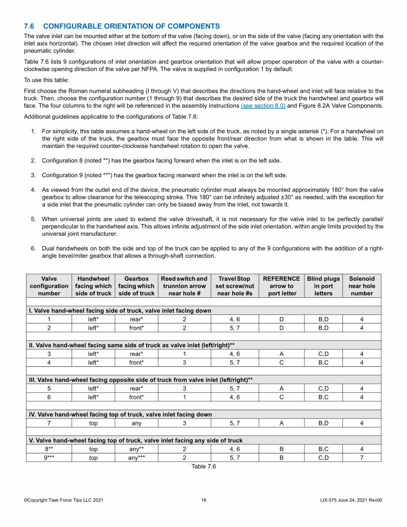
7.6 CONFIGURABLE ORIENTATION OF COMPONENTSThe valve inlet can be mounted either at the bottom of the valve (facing down), or on the side of the valve (facing any orientation with theinlet axis horizontal). The chosen inlet direction will affect the required orientation of the valve gearbox and the required location of thepneumatic cylinder.
Table 7.6 lists 9 configurations of inlet orientation and gearbox orientation that will allow proper operation of the valve with a counter-clockwise opening direction of the valve per NFPA. The valve is supplied in configuration 1 by default.
To use this table:
First choose the Roman numeral subheading (I through V) that describes the directions the hand-wheel and inlet will face relative to thetruck. Then, choose the configuration number (1 through 9) that describes the desired side of the truck the handwheel and gearbox willface. The four columns to the right will be referenced in the assembly instructions (see section 8.0) and Figure 8.2A Valve Components.
Additional guidelines applicable to the configurations of Table 7.6:
1. For simplicity, this table assumes a hand-wheel on the left side of the truck, as noted by a single asterisk (*). For a handwheel onthe right side of the truck, the gearbox must face the opposite front/rear direction from what is shown in the table. This willmaintain the required counter-clockwise handwheel rotation to open the valve.
2. Configuration 8 (noted **) has the gearbox facing forward when the inlet is on the left side.
3. Configuration 9 (noted ***) has the gearbox facing rearward when the inlet is on the left side.
4. As viewed from the outlet end of the device, the pneumatic cylinder must always be mounted approximately 180° from the valvegearbox to allow clearance for the telescoping stroke. This 180° can be infinitely adjusted ±30° as needed, with the exception fora side inlet that the pneumatic cylinder can only be biased away from the inlet, not towards it.
5. When universal joints are used to extend the valve driveshaft, it is not necessary for the valve inlet to be perfectly parallel/perpendicular to the handwheel axis. This allows infinite adjustment of the side inlet orientation, within angle limits provided by theuniversal joint manufacturer.
6. Dual handwheels on both the side and top of the truck can be applied to any of the 9 configurations with the addition of a right-angle bevel/miter gearbox that allows a through-shaft connection.
Table 7.6
Valve configuration
number
Handwheel facing whichside of truck
Gearboxfacing which side of truck
Reed switch and trunnion arrow
near hole #
Travel Stop set screw/nut near hole #s
REFERENCE arrow to
port letter
Blind plugsin portletters
Solenoid near hole number
I. Valve hand-wheel facing side of truck, valve inlet facing down1 left* rear* 2 4, 6 D B,D 42 left* front* 2 5, 7 D B,D 4
II. Valve hand-wheel facing same side of truck as valve inlet (left/right)**3 left* rear* 1 4, 6 A C,D 44 left* front* 3 5, 7 C B,C 4
III. Valve hand-wheel facing opposite side of truck from valve inlet (left/right)**5 left* rear* 3 5, 7 A C,D 46 left* front* 1 4, 6 C B,C 4
IV. Valve hand-wheel facing top of truck, valve inlet facing down7 top any 3 5, 7 A B,D 4
V. Valve hand-wheel facing top of truck, valve inlet facing any side of truck8** top any** 2 4, 6 B B,C 49*** top any*** 2 5, 7 B C,D 7

©Copyright Task Force Tips LLC 2021 17 LIX-575 June 24, 2021 Rev00
8.0 INSTALLATION INSTRUCTIONS8.1 WATERWAY INSTALLATION
1. Install the mounting brackets according to structural requirements (see section 5.0) and (see section 6.0).2. Install the top deck, with clearance hole(s) for the telescoping waterway and reed switch wiring per Figure 7.4.3. Loosen the set screw on the deck plate of the telescoping waterway. This will allow the plate to rotate freely, since the correct
orientation cannot be determined until the valve is installed.4. Install the telescoping waterway through the clearance hole, keeping the reed switch wiring above the deck.5. Install the U-bolts in the mounting brackets and torque the nuts per Section 6.0, which varies by bracket type.
8.2 VALVE CONFIGURATION
Figure 8.2A
Figure 8.2B
4X GEARBOXMOUNTINGSCREWS RETAINING RING
SPROCKET
SOLENOID BRACKET
REED SWITCH
INLET ADAPTER(ALWAYS INSTALLEDIN PORT 'A')
2X BLINDPLUGS
REFERENCE ARROWPOINTS TOWARDSPORT LETTER
PORT LETTERS(A THRU D)
4X PLUG SCREWS2X TRAVEL STOP SCREWS
TRUNNION ARROW
SCREW HOLENUMBERS(1 THRU 7)
GEARBOX FEMALE THREADS OF VALVE;TO TELESCOPING WATERWAY
RETAININGRING
SPROCKETGEARBOX
O-RING
BUSHING A
SHAFT
KEY KEY
O-RING
BUSHING B
RETAININGRING
SOLENOIDBRACKET
THRUSTWASHER
SCREWS (3X)
STANDARD SHAFT POSITION
ALTERNATE SHAFT POSITION

©Copyright Task Force Tips LLC 2021 18 LIX-575 June 24, 2021 Rev00
1. Find the desired valve configuration number in Table 7.6. With the valve on a workbench, examine it and make changes asneeded according to the following steps. Any step may be skipped if that aspect of the desired configuration already matches thephysical unit. Refer to Figure 8.2A to identify the components of the valve and gearbox.
2. Find the number listed under “REED SWITCH” in the desired row of the table. Configuration # _____. If this does not match thereed switch location on the gearbox:
A. Using a 7/16” wrench, rotate the driveshaft until the trunnion arrow points towards the number 2 position.
B. Change the screw location using a 13 mm wrench for the reed switch nut and a 6 mm hex driver for the 2 plug screws. Thenuts are permanently adhered to the reed switch, so it is not necessary to adjust the switch.
C. Apply blue Loctite sparingly to the reed switch and 2 plug screws. Install in locations per Table 7.6 and torque these threeitems to 110 in-lb.
3. Find the numbers listed under “TRAVEL STOP...” in the desired row of the table. Configuration # _____. If these numbers do notmatch the locations of set screws with nuts on sides of the gearbox:
A. Using a 7/16” wrench, rotate the driveshaft until the trunnion arrow points towards the number listed under “Reed switch andtrunnion arrow…”.
B. Referring to Figure 8.2B, remove retaining ring, sprocket, thrust washer and key. Avoid overstretching the retaining ring.
C. Change the screw locations using a 13 mm wrench for the nuts and a 6 mm hex driver for the 2 plug screws. The nuts arepermanently adhered to the set screws, so it is not necessary to adjust the screws. Apply blue Loctite sparingly to all screwsand torque to 110 in-lb.
D. Reinstall the sprocket and thrust washer over the shaft and key, then install retaining ring.4. Find the letter listed under “REFERENCE ARROW...” in the desired row of the table. Configuration # _____. If this letter does not
match the letter embossed on the valve body port nearest the REFERENCE arrow on the gearbox:
A. Using a 7/16” wrench, rotate the driveshaft until the trunnion arrow points towards the number listed under “Reed switch andtrunnion arrow…”.
B. Remove the four gearbox mounting screws using a 5/16” hex driver, then rotate the gearbox until the REFERENCE ARROWpoints towards the letter from the table. If resistance is encountered, rotate the opposite direction instead to avoid valve seatfriction. Relocate the gearbox by rotating the gearbox only, do not remove and reorient the gearbox.
C. Apply blue Loctite sparingly to the four screws, then reinstall them and torque to 200 in-lb.5. Find the letters listed under “BLIND PLUGS...” in the desired row of the table. Configuration # _____. If these letters do not
match the current port locations of the blind plugs:
A. Verify bore and thread of the unused port are clean and dry. Clean with acetone if needed.
B. Using a 1/8” hex driver, remove set screw from cross-holes of port that does not match.
C. Using a ½” square drive socket wrench (no socket installed), remove the blind plug and install it in the desired port until itbottoms out snugly.
D. Apply blue Loctite sparingly to the set screw. Install in port cross-hole and torque to 56 in-lb.6. Note - this step is rarely needed. Find the number listed under “SOLENOID...” in the desired row of the table. Configuration #
_____. If this does not match the solenoid location on the gearbox:
A. Referring to Figure 8.2B, remove retaining ring, sprocket, thrust washer and key. Avoid overstretching the retaining ring.
B. Using 6 mm hex driver, remove 3 screws from solenoid bracket, then remove bracket.
C. Remove a 2nd retaining ring, then push the shaft out of the gearbox. When resistance is encountered, twist the shaft until itcontinues to push through.
D. Remove the shaft bushings from each side of the gearbox shaft bore, then install them in the opposite sides of the gearbox.
E. Verify a key is seated firmly in the shaft midway down the length. Slide the shaft into the opposite side of the gearbox. Whenresistance is encountered, twist the shaft until it continues to push through. This may occur twice before the shaft is all theway through.
F. Reinstall retaining ring and key on shaft, immediately adjacent to the gearbox.
G. Reinstall the solenoid bracket on the same side as the key. Apply blue Loctite sparingly to 3 screws and torque to 110 in-lb.
H. Reinstall the sprocket and thrust washer over the shaft and key, then install retaining ring.
NOTICE Do not exceed 10 ft-lb / 13.5 N-m torque to the valve driveshaft (60 lb / 27 kg applied to the knob of a 4" hand wheel). Excessive torque may damage the driveshaft and render the valve inoperable.

©Copyright Task Force Tips LLC 2021 19 LIX-575 June 24, 2021 Rev00
8.3 VALVE INSTALLATION1. Below the deck, at the bottom of the telescoping waterway, verify the external O-ring groove, male threads and composite bearing
ring are clean and dry, using acetone to clean if needed. Apply silicone grease (Moly-Kote 112) to the O-ring groove and threadsonly. Install size 242 O-ring in the groove, then apply silicone grease over it.
2. Verify threaded port of valve body is clean with a thin layer of silicone grease applied to the bore and female threads. Install thevalve body onto the waterway threads until it bottoms out snugly. Apply blue Loctite sparingly to the set screw. Install in portcross-hole and torque to 56 in-lb.
3. Loosen the nuts slightly on the U-bolts of the upper and lower mounting clamps, then rotate the valve to the desired orientation.Tighten and torque the nuts per Section 6.0, which varies by bracket type.
Figure 8.3
8.4 PNEUMATIC CYLINDER INSTALLATION1. Above the deck, rotate the deck plate to an orientation that aligns with the hole in the deck and will allow the pneumatic cylinder to
clear the valve body.
2. Apply blue Loctite sparingly to set screw and begin to install it in the deck plate. With the deck plate pressed down firmly againstthe shoulder in the outer tube, torque set screw to 56 in-lb.
3. Loosen the set screw on the upper bracket nearest the outlet of the telescoping waterway, then rotate the bracket until the tab isfacing away from the cylinder mounting hole in the deck plate.
4. Below the deck, install the pneumatic cylinder through the deck and deck plate. The cylinder must be oriented such that theplumbing falls into one of the two notches on the bottom of the deck plate. While holding the cylinder up against the deck plate,install the band clamp spacer as low as practical between the telescoping waterway and the pneumatic cylinder.
5. Above the deck, have an assistant apply blue Loctite to the cylinder threads and tighten the nut until it is snug. Torque the nut to130 ft-lb using a 1-7/8” wrench.
6. Below the deck, wrap the band clamp around the pneumatic cylinder, spacer and telescoping waterway such that the two endsare touching the telescoping waterway. Tighten the nut and torque it to 43 in-lb.
7. Above the deck, apply a linear stripe of blue Loctite along the threads of rod on the pneumatic cylinder, from the end of the rod upto the jam nut. Twist the upper bracket to align the clevis with the rod, then tighten the rod into the clevis two turns using a ½”open-end wrench.
8. Apply blue Loctite sparingly to set screw of the upper bracket and begin to install it. With the bracket lifted firmly against theshoulder of the inner tube, torque set screw to 56 in-lb.
9. Continue to tighten the rod counter-clockwise into the clevis. Stop when the upper bracket lowers to contact the outer tube, thentighten the rod counter-clockwise an additional ¼-turn.
10. With a wrench on the shaft to prevent rotation, tighten the jam nut and torque it to 40 ft-lb using a ¾” wrench.
11. Provide the directional control valve inlet with a pneumatic hose having a pressure between 80 PSI and 130 PSI.
12. Verify that the LOCK position of the manual override pin (see section 4.2) is not obstructed by the pneumatic cylinder. If it isobstructed, use 1/8" hex driver to loosen the button head screw on the cable tether bracket. Apply blue Loctite to screw and installthe tether bracket, screw and override pin on the opposite side of the waterway.
O-RINGGROOVE
MALETHREADS
COMPOSITEBEARING
FEMALE THREADS BORE SET SCREW

©Copyright Task Force Tips LLC 2021 20 LIX-575 June 24, 2021 Rev00
8.5 ELECTRICAL INSTALLATION
The power supply for the Extend-A-Gun VP will need to be connected to a protected circuit from the truck power distribution center.Good mechanical connections on the wires are absolutely necessary and should be checked periodically.
• Poor electrical connections are a fire hazard and can cause intermittent operation or power loss to the Extend-A-Gun VP.• Be careful to route cables in a protected area away from high heat sources.• Always use grommets whenever wires pass through holes to prevent damage.• Secure cables with plastic wire ties or cable clamps to relieve stress on the cables.
1. Install a two-position switch in the pump panel in the vertical orientation, labeled “Deck Monitor UP” and “Deck Monitor DOWN”.Wire the switch to the device circuitry (refer to wiring diagram (see section 8.5.1).
2. To install the indicator light (supplied), drill a ½” diameter hole in the dashboard. Leave enough room for a 1-13/16” diameter labelaround the light, or a 2” wide x 1-1/2” high label next to the light. Apply one of the two warning labels (supplied) and push thepanel light through the hole in the dashboard.
3. There are three magnetic switches on the device; two are sensors for the up and down positions, and the other is to determine ifthe valve is closed. All magnetic switches ternimate in Deutsch® connectors with labels. Refer to the wiring diagram for properinstallation.
4. There is also an electrically actuated pneumatic directional control valve that raises and lowers the device via the pneumaticcylinder. The cylinder UP and DOWN electrical connections are both terminated in Deutsch connectors with labels. Refer to thewiring diagram for proper installation.
5. A safety interlock solenoid is installed on the gearbox. The safety interlock solenoid terminates in a Deutsch connector with label.Refer to the wiring diagram for proper installation.
6. Three relays are provided to complete the electrical assembly. Refer to the wiring diagram to complete and verify the devicewiring.
7. A set of warning labels is provided. Attach the warning labels in the following areas:
Figure 8.5
WARNING Injury from electrocution or damage to equipment can occur when working around live circuits. To reduce the risk of injury or damage to equipment, always disconnect power before installing or servicing electrical components.
When Light is ON, Deck Monitor is
Lower BeforeMoving Vehicle.
EXTENDED.
XG
L020
XG
L020
WARNINGXGL025XGL025
WARNING
When Light is ON,Deck Monitor isEXTENDED.Lower BeforeMoving Vehicle.
Attach the warning label (XGL020) next to the indicator light or warning label (XGL025) around the indicator light
on the truck dashboard.
Do Not Open Water ValveUntil Extend-A-Gun is Fully
EXTENDED.Damage Will Occur.
XGL040
WARNING
Attach the warning label (XGL040) near the valve control hand wheel.

©Copyright Task Force Tips LLC 2021 21 LIX-575 June 24, 2021 Rev00
8.5.1 WIRING DIAGRAM
Figure 8.5.1
8.5.2 PLUG REFERENCE
Figure 8.5.2

©Copyright Task Force Tips LLC 2021 22 LIX-575 June 24, 2021 Rev00
8.6 PNEUMATIC CALIBRATION
1. Raise the waterway by pressing the built in switch on theupper valve (A).
2. Measure the amount of time it takes the waterway to reachthe fully extended position.
3. If the duration is not about 5 seconds, adjust the timing.A. Loosen the Jam Nut on the upper flow control (B) to
adjust the timing.B. Turn flow control knob clockwise for longer duration or
counter-clockwise for shorter duration.C. After adjusting, tighten the jam nut until snug.
4. Lower the device by pressing the built in switch on thelower valve (C).
5. Measure the amount of time it takes the waterway to reachthe fully retracted position.
6. If the duration is not about 10 seconds, adjust the timing.A. Loosen the Jam Nut on the lower flow control (D) to
adjust the timing.B. Turn flow control knob clockwise for longer duration or
counter-clockwise for shorter duration.C. After adjusting, tighten the jam nut until snug.
8.6.1 TESTING THE INSTALLATIONTo ensure proper operation of the controls and related safety devices, after complete installation, perform the following actions in order.
NOTICED
Damage to equipment may occur when operated with low clearance. Always ensure there is adequate clearance before attempting to raise the waterway.
Begin with the valve in the CLOSED position and the telescoping waterway fully RETRACTED. The system must be powered up with the two-position switch on the pump panel in the DOWN position.
ACTION EXPECTED RESULT 1. Verify INDICATOR LIGHT in the cab Powered OFF (dark) 2. Open the VALVE using the manual hand wheel VALVE will not open 3. Raise the WATERWAY using the TWO-POSITION SWITCH WATERWAY fully raised in 5 seconds 4. Verify INDICATOR LIGHT in the cab Powered ON (illuminated) 5. Open the VALVE using the manual hand wheel VALVE opens smoothly 6. Retract the WATERWAY using the TWO-POSITION SWITCH WATERWAY will not move 7. Close the VALVE using the manual hand wheel VALVE closes smoothly 8. Retract the WATERWAY using the TWO-POSITION SWITCH WATERWAY fully retracted in 10 seconds 9. Verify INDICATOR LIGHT in the cab Powered OFF (dark)10. Move the VALVE position VALVE moves slightly until the lock is engaged
If an unexpected result occurs, do not use the Extend-A-Gun VP. Verify proper wiring and/or contact TFT Customer Service for assistance.
A
B
C
D
Figure 8.6

©Copyright Task Force Tips LLC 2021 23 LIX-575 June 24, 2021 Rev00
9.0 MOUNTING THE MONITORA Task Force Tips Crossfire® monitor may be mounted in one of two ways. We recommend that it be mounted directly on Extend- A-Gunmodel XGC38VL-XL, which has an integral Crossfire base built in. Alternatively, it can be mounted on Extend-A-Gun modelXGC38VL-PL using Task Force Tips part XFF-APL Truck Mount Base, which fits only the Task Force Tips Crossfire.
A Task Force Tips Radius® monitor may be mounted directly to an Extend-A-Gun with a -PL outlet.
A Task Force Tips monitor with an –RL inlet may be mounted directly to an Extend-A-Gun with a –RL outlet.
Any monitor with a 3” NPTF inlet may be mounted directly to an Extend-A-Gun with a –PL outlet.
Any monitor with 3” 4-Bolt ANSI flange inlet may be mounted to an Extend-A-Gun with a –PL outlet with the addition of an XFF-CPLCompanion Flange Kit.
9.1 TWO PIECE CLAMP ROTATIONAL LOCK INSTALLATION FOR -RL OUTLETSTask Force Tips monitors with -RL inlet are attached to the Extend-A-Gun VP by a threaded joint with an O-ring seal. The joint betweenthe Extend-A-Gun VP and monitor is locked rotationally by a two piece clamp rotational lock.
WARNING Injury or damage can occur from an inadequately supported monitor. The mounting must be capable of supporting the nozzle reaction force which can be as high as 950 lbs (430 kg).
VSA-125
VSA-125
Y4437
VW360x200-04
Y4435
VT10-32SH1.2Apply VSA-125 blue Loctite to threads on bothCylinder Nuts.
MONITOR BASE CLAMP
WASHER
SOCKET HEAD SCREW10-32 X 1-1/4 LONG
CYLINDER NUT
BLUE LOCTITE
BLUE LOCTITE
STEP 1
STEP 2
Align grooves in heads of Cylinder Nuts with topsides of Clamps.
Slide Screws through Washers and Clamps.
Loosely thread Screws into Cylinder Nuts.
TOP SIDE OF CLAMP
CYLINDER NUTHEAD GROOVE
©Copyright Task Force Tips LLC 2021 24 LIX-575 June 24, 2021 Rev00
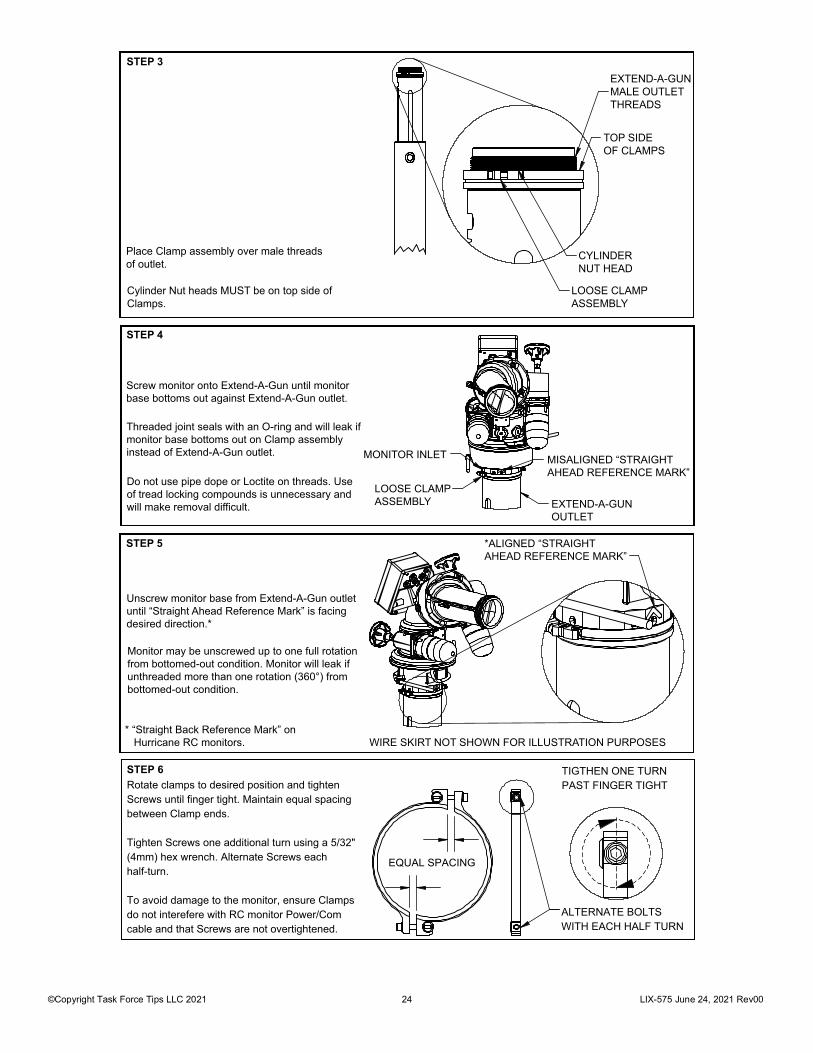
STEP 3
Place Clamp assembly over male threads of outlet.
Cylinder Nut heads MUST be on top side ofClamps.
EXTEND-A-GUNMALE OUTLETTHREADS
TOP SIDEOF CLAMPS
CYLINDERNUT HEAD
LOOSE CLAMPASSEMBLY
STEP 4
Screw monitor onto Extend-A-Gun until monitorbase bottoms out against Extend-A-Gun outlet.
Threaded joint seals with an O-ring and will leak ifmonitor base bottoms out on Clamp assemblyinstead of Extend-A-Gun outlet.
Do not use pipe dope or Loctite on threads. Useof tread locking compounds is unnecessary andwill make removal difficult.
MONITOR INLET
LOOSE CLAMPASSEMBLY
MISALIGNED “STRAIGHT AHEAD REFERENCE MARK”
EXTEND-A-GUNOUTLET
STEP 5
Unscrew monitor base from Extend-A-Gun outletuntil “Straight Ahead Reference Mark” is facingdesired direction.*
Monitor may be unscrewed up to one full rotationfrom bottomed-out condition. Monitor will leak ifunthreaded more than one rotation (360°) frombottomed-out condition.
* “Straight Back Reference Mark” on Hurricane RC monitors.
*ALIGNED “STRAIGHTAHEAD REFERENCE MARK”
WIRE SKIRT NOT SHOWN FOR ILLUSTRATION PURPOSES
EQUAL SPACING
ALTERNATE BOLTSWITH EACH HALF TURN
TIGTHEN ONE TURNPAST FINGER TIGHTRotate clamps to desired position and tighten
Screws until finger tight. Maintain equal spacing between Clamp ends.
Tighten Screws one additional turn using a 5/32" (4mm) hex wrench. Alternate Screws each half-turn.
To avoid damage to the monitor, ensure Clamps do not interefere with RC monitor Power/Com cable and that Screws are not overtightened.
STEP 6

©Copyright Task Force Tips LLC 2021 25 LIX-575 June 24, 2021 Rev00
10.0 USE OF DRAINThe Extend-A-Gun comes with (3) ¾” NPTholes on the valve inlet. The holes aredesigned to be used as a drain, or plugged if adrain is used elsewhere. A drain must beemployed to remove excess water from thesystem. This prevents freezing and allows theunit to be parked.
Always use the lowest drain port per the valveconfiguration:
- When the valve inlet is configured on thebottom, the 3/4”NPT port on the valve bodyshown in DETAIL A is the lowest drain port.
- When the valve inlet is configured on theside, use a 3/4"NPT port in one of the 2 blindplugs (as shown in Detail B). The port in theblind plug on the bottom of the valve is thelowest drain port.
11.0 WARRANTYTask Force Tips LLC, 3701 Innovation Way, Valparaiso, Indiana 46383-9327 USA (“TFT”) warrants to the original purchaser of itsproducts (“equipment”), and to anyone to whom it is transferred, that the equipment shall be free from defects in material andworkmanship during the five (5) year period from the date of purchase. TFT’s obligation under this warranty is specifically limited toreplacing or repairing the equipment (or its parts) which are shown by TFT’s examination to be in a defective condition attributable toTFT. To qualify for this limited warranty, the claimant must return the equipment to TFT, at 3701 Innovation Way, Valparaiso, Indiana46383-9327 USA, within a reasonable time after discovery of the defect. TFT will examine the equipment. If TFT determines that there isa defect attributable to it, TFT will correct the problem within a reasonable time. If the equipment is covered by this limited warranty, TFTwill assume the expenses of repair.
If any defect attributable to TFT under this limited warranty cannot be reasonably cured by repair or replacement, TFT may elect torefund the purchase price of the equipment, less reasonable depreciation, in complete discharge of its obligations under this limitedwarranty. If TFT makes this election, claimant shall return the equipment to TFT free and clear of any liens and encumbrances.
This is a limited warranty. The original purchaser of the equipment, any person to whom it is transferred, and any person who is anintended or unintended beneficiary of the equipment, shall not be entitled to recover from TFT any consequential or incidental damagesfor injury to person and/or property resulting from any defective equipment manufactured or assembled by TFT.
It is agreed and understood that the price stated for the equipment is in part consideration for limiting TFT’s liability. Some states do notallow the exclusion or limitation of incidental or consequential damages, so the above may not apply to you.
TFT shall have no obligation under this limited warranty if the equipment is, or has been, misused or neglected (including failure toprovide reasonable maintenance) or if there have been accidents to the equipment or if it has been repaired or altered by someone else.
THIS IS A LIMITED EXPRESS WARRANTY ONLY. TFT EXPRESSLY DISCLAIMS WITH RESPECT TO THE EQUIPMENT ALLIMPLIED WARRANTIES OF MERCHANTABILITY AND ALL IMPLIED WARRANTIES OF FITNESS FOR A PARTICULAR PURPOSE.THERE IS NO WARRANTY OF ANY NATURE MADE BY TFT BEYOND THAT STATED IN THIS DOCUMENT.
This limited warranty gives you specific legal rights, and you may also have other rights which vary from state to state.
WARNING Equipment may be damaged if frozen while containing significant amounts of water. Such damage may be difficult to detect visually. Subsequent pressurization can lead to injury or death. Any time the equipment is subject to possible damage due to freezing, it must be tested and approved for use by qualified personnel before being considered safe for use.
Figure 10.0
DETAIL A
3/4" NPT
2XDETAIL B
3/4" NPT

©Copyright Task Force Tips LLC 2021 26 LIX-575 June 24, 2021 Rev00
12.0 MAINTENANCE The Extend-A-Gun VP requires little maintenance. The Extend-A-Gun VP should be kept clean and free of dirt. All controls should bechecked for freedom of movement and proper operation before each use. Any inoperable or damaged parts should be repaired orreplaced immediately. Consult factory for recommended service procedure.
12.1 LUBRICATIONThe Extend-A-Gun VP is permanently lubricated on the cup seal. If lubricant has been removed during service, apply a thin film of WhiteLithium Grease on seal surfaces.
12.2 VALVE SEAT REPLACEMENTThe valve seat may be replaced in the field if it becomes a source of leakage due to harsh environmental conditions or excessive age. Ahook type spanner wrench sized to fit a 4.8” diameter may be used to remove and install the valve seat.
Follow the steps below to replace the valve seat:
1. Toggle the switch to the UP position to raise the telescoping waterway.
2. Fully open the valve to ensure pressure has been relieved and to protect the half ball while the valve seat is being removed.
3. Drain the pipe immediately upstream of the valve, then loosen or remove the pipe to allow a minimum of 2” of working clearanceadjacent to the Victaulic inlet adapter. This inlet adapter shown in Figure 3.3 (bottom inlet configuration) and Figure 8.2A (sideinlet configuration) also serves as the valve seat retainer.
4. Near the “A” port marking, on the opposite side of the valve body from the gearbox, loosen the set screw by 4 full turns.
5. Using hook type spanner wrench, remove the inlet adapter.
6. Using pliers, pull old valve seat out of groove in valve body.
7. Close the valve and clean all sealing surfaces of the half ball, valve body and inlet adapter. Also clean all debris from threads ofvalve body and inlet adapter using acetone. Verify all sealing surfaces are smooth and intact. If significant damage is visible,consult Task Force Tips Service Department.
8. Apply light coat of silicone based grease such as Moly-Kote 112 to all sealing surfaces and threads of half ball, valve body, andinlet adapter. Open valve so half ball is out of the way.
9. Install new valve seat into groove in valve body with wider side facing the half ball. Apply silicone grease to the bore of the valveseat.
10. Install inlet adapter until it is snug against the valve seat, then adjust it so the nearest wrenching notch in the O.D. is aligned withthe set screw hole.
11. Apply blue Loctite to set screw and torque to 56 in-lb.
12. Reassemble the upstream plumbing and test the valve. If leaks are observed through the valve seat, try tightening the inletadapter until it has advanced two additional notches with respect to the set screw hole (60° rotation).

©Copyright Task Force Tips LLC 2021 27 LIX-575 June 24, 2021 Rev00
13.0 TROUBLE SHOOTING
Table 13.0
SYMPTOM POSSIBLE CAUSE REMEDYFlow through monitor with valve in closed position
1. Debris or damage to the valve seat or half ball 1. Clean out debris or replace damaged parts.
Leaks on exterior 2. Debris or damage in an O-ring seal area 2. Clean out debris or replace damaged parts.
Valve will not open with telescoping waterway raised
3. Poor connection from UP reed switch
4. Poor connection to valve lock solenoid
3. Per Figure 8.5.1, verify continuity from Relay 3 terminal 85 to ground.
4. Verify 9 to 15 volts from Relay 3 terminal 87 to ground.
Does not raise 5. Mechanical binding
6. Improper pressure balance at pneumatic cylinder.
7. Poor UP electrical connection
5. With switch in DOWN position and power off, manually lift/lower telescoping waterway several times per Section 10.3. Turn power on and switch UP/DOWN several times to verify pneumatic cylinder rod moves smoothly. Reassemble.
6. Per Section , press the built-in switch on the upper solenoid valve (A) and verify less than 10 seconds to raise. If not, verify 80+ psi, then follow the pneumatic calibration instructions.
7. Per Figure 8.5.1, with switch in UP position, verify continuity from terminal 85 to ground, then verify 10+ volts from ground to the following 3 terminals on Relay 1: 30, 86, and 87 (NO). Next, verify 9 to 15 volts at UP solenoid connection of direction control valve by removing the Phillips head screw from the connector and sliding it off the control valve.
Does not lower 8. Valve is OPEN
9. Improper pressure balance at pneumatic cylinder.
10. Poor connection from VALVE CLOSED reed switch
11. Poor DOWN electrical connection
8. Close the valve before lowering the waterway.
9. Per Section , press the built-in switch on the upper solenoid valve (B) and verify less than 10 seconds to lower. If not, then verify 80+ psi then follow the pneumatic calibration instructions.
10. Per Figure 8.5.1, verify continuity through the 2 pins of the Reed Switch 1 Deutsch plug.
11. Per Figure 8.5.1, with switch in DOWN position, verify no continuity from terminal 85 to ground, then verify 9 to 15 volts from ground to the following 3 terminals on Relay 1: 30, 86, and 87a (NC). Next, verify 9 to 15 volts at DOWN solenoid connection of direction control valve by removing the Phillips head screw from the connector and sliding it off the control valve.

©Copyright Task Force Tips LLC 2021 28 LIX-575 June 24, 2021 Rev00
TASK FORCE TIPS LLCMADE IN USA · tft.com
3701 Innovation Way, Valparaiso, IN 46383-9327 USA800-348-2686 · 219-462-6161 · Fax 219-464-7155
13.1 REPAIRFactory service is available with repair time seldom exceeding one day in our facility. Factory serviced equipment is repaired byexperienced technicians, wet tested to original specifications, and promptly returned. Any returns should include a note as to the natureof the problem and whom to reach in case of questions.
Repair parts and service procedures are available for those wishing to perform their own repairs. Task Force Tips assumes no liability fordamage to equipment or injury to personnel that is a result of user service. Contact the factory or visit the web site at tft.com for partslists, exploded views, test procedures and troubleshooting guides.
Performance tests shall be conducted on the equipment after a repair, or anytime a problem is reported to verify operation in accordancewith TFT test procedures. Consult factory for the procedure that corresponds to the model and serial number of the equipment. Anyequipment which fails the related test criteria should be removed from service immediately. Troubleshooting guides are available witheach test procedure or equipment can be returned to the factory for service and testing.
14.0 EXPLODED VIEWS AND PARTS LISTSExploded views and parts lists are available at tft.com/serial-number.
15.0 OPERATION AND INSPECTION CHECKLISTBEFORE EACH USE, the Extend-A-Gun VP must be inspected to this checklist:
1. There is no obvious damage such as missing, broken or loose parts, damaged labels, etc.2. All controls move freely and operate properly.3. The Extend-A-Gun VP operates freely without binding throughout its range of travel.4. There are no leaks when the Extend-A-Gun VP is flowing water.
BEFORE BEING PLACED BACK IN SERVICE, the Extend-A-Gun VP must be inspected to this list:1. All controls and adjustments are operational.2. There are no broken or missing parts.3. There is no damage to the Extend-A-Gun VP or attached monitor that could impair safe operation (e.g. detents, cracks, corrosion,
or other defects).4. The waterway is clear of obstructions.5. The Extend-A-Gun VP is clean and markings are legible.
WARNING Service technicians bear responsibility for ensuring use of appropriate protective clothing andequipment. The chosen protective clothing and equipment must provide protection from potentialhazards users may encounter while servicing equipment. Requirements for protective clothing andequipment are determined by the Authority Having Jurisdiction (AHJ).
CAUTION Any alterations to the product or its markings could diminish safety and constitutes a misuse of this product.
NOTICE All replacement parts must be obtained from the manufacturer to assure proper operation of the device.
WARNING Equipment failing any part of the checklist is unsafe for use and must have the problem corrected before use or being placed back into service. Operating equipment that has failed the checklist is a misuse of this equipment.