fyp12026 gesture recognition on...
TRANSCRIPT

FYP12026 GESTURE RECOGNITION ON
SMARTPHONE Final Report
Li Yin Kong 2009127643 Supervisor: Dr. Kenneth Wong

1
Table of Contents 1. Abstract ......................................................................................................................................................... 2
2. Introduction .................................................................................................................................................. 2
3. Use Case Scenarios ........................................................................................................................................ 3
4. Assumptions .................................................................................................................................................. 4
5. Development Platform .................................................................................................................................. 5
6. Gesture Recognition System ......................................................................................................................... 6
6.1. Overview .............................................................................................................................................. 6
6.2. Skin Detection ...................................................................................................................................... 6
6.2.1. YCrCb Color Space for Skin Modelling .............................................................................................. 6
6.2.2. Skin Modelling .................................................................................................................................. 8
6.2.3. Offline Training ................................................................................................................................ 9
6.2.4. Back Projection .............................................................................................................................. 11
6.2.5. Determining the Threshold ............................................................................................................ 12
6.2.6. Improving the Detection ................................................................................................................ 14
6.3. Blob Tracking ...................................................................................................................................... 15
6.3.1. Blob Modelling ............................................................................................................................... 15
6.3.2. Kalman Filter .................................................................................................................................. 17
6.3.3. Blob Matching ................................................................................................................................ 18
6.4. Gesture Recognition ........................................................................................................................... 18
6.4.1. Finger Detection ............................................................................................................................. 18
6.4.2. Gesture Recognition ...................................................................................................................... 21
6.4.3. Gesture Definition .......................................................................................................................... 22
7. Application Architecture ............................................................................................................................. 24
7.1. Native C++ Part................................................................................................................................... 24
1.1. Java Part ............................................................................................................................................. 25
8. Demo Applications ...................................................................................................................................... 26
8.1. Video Player ....................................................................................................................................... 26
8.2. Game .................................................................................................................................................. 27
9. Timeline and Milestones ............................................................................................................................. 27
10. Future Work ........................................................................................................................................... 28
10.1. Adaptive Skin Detection ..................................................................................................................... 28
10.2. Tracking with Momentary Occlusion ................................................................................................. 28

2
11. Conclusion .............................................................................................................................................. 29
1. Abstract
Gesture-based human computer interface is becoming increasingly popular among game developers as
this kind of interaction introduces a whole new experience to computer users. For instance, Microsoft
invented Kinect for Xbox to enhance the experience of gaming. It allows video game players to play
games with their body gesture and without any game controllers by processing the depth information
collected from its sensors. Questions aroused as to whether it is possible to use the cameras on
handheld devices, like smartphones and tablets, to create a new way of interacting with the devices. In
this project, we try to create a real-time hand gesture recognition interface with which users can control
their phones without having to use the touchscreen given the input frames captured using the camera
on the phone. The interface is based on visual cues including color and the contour of the hands.
2. Introduction
In this new era of mobile computing, the smartphone adoption rate is ever increasing. According to a
survey conducted by Flurry, the growth rate of active smart devices in China between January 2012 and
January 2013 was a staggering figure, 209%1.To smartphone makers, this is a huge market and they
must look for some way to differentiate themselves from other.
At the same time, as the Moore’s Law suggested, the chip performance doubles approximately every
two years. Like desktop PCs, Smartphones are powered by multi-core CPUs. The ones that belong to the
high-end market are already equipped quad-core CPUs, and many of them also come with discrete
multi-core GPUs. The processors on these smart devices are now capable of doing heavy computational
1 (Farago, 2013) China Knocks Off U.S. to Become World's Top Smart Device Market. Retrieved April 19, 2013, from
http://pdf.aminer.org/000/312/166/finding_facial_features_using_an_hls_colour_space.pdf

3
tasks, such as playing realistic 3D games in high definition resolution, and augmented reality. Besides,
the majority of smartphones have installed at least one camera, enabling the device to “see” what is
happening around it.
This improvement in hardware performance enables the shift to mobile computing, allowing people to
do tasks with their mobile phones instead of their PCs. In the past, Computer vision used to be bound to
desktop computers, but now with these advanced hardware, it is possible for computer vision software
to be run on smartphones.
In this project, we aim to develop a hand gesture-based interface using images captured from the front-
facing camera to control smartphones powered by Google Android with the help of an open source
computer vision library OpenCV. Third-party developers could use our interface in his own application to
deliver highly interactive applications.
3. Use Case Scenarios
Gesture-based HCI is appealing to situations in which the touchscreen is unreachable. For instance, the
user is sitting on a couch, watching a video stored on the phone and use HDMI to output the stream to a
large external monitor. Then the user would be at a far distance from the phone and any fast forward,
rewind or pause actions would require the user to walk to the phone and push the buttons on the
screen. From the perspective of a user, this is very inconvenient. However, with the new gesture
interface, the user can just keep sitting and move his hand to perform above mentioned actions.
Another possible situation is that the use of touchscreen is undesirable. For example, when the user is
watching video while having a McDonald’s meal, his hands would be greasy. He does not want to touch
the phone and make it dirty. So he could just perform a gesture to control the playback. Or in less
frequent cases, the hands may be wet. Touching the phone may cause water damage to it.

4
What’s more, this kind of HCI could improve the gaming experience on smart devices. Most games now
available on the app stores use the touchscreen and/or the readings from accelerometer as input. The
combination of controls is somehow limited. Also, touching the screen would occlude some of the visual
elements of the games, making them visible to users which directly reduce the usable landscape of the
screen. With gesture, the experience is more immersive and realistic. They can play boxing games like
they are really in a fight.
4. Assumptions
As we are developing an application for a mobile device, the computing power, although it has improved
over the years, is somehow limited. If we want complex gestures to be recognized accurately, it would
be stressful for a mobile chip to process. Also, as it is a process running in the background, it should not
take up too much system resources. Otherwise, the foreground application may not have sufficient
memory to operate, and there may be sluggishness. Therefore we try to make the interface as simple as
possible. By making some assumptions, we can simplify the whole problem.
We can assume that, in the three cases of the previous section, the camera is statically placed and is
facing the user. The background thus does not differ much from the previous frames, except moving
objects or change in lighting condition.
Another assumption is that any skin-colored or similarly-colored objects like hands or faces do not
occlude each other. As we shall describe later in this report, the detection of hands is based on color,
this assumption simplifies the cases where the hand region overlaps the face region which increase the
complexity of distinguishing which pixel belongs to which blob and tracking them afterwards.
5
5. Development Platform
Our target platform is Google Android because of its openness and support in the community. Also, the
required capital for developing our work is much cheaper when compared to Apple’s iOS. We aim to
support Android 4.0 or above as smartphones with older Android version may not have the computing
power to handle our application.
To accelerate our development process, we used the excellent open source computer vision library
named OpenCV. Its built-in modules includes image processing, object detection, machine learning, etc.
It saves us a tremendous amount of time and effort without having to implement some very basic
algorithms on our own. Many of the functions provided are parallelized by the Intel Threading Building
Blocks (TBB) library which harness the concurrent computing power of multicore processors. It is also
available for iOS and Mac systems, therefore it would be easy to port to other platforms in the future.
The version we used is the latest one, namely 2.4.5.
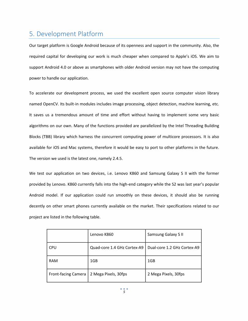
We test our application on two devices, i.e. Lenovo K860 and Samsung Galaxy S II with the former
provided by Lenovo. K860 currently falls into the high-end category while the S2 was last year’s popular
Android model. If our application could run smoothly on these devices, it should also be running
decently on other smart phones currently available on the market. Their specifications related to our
project are listed in the following table.
Lenovo K860 Samsung Galaxy S II
CPU Quad-core 1.4 GHz Cortex-A9 Dual-core 1.2 GHz Cortex-A9
RAM 1GB 1GB
Front-facing Camera 2 Mega Pixels, 30fps 2 Mega Pixels, 30fps

6
Android Version 4.0.4 4.0.4
Note that the camera resolution is the maximum resolution for taking pictures, while the size of the
frames we get for processing is much smaller due to hardware limitation.
6. Gesture Recognition System
6.1. Overview
There are three major stages of the gesture recognition, namely detection, tracking and recognition. In
detection, the major task is to segment the user’s hands from the input images. Tracking means to
follow the movement of detected blobs in a temporal sequence of images. After tracking the movement,
we can recognize the gestures performed by analysis the posture of the hands.
6.2. Skin Detection
To segment hands from input images, we use skin detection by color features. Its processing is fast
compared to template matching as it is performed on a per-pixel basis. It is also highly robust to
geometric variation of the hand gestures where template matching would fail miserably. Then the
question becomes how to model skin color.
6.2.1. YCrCb Color Space for Skin Modelling
Since the color of skin is formed by a combination of blood and the pigment melanin which appears
brown or black, the human skin color has a restricted range of hues. The difference between various
races is mainly due to the amount of melanin underneath the skin. Skin color clusters at a small area in
the color space, choosing an appropriate color space is crucial to minimize the cluster.

7
Normalized rg color space and YCrCb are two popular options that have been studied extensively. rg
chromaticity is converted from RGB by finding the portion of red and green in the original color. The
formula of conversion is given by:
As the three components must sum up to 1, the b component is insignificant and can be omitted. On the
other hand, YCrCb separates luminance component (Y) and chrominance component (Cr and Cb) from
the original image. The conversion is as follow:
Both conversions are very simple and quick as compared to other color spaces like HSV, TSL. The
following graph2 shows the density plots (histograms) of skin color of Asian, African and Caucasian in the
mentioned color spaces. The coordinate represents the color value in the corresponding color space.
Warm color represents high density (occurrence) for that color while cold color represents low density.
2 (Elgammal, Muang, & Dunxu, 2009) Skin Detection - a Short Tutorial. Retrieved April 19, 2013, from
http://pdf.aminer.org/000/312/166/finding_facial_features_using_an_hls_colour_space.pdf
8
It can be seen from the figure that the cluster in the YCrCb color space is more compact than that in rg-
space. We choose the YCrCb color space to model skin color because of its compactness. Dropping the
luminance component gives us some extent of robustness against illumination changes. It also reduces
the number of dimensions to 2.
6.2.2. Skin Modelling
To model the skin color, we tried three approaches, namely explicitly defined skin region, parametric
Gaussian Mixture Model, and nonparametric Bayes Classifier. We found that the third one is more
appropriate to our application.
The first method defines explicitly the boundaries of skin cluster in the color space. If the color vector of
a pixel satisfies such rules, it is classified as skin, or non-skin otherwise. As shown in the previous section,
the shape of the cluster in YCrCb color space resembles a rotated ellipse. So we just check if the
coordinate of the color falls within that ellipse and decide if it is skin. Although this approach is fast, the
detection rate is not satisfying and it does not give any information regarding the likelihood of a pixel
being skin.
The second method assumes that the variables, color in our case, are distributed under a mixture of
Gaussian. To model skin color, we then need to find out the kernels, and their mean, covariance, and
weight. This model is significantly harder to train and the computation is expensive as we need to
evaluate each of the Gaussians to get the probability of a color being skin. For smartphones, we do not
think that this approach is efficient enough to be run at real time.
We decided to use the third nonparametric approach without having to derive an explicit model of the
skin color. Because this method is independent to the shape of skin color distribution, but still we need
to estimate the distribution from training data.

9
The classifier we used is based on Bayes’ rule. Given the color of a pixel, the probability of it being skin
pixel , can be computed as
If the probability of a pixel is greater than a certain threshold , then we classify this pixel as skin, and
non-skin otherwise. We can obtain the values of and statistically through training. The value
of is insignificant to our analysis as this is a constant value and we can always scale the threshold
accordingly.
By using color histograms, we can compute the values of and by counting the occurrence of
that specific color divided by the total occurrence of all color in the corresponding histograms. In
other words we normalize the histograms to get
as the probability for color .
As the color depth of the images captured from the camera is 24-bit, meaning 8 bits per channel, the
total number of combination is . This means that we need a huge number of
bins for the histograms, and as each bin is essentially a 32-bit floating point number storing the count,
the memory space required is unbearable for handheld devices. To cope with this requirement, we omit
the Y component of the YCrCb color space as mentioned before and reduce the histogram size to 64 per
channel. Then the total number of bins would just be , which is much more acceptable
for smart phones.
6.2.3. Offline Training
The aforementioned training would require a huge training set to sample the skin probability. Using the
testing devices’ camera, we took a set of photos capturing the hands under different lighting conditions.
Each training image is accompanied with a ground truth binary image (mask) clearly labelling regions of

10
skin. Pixel in the mask image having value of 255 (white) is skin whereas pixel of value 0 (black) is non-
skin. An example is shown below:
To facilitate the process of creating mask images, we have developed a tool that makes use of the
principle of flood filling. When the user click on the image, the point under the cursor is used as the seed
point for flood filling. In some cases where the hand may appear to be the in similar color as the
background, the user can slide the track bar and adjust the upper and lower threshold for color
difference. Then skin regions in the image can be segmented quickly even for images with complex hand
contour. After segmentation, the tool will output a binary image to be stored along with the original
image. The follow graph shows the user interface of the tool, the left window shows the original image
along with flood filled pixels while the window on the right shows the mask.
11
After we obtain the training data and the binary masks which represent the ground truth or response
data, we can calculate the two 2D histograms, namely skin-color histogram and all-color histogram
which stand for the probabilities and respectively. Out of the two dimensions of the
histograms, one corresponds to the Cr value and the other to the Cb value of the pixel. Then the values
of Cr and Cb become the coordinate of the bin that this pixel belongs to.
We first convert the image in RGB format to YCrCb format. Then we scan through the whole image pixel
by pixel, and increment the count of the bin corresponding to the color of that pixel in the all-color
histogram. If the value of the pixel at the same coordinate in the binary mask is non-zero, then we also
increment the count of that color in the skin-color histogram. What follows is the normalization of the
histograms such that the sum of probabilities in each histogram is 1. Finally, the posterior probability
is computed by dividing the count of each of the bins in the skin-color histogram to that of the
same coordinate in the all-color histogram to get another histogram. This final histogram is often
referred to as the Skin Probability Map (SPM) that acts as a lookup table and assigns a probability to
each point in the quantized color space.
6.2.4. Back Projection
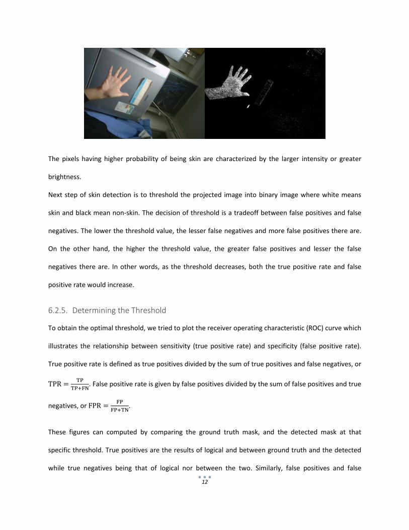
With the SPM, we can now assign the probabilities to the pixels of the input image. This process is
known as back projection. Instead of incrementing the counters of the bins, we read the values to obtain
a single channel image in which pixels of higher value is more likely to be skin. The following graph
shows the original image and the projected grayscale image:
12
The pixels having higher probability of being skin are characterized by the larger intensity or greater
brightness.
Next step of skin detection is to threshold the projected image into binary image where white means
skin and black mean non-skin. The decision of threshold is a tradeoff between false positives and false
negatives. The lower the threshold value, the lesser false negatives and more false positives there are.
On the other hand, the higher the threshold value, the greater false positives and lesser the false
negatives there are. In other words, as the threshold decreases, both the true positive rate and false
positive rate would increase.
6.2.5. Determining the Threshold
To obtain the optimal threshold, we tried to plot the receiver operating characteristic (ROC) curve which
illustrates the relationship between sensitivity (true positive rate) and specificity (false positive rate).
True positive rate is defined as true positives divided by the sum of true positives and false negatives, or
. False positive rate is given by false positives divided by the sum of false positives and true
negatives, or
.
These figures can computed by comparing the ground truth mask, and the detected mask at that
specific threshold. True positives are the results of logical and between ground truth and the detected
while true negatives being that of logical nor between the two. Similarly, false positives and false

13
negatives are computed using logical operators. Using greater-than operators on the detected mask and
ground truth mask gives us the false positives, and less-than operator gives false negatives.
After calculating these numbers at different thresholds, we can plot the ROC as follow.
The graph confirmed our belief that there exists a trade-off between false positives and false negatives.
Then we can assign costs to the two rates and find the threshold that minimum the total cost. After that,
thresholding gives us a binary mask of regions being very likely to be skin. As there are Gaussian noise,
some pixels outside skin regions may suddenly appear to be skin-colored. To reduce the effect of such
noise, a morphological opening operation is performed on the detected mask. Basically, it is the dilation
of the erosion of the original image. Erosion removes noise of small size and dilation tries to restore the
original contour of the connected component.
14
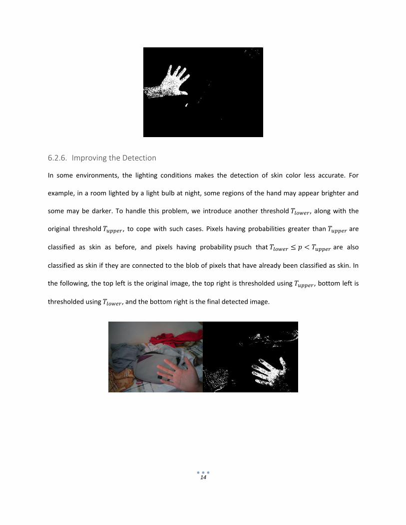
6.2.6. Improving the Detection
In some environments, the lighting conditions makes the detection of skin color less accurate. For
example, in a room lighted by a light bulb at night, some regions of the hand may appear brighter and
some may be darker. To handle this problem, we introduce another threshold , along with the
original threshold , to cope with such cases. Pixels having probabilities greater than are
classified as skin as before, and pixels having probability such that are also
classified as skin if they are connected to the blob of pixels that have already been classified as skin. In
the following, the top left is the original image, the top right is thresholded using , bottom left is
thresholded using , and the bottom right is the final detected image.

15
We can see that although this method can find a more complete skin region under slight change in light
condition, the red pants in the background is detected as skin falsely. Yet, color based skin detection still
suffers from the fundamental flaw that if a non-skin object is in skin tone, it would be wrongly classified
as skin. Then, we need extra information regarding the blob to identify hands. We will discuss this piece
of information in later section.
6.3. Blob Tracking
We then proceed to the second stage of our system. In the section, we describe the method we used to
track the detected skin pixels over sequence of frames.
6.3.1. Blob Modelling
We first run a standard connect component labelling algorithm to group skin pixels into a set of
connected components. We also find the contour of these connect components at the same time. The
contour information is useful for later stage of processing.
Each blob is modelled as a circle in our system. Although this model is naive and in reality the shape of
hands does not resemble a circle, the computation of such circles are fast. It also gives us a hint of the
size of the hands. As we do not restrict the distance between the user and the camera as long as the
hands are detected successfully, the processing of the hand gesture should be scale invariant. The radius
of the circle allows us to do gesture computation on a relative scale. For example, instead of calculating
how many pixels has the hand moved in the view of field of the camera, we compute the ratio of
16
distance that the hand travelled to the radius of it. Distance here means an approximation of Euclidean
distance instead of Manhattan distance.
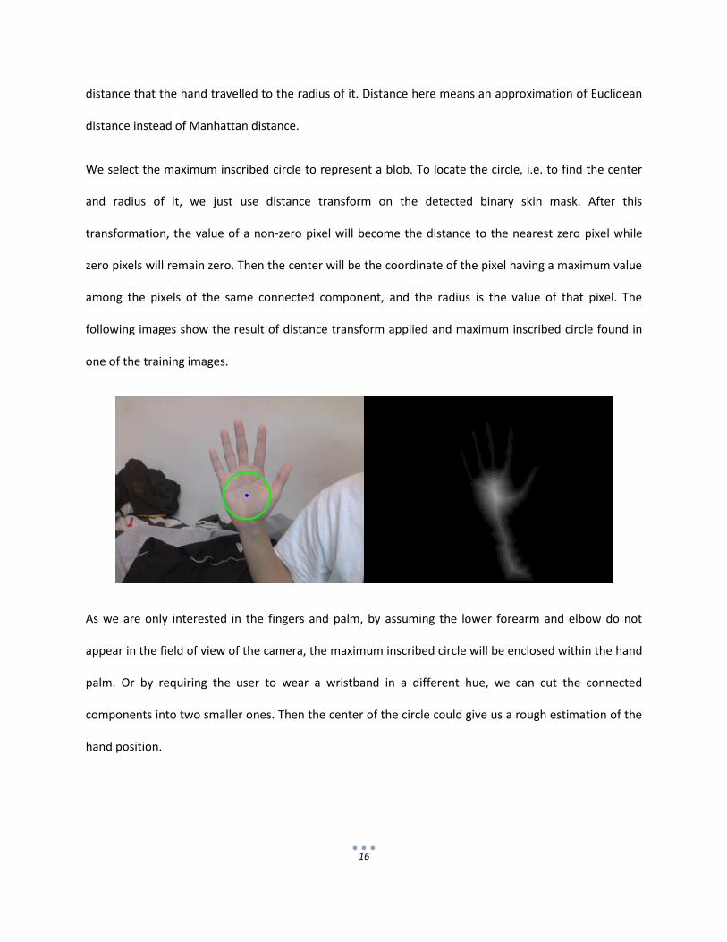
We select the maximum inscribed circle to represent a blob. To locate the circle, i.e. to find the center
and radius of it, we just use distance transform on the detected binary skin mask. After this
transformation, the value of a non-zero pixel will become the distance to the nearest zero pixel while
zero pixels will remain zero. Then the center will be the coordinate of the pixel having a maximum value
among the pixels of the same connected component, and the radius is the value of that pixel. The
following images show the result of distance transform applied and maximum inscribed circle found in
one of the training images.
As we are only interested in the fingers and palm, by assuming the lower forearm and elbow do not
appear in the field of view of the camera, the maximum inscribed circle will be enclosed within the hand
palm. Or by requiring the user to wear a wristband in a different hue, we can cut the connected
components into two smaller ones. Then the center of the circle could give us a rough estimation of the
hand position.

17
When compared to using centroid as the estimator, this approach has the advantage that when the user
closes his palm, the position would not change much. Also, the upper forearm does not have effect on
the center as it would in the case of centroid.
6.3.2. Kalman Filter
As in all other sensors, the readings would contain noises. The detected position of the hand may varies
greatly. A fluctuating hand position is highly undesirable if the interface is used as a pointing device. In
order to smooth out the readings and predict the state of the hand, we incorporated Kalman Filter into
our system.
Kalman filter estimates an optimal state statistically by assuming that both the measurement and noise
follow a Gaussian distribution. There are two main stages, and they are prediction and correction. In the
first stage, the filter estimates the true state by evolving the state of the previous time frame taking the
process noise into consideration. Then in the second stage, the measurement read from sensors along
with observation noise are used to update the state by taking a weight average of the estimated and
measured.
In our system, the state variables include the x-coordinate, y-coordinate, velocity and acceleration in
both x and y direction. Or we can simply write the relationships using equations of the laws of dynamics
as follow.
[
]
[ ]
[
]
The vector on the left hand side is the predicted state vector at time . It is estimated as the state
transition matrix multiply by the state vector at a previous time , plus the process noise .

18
6.3.3. Blob Matching
Given the predicted position in the next frame, we can track the movement of the blobs over a
sequence of images. We match the blobs using a minimum distance approach. For circles, the distance is
given by √
. Circles overlapping each other will have a negative
distance.
In the system, we keep in memory the information of each tracked blob. Before processing of a new
frame, we predict the positions of existing blobs. Then for each frame, blob detection is first applied to
locate their centers. Then for each pair of old blob and new blob, we calculate the distance between
them. After that, the distances are sorted in ascending order in a priority queue. While the queue is non-
empty, we pop the front and see if they have previously marked matched. If both of them are not
marked, we update the state of the tracked blob with the position of the new blob and marked them as
matched. Otherwise, we repeat until the queue is empty.
As the end of iteration, there may be some old blobs that are not matched. The reasons can be that the
object has moved out of the view, or it has overlapped with another object. As we assumed that the
latter would not happen, we just remove the blob from the vector of tracked blob.
Another possibility is that there is a new skin-colored object entering the view of the camera. In this case,
we push this blob to the vector and start tracking it with Kalman filter.
6.4. Gesture Recognition
6.4.1. Finger Detection
Fingers can be characterized by fingertips, the detection of fingertips leads us . As stated before, the
contour information of a blob is very useful. In particular, contours are the cues for locating the
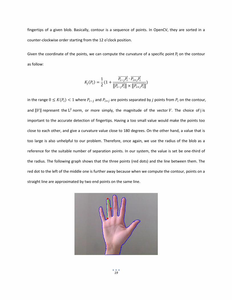
19
fingertips of a given blob. Basically, contour is a sequence of points. In OpenCV, they are sorted in a
counter-clockwise order starting from the 12 o’clock position.
Given the coordinate of the points, we can compute the curvature of a specific point on the contour
as follow:
‖ ‖ ‖ ‖
in the range where and are points separated by points from on the contour,
and ‖ ‖ represent the norm, or more simply, the magnitude of the vector . The choice of is
important to the accurate detection of fingertips. Having a too small value would make the points too
close to each other, and give a curvature value close to 180 degrees. On the other hand, a value that is
too large is also unhelpful to our problem. Therefore, once again, we use the radius of the blob as a
reference for the suitable number of separation points. In our system, the value is set be one-third of
the radius. The following graph shows that the three points (red dots) and the line between them. The
red dot to the left of the middle one is further away because when we compute the contour, points on a
straight line are approximated by two end points on the same line.

20
Observe that the curvature of points on the fingertips should be significantly greater than other points
on the contour. If the curvature of a point exceeds the threshold 0.7, then this point is a possible
candidate to represent the fingertip.
However, due to the nature of hands, the valleys between fingers also have a sharp curvature. To filter
out these valleys, we convert the two vectors and into 3D vectors by giving them a z
component of value 0 and compute the z component of the cross product. Should the value is positive,
it is a peak or a valley otherwise.
Still, there could many points on a fingertip that satisfy these two constraints. We choose the one whose
distance to the center of the maximum inscribed circle is a local maximum. Using again as the
minimum number of separation points between fingertip points, we can avoid having two points on the
same fingertips. This means that for each candidate, we check whether the difference between the
indices is smaller than . If not, we treat this point as a new candidate. Otherwise, we compare their
distances to center, the one with the smaller value will replace the original point as a candidate.
In addition, sometimes two points on the forearm on each side may be wrongly classified as fingertips
due to the fact the image cannot fully contain the skin region. Or in some cases where the user is
wearing a long sleeve apparel, the two end points on the wrist may also cause error. To resolve this
issue, we impose one more constraint that the y-coordinate of the candidate cannot be greater than of
the center by the radius (with the origin of the x-y plane being the top-left corner).
21
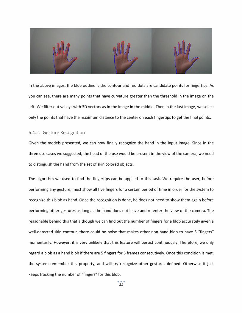
In the above images, the blue outline is the contour and red dots are candidate points for fingertips. As
you can see, there are many points that have curvature greater than the threshold in the image on the
left. We filter out valleys with 3D vectors as in the image in the middle. Then in the last image, we select
only the points that have the maximum distance to the center on each fingertips to get the final points.
6.4.2. Gesture Recognition
Given the models presented, we can now finally recognize the hand in the input image. Since in the
three use cases we suggested, the head of the use would be present in the view of the camera, we need
to distinguish the hand from the set of skin colored objects.
The algorithm we used to find the fingertips can be applied to this task. We require the user, before
performing any gesture, must show all five fingers for a certain period of time in order for the system to
recognize this blob as hand. Once the recognition is done, he does not need to show them again before
performing other gestures as long as the hand does not leave and re-enter the view of the camera. The
reasonable behind this that although we can find out the number of fingers for a blob accurately given a
well-detected skin contour, there could be noise that makes other non-hand blob to have 5 “fingers”
momentarily. However, it is very unlikely that this feature will persist continuously. Therefore, we only
regard a blob as a hand blob if there are 5 fingers for 5 frames consecutively. Once this condition is met,
the system remember this property, and will try recognize other gestures defined. Otherwise it just
keeps tracking the number of “fingers” for this blob.
22
6.4.3. Gesture Definition
With information of the position, velocity, and the number of fingers, we can then define some
comprehensive and intuitive gestures to be recognized by the system. There are two types of gestures
defined, one of them being state change gestures and the other are just gestures of being in certain
states.
As stated before, there is an engagement event when the user shows an open palm for a short period of
time for the first time. This event is meaningful for developers as it entails the start of gesture, and they
can notify the user with some user interface elements that he can start doing gestures.
Another gesture we defined is the pointing gesture. It is posture of the hand extending two fingers only
and belongs to the second type of gesture. The position of the hand will be passed as an additional
argument for developers to analyze the trajectory of the hand.
If the user close his palm after doing the pointing gesture such that no fingertips are detected, this will
trigger another event defined as grabbing. When used with the pointing gesture, these two gestures can
simulate the control of a mouse which is extremely useful for control the phone. In fact, there are three
gestures related to grabbing, namely grab-start, grab, and grab-end. They are just equivalent to drag-
start, drag, and drag-end event in traditional mouse control. All three gestures pass the position of the
hand as arguments. Developers can calculate the distance moved by saving the original position when
drag start is triggered, and subtracting the new position from the original position. Once the user
extends any of his finger, the grab event will be terminated, triggering grab end event.
Last but not least, swiping gestures are also defined. Swiping is the action of quickly moving the hand in
one direction for a brief period of time, so this is a gesture of the first type. Naturally, there are four
major directions, i.e. up, down, left, and right. As no one can do this gesture perfectly along the x-axis or

23
y-axis, for each direction, the boundaries are set as +30 degrees to -30 degrees relative to the axis’s. The
first condition of this gesture is that the magnitude of the movement must exceed a lower threshold,
but not greater than an upper threshold. Again, these threshold are relative to the radius of the
maximum inscribed circle. The second condition is that these properties must last for a number of
consecutive frames. As long as the number of fingers is not equal to two, any non-zero number will do
just fine. From experiment, we find that using one finger gives the best result. The following images
illustrate the gestures.
These gestures can summarized be summarized by the following table.
Gesture No. of fingers Previous state Extra conditions
Engage 5 any The blob is not already marked as hand, keep the posture
for 5 consecutive frames
Point 2 any none
Grab 0 Pointing none
Swipe any Same direction, sufficient magnitude of movement for 5
consecutive frames
The states transition can be illustrated with a finite state machine as follow.

24
Idle Pointing
Swipe
Grab
2 fingers
0 finger
0 finger
Non-zero no. of fingers
2 fingers
magnitude >= thresholdSame restricted direction for
5 consecutive frames
Any frame
Non-zero no. offingers except 2
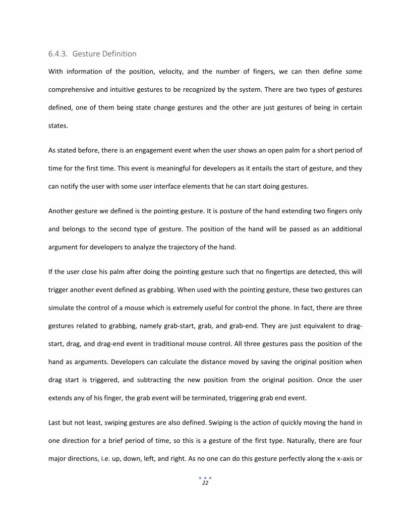
7. Application Architecture
The previous section describes our algorithm for recognizing the gesture performed. In this section we
will be describing the structure of the application and its implementation. Basically, the application can
be divided into two parts. One part is focused on processing the input frames and computes the
gestures in C++. The other part of the application is focused on Android related functions and is written
in Java.
7.1. Native C++ Part
For efficiency concern, the gesture recognition part is written in C++. In fact, the functions of the
OpenCV library are all written in C++, its Java functions are just wrapper for the underneath function
calls. Writing in the native programming language can save us from the trouble of passing variables
between Java and C++ with Java Native Interface (JNI).
In the native C++ part, we created several helper classes to facilitate the process of gesture recognition.
The first class is SkinDetector, it loads the SPM from a YAML file. Give an image in YCrCb format, it
will do the processing described in section 6.2 and output a binary mask. Then BlobDetector will then

25
take this mask to locate the blobs and output a vector of objects of the class Blob. With the help of
BlobManager, the states of the tracked blobs will be updated. It also manages the creation and
deletion of blobs stored in the main blob vector. Finally we call the getGesture method of each Blob
object to compute the gestures and return the code of gestures detected along with the position
arguments passed back to Java.
1.1. Java Part
In the Java part, the most important class we created is GestureServer. This class is responsible for
connecting to the camera. It sets the parameters of the camera and gets the frames from it, then pass
the address of the image to native C++ for processing. It then waits for the code of the gesture that the
user has performed to be returned, and call the corresponding event listeners with the returned
arguments if there is one registered.
Following the design principles of Java, we created a separate abstract Java interface called
GestureListener. This interface basically does nothing because it is just a shell empty for developers
to fill in the content by implementing it. This interface has 10 methods, they follow the naming
convention of Java event listeners, i.e. onEventName. 9 of listeners correspond to the gestures we
defined before, the last one, onGestureReady, is called after the GestureServer has started running.
In Android, an activity is equivalent to a window on desktop computers. If a developer wish to
incorporate hand gesture to his application, he could just extend the GestureActivity class which
itself is also a subclass of the standard Android Activity class. This class handles the asynchronous
loading of OpenCV library and control the life cycle of GestureServer. This class has also implemented
the empty listener interface, so developer can override only the methods they need.
The following graph shows the basic structure of the system.
26
GestureActivity
Camera
SkinDetector
BlobDetector
frame
mask
BlobManagerBlobs
Blob.getGesture()
GestureListenerGestureServer
request frame
Gesture,arugments
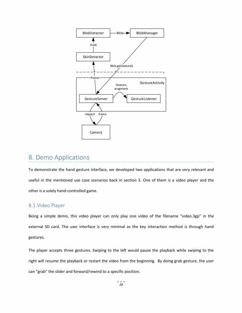
8. Demo Applications
To demonstrate the hand gesture interface, we developed two applications that are very relevant and
useful in the mentioned use case scenarios back in section 3. One of them is a video player and the
other is a solely hand-controlled game.
8.1. Video Player
Being a simple demo, this video player can only play one video of the filename “video.3gp” in the
external SD card. The user interface is very minimal as the key interaction method is through hand
gestures.
The player accepts three gestures. Swiping to the left would pause the playback while swiping to the
right will resume the playback or restart the video from the beginning. By doing grab gesture, the user
can “grab” the slider and forward/rewind to a specific position.
27
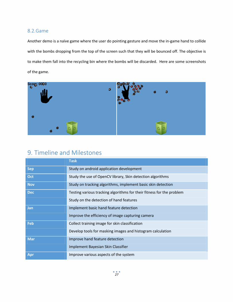
8.2. Game
Another demo is a naïve game where the user do pointing gesture and move the in-game hand to collide
with the bombs dropping from the top of the screen such that they will be bounced off. The objective is
to make them fall into the recycling bin where the bombs will be discarded. Here are some screenshots
of the game.
9. Timeline and Milestones Task
Sep Study on android application development
Oct Study the use of OpenCV library, Skin detection algorithms
Nov Study on tracking algorithms, implement basic skin detection
Dec Testing various tracking algorithms for their fitness for the problem
Study on the detection of hand features
Jan Implement basic hand feature detection
Improve the efficiency of image capturing camera
Feb Collect training image for skin classification
Develop tools for masking images and histogram calculation
Mar Improve hand feature detection
Implement Bayesian Skin Classifier
Apr Improve various aspects of the system

28
10. Future Work
10.1. Adaptive Skin Detection
Currently, the skin detector performs poorly when there is significant change of lighting conditions. This
is due to the fact that the parameters are fixed and are not adaptive to the environment. In fact, after
we get the detected skin mask, we can update the SPM by calculating the skin-color histogram and all-
color histogram online. As long as the lighting condition changes gradually, this method should give
certain extent of robustness against different illumination.
Argyros et al suggested that by using a weight average of the trained offline from the training set
and the online computed one, we can obtain a posterior probability that reflects the recent appearance
of skin-colored objects3.
In fact, the appearance of the head also gives us a hint of the skin tone under the current light sources. We
can compute the histograms using pixel on both the hand and face to generate a more suitable SPM. There
exists a number of face detection algorithms. If we incorporate these face classifier into our system, we
believe the detection rate will be much better. However, we don’t know the cost of introducing another task
running real task. It may be a huge burden for handheld devices. All these need to be searched in the future.
10.2. Tracking with Momentary Occlusion
In the current system, once the hand blob is overlapped with another blob, the “further one” is removed
from the memory. However, sometimes when the hand is performing the swipe gesture, the hand may
momentarily occlude the head, and the reappear as a new blob. With Kalman filter, we can actually allow a
blob to be lost for a few frames and estimate the position of the hand by prediction without correction
before deleting it from the memory.
3 (Argyros & Lourakis, 2005) Tracking Skin-colored Objects in Real-time. . Retrieved April 19, 2013, from
http://www.ics.forth.gr/~argyros/mypapers/2005_xx_book_Cutting_Edge_Robotics_Book_2D_tracking.pdf

29
11. Conclusion
Smartphone’s nature of mobility and hardware limitation brings greater difficulty to problem of gesture
recognition. In this project, we developed an efficient system for real time hand gesture recognition that
works well in ambient light source environment. However, the different light conditions in different
settings remain a challenge for us. In addition, when the background is full of skin-colored objects like
wooden furniture, the detection would fail miserably. We conclude that the system only has robust
performance in controlled environment and much improvement still have to be made in order for the
system to adapt to the surroundings.
12. References Argyros, A. A., & Lourakis, M. I. (2005). Tracking Skin-colored Objects in Real-time . In Cutting Edge Robotics
Book.
Elgammal, A., Muang, C., & Dunxu, H. (2009). Skin Detection - a Short Tutorial.
Farago, P. (2013, Feb 18). China Knocks Off U.S. to Become World's Top Smart Device Market. Retrieved from
Flurry: http://blog.flurry.com/bid/94352/China-Knocks-Off-U-S-to-Become-World-s-Top-Smart-
Device-Market