fusionneuse
TRANSCRIPT

8/10/2019 fusionneuse
http://slidepdf.com/reader/full/fusionneuse 1/94
Operating Instructions
X75 Fusion Splicer Series 8000

8/10/2019 fusionneuse
http://slidepdf.com/reader/full/fusionneuse 2/94

8/10/2019 fusionneuse
http://slidepdf.com/reader/full/fusionneuse 3/94
Contents
1 X75 Fusion Splicer, Overview
2 Preparatiss
3 Parameters and Programs
4 Splicing
5 Ending of Operation
6 Troubleshooting and Maintenance
7 Supplements / Changes / Notices
Index
Appendix A: Accessories

8/10/2019 fusionneuse
http://slidepdf.com/reader/full/fusionneuse 4/94
Important
Please read these operating instructions carefully to ensure that your fusion splicer func-
tions flawlessly, and that it fulfills your expectations. Perform all necessary service andmaintenance work on your fusion splicer regularly with the help of this manual. At mostcare should be exercised in order to prevent damage.
If you have any queries whatsoever, please contact the trained specialists at your servicecenter.
Improper or insufficient maintenance may impair the operating performance of your fusionsplicer.
All liability borne by the manufacturer, as well as the guarantee, are null and void if thefusion splicer is tampered with by unauthorized persons.
NOTE For reasons of clarity, these operating instructions do not provide detailed information forall versions of the product and cannot, therefore, take every possible installation, operationor maintenance situation into consideration. If you require further information, or if particu-lar problems arise which are not covered in enough detail in the operating instructions, donot hesitate to contact the Corning Equipment Service Department for the necessary infor-mation.
These operating instructions do not form part of a previous or existing agreement, commit-ment or legal relationship, nor are they intended to amend or modify any such arrange-ment. All obligations on the part of Corning arise exclusively from the relevant salescontract which also contains the only valid and comprehensive warranty conditions. Theoperating instructions neither extend nor limit the contractual warranty conditions.

8/10/2019 fusionneuse
http://slidepdf.com/reader/full/fusionneuse 5/94
Addresses
If your fusion splicer requires service please send it to:
Siemens Dematic AGSD EA 32 / GeräteserviceWarenannahmeRupert-Mayer Straße 44
D-81359 Munich, Germany
Tel. +49-89-72222068Fax +49-89-72248324
If you have technical questions or questions regarding our training program, please con-tact:
Corning Cable Systems GmbH & Co. KG
Abteilung PLM TSProfilstraße 4
D-58093 Hagen, Germany
Tel. +49-2331-3571145, 3571146, 3571155 or 3571402Fax +49-2331-3571309

8/10/2019 fusionneuse
http://slidepdf.com/reader/full/fusionneuse 6/94
Definitions for Terminology used in Warnings
The following definitions apply to the terminology used in the warnings:
Danger
In these operating instructions, as well as in warnings on the products themselves, thisterm means that death, serious injury or substantial property damage will result if the rele-vant precautions are not observed.
Warning
In these operating instructions, as well as in warnings on the products themselves, thisterm means that death, serious injury or substantial property damage may result if the rel-evant precautions are not observed.
Caution
In these operating instructions, as well as in warnings on the products themselves, thisterm means that slight injury or property damage may result if the relevant precautions arenot observed.
Note
In these operating instructions, this term makes reference to important information aboutthe product, or the relevant part of the operating instructions to which particular attentionmust be paid.
QualifiedPersonnel
In these operating instructions, as well as in warnings on the products themselves, thisterm means persons who are familiar with start-up, operation and maintenance of electri-cal equipment, and who are suitably qualified for the work they perform.

8/10/2019 fusionneuse
http://slidepdf.com/reader/full/fusionneuse 7/94

8/10/2019 fusionneuse
http://slidepdf.com/reader/full/fusionneuse 8/94

8/10/2019 fusionneuse
http://slidepdf.com/reader/full/fusionneuse 9/94
X75 Fusion SplicerPassword Request
Operating Instructionsrevision: 06/01
Password Request
Activating thePasswordRequest
The fusion splicer must be opened in order to activate or deactivate the password request.
DANGER The fusion splicer or electrically operated accessories may only be opened by suitablyqualified personnel.
Switch the fusion splicer off and disconnect it from the power supply (power supply plugand 12V battery supply)!
Two phillips head screws are located on the left of the housing and two on the right. Thesemust be removed in order to open the housing. The switch for activating and deactivatingpassword request is on the printed circuit board visible once the housing has been opened
(switch in ON position: password request activated).If password request is deactivated, the stored password is deleted as soon as the fusionsplicer is switched on again. However, if you reactivate password request without havingpreviously switched the fusion splicer on and off, the old password is retained.
No password is stored when request is reactivated. A new password must therefore first bedefined.
Entering thepassword
A password consists of an arbitrary sequence of five input keys. If you attempt to change aparameter when password request is activated, the message “Enter Password” appears. Ifan incorrect password is entered, the parameter change is not saved to memory. This alsoapplies to a change of password, i.e. a new password cannot be defined unless the current

8/10/2019 fusionneuse
http://slidepdf.com/reader/full/fusionneuse 10/94
Operating Instructionsrevision: 06/01
X75 Fusion SplicerPassword Request
password is known. To redefine the password, select the parameter “Password” and pro-ceed according to the following flow chart.
Change password? Enter password?
Only if password already exists
Enter new password
Confirm password Password wrong
Operator menu

8/10/2019 fusionneuse
http://slidepdf.com/reader/full/fusionneuse 11/94

8/10/2019 fusionneuse
http://slidepdf.com/reader/full/fusionneuse 12/94
Operating Instructionsrevision: 06/01
X75 Fusion SplicerX75 Fusion Splicer, Overview
1-2
General
The X75 Fusion Splicer is suitable for producing reliable, low-loss splices of optical fibers.
It can be used for all common single-mode and multimode fibers with a cladding diameterof 125 µm and coating diameters of 250 to 900 µm.
Due to its L-PAS (Lens-Profile Alignment System) video image evaluation with two CCDcameras and an optic system, the X75 Fusion Splicer enables the fiber alignment, end
face quality inspection, fiber offset detection, contamination detection and splice loss esti-mation during fully atomatic splice procedure by the press of one button.

8/10/2019 fusionneuse
http://slidepdf.com/reader/full/fusionneuse 13/94
X75 Fusion SplicerX75 Fusion Splicer, Overview
Operating Instructionsrevision: 06/01
1-3
Equipment Overview
2
3
5
4
6
1
4
1 Power Supply Port
2 Heat-Shrink Oven Socket
3 Splicing Unit
4 Keyboard
5 Monitor
6 Ports for Additional Functions

8/10/2019 fusionneuse
http://slidepdf.com/reader/full/fusionneuse 14/94
Operating Instructionsrevision: 06/01
X75 Fusion SplicerX75 Fusion Splicer, Overview
1-4
Splicing Unit
L-PAS VideoImage Evalua-tion System
The X75 Fusion Splicer is equipped with the L-PAS Video Image Evaluation System.The position and quality of the fiber ends are evaluated by a video image evaluation sys-tem which uses two cameras and a magnifying optic.
By evaluating the video image of both fiber views, the fiber endface quality, dirt andmechanical damages as well as fiber offset are detected, a fast fiber alignment is enabledand the splice loss is estimated.
The image of both fiber views is shown simultaneously on the monitor.
1 Electrode Flap
2 Electrodes
3 Fiber guides (silicon v-grooves)
4 Holder flaps
5 Clamping flaps
1
2
3
45 54

8/10/2019 fusionneuse
http://slidepdf.com/reader/full/fusionneuse 15/94
X75 Fusion SplicerX75 Fusion Splicer, Overview
Operating Instructionsrevision: 06/01
1-5
Monitor The LCD monitor shows the fibers from two different perspectives (along the X and Yaxes).
Keyboard The keyboard consists of 6 keys with the following functions:
Enter key: The displayed operation is performed or the previously entered value isacknowledged.
Open or exit parameters menu.
Scroll back to previous line.
Scroll forward to next line.
Increase displayed value.
Reduce displayed value.

8/10/2019 fusionneuse
http://slidepdf.com/reader/full/fusionneuse 16/94
Operating Instructionsrevision: 06/01
X75 Fusion SplicerX75 Fusion Splicer, Overview
1-6
Terminals forAdditionalFunctions
Serial Interface Splicing parameters or the contents of the splice data memory can be read out to a printeror a computer via the RS 232c serial interface. The serial interface at the fusion splicer isconfigured for use with the XON/OFF protocol. Asynchronous data transmission is accom-
plished with one start bit, eight data bits and one stop bit. The parity bit is not used.
Video Output You can connect a standard European monitor (CCIR, 625 lines) with an input impedanceof 75 Ω or higher to this output. Use a commercially available coaxial cable with RCA plug.
1 RS 232c Serial Interface
2 Video Output
1 2

8/10/2019 fusionneuse
http://slidepdf.com/reader/full/fusionneuse 17/94
X75 Fusion SplicerX75 Fusion Splicer, Overview
Operating Instructionsrevision: 06/01
1-7
Technical Data
Fiber Requirements: cladding diameter: 125 µm
coating diameters: 250 to 900 µm
Fiber Display: 140 mm (5.5“) LCD monitor
Magnification: approximately 100 times
Fiber Alignment: fully automatic, automatic and manual
(Z axis)
Typical splice loss for identical stand-ard single-mode fibers:
< 0.05 dB
Tensile Test: selectable, 2.5 N
Number of Splicing Programs: 3 fixed programs4 special programs10 user programs
Video Output: CCIR Output (75 Ω)
Operating Temperature: -5˚C to 45˚C
Storage Temperature: -40˚C to 70˚C
Dimensions Basic Unit (L x W x H): 208 x 185 x 100 mm
Weight: 2.1 kg

8/10/2019 fusionneuse
http://slidepdf.com/reader/full/fusionneuse 18/94
Operating Instructionsrevision: 06/01
X75 Fusion SplicerX75 Fusion Splicer, Overview
1-8

8/10/2019 fusionneuse
http://slidepdf.com/reader/full/fusionneuse 19/94
X75 Fusion SplicerPreparatiss
Operating Instructionsrevision: 06/01
2-1
2 Preparatiss
Contents Page
Putting the Fusion Splicer into Operation ...................................................................................................... 2-2
Supply Power ......................................................................................................................................... 2-2
Switching the Fusion Splicer On ............................................................................................................ 2-2
Preparing the Fiber Ends............................................................................................................................... 2-4
Stripping the Coating.............................................................................................................................. 2-4
Cleaning the Fiber .................................................................................................................................. 2-5
Cleaving the Fiber .................................................................................................................................. 2-5
Inserting the Fiber .......................................................................................................................................... 2-6250 µm Coating...................................................................................................................................... 2-6
Other Coating Diameters........................................................................................................................ 2-7
Adjusting Monitor Brightness ......................................................................................................................... 2-7
Checking the Fiber End Faces....................................................................................................................... 2-8

8/10/2019 fusionneuse
http://slidepdf.com/reader/full/fusionneuse 20/94
Operating Instructionsrevision: 06/01
X75 Fusion SplicerPreparatiss
2-2
Putting the Fusion Splicer into Operation
DANGER In order to assure safe operation, the fusion splicer must be placed into operation and
properly operated by qualified personnel under consideration of the warnings included inthese operating instructions. Non-observance may lead to death, severe bodily injury orsubstantial property damage.
Supply Power Connect the fusion splicer to supply power (see operating instructions for the powerpack or the rechargeable battery).
Switching theFusion SplicerOn
- Before switching the fusion splicer on, make sure that both electrodes are properlyseated (see »Replacing the Electrodes« on page 6-18).
DANGER Never switch the fusion splicer on without electrodes. The fusion splicer may otherwisebe damaged!
- Press the key to switch the fusion splicer on.
- After switching on, the software version installed is dis-played at the monitor and a self-test is performed. The elec-trodes are automatically cleaned if selected with a cleaningarc which is carried out with closed electrode flap.
- A status report showing selected settings is displayed at themonitor.

8/10/2019 fusionneuse
http://slidepdf.com/reader/full/fusionneuse 21/94
X75 Fusion SplicerPreparatiss
Operating Instructionsrevision: 06/01
2-3
NOTE The fusion splicer should only be operated with the battery when the black bar graph
indicates more than 33% charging. Never place the fusion splicer into storage with adischarged battery. Always recharge the battery at the end of each work day.
NOTE The fusion splicer switches off automatically in the power pack and the battery modes ifno key has been activated for a given period of time. Press the key to switch the
fusion splicer back on.
- The positioning slides are then automatically advanced tothe insertion position.
- In battery mode, the charge level of the battery is displayed.
If the charge level is too low to operate the unit, the “batterydischarged” message appears at the monitor and the unit isswitched off automatically. In this case charge the battery(see operating instructions for the rechargeable battery).

8/10/2019 fusionneuse
http://slidepdf.com/reader/full/fusionneuse 22/94
Operating Instructionsrevision: 06/01
X75 Fusion SplicerPreparatiss
2-4
Preparing the Fiber Ends
NOTE Minimum splice loss can only be achieved if the fiber ends are prepared with great care.
Preparation of the fiber ends includes the following steps:
• Stripping the coating
• Cleaning the fibers
• Cleaving the fibers with a suitable cleaver
• Evaluating the fiber end faces at the monitor
Please refer to the operating instructions included with your cleaver.
Stripping theCoating
Remove the coating from the end of the fiber over a length of about 50 mm.
1
2
3 1 Stripping length (approx. 50 mm)2 Uncoated fiber
3 Coating

8/10/2019 fusionneuse
http://slidepdf.com/reader/full/fusionneuse 23/94
X75 Fusion SplicerPreparatiss
Operating Instructionsrevision: 06/01
2-5
Cleaning theFiber
Clean the fiber ends over a length of approx. 100 mm (coating and uncoated fiber) with alint-free paper towel dampened with alcohol.
DANGER Risk of fire exists if solvents are spilled.
Cleaving theFiber
Use a suitable cleaver, e.g. cleaver S46999-M9-A8, to cleave the fiber. Select the correctfiber guides for the cleaver (Fiber Optic Cleaver A8: Universal fiber guide for 250 to 900 µmcoating diameter).
- Open the flap (pos. 4) at the cleaver and lay the fiber with coating diameter 250 µm into
the cleaver such that the end the coating is aligned with the “10 mm” mark. With coatingdiameters greater than 250 µm align with the mark at 15.
1
2
3
1 Cleave length: 10 mm (250 µm)
or 15 mm (>250 µm)2 Uncoated fiber
3 Coating
4

8/10/2019 fusionneuse
http://slidepdf.com/reader/full/fusionneuse 24/94
Operating Instructionsrevision: 06/01
X75 Fusion SplicerPreparatiss
2-6
- Close the flap (4) at the cleaver and press it down slowly and carefully. Open the flapbefore removing the cleaved fiber in order to avoid damaging the fiber end face.
NOTE If you press the flap down too quickly, you will obtain a poor quality fiber end face and the
diamond blade may be damaged.
Inserting the Fiber
250 µm Coating - Open the electrode flap (pos. 1), the holder flap (pos. 2) and the clamping flaps(pos. 3).
- Place the fiber (pos. 4) into the v-groove so that the end of the fiber lies between theelectrode tips.
NOTE Make sure that the fiber end is visible at the monitor after it has been inserted. Poorsplicing quality may otherwise result, or the positioning elements may not demonstrateadequate travel.
- First close the holder flap (pos. 2).
- Hold the fiber straight to ensure that it lies within the groove of the clamping mecha-
nism. Then close the clamping flap (pos. 3).- Now insert the second fiber on the other side in the same manner.
- Close the electrode flap (pos. 1).

8/10/2019 fusionneuse
http://slidepdf.com/reader/full/fusionneuse 25/94
X75 Fusion SplicerPreparatiss
Operating Instructionsrevision: 06/01
2-7
250 µm Coating
Other CoatingDiameters
- Please note that the coating diameter must be adapted in the parameter menu, see»Significance of the Parameters« on page 3-13.
Adjusting Monitor Brightness
NOTE Monitor brightness can be only changed in the main menu.
- Press the or the key until the desired brightness is obtained.
Increase monitor brightness with the key.
Decrease monitor brightness with the key.
1 Electrode Flap
2 Holder Flap
3 Clamping Flaps
4 Fiber
123
4
2 3

8/10/2019 fusionneuse
http://slidepdf.com/reader/full/fusionneuse 26/94
Operating Instructionsrevision: 06/01
X75 Fusion SplicerPreparatiss
2-8
Checking the Fiber End Faces
NOTE Good splicing results can only be obtained with good end face quality.
After inserting the fiber in the fusion splicer and before ignition of the arc, the fiber endscan be observed on the monitor.If more time is needed select the menu item “Search fibers?” The fiber ends are moved tothe center of the monitor.
- If the quality of the endface is poor, especially when the fusion splicer gives out a warn-ing, the fiber end must be prepared again.
NOTE As soon as you notice that endface quality is poor, you can interrupt the alignment
operation by activating the key.
Bad GoodThe fiber ends must be:
• Clean
• Free of noses and cracks
• Flat
• Perpendicular to the fiber axis

8/10/2019 fusionneuse
http://slidepdf.com/reader/full/fusionneuse 27/94

8/10/2019 fusionneuse
http://slidepdf.com/reader/full/fusionneuse 28/94
Operating Instructionsrevision: 06/01
X75 Fusion SplicerParameters and Programs
3-2
Cleaving Quality ...................................................................................................................................3-17
Optimizing Parameters for Single-mode Fibers ...........................................................................................3-18
Required Accessories...........................................................................................................................3-18
General Rules.......................................................................................................................................3-19
Fusion Current and Fusion Time..........................................................................................................3-19
Ambient Temperature...........................................................................................................................3-19
Procedure.............................................................................................................................................3-19
Optimizing Parameters for Multimode Fibers...............................................................................................3-21
“P t M “

8/10/2019 fusionneuse
http://slidepdf.com/reader/full/fusionneuse 29/94
X75 Fusion SplicerParameters and Programs
Operating Instructionsrevision: 06/01
3-3
“Parameter Menu“
General
Parameters can be matched to ambient conditions and to different types of fiber in the
parameter menu. The parameters menu is subdivided into “Options / Languages”, “Pro-gram selection” and “Data output”.

8/10/2019 fusionneuse
http://slidepdf.com/reader/full/fusionneuse 30/94
Operating Instructionsrevision: 06/01
X75 Fusion SplicerParameters and Programs
3-4
Open / Exit
The “parameter menu“ is opened by pressing the key with closed electrode flap. Thedisplay returns to the main menu when the key is activated from within the parametermenu (see diagram).
“Options / Language“ Menu

8/10/2019 fusionneuse
http://slidepdf.com/reader/full/fusionneuse 31/94
X75 Fusion SplicerParameters and Programs
Operating Instructionsrevision: 06/01
3-5
“Options / Language“ Menu
Parameters selected in the “Options / Language“ menu effect all programs.
NOTE Parameters in the “Options / Language“ menu can only be changed or reset if passwordquery has been deactivated, or if the correct password is entered.
Common
Parameters
Open menu: –› parameters menu –› options / languages –› common parameters.
Parameter Significance Values (default)
Password If password query is activated, parameterscan only be changed and user programs
can only be deleted after the correct pass-word has been entered. See red sheet atthe beginning of chapter 1.
-

8/10/2019 fusionneuse
http://slidepdf.com/reader/full/fusionneuse 32/94
Operating Instructionsrevision: 06/01
X75 Fusion SplicerParameters and Programs
3-6
Splice Memory Stores up to 250 splice loss values. Storedvalues can be displayed at the monitor (see»Displaying the Splice Memory at the Moni-tor« on page 4-9) or printed via the serialinterface (see »Data Output Menu« onpage 3-16). The parameters in this menuhave the following effects:
OFF: No splice loss values are stored tomemory.
Automatic: splice loss values values arestored to memory automatically.
Manual:
The operator is requested to man-ually store the splice loss values after eval-
uation of the splice.
Delete: The splice memory is deleted in itsentirety.
off/autom
.
/manual/ delete
Cleaning Current Arc temperature during cleaning 10.0 to 16.0 mA
Cleaning Time Ignition time during cleaning 0.05 to 0.30 s
BatteryDisconnect Time
Elapsed time until automatic fusion splicershut-down
2 to 60 min, 10 min
Parameter Significance Values (default)

8/10/2019 fusionneuse
http://slidepdf.com/reader/full/fusionneuse 33/94
X75 Fusion SplicerParameters and Programs
Operating Instructionsrevision: 06/01
3-7
Language
Open menu: –› parameters menu –› options / languages –› language.This function allows for selection of the desired operating language.
Available languages depend upon the installed software version.
Altitude aboveSea Level
In order to assure uniform, high-qualitysplices, the selected altitude must roughlycorrespond to actual altitude.
0 to 4000 m, 550 m
Alarm Limit As soon as the estimated loss value isequal to or exceeds the selected alarmlimit, a brief warning signal sounds.
OFF / 0.05 to 0.2 dB
Parameter Significance Values (default)
D German DK Danish
GB English H Hungarian
F French PL Polish
E Spanish CZ Czech
I Italian C Chinese
NL Dutch GUS Russian
IRA Farsi POR Portuguese
Heat-shrink Open menu: › parameter menu › options / languages › heat shrink oven

8/10/2019 fusionneuse
http://slidepdf.com/reader/full/fusionneuse 34/94
Operating Instructionsrevision: 06/01
X75 Fusion SplicerParameters and Programs
3-8
Heat-shrinkOven
Open menu: –› parameter menu –› options / languages –› heat-shrink oven.
Parameter Significance Values (default)Heat-shrinkParameters
If you intend to control the heat-shrink ovenfrom the fusion splicer, select “internal”. If“external” is selected, heat-shrinking is con-trolled by the parameters selected at theheat-shrink oven.
internal / external
Heating Time If “internal” heat-shrink parameters havebeen selected, the internally selected heat-ing time is used.
10 to 250 s in steps of10
, 60 s
Temperature If “internal” heat-shrink parameters havebeen selected, the internally selected tem-
perature is used.
80 to 150 ˚C, 120 °
C
Service Data Open menu: –› parameter menu –› options / languages –› service data

8/10/2019 fusionneuse
http://slidepdf.com/reader/full/fusionneuse 35/94
X75 Fusion SplicerParameters and Programs
Operating Instructionsrevision: 06/01
3-9
Service Data
Open menu: › parameter menu › options / languages › service data.
Parameter Significance Values (default)
Operating Hours Total number of operating hours -
Splices Total number of splices -
Cleaning Cycle Number of splices performed before opera-tor is reminded to clean the electrodes
50 to 700 in steps of 10,500
Reset Counter:XX Reset “Cleaning cycle” counter to 0 yes /no
ReplacementInterval
Number of splices performed before opera-tor is reminded to replace the electrodes
700 to 7000 in steps of100, 5000
Reset Counter:
XXX
Reset “Replace Electrodes” counter to 0 yes/no
Configuration Open menu: –› parameters menu –› options / languages –› device configuration

8/10/2019 fusionneuse
http://slidepdf.com/reader/full/fusionneuse 36/94
Operating Instructionsrevision: 06/01
X75 Fusion SplicerParameters and Programs
3-10
Configuration
Open menu: › parameters menu › options / languages › device configuration
Parameter Significance Values (default)
ElectrodeCleaning
Automatic electrode cleaning with closedelectrode flap after the splicer has beenswitched on.
on / off
Status Report Current settings are displayed after thesplicer is switched on.
on / off
ContaminationDetection Sensi-tivity
- high / low
“Program Selection“ Menu

8/10/2019 fusionneuse
http://slidepdf.com/reader/full/fusionneuse 37/94
X75 Fusion SplicerParameters and Programs
Operating Instructionsrevision: 06/01
3-11
Program Selection Menu
Program
Descriptions
Program Applications
Fixed Programs Standard Single-mode (SM)
1 For all standard, single-mode fibers (matched cladding ordepressed cladding).
Multimode50 µ
m (MM50)2 For gradient index fibers with a core diameter of 50 µ m. Position-
ing and loss estimation are performed by video image evaluation.
Multimode62.5 µ
m (MM62)3 For gradient index fibers with a core diameter of 62.5 µ
m. Position-ing and loss estimation are performed by video image evaluation.
Special Programs DS Single-mode 1 For dispersion-shifted single-mode fibers. Parameters are opti-mized for this fiber type.
LS Single-mode 2 For lambda-shifted single-mode fibers. This fiber type is a refine-ment of the DS fiber.
CS Single-mode 3 For cut-off-shifted single-mode fibers
TrueWave Fibers 4 For TrueWave fibers.
LEAF Fibers 5 For LEAF fibers.
Titanium-CoatedSingle-mode
6 For standard titanium-coated single-mode fibers.
Program Applications

8/10/2019 fusionneuse
http://slidepdf.com/reader/full/fusionneuse 38/94
Operating Instructionsrevision: 06/01
X75 Fusion SplicerParameters and Programs
3-12
Creating UserPrograms
Parameters for preset and special programs cannot be changed by the user. If you need toadapt parameters to a special fiber type, a user program must first be created. Proceed asfollows:
- Open the parameters menu with the key.
- Select “user programs” with the or the key and acknowledge with .
- Existing user programs are now displayed.- Select “new program” with the or the key and acknowledge with .
- Enter a program name. The name may include a maximum of 10 characters. The keys havethe following functions:
and : change character at current cursor position.
and : move cursor.: acknowledge entry.
- Select the program to be copied with the or the key. A fixed, a special or a userprogram can be selected.Acknowledge with .
User Programs 1…10 All available programs, i.e. preset programs, special programs andalready existing user programs, can be used as the basis for the
creation of a new user program.The parameters from the selected program are copied into thenew user program. The parameters can then be edited in the newuser program. This allows for adaptation to special circumstancesand additional fiber types. Up to 10 user programs can be created.
Program Applications
- The user program has now been created, and is identical to the program which was

8/10/2019 fusionneuse
http://slidepdf.com/reader/full/fusionneuse 39/94
X75 Fusion SplicerParameters and Programs
Operating Instructionsrevision: 06/01
3-13
copied. The parameters are now displayed and can be changed as desired.
NOTE At first, use the preset parameters for fusion current and fusion time (for pre-fusion and
fusion) from the copied preset or the special program. If the splicing results obtained withthese values are not adequate, see »Optimizing Parameters for Single-mode Fibers« onpage 3-18, or see »Optimizing Parameters for Multimode Fibers« on page 3-21.
Significance of
the Parameters
The individual parameters have the following significance:
Parameter Significance Values
Fiber Type When the fiber type is changed, the param-eters in the user program are overwritten
with the standard parameters for the newlyselected fiber type. The program name forthe user program remains unchanged.
Z-gap Distance between the fiber ends prior to
fusion.
2.0 to 10.0 µ
m
Autofeed Pushing fiber ends together beyond thepoint of contact (over-travel) 0.0 to 10.0 µm
max. xy-offset Maximum offset of both fiber ends in x andy axis, without an indication on the display.
5.0 to 15.0 µm, 7.0 µm
Parameter Significance Values

8/10/2019 fusionneuse
http://slidepdf.com/reader/full/fusionneuse 40/94
Operating Instructionsrevision: 06/01
X75 Fusion SplicerParameters and Programs
3-14
Pre-fusionCurrent
Temperature of the arc during pre-fusion 10.0 to 20.0 mA
Pre-fusion Time Time between ignition of arc and start offeeding operation
0.0 to 10.0 s
Fusion Current Temperature of the arc during primaryfusion
10.0 to 20.0 mA
Fusion Time Ignition time during primary fusion 0.0 to 10.0 sTensile Test Testing of the splice for tensile strength.
The tensile test is not possible for attenua-tion splices.
yes / no
Coating Diameter Change of the insertion position. 250/500/900 µm
Parameter Significance Values
Editing and - Open the parameter menu with the key.

8/10/2019 fusionneuse
http://slidepdf.com/reader/full/fusionneuse 41/94
X75 Fusion SplicerParameters and Programs
Operating Instructionsrevision: 06/01
3-15
Renaming UserPrograms
- Select the user program to be edited (see »Creating User Programs« on page 3-12)and acknowledge.
- Parameters can now be changed: and : change the value of the displayed parameter.
: acknowledge and save the changed value.
and : scroll to previous or next parameter, without storing any changes tomemory.
- : exit parameter menu.
- The name of the user program can be selected with the key, and can then bechanged in the same way as for the creation off new user programs.
NOTE Editing and renaming of user programs are only possible if password request has beendeactivated, or if the correct password is entered.
Deleting UserPrograms
- Open the parameter menu and select the user program to be deleted with the or thekey, but do not acknowledge.
- Press the key and acknowledge deletion of the program with the key.
NOTE The deletion of user programs is only possible if password request has been deactivated,or if the correct password is entered.
Data Output Menu

8/10/2019 fusionneuse
http://slidepdf.com/reader/full/fusionneuse 42/94
Operating Instructionsrevision: 06/01
X75 Fusion SplicerParameters and Programs
3-16
p
Open menu –› parameters menu –› data output
NOTE Parameters in the data output menu can only be changed or reset if password query hasbeen deactivated, or if the correct password is entered.
Parameter /
Function
Significance Setting Range
Baud Rate Data transmission speed at the RS 232cinterface
150/300/600/1200/ 2400/4800/9600 baud
Splice MemoryPrinting
- yes / no
Fusion Parame-ters Printing
- yes / no
Special Program for TrueWave Fiber

8/10/2019 fusionneuse
http://slidepdf.com/reader/full/fusionneuse 43/94
X75 Fusion SplicerParameters and Programs
Operating Instructionsrevision: 06/01
3-17
Cleaving Quality TrueWave fiber reacts with great sensitivity to worn or damaged cleavers. If the cleaver is
not in flawless condition, splintering occurs in the coating.As a rule, this damage is not allways visible at the display and is thus not recognized bythe splicer. In general, illuminated spots appear during fusion at the splice joint. Thisresults in extremely poor splicing results (0.5 dB and more), which are normaly recognizedby the splicer. Splintering may be present if the actual cleave angle is still OK (the cleaveangle which is measured and displayed by the splicer). This problem may even occur with
cleavers which function flawlessly with other types of fiber. Use flawlessly functioningcleavers only.
Optimizing Parameters for Single-mode Fibers

8/10/2019 fusionneuse
http://slidepdf.com/reader/full/fusionneuse 44/94
Operating Instructionsrevision: 06/01
X75 Fusion SplicerParameters and Programs
3-18
The pre-selected parameters for the preset and special programs are suitable for all com-
mon fiber types. Nevertheless, an optimization of the parameters mays become neces-sary, for example:
• If special fiber types are used which demonstrate unusual characteristics or excessivecore eccentricity.
• If work is carried out at an altitude higher than than 4000 m above sea level or if theselected altitude is extremely different (see »Common Parameters« on page 3-5).
• If the ambient temperature deviates greatly from +20˚C.
NOTE The parameters can only be optimized if the electrodes are in flawless condition.
The procedure described in the following pages for the optimization of parameters is suita-ble for all common single-mode fibers.
RequiredAccessories
An attenuation measuring instrument (e.g. an OTDR, Optical Time Domain Reflectometer)should be used whenever possible for the optimization of parameters for single-mode fib-ers.
NOTE The attenuation display at the fusion splicer can only provide correct results if the parame-
ters are correctly set. It can therefore only be used for the optimization of parameters to alimited extent. Always use an external attenuation measuring instrument (e.g. OTDR, Opti-cal Time Domain Reflectometer) to check the attenuation results if possible.
General Rules The following rules apply to practically all single-mode fibers. Deviations from these rulesare only necessary for a few special fibers for example if bubbles are formed

8/10/2019 fusionneuse
http://slidepdf.com/reader/full/fusionneuse 45/94
X75 Fusion SplicerParameters and Programs
Operating Instructionsrevision: 06/01
3-19
are only necessary for a few special fibers, for example if bubbles are formed.
• The standard parameters are always used for Z gap, auto-feed and pre-fusion time.
• Pre-fusion current and fusion current are always set to the same value.
If bubbles should occur during splicing, see »Bubble Formation« on page 3-21. The cor-rective measures described there are suitable for single-mode fibers as well.
The only remaining parameters to be optimized are thus current (for pre-fusion and fusion)and fusion time.
Fusion Currentand Fusion Time
Fusion current and fusion time have, to a certain extent, the same effect on splicing qual-ity: Increasing the current has approximately the same effect as lengthening the time, i.e.the same results can be achieved with different current/time combinations.
AmbientTemperature
The preset and special programs are based upon an ambient temperature of +20˚C. If theactual ambient temperature varies greatly from this value, cleaning current, pre-fusion cur-
rent and fusion current must be appropriately adjusted:
At an ambient temperature of above +20˚C reduce current by 0.4 mA per 10˚C.At an ambient temperature of under +20˚C increase current by 0.4 mA per 10˚C.
Procedure An external attenuation test set is required for this procedure.
- Generate a user program for optimization with the “Standard Single-Mode (SM)” presetprogram (see »Creating User Programs« on page 3-12
- First produce splices with the default values for fusion current and time. Do not removethe splice from the splicer and do not start the tensile test. Measure the loss with theattenuation test set.
- Press key and initiate with “Refusion“.
Measure the loss again

8/10/2019 fusionneuse
http://slidepdf.com/reader/full/fusionneuse 46/94
Operating Instructionsrevision: 06/01
X75 Fusion SplicerParameters and Programs
3-20
- Measure the loss again.
The parameters are set correctly when the loss worsens slightly relative to the first meas-urement ( by 0.01 to 0.03 dB ). If the loss remains unchanged, the fusion current or the
time selected was too low. If the loss rises sharply, the current or the time is too high.Change either the current (prefusion current and fusion current) in steps of 0.5 mA or thetime in steps of 0.5 s.
Optimizing Parameters for Multimode Fibers

8/10/2019 fusionneuse
http://slidepdf.com/reader/full/fusionneuse 47/94
X75 Fusion SplicerParameters and Programs
Operating Instructionsrevision: 06/01
3-21
NOTE The parameters can only be optimized if the electrodes are in flawless condition.
In the case of multimode fibers, the optimization of parameters with respect to attenuationis largely non-critical. As opposed to single-mode fibers, it can be assumed that spliceattenuation is always good, if the splice demonstrates good visual characteristics. Anattenuation measuring instrument is thus not required for optimization.
With multimode fibers, pre-fusion current is generally lower than fusion current. Pre-fusiontime is also longer than for single-mode fibers.
The following problems may occur during fusion:
Symptom Possible Cause Remedy
Bubble Formation The splice is severely enlargedand irregular. The splice
breaks extremely easily. Thisproblem occurs mainly withfibers with a high core refrac-tive index (e.g. 50 µm corediameter).
Increase pre-fusion time in steps of0.1 s. At the same time, reduce pre-
fusion current in steps of 0.5 mA. Ifthis is not sufficient, reduce fusioncurrent in steps of 0.5 mA.
IncompletelyFused Splices The bright line in the center ofthe fiber is interrupted at thesplice.
If you are able to obtain an improve-ment by means of re-fusing, increasefusion time, otherwise increasefusion current.
Symptom Possible Cause Remedy

8/10/2019 fusionneuse
http://slidepdf.com/reader/full/fusionneuse 48/94
Operating Instructionsrevision: 06/01
X75 Fusion SplicerParameters and Programs
3-22
Constriction In the center of the monitor thefiber appears thinner than at
the edges.
Reduce pre-fusion current in steps of0.5 mA.

8/10/2019 fusionneuse
http://slidepdf.com/reader/full/fusionneuse 49/94
Exiting the Memory Display....................................................................................................................4-9
Printing Splice Values.............................................................................................................................4-9

8/10/2019 fusionneuse
http://slidepdf.com/reader/full/fusionneuse 50/94
Operating Instructionsrevision: 06/01
X75 Fusion SplicerSplicing
4-2
Printing Splice Values.............................................................................................................................4 9
General

8/10/2019 fusionneuse
http://slidepdf.com/reader/full/fusionneuse 51/94
X75 Fusion SplicerSplicing
Operating Instructionsrevision: 06/01
4-3
NOTE Make sure that all required splicing preparations have been performed correctly and com-pletely. If not, perform the necessary preparations to the splicer and the fiber (see chapters
2 and 3).
Each splicing operation includes:
• Arc cleaning of fiber ends.
• Alignment (Z-axis)
• Fusion, with feed along the Z-axis• Splice evaluation
Selecting the Splicing Program
The various programs and their ranges of application are described in chapter 3 »Parame-ters and Programs«. With this information you should now be able to select or create, andactivate the required program.
- Activate the desired program in the parameters menu.
- Return to the main menu with the key.
The Splicing Sequence

8/10/2019 fusionneuse
http://slidepdf.com/reader/full/fusionneuse 52/94
Operating Instructionsrevision: 06/01
X75 Fusion SplicerSplicing
4-4
After the fibers have been prepared and inserted (see chapter 2 “Preparations”), the dis-
play at your monitor will be similar to the diagram below.
- Press the key in order to start the splicing sequence. The entire splicing sequence ismenu-driven.
Fully automatic You will normally use the fully automatic splicing sequence. The selected fusion program
runs automatically.
Automatic If visible signs of dirt remain on the fiber after automatic cleaning, terminate the operationwith and select automatic mode.
You can clean as often as necessary during this process. If the fiber ends are still not cleanafter five cleaning cycles, they must be stripped and cut again.
Semi-automatic For test purposes, select the semi-automatic splicing sequence. In this mode you have toinitiate cleaning and positioning in the Z-axis individually.
Manual fiberpositioning
For special purposes you can position the optical fibers manually using keys and .

8/10/2019 fusionneuse
http://slidepdf.com/reader/full/fusionneuse 53/94
X75 Fusion SplicerSplicing
Operating Instructionsrevision: 06/01
4-5
Cleaning The fiber ends are cleaned with an electric arc.
Alignment After cleaning an evaluation of fiber endface quality and fiber offset is carried out duringalignment.
Endface QualityInspection
This inspection is performed for all programs with which fibers are spliced in the fully auto-matic or the automatic mode.
If the video image evaluation system L-PAS detects contamination or Cleave angle devia-tions of more than 3.5˚, the message “bad endfaces - fusing?” appears.
Fiber endfaces which are poorly prepared will yield high splice losses and incorrect spliceestimations data. The fibers should be prepared once again in such cases, and the cleavershould be cleaned if necessary. If the fiber cannot be prepared again (e.g. due to minimal
fiber length), the operation can continued be by pressing the key.
Fiber OffsetDetection
Dirt on the fiber or in the silicat v-slot may lead to a fiber offset detection which results in abad splice loss value. When the fiber offset exceeds the adjusted permissible value (see»Significance of the Parameters« on page 3-13) an indication appears on the display.

8/10/2019 fusionneuse
http://slidepdf.com/reader/full/fusionneuse 54/94
• The fusion parameters have been set correctly.
• Core eccentricity relative to the outside contour must be minimal.

8/10/2019 fusionneuse
http://slidepdf.com/reader/full/fusionneuse 55/94
X75 Fusion SplicerSplicing
Operating Instructionsrevision: 06/01
4-7
Chapter 6 provides examples of poor splices, possible causes and appropriate remedies.
Re-Fusing Re-fusing can be used to optimize parameters and to enhance splicing results, if theselected fusion time was too short, or if fusion current was too low.
- If the key is activated, “Fuse?” or “Fuse again?” appears at the display.This provides you with the opportunity to re-fuse the splice, i.e. to re-ignite the arc.Splice loss is displayed after re-fusing.
Tensile Test If the tensile test has been activated, the request “Tensile test?” appears at the displayafter fusion.
- Press the key to start the tensile test. If the tensile test should not be performedpress key
- “Remove fibers” appears at the display after testing.
NOTE If the tensile test has been activated, the splice loss value is not stored to the splice mem-ory until after completion of the tensile test. If you open the electrode flap without perform-ing the tensile test, the splice loss value is not stored to memory.
Removing theSplice
For removing the spliced fibers all flaps must be opened. The completed splice should beremoved immediately because 5 sec after the elctrode flap has been opened the slidesadvance to the insertion position

8/10/2019 fusionneuse
http://slidepdf.com/reader/full/fusionneuse 56/94
Operating Instructionsrevision: 06/01
X75 Fusion SplicerSplicing
4-8
advance to the insertion position.
After the message “fully automatic?” has appeared, the fusion splicer is once again ready
for operation.
Protecting the Splice
The coating must be stripped from the ends of the fibers in order to make fusion possible.In order to protect the stripped portion of the fibers, a crimp splice protector or a heat-shrink splice protector must be used. These splice protectors provide the splice withmechanical stability thereby preventing possible damage during subsequent handling.
Crimping device and heat-shrink oven are available as accessories (see chapter 7).
Splice Memory

8/10/2019 fusionneuse
http://slidepdf.com/reader/full/fusionneuse 57/94
X75 Fusion SplicerSplicing
Operating Instructionsrevision: 06/01
4-9
Activating theSplice Memory
The splice memory can be activated in the parameters menu, see »Configuration« onpage 3-10. Up to 250 values can be stored and transmitted via the RS 232c serial inter-face.
Displaying theSplice Memoryat the Monitor
If you scroll through the entire splicing sequence by repeatedly pressing the key, thecontents of the splice memory are displayed at the monitor.
You can scroll backwards and forwards within the memory with the and keys.
Deleting theLast Value
If you have to repeat the last splice you made, you can delete the associated loss valuefrom memory.
- Press the key after completion of the fusion process in order to display the contentsof the memory.
- Press key again, so that the last stored value is displayed. You can now delete thedisplayed value with the key.
Exiting theMemory Display
- The display returns to the main menu when the key is activated.
Printing SpliceValues
- Connect the printer to the serial interface at the fusion splicer with a printer cable (see»Serial Interface« on page 1-6).
- Set the printer and the fusion splicer to the same data transmission speed and selectthe function “Print splice values” (see »Data Output Menu« on page 3-16). Acknowl-edge with the key.

8/10/2019 fusionneuse
http://slidepdf.com/reader/full/fusionneuse 58/94
Operating Instructionsrevision: 06/01
X75 Fusion SplicerSplicing
4-10
5 Ending of Operation

8/10/2019 fusionneuse
http://slidepdf.com/reader/full/fusionneuse 59/94
X75 Fusion SplicerEnding of Operation
Operating Instructionsrevision: 06/01
5-1
Contents Page
Switching the Fusion Splicer Off .................................................................................................................... 5-2
Stowing Accessories...................................................................................................................................... 5-2
Switching the Fusion Splicer Off

8/10/2019 fusionneuse
http://slidepdf.com/reader/full/fusionneuse 60/94
Operating Instructionsrevision: 06/01
X75 Fusion SplicerEnding of Operation
5-2
- Simultaneously press the and keys.
The slides are automatically advanced to the transport position, after which the fusionsplicer switches off.
WARNING Always switch the fusion splicer off at the control panel. If you simply remove the powersupply plug, the slides are not advanced to the transport position. This could result indamage to the fusion splicer during transport.
Stowing Accessories
- Remove the power cable from the socket at the power supply.
- Remove any contamination and fiber scraps.
- Close the electrode flap.
- Stow the cables, the tool kit and the accessories in the fusion splicer case (see operat-ing instruction for the fusion splicer case).
6 Troubleshooting and Maintenance

8/10/2019 fusionneuse
http://slidepdf.com/reader/full/fusionneuse 61/94
X75 Fusion SplicerTroubleshooting and Maintenance
Operating Instructionsrevision: 06/01
6-1
Contents Page
Basic Procedures........................................................................................................................................... 6-2
List of Error Messages ................................................................................................................................... 6-3
Error Messages during Start-Up............................................................................................................. 6-3
General Error Messages during Operation ............................................................................................ 6-4
Error Messages during Fiber Alignment................................................................................................. 6-5
Error Messages during Splice Loss Estimation...................................................................................... 6-8
Splice Memory Error Messages ............................................................................................................. 6-9
Errors Messages during Printing............................................................................................................ 6-9
Other Errors ................................................................................................................................................. 6-10
Maintenance and Care................................................................................................................................. 6-15
Cleaning and Replacing the Protection Glass ......................................................................................................6-15
Cleaning the V-grooves........................................................................................................................ 6-17
Cleaning and Replacing the Electrodes ............................................................................................... 6-18
Basic Procedures
P d f ll i if lf ti if di l d t th f i

8/10/2019 fusionneuse
http://slidepdf.com/reader/full/fusionneuse 62/94
Operating Instructionsrevision: 06/01
X75 Fusion SplicerTroubleshooting and Maintenance
6-2
Proceed as following if malfunctions occur or if error messages are displayed at the fusionsplicer:
• If an error message occurs only once, repeat the questionable operation step. Forexample, if the “bad endfaces” message appears, prepare the fibers again.
• If the same problem occurs repeatedly, make sure that you are handling the fibers andoperating the fusion splicer as described in the operating instructions.
• If you are unable to ascertain the cause of the fault, or if the fault occurs repeatedly, the
following subsection provides you with possible causes for a variety problems, as wellas appropriate remedies.
• Some of the remedies described below require utmost care and should only be per-formed by qualified personnel in a clean working environment.
• Under no circumstances should you attempt to perform repair work which, according tothe table, may only be carried out at the service center.
NOTE The manufacturer assumes no liability for damage which results from improper executionof the following remedies.
NOTE Error messages are also indicated by means of an acoustic warning signal!
List of Error Messages
The following pages contain explanations of the error messages displayed at the monitor

8/10/2019 fusionneuse
http://slidepdf.com/reader/full/fusionneuse 63/94
X75 Fusion SplicerTroubleshooting and Maintenance
Operating Instructionsrevision: 06/01
6-3
The following pages contain explanations of the error messages displayed at the monitor,together with notes concerning remedies. The error messages are arranged in the order ofthe operations during which they might occur.
Please note that several of the error messages may have various causes and symptoms,and may therefore be listed more than once on the following pages.
Error Message Possible Cause Remedy
Error Messagesduring Start-Up
Self-test Error 1
Defective RAM. Switch off the fusion splicerand switch it back on again. Ifthe fault is repeated, the fusionsplicer must be sent to theservice center for repair.
Notify the service center of theerror number displayed.
Error 2 Defective graphic memory.
Error 3 Defective RAM and graphicmemory.
Error 4 Incorrect digitalization.
Reference switch left error right error
Left and/or right-hand limitswitch has not been actuated.Switch is faulty or slide doesnot move.
Press the key. If the errorpersists, the fusion splicermust be sent to the servicecenter for repair.
battery discharged! The power supply is not con- Make sure the power supply,
Error Message Possible Cause Remedy

8/10/2019 fusionneuse
http://slidepdf.com/reader/full/fusionneuse 64/94
Operating Instructionsrevision: 06/01
X75 Fusion SplicerTroubleshooting and Maintenance
6-4
The fusion splicer will
be switched off .
nected to the battery and AC
power operation is not possi-ble.
battery and fusion splicer are
connected properly.
The power supply is not func-tioning. The battery is notbeing charged.
The message appears eventhough the fusion splicer canbe operated with AC power.
Make sure that the greencharging indicator lamp is lit. Ifnot, check AC power supply.
The battery is faulty but ACpower operation is possible.
Replace the battery.
General Error
MessagesduringOperation
Program status [X]=... Processor crash or software
error.
Switch the fusion splicer off
and then switch it back onagain. If the error persists, thefusion splicer must be sent tothe service center for repair.
Notify the service center of theerror numbers displayed.
Error Messages Z-gap too large or fibers Fibers inserted incorrectly or Insert the fibers correctly, see
Error Message Possible Cause Remedy

8/10/2019 fusionneuse
http://slidepdf.com/reader/full/fusionneuse 65/94
X75 Fusion SplicerTroubleshooting and Maintenance
Operating Instructionsrevision: 06/01
6-5
during Fiber
Alignment
not detected wrong cleave length. »Inserting the Fiber« on page
2-6.The fibers must be centeredbetween the electrodes whenthe holder flaps are closed.
No fibers present. Insert fibers.
Fiber inserted incor- rectly
The fiber end could not befound during fiber alignment.
The fibers overlap too much,are too long or the cleavelengths are too different.
Insert the fibers correctly, see»Inserting the Fiber« on page2-6.
Fiber not detected Contaminated optical Remove contamination andi id f h
Error Message Possible Cause Remedy

8/10/2019 fusionneuse
http://slidepdf.com/reader/full/fusionneuse 66/94
Operating Instructionsrevision: 06/01
X75 Fusion SplicerTroubleshooting and Maintenance
6-6
system. coating residue from the pro-
tection glass at the optical sys-tem, see »Cleaning andReplacing the ProtectionGlass« on page 6-15.
Condensation at optical sys-tem.
The fiber image display isunclear in one or two axes.
Prevent condensation by plac-ing the fusion splicer in a room
that is not too cold prior to use.Only leave the electrode flapopen as long as absolutelynecessary during splicing.
Fiber end is no longer
detected as such by the videosystem, i.e. the fiber is eitherextremely dirty or extremelypoorly cleaved.
Clean fiber or prepare fiber
again.
Fiber offset too large Fiber contaminated or insertedi tl
Check whether the fiber isl d tl i t d i
Error Message Possible Cause Remedy

8/10/2019 fusionneuse
http://slidepdf.com/reader/full/fusionneuse 67/94
X75 Fusion SplicerTroubleshooting and Maintenance
Operating Instructionsrevision: 06/01
6-7
Offset.. µ m
The fiber offset is clearlyvisible prior to align-ment.
incorrectly. clean and correctly inserted in
the v-groove.If necessary, prepare the fiberagain and insert correctly.
Fiber guides contaminated ordamaged.
Clean the guides, see »Clean-ing the V-grooves« on page6-17.
Fiber contaminated orbad end faces - fusing?
The video system hasdetected that the total cleaveangle exceeds 3.5˚, or that theend face is contaminated.
Determine at the monitorwhich fiber end is faulty.Prepare fibers again.
Fiber offset too large Fiber contaminated or inserted
incorrectly.
Check whether the fiber is
clean and inserted correctlyinto the v-grooves.
If necessary, prepare fibersagain and insert them cor-rectly.
Fiber guides contaminated ordamaged. Clean the v-grooves (see»Cleaning the V-grooves« onpage 6-17).
Video digitizer error Video system electronics notfunctioning
Switch off the fusion splicerand switch it back on again If
Error Message Possible Cause Remedy

8/10/2019 fusionneuse
http://slidepdf.com/reader/full/fusionneuse 68/94
Operating Instructionsrevision: 06/01
X75 Fusion SplicerTroubleshooting and Maintenance
6-8
functioning. and switch it back on again. If
the error occurs again, thefusion splicer must be repairedat the service center.
You can continue working withmanual fiber alignment.
Error Messagesduring SpliceLoss Estimation
Fiber not detected Contaminated optical system. Remove contamination andcoating residue from the pro-tection glass at the optical sys-tem, see »Cleaning andReplacing the ProtectionGlass« on page 6-15.
Condensation at optical sys-tem.The fiber image display isunclear in one or two axes.
Prevent condensation by plac-ing the fusion splicer in a roomthat is not too cold prior to use.Only leave the electrode flapopen as long as absolutelynecessary during splicing.
Fiber end is no longerdetected as such by the videosystem (fibers burnt or bubbleformation).
Repeat splice.
Bad splice - fuse again?
Th t l li l
Pre-fusion parameter values tohigh
Reduce pre-fusion current orpre fusion time Time may not
Error Message Possible Cause Remedy

8/10/2019 fusionneuse
http://slidepdf.com/reader/full/fusionneuse 69/94
X75 Fusion SplicerTroubleshooting and Maintenance
Operating Instructionsrevision: 06/01
6-9
The actual splice loss
may still be OK undercertain circumstances.
high. pre-fusion time. Time may not
be set too low.Contaminated optical system. Check the image at the moni-
tor for visible signs of contami-nation with no fibers inserted.Remove contamination andcoating residue from the pro-
tection glass of the optical sys-tem (see »Cleaning andReplacing the ProtectionGlass« on page 6-15).
Splice MemoryError Messages
No data available The splice memory is empty. Make sure that the splicememory has been activated inthe parameter menu. To save adisplayed loss value acknowl-edge with .
ErrorsMessages
during Printing
Printer not ready! The printer connected to theserial interface transmits incor-
rect control characters.
Check the baud rate at theprinter and the fusion splicer.
Make sure that the printer sup-ports the XON/XOFF proto-col, and the appropriate dataformat (8 data bits, 1 stop bit,no parity).
Other Errors
The following table describes remedys for errors which are not displayed at the monitor.

8/10/2019 fusionneuse
http://slidepdf.com/reader/full/fusionneuse 70/94
Operating Instructionsrevision: 06/01
X75 Fusion SplicerTroubleshooting and Maintenance
6-10
Symptom Possible Cause Remedy
Battery mode not possi-ble, AC supply modeOK.
The battery is missing or is notconnected, or the battery fuseis faulty.
Check that the battery hasbeen correctly installed andthat the battery fuse is OK.
Install and correctly connect
the battery and/or replace thefuse. If the error persists, thefusion splicer must be sent tothe service center for repair.
Arc flickers or hisses. Electrodes dirty or eroded. Clean or replace electrodes.
The fiber does not meltduring the fusion proc-ess but buckles instead.
The splice point barelylights up during splicing.
Fusion current too low. Set correct fusion current.
The fiber buckles at thestart of the fusion proc-ess.
Pre-fusion time is too short orpre-fusion current too low.
Correct pre-fusion parameters.You can use the default valuesas a starting point.
Fibers burn away. Pre-fusion current or pre-fusion time too high.
Set the parameters (see chap-ter 3). Try using the fixed pro-
Symptom Possible Cause Remedy

8/10/2019 fusionneuse
http://slidepdf.com/reader/full/fusionneuse 71/94
X75 Fusion SplicerTroubleshooting and Maintenance
Operating Instructionsrevision: 06/01
6-11
g y g pgram for the appropriate fibertype.Auto-feed too small.
Fusion current considerablytoo high.
Charging indicator lampis not lit.
No AC power. Connect the power supply tothe electrical outlet.
Defective power supply. Service center.
Constriction Contaminated electrodes.
The arc burns irregularly.
Clean electrodes.
Symptom Possible Cause Remedy

8/10/2019 fusionneuse
http://slidepdf.com/reader/full/fusionneuse 72/94
Operating Instructionsrevision: 06/01
X75 Fusion SplicerTroubleshooting and Maintenance
6-12
g y
Fusion current too high. Reduce in steps of 0.2 to0.3 mA.
Autofeed too small. Increase in steps of 1 µm.
Pre-fusion time too long. Change only under extraordi-nary circumstances.
Reduce in steps of 0.05 s.
Pre-fusion current too high. Change only under extraordi-nary circumstances.
Reduce in steps of 0.1 mA
Z-gap too wide. Reduce Z gap in steps of
0.5 µm (do not set below3 µm).
Enlargement Autofeed too large. Reduce in steps of 1 µm.
Not fused through Fusion current too low. Increase in steps of0.2 to 0.3 mA.
Symptom Possible Cause Remedy

8/10/2019 fusionneuse
http://slidepdf.com/reader/full/fusionneuse 73/94
X75 Fusion SplicerTroubleshooting and Maintenance
Operating Instructionsrevision: 06/01
6-13
Pre-fusion time too short. Change only under extraordi-nary circumstances.
Increase in steps of 0.05 s.
Bubble or inclusion Contaminated end faces priorto splicing.
Clean end faces before fusion!
Consider increase cleaning
current by 0.2 to 0.3 mA orincrease cleaning time by0.1 s.
Poor cleave. Check cleave quality prior tofusion.
Fusion current too high. Reduce pre-fusion and fusioncurrent.
Pre-fusion time/current toolow.
Increase pre-fusion time insteps of 0.1 s.
Matchheads Electrodes contaminated, arcburns irregularly.
Clean electrodes.
Symptom Possible Cause Remedy

8/10/2019 fusionneuse
http://slidepdf.com/reader/full/fusionneuse 74/94
Operating Instructionsrevision: 06/01
X75 Fusion SplicerTroubleshooting and Maintenance
6-14
Fusion current is far too high. Reduce in steps of 0.5 to1.0 mA.
Pre-fusion time is far too long. Set pre-fusion parameters todefault values from preset pro-gram.
Pre-fusion current is far toohigh. Set pre-fusion parameters todefault values from preset pro-gram.
Autofeed too small. Increase autofeed in steps of1 µm.
Z-gap too large. Reduce Z-gap in steps of1 µm.
Maintenance and Care
The fusion splicer must be cleaned regularly and kept clean at all times.
Cl h f ll i h d f h ki d f if i d

8/10/2019 fusionneuse
http://slidepdf.com/reader/full/fusionneuse 75/94
X75 Fusion SplicerTroubleshooting and Maintenance
Operating Instructionsrevision: 06/01
6-15
Clean the following components at the end of each working day or more often if required:
• V-grooves
• Electrodes
• Cleaver
WARNING Do not clean the fusion splicer with chemical solvents except alcohol.
Cleaning andReplacing theProtection Glass
The protection glass for the optic system is located beneath the fiber guide. It must alwaysbe free of contamination, as well as residual fiber and coating materials.A new protection glass can be ordered under article number S46999-M7-S468.
Removal - Switch the splicer off and disconnect it from the power supply. If the attachment batterypack is in use, the rechargeable batteries must be removed as well.
- Remove both electrodes: see »Replacing the Electrodes« on page 6-18.
DANGER Be certain to observe the safety precautions regarding electrode replacement on page 6-18.
- Turn the set screw (1) out about 3 revolutions with the screwdriver (2.3 mm blade width,included in tool kit).
- Remove the fiber guide (2) with the tweezers included in the tool kit.
- Remove the protection glass (4) with the tweezers.

8/10/2019 fusionneuse
http://slidepdf.com/reader/full/fusionneuse 76/94
- Clean the protection glass (4) with a leather wipe. If the protection glass is excessivelycontaminated, clean with alcohol or replace.
- Replace the protection glass with the tweezers.
NOTE B t i t i t th t ti l i t th id d f thi N

8/10/2019 fusionneuse
http://slidepdf.com/reader/full/fusionneuse 77/94
X75 Fusion SplicerTroubleshooting and Maintenance
Operating Instructionsrevision: 06/01
6-17
NOTE Be certain to insert the protection glass into the recess provided for this purpose. Nocontamination may be present beneath the protection glass (on the achromatic lens)!
- Insert the fiber guide with the tweezers making certain that no contamination ispresent, and that the guide is properly aligned (the two markings (3) must be adjacentto one another).
- Gently tighten the set screw (1).
- Install the electrodes: see »Replacing the Electrodes« on page 6-18.
Cleaning the V-grooves
The V-grooves must be cleaned if the fibers appear to be significantly out of alignmentafter insertion, or if the error message “piezo offset error” or “fiber offset error” is displayed.
Clean the v-grooves by blowing them out with clean compressed air. Stubborn contamina-
tion can be removed carefully with a wooden toothpick with its tip slightly moistened inalcohol.
DANGER All alcohol must be removed from within close proximity to the electrodes after cleaning!
WARNING Never use hard objects to clean the v-grooves!
Cleaning andReplacing theElectrodes
The fusion process causes the electrodes to become contaminated. If they become exces-sively contaminated, they can no longer function properly. The electrodes function prop-erly:
• when the arc burns regularly, and

8/10/2019 fusionneuse
http://slidepdf.com/reader/full/fusionneuse 78/94
Operating Instructionsrevision: 06/01
X75 Fusion SplicerTroubleshooting and Maintenance
6-18
• when no hissing sounds are audible during the fusion process.
NOTE The electrode tips may not be bent or broken. The two electrodes are identical.
Replacing the
Electrodes
- Switch the fusion splicer off and disconnect it from the power supply. If the attachment
power supply is used take out the battery 2.3 Ah. The fusion splicer automaticallycleans the electrodes by means of burnout when it is switched on.
DANGER The fusion splicer must remain disconnected from the power supply until both elec-trodes have been correctly installed. The fusion splicer will be damaged if a electrodecleaning arc is triggered without correctly installed electrodes.

8/10/2019 fusionneuse
http://slidepdf.com/reader/full/fusionneuse 79/94
X75 Fusion SplicerTroubleshooting and Maintenance
Operating Instructionsrevision: 06/01
6-19
- Open the electrode flap.
- Loosen the bolt about on half turn with the 2.5 mm, special Allen wrench.
- Pull the electrode out.
- Push the new electrode into the holder up to the stud.- Clamp the electrode with the Allen screw while pushing the electrode against the stud.
CAUTION Only use the special wrench included with the tool kit.
- Follow the same procedure to replace the second electrode.
MechanicalCleaning
If the electrodes still do not function properly after they have been burned clean, cleanthem mechanically. Use only the electrode cleaning tool and the emery cloth included withthe tool kit for mechanical cleaning.

8/10/2019 fusionneuse
http://slidepdf.com/reader/full/fusionneuse 80/94
Operating Instructionsrevision: 06/01
X75 Fusion SplicerTroubleshooting and Maintenance
6-20
- Place a piece of emery cloth (with the rough side up) into the slot at the electrodecleaning tool.
- Remove the electrodes (see »Replacing the Electrodes« on page 6-18).
- Insert the electrode into the cleaning tool and turn it carefully several times.
- Do not touch the tips of the electrodes with your fingers after cleaning.
- Clean the second electrode in the same way.
If cleaning is unsuccessful, or the electrodes are excessively eroded, they must be
replaced. Use original electrodes only.
, ,
, ,
, ,
y y
y y
y y
z z z
z z z
z z z
| | |
| | |
| | |
7 Supplements / Changes / Notices

8/10/2019 fusionneuse
http://slidepdf.com/reader/full/fusionneuse 81/94
X75 Fusion SplicerSupplements / Changes / Notices
Operating Instructionsrevision: 06/01
7-1

8/10/2019 fusionneuse
http://slidepdf.com/reader/full/fusionneuse 82/94
Operating Instructionsrevision: 06/01
X75 Fusion SplicerSupplements / Changes / Notices
7-2

8/10/2019 fusionneuse
http://slidepdf.com/reader/full/fusionneuse 83/94
X75 Fusion SplicerSupplements / Changes / Notices
Operating Instructionsrevision: 06/01
7-3

8/10/2019 fusionneuse
http://slidepdf.com/reader/full/fusionneuse 84/94
Operating Instructionsrevision: 06/01
X75 Fusion SplicerSupplements / Changes / Notices
7-4
A CCIR ................................................................. 1-6
Index

8/10/2019 fusionneuse
http://slidepdf.com/reader/full/fusionneuse 85/94
X75 Fusion SplicerIndex
Operating Instructionsrevision: 06/01
AC Power Connection ....................................... 2-2
Activating the Splice Memory ............................ 4-9
Adjusting Monitor Brightness ............................ 2-7
Alarm Limit ........................................................ 3-7
Alignment .......................................................... 4-5Altitude Above Sea Level .................................. 3-7
Attachment Power Supply .................................A-2
Autofeed .......................................................... 3-13
Automatic Splice Loss Estimation ..................... 4-6
B
Battery 2.3 Ah ...................................................A-2
Baud Rate ....................................................... 3-16
Bubble Formation ............................................ 3-21
C
Care ................................................................ 6-15
Checking the Fiber End Faces .......................... 2-8
Cleaning ............................................................ 4-5
Cleaning the Fiber Guides .............................. 6-17
Cleaving the Fiber ............................................. 2-5
Connector Socket for Power Supply ................. 1-3Contamination Detection Sensitivity ................ 3-10
Creating User Programs ................................. 3-12
Crimping Device ................................................A-3
CS Single-mode Fiber ..................................... 3-11
D
Deleting User Programs .................................. 3-15
Displaying the Splice Memory ........................... 4-9
DS Single-mode Fiber ..................................... 3-11
E
Electrode Cleaning Cycle .................................. 3-9
Electrode Cleaning Tool ....................................A-4
Electrode Flap ...................................................1-4
Electrodes ......................................................... 1-4
Endface Quality Inspection ............................... 4-5
Fusion Current .................................................3-19
Fusion Parameters-Printing .............................3-16
Fusion Splicer Case 2 .......................................A-3
Fusion Splicer Case 5 .......................................A-3

8/10/2019 fusionneuse
http://slidepdf.com/reader/full/fusionneuse 86/94
Operating Instructionsrevision: 06/01
X75 Fusion SplicerIndex
Equipment Overview ......................................... 1-3
Error Messages ................................................. 6-3
Error Messages during Alignment ..................... 6-5
Error Messages during Fiber Positioning .......... 6-5
Error Messages during Operation ..................... 6-4Error Messages during Printing ......................... 6-9
Error Messages during Splice Loss Estimation . 6-8
Error Messages, Splice Memory ....................... 6-9
F
Fiber Alignment ................................................. 1-7
Fiber Cleaver .....................................................A-2
Fiber guides ...................................................... 1-4
Fiber Offset Detection .......................................4-5
Fiber Requirements ........................................... 1-7
Fiber Type ....................................................... 3-13
Fixed Programs ............................................... 3-11
H
Heat-shrink Oven ..............................................A-2
Heat-shrink Parameters ....................................3-8
Heat-shrink Temperature ..................................3-8
K
Keyboard ...........................................................1-5
L
LEAF Fiber ......................................................3-11
L-PAS Video Image Evaluation System ............1-4
LS Single-mode Fiber ......................................3-11
M
Maintenance ....................................................6-15
Monitor ..............................................................1-5
Mounting Block .................................................A-2
Mounting Bracket ..............................................A-3
Multimode, 50 µm ........................................... 3-11
Multimode, 62.5 µm ........................................ 3-11
Program Selection ........................................... 3-11
Protecting the Splice ......................................... 4-8
Protection Glass .......................................6-15, A-3

8/10/2019 fusionneuse
http://slidepdf.com/reader/full/fusionneuse 87/94
X75 Fusion SplicerIndex
Operating Instructionsrevision: 06/01
N
Number of Splices ............................................. 3-9
OOperating Hours ................................................ 3-9
Operating Temperature ..................................... 1-7
Optical Time Domain Reflectometer ............... 3-18
Optimizing Parameters for Multimode
Fibers ......................................................... 3-21
Optimizing Parameters for Single-mode
Fibers ......................................................... 3-18
OTDR .............................................................. 3-18
P
Parameter Menu ............................................... 3-3
Printing Splice Values ....................................... 4-9
R
Replacement Interval ........................................ 3-9
Replacing the Battery Fuse ............................. 6-17
Replacing the Electrodes ................................ 6-18
RS 232c ............................................1-6, 3-16, 4-9
S
Serial Interface .................................................. 1-6
Service Data ...................................................... 3-9
Special Programs ............................................ 3-11
Splice Memory Printing ................................... 3-16
Splice Tray Holder .....................................A-2, A-6
Splicing Unit ...................................................... 1-3
Standard Single-mode .................................... 3-11
Status Report .................................................. 3-10
Storage Temperature ........................................ 1-7
Stripping the Coating ......................................... 2-4
Switching the Splicer Off ...................................5-2
Switching the Splicer On ...................................2-2
T
Z
Z-gap ...............................................................3-13

8/10/2019 fusionneuse
http://slidepdf.com/reader/full/fusionneuse 88/94
Operating Instructionsrevision: 06/01
X75 Fusion SplicerIndex
Technical Data .................................................. 1-7
Temperature .................................................... 3-19
Tensile Test .......................................................1-7
Terminals for Additional Functions .................... 1-6
Titanium-Coated Single-mode Fiber ............... 3-11Transport Case .................................................A-3
TrueWave Fiber .....................................3-11, 3-17
U
User Programs ................................................ 3-12
V
Video Output ..............................................1-6, 1-7
Visual Inspection ...............................................4-6
W
Work Lamp ........................................................A-2
Appendix A: Accessories
In order to assure that documentation for subsequently purchased accessories for your X75 Fusion Splicer is
always readily available we recommend that you attach such documentation at the end of this chapter

8/10/2019 fusionneuse
http://slidepdf.com/reader/full/fusionneuse 89/94
X75 Fusion SplicerAccessories
Operating Instructionsrevision: 06/01
A-1
always readily available, we recommend that you attach such documentation at the end of this chapter.
Contents Page
Order Numbers .............................................................................................................................................A-2
Accessories............................................................................................................................................A-2
Spare Parts ............................................................................................................................................A-3
Consumables / Splice Organization .......................................................................................................A-4
Zero Modem Cable ........................................................................................................................................A-5
Cable Wiring...........................................................................................................................................A-5Splice Tray Holder .........................................................................................................................................A-6
Order Numbers
Accessories
Designation Order Number Description

8/10/2019 fusionneuse
http://slidepdf.com/reader/full/fusionneuse 90/94
Operating Instructionsrevision: 06/01
X75 Fusion SplicerAccessories
A-2
Designation Order Number Description
Attachment Power Supply S46999-M7-S630 For 90 to 260 V AC, for mounting onto the bottomof the fusion splicer, battery 2.3 Ah can be slidin.
Battery 2.3 Ah S46999-M7-S601 To be slid into attachment power supply, can be
changed without tools. Capacity: approx. 30splices.
Fiber Cleaver S46999-M9-A8 For cleaving single-mode and multimode fibers.
Mounting Block for A8 S46999-M7-S877 For mounting the A8 onto the splice tray holderS46999-M7-S876.
Splice Tray Holder for Work-station
S46999-M7-S876 With holder for cleaver A8.
Splice Tray Holder S46999-M7-S378 For all common splice trays.
Heat-shrink Oven S46999-M7-S385 Adjustable, for heat-shrink splice protectors.
Work Lamp S46999-M7-S284
12V Cable S46999-M7-S957 For car cigarette lighter, 5m.
Fusion Splicer Case 2 S46999-M7-V13 For adaption of fusion splicer especially when
powered by attachment power supply and vari
Accessories
Designation Order Number Description

8/10/2019 fusionneuse
http://slidepdf.com/reader/full/fusionneuse 91/94
X75 Fusion SplicerAccessories
Operating Instructionsrevision: 06/01
A-3
powered by attachment power supply and vari-ous accessories, without work platform.
Fusion Splicer Case 5 S46999-M7-S875 Incl.100 VA power supply in the workstation youcan integrated the fusion spicer and optionalaccessories.
Transport Case S46999-M26-V2 Case with casters for protection of all fusionsplicers of series X7... in fusion splicer case 2.
Mounting Bracket S46999-M7-S276 For mounting of splice tray holder and crimpingdevice or heat-shrink oven directly to the fusionsplicer.
Crimping Device S46999-M7-S252 For crimping splice protectors for single fibers.
Spare Parts
Designation Order Number Description
Electrodes S46999-M7-S256 1 set (2 ea.).
Protection Glass S46999-M7-S468 1 ea.
Electrode Cleaning Tool S46999-M7-S643 1 ea.
Spare Parts
Designation Order Number Description

8/10/2019 fusionneuse
http://slidepdf.com/reader/full/fusionneuse 92/94
Operating Instructionsrevision: 06/01
X75 Fusion SplicerAccessories
A-4
Emery Cloth S46999-M7-S644 10 ea.
Spare Light Bulb S46999-M7-S291 For work lamp, 12V / 10W, halogen.
Consumables / Splice Organization
Designation Order Number Description
Standard Splice Tray C46197-A7-A66 Pack of 10
Crimp Splice Protector S45057-Z1-H590 Pack of 150
Splice Organizer S46197-A7-A69 Pack of 10, for 12 crimp splice protectors each.Heat-Shrink Splice Protector S46999-A16-A4 Pack of 100
Splice Organizer for Heat-Shrink Splice Protectors
S46999-Z12-A1 Pack of 10, for 6 heat-shrink splice protectorseach
Zero Modem Cable
The zero modem cable is required in order to print out splice data or splicing parametersfrom the X75 Fusion Splicer (see »Data Output Menu« of page 3-16).

8/10/2019 fusionneuse
http://slidepdf.com/reader/full/fusionneuse 93/94
X75 Fusion SplicerAccessories
Operating Instructionsrevision: 06/01
A-5
Cable Wiring If the original Z modem cable is not used, the cable must be wired as shown below:
Splicer Printer orComputer
Splicer Printer orComputer
9-pin plug 9-pin plug 9-pin plug 25-pin plug
RxD
TxD
GND
RxD2 2
TxD3 3
GND5 5
RxD
TxD
GND
TxD2 2
RxD3 3
GND5 7
Splice Tray Holder
- Fix the splice tray holder (pos. 1) with both screws (pos. 3) to mounting bracket(pos. 2).
- These set fixing with both screws (pos. 4) on the backside from the splicer.
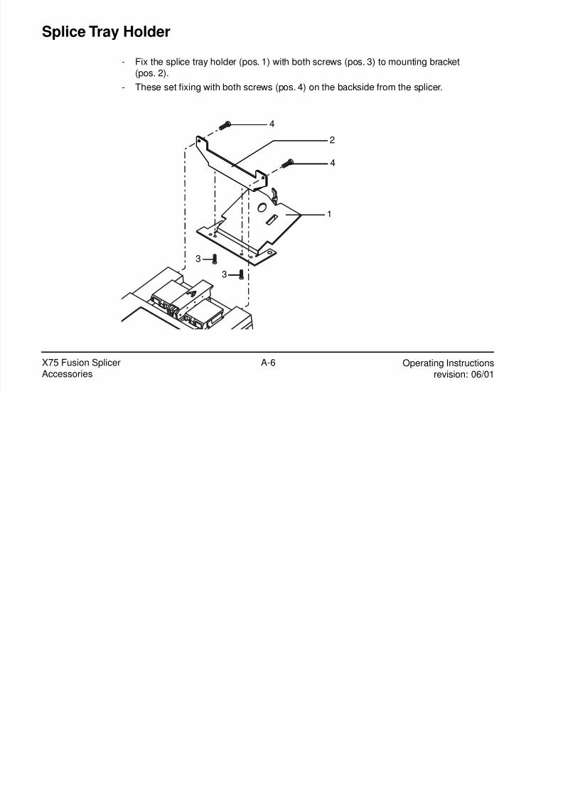
8/10/2019 fusionneuse
http://slidepdf.com/reader/full/fusionneuse 94/94
Operating Instructionsrevision: 06/01
X75 Fusion SplicerAccessories
A-6
These set fixing with both screws (pos. 4) on the backside from the splicer.
1
2
3
4
4
3