further studies of double-punch test for tensile …
TRANSCRIPT

!i
FURTHER STUDIES OF DOUBLE-PUNCH TEST
FOR TENSILE STRENGTH OF CONCRETE
;.byj, T. A. Colgrove
• and~,W. F. Chen
FRITZ ENGINEERINGLABORATORY LIBRARY
Department of Civil Engineering
Fritz Engineering LaboratoryLehigh University
Bethlehem, Pennsylvania
September 1972
. Fritz Engineering Laboratory Report No. 344.1
P8 2.1..'/ 1 "/AS$2.').rN7"I~
I
I\;
\
\
,
..•.
i
FURTHER STUDIES OF DOUBLE-PUNCH TEST
FOR TENSILE STRENGTH OF CONCRETE
by
T. A. Colgrovel and W. F. Chen2
ABSTRACT
The tensile strength of concrete is most commonly measured
using the indirect split-cylinder test. Recently a new test, the
double punch test, has been proposed. The new test method has undergone
preliminary experimental study to determine the testing procedure
which would yield the most reliable and consistent results. However,
further study was needed. Using the previously recommended procedure,
the effect of several additional parameters on the tensile strength
was studied.
These parameters include the rate of stressing during the
'test, and the effect of lightweight as well as regular concrete. Also
being studied is the effects .nf the molds, machine lubricant, and
testing machine. The analysis of these results has led to a more thorough
understanding and greater applicability of the new tensile test.
lSenior Student, Department of Civil Engrg., Lafayette College, Easton, Pa.2Assoc. Prof., Department of Civil Engrg., Fritz Laboratory, Lehigh University, Bethlehem, Pa .

-1
1. INTRODUCTIO~
The tensile strength of concrete can be obtained from
several different tests, such as direct pull tests on briquettes,
flexural tests on beams, and splitting tests on cylinders. The most
cornmon is the indirect split cylinder test (Brazilian test). In countries
where the compressive strength is determined from cubes rather than from
cylinders, the tensile strengths have been obtained using a split cube
or a cube specimen tested diagonally. However, there are drawbacks
connected to each of these tensile tests. Recently, a new alternative
test for concrete, the double-punch test has been developed [lJ.
Preliminary work has been conducted and has resulted in the determination
of a standard procedure for the test [2J. The purpose of the work
represented here was to further investigate experimentally the results
of varying several parameters, including the rate of stressing during
the test, and the effect of lightweight as well as regular concrete.
Also observed was whether the new test accurately reflected changes
in molds, machine lubricant, and testing machine. This study has led
to a more thorough understanding and greater applicability of the test.
The ultimate goal in this study is to prepare this test for acceptance
into the specifications of the American Society of Testing and Materials.
2. TEST PROCEDURE
The double punch test consists of a6 x 6in. (15.30 x 15.30 cm.)
concrete cylinder placed vertically between the loading platens of the
testing machine and compressed by two l~ in.(3.80 cm.) diameter steel
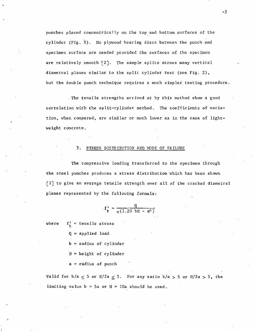
-2
punches placed concentrically on the toP. and bottom surfaces of. the
cylinder (Fig. 1). No plywood bearing discs between the punch and
specimen surface are needed provided the surfaces of the specimen
are relatively smooth [2J. The sample splits across many vertical
diametral planes similar to ~he split cylinder test (see Fig. 2),
but the double punch technique requires a much simpler testing procedure.
·The tensile strengths arrived at by this method show a good
correlation with the split-cylinder method. The coefficients of varia-
tion, when compared, are similar or much lower as in the case of light-
weight concrete.
3. STRESS DISTRIBUTION AND MODE OF FAILURE
The compressive loading transferred to the specimen through
the steel punches produces a stress distribution which has been shown
[lJ to give an average tensile strength over all of the cracked diametral
planes represented by the following formula:
. f' =Q
t TT(1.20 bH - a2 )
where f' tensile stresst
Q = applied load
b = radius of cylinder
H = height of cylinder
a = radius of punch
Valid for b/a ~ 5 or H/2a ~ 5. For any ratio b/a > 5 or H/2a > 5, the
limiting value b = ·5a or H = lOa should be used.

-3
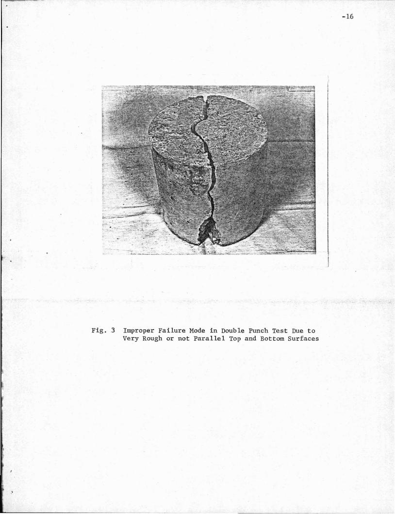
The ideal failure mode for the double punch test is for
the specimen to fail in many radial cracks. Since the strength is
an average value, the greater the number of these radial cracks., the
more accurate the value of the strength. Many cracks also indicates
more even stress distribution in the test specimen. Where'the specimen's
top and bottom surfaces are very rough or not parallel to each other
the specimen may fail in only two cracks, and usually at a significantly
lower load (Fig. 3). Most specimens fail in three or four cracks.
4. EXPERIMENTAL DETAILS
4.1 Materials
Throughout the experiment two types of coarse aggregate
were used: a 3/4 in. (1.9 ern.) maximum size crushed stone for all
regular concrete specimens, and a 3/4 in. (1.9 ern.) maximum size ex
panded shale cornrnerica11y called Nytra1ite for all lightweight concrete
specimens. The same sand, fineness modulus 2.95, and ordinary type I
Portland cement was used in all cases. Darex was used as an air
entraining agent for the lightweight batches.
4.2 Test Apparatus
The loading punches were made from No. 1018 cold rolled steel
and were 1~ in. (3.80 ern.) in diameter and 1 inch (2.55 ern.) 'thick.
All surfaces were machined, and the ends parallel. Two plywood discs,
6 in. (15.30 ern.) in diameter with a 1.5 in. (3.80 ern.) diameter hole
in the center, were used as templates to center the punches on the
concrete specimen and then between the loading platens of the machine.
-4
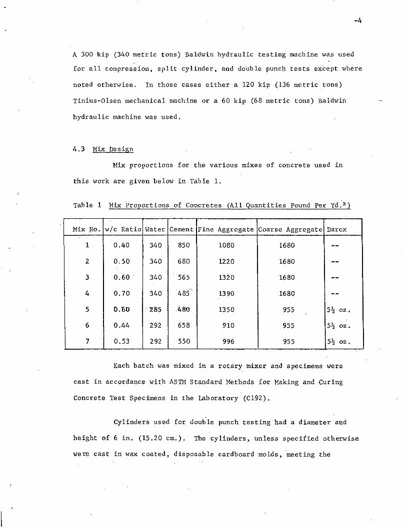
A 300 kip (340 metric tons) Baldwin hydraulic testing machine was used
for all compression, split cylinder, and double punch tests except where
noted otherwise. In those cases either a 120 kip (136 metric tons)
Tinius-Olsen mechanical machine or a 60 kip (68 metric tons) Baldwin
hydraulic machine was used.
4.3 Mix Design
Mix proportions for the various mixes of concrete used in
this work are given below in Table 1.
Table 1 Mix Proportions of Concretes (All Quantities Pound Per Yd. 3 )
Mix No. w/c Ratio Water Cement Fine Aggregate Coarse Aggregate Darex
1 0.40 340 850 1080 1680 --
2 0.50 340 680 1220 1680 --
3 0.60 340 565 1320 1680 --
4 0.70 340 ··485~ 1390 1680 --
5 ·0.00 .. '285 480 1350 955 5~ oz.
6 0.44 292 658 910 955 5~ oz.
7 0.53 292 550 996 955 5~ oz.
Each batch was mixed in a rotary mixer and specimens were
cast in accordance with ASTM Standard Methods for Making and Curing
Concrete Test Specimens in the Laboratory (C192).
Cylinders used for double punch testing had a diameter and
height of 6 in. (15.20 cm.). The cylinders, unless specified otherwise
were cast in wax coated, disposable cardboard molds, meeting the

-5
requirements of ASTM Specifications for Single-Use Molds for Forming
6 by 12 in. Concrete Compression Test Cylinders (C470). These molds
were cut to 6 in. (15.30 cm.) in height for double punch specimens.
Cube specimens were 6 in. (15.30 cm.) on edge and cast in either plywood
or steel molds.
Immediately after casting, the samples were covered with
plastic sheets for a perio9 of 24 hours. The molds were then stripped
from the samples, and the samples were placed in a moist curing room,
ASTM Specifications for Moist Cabinets and Rooms Used in the Testing
of Hydraulic Cements and Concretes (C5ll), for the remaining 27 days.
Lightweight specimens were removed from the moist curing room after
7 days and covered with wet burlap and plastic for the remaining 21
days.
Standard control specimens were cast for each mixture.
5. RESULTS
5.1 Control Tests
Control tests were made for each mix and the values are shown
in Table 2 below.
-6
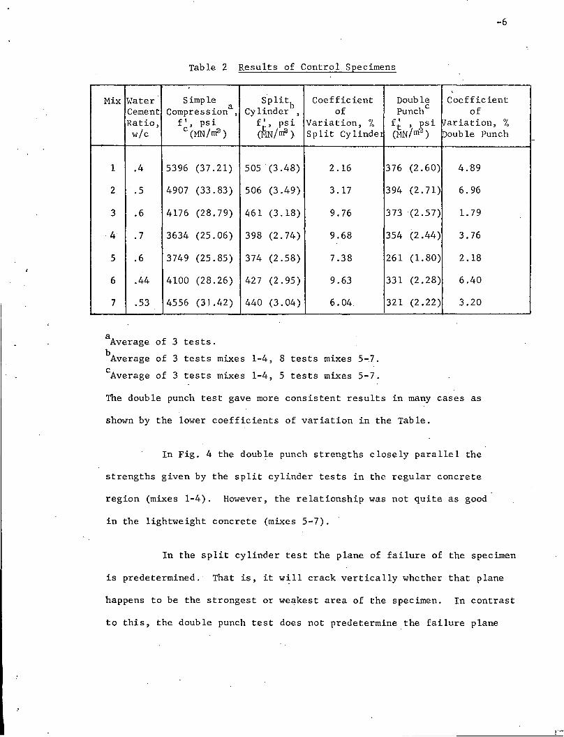
Table 2 Results of Control Specimens
, ,
Mix Water Simple S'plitb Coefficient Double Coefficient
. a of Punchc ofCement Compress~on , Cylinder ,Ratio, f I, ps i f ~, ps i Variation, % f~ , psi Variation, %w/c c (MN/m2) (HN/rrfl ) Split Cy linde! C'r1N/ rrY3 ) Double Punch
1 .4 5396 (37.21) 505 (3.48) 2.16 376 (2.60) 4.89
2 .5 4907 (33.83) 506 (3.49) 3.17 394 (2.71) 6.96
3 .6 4176 (28.79) 461 (3.18) 9.76 373 (2.57 ) 1. 79
4 .7 3634 (25.06) 398 (2.74 ) 9.68 354 (2.44) 3.76
5 .6 3749 (25.85) 374 (2.58) 7.38 261 (1.80) 2.18
6 .44 4100 (28.26) 427 (2.95 ) 9.63 331 (2.28) 6.40
7 .53 4556 (31.42) 440 (3.04) 6.04 321 (2.22 ) 3.20
aof 3Average tests.
bof 3 mixes 1-4, 8 mixes 5-.7.Average tests tests
c of 3 mixes 1-4, 5 mixes 5-7.Average tests tests
The double punch test gave more consistent results in many cases as
shown by the lower coefficients of variation in the Table.
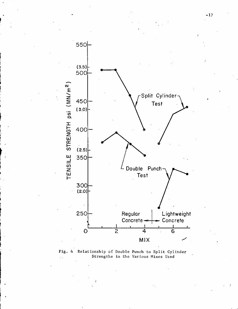
In Fig. 4 the double punch strengths closely parallel the
strengths given by the split cylinder tests in the regular concrete
region (mixes 1-4). However, the relationship was not quite as good
in the lightweight concrete (mixes 5-7).
In the split cylinder test the plane of failure of the specimen
is predetermined. That is, it w~ll crack vertically whether that plane
happens to be the strongest or weakest area of the specimen. In contrast
to this, the double punch test does not predetermine the failure plane

-7
and so will fail in the weakest planes. 'This explains the consistently
lower strengths obtained.
5.2 Effect of Molds
The purposes of this experiment were to investigate any
effects on the double punch test strengths due to different types of
molds and to see whether these effects, if any, are comparable to
those reflected in the split cylinder testing procedure.
In split cylinder testing cylinders cast in cardboard molds
give specimens with lower strengths and higher variability than specimens
cast in steel molds [3J.
Regular and lightweight concrete specimens were cast in both
cardboard and steel cylinder molds. Standard 12 in. (30.50 cm.) card
board molds were cut to 6 in. (15.20 cm.) heights and false bottoms
were made for the steel molds. Cube specimens were also cast in both
plywood and steel molds.
The results in Table 3 show the double punch test consistently
reflects greater ~trengths and lower coefficients of variation in the
case of steel molds. This therefore indicates the sensitivity of the
double punch method to record these changes.

-8
Table 3 Effect of Mold Type on Specimen Strength
Cylinder Cube
Cardboard Steel Plywood Steel
Mix 4a psi (MN/m2 ) 333 (2.30) 364 (2.51) 335. (2.31) 354 (2.44)Strength
Regular Coefficient of Variation 5.98 2.07 1.53 1.32
Mix 5 Strengtha psi (MN/m2) 261 (1.80) 264 (1. 82) 271 (1. 87) 274 (1. 89)
Light- Coefficient of Variation 2.18 2.64 2.99 1. 78weight
aAverage of 4 tests
5.3 Effect of Stressing Rate
The influence of the stressing rate was measured by testing
mixes 3 and 5 each at 7 and 28 days. Regular concrete (mix 3) showed
a gradual decrease in the strength with an increased rate (Fig. 5).
Lightweight concrete (mix 5) was found to be more sensitive to the rate.
Beyond 200 psi/min. the strength rose steeply to around 500 psi/min. then
fell off. The 28 day strengths are also given in Table 4.
Table 4 Effect of Stressing Rate
Mix 3 Mix 5a· Coefficient of a Coefficient ofRate Strength Strength
psi/min. (MN/m2 /min) psi (HN/m2) Variation, % psi (MN/m2) Variation, %..
100 (0.69) 379 (2.62) 2.74 264 (1. 82) 1.59
200 (1.38) 390 (2.69) 4.14 261 (1.80) 2.18
300 (2.07) 364 (2.51) 7.23 276 (1. 90) 6.46
500 (3.45) 368 (2.54) 4.18 287 (1. 98) 4.75
1000 (6.89) 362 (2.50) 14.00 267 (1. 84) 3.72
aAverage of 6 test results at 28 days.
-9
5.4 Effect of Testing Machine
Testing machine conditions may significantly affect ,the
measured strength of concrete. Care must be taken to accurately align
the punches and specimen in the testing machine. Each of the testing
machines used was fitted with a spherical bearing block on the upper
platen. Tests were made on the type of lubricant used on the upper
platen. With a poor lubricant, the platen is able to move initially
but then breaks down under load and becomes effectively fixed. With
a high pressure lubricant the spherical bearing block is 'able to
adjust throughout the loading.
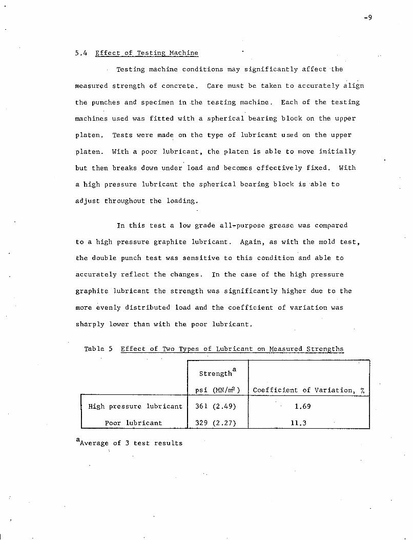
In this test a low grade all~purpose grease was compared
to a high pressure graphite lubricant. Again, as with the mold test,
the double punch test was sensitive to this condition and able to
accurately reflect the changes. In the case of the high pressure
graphite lubricant the strength was significantly higher due to the
more evenly distributed load and the coefficient of variation was
sharply lower than with the poor lubricant.
Table 5 Effect of Two Types of Lubricant on Measured Strengths
aStrength
psi (MN /ni3 ) Coefficient of Variation, %
High pressure lubricant 361 (2.49) 1.69
Poor lubricant 329 (2.27) 11.3
aAverage of 3 test results
-10
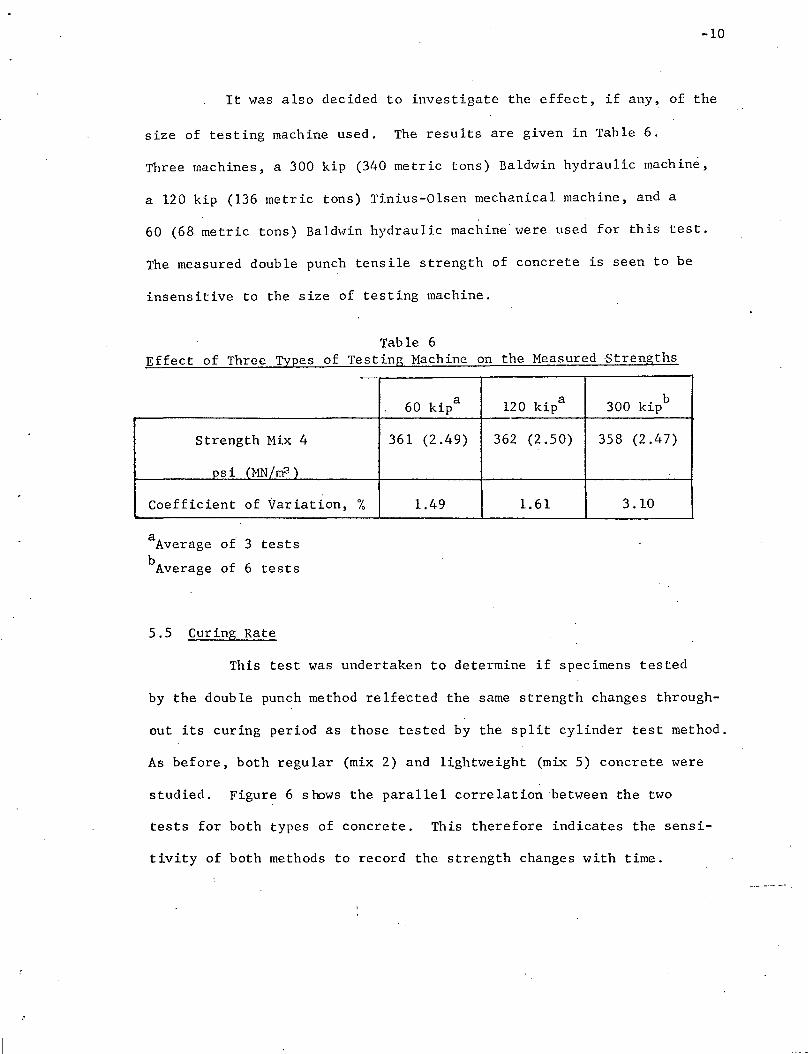
It was also decided to investigate the effect, if any, of the
size of testing machine used. The results are given in Table 6.
Three machines, a 300 kip (340 metric tons) Baldwin hydraulic machine,
a 120 kip (136 metric tons) Tinius-01sen mechanical machine, and a
60 (68 metric tons) Baldwin hydraulic machine were used for this test.
The measured double punch tensile strength of concrete is seen to be
insensitive to the size of testing machine.
Table 6Effect of Three Types of Test ing Machine on the Measured -Strengths
60 kipa 120 kipa 300 k' b~p
Strength Mix 4 361 (2.49) 362 (2.50) 358 (2.47)
Dsi (MN /rrf.3 )
coefficient of Variation, % 1.49 1.61 3.10
aAverage of 3 testsbAverage of 6 tests
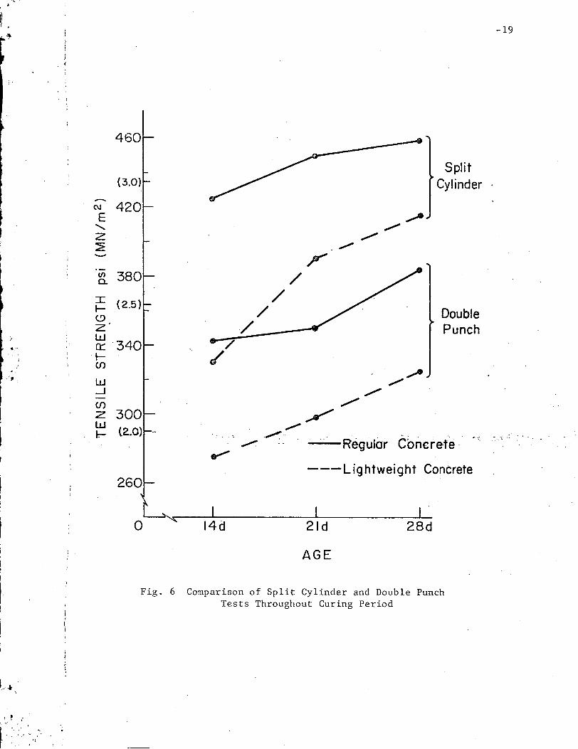
5.5 Curing Rate
This test was undertaken to determine if specimens tested
by the double punch method re1fected the same strength changes through-
out its curing period as those tested by the split cylinder test method.
As before, both regular (mix 2) and lightweight (mix 5) concrete were
studied. Figure 6 shows the parallel correlation -between the two
tests for both types of concrete. This therefore indicates the sensi-
tivity of both methods to record the strength changes with time.

6. ADVANTAGES OF THE DOUBLE PUNCH TEST
There are four primary advantages of the double punch test
over the split cylinder test. These are:
1. It gives an average tensile strength which exists over
all of the failure planes, and a "truer" strength than the
split cylinder test because of the weak link theory.
2. It is much simpler to perform than the split cylinder test
method.
3. Because the ultimate load needed for failure is much lower
(20-30 kips compared to 40-60 kips), a smaller machine can
. be used; This makes the test more attractive for field
tests with portable machines.
4. For those countries which use cubes for compression tests,
the double punch method is much easier than the diagonal
split cube procedure.
7 • CONCLUS IONS
1. Control Tests
The strengths of concrete obtained by the double punch
test are generally more consistent than those obtained by the split
cylinder test method.
2. Molds
The double punch procedure showed that the use of steel
molds for casting specimens gave higher strengths with lower varia
bility than those in cardboard molds, and is therefore sensitive to
the type of mo Id used.
-11

-12
3. Stressing Rate
Increasing the stressing rate for the double punch test gives
lower strengths for regular concrete specimens and higher strengths
in the case of lightweight concrete samples.
4. Testing Machine
The double punch tesni1e strength of concrete test specimens
is independent of the size testing machine used. However the type of
lubricant used on the upper platen does 'affect the measured strength.
A good (high pressure) lubricant results in higher and less variable
tensile strengths.
5. Curing Rate
The double punch test and the split cylinder test reflect
comparable increases in tensile strength throughout the curing period
of test specimens.
8. RECOMMENDATIONS
In order to standardize test procedure and therefore make
results reproducible from laboratory to laboratory it is recommended,
based on the past [2J and present studies, that:
1. To'use 6 in. by 6 in. concrete cylinders;
2. To use 1~ in. diameter steel punches;
3. No plywood bearing discs are needed;
4. To use a stressing rate of 100-200 psi per minute;
5. To use high pressure lubricant on the spherical bearing
block for lower testing variability during the double punch test.

-13
9. ACKNOHLEDGHENTS
The research reported herein was supported by the National
Science Foundation under Grants GY-9989 and GK-14274 to Lehigh Univer-
sity.
10. REFERENCES
1. Chen, W. F. "Double Punch Test for Tensile Strength of Concrete",Journal of the American Concrete Institute, Vol. 67, December1970, pp. 993-995.
2. Chen, W. F. and Trumbauer, B. E. "Double Punch Test and TensileStrength of Concrete", Journal of Haterials, American Societyfor Testing and Materials, Vol. 7, No.2, June 1972, pp. 148154.
3. Cornelius, D. F., Franklin, R. E., King, T. M. J. "The Effect ofTest Method on the Indirect Tensile Strength of Concrete",PRL Report LR 260, Road Research Laboratory, Ministry ofTransport, Crowthorne, Berkshire, 1969.
r --~

-14
Fig. 1 Test Set-Up for the Double Punch Test

(a)
(b)
;... - .. -::...o.:r_-==_,
-15
.'
Fig. 2 Example of Double Punch Failure Mode
-16
Fig. 3 Improper Failure Mode in Double Punch Test Due toVery Rough or not Parallel Top and Bottom Surfaces
-17
550
(3.5)
500
-NE"- Split Cyl inderz~ 450 Test......
, ( 3.0)
~ena.
~J:.- 400(!),- z
~ wI 0:::.-
r:(f) ( 2.5)
W 350-J(f)
Double Punch, zw Test.-
300I (2.0)~
•!t Regular -+- LightweightI
Concrete . Conc reteI,
f
0 2 4
MIX ./
" Fig. 4 Relationship of Double Punch to Split CylinderStrengths in the Various Mixes Used

380(2.6)
-18
a 100 200 300 500
RATE psi/min.
1000
Fig. 5 Results of 28 Day Tensile Strength vs. Rate of Loading
....'O":~-. -
,)
, ~
• I
o 21d 28d
-19
,'./" .. ,
. .. ..' . . .', ~ ''''. .'• '. • OJ
AGE
Fig. 6 Comparison of Split Cylinder and Double PunchTests Throughout Curing Period